avr341: four and five-wire touch screen controller · avr341: four and five-wire touch screen...
TRANSCRIPT
8-bit Microcontrollers Application Note
Rev. 8091A-AVR-07/07
AVR341: Four and five-wire Touch Screen Controller
Features • Reading touch screen coordinates for 4- and 5-wire screens • Measurement of screen resistance (4-wire) • Translation of touch coordinates into screen coordinates.
1 Introduction Resistive 4- and 5-wire touch systems belong to the most popular and most common touch screen technologies. Their market share is about 75%, mainly due to their low costs and simple interface electronics. Resistive System can be found in various mobile applications including PDAs and Smartphones.
AVR® microcontrollers are excellent in this type of application due their analog features combined with low power modes, required in e.g. portable battery powered applications.

2 AVR341
2 Theory of operation - analog resistive touch screens Usually a resistive touch screen consists of at least three layers: A flexible membrane made from PET film is suspended over a rigid substrate made from glass or acryl (see Figure 2-1). Both surfaces are coated with a transparent conductive film like ITO (Indium tin oxide). The conductive ITO layers are kept apart by an insulting spacer along the edges, and by spacer dots on the inner surface of the two ITO layers. In this way there will be no electrical connection unless pressure is applied to the topsheet (PET film).
Figure 2-1. Resistive touch screens.
4-wire touch screens use a single pair of electrodes (“Busbars”) on each ITO layer (see Figure 2-2). The busbars in the topsheet and substrate are perpendicular to each other. The busbars are connected to the touch screen controller through a 4-wire flex cable. The 4 wires are referred as X+ (left), X- (right), Y+ (top) and Y- (bottom).
An advantage of the 4-wire touch screens is that it is possible to determine the touch pressure by measuring the contact resistance (RTouch) between the two ITO layers. RTouch decreases as the touch pressure (or the size of the depressed area) increases. This characteristic can be useful in applications in which it is not only required to detect where the pressure is applied, but also the type of pressure (area and force).
8091A-AVR-07/07

AVR341
Figure 2-2. Electrodes in 4- (right figure) and 5- wire (left figure) touch screens.
5-wire touch screens have circular electrodes (see Figure 2-2). Since all of them reside in the substrate ITO there is a need for linearization pattern (conductive) to make an applied voltage gradient uniform.
4 wires connect to the electrodes these are referred to as UL (Upper Left), UR (Upper Right), LL (Lower Left), LR (Lower Right). The fifth wire is used for sensing the electrode voltage and is referred to as the “sense” wire. The sense wire is embedded in the topsheet. The advantage of the 5-wire touch screen type is that the ITO coating on the topsheet is not required to be perfect. This means that physical wearing of the 5-wire touch screens is less critical than for 4-wire touch screens.
2.1 Excitation and measurement method The method for measuring the pressure point is based upon a preferably homogenous resistive surface (ITO). When applying a voltage to the electrode pair in the resistive surface a uniform voltage gradient appears across the surface. A second ITO layer is necessary to do a high-resistance voltage measurement. A resistive touch screen can thus be seen as an electrical switch requiring a small amount of pressure (0.1 – 1.5 Newton) to close.
3
8091A-AVR-07/07

4 AVR341
Figure 2-3. “Schematic” of a 4-wire touch screen when pressure is applied.
The point of contact “divides” each layer in a series resistor network with two resistors (see Figure 2-3), and a connecting resistor between the two layers. By measuring the voltage at this point the user gets information about the position of the contact point orthogonal to the voltage gradient. To get a complete set of coordinates, the voltage gradient must be applied once in vertical and then in horizontal direction: first a supply voltage must be applied to one layer and a measurement of the voltage across the other layer is performed, next the supply is instead connected to the other layer and the opposite layer voltage is measured. In stand-by mode one of the lines are connected to a level triggered interrupt in order to detect touch activity. Please refer to Table 2-1 for connections while measuring the coordinates.
Table 2-1. 4-wire touch screens scanning X+Excite X-Excite Y+Excite Y-Excite
Standby Gnd Hi-Z Hi-Z Pull up / Int
X-Coordinate Gnd Vcc Hi-Z Hi-Z / ADC
Y-Coordinate Hi-Z Hi-Z / ADC Gnd Vcc
A 5-wire touch screen only use the topsheet for measuring. Please refer to Table 2-2 for connections while measuring the coordinates on 5-wire touch screens.
Table 2-2. 5-wire touch screens scanning. ULExcite URExcite LLExcite LRExcite Sense
Standby Gnd Hi-Z Hi-Z Hi-Z Pull up / Int
X-Coordinate Gnd Vcc Gnd Vcc Hi-Z / ADC
Y-Coordinate Gnd Gnd Vcc Vcc Hi-Z / ADC
To get a complete set of coordinates, the voltage gradient is applied on the substrate layer once in horizontal direction to determine the Y coordinate and once in vertical direction to determine the X coordinate. In both cases the topsheet layer is used to do a high-impedance measurement after the sensing voltage has settled. In standby
8091A-AVR-07/07

AVR341
mode the fifth wire (sense) is connected to a level triggered interrupt in order to detect touch activity.
2.2 Calculation of the 4-wire touch pressure As mentioned it is possible to determine the force that is applied on a 4-wire touch screen. Table 2-1 describes the scan pattern used to do so. Equation 2-1 and Equation 2-2 shows how to calculate the resistance.
Table 2-3. 4-wire touch screens scanning X+Excite X-Excite Y+Excite Y-Excite
Z1 Gnd Hi-Z / ADC Hi-Z Vcc
Z2 Gnd Hi-Z Hi-Z / ADC Vcc
By means of Ohms Law there are two different methods to determine RTouch (see Figure 2-3
Equation 2-1. Calculation of RTouch.
⎟⎟⎠
⎞⎜⎜⎝
⎛−⋅=
−=
12
)(
1
2__
12
Z
ZresolutionADC
XPlateX
ZZTouch
ADCADCADCR
IUU
R
The first method requires a known X-plate resistance and two additional cross-panel measurements (Z1 and Z2) of the touch screen. The second method requires that the X- and Y-plate resistance values are known but allows the use of a single measurement only (Z1).
Equation 2-2. Calculation of RTouch.
⎟⎠⎞
⎜⎝⎛ −−⎟⎟
⎠
⎞⎜⎜⎝
⎛−=
−−=
−−=
+−
+−
resolutionADCY
PlateYZ
resolutionADC
resolutionADCPlateX
X
YXREF
YXgesTouch
ADCRADC
RADC
RRI
U
RRRR
__1
_
__
2112
2
2.3 Touch bouncing Resistive touch screens, especially the inexpensive ones, are notoriously bouncy and susceptible to glitches, and therefore filtering of the determined coordinates is necessary. Though external components can be used to implement analog filtering, this will add cost to the design. A better way to achieve correct coordinates (“points”) is to run a digital filter in software: a median filter is a good choice, as it eliminates incorrect measurements. A digital filter, however, implies several measurements to get a single X or Y coordinate pair. It is also possible to introduce corrective actions by defining conditions that needs to be fulfilled to accept a new set of coordinates:
5
8091A-AVR-07/07
6 AVR341
• Switch back to standby mode and confirm contact before and after new measurements are taken
• Take the value of RTouch into account. • Accept new values only if they fit in a well-defined noise window
The end of a touch can also be detected. The error rate of the system will decrease by increasing complexity of filtering. There is an unavoidable trade-off between accurate measurements and high conversion rates. Accurate measurements require more data samples, but lower the conversion rate which may cause perceivable delays. Hence the touch system should be designed so that coordinates are generated within 50 to 100 ms.
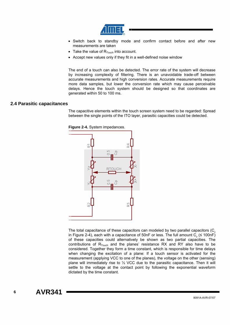
2.4 Parasitic capacitances The capacitive elements within the touch screen system need to be regarded: Spread between the single points of the ITO layer, parasitic capacities could be detected.
Figure 2-4. System impedances.
The total capacitance of these capacitors can modeled by two parallel capacitors (Cp in Figure 2-4), each with a capacitance of 50nF or less. The full amount Cp (≤ 100nF) of these capacities could alternatively be shown as two partial capacities. The contributions of RTouch and the planes’ resistance RX and RY also have to be considered. Together they form a time constant, which is responsible for time delays when changing the excitation of a plane: If a touch sensor is activated for the measurement (applying VCC to one of the planes), the voltage on the other (sensing) plane will immediately rise to ½ VCC due to the parasitic capacitance. Then it will settle to the voltage at the contact point by following the exponential waveform dictated by the time constant.
8091A-AVR-07/07
AVR341
7
8091A-AVR-07/07
)
Equation 2-3. Time constant.
( ) ( XPlateYPlateXTouchXHSP RRbRaRCCCRC
+⋅+⋅+⋅++==
−−/
τ
Note: Coefficients „a“ and „b“ depend on touch position; CX and RX represent additional parasitic elements like wire resistance, internal logic impedance of the controller etc.
3 Requirements for a touch screen controller To operate a 4- or 5-wire touch screen, there are several requirements regarding the controller.
3.1 ADC An A/D converter with a resolution of 10 bits and the absolute inaccuracy far under the linearity error of the touch screen (1,5%-3%) is required for the conversion of the analog values into digital values.
When considering the minimum detection time for applied pressure on the screen and changes in coordinates, the conversion time of the ADC must be considered. In an application only monitoring clicks, 70 points per seconds is typically needed. For detection of motion, e.g. handwriting, one should calculate approximately 200 points per second - taking into account that multiple measurements are included to compass the correct point (by oversampling and digital filtering). Also, the CPU must be able to process the ADC readings with sufficient computational accuracy to not reduce the detection rate.
3.2 I/O pins The pins driving the touch screen must be able to sink and source in the range of 5-25mA (depending on the value of the ITO resistance and the voltage used). This means that 4 digital IO pins and two analog inputs (ADC channels) are required. If the pins can be configured as both analog input and digital IO, 4 pins are sufficient for a 4-wire touch screen controller.
A 5-wire touch screen controller just needs one analog input line – to measure the sense line.
3.3 Timer A timer is used as a scheduler for different purposes. Since the proposed method is interrupt driven, there is no need for additional delays, e.g. in order to debounce the touch screen. The timer can also be used to trigger the ADC and set the I/O pins in the correct order immediately before a measurement starts. In this way, the controller powers the touch screen only for a minimum of time. Furthermore, a timer can be used to create a timeout function, which sets the controller into sleep mode when no activity is detected on the touch screen for a certain amount of time.
3.4 Activity detection As touch screens are often used in portable applications, the power consumption of the touch screen controller should be taken into account. One way to reduce the

8 AVR341
power consumption is to let the touch screen controller enter low power sleep modes (“standby”) when no activity is detected on the touch screen.
To enable the use of standby operation, a level-change detection should be implemented using a pin change interrupt combined with an internal pull-up. This allows the touch screen controller to enter low power mode while waiting for activity on the touch screen, and wake up when the pin change is triggered.
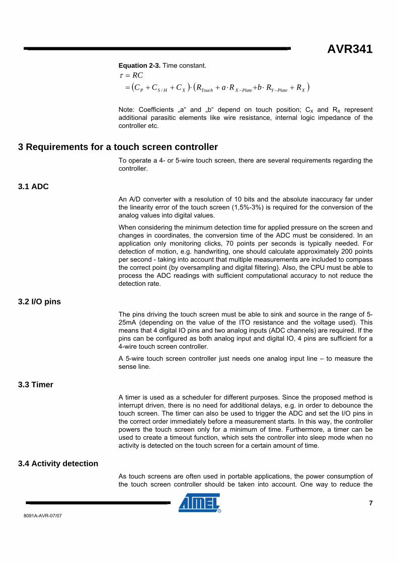
3.5 Connecting the touch screen to the AVR The implementation example uses the ATmega88 as touch screen controller (see datasheet ATmega88 for details). Figure 3-1 and Figure 3-2 illustrates how to connect the ATmega88 to respectively a 5-wire and a 4-wire touch screen. In order to drive a 5-wire touch screen one have to connect the sense line to an ADC channel input of the AVR. A 4-wire touch screen needs two ADC input channels (X- and Y-). The remaining lines should be connected to any I/Os, but preferably on the same port. As voltage reference it is recommended to use AVCC with an external capacitor on the AREF pin. To minimize noise signals (e.g. from a LCD display) it is common to add capacitors from the touch screen drivers to ground forming a low-pass filter (typical value 0.01µF), but you have to consider that this step will increase the time constant of your system.
Figure 3-1. Design suggestion for 5-wire touch screens.
8091A-AVR-07/07
AVR341
Figure 3-2. 4-wire touch screen with UART connection.
4 Code example The code is implemented with the EWAVR IAR® compiler version 4.20A. The code targets the ATmega88, but can run on other devices with only minor modifications to the code.
The implementation includes the following:
Driver for interfacing a resistive 4- or 5-wire touch screen (selected through defines)
• Debouncing. • Correction for parasitic capacitances • Filtering or read coordinates (median filter) • Optional determination of RTouch for filter purposes (4-wire only) • Standby mode
The implementation is intended to be used as a low level driver, so no interpretation of data (distinguish between clicks and dragging) or calibration is performed. The driver will only provide valid coordinates and status information (written to a “Flag Register”).
The touch screen driver can be completely configured by several defines in “touchscreen.h”. It is possible to choose between a 4- and a 5-wire touch screen, and it is an option to measure RTouch on a 4-wire system for filtering purposes. Furthermore, it is possible to select which pins are connected to the touch screen. The project was originally written for ATmega88, but it can be adapted to almost most AVRs since all used bit and register definitions are listed in this file.
To use the touch screen driver in an application, add the files (touchscreen.h, touchscreen.c) and include the header file. The function “Touchscreen_Init” will initialize the driver. An external structure variable named “Touchscreen_Data”, which consists of an 8-bit Flag Register and two 16-bit variables for the actual X/Y
9
8091A-AVR-07/07

10 AVR341
coordinates, offers all necessary information to handle the touch system. See Figure 4-1 for a description of the Flag Register.
Figure 4-1. “Touchscreen_Data” - Flag Register.
Figure 4-2. “Touchscreen_Data” - X/Y coordinates.
Table 4-1. Definition of the bits in the “Flag Register” Flag Function
Start (set in: Touchscreen_init)
This bit indicates the end of the initialization routine, which must be run the first time the application is run. It is recommended to run a calibration of mapping between touch coordinates and display screen coordinates in relation to starting up the application the first time. (Please refer to section 5.1 regarding calibration).
Sleep (Timer0 OCMA)
This bit is set if there are no new inputs on the touch sensor for a predefined time (SLEEP_COUNTDOWN in “touchscreen.h”). In order to save power you can enter sleep mode of the AVR when this bit is set. (See comments in “main.c”).
Touch (Timer0 OCMA)
This bit indicates that a touch was detected and the debouncing process was successfully finished. The touch screen driver will now start the ADC and perform a number of measurements.
End (ADC ISR)
This bit is set if the end of a touch was detected. The touch screen driver will now disable the ADC and set the “Sleep Flag” after a predefined time if no new inputs are recognized.
8091A-AVR-07/07

AVR341
11
8091A-AVR-07/07
Flag Function
X/Y (ADC ISR)
This bit indicates that a set of new coordinates was written into the Touchscreen_Data struct.
Overflow (ADC ISR)
This bit indicates that a new set of coordinates was written into the Touchscreen_Data struct before an older one has been read.
4.1 RS232 interface for status information Status information is transmitted on the ATmega88 UART, to enable the user to see the state and output from the coordinate detection (see Figure 4-3). This includes information about wake-up from sleep (“Touch) and entering stand-by mode (“sleep”). All information can be viewed with a terminal program (Settings: 19200 Baud, 8n1) using ASCII characters.
Figure 4-3. RS-232 terminal interface.

12 AVR341
4.2 Overview of main code loop In order to respond to the different flags they must be polled accordingly. In the UART-demonstration code example a special function („Recognize_Event“) will do the interpretation of the flags (see Figure 4-4). Since almost all flags are set in interrupt routines, the function first disables global interrupts and then copies the structure into a buffer to ensure data integrity. Additionally, it is possible to apply a mask on the Flag Register so only the important tasks will be responded to (e.g. only respond to new coordinates). After the flags have been processed, the corresponding flags are cleared. Finally, the global interrupts are enabled again.
In the code example all flags and coordinates will be transmitted as ASCII characters using the UART-interface, so it is possible to monitor the status and detected coordinates using a terminal program.
Figure 4-4. Flowchart of „main“-function.
Main()
Call„Send_over_UART“
Recognize Event?
Initialize UART-Interface
Initialize Touchscreen
Enable global Interrupts
yes
no
Recognize_Event
Enable global Interrupts
Disable global Interrupts
Save variable„Touchscreen_Data“ in
buffer
Mask flag register (buffer) =imported flags
Delete imported flags fromvariable
„Touchscreen_Data“
Return flag register ofbuffer
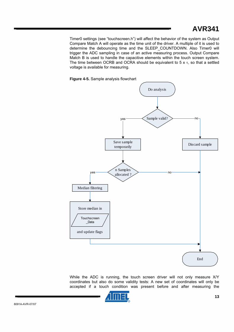
4.3 Description of the touch screen control driver Figure 4-5. Sample analysis flowchart and Figure 4-6. Touch screen driver workflow give an overview of the touch screen control driver.
8091A-AVR-07/07
AVR341
Timer0 settings (see “touchscreen.h”) will affect the behavior of the system as Output Compare Match A will operate as the time unit of the driver. A multiple of it is used to determine the debouncing time and the SLEEP_COUNTDOWN. Also Timer0 will trigger the ADC sampling in case of an active measuring process. Output Compare Match B is used to handle the capacitive elements within the touch screen system. The time between OCRB and OCRA should be equivalent to 5 x τ, so that a settled voltage is available for measuring.
Figure 4-5. Sample analysis flowchart
Median filtering
n Samplesallocated ? noyes
Do analysis
End
Sample valid?
Discard sample
no
Save sampletemporarily
yes
Store median in
and update flags
Touchscreen_Data
While the ADC is running, the touch screen driver will not only measure X/Y coordinates but also do some validity tests: A new set of coordinates will only be accepted if a touch condition was present before and after measuring the
13
8091A-AVR-07/07
14 AVR341
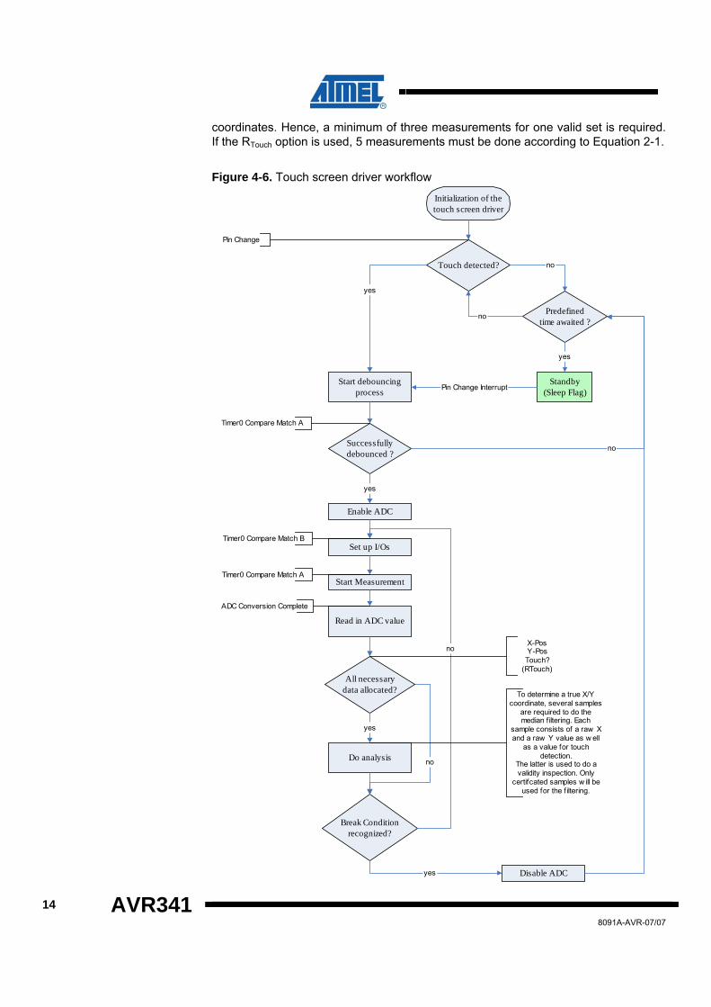
coordinates. Hence, a minimum of three measurements for one valid set is required. If the RTouch option is used, 5 measurements must be done according to Equation 2-1.
Figure 4-6. Touch screen driver workflow
Pin Change
Initialization of thetouch screen driver
Start debouncingprocess
Touch detected?
Successfullydebounced ?
Enable ADC
Set up I/Os
Start Measurement
Read in ADC value
yes
yes
Break Conditionrecognized?
Standby(Sleep Flag)
no
Pin Change Interrupt
no
yes Disable ADC
Predefinedtime awaited ?
no
All necessarydata allocated?
yes
no
Do analysis
yes
no
Timer0 Compare Match B
Timer0 Compare Match A
ADC Conversion Complete
Timer0 Compare Match A
To determine a true X/Ycoordinate, several samples
are required to do themedian f iltering. Each
sample consists of a raw Xand a raw Y value as w ell
as a value for touchdetection.
The latter is used to do avalidity inspection. Only
certifcated samples w ill beused for the f iltering.
X-PosY-PosTouch?
(RTouch)
8091A-AVR-07/07

AVR341
15
8091A-AVR-07/07
Accepted values are stored in a corresponding array, until a predefined number of values are achieved („SAMPLES_FOR_ONE_TRUE_XY_PAIR“). If this is the case, both X and Y arrays will be sorted and the median is identified (median filter). The median is a number dividing the higher half of the sample data from the lower half, so in case of an array with sorted values it is the middle one. This filter was chosen because of its ability to eliminate glitches while allowing fast dragging.
The median for the ongoing X and Y coordinate will be provided to the user in the interface variable “Touchscreen_Data”.
The consecutively measurements of coordinates and touch conditions will be aborted if a successive number of touch conditions („MAXIMUM UNTOUCH CONDITIONS“) proves that there is no longer a contact between the two ITO layers.
4.4 Interrupts used by touch screen driver The touch screen driver uses a total of 4 different interrupt sources. For this reason no delay times are necessary and the response time of the system is reduced to a minimum.
The following interrupts are used:
Pin Change Interrupt: The Pin Change Interrupt is used to detect a touch and wake up the AVR from sleep mode. This interrupt will start Timer0.
Timer0, Compare Match A: This interrupt is first used to debounce the touch screen. If this process succeeded, the interrupt will start a new ADC measurement each time it occurs. If no touch activity is detected the timer will increment the SLEEP_COUNTDOWN and finally set the Sleep Flag.
Timer0, Compare Match B: Chronologically before OCMA, this interrupt is only active while the ADC is enabled and measurements are done. It configures the I/O pins and sets the analog input channel.
ADC Conversion Complete: In this interrupt the ADC values are read and the filtering is done.
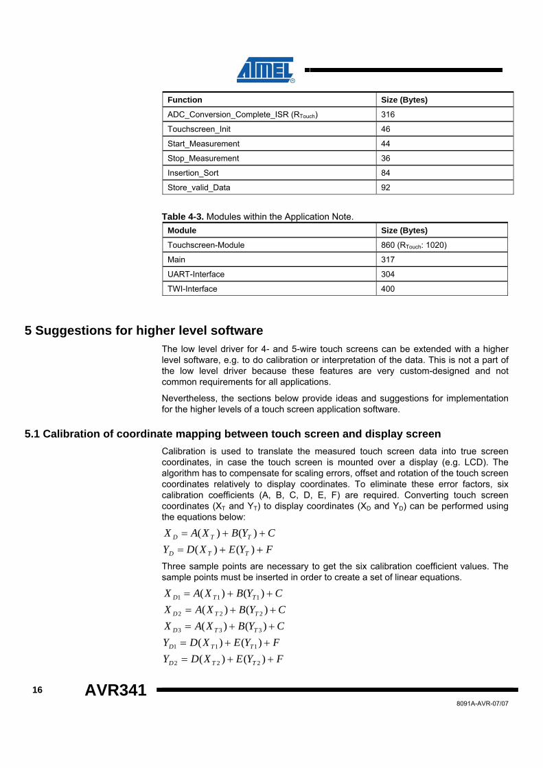
4.5 Code size Table 4-2. Functions of “touchscreen.c“.
Function Size (Bytes)
Pin_Change_ISR 40
Timer0_Compare_Match_A_ISR 135
Timer0_Compare_Match_B_ISR 64
ADC_Conversion_Complete_ISR (Low Level) 176
16 AVR341 8091A-AVR-07/07
Function Size (Bytes)
ADC_Conversion_Complete_ISR (RTouch) 316
Touchscreen_Init 46
Start_Measurement 44
Stop_Measurement 36
Insertion_Sort 84
Store_valid_Data 92
Table 4-3. Modules within the Application Note. Module Size (Bytes)
Touchscreen-Module 860 (RTouch: 1020)
Main 317
UART-Interface 304
TWI-Interface 400
5 Suggestions for higher level software The low level driver for 4- and 5-wire touch screens can be extended with a higher level software, e.g. to do calibration or interpretation of the data. This is not a part of the low level driver because these features are very custom-designed and not common requirements for all applications.
Nevertheless, the sections below provide ideas and suggestions for implementation for the higher levels of a touch screen application software.
5.1 Calibration of coordinate mapping between touch screen and display screen Calibration is used to translate the measured touch screen data into true screen coordinates, in case the touch screen is mounted over a display (e.g. LCD). The algorithm has to compensate for scaling errors, offset and rotation of the touch screen coordinates relatively to display coordinates. To eliminate these error factors, six calibration coefficients (A, B, C, D, E, F) are required. Converting touch screen coordinates (XT and YT) to display coordinates (XD and YD) can be performed using the equations below:
CYBXAX TTD ++= )()(
FYEXDY TTD ++= )()(
Three sample points are necessary to get the six calibration coefficient values. The sample points must be inserted in order to create a set of linear equations.
CYBXAX TTD ++= )()( 111
CYBXAX TTD ++= )()( 222
CYBXAX TTD ++= )()( 333
FYEXDY TTD ++= )()( 111
FYEXDY TTD ++= )()( 222
AVR341
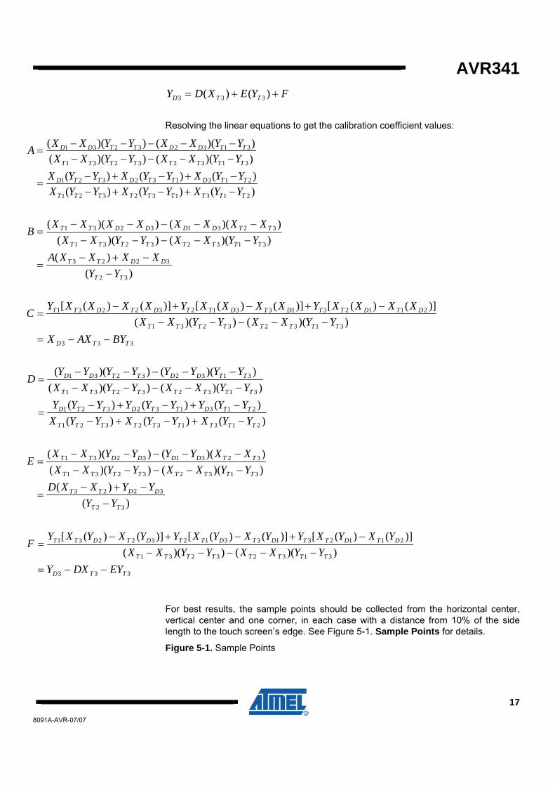
FYEXDY TTD ++= )()( 333
Resolving the linear equations to get the calibration coefficient values:
)()()()()()(
))(())(())(())((
213132321
213132321
31323231
31323231
TTTTTTTTT
TTDTTDTTD
TTTTTTTT
TTDDTTDD
YYXYYXYYXYYXYYXYYXYYXXYYXXYYXXYYXXA
−+−+−−+−+−
=
−−−−−−−−−−
=
)()(
))(())(())(())((
32
3223
31323231
32313231
TT
DDTT
TTTTTTTT
TTDDDDTT
YYXXXXA
YYXXYYXXXXXXXXXX
B
−−+−
=
−−−−−−−−−−
=
333
31323231
211231331232231
))(())(()]()([)]()([)]()([
TTD
TTTTTTTT
DTDTTDTDTTDTDTT
BYAXXYYXXYYXX
XXXXYXXXXYXXXXYC
−−=−−−−−
−+−+−=
)()()()()()())(())((
))(())((
213132321
213132321
31323231
31323231
TTTTTTTTT
TTDTTDTTD
TTTTTTTT
TTDDTTDD
YYXYYXYYXYYYYYYYYYYYXXYYXX
YYYYYYYYD
−+−+−−+−+−
=
−−−−−−−−−−
=
)()(
))(())(())(())((
32
3223
31323231
32313231
TT
DDTT
TTTTTTTT
TTDDDDTT
YYYYXXD
YYXXYYXXXXYYYYXX
E
−−+−
=
−−−−−−−−−−
=
333
31323231
211231331232231
))(())(()]()([)]()([)]()([
TTD
TTTTTTTT
DTDTTDTDTTDTDTT
EYDXYYYXXYYXX
YXYXYYXYXYYXYXYF
−−=−−−−−
−+−+−=
For best results, the sample points should be collected from the horizontal center, vertical center and one corner, in each case with a distance from 10% of the side length to the touch screen’s edge. See Figure 5-1. Sample Points for details.
Figure 5-1. Sample Points
17
8091A-AVR-07/07

18 AVR341
It is possible, but not necessary to calculate the calibration coefficients every time the device is powered on. For demonstration purposes it is sufficient to do this once, and store the values in EEPROM, for example. The “Start Flag” can be used as indicator for a power-up, in order to start this one-time calibration process.
Typically calibration is done once and the coefficients are stored into a non volatile memory. However it might be essential over a longer period of time to do a recalibration due to the impact of temperature, humidity and aging (“drift”).
5.2 Interpretation of touch motions As an overlay for a display, a touch screen uses normally absolute coordinates, so that the operation of the system can be done with clicks only. Additional features like dragging or drawing require an interpretation of the touch screen data to distinguish between clicks and movements. In this case, the “Touch Flag” and the “End Flag” are very helpful. A simple click can be defined as the combination of the Touch Flag, one or more set of coordinates and the End Flag within a narrow time window, e.g. 200ms.
Up to the expiration of this interval, all acquired coordinates can be directly used to set the cursor. By the end of the 200ms, the higher level software has to verify if an End Flag was received. If so, the input can be interpreted as click. Otherwise it is most likely a movement, hence continue positioning the cursor using new measured touch screen data.
8091A-AVR-07/07
Disclaimer Headquarters International
Atmel Corporation 2325 Orchard Parkway San Jose, CA 95131 USA Tel: 1(408) 441-0311 Fax: 1(408) 487-2600
Atmel Asia Room 1219 Chinachem Golden Plaza 77 Mody Road Tsimshatsui East Kowloon Hong Kong Tel: (852) 2721-9778 Fax: (852) 2722-1369
Product Contact
Atmel Europe Le Krebs 8, Rue Jean-Pierre Timbaud BP 309 78054 Saint-Quentin-en-Yvelines Cedex France Tel: (33) 1-30-60-70-00 Fax: (33) 1-30-60-71-11
Atmel Japan 9F, Tonetsu Shinkawa Bldg. 1-24-8 Shinkawa Chuo-ku, Tokyo 104-0033 Japan Tel: (81) 3-3523-3551 Fax: (81) 3-3523-7581
Web Site www.atmel.com
Technical Support [email protected]
Sales Contact www.atmel.com/contacts
Literature Request www.atmel.com/literature
Disclaimer: The information in this document is provided in connection with Atmel products. No license, express or implied, by estoppel or otherwise, to any intellectual property right is granted by this document or in connection with the sale of Atmel products. EXCEPT AS SET FORTH IN ATMEL’S TERMS AND CONDITIONS OF SALE LOCATED ON ATMEL’S WEB SITE, ATMEL ASSUMES NO LIABILITY WHATSOEVER AND DISCLAIMS ANY EXPRESS, IMPLIED OR STATUTORY WARRANTY RELATING TO ITS PRODUCTS INCLUDING, BUT NOT LIMITED TO, THE IMPLIED WARRANTY OF MERCHANTABILITY, FITNESS FOR A PARTICULAR PURPOSE, OR NON-INFRINGEMENT. IN NO EVENT SHALL ATMEL BE LIABLE FOR ANY DIRECT, INDIRECT, CONSEQUENTIAL, PUNITIVE, SPECIAL OR INCIDENTAL DAMAGES (INCLUDING, WITHOUT LIMITATION, DAMAGES FOR LOSS OF PROFITS, BUSINESS INTERRUPTION, OR LOSS OF INFORMATION) ARISING OUT OF THE USE OR INABILITY TO USE THIS DOCUMENT, EVEN IF ATMEL HAS BEEN ADVISED OF THE POSSIBILITY OF SUCH DAMAGES. Atmel makes no representations or warranties with respect to the accuracy or completeness of the contents of this document and reserves the right to make changes to specifications and product descriptions at any time without notice. Atmel does not make any commitment to update the information contained herein. Unless specifically provided otherwise, Atmel products are not suitable for, and shall not be used in, automotive applications. Atmel’s products are not intended, authorized, or warranted for use as components in applications intended to support or sustain life. © 2007 Atmel Corporation. All rights reserved. Atmel®, logo and combinations thereof, and others, are the registered trademarks or trademarks of Atmel Corporation or its subsidiaries. Other terms and product names may be trademarks of others.
8091A-AVR-07/07