avid® symphony™ color correction guideresources.avid.com/supportfiles/attach/symcc_v4_7.pdf ·...
TRANSCRIPT

m a k e m a n a g e m ove | m e d i a ™ Avid ®
Avid® Symphony™
Color Correction Guide
Copyright and DisclaimerProduct specifications are subject to change without notice and do not represent a commitment on the part of Avid Technology, Inc. The software described in this document is furnished under a license agreement. You can obtain a copy of that license by visiting Avid's Web site at www.avid.com. The terms of that license are also available in the product in the same directory as the software. The software may not be reverse assembled and may be used or copied only in accordance with the terms of the license agreement. It is against the law to copy the software on any medium except as specifically allowed in the license agreement. Avid products or portions thereof are protected by one or more of the following United States patents: 4,746,994; 4,970,663; 5,045,940; 5,267,351; 5,309,528; 5,355,450; 5,396,594; 5,440,348; 5,452,378; 5,467,288; 5,513,375; 5,528,310; 5,557,423; 5,568,275; 5,577,190; 5,584,006; 5,640,601; 5,644,364; 5,654,737; 5,715,018; 5,724,605; 5,726,717; 5,729,673; 5,745,637; 5,752,029; 5,754,851; 5,799,150; 5,812,216; 5,852,435; 5,883,670; 5,905,841; 5,929,836; 5,929,942; 5,930,445; 5,946,445; 5,987,501; 5,995,115; 6,016,152; 6,018,337; 6,023,531; 6,035,367; 6,038,573; 6,058,236; 6,061,758; 6,091,778; 6,105,083; 6,118,444; 6,128,001; 6,130,676; 6,134,607; 6,137,919; 6,141,007; 6,141,691; 6,157,929; 6,198,477; 6,201,531; 6,211,869; 6,223,211; 6,239,815; 6,249,280; 6,269,195; 6,301,105; 6,317,158; 6,317,515; 6,327,253; 6,330,369; 6,351,557; 6,353,862; 6,357,047; 6,392,710; 6,404,435; 6,407,775; 6,417,891; 6,426,778; D396,853; D398,912. Additional U.S. and foreign patents pending. No part of this document may be reproduced or transmitted in any form or by any means, electronic or mechanical, including photocopying and recording, for any purpose without the express written permission of Avid Technology, Inc.
Copyright © 2003 Avid Technology, Inc. and its licensors. All rights reserved. Printed in USA.
The following disclaimer is required by Apple Computer, Inc.APPLE COMPUTER, INC. MAKES NO WARRANTIES WHATSOEVER, EITHER EXPRESS OR IMPLIED, REGARDING THIS PRODUCT, INCLUDING WARRANTIES WITH RESPECT TO ITS MERCHANTABILITY OR ITS FITNESS FOR ANY PARTICULAR PURPOSE. THE EXCLUSION OF IMPLIED WARRANTIES IS NOT PERMITTED BY SOME STATES. THE ABOVE EXCLUSION MAY NOT APPLY TO YOU. THIS WARRANTY PROVIDES YOU WITH SPECIFIC LEGAL RIGHTS. THERE MAY BE OTHER RIGHTS THAT YOU MAY HAVE WHICH VARY FROM STATE TO STATE.
The following disclaimer is required by Sam Leffler and Silicon Graphics, Inc. for the use of their TIFF library:Copyright © 1988–1997 Sam Leffler Copyright © 1991–1997 Silicon Graphics, Inc.
Permission to use, copy, modify, distribute, and sell this software [i.e., the TIFF library] and its documentation for any purpose is hereby granted without fee, provided that (i) the above copyright notices and this permission notice appear in all copies of the software and related documentation, and (ii) the names of Sam Leffler and Silicon Graphics may not be used in any advertising or publicity relating to the software without the specific, prior written permission of Sam Leffler and Silicon Graphics.
THE SOFTWARE IS PROVIDED “AS-IS” AND WITHOUT WARRANTY OF ANY KIND, EXPRESS, IMPLIED OR OTHERWISE, INCLUDING WITHOUT LIMITATION, ANY WARRANTY OF MERCHANTABILITY OR FITNESS FOR A PARTICULAR PURPOSE.
IN NO EVENT SHALL SAM LEFFLER OR SILICON GRAPHICS BE LIABLE FOR ANY SPECIAL, INCIDENTAL, INDIRECT OR CONSEQUENTIAL DAMAGES OF ANY KIND, OR ANY DAMAGES WHATSOEVER RESULTING FROM LOSS OF USE, DATA OR PROFITS, WHETHER OR NOT ADVISED OF THE POSSIBILITY OF DAMAGE, AND ON ANY THEORY OF LIABILITY, ARISING OUT OF OR IN CONNECTION WITH THE USE OR PERFORMANCE OF THIS SOFTWARE.
The following disclaimer is required by the Independent JPEG Group:Portions of this software are based on work of the Independent JPEG Group.
The following disclaimer is required by Paradigm Matrix:Portions of this software licensed from Paradigm Matrix.
The following disclaimer is required by Ray Sauers Associates, Inc.:“Install-It” is licensed from Ray Sauers Associates, Inc. End-User is prohibited from taking any action to derive a source code equivalent of “Install-It,” including by reverse assembly or reverse compilation, Ray Sauers Associates, Inc. shall in no event be liable for any damages resulting from reseller’s failure to perform reseller’s obligation; or any damages arising from use or operation of reseller’s products or the software; or any other damages, including but not limited to, incidental, direct, indirect, special or consequential Damages including lost profits, or damages resulting from loss of use or inability to use reseller’s products or the software for any reason including copyright or patent infringement, or lost data, even if Ray Sauers Associates has been advised, knew or should have known of the possibility of such damages.
The following disclaimer is required by Videomedia, Inc.:“Videomedia, Inc. makes no warranties whatsoever, either express or implied, regarding this product, including warranties with respect to its merchantability or its fitness for any particular purpose.”
“This software contains V-LAN ver. 3.0 Command Protocols which communicate with V-LAN ver. 3.0 products developed by Videomedia, Inc. and V-LAN ver. 3.0 compatible products developed by third parties under license from Videomedia, Inc. Use of this software will allow “frame accurate” editing control of applicable videotape recorder decks, videodisc recorders/players and the like.”
The following disclaimer is required by Altura Software, Inc. for the use of its Mac2Win software and Sample Source Code:©1993–1998 Altura Software, Inc.
The following disclaimer is required by Ultimatte Corporation:Certain real-time compositing capabilities are provided under a license of such technology from Ultimatte Corporation and are subject to copyright protection.
The following disclaimer is required by 3Prong.com Inc.:Certain waveform and vector monitoring capabilities are provided under a license from 3Prong.com Inc.
Attn. Government User(s). Restricted Rights LegendU.S. GOVERNMENT RESTRICTED RIGHTS. This Software and its documentation are “commercial computer software” or “commercial computer software documentation.” In the event that such Software or documentation is acquired by or on behalf of a unit or agency of the U.S. Government, all rights with respect to this Software and documentation are subject to the terms of the License Agreement, pursuant to FAR §12.212(a) and/or DFARS §227.7202-1(a), as applicable.
Trademarks888 I/O, AirPlay, AirSPACE, AirSPACE HD, AniMatte, AudioSuite, AudioVision, AutoSync, Avid, AVIDdrive, AVIDdrive Towers, AvidNet, AvidNetwork, AVIDstripe, Avid Unity, Avid Xpress, AVoption, AVX, CamCutter, ChromaCurve, ChromaWheel, DAE, D-Fi, D-fx, Digidesign, Digidesign Audio Engine, Digidesign Intelligent Noise Reduction, DigiDrive, DINR, D-Verb, Equinox, ExpertRender, FieldPak, Film Composer, FilmScribe, FluidMotion, HIIP, HyperSPACE, HyperSPACE HDCAM, IllusionFX, Image Independence, Intraframe, iS9, iS18, iS23, iS36, Lo-Fi, Magic Mask, make manage move | media, Marquee, Matador, Maxim, MCXpress, Media Composer, MediaDock, MediaDock Shuttle, Media Fusion, Media Illusion, MediaLog, Media Reader, Media Recorder, MEDIArray, MediaShare, Meridien, MetaSync, NaturalMatch, NetReview, NewsCutter, OMF, OMF Interchange, OMM, Open Media Framework, Open Media Management, ProEncode, Pro Tools, QuietDrive, Recti-Fi, rS9, rS18, Sci-Fi, Softimage, Sound Designer II, SPACE, SPACEShift, Symphony, Trilligent, UnityRAID, Vari-Fi, Video Slave Driver, VideoSPACE, and Xdeck are either registered trademarks or trademarks of Avid Technology, Inc. in the United States and/or other countries.
iNEWS, iNEWS ControlAir, and Media Browse are trademarks of iNews, LLC.
Adobe, Acrobat Reader, and Photoshop are either registered trademarks or trademarks of Adobe Systems Incorporated in the United States and/or other countries. Mac, Mac OS, and Macintosh are trademarks of Apple Computer, Inc., registered in the U.S. and other countries. QuickTime and the QuickTime logo are trademarks used under license from Apple Computer, Inc. The QuickTime logo is registered in the U.S. and other countries. Windows is either a registered trademark or trademark of Microsoft Corporation in the United States and/or other countries. All other trademarks contained herein are the property of their respective owners.

Footage
Arri — Courtesy of Arri™/Fauer — John Fauer, Inc.Bell South “Anticipation” — Courtesy of Two Headed Monster — Tucker/Wayne Atlanta/GMS.Canyonlands — Courtesy of the National Park Service/Department of the Interior.Eco Challenge British Columbia — Courtesy of Eco Challenge Lifestyles, Inc., All Rights Reserved. Eco Challenge Morocco — Courtesy of Discovery Communications, Inc.It’s Shuttletime — Courtesy of BCP & Canadian Airlines. Nestlé Coffee Crisp — Courtesy of MacLaren McCann Canada. Saturn “Calvin Egg” — Courtesy of Cossette Communications. “Tigers: Tracking a Legend” — Courtesy of www.wildlifeworlds.com.Windhorse — Courtesy of Paul Wagner Productions.
GOT FOOTAGE?
Editors — Filmmakers — Special Effects Artists — Game Developers — Animators — Educators — Broadcasters — Content creators of every genre — Just finished an incredible project and want to share it with the world?
Send us your reels and we may use your footage in our show reel or demo!*
For a copy of our release and Avid’s mailing address, go to www.avid.com/footage.
*Note: Avid cannot guarantee the use of materials submitted.
Avid Symphony Color Correction Guide • Part 0130-05444-01 • February 2003
Contents
Using This Guide . . . . . . . . . . . . . . . . . . . . . . . . . . . . . . . . . . . . 13
Who Should Use This Guide . . . . . . . . . . . . . . . . . . . . . . . . . . . . . . . . . 13
About This Guide . . . . . . . . . . . . . . . . . . . . . . . . . . . . . . . . . . . . . . . . . . 14
Symbols and Conventions . . . . . . . . . . . . . . . . . . . . . . . . . . . . . . . . . . . 15
If You Need Help . . . . . . . . . . . . . . . . . . . . . . . . . . . . . . . . . . . . . . . . . . 17
Related Information . . . . . . . . . . . . . . . . . . . . . . . . . . . . . . . . . . . . . . . . 18
If You Have Documentation Comments . . . . . . . . . . . . . . . . . . . . . . . . . 19
How to Order Documentation . . . . . . . . . . . . . . . . . . . . . . . . . . . . . . . . . 19
Avid Educational Services . . . . . . . . . . . . . . . . . . . . . . . . . . . . . . . . . . . 19
Chapter 1 Color Correction in Avid Symphony . . . . . . . . . . . . . . . . . . . . 21
Introduction to Color Correction Mode . . . . . . . . . . . . . . . . . . . . . . . . . . 22
Making Color Corrections with Color Correction Mode . . . . . . . . . . 22
Understanding Source and Program Color Correction . . . . . . . . . . 23
Understanding Color Correction Relationships . . . . . . . . . . . . . . . . 24
Understanding Color Correction Groups . . . . . . . . . . . . . . . . . . . . . 24
Understanding Primary and Secondary Color Correction . . . . . . . . 25
Other Symphony Color Adjustment Tools . . . . . . . . . . . . . . . . . . . . . . . 26
Chapter 2 Understanding Color Correction Mode . . . . . . . . . . . . . . . . . . 29
Entering and Exiting Color Correction Mode . . . . . . . . . . . . . . . . . . . . . 30
Overview of the Color Correction Mode Display. . . . . . . . . . . . . . . . . . . 31
The Composer Window in Color Correction Mode . . . . . . . . . . . . . . . . . 32
Activating Monitors. . . . . . . . . . . . . . . . . . . . . . . . . . . . . . . . . . . . . . 32
Displaying Tracking Information. . . . . . . . . . . . . . . . . . . . . . . . . . . . 33

6
Displaying Images in Monitors . . . . . . . . . . . . . . . . . . . . . . . . . . . . . 33
Understanding Default Monitor Display . . . . . . . . . . . . . . . . . . . 33
Configuring Image Display in Monitors . . . . . . . . . . . . . . . . . . . 34
Splitting the Image Display in Monitors . . . . . . . . . . . . . . . . . . . 36
Hiding the Video in Monitors . . . . . . . . . . . . . . . . . . . . . . . . . . . 38
Displaying 16:9 Video in Monitors . . . . . . . . . . . . . . . . . . . . . . . 39
Using the Composer Window Buttons . . . . . . . . . . . . . . . . . . . . . . . 40
Using the Play Loop Button in Color Correction Mode . . . . . . . . . . . 42
Reviewing Color-Corrected Clips with the Edit Review
Button . . . . . . . . . . . . . . . . . . . . . . . . . . . . . . . . . . . . . . . . . . . . . . 42
Controlling Frame Display in the Composer Window . . . . . . . . . . . . 43
The Client Monitor in Color Correction Mode . . . . . . . . . . . . . . . . . . . . . 44
The Color Correction Tool. . . . . . . . . . . . . . . . . . . . . . . . . . . . . . . . . . . . 45
Understanding the Color Correction Tool Tabs . . . . . . . . . . . . . . . . 46
Working with the Source and Program Tabs . . . . . . . . . . . . . . . . . . 47
Using the Source Clip Name Relationship . . . . . . . . . . . . . . . . . . . . 49
Working with the Group and Subdividing Tabs. . . . . . . . . . . . . . . . . 50
Displaying a Group Tab . . . . . . . . . . . . . . . . . . . . . . . . . . . . . . . 50
Displaying a Subdividing Tab. . . . . . . . . . . . . . . . . . . . . . . . . . . 51
Associating Group and Subdividing Tabs with
Tab Buttons. . . . . . . . . . . . . . . . . . . . . . . . . . . . . . . . . . . . . . . 52
Understanding Interaction Between Color Correction
Groups. . . . . . . . . . . . . . . . . . . . . . . . . . . . . . . . . . . . . . . . . . . . . . 53
Working with the Enable Buttons . . . . . . . . . . . . . . . . . . . . . . . . . . . 55
Turning Controls On or Off . . . . . . . . . . . . . . . . . . . . . . . . . . . . . 55
Resetting Controls . . . . . . . . . . . . . . . . . . . . . . . . . . . . . . . . . . . 55
Understanding Interaction Between Enable Buttons . . . . . . . . . 56
Using the Color Correction Tool Buttons . . . . . . . . . . . . . . . . . . . . . 57
Customizing the Color Correction Tool. . . . . . . . . . . . . . . . . . . . . . . 58
Understanding 10-bit Units . . . . . . . . . . . . . . . . . . . . . . . . . . . . . . . . 64
Adding Comments to Color Correction Effects . . . . . . . . . . . . . . . . . 64
Working with Color Correction Effect Templates . . . . . . . . . . . . . . . . . . 66
Understanding How Color Correction Effect Templates
Save Settings . . . . . . . . . . . . . . . . . . . . . . . . . . . . . . . . . . . . . . . . 67
7
Using Automatic Effect Templates. . . . . . . . . . . . . . . . . . . . . . . . . . 68
Saving a Color Correction Effect Template to a Bin . . . . . . . . . . . . 70
Saving a Color Correction Effect Template to a Bucket. . . . . . . . . . 71
Applying Color Correction Effect Templates . . . . . . . . . . . . . . . . . . 72
Working with Color Correction Effect Templates in the
Effect Palette . . . . . . . . . . . . . . . . . . . . . . . . . . . . . . . . . . . . . . . . 73
Displaying Color Correction Information in the Timeline . . . . . . . . . . . . 74
Chapter 3 Performing Color Corrections . . . . . . . . . . . . . . . . . . . . . . . . . 77
General Workflow for Making Color Corrections . . . . . . . . . . . . . . . . . . 78
Using the Color Match Control . . . . . . . . . . . . . . . . . . . . . . . . . . . . . . . . 80
Making a Correction with the Color Match Control . . . . . . . . . . . . . 81
Selecting Match Type Options . . . . . . . . . . . . . . . . . . . . . . . . . . . . . 83
Understanding NaturalMatch . . . . . . . . . . . . . . . . . . . . . . . . . . . . . . 88
Color Match Example Using NaturalMatch . . . . . . . . . . . . . . . . . . . 88
Saving Custom Colors to a Bin . . . . . . . . . . . . . . . . . . . . . . . . . . . . 90
Getting RGB Information Using the Color Match Control . . . . . . . . 91
The HSL (Hue, Saturation, Luminance) Group . . . . . . . . . . . . . . . . . . . 91
Working with the Controls Tab. . . . . . . . . . . . . . . . . . . . . . . . . . . . . 92
Making Corrections Using the Controls Tab . . . . . . . . . . . . . . . 93
Using the HSL Sliders . . . . . . . . . . . . . . . . . . . . . . . . . . . . . . . . 94
Controls Tab Controls . . . . . . . . . . . . . . . . . . . . . . . . . . . . . . . . 95
Working with the Hue Offsets Tab . . . . . . . . . . . . . . . . . . . . . . . . . . 97
Understanding the Hue Offsets Tab . . . . . . . . . . . . . . . . . . . . . 97
Understanding the Hue Offsets Color Wheel . . . . . . . . . . . . . . 99
Making Corrections Using the Hue Offsets Tab . . . . . . . . . . . 101
Moving the Color Wheel Crosshair Pointers . . . . . . . . . . . . . . 102
Examples of Hue Offsets Settings. . . . . . . . . . . . . . . . . . . . . . 103
Working with the Luma Ranges Tab . . . . . . . . . . . . . . . . . . . . . . . 105
Understanding the Luma Ranges Graph. . . . . . . . . . . . . . . . . 106
Adjusting Luminance Ranges . . . . . . . . . . . . . . . . . . . . . . . . . 108
Manipulating Luminance Range Curves . . . . . . . . . . . . . . . . . 109
Examples of Three-Tone Previews . . . . . . . . . . . . . . . . . . . . . 109
8
The Channels Group. . . . . . . . . . . . . . . . . . . . . . . . . . . . . . . . . . . . . . . 111
Making Corrections Using the Channels Tab . . . . . . . . . . . . . . . . . 112
Using the Channel Blending Pane . . . . . . . . . . . . . . . . . . . . . . . . . 113
Considerations When Working with Color Components. . . . . . . . . 115
Examples of Channel Blending Settings . . . . . . . . . . . . . . . . . . . . 116
The Levels Group . . . . . . . . . . . . . . . . . . . . . . . . . . . . . . . . . . . . . . . . . 117
Understanding Input and Output Levels Adjustments . . . . . . . . . . 119
Examples of Black Point Input and Output Adjustments . . . . . 119
Examples of Gray Point Input and Output Adjustments. . . . . . 122
Making Corrections Using the Levels Tab . . . . . . . . . . . . . . . . . . . 124
Working with the Levels Tab Controls . . . . . . . . . . . . . . . . . . . . . . 126
Understanding Histograms. . . . . . . . . . . . . . . . . . . . . . . . . . . . 126
Using the Histogram Controls . . . . . . . . . . . . . . . . . . . . . . . . . 128
Using the Text Boxes . . . . . . . . . . . . . . . . . . . . . . . . . . . . . . . . 129
Understanding Curves . . . . . . . . . . . . . . . . . . . . . . . . . . . . . . . 130
Using the Curve Graph in the Levels Tab . . . . . . . . . . . . . . . . 132
Working with the Composite and Luma Tabs . . . . . . . . . . . . . 132
Examples of Levels Adjustments . . . . . . . . . . . . . . . . . . . . . . . 133
The Curves Group. . . . . . . . . . . . . . . . . . . . . . . . . . . . . . . . . . . . . . . . . 136
Making Corrections Using the Curves Tab. . . . . . . . . . . . . . . . . . . 136
Adjusting Curves . . . . . . . . . . . . . . . . . . . . . . . . . . . . . . . . . . . . . . 137
Curves and the Color Match Control . . . . . . . . . . . . . . . . . . . . . . . 140
Examples of Curve Adjustments. . . . . . . . . . . . . . . . . . . . . . . . . . . 142
The Secondary Group. . . . . . . . . . . . . . . . . . . . . . . . . . . . . . . . . . . . . . 149
Understanding Secondary Color Correction . . . . . . . . . . . . . . . . . . 150
Secondary Color Correction Workflow . . . . . . . . . . . . . . . . . . . . . . 151
Understanding Secondary Color Correction Vectors . . . . . . . . . . . 153
Standard and Custom Vectors . . . . . . . . . . . . . . . . . . . . . . . . . 153
Vector Display in Color Wheels . . . . . . . . . . . . . . . . . . . . . . . . 153
Customizing a Vector Display . . . . . . . . . . . . . . . . . . . . . . . . . 157
Understanding the Selected Vectors Panel . . . . . . . . . . . . . . . . . . 159
Selecting Vectors . . . . . . . . . . . . . . . . . . . . . . . . . . . . . . . . . . . . . . 160
Enabling and Disabling Vectors . . . . . . . . . . . . . . . . . . . . . . . . . . . 161
9
Resetting Vectors. . . . . . . . . . . . . . . . . . . . . . . . . . . . . . . . . . . . . . 161
Adjusting Input Vector Values . . . . . . . . . . . . . . . . . . . . . . . . . . . . 162
Repositioning Vectors in the Color Wheel . . . . . . . . . . . . . . . . 163
Using the Input Vector Sliders . . . . . . . . . . . . . . . . . . . . . . . . . 163
Examples of Softness Adjustments . . . . . . . . . . . . . . . . . . . . . 165
Using the Color Selection Buttons . . . . . . . . . . . . . . . . . . . . . . . . . 167
Defining a Vector with the Syringe . . . . . . . . . . . . . . . . . . . . . 168
Refining a Vector Definition with the Add to Selection and
Subtract from Selection Buttons. . . . . . . . . . . . . . . . . . . . . . 169
Isolating the Selected Vector . . . . . . . . . . . . . . . . . . . . . . . . . . . . . 170
Adjusting Output Vector Values . . . . . . . . . . . . . . . . . . . . . . . . . . . 173
Using the Color Match Control for Secondary Corrections . . . . . . 174
Making a Secondary Correction with the Color Match Control
and the Syringe . . . . . . . . . . . . . . . . . . . . . . . . . . . . . . . . . . 175
Making a Secondary Color Correction with the Color Match
Control Only . . . . . . . . . . . . . . . . . . . . . . . . . . . . . . . . . . . . . 175
Inverting a Vector. . . . . . . . . . . . . . . . . . . . . . . . . . . . . . . . . . . . . . 176
Examples of Inverted and Isolated Images . . . . . . . . . . . . . . . . . . 177
Understanding How Multiple Vectors Interact . . . . . . . . . . . . . . . . 179
Playback Considerations for Secondary Color Correction. . . . . . . 179
Playing Secondary Color Corrections and 3D Effects . . . . . . . 179
Playing Secondary Color Corrections and Two-Stream
Effects . . . . . . . . . . . . . . . . . . . . . . . . . . . . . . . . . . . . . . . . . 180
Working with the Waveform Monitors and Vectorscope Monitor . . . . . 181
Using the Waveform and Vectorscope Information . . . . . . . . . . . . 190
Using the Color Correction Effect in the Effect Palette. . . . . . . . . . . . . 191
Applying a Color Correction Effect from the Effect Palette . . . . . . 192
Working with an Effect Palette Color Correction Effect . . . . . . . . . 194
Chapter 4 Managing Color-Corrected Sequences . . . . . . . . . . . . . . . . . 195
Updating Color-Corrected Sequences . . . . . . . . . . . . . . . . . . . . . . . . . 196
Merging Color-Corrected Sequences. . . . . . . . . . . . . . . . . . . . . . . . . . 198
Using the Merge Correction Command . . . . . . . . . . . . . . . . . . . . . 199
Color Correction Merging Example . . . . . . . . . . . . . . . . . . . . . . . . 201
10
Flattening Color-Corrected Sequences. . . . . . . . . . . . . . . . . . . . . . . . . 204
Removing Color Corrections . . . . . . . . . . . . . . . . . . . . . . . . . . . . . . . . . 206
Chapter 5 Color Correction Techniques . . . . . . . . . . . . . . . . . . . . . . . . . 209
Guiding Principles for Color Correction. . . . . . . . . . . . . . . . . . . . . . . . . 210
Goals of Color Correction: Restoration and Adaptation . . . . . . . . . 210
Restoring the Original Look . . . . . . . . . . . . . . . . . . . . . . . . . . . 210
Adapting the Original Look. . . . . . . . . . . . . . . . . . . . . . . . . . . . 211
Stages of Color Correction . . . . . . . . . . . . . . . . . . . . . . . . . . . . . . . 212
Correcting Tonal Range . . . . . . . . . . . . . . . . . . . . . . . . . . . . . . 213
Neutralizing Color. . . . . . . . . . . . . . . . . . . . . . . . . . . . . . . . . . . 214
Achieving Shot-to-Shot Consistency . . . . . . . . . . . . . . . . . . . . 216
Achieving a Final Look . . . . . . . . . . . . . . . . . . . . . . . . . . . . . . . 216
Examples of Color Correction Problems . . . . . . . . . . . . . . . . . . . . . . . . 217
Example 1. . . . . . . . . . . . . . . . . . . . . . . . . . . . . . . . . . . . . . . . . . . . 218
Example 2. . . . . . . . . . . . . . . . . . . . . . . . . . . . . . . . . . . . . . . . . . . . 222
Example 3. . . . . . . . . . . . . . . . . . . . . . . . . . . . . . . . . . . . . . . . . . . . 226
Chapter 6 Spot Color Correction . . . . . . . . . . . . . . . . . . . . . . . . . . . . . . . 231
Using the Spot Color Correction Effect . . . . . . . . . . . . . . . . . . . . . . . . . 232
Making Corrections Using the Spot Color Correction Effect. . . . . . 234
Spot Color Correction Parameters . . . . . . . . . . . . . . . . . . . . . . . . . 235
Using Paint Effect Modes for Color Adjustment . . . . . . . . . . . . . . . . . . 237
Chapter 7 Safe Color Limiting and Warning . . . . . . . . . . . . . . . . . . . . . . 241
Overview of Safe Color Limits. . . . . . . . . . . . . . . . . . . . . . . . . . . . . . . . 242
Setting Safe Color Limits. . . . . . . . . . . . . . . . . . . . . . . . . . . . . . . . . . . . 243
Understanding the Graphical View of Safe Color Settings . . . . . . . . . . 247
Understanding Safe Color Warnings. . . . . . . . . . . . . . . . . . . . . . . . . . . 249
Safe Color Warnings in the Monitors . . . . . . . . . . . . . . . . . . . . . . . 249
Safe Color Warnings on Histograms . . . . . . . . . . . . . . . . . . . . . . . 252
Safe Color Warnings in the Color Match Control . . . . . . . . . . . . . . 252
Safe Color Warnings in the Secondary Group Tab . . . . . . . . . . . . 253
Adjusting Color Levels to Achieve Safe Limits . . . . . . . . . . . . . . . . 253

11
Safe Color Behavior with Effect and DSK Colors . . . . . . . . . . . . . . . . . 254
Safe Color Behavior with Effect Colors . . . . . . . . . . . . . . . . . . . . . 254
Safe Color Behavior with DSK Titles and Graphics . . . . . . . . . . . . 256
Safe Color Limits with Waveform and Vectorscope Information . . . . . 257
Index . . . . . . . . . . . . . . . . . . . . . . . . . . . . . . . . . . . . . . . . . . . . . 261

12
Tables
Table 1 Source Menu Commands. . . . . . . . . . . . . . . . . . . . . . . . . 35
Table 2 Composer Window Buttons . . . . . . . . . . . . . . . . . . . . . . . 40
Table 3 Source and Program Relationships . . . . . . . . . . . . . . . . . 48
Table 4 Correction Mode Settings Options . . . . . . . . . . . . . . . . . . 59
Table 5 HSL Group (Controls Tab) Match Type Options . . . . . . . 83
Table 6 HSL Group (Hue Offsets Tab) Match Type Options. . . . . 84
Table 7 Channels Tab Match Type Options . . . . . . . . . . . . . . . . . 85
Table 8 Levels Tab Match Type Options. . . . . . . . . . . . . . . . . . . . 86
Table 9 Curves Tab Match Type Options . . . . . . . . . . . . . . . . . . . 86
Table 10 Secondary Tab Match Type Options . . . . . . . . . . . . . . . . 87
Table 11 Brightness Subdividing Tabs for the HSL Group . . . . . . . 93
Table 12 Controls Tab Controls . . . . . . . . . . . . . . . . . . . . . . . . . . . 95
Table 13 Hue Offsets Color Wheel Crosshair Pointers . . . . . . . . . . 99
Table 14 Component Type Options in the Channels Tab . . . . . . . 114
Table 15 Secondary Color Correction Vector Display Options . . . 158
Table 16 Input Vector Sliders . . . . . . . . . . . . . . . . . . . . . . . . . . . . 164
Table 17 Waveform and Vectorscope Commands . . . . . . . . . . . . 182
Table 18 Spot Color Correction Parameters . . . . . . . . . . . . . . . . . 235
Table 19 Paint Effect Modes for Color Adjustment . . . . . . . . . . . . 238
Table 20 Safe Color Settings Options . . . . . . . . . . . . . . . . . . . . . . 245
Table 21 Safe Color Warning Indicators . . . . . . . . . . . . . . . . . . . . 250
Table 22 Safe Color Limits in Waveform Displays . . . . . . . . . . . . 259

Using This Guide
Your Avid® Symphony™ system uses the 10-bit Advanced Color Correction Engine to process multiple color adjustments in real time.
This guide provides information on the color correction features of Avid Symphony. Using these features, you can easily make adjustments to color that will improve the appearance of the video material in your projects.
If your project workflow normally includes traditional color correction, your Symphony system’s color correction tools can reduce or even eliminate the need for such procedures. If your workflow has not allowed for extensive color correction in the past, your Symphony system’s color correction tools can make possible a new level of color-finishing quality.
n Your system might not contain certain features that are described in your documentation. Our documents describe all features regardless of which model you purchased.
Who Should Use This Guide
This guide is intended for all Avid Symphony users, from beginning to advanced.
Using This Guide
14
About This Guide
This guide is designed to provide you with all the information you need to make precise color adjustments using your Symphony system, including complete explanations of all the Symphony color correction tools. The guide leads you through all color correction procedures with task-oriented instructions, illustrated in full color for a more realistic presentation of the on-screen elements and images you will encounter. Many examples of color correction techniques and typical color correction problems help you understand what to look for when you are correcting color in a sequence. Thorough cross-references to other parts of your Avid Symphony documentation make it easy for you to find additional information.
This guide is also available as part of the Avid Symphony Online Publications CD-ROM. The online version of the guide displays on your computer screen and offers advanced navigation and search features. It includes all the full-color illustrations that appear in the printed version.
n If you are reading a hardcopy version of this document, you will find it useful to view the color images in the Help or in the online version of this document on the online publications CD-ROM.
The Contents lists all topics included in the book. They are presented with the following overall structure:
• Chapter 1 provides a general introduction to the organization of Color Correction mode in Symphony and summarizes all the other color adjustment tools.
• Chapter 2 describes the Color Correction mode display in detail and explains how to control, customize, and move around in Color Correction mode.
• Chapter 3 provides step-by-step instructions for all the color adjustment operations you can perform using the Color Correction tool, together with conceptual information and examples to help you understand the differences between the various color correction controls.
• Chapter 4 explains how to manage and update sequences once they include color correction information.

Symbols and Conventions
15
• Chapter 5 provides guidelines for approaching the task of color correction, examples of typical color correction problems, and discussions of how to solve those problems using your Symphony system’s color correction tools. This chapter is especially useful as an introduction to color correction for Avid users who have little prior experience making color adjustments.
• Chapter 6 explains the tools available in your Symphony system for making color adjustments to parts of an image that you select using drawing tools.
• Chapter 7 explains the Safe Color warning and limiting functions of your Symphony system.
• The Index helps you quickly locate specific topics.
Symbols and Conventions
Unless noted otherwise, the material in this document applies to the Windows® 2000 and Mac OS® X operating systems. When the text applies to a specific operating system, it is marked as follows:
• (Windows) or (Windows only) means the information applies to the Windows 2000 operating system.
• (Macintosh) or (Macintosh only) means the information applies to the Mac OS X operating system.
The majority of screen shots in this document were captured on a Windows 2000 system, but the information applies to both Windows 2000 and Mac OS X systems. Where differences exist, both Windows 2000 and Mac OS X screen shots are shown.
In this document, the term “editing guide” refers to the Avid Symphony Editing Guide. The term “input and output guide” refers to the Avid Symphony Input and Output Guide. The term “effects guide” refers to the Avid Symphony Effects Guide. The term “online publications CD-ROM” refers to the Avid Symphony Online Publications CD-ROM.
Using This Guide
16
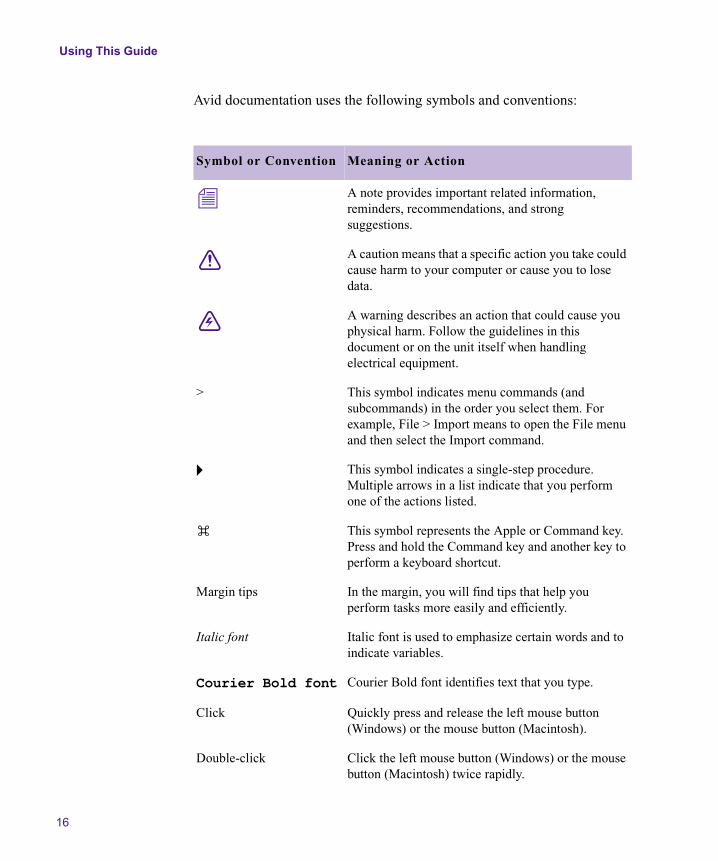
Avid documentation uses the following symbols and conventions:
Symbol or Convention Meaning or Action
n A note provides important related information, reminders, recommendations, and strong suggestions.
c A caution means that a specific action you take could cause harm to your computer or cause you to lose data.
w A warning describes an action that could cause you physical harm. Follow the guidelines in this document or on the unit itself when handling electrical equipment.
> This symbol indicates menu commands (and subcommands) in the order you select them. For example, File > Import means to open the File menu and then select the Import command.
t This symbol indicates a single-step procedure. Multiple arrows in a list indicate that you perform one of the actions listed.
k This symbol represents the Apple or Command key. Press and hold the Command key and another key to perform a keyboard shortcut.
Margin tips In the margin, you will find tips that help you perform tasks more easily and efficiently.
Italic font Italic font is used to emphasize certain words and to indicate variables.
Courier Bold font Courier Bold font identifies text that you type.
Click Quickly press and release the left mouse button (Windows) or the mouse button (Macintosh).
Double-click Click the left mouse button (Windows) or the mouse button (Macintosh) twice rapidly.
If You Need Help
17
If You Need Help
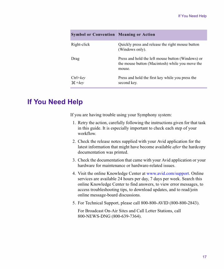
If you are having trouble using your Symphony system:
1. Retry the action, carefully following the instructions given for that task in this guide. It is especially important to check each step of your workflow.
2. Check the release notes supplied with your Avid application for the latest information that might have become available after the hardcopy documentation was printed.
3. Check the documentation that came with your Avid application or your hardware for maintenance or hardware-related issues.
4. Visit the online Knowledge Center at www.avid.com/support. Online services are available 24 hours per day, 7 days per week. Search this online Knowledge Center to find answers, to view error messages, to access troubleshooting tips, to download updates, and to read/join online message-board discussions.
5. For Technical Support, please call 800-800-AVID (800-800-2843).
For Broadcast On-Air Sites and Call Letter Stations, call800-NEWS-DNG (800-639-7364).
Right-click Quickly press and release the right mouse button (Windows only).
Drag Press and hold the left mouse button (Windows) or the mouse button (Macintosh) while you move the mouse.
Ctrl+keyk+key
Press and hold the first key while you press the second key.
Symbol or Convention Meaning or Action

Using This Guide
18
Related Information
The following documents provide more information about Avid Symphony:
• Avid Symphony Release Notes
• Avid Symphony Site Preparation Guide for the Windows 2000 Professional Operating System
• Avid Symphony Site Preparation Guide for the Mac OS X Operating System
• Avid Products Getting Started Guide
• Avid Symphony Quick Reference
• Avid Symphony Editing Guide
• Avid Symphony Effects Guide
• Avid Symphony Input and Output Guide
• Avid Symphony and Composer Products Setup Guide for the Windows 2000 Professional Operating System
• Addendum for the Avid Symphony and Composer Products Setup Guide for the Windows 2000 Professional Operating System
• Avid Symphony and Composer Products Setup Guide for the Mac OS X Operating System
• Avid Symphony Online Publications CD-ROM
This online collection provides electronic versions of most documents listed in this section, as well as documents for related Avid applications. You can view these documents with Adobe®
Acrobat® Reader®, which you can install from the CD-ROM.
• Avid Symphony Help
The Help system provides all the information included in the Avid Symphony Editing Guide, the Avid Symphony Input and Output Guide, the Avid Symphony Effects Guide, and the Avid Symphony Color Correction Guide supplied with your system. The Help operates in a Web browser. To open the Help, select Help > Symphony Help in the Symphony application. For information on using Help, click the Using Help button in the Help system.
If You Have Documentation Comments
19
If You Have Documentation Comments
Avid Technology continuously seeks to improve its documentation. We value your comments about this guide, the Help, the Online Publications CD-ROM, and other Avid-supplied documentation.
Simply e-mail your documentation comments to Avid Technology at
Please include the title of the document, its part number, and the specific section you are commenting on in all correspondence.
How to Order Documentation
To order additional copies of this documentation from within the United States, call Avid Sales at 800-949-AVID (800-949-2843). If you are placing an order from outside the United States, contact your local Avid representative.
Avid Educational Services
For information on courses/schedules, training centers, certifications, courseware, and books, please visit www.avid.com/training or call Avid Sales at 800-949-AVID (800-949-2843).

Using This Guide
20
Chapter 1
Color Correction in Avid Symphony
Your Avid Symphony system includes a comprehensive set of tools for correcting and adjusting colors. These tools combine much of the capability familiar to professional colorists with easy-to-use controls that can be mastered quickly by film and video editors.
This chapter provides a conceptual introduction to Color Correction mode, the portion of your Symphony system that allows you to correct color across entire sequences. This chapter also summarizes other color adjustment features and tells you where to find more information about them.
• Introduction to Color Correction Mode
• Other Symphony Color Adjustment Tools
Chapter 1 Color Correction in Avid Symphony
22
Introduction to Color Correction Mode
You can perform color correction for your whole project using Color Correction mode. You can correct individual segments in a sequence or correct multiple segments at the same time by linking them in a variety of ways. You can select from several types of color correction controls, selecting the ones that work best for your project or that are most suitable for your working methods.
When you use Color Correction mode, having a basic understanding of how the color correction tool is organized and how your Symphony system applies color corrections is helpful. The following sections explain these basic concepts.
Making Color Corrections with Color Correction Mode
Color Correction mode works with video material once it has been edited into a sequence. You make color adjustments in Color Correction mode by selecting segments within a sequence and then altering their color values. Your Symphony system associates these adjustments with the sequence on which they are made and applies them in real time when the sequence is processed for playback.
The color corrections that you make in Color Correction mode do not cause any permanent change to clips in bins or to their associated media files. If you make a color adjustment to a clip in one sequence, that adjustment does not apply to the same clip in a different sequence.
When you edit new material into a sequence, you can update the sequence to apply existing color corrections automatically to the new material. For more information on working with color-corrected sequences, see Chapter 4.
Introduction to Color Correction Mode
23
Understanding Source and Program Color Correction
Color Correction mode allows you to work with two main levels of real-time color correction capability. These two levels provide distinct Source and Program color correction.
You can use Source color correction to compensate for color inconsistencies in your source material, such as differences in tapes and decks, differences in camera and lighting, and differences in film processing. You can also make detailed corrections to balance color and tone from shot to shot.
You can use Program color correction (normally at a later stage of your workflow) to adjust an entire sequence or a portion of a sequence, to give a program an overall look or make other final alterations to color.
This guide refers to making color corrections on the Source side and the Program side, a terminology that reflects the display of Source and Program controls on either side of the Color Correction tool.
This model mirrors one of the most common traditional color correction workflows, in which material receives one color correction pass to correct problems in source material (often at the time of a best-light telecine transfer) and another pass to create a finished look after final editing of your program.
Corrections made using the two levels of correction are applied together in real time when the fully corrected sequence plays back. The Source color correction is applied first to the uncorrected clip, and then the Program color correction is applied to the result of the Source color correction.
For example, you might lighten some shots during Source color correction to make them match other shots, and then choose to darken the whole sequence slightly during Program color correction. Shots that had been lightened in the Source color correction process would finally show the net result of both the Source lightening and the Program darkening adjustments.
Chapter 1 Color Correction in Avid Symphony
24
Understanding Color Correction Relationships
Color corrections often are made most efficiently to more than one segment at a time. For example, you might need to lighten all the material that was shot by one camera or to make a correction to every use of the material from one master clip. Color Correction mode allows you to set both Source and Program relationships to give you control over the scope of the corrections you make.
When you set a Source or Program relationship, you instruct your Symphony system to apply the adjustments that you make within one segment to other segments related to it in the sequence. On the Source side, these relationships are based on the clip from which the segment is taken or on the entire tape from which the segment is taken. On the Program side, these relationships are based on entire tracks in the sequence. You can also control the scope of color correction by marking IN and OUT points in your sequence. For more information on selecting Source and Program relationships, see “Working with the Source and Program Tabs” on page 47.
Understanding Color Correction Groups
Color Correction mode provides five main groups of color correction controls. Each group is available on both the Source side and the Program side.
You can make adjustments using just one group of controls or using any combination of groups. If you make adjustments in more than one group, you can turn each group on or off independently to control which adjustments are active. When Symphony processes the sequence for playback, it applies the adjustments from all the active groups together to create the final appearance of the sequence. For more information on the interaction between groups, see “Understanding Interaction Between Color Correction Groups” on page 53.

Introduction to Color Correction Mode
25
Each group uses a different kind of control for making adjustments. For example, the Channels group allows you to blend color channels in different proportions, while the Curves group allows you to manipulate points on a graph that control the relationship between input and output color.
Although the variations in the controls mean that some groups are especially well-suited to solving particular color problems, each group can be used successfully to make a wide range of adjustments. The choice of which group or groups to use is partly a matter of personal preference and the requirements of your project. Some users might switch from one group to another frequently, but many will become comfortable with one or two of the groups and use those for almost all their correction work. If you find one group of controls very difficult to understand and work with, you can almost always avoid that group and make all your color adjustments using the others. For more information on the individual color correction groups, see “Working with the Group and Subdividing Tabs” on page 50.
Understanding Primary and Secondary Color Correction
Four of the color correction groups — HSL, Channels, Levels, and Curves — perform primary color correction. Symphony applies primary color correction by considering every pixel in an image or every pixel within a specific luminance range in the image.
Primary color correction provides a great deal of power and flexibility. For example, you can define a primary correction so that it does not affect the darkest pixels in the image. You can also define a primary correction so that it alters the blue parts of an image substantially without distorting the red parts significantly. For more information, see “The HSL (Hue, Saturation, Luminance) Group” on page 91 and the subsequent discussions of the Channels, Levels, and Curves groups.
However, primary color correction does not allow you to define a color range within an image and limit the correction to that range alone. Such a limit is often useful when dealing with individual objects in images. For example, you might want to adjust the intense color of a very bright item of clothing without altering the other color values in the image in any way.

Chapter 1 Color Correction in Avid Symphony
26
The fifth color correction group — Secondary (Sec) — solves this problem by performing secondary color correction. Symphony applies secondary color correction to a range of pixels in an image that you define by specifying hue and saturation values. For example, you can make a secondary correction that changes only the bright blue pixels in an image. Secondary color correction allows you to quickly and easily adjust one range of color in an image without changing the rest of the image in any way. For more information, see “The Secondary Group” on page 149.
n You can also adjust the color of a specific object using the Spot Color Correction effect or the Paint Effect to define the object by drawing. For more information, see Chapter 6.
Other Symphony Color Adjustment Tools
In addition to the work you can do in Color Correction mode, you can use several other tools to correct and adjust colors at various stages of your project. Some of these tools are described in this guide; others are described in other parts of your Symphony documentation. The following is a summary of these tools with the locations of detailed information about them.
• When you digitize, you can make initial adjustments to the color of incoming video using the Video Input tool. For more information, see “Preparing for Video Input” in the chapter “Preparing to Digitize” in the input and output guide.
• You can create keyframeable color effects on individual segments in a sequence using the Color Effect. For more information, see “Image: Color Effect” in the chapter “2D Reference” in the effects guide.
• You can create color effects that are limited to specific areas of an image that you define with drawing tools in the Spot Color Correction effect or within certain modes in the Paint Effect. For more information, see Chapter 6.
Other Symphony Color Adjustment Tools
27
• You can make many adjustments to color within other 2D and 3D effects, including color control for keys, highlight and lowlight color, and border colors. For more information, see the effects guide.
• You can set safe limits for the colors that appear in your project and ask your Symphony system either to warn you when those limits are exceeded or to limit the colors automatically. For more information, see Chapter 7.

Chapter 1 Color Correction in Avid Symphony
28
Chapter 2
Understanding Color Correction Mode
Like other modes in your Symphony system, such as Trim mode and Effect mode, Color Correction mode reconfigures the Edit monitor display to provide a specialized interface. This chapter describes the Color Correction mode display and explains how to control and customize it.
• Entering and Exiting Color Correction Mode
• Overview of the Color Correction Mode Display
• The Composer Window in Color Correction Mode
• The Client Monitor in Color Correction Mode
• The Color Correction Tool
• Working with Color Correction Effect Templates
• Displaying Color Correction Information in the Timeline
Chapter 2 Understanding Color Correction Mode
30
Entering and Exiting Color Correction Mode
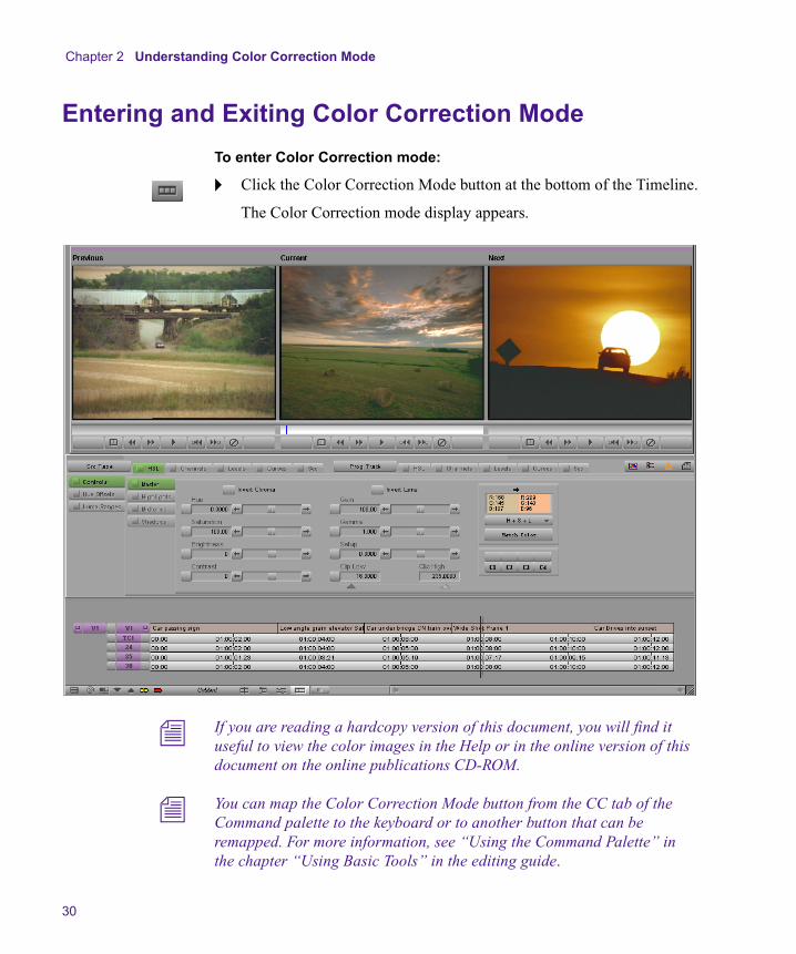
To enter Color Correction mode:
t Click the Color Correction Mode button at the bottom of the Timeline.
The Color Correction mode display appears.
n If you are reading a hardcopy version of this document, you will find it useful to view the color images in the Help or in the online version of this document on the online publications CD-ROM.
n You can map the Color Correction Mode button from the CC tab of the Command palette to the keyboard or to another button that can be remapped. For more information, see “Using the Command Palette” in the chapter “Using Basic Tools” in the editing guide.

Overview of the Color Correction Mode Display
31
To exit Color Correction mode and return to another mode, do one of the following:
t Click the appropriate mode button — Source/Record, Trim, or Effect.
Symphony replaces the Color Correction mode display with the display for the mode you selected.
t Make a selection from the Toolset menu.
Symphony replaces the Color Correction display with the toolset for the mode you selected.
Overview of the Color Correction Mode Display
The Color Correction mode display includes three windows:
• The Composer window, configured to a three-monitor view
For more information, see “The Composer Window in Color Correction Mode” on page 32.
• The Color Correction tool
For more information, see “The Color Correction Tool” on page 45.
• The Timeline, resized to accommodate the other elements of the color correction display
For more information, see “Displaying Color Correction Information in the Timeline” on page 74.
Color Correction mode also allows you to display several kinds of image information in the Client monitor. For more information, see “The Client Monitor in Color Correction Mode” on page 44.
The following sections describe the organization of these elements and explain how to navigate in them and how to customize them for your project needs.
Chapter 2 Understanding Color Correction Mode
32
The Composer Window in Color Correction Mode
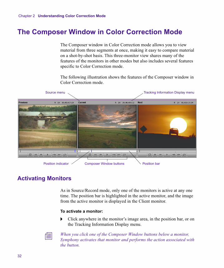
The Composer window in Color Correction mode allows you to view material from three segments at once, making it easy to compare material on a shot-by-shot basis. This three-monitor view shares many of the features of the monitors in other modes but also includes several features specific to Color Correction mode.
The following illustration shows the features of the Composer window in Color Correction mode.
Activating Monitors
As in Source/Record mode, only one of the monitors is active at any one time. The position bar is highlighted in the active monitor, and the image from the active monitor is displayed in the Client monitor.
To activate a monitor:
t Click anywhere in the monitor’s image area, in the position bar, or on the Tracking Information Display menu.
n When you click one of the Composer Window buttons below a monitor, Symphony activates that monitor and performs the action associated with the button.
Source menu
Composer Window buttons Position barPosition indicator
Tracking Information Display menu
The Composer Window in Color Correction Mode
33
Displaying Tracking Information
The Composer Window monitors in Color Correction mode have the same options for displaying tracking information that are available in other modes.
To display tracking information:
t Click the monitor’s Tracking Information Display menu, and then select the format you want from the menu.
By default, the Tracking Information Display menu shows no information until you select a tracking format.
n If you select the option in the Composer Settings dialog box for two information rows above the monitors, you can display two different types of tracking information in each monitor, just as you can in other modes.
For more information on tracking information display, see “Displaying Tracking Information” in the chapter “Viewing and Marking Footage” in the editing guide.
Displaying Images in Monitors
The default Color Correction display shows images from three adjacent segments in the Timeline. You can customize the display to show images from other parts of the sequence, to show specific images in a split-screen display, to hide the video, or to display wide-screen (16:9) video.
Understanding Default Monitor Display
By default, the center monitor shows the current segment (the segment the position indicator is on in the Timeline). The left monitor shows the previous segment (the segment before the current segment), and the right monitor shows the next segment (the segment after the current segment).
When you move in the sequence by clicking a Composer Window button or by placing the position indicator on a new segment in the Timeline, all three monitors update to maintain the same relationship between displayed segments.

Chapter 2 Understanding Color Correction Mode
34
The following illustrations show the default monitor display behavior.
Configuring Image Display in Monitors
You can configure each monitor to display those segments that are most useful for making comparisons in your project.
To configure the display in a monitor:
t Click the monitor’s Source menu, and select one of the options described in Table 1.
The position indicator is on segment B in the Timeline. The three monitors display segments A, B, and C.
Example 1
The position indicator has moved to segment C. All three monitors have updated so that they now display segments B, C, and D.
Example 2
The Composer Window in Color Correction Mode
35
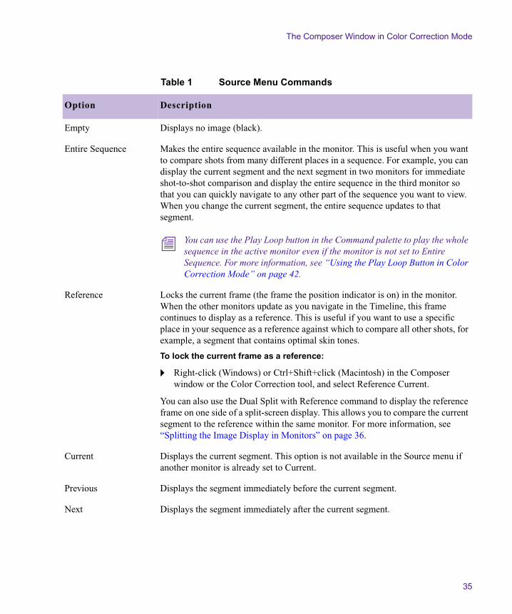
Table 1 Source Menu Commands
Option Description
Empty Displays no image (black).
Entire Sequence Makes the entire sequence available in the monitor. This is useful when you want to compare shots from many different places in a sequence. For example, you can display the current segment and the next segment in two monitors for immediate shot-to-shot comparison and display the entire sequence in the third monitor so that you can quickly navigate to any other part of the sequence you want to view. When you change the current segment, the entire sequence updates to that segment.
n You can use the Play Loop button in the Command palette to play the whole sequence in the active monitor even if the monitor is not set to Entire Sequence. For more information, see “Using the Play Loop Button in Color Correction Mode” on page 42.
Reference Locks the current frame (the frame the position indicator is on) in the monitor. When the other monitors update as you navigate in the Timeline, this frame continues to display as a reference. This is useful if you want to use a specific place in your sequence as a reference against which to compare all other shots, for example, a segment that contains optimal skin tones.
To lock the current frame as a reference:
t Right-click (Windows) or Ctrl+Shift+click (Macintosh) in the Composer window or the Color Correction tool, and select Reference Current.
You can also use the Dual Split with Reference command to display the reference frame on one side of a split-screen display. This allows you to compare the current segment to the reference within the same monitor. For more information, see “Splitting the Image Display in Monitors” on page 36.
Current Displays the current segment. This option is not available in the Source menu if another monitor is already set to Current.
Previous Displays the segment immediately before the current segment.
Next Displays the segment immediately after the current segment.

Chapter 2 Understanding Color Correction Mode
36
Splitting the Image Display in Monitors
You can configure a monitor so that it splits the screen to show the image before and after the current color correction adjustments are applied. You can also configure a monitor so that it splits the screen to show the currently selected reference image beside the image from the current segment.
To display uncorrected and corrected images in a split screen (Dual Split):
t Click the Dual Split button for the monitor you want to display the split screen.
The split-screen display appears in the monitor and in the Client monitor.
Second Previous Displays the segment two segments before the current segment (the segment the position indicator is on in the Timeline).
Second Next Displays the segment two segments after the current one.
Waveform and Vectorscope commands
• Quad Display
• RGB Histogram
• RGB Parade
• Vectorscope
• Y Waveform
• YC Waveform
• YCbCr Histogram
• YCbCr Parade
These commands configure the monitor as a Waveform monitor or a Vectorscope monitor. Symphony displays the information for the currently active monitor. For more information, see “Working with the Waveform Monitors and Vectorscope Monitor” on page 181.
Table 1 Source Menu Commands (Continued)
Option Description

The Composer Window in Color Correction Mode
37
n If you are reading a hardcopy version of this document, you will find it useful to view the color images in the Help or in the online version of this document on the online publications CD-ROM.
The uncorrected image appears on the left, and the image with currently active corrections applied appears on the right. You can resize the box that contains the split-screen image by dragging its triangular handles in the monitor.
n You can map the Dual Split button from the Command palette to the keyboard. You can then switch Dual Split on and off with a single keystroke. For more information, see “Using the Command Palette” in the chapter “Using Basic Tools” in the editing guide.
Image with currently active corrections applied
Uncorrected image
Triangular handle for adjusting size of uncorrected image

Chapter 2 Understanding Color Correction Mode
38
n If the Dual Split display does not appear in the Client monitor, make sure that Show Graphics on Client Display is selected in the Interface Settings dialog box. See “Interface Settings” in the chapter “Working with the Project Window” in the editing guide.
To display the reference image and the current segment image in a split screen (Dual Split with Reference):
1. Configure the monitors so that one displays a reference frame and another displays the current segment.
2. Right-click (Windows) or Ctrl+Shift+click (Macintosh) in the Composer window, and select Dual Split with Reference.
The monitor displaying the current segment splits to show the reference frame on the left and the current segment on the right. The split screen also displays in the Client monitor. You can resize the box that contains the split-screen image by dragging its triangular handles in the monitor.
To cancel the Dual Split or Dual Split with Reference display:
t Click the Dual Split button for the monitor that contains the Dual Split or Dual Split with Reference display.
The monitor returns to a single-image view.
Hiding the Video in Monitors
You can hide the video image area of the monitors at any time. When the video is hidden, you see only the Source and Tracking Information Display menus and the position bars for the monitors. The other parts of the Color Correction mode display expand to fill the remainder of your screen. This might be a preferable setting if you can perform your color correction tasks using only the Client monitor to view your image.
To hide the video in the monitors:
t In the Composer window or in the Color Correction tool, right-click (Windows) or Ctrl+Shift+click (Macintosh), and select Hide Video.
When the video is hidden, a check mark appears beside the Hide Video command.

The Composer Window in Color Correction Mode
39
To display the video again:
t In the Composer window or in the Color Correction tool, right-click (Windows) or Ctrl+Shift+click (Macintosh), and select Hide Video.
When the video is visible, there is no check mark beside the Hide Video command.
Displaying 16:9 Video in Monitors
You can display wide-screen 16:9 video as well as standard format 4:3 video in the monitors in Color Correction mode. However, you must switch to or from 16:9 display while in Source/Record or Finishing mode and then enter Color Correction mode. The 16:9 Video option is unavailable in the shortcut menu when you are in Color Correction mode.
To display 16:9 video in the monitors:
t In Source/Record or Finishing mode, right-click (Windows) or Ctrl+Shift+click (Macintosh) in the Composer window, and select 16:9 Video.
For information on selecting Source/Record or Finishing mode, see the section on customizing the Composer window in the chapter “Viewing and Marking Footage” in the editing guide.
When the monitors are set to display 16:9 video, a check mark appears beside the 16:9 Video command.
To display standard format 4:3 video again:
t In Source/Record or Finishing mode, right-click (Windows) or Ctrl+Shift+click (Macintosh) in the Composer window, and select 16:9 Video.
When the monitors are set to display 4:3 video, there is no check mark beside the 16:9 Video command.
Chapter 2 Understanding Color Correction Mode
40
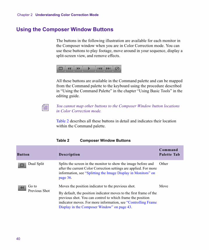
Using the Composer Window Buttons
The buttons in the following illustration are available for each monitor in the Composer window when you are in Color Correction mode. You can use these buttons to play footage, move around in your sequence, display a split-screen view, and remove effects.
All these buttons are available in the Command palette and can be mapped from the Command palette to the keyboard using the procedure described in “Using the Command Palette” in the chapter “Using Basic Tools” in the editing guide.
n You cannot map other buttons to the Composer Window button locations in Color Correction mode.
Table 2 describes all these buttons in detail and indicates their location within the Command palette.
Table 2 Composer Window Buttons
Button DescriptionCommand Palette Tab
Dual Split Splits the screen in the monitor to show the image before and after the current Color Correction settings are applied. For more information, see “Splitting the Image Display in Monitors” on page 36.
Other
Go to Previous Shot
Moves the position indicator to the previous shot.
By default, the position indicator moves to the first frame of the previous shot. You can control to which frame the position indicator moves. For more information, see “Controlling Frame Display in the Composer Window” on page 43.
Move

The Composer Window in Color Correction Mode
41
Go to Next Shot Moves the position indicator to the next shot.
By default, the position indicator moves to the first frame of the next shot. You can control to which frame the position indicator moves. For more information, see “Controlling Frame Display in the Composer Window” on page 43.
Move
Play Plays the material in the monitor from the current position of the position indicator to the end of the segment. If Sequence is selected in the Source menu, clicking this button plays the material from the current position of the position indicator to the end of the sequence. Clicking the button again stops play.
Play
Go to Previous Uncorrected Shot
Moves the position indicator to the last segment before the current segment that has not been color corrected.
By default, the position indicator moves to the first frame of the previous uncorrected shot. You can control to which frame the position indicator moves. For more information, see “Controlling Frame Display in the Composer Window” on page 43.
CC
Go to Next Uncorrected Shot
Moves the position bar to the first segment after the current segment that has not been color corrected.
By default, the position indicator moves to the first frame of the next uncorrected shot. You can control to which frame the position indicator moves. For more information, see “Controlling Frame Display in the Composer Window” on page 43.
CC
Remove Effect Removes the color correction on the current segment for the active side (Source or Program). If the correction has a relationship beyond the single segment, such as Source Tape or Program Track, clicking the Remove Effect button removes the correction on all the segments in the sequence to which it applies.
FX
Table 2 Composer Window Buttons (Continued)
Button DescriptionCommand Palette Tab

Chapter 2 Understanding Color Correction Mode
42
Using the Play Loop Button in Color Correction Mode
The Play Loop button has a specialized function in Color Correction mode. The Play Loop button does not appear in the Composer window but does control the playback of material in the Composer window. You can access the Play Loop button from the Play tab of the Command palette or from the keyboard if it has been mapped to a keyboard location.
When you click the Play Loop button, your Symphony system plays the whole sequence in the active monitor, starting from the current position of the position indicator. Playback is not limited to the current segment alone, regardless of the Source menu option selected for the monitor. This is useful whenever you want to view the whole sequence quickly without switching monitors or making a new Source menu selection.
Reviewing Color-Corrected Clips with the Edit Review Button
The Edit Review button has a specialized function in Color Correction mode. Symphony plays the current clip along with parts of the previous and next clips, allowing you to quickly review the color correction on a clip in the context of the adjoining clips.
The Edit Review button does not appear in the Composer window in Color Correction mode, but you can access the Edit Review button from the Play tab of the Command palette or from the keyboard if it has been mapped to a keyboard location.
When you click the Edit Review button, your Symphony system plays part of the previous clip, all of the current clip, and part of the next clip. When playback is complete, the position indicator returns to its location in the current clip before you clicked the button.
The amount of material the system plays from the previous and next clips is determined by the current Preroll and Postroll settings in the Play Loop tab of the Trim Settings dialog box. For more information on Trim Settings, see “Trim Settings Options” in the chapter “Working in Trim Mode” in the editing guide.

The Composer Window in Color Correction Mode
43
Controlling Frame Display in the Composer Window
You control the behavior of the Go to buttons in the Composer window (Go to Previous Shot, Go to Next Shot, Go to Previous Uncorrected Shot, and Go to Next Uncorrected Shot) by selecting options in the Fast Forward and Rewind area of the Composer Settings dialog box.
You can set your Symphony system to jump to the first frame of the relevant segment (the default setting), the last frame, or the frame that is marked with a locator. For more information on these settings, see “Fast Forward and Rewind Options” in the chapter “Viewing and Marking Footage” in the editing guide.
Although the default first-frame behavior might be acceptable in many circumstances, the availability of the option Stop at Locators makes it possible to mark a reference frame for each segment in your sequence before you begin color correction. As you move around in your sequence, you will always see the reference frame in the monitors.
To control frame display with locators:
1. In Source/Record mode, add a locator to your chosen reference frame for each segment of the sequence using the standard procedure described in “Using Locators” in the chapter “Viewing and Marking Footage” in the editing guide.
n To navigate successfully in the sequence while in Color Correction mode, you must place a locator in every segment. You should not have more than one locator in any segment.
2. In the Settings scroll list of the Project window, double-click Composer.
The Composer Settings dialog box opens.
3. In the Fast Forward (>>) and Rewind (<<) area, select Stop at Locators, and then click OK.

Chapter 2 Understanding Color Correction Mode
44
4. Enter Color Correction mode by clicking the Color Correction Mode button at the bottom of the Timeline.
As you use the Composer Window buttons to move around in your sequence, the Composer window will change to display the frame marked by the locator in each segment.
n You can add locators while in Color Correction mode by mapping the Add Locator button to the keyboard or by using the Command palette in Active mode. However, you cannot change Composer settings while in Color Correction mode.
The Client Monitor in Color Correction Mode
The Client monitor is an important tool for color correction since it allows you to see your corrections as they will appear when output and displayed on a television screen. Your Symphony system’s Edit monitor does not have exactly the same color and luminance display characteristics as a television monitor.
When you are in Color Correction mode, the Client monitor displays the image that is in the currently active monitor in the Composer window. By switching from one monitor to another in the Composer window, you can quickly compare whichever three images are currently displayed in the monitors. For more information on switching between monitors, see “Activating Monitors” on page 32.
When you select Dual Split for the active monitor, the split-screen display also appears in the Client monitor. This allows you to compare uncorrected and corrected versions of the same segment within the Client monitor. If you select Dual Split with Reference from the Color Correction shortcut menu, the split-screen display allows you to compare a shot with the current reference shot within the Client monitor. For more information on using dual-split options, see “Splitting the Image Display in Monitors” on page 36.
The Color Correction Tool
45
n If the Dual Split display does not appear in the Client monitor, make sure that Show Graphics on Client Display is selected in the Interface Settings dialog box. See “Interface Settings” in the chapter “Working with the Project Window” in the editing guide.
The Color Correction Tool
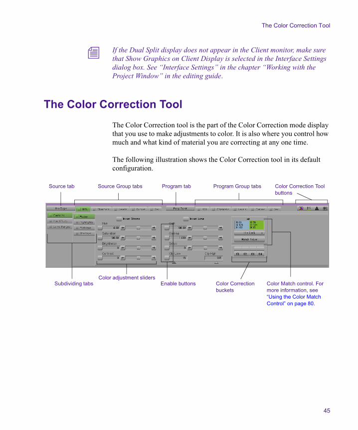
The Color Correction tool is the part of the Color Correction mode display that you use to make adjustments to color. It is also where you control how much and what kind of material you are correcting at any one time.
The following illustration shows the Color Correction tool in its default configuration.
Source tab Program tabSource Group tabs Color Correction Tool buttons
Subdividing tabs Enable buttons Color Match control. For more information, see “Using the Color Match Control” on page 80.
Color Correction buckets
Color adjustment sliders
Program Group tabs
Chapter 2 Understanding Color Correction Mode
46
Understanding the Color Correction Tool Tabs
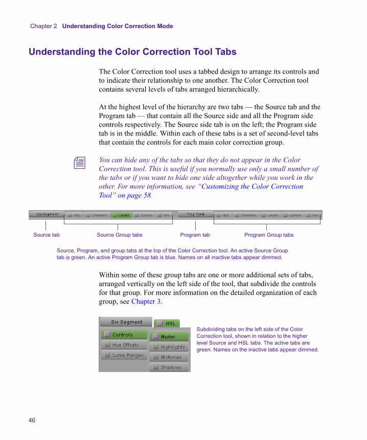
The Color Correction tool uses a tabbed design to arrange its controls and to indicate their relationship to one another. The Color Correction tool contains several levels of tabs arranged hierarchically.
At the highest level of the hierarchy are two tabs — the Source tab and the Program tab — that contain all the Source side and all the Program side controls respectively. The Source side tab is on the left; the Program side tab is in the middle. Within each of these tabs is a set of second-level tabs that contain the controls for each main color correction group.
n You can hide any of the tabs so that they do not appear in the Color Correction tool. This is useful if you normally use only a small number of the tabs or if you want to hide one side altogether while you work in the other. For more information, see “Customizing the Color Correction Tool” on page 58.
Within some of these group tabs are one or more additional sets of tabs, arranged vertically on the left side of the tool, that subdivide the controls for that group. For more information on the detailed organization of each group, see Chapter 3.
Source, Program, and group tabs at the top of the Color Correction tool. An active Source Group tab is green. An active Program Group tab is blue. Names on all inactive tabs appear dimmed.
Source tab Program tabSource Group tabs Program Group tabs
Subdividing tabs on the left side of the Color Correction tool, shown in relation to the higher level Source and HSL tabs. The active tabs are green. Names on the inactive tabs appear dimmed.

The Color Correction Tool
47
The complete hierarchical structure of the Color Correction tool is as follows:
Working with the Source and Program Tabs
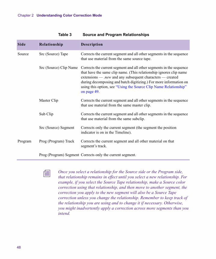
The Source and Program tabs allow you to see which controls apply to either the Source side or the Program side. They also allow you to define the scope of the corrections you make by setting Source or Program relationships. For more information on Source and Program color correction and on Source and Program relationships, see “Understanding Source and Program Color Correction” on page 23 and “Understanding Color Correction Relationships” on page 24.
To change the Source or Program relationships:
t With the pointer over the Source or Program tab, press and hold the mouse button, and then select a relationship.
Table 3 describes the relationship options.
Source or Program tab
Group tab — for example, HSL
Group subdividing tab — for example, Controls within HSL (The HSL group has a second level of subdividing tabs — for example, Highlights within Controls.)
Individual control — for example, Brightness slider within the Highlights pane of the Controls subdividing tab within the HSL group.
Chapter 2 Understanding Color Correction Mode
48
n Once you select a relationship for the Source side or the Program side, that relationship remains in effect until you select a new relationship. For example, if you select the Source Tape relationship, make a Source color correction using that relationship, and then move to another segment, the correction you apply to the new segment will also be a Source Tape correction unless you change the relationship. Remember to keep track of the relationship you are using and to change it if necessary. Otherwise, you might inadvertently apply a correction across more segments than you intend.
Table 3 Source and Program Relationships
Side Relationship Description
Source Src (Source) Tape Corrects the current segment and all other segments in the sequence that use material from the same source tape.
Src (Source) Clip Name Corrects the current segment and all other segments in the sequence that have the same clip name. (This relationship ignores clip name extensions — .new and any subsequent characters — created during decomposing and batch digitizing.) For more information on using this option, see “Using the Source Clip Name Relationship” on page 49.
Master Clip Corrects the current segment and all other segments in the sequence that use material from the same master clip.
Sub Clip Corrects the current segment and all other segments in the sequence that use material from the same subclip.
Src (Source) Segment Corrects only the current segment (the segment the position indicator is on in the Timeline).
Program Prog (Program) Track Corrects the current segment and all other material on that segment’s track.
Prog (Program) Segment Corrects only the current segment.

The Color Correction Tool
49
n You can also apply a Source Segment or a Program Segment correction to the material between marked IN and OUT points. For more information, see “Customizing the Color Correction Tool” on page 58.
n You select which side you are working in (Source or Program) by selecting a group from either the Source side or the Program side. For example, if you have been working in the Source side and then select a group from the Program side, your adjustments in that group will be applied as Program color corrections. At any time, the relationship name for the active side is highlighted in the Source or Program tab, and the relationship name for the inactive side appears dimmed in the other tab.
Using the Source Clip Name Relationship
For many project situations, the Source Tape, Master Clip, and Sub Clip relationships are sufficient to allow you to make any Source color corrections to groups of related clips. When a sequence is moved to a Symphony system from another system or editing facility, however, a common workflow involves decomposing the sequence and redigitizing. This destroys the original clip relationships by creating a new master clip (with a .new.xx extension) for every segment in the sequence.
The Src (Source) Clip Name relationship is designed to allow you to make related corrections after decomposing and redigitizing by referencing the clip name. It applies a correction to the current segment and to any other segment that has the same clip name. The Source Clip Name relationship ignores the clip name extensions that are created during the decomposing and redigitizing cycle.
As long as the clip names are consistent, this relationship effectively allows you to color correct by the original master clip relationship even though that relationship is not directly available to your Symphony system. If you use the Source Clip Name relationship in this way, you should check the clip names before color correcting and verify that they are consistent. If you find names that are in conflict, you can rename them so that they will be correctly referenced by the Source Clip Name relationship.
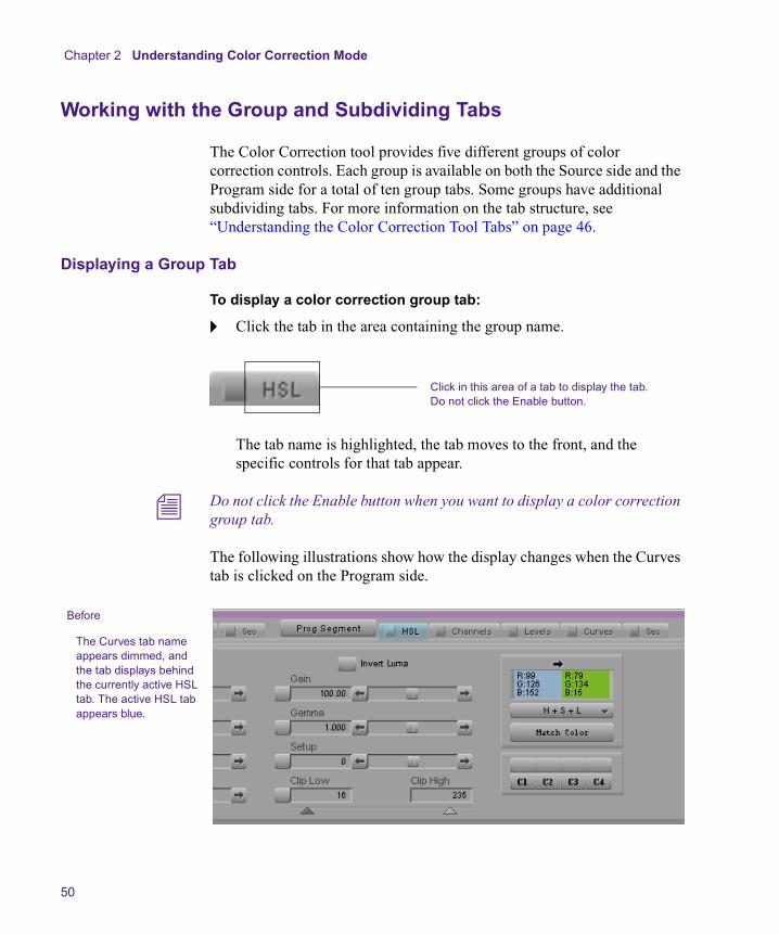
Chapter 2 Understanding Color Correction Mode
50
Working with the Group and Subdividing Tabs
The Color Correction tool provides five different groups of color correction controls. Each group is available on both the Source side and the Program side for a total of ten group tabs. Some groups have additional subdividing tabs. For more information on the tab structure, see “Understanding the Color Correction Tool Tabs” on page 46.
Displaying a Group Tab
To display a color correction group tab:
t Click the tab in the area containing the group name.
The tab name is highlighted, the tab moves to the front, and the specific controls for that tab appear.
n Do not click the Enable button when you want to display a color correction group tab.
The following illustrations show how the display changes when the Curves tab is clicked on the Program side.
Click in this area of a tab to display the tab. Do not click the Enable button.
The Curves tab name appears dimmed, and the tab displays behind the currently active HSL tab. The active HSL tab appears blue.
Before
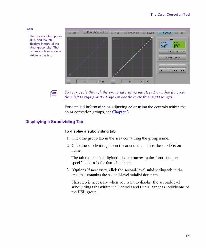
The Color Correction Tool
51
n You can cycle through the group tabs using the Page Down key (to cycle from left to right) or the Page Up key (to cycle from right to left).
For detailed information on adjusting color using the controls within the color correction groups, see Chapter 3.
Displaying a Subdividing Tab
To display a subdividing tab:
1. Click the group tab in the area containing the group name.
2. Click the subdividing tab in the area that contains the subdivision name.
The tab name is highlighted, the tab moves to the front, and the specific controls for that tab appear.
3. (Option) If necessary, click the second-level subdividing tab in the area that contains the second-level subdivision name.
This step is necessary when you want to display the second-level subdividing tabs within the Controls and Luma Ranges subdivisions of the HSL group.
The Curves tab appears blue, and the tab displays in front of the other group tabs. The curves controls are now visible in the tab.
After

Chapter 2 Understanding Color Correction Mode
52
Associating Group and Subdividing Tabs with Tab Buttons
The Command palette contains twelve Tab buttons that you can use to provide one-click access to specific tab displays. For example, if you adjust the Luma Ranges graphs frequently as part of your color correction work, you can configure three tab buttons to display the three Luma Ranges tabs (Highlights, Midtones, and Shadows).
To associate a Color Correction tab with a Tab button:
1. In the Color Correction tool, click the tab that you want to map to a Tab button.
For example, click the Highlights tab within the Luma Ranges tab within the HSL group to assign that specific subdividing tab.
2. Select Tools > Command Palette.
The Command palette opens.
3. Click the CC tab.
The Color Correction buttons appear, including the twelve Tab buttons.
4. At the bottom of the Command palette, select Active Palette.
5. Alt+click (Windows) or Option+click (Macintosh) the Tab button with which you want to associate the Color Correction tab.
Tab buttons

The Color Correction Tool
53
To display a group or subdividing tab using a Tab button:
1. Enter Color Correction mode by clicking the Color Correction Mode button at the bottom of the Timeline.
2. Select Tools > Command Palette.
3. Click the CC tab.
4. Select Active Palette.
5. Click the Tab button with which the group or subdividing tab is associated.
In the Color Correction tool, the tab is highlighted, the tab moves to the front, and the specific controls for the tab appear.
n You can also map the Tab buttons to the keyboard. For more information, see “Using the Command Palette” in the chapter “Using Basic Tools” in the editing guide.
Understanding Interaction Between Color Correction Groups
Understanding how the color correction groups work together is important. Adjustments made in each group are applied cumulatively to the current segment and its related material. If you make an adjustment in one group and then go on to make another adjustment in a different group, the image will show the cumulative effect of both adjustments.
This behavior provides you with a great deal of flexibility. For example, you can use one group of controls to make relatively broad initial adjustments and then switch to another group to fine-tune your correction. If you are unhappy with some of your finer adjustments, you can disable that group or reset its controls to default settings without disrupting the initial group.

Chapter 2 Understanding Color Correction Mode
54
The following illustration shows an example of this kind of control over color correction groups.
In effect, you have up to five layers of correction available on either the Source or the Program side. For more information on enabling, disabling, and resetting the groups, see “Working with the Enable Buttons” on page 55.
n If you make adjustments in multiple groups, keep in mind how the cumulative adjustments will affect the final image. Adjustments might accumulate, or cancel each other out, in ways that you do not want. Keep each stage of your correction distinct, and do not duplicate the same adjustment in more than one group.
The Green and Blue curves are adjusted, but the Curves tab is turned off. The Curves tab adjustments are not currently applied to the segment. Adjustments made in the HSL tab are applied to the segment because the HSL tab is turned on, even though the HSL controls are not currently visible.
Enable button for Curves tab is turned off.
Enable button for HSL tab is turned on.
The Color Correction Tool
55
Working with the Enable Buttons
Each group tab in the Color Correction tool, each subdividing tab and individual control within each group, and each color vector within the Secondary groups has an Enable button. These buttons provide an immediate visual guide to the status of the controls while you are making corrections. They also allow you to turn controls on and off in various combinations and quickly reset controls to their default values.
Turning Controls On or Off
To turn on a control or tabbed group of controls, do one of the following:
t Click the Enable button for the control or tabbed group of controls.
t Adjust any individual control that is linked to the Enable button.
The Enable button changes to pink, and the control or tabbed group of controls becomes active. The system includes the adjustments in that control or group of controls when calculating the corrected color.
To turn off a control or tab:
t Click the Enable button for the control or tab.
The Enable button changes to gray.
Resetting Controls
To reset a control or a tabbed group of controls to its default values:
1. Display the control or group of controls you want to reset.
2. Alt+click (Windows) or Option+click (Macintosh) the Enable button for that control or group of controls.
The Enable button changes to gray, and all controls linked to that button return to their default values.
n You cannot reset controls not currently displayed. If you Alt+click (Windows) or Option+click (Macintosh) the Enable button for a tab whose controls are not currently displayed, you display the controls but do not reset them. Alt+click (Windows) or Option+click (Macintosh) the button again to reset the controls.
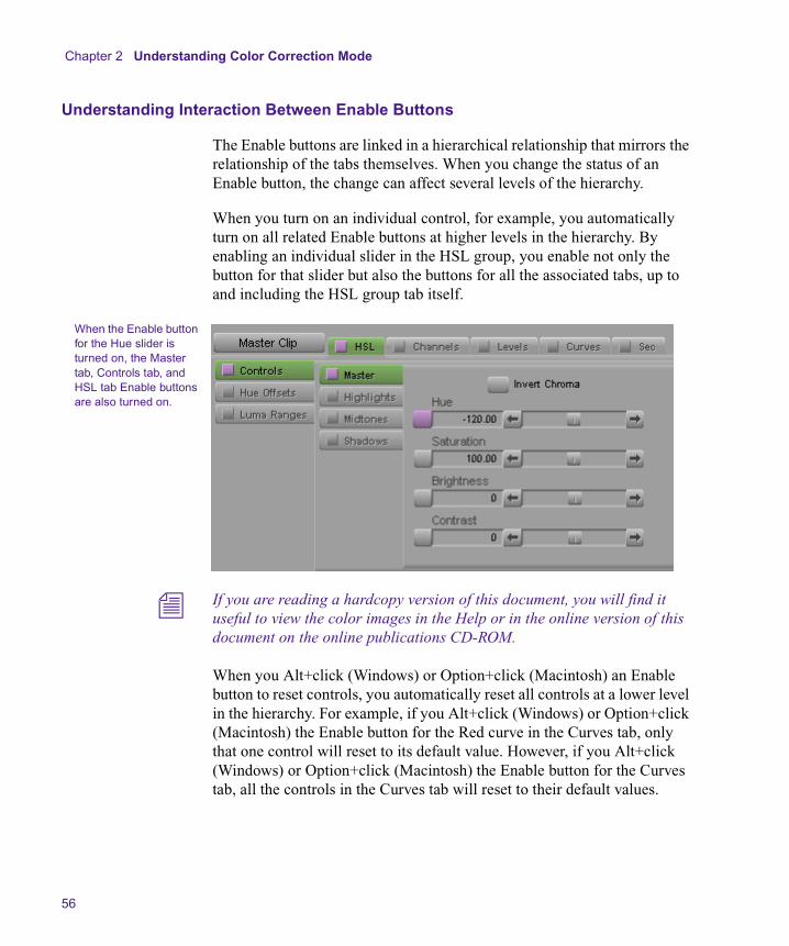
Chapter 2 Understanding Color Correction Mode
56
Understanding Interaction Between Enable Buttons
The Enable buttons are linked in a hierarchical relationship that mirrors the relationship of the tabs themselves. When you change the status of an Enable button, the change can affect several levels of the hierarchy.
When you turn on an individual control, for example, you automatically turn on all related Enable buttons at higher levels in the hierarchy. By enabling an individual slider in the HSL group, you enable not only the button for that slider but also the buttons for all the associated tabs, up to and including the HSL group tab itself.
n If you are reading a hardcopy version of this document, you will find it useful to view the color images in the Help or in the online version of this document on the online publications CD-ROM.
When you Alt+click (Windows) or Option+click (Macintosh) an Enable button to reset controls, you automatically reset all controls at a lower level in the hierarchy. For example, if you Alt+click (Windows) or Option+click (Macintosh) the Enable button for the Red curve in the Curves tab, only that one control will reset to its default value. However, if you Alt+click (Windows) or Option+click (Macintosh) the Enable button for the Curves tab, all the controls in the Curves tab will reset to their default values.
When the Enable button for the Hue slider is turned on, the Master tab, Controls tab, and HSL tab Enable buttons are also turned on.
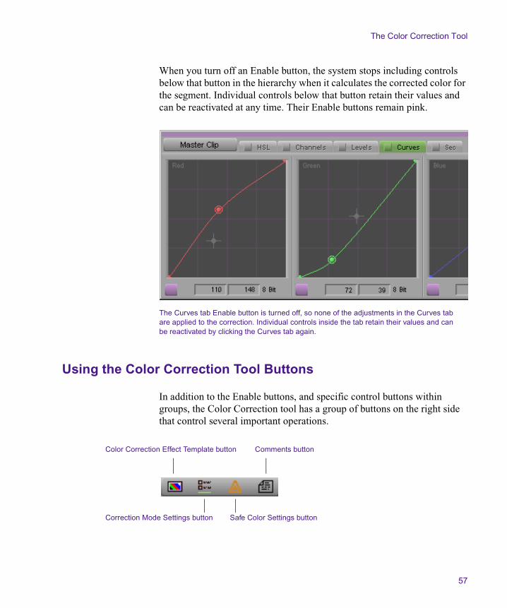
The Color Correction Tool
57
When you turn off an Enable button, the system stops including controls below that button in the hierarchy when it calculates the corrected color for the segment. Individual controls below that button retain their values and can be reactivated at any time. Their Enable buttons remain pink.
Using the Color Correction Tool Buttons
In addition to the Enable buttons, and specific control buttons within groups, the Color Correction tool has a group of buttons on the right side that control several important operations.
The Curves tab Enable button is turned off, so none of the adjustments in the Curves tab are applied to the correction. Individual controls inside the tab retain their values and can be reactivated by clicking the Curves tab again.
Safe Color Settings button
Comments buttonColor Correction Effect Template button
Correction Mode Settings button

Chapter 2 Understanding Color Correction Mode
58
Use these buttons to:
• Create Color Correction effect templates.
For more information, see “Working with Color Correction Effect Templates” on page 66.
• Customize the Color Correction tool.
For more information, see “Customizing the Color Correction Tool” on page 58.
• Set Safe Color limits.
For more information, see Chapter 7.
• Add comments to color-corrected segments.
For more information, see “Adding Comments to Color Correction Effects” on page 64.
Customizing the Color Correction Tool
You can customize the appearance and behavior of the Color Correction tool in a variety of ways by selecting options in the Correction Mode Settings dialog box. For example, you can control which of the group tabs display, allowing you to remove from the tool any group that you do not normally use.
To customize the Color Correction tool:
1. Do one of the following:
t In the Color Correction tool, click the Correction Mode Settings button.
t In the Project window, click the Settings tab, and then double-click Correction in the Settings scroll list.
The Correction Mode Settings dialog box opens.
Table 4 on page 59 describes the options available in the Correction Mode Settings dialog box.
The Color Correction Tool
59
2. Click one of the tabs, and then select the options you want.
3. Repeat step 2 until you are satisfied with all settings.
4. Click OK.
Table 4 Correction Mode Settings Options
Tab Option Description
Tabs Source:
• HSL
• Channels
• Levels
• Curves
• Secondary
Define which group tabs appear in the Source tab of the Color Correction tool. Select the groups that you want to display in the Source tab.
Program:
• HSL
• Channels
• Levels
• Curves
• Secondary
Define which group tabs appear in the Program tab of the Color Correction tool. Select the groups that you want to display in the Program tab.
n You might want to disable all the groups for the Program side while you are working on Source color corrections and disable all the groups for the Source side while you are working on Program color corrections. This ensures that you do not accidentally switch from one side to the other.

Chapter 2 Understanding Color Correction Mode
60
Units RGB:
• 10 Bit
• 8 Bit
• Percent
• IRE
• mVolts
Hue:
• 8 Bit
• Degree
Saturation/Gain:
• 8 Bit
• Percent
Luma:
• 8 Bit
• Percent
• IRE
• mVolts
Composite:
• IRE
• mVolts
For each type of color adjustment, select an item from the pop-up menu to define the unit of measurement used for that adjustment type in the Color Correction tool. The following units of measurement are available in one or more of the pop-up menus:
10 Bit — Measures the adjustment on a scale from 0 to 1024. This provides more precise corrections for those adjustments that have the 10-bit option. For more information, see “Understanding 10-bit Units” on page 64.
8 Bit — Measures the adjustment on a scale from 0 to 255.
n The RGB value for a color in the Color Correction tool will not be identical to the RGB value for the same color in a graphics application such as Adobe Photoshop®. For example, the 10-bit RGB values for reference black and reference white are 288 and 726 respectively. The 8-bit RGB values for reference black and reference white are 16 and 235 respectively.
Percent — Measures the adjustment on a percentage scale from 0 to 100.
IRE — Measures the adjustment in IRE units.
mVolts — Measures the adjustment in millivolts.
Degree — Measures the adjustment on a scale of degrees that represent a position on the color wheel. 0/360 represents the existing hue; 180 represents the opposite hue on the wheel (inverts the hue).
Table 4 Correction Mode Settings Options (Continued)
Tab Option Description

The Color Correction Tool
61
Levels Solid Histograms When this option is selected, the histograms in the Levels tab of the Color Correction tool display as solid forms. When this option is deselected, the histograms display as a line graph.
Color Histograms When this option is selected, histograms that represent a single color channel display in the color of that channel. For example, histograms in the Red tab will display in red.
Dynamic Histograms When this option is selected, the histograms update on-the-fly as you move other controls such as triangular sliders and control points on the Curve graph. This provides instant feedback on your adjustments, but the updating process might not always be smooth due to system processing limitations.
When this option is deselected, the histograms do not update until you release the controls you are adjusting.
Table 4 Correction Mode Settings Options (Continued)
Tab Option Description
Solid histogram deselectedSolid histogram selected
Chapter 2 Understanding Color Correction Mode
62
Use Full Ranges When this option is selected, some histograms redraw to display the full 10-bit range of level values on the horizontal axis. The option applies to the Red, Green, Blue, and Master histograms. You then have additional headroom and footroom available for making adjustments beyond the normal range of values.
This is sometimes useful when dealing with extreme color deficiencies in analog video material, such as very low RGB levels. It is not usually necessary to use full ranges with digital material since digital video has built-in headroom and footroom limits.
Features Secondary Vectors:
• Show All
• Show Standard
• Show Custom
• Show Enabled
Controls which color vectors appear on the input vector color wheel in the Secondary group. For more information and illustrations of these options, see “Customizing a Vector Display” on page 157.
Saved Color Labels:
• None
• RGB
• Name
• Name and RGB
Select an item from the pop-up menu to control how custom colors are named in bins. For information on saving custom colors, see “Saving Custom Colors to a Bin” on page 90.
When None is selected, the system does not supply a name.
When RGB is selected, the system uses the 8-bit values for the red, green, and blue components as the name.
When Name is selected, the system uses the name from the standard HTML color scheme that most closely matches the color you are saving.
When Name and RGB is selected, the system uses both the Name and the RGB information as the name. This is the default option.
Use Marks for Segment Correction
When this option is selected, the system will apply either Source Segment or Program Segment color correction to all segments between marked IN and OUT points. If the IN and OUT points are in the middle of segments, the system includes the whole segments when it makes the correction.
This option is deselected by default.
Table 4 Correction Mode Settings Options (Continued)
Tab Option Description

The Color Correction Tool
63
Real-time Image Updating
When this option is selected, the image in the active monitor updates on-the-fly as you move controls in the Color Correction tool. This provides instant feedback on your adjustments, but the updating process might not always be smooth due to system processing limitations. This is the default option.
When this option is deselected, the histograms do not update until you release the controls you are adjusting.
n You can switch the current setting for Real-Time Image Updating on and off by pressing and holding the Alt key (Windows) or Option key (Macintosh). If Real-Time Image Updating is on, pressing and holding the Alt key (Windows) or Option key (Macintosh) will turn updating off temporarily. If Real-Time Image Updating is off, pressing and holding the Alt key (Windows) or Option key (Macintosh) will turn updating on temporarily.
Eyedropper 3 x 3 Averaging
When this option is selected, the system calculates the color value to pick by averaging the values of a 3 x 3 sample of pixels centered on the eyedropper’s position. This is often useful for picking up a color accurately by sight because it compensates for shifts in color value from one pixel to another. When this option is deselected, the system selects the color value of the exact pixel at the eyedropper’s position.
Show Eyedropper Info When this option is selected, the numerical RGB values appear on the color swatches in the Color Match controls.
Show Color Wheels When this option is selected, the system displays the color wheels in full color in the Hue Offsets tab of the HSL group and in the Secondary group tab.
When this option is deselected, the system displays outline color wheels that resemble the Vectorscope monitor in the Video Input tool. This is the default option. You might prefer to use this option when you are working since it allows you to assess color in your video images without interference from other brightly colored on-screen elements.
Table 4 Correction Mode Settings Options (Continued)
Tab Option Description

Chapter 2 Understanding Color Correction Mode
64
Understanding 10-bit Units
When your Symphony system makes color correction adjustments, it converts the color information in the media stored on disk into a better format for color correction and then converts the information back to the original format for playback and storage. This round-trip conversion takes the color information from an 8-bit YCrCb color space into a 10-bit RGB color space and then back to 8-bit YCrCb. The 10-bit RGB color space that the system uses is designed to preserve color information as fully as possible during this process. Clipping of the original color values is virtually eliminated, and round-off errors from the two conversions are minimized.
The options for measuring units available in the Correction Mode Settings dialog box are a convenience that allows you to make adjustments using the units that are most useful or familiar to you. When the system makes the color correction adjustments, it always uses the 10-bit RGB color space and always works with the same degree of accuracy.
The 10-bit Units option for RGB values allows you to make color correction adjustments using units that correspond exactly to those the system hardware uses. Some users might find this a valuable option, while others will prefer working with units that have more general currency in the video industry.
Adding Comments to Color Correction Effects
You can add comments to color-corrected segments to assist you in your work. For example, you might want to briefly note the type of adjustment you made to a segment or to make notes during a Source correction pass of ideas for adjustments to be done later during a Program pass. You can display these comments in the Timeline as well as in the Comments dialog box.
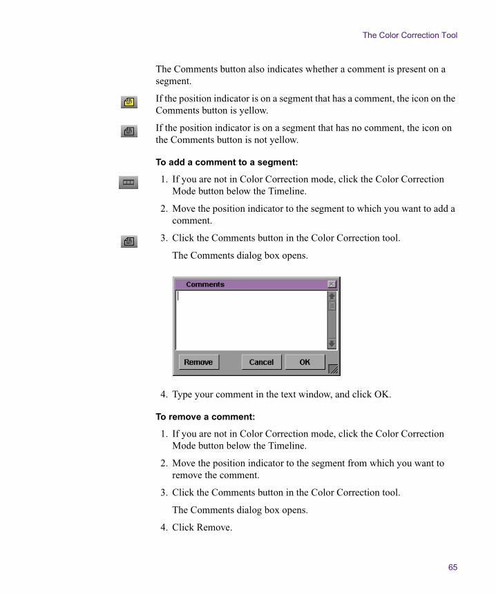
The Color Correction Tool
65
The Comments button also indicates whether a comment is present on a segment.
If the position indicator is on a segment that has a comment, the icon on the Comments button is yellow.
If the position indicator is on a segment that has no comment, the icon on the Comments button is not yellow.
To add a comment to a segment:
1. If you are not in Color Correction mode, click the Color Correction Mode button below the Timeline.
2. Move the position indicator to the segment to which you want to add a comment.
3. Click the Comments button in the Color Correction tool.
The Comments dialog box opens.
4. Type your comment in the text window, and click OK.
To remove a comment:
1. If you are not in Color Correction mode, click the Color Correction Mode button below the Timeline.
2. Move the position indicator to the segment from which you want to remove the comment.
3. Click the Comments button in the Color Correction tool.
The Comments dialog box opens.
4. Click Remove.

Chapter 2 Understanding Color Correction Mode
66
To view or edit a comment in the Comments dialog box:
1. In Color Correction mode, move the position indicator to the segment for which you want to view the comment.
2. Click the Comments button in the Color Correction tool.
The Comments dialog box opens and displays the text of the comment.
3. (Option) To edit the comment, click in the text window and make your edits using standard word processing procedures.
To display comments in the Timeline:
t Click the Timeline Fast Menu button, and select Clip Text > Comments.
Your Color Correction comments appear in the Timeline.
Working with Color Correction Effect Templates
Color Correction mode offers several versions of Color Correction effect templates.
• The Automatic Effect Templates feature saves recent corrections automatically and lists them in the Effect Palette.
• The Color Correction buckets provide an easily accessible location within the Color Correction tool for the short-term storage of Color Correction effect templates.
• The Color Correction Effect Template button allows you to create a template for any color correction and save it to a bin in the same way that you save other kinds of Symphony effect templates. The Save Correction button in the CC tab of the Command palette performs the same function.
Working with Color Correction Effect Templates
67
Like templates for other effects, Color Correction effect templates save all the adjustment values for a color correction so that you can apply those values quickly to another segment. You can apply all the values at once by clicking the template icon in the bin or in the Effect Palette, and dragging it into the monitor containing the current segment, or you can apply the values for the controls in a single tab in the Color Correction tool by clicking the template icon and dragging it to the tab that contains the group of controls you want to change.
n You can also save custom colors to bins. For more information, see “Using the Color Match Control” on page 80.
Understanding How Color Correction Effect Templates Save Settings
When you create a Color Correction effect template, the system saves all the Color Correction settings for the segment. This is true whether the template is created automatically by the system or manually by saving to a bin or a bucket. The system remembers both the values set for each control and the status of each Enable button.
Automatic templates update when you make new adjustments on the same segment. For example, when you have made only a single adjustment, the template contains the value of that adjustment. If you make another Source side adjustment to the same clip, the template updates to include the value of the new adjustment. In contrast, templates saved to a bin or a bucket do not update when you make new adjustments to the segment. To save the new adjustments you must save a new template to a bin or a bucket.
If you make adjustments on both the Source and the Program side, the template includes all those adjustments. When you apply the template globally by dragging it into the active monitor, you apply both Source and Program side Color Correction settings if the template includes both.
Chapter 2 Understanding Color Correction Mode
68
Since this behavior might lead to confusing results, it reinforces the need in most circumstances to keep Source and Program color corrections completely separate. In general, you should use the Program side only for final adjustments, which will often be made across a whole track. For more information on keeping Source and Program sides separate, see the note at the end of “General Workflow for Making Color Corrections” on page 78.
n Remember that you can specify which settings you apply in a template by dragging the template to the active tab in the Color Correction tool. This changes only those settings contained within that tab. Using this method, you can, for example, apply Source settings one tab at a time without applying any Program settings that might also be saved in a template.
n If you make a Source color correction on a clip and then switch to the Program side to make another correction, the system saves a second template in the Effect Palette list. This second template is a duplicate. The two templates are identical in the information they contain — each contains both the Source and the Program information — and applying either to a new segment will apply all the saved information.
Using Automatic Effect Templates
Your Symphony system saves the most recent color corrections made in a sequence (up to a limit of 16 corrections) and makes them available in the Effect Palette. This provides you with automatically created templates for all your most recent corrections. You can quickly apply any one of these templates to another segment in the sequence by dragging it or simply by highlighting it in the Effect Palette and pressing Enter (Windows) or Return (Macintosh).
The Effect Palette lists all color-corrected sequences that are loaded in the Record monitor at the bottom of the scrollable list of effect categories. The effect categories list might therefore contain effect categories, bins that contain saved effects, and color-corrected sequences.
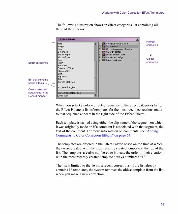
Working with Color Correction Effect Templates
69
The following illustration shows an effect categories list containing all three of these items.
When you select a color-corrected sequence in the effect categories list of the Effect Palette, a list of templates for the most recent corrections made to that sequence appears in the right side of the Effect Palette.
Each template is named using either the clip name of the segment on which it was originally made or, if a comment is associated with that segment, the text of the comment. For more information on comments, see “Adding Comments to Color Correction Effects” on page 64.
The templates are ordered in the Effect Palette based on the time at which they were created, with the most recently created template at the top of the list. The templates are also numbered to indicate the order of their creation, with the most recently created template always numbered “1.”
The list is limited to the 16 most recent corrections. If the list already contains 16 templates, the system removes the oldest template from the list when you make a new correction.
Effect categories
Bin that contains saved effects
Color-corrected sequences in the Record monitor
Newest correction
Oldest correction

Chapter 2 Understanding Color Correction Mode
70
Saving a Color Correction Effect Template to a Bin
You can save a color correction template to a bin using either the Color Correction Effect Template button in the Color Correction tool or the Save Correction button in the CC tab of the Command palette.
Color correction templates saved to a bin are saved permanently, unlike templates saved to a bucket, which are not saved beyond the current working session, and automatic templates, which are deleted when you have made 16 more recent corrections.
To save a Color Correction effect template to a bin:
For help, see “Entering and Exiting Color Correction Mode” on page 30.
1. In Color Correction mode, make sure that the position indicator is in the segment that contains the settings you want to save.
2. Do one of the following:
t Click the Color Correction Effect Template button, and drag the effect icon to a bin.
t With Active Palette selected in the Command palette, click the Save Correction button in the CC tab.
t If the Save Correction button is mapped to a key, press that key.
Effect icons for open bins are also displayed in the Effect Palette.
A new effect template appears in the bin, containing all the color correction adjustment values for the segment. The new effect template is identified in the bin by its effect icon. By default, the system names the template using the clip name of the segment.
3. (Option) To rename the template, click the template name and type a new name.

Working with Color Correction Effect Templates
71
Saving a Color Correction Effect Template to a Bucket
The Color Correction tool provides four buckets, located below the Color Match control, that you can use to save Color Correction effect templates for the duration of a working session. You can then apply the template quickly to any segment. The buckets are labeled C1 through C4.
n You can map any of the Color Correction buckets from the CC tab in the Command palette to the keyboard, for example, to a function key, using the standard procedures for mapping buttons described in the chapter “Using Basic Tools” in the editing guide.
The following illustration shows the Color Correction buckets.
To save a Color Correction effect template in a bucket:
For help, see “Entering and Exiting Color Correction Mode” on page 30.
1. In Color Correction mode, make sure that the position indicator is in the segment that contains the adjustment values you want to save.
2. Alt+click (Windows) or Option+click (Macintosh) the bucket in which you want to save the template.
3. Select a bucket from the range C1 to C4. Empty buckets have a blank icon holder above them. If you Alt+click (Windows) or Option+click (Macintosh) a bucket that already contains a template, you overwrite the previous template with the new adjustment values.
The values are saved as a template, and a Color Correction icon appears in the icon holder above the Color Correction bucket.
n Color Correction effect templates that are saved to buckets do not remain from one session to another. When you quit the Symphony application, the templates are deleted. You can save an effect template in a bucket permanently by clicking the Color Correction icon in the icon holder and dragging it to a bin.
Icon holders
Buckets

Chapter 2 Understanding Color Correction Mode
72
Applying Color Correction Effect Templates
For help, see “Entering and Exiting Color Correction Mode” on page 30.
To apply all adjustment values in a Color Correction effect template to the current segment, do one of the following in Color Correction mode:
t Click the effect icon for the template in the bin, the Effect Palette, or the Color Correction bucket icon holder, and drag it to the monitor containing the current segment.
n For tips on working with templates in the Effect Palette, see “Saving a Color Correction Effect Template to a Bin” on page 70.
t Select the template in the bin or the Effect Palette, and then press Enter (Windows) or Return (Macintosh).
t Click the appropriate Color Correction bucket (for example, C1).
t If you have mapped the Color Correction bucket to the keyboard, press the appropriate key.
The system applies all the Color Correction adjustments in the template to the segment that is the current location of the position indicator.
To apply adjustment values from a Color Correction effect template selectively to a single tab of color correction controls:
1. In the Color Correction tool, click the tab to which you want to apply the template.
2. Click the effect icon for the template in the bin, the Effect Palette, or the Color Correction bucket, drag it to the tab, and drop it anywhere in the tab.
The controls in that tab update to reflect the values in the template. Other color correction controls are not affected.
n If you apply template settings to a subdividing tab (for example, the Controls tab in the HSL group), the image in the monitor does not reflect those settings until you enable the group tab (for example, the HSL tab).

Working with Color Correction Effect Templates
73
n If you apply a saved Color Correction effect template to a segment that already has a color correction, you overwrite the existing correction. The existing Color Correction settings are lost. If the existing correction is itself saved as a template, the template might also be lost (depending on the scope of the existing correction). Make sure that you want to replace the existing correction before you apply a saved Color Correction effect template to a clip that already has a correction. You can use the Undo command to undo the effect of a Color Correction effect template. However, once the Undo command is no longer available, you cannot recover the original Color Correction settings.
Working with Color Correction Effect Templates in the Effect Palette
The following list of reminders and suggestions can help you work quickly when you are using saved Color Correction effect templates in the Effect Palette.
• Press Ctrl+8 (Windows) or k+8 (Macintosh) to open the Effect Palette or to make the Effect Palette active.
The Effect Palette becomes inactive whenever you perform an action in another area of the interface (for example, when you move the position indicator in the Timeline). Pressing Ctrl+8 (Windows) or k+8 (Macintosh) is a quick keyboard method for reactivating the Effect Palette. The Effect Palette must be active before you can use it to apply a Color Correction effect template.
• Use the Tab key to make one side or the other of the Effect Palette active.
For example, if the effect categories list on the left side of the Effect Palette is active, press the Tab key to activate the list of templates on the right side. Press the Tab key again to activate the effect categories list. Clicking a specific item in either list also activates that side of the Effect Palette.
• To display a group of effect templates in the Effect Palette, select the bin or the color-corrected sequence that contains the templates in the effect categories list on the left side of the palette.
Chapter 2 Understanding Color Correction Mode
74
• Use the Up Arrow and Down Arrow keys to move through the active list.
For example, you can quickly move from the most recent correction to the third most recent in the list by pressing the Down Arrow key twice.
• The Effect Palette remembers the currently selected item in the list of corrections even when it becomes inactive or is closed.
For example, if you have the most recent correction in the list selected and then leave the Effect Palette to perform another operation or close the Effect Palette, that correction will be the selected correction when you reactivate or reopen the Effect Palette.
This makes it easy to apply the same template successively to a number of segments, especially if you have navigation buttons such as Fast Forward, Rewind, Go to Next Uncorrected Shot, and Go to Previous Uncorrected Shot mapped to the keyboard. Once you have the template you want selected in the Effect Palette, you simply navigate to another segment, press Ctrl+8 (Windows) or k+8 (Macintosh) to activate the Effect Palette, and then press Enter (Windows) or Return (Macintosh) to apply the template.
Displaying Color Correction Information in the Timeline
The Timeline works the same way in Color Correction mode as it does in other modes. You can move the position indicator from one place to another in your sequence, select and deselect tracks, and perform other normal Timeline operations.
The only control in the Timeline that is specific to color correction is the Color Correction option in the Timeline Fast menu. When you select Color Correction, the Timeline displays indicator lines to show which segments have Source or Program color correction.
A segment that has Source color correction is marked with a green line at the bottom of the segment; a segment that has Program color correction is marked with a blue line at the top of the segment. The appearance of the indicator line indicates the relationship that applies to the correction on
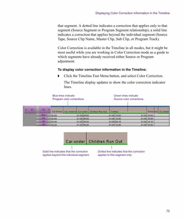
Displaying Color Correction Information in the Timeline
75
that segment. A dotted line indicates a correction that applies only to that segment (Source Segment or Program Segment relationship); a solid line indicates a correction that applies beyond the individual segment (Source Tape, Source Clip Name, Master Clip, Sub Clip, or Program Track).
Color Correction is available in the Timeline in all modes, but it might be most useful while you are working in Color Correction mode as a guide to which segments have already received either Source or Program adjustment.
To display color correction information in the Timeline:
t Click the Timeline Fast Menu button, and select Color Correction.
The Timeline display updates to show the color correction indicator lines.
Green lines indicate Source color corrections.
Blue lines indicate Program color corrections.
Dotted line indicates that the correction applies to this segment only.
Solid line indicates that the correction applies beyond this individual segment.

Chapter 2 Understanding Color Correction Mode
76

Chapter 3
Performing Color Corrections
This chapter describes basic procedures for making color corrections and provides a complete explanation of all the individual controls in the Color Correction tool and how to use them.
• General Workflow for Making Color Corrections
• Using the Color Match Control
• The HSL (Hue, Saturation, Luminance) Group
• The Channels Group
• The Levels Group
• The Curves Group
• The Secondary Group
• Working with the Waveform Monitors and Vectorscope Monitor
• Using the Color Correction Effect in the Effect Palette
Chapter 3 Performing Color Corrections
78
General Workflow for Making Color Corrections
The Color Correction tool gives you a great deal of flexibility when you make color corrections. The exact workflow that you employ will depend on your individual methods, your degree of familiarity with the color correction controls, and the requirements of your project. However, the basic steps to take when making a correction will be similar for all users.
The following procedure outlines a typical color correction operation. You can adapt the exact order in which steps are performed or repeated to conform to your particular needs.
To color correct a sequence:
1. In Source/Record or Finishing mode, load the sequence into a monitor.
2. Click the Color Correction Mode button below the Timeline to enter Color Correction mode.
3. (Option) If necessary, configure the Color Correction mode display so that it conforms to the requirements of your project and editing style. For more information on the display and how to configure it, see Chapter 2.
4. Preview the material in the sequence to develop a sense of the kinds of corrections that are needed and the approach you will use to make them.
For example, you might look for a shot that you would like to use as a reference for your adjustments and lock that shot in one of the monitors. You might also make decisions about the Source or Program relationships that you want to use as you work. For general guidance on what to look for when previewing material, see Chapter 5.
General Workflow for Making Color Corrections
79
n Some users might prefer to preview extensively and plan their corrections in advance. Others, especially those with more color correcting experience, might work by moving back and forth frequently between making corrections and assessing the material on which they are working.
5. Make sure that the Record Track button for the track on which you want to make corrections is the topmost selected button in the Track Selector panel in the Timeline.
You can color correct any number of tracks, including nested tracks by stepping into the nest. However, you can correct only one track at a time. Color correction is applied to the topmost selected track in a sequence.
6. Use the Composer Window buttons or the position indicator in the Timeline to move to a segment you want to correct.
n You cannot apply color corrections to filler material. If you attempt to make color corrections when the position indicator is on filler, the color correction sliders and buttons do not function and a message box opens.
7. Select a relationship to control the scope of the corrections.
Depending on your circumstances, you might use the same relationship throughout the sequence, or you might select different relationships for different segments.
8. Click the appropriate tabs in the Color Correction tool to display the controls you want to use to make the correction.
9. Adjust the controls until you are satisfied with the correction.
Remember that you can repeat steps 7 and 8 to make successive adjustments using several different groups of controls and to selectively turn them on and off while you assess their effect on the segment. You can use the Dual Split button in the monitors to view corrected and uncorrected images side by side.
10. (Option) Add a comment for the correction.
Chapter 3 Performing Color Corrections
80
11. Repeat steps 5 through 10 for each segment you want to correct.
12. When you are satisfied with the corrections throughout the sequence, click one of the mode buttons (Source/Record, Trim, or Effect) or make a selection from the Toolset menu to exit Color Correction mode and return to other editing operations.
n In general, you should not attempt to make Source color corrections and Program color corrections as part of the same corrective operation or to use the Program side for your first color correcting pass. If you do so, you lose flexibility and control for later stages of your project and you reduce the power of the Color Correction tool. Even if you expect to need only one color correction pass (and could use Program relationships for that pass), you should make that pass on the Source side. If your needs for the project change, you will still be able to make a second set of corrections on the Program side.
Using the Color Match Control
Each Color Correction group includes a Color Match control. This control allows you to quickly make a correction by selecting input and output colors from your images, or from the Windows Color dialog box or the Macintosh® Color Picker.
When you use the Color Match control, the system replaces the input color value with the output color value and adjusts all the other color values in the image proportionally. The system also automatically adjusts the other controls in the group to reflect the change. You can set the combination of color channels or components the system uses to determine the match by making menu selections.
For example, if you want to replace the blue sky tone in one image with that in another to match the two shots, you can use the Color Match control to pick the two colors and automate the color adjustment.
When you are working in the Curves group, the Color Match control also includes the NaturalMatch™ feature. NaturalMatch allows you to replace the hue values in an image with new output values without distorting the saturation and luminance values in the image.

Using the Color Match Control
81
You can also Alt+drag (Windows) or Option+drag (Macintosh) colors to a bin and save them as custom colors. You can then drag a custom color into the Color Match control at any time.
The following illustration shows the Color Match control.
n Slightly different versions of the Color Match control also appear as effect parameters in the Spot Color Correction effect and the Paint Effect. For more information on spot color correction, see Chapter 6.
Making a Correction with the Color Match Control
To make a correction using the Color Match control:
1. If you have not already done so, click the Color Correction Mode button below the Timeline to enter Color Correction mode.
2. In the Color Correction tool, click the tab that includes the Color Match control with which you want to work.
For information on the Correction Mode Settings dialog box, see “Customizing the Color Correction Tool” on page 41.
3. (Option) Select Eyedropper 3 x 3 Averaging in the Correction Mode Settings dialog box.
When you select Eyedropper 3 x 3 Averaging, the system calculates the color value to pick by averaging the values of a 3 x 3 sample of pixels centered on the eyedropper’s position. This is often useful for picking up a color accurately by sight because it compensates for shifts in color value from one pixel to another. When this option is deselected, the system selects the color value of the exact pixel at the eyedropper’s position.
4. Select the input color (the color to be replaced):
a. Move the pointer over the input color swatch.
The pointer changes to an eyedropper.
Input color swatch
Output color swatch
Match Type button
Match Color button
Chapter 3 Performing Color Corrections
82
b. Press and hold the mouse button, and then drag the eyedropper to the area of the image in the monitor from which you want to select an input value.
The input color swatch in the Color Match control updates as you move the eyedropper in the image.
c. Release the mouse button to complete the selection.
The input color appears in the input color swatch.
n You can also select an input color from the Windows Color dialog box or the Macintosh Color Picker by double-clicking the input color swatch. However, you will usually want to select your input color from the current segment.
5. Select the output color:
a. Move the pointer over the output color swatch.
The pointer changes to an eyedropper.
b. Press and hold the mouse button, and then drag the eyedropper to the area of the image in the monitor from which you want to select an output value.
The output color swatch in the Color Match control updates as you move the eyedropper in the image.
c. Release the mouse button to complete the selection.
The output color appears in the output color swatch.
n Your output color will usually be selected from an image other than the current segment, such as the next segment or a reference frame. Alternatively, you can double-click the output color swatch and select a color from the Windows Color dialog box or the Macintosh Color Picker. The Windows Color dialog box and the Macintosh Color Picker are useful for selecting an “ideal” replacement color such as a completely neutral gray. You can also use the Windows Color dialog box or the Macintosh Color Picker to create and store custom colors. For more information on using the Windows Color dialog box or the Macintosh Color Picker, see “Using the Windows Color Dialog Box” or “Using the Macintosh Color Picker” in the chapter “Customizing Effects in Effect Mode” in the effects guide.

Using the Color Match Control
83
6. Click the Match Type button, and select a Match Type to determine the exact nature of the match the system makes.
The options available in the Match Type pop-up menu depend on the group in which you are working. For more information on Match Type options, see “Selecting Match Type Options” on page 83.
7. Click the Match Color button to make the correction.
The system adjusts the current segment and resets the group controls to reflect the adjustment. The corrected image displays in the monitor that contains the current segment.
Selecting Match Type Options
The options available in the Match Type pop-up menu reflect the way in which color is handled in the group in which you are working. The following tables describes the options available in the Match Type pop-up menu.
Table 5 describes the Match Type options for the HSL group in the Controls tab.
Table 5 HSL Group (Controls Tab) Match Type Options
Option Description
H + S + L The system matches based on the hue, saturation, and luminance of the color selected in the output color swatch.
Hue The system matches based on only the hue of the color selected in the output color swatch.
Saturation The system matches based on only the saturation of the color selected in the output color swatch.
Luminance The system matches based on only the luminance of the color selected in the output color swatch.

Chapter 3 Performing Color Corrections
84
Table 6 describes the Match Type options for the HSL group in the Hue Offsets tab.
H + S The system matches based on both the hue and the saturation of the color selected in the output color swatch.
H + L The system matches based on both the hue and the luminance of the color selected in the output color swatch.
S + L The system matches based on both the saturation and the luminance of the color selected in the output color swatch.
Table 5 HSL Group (Controls Tab) Match Type Options (Continued)
Option Description
Table 6 HSL Group (Hue Offsets Tab) Match Type Options
Option Description
Master The system matches based on both the hue and the saturation across the full tonal range.
Highlights The system matches based on both the hue and the saturation across the highlights portion of the tonal range as defined in the Luma Ranges tab.
Midtones The system matches based on both the hue and the saturation across the midtones portion of the tonal range as defined in the Luma Ranges tab.
Shadows The system matches based on both the hue and the saturation across the shadows portion of the tonal range as defined in the Luma Ranges tab.

Using the Color Match Control
85
Table 7 describes the Match Type options for the Channels tab.
Table 7 Channels Tab Match Type Options
Option Description
Master The system matches based on the luminance of the color selected in the output color swatch.
R + G + B The system matches based on the values of all three color channels of the color selected in the output color swatch.
Red The system matches based on only the value of the Red color channel of the color selected in the output color swatch.
Green The system matches based on only the value of the Green color channel of the color selected in the output color swatch.
Blue The system matches based on only the value of the Blue color channel of the color selected in the output color swatch.
R + G The system matches based on the values of the Red and Green color channels of the color selected in the output color swatch.
R + B The system matches based on the values of the Red and Blue color channels of the color selected in the output color swatch.
G + B The system matches based on the values of the Green and Blue color channels of the color selected in the output color swatch.
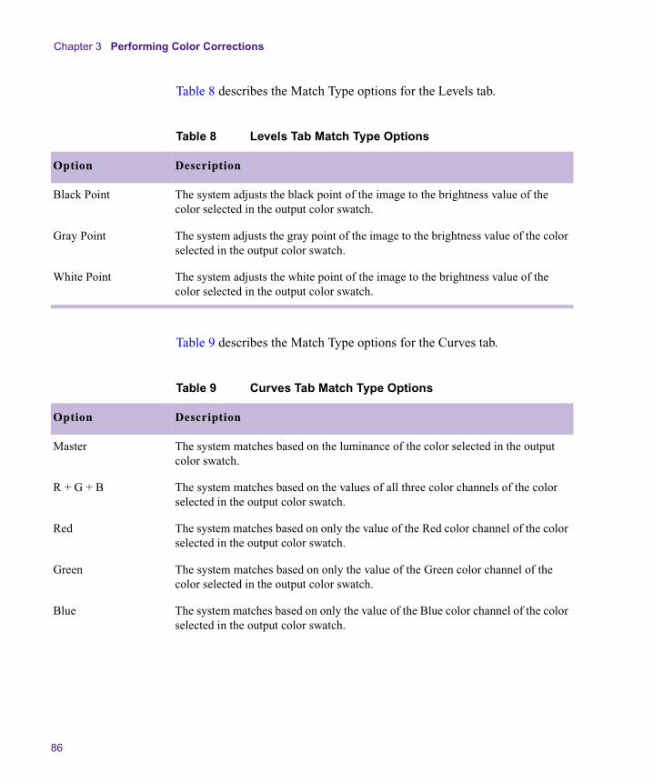
Chapter 3 Performing Color Corrections
86
Table 8 describes the Match Type options for the Levels tab.
Table 9 describes the Match Type options for the Curves tab.
Table 8 Levels Tab Match Type Options
Option Description
Black Point The system adjusts the black point of the image to the brightness value of the color selected in the output color swatch.
Gray Point The system adjusts the gray point of the image to the brightness value of the color selected in the output color swatch.
White Point The system adjusts the white point of the image to the brightness value of the color selected in the output color swatch.
Table 9 Curves Tab Match Type Options
Option Description
Master The system matches based on the luminance of the color selected in the output color swatch.
R + G + B The system matches based on the values of all three color channels of the color selected in the output color swatch.
Red The system matches based on only the value of the Red color channel of the color selected in the output color swatch.
Green The system matches based on only the value of the Green color channel of the color selected in the output color swatch.
Blue The system matches based on only the value of the Blue color channel of the color selected in the output color swatch.

Using the Color Match Control
87
Table 10 describes the Match Type options for the Secondary tab.
R + G The system matches based on the values of the Red and Green color channels of the color selected in the output color swatch.
R + B The system matches based on the values of the Red and Blue color channels of the color selected in the output color swatch.
G + B The system matches based on the values of the Green and Blue color channels of the color selected in the output color swatch.
NaturalMatch Select NaturalMatch to select or deselect the NaturalMatch feature.
When this command is selected, all the match types in the Curves and Secondary groups use NaturalMatch when making a correction and match types appear in the Color Match control with the extension (Nat). For more information on NaturalMatch, see “Understanding NaturalMatch” on page 88.
Table 9 Curves Tab Match Type Options (Continued)
Option Description
Table 10 Secondary Tab Match Type Options
Option Description
Hue The system matches based on only the hue of the color selected in the output color swatch.
Saturation The system matches based on only the saturation of the color selected in the output color swatch.
H + S The system matches based on both the hue and the saturation of the color selected in the output color swatch.
NaturalMatch Select NaturalMatch to select or deselect the NaturalMatch feature.
When this command is selected, all the match types in the Curves and Secondary groups use NaturalMatch when making a correction and match types appear in the Color Match control with the extension (Nat). For more information on NaturalMatch, see “Understanding NaturalMatch” on page 88.

Chapter 3 Performing Color Corrections
88
Understanding NaturalMatch
In many situations when you are correcting on a shot-to-shot basis, color matching is complicated by differences in lighting between one shot and another. For example, you might want to match the skin tone in Shot A, which is in shadow, with that in Shot B, which is brightly lit. To achieve a natural-looking correction, you need to replace the hue of Shot A while preserving luminance and saturation characteristics that suggest shadow.
NaturalMatch solves this problem by making calculations that compensate for the luminance and saturation qualities of the original image when making the correction. The correction that is made when you use NaturalMatch adopts the new hue value, preserves the original luminance value, and adjusts the saturation value in relation to the other values. NaturalMatch allows you to use the quick correction method offered by the Color Match control even when images show significant differences in lighting.
Color Match Example Using NaturalMatch
The following illustrations show an example of the use of the Color Match control and the NaturalMatch feature to correct color from shot to shot.
n If you are reading a hardcopy version of this document, you will find it useful to view the color images in the Help or in the online version of this document on the online publications CD-ROM.

Using the Color Match Control
89
This original image is very gray and shows poor skin tones. The RGB values for a point in the center of the man’s forehead are R:61, G:62, B:66 — an almost completely neutral gray.
Uncorrected Image
Though this image would benefit from further correction (particularly to improve the contrast ratio), it is improved dramatically as a result of the color match. The skin tones and the color of the tent in the background now match the reference image well.
Corrected Image
This image shows much better color characteristics, including good skin tones and a better color for the canvas of the tent. If we want to present these two shots next to one another in a sequence, we will almost certainly want to make their color characteristics match better. One way to do this is with the Color Match control. If we use the center of the forehead in the first image as an input value and the center of the forehead in this reference image (R:110, G:70, B:56) as an output value, and then make a Color Match using NaturalMatch to automatically generate Curves adjustments for all three color channels, we can quickly match the skin tones in the weak image to those in the better one.
Reference Image
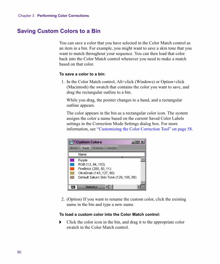
Chapter 3 Performing Color Corrections
90
Saving Custom Colors to a Bin
You can save a color that you have selected in the Color Match control as an item in a bin. For example, you might want to save a skin tone that you want to match throughout your sequence. You can then load that color back into the Color Match control whenever you need to make a match based on that color.
To save a color to a bin:
1. In the Color Match control, Alt+click (Windows) or Option+click (Macintosh) the swatch that contains the color you want to save, and drag the rectangular outline to a bin.
While you drag, the pointer changes to a hand, and a rectangular outline appears.
The color appears in the bin as a rectangular color icon. The system assigns the color a name based on the current Saved Color Labels settings in the Correction Mode Settings dialog box. For more information, see “Customizing the Color Correction Tool” on page 58.
2. (Option) If you want to rename the custom color, click the existing name in the bin and type a new name.
To load a custom color into the Color Match control:
t Click the color icon in the bin, and drag it to the appropriate color swatch in the Color Match control.
The HSL (Hue, Saturation, Luminance) Group
91
Getting RGB Information Using the Color Match Control
By default, the color swatches in the Color Match control display the RGB values for the selected color. This makes the Color Match control useful as an information palette to check the exact RGB value of a sample area in your image.
For example, if you have an area in your image that you know should appear white, you can sample that area using the Color Match eyedropper and check how far its RGB values depart from a true white. If the values are R:231, G:217, B:229, then you know that a little green needs to be added to achieve white. (In other words, the image has a magenta cast.) If you want this area in the image to be exactly reference white (R,G,B:235), you know that you also need to adjust the white point slightly to increase the RGB values.
The HSL (Hue, Saturation, Luminance) Group
The HSL (Hue, Saturation, Luminance) group provides controls that allow you to alter attributes such as hue, saturation, gain, and gamma. These controls resemble those found in the Video Input tool and in the Color Effect, and, therefore, HSL is the group in the Color Correction tool that will be most familiar to experienced Avid editors.
The HSL group also allows you to specify an offset for the hue of an image, a control that is especially useful for correcting a color cast. For example, when an object in an image that should be a neutral gray appears tinged with a color, you can use the offset adjustment to restore the correct gray color.
The HSL group provides additional control by allowing you to make adjustments in three different luminance ranges — highlights, midtones, and shadows. You can define the exact scope of each of these ranges and get visual confirmation of which parts of an image fall in each range. Having control over different luminance ranges is useful in a number of situations. For example, video images often contain chroma noise in the

Chapter 3 Performing Color Corrections
92
brightest and darkest areas. Using the HSL controls for the highlight and shadow ranges, you can make adjustments to reduce the noise without affecting the midtones in the image.
The HSL controls are capable of correcting a wide range of problems. If you are comfortable working with the HSL group and gain some experience using it, you might be able to make most of your common corrections without needing to employ any other group. For some kinds of adjustments, however, you might find the blending properties or the individual color channel control of other groups more suitable.
Working with the Controls Tab
The Controls tab of the HSL group includes sliders for making adjustments to hue, saturation, and luminance values. It also includes the Color Match control for making hue, saturation, and luminance adjustments automatically, based on selected input and output color values. For information on the Color Match control, see “Using the Color Match Control” on page 80.
The following illustration shows the Controls tab.

The HSL (Hue, Saturation, Luminance) Group
93
Making Corrections Using the Controls Tab
To make a color correction using the Controls tab:
1. If you have not already done so:
a. Move the position indicator to the segment you want to correct.
For more information on Source and Program sides and relationships, see Chapters 1 and 2.
b. Select a relationship from the Source or Program tab.
c. Click the HSL tab for the side (Source or Program) in which you want to work.
2. Click the Controls subdividing tab in the first vertical group on the left side of the Color Correction tool.
3. Click the appropriate subdividing tab in the second vertical group on the left side of the Color Correction tool.
This tab selection determines the brightness range across which your adjustments will apply. Table 11 describes the available options.
n By default, highlight, midtone, and shadow ranges represent equal one-third subdivisions of the full brightness range. You can customize these ranges using the controls in the Luma Ranges tab. For more information, see “Working with the Luma Ranges Tab” on page 105.
Table 11 Brightness Subdividing Tabs for the HSL Group
Tab Description
Master Adjustments apply to the whole image.
Highlights Adjustments apply to the brightest parts of the image only.
Midtones Adjustments apply to the midrange of brightness values only.
Shadows Adjustments apply to the darkest parts of the image only.
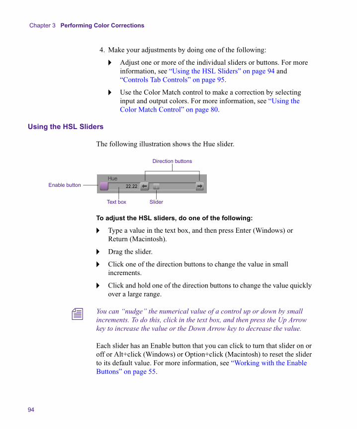
Chapter 3 Performing Color Corrections
94
4. Make your adjustments by doing one of the following:
t Adjust one or more of the individual sliders or buttons. For more information, see “Using the HSL Sliders” on page 94 and “Controls Tab Controls” on page 95.
t Use the Color Match control to make a correction by selecting input and output colors. For more information, see “Using the Color Match Control” on page 80.
Using the HSL Sliders
The following illustration shows the Hue slider.
To adjust the HSL sliders, do one of the following:
t Type a value in the text box, and then press Enter (Windows) or Return (Macintosh).
t Drag the slider.
t Click one of the direction buttons to change the value in small increments.
t Click and hold one of the direction buttons to change the value quickly over a large range.
n You can “nudge” the numerical value of a control up or down by small increments. To do this, click in the text box, and then press the Up Arrow key to increase the value or the Down Arrow key to decrease the value.
Each slider has an Enable button that you can click to turn that slider on or off or Alt+click (Windows) or Option+click (Macintosh) to reset the slider to its default value. For more information, see “Working with the Enable Buttons” on page 55.
Text box
Enable button
Direction buttons
Slider
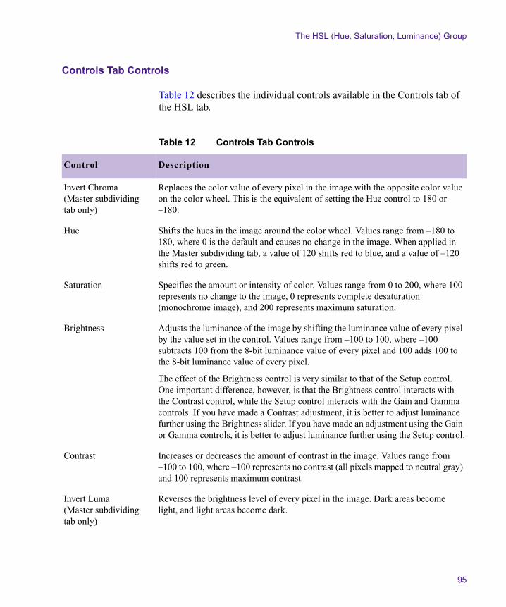
The HSL (Hue, Saturation, Luminance) Group
95
Controls Tab Controls
Table 12 describes the individual controls available in the Controls tab of the HSL tab.
Table 12 Controls Tab Controls
Control Description
Invert Chroma (Master subdividing tab only)
Replaces the color value of every pixel in the image with the opposite color value on the color wheel. This is the equivalent of setting the Hue control to 180 or –180.
Hue Shifts the hues in the image around the color wheel. Values range from –180 to 180, where 0 is the default and causes no change in the image. When applied in the Master subdividing tab, a value of 120 shifts red to blue, and a value of –120 shifts red to green.
Saturation Specifies the amount or intensity of color. Values range from 0 to 200, where 100 represents no change to the image, 0 represents complete desaturation (monochrome image), and 200 represents maximum saturation.
Brightness Adjusts the luminance of the image by shifting the luminance value of every pixel by the value set in the control. Values range from –100 to 100, where –100 subtracts 100 from the 8-bit luminance value of every pixel and 100 adds 100 to the 8-bit luminance value of every pixel.
The effect of the Brightness control is very similar to that of the Setup control. One important difference, however, is that the Brightness control interacts with the Contrast control, while the Setup control interacts with the Gain and Gamma controls. If you have made a Contrast adjustment, it is better to adjust luminance further using the Brightness slider. If you have made an adjustment using the Gain or Gamma controls, it is better to adjust luminance further using the Setup control.
Contrast Increases or decreases the amount of contrast in the image. Values range from –100 to 100, where –100 represents no contrast (all pixels mapped to neutral gray) and 100 represents maximum contrast.
Invert Luma (Master subdividing tab only)
Reverses the brightness level of every pixel in the image. Dark areas become light, and light areas become dark.
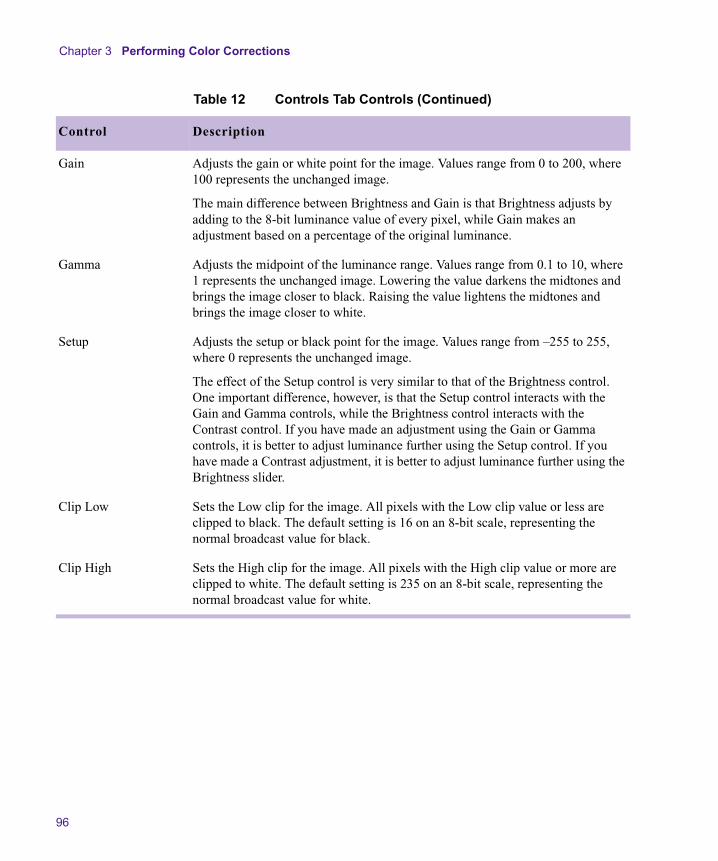
Chapter 3 Performing Color Corrections
96
Gain Adjusts the gain or white point for the image. Values range from 0 to 200, where 100 represents the unchanged image.
The main difference between Brightness and Gain is that Brightness adjusts by adding to the 8-bit luminance value of every pixel, while Gain makes an adjustment based on a percentage of the original luminance.
Gamma Adjusts the midpoint of the luminance range. Values range from 0.1 to 10, where 1 represents the unchanged image. Lowering the value darkens the midtones and brings the image closer to black. Raising the value lightens the midtones and brings the image closer to white.
Setup Adjusts the setup or black point for the image. Values range from –255 to 255, where 0 represents the unchanged image.
The effect of the Setup control is very similar to that of the Brightness control. One important difference, however, is that the Setup control interacts with the Gain and Gamma controls, while the Brightness control interacts with the Contrast control. If you have made an adjustment using the Gain or Gamma controls, it is better to adjust luminance further using the Setup control. If you have made a Contrast adjustment, it is better to adjust luminance further using the Brightness slider.
Clip Low Sets the Low clip for the image. All pixels with the Low clip value or less are clipped to black. The default setting is 16 on an 8-bit scale, representing the normal broadcast value for black.
Clip High Sets the High clip for the image. All pixels with the High clip value or more are clipped to white. The default setting is 235 on an 8-bit scale, representing the normal broadcast value for white.
Table 12 Controls Tab Controls (Continued)
Control Description

The HSL (Hue, Saturation, Luminance) Group
97
Working with the Hue Offsets Tab
The Hue Offsets tab of the HSL group includes controls for adjusting hue and saturation values at the same time using color wheels and linked text boxes. These controls are especially well-suited for correcting color casts in images.
n Since the Hue Offsets color wheels provide a control similar to the physical controllers on traditional color correction equipment, experienced colorists might choose to use them as their preferred controls for many color adjustments.
You can also use the Color Match control to automatically make a hue offset adjustment based on input and output colors. For information on the Color Match control, see “Using the Color Match Control” on page 80.
The following illustration shows the Hue Offsets tab.
Understanding the Hue Offsets Tab
The Hue Offsets tab includes four color wheels that allow you to make adjustments across the same luminance ranges as the Controls tab. The wheels are arranged in the following order from left to right: Shadows, Midtones, Highlights, and Master.
Color Match controlShadows color wheel
Midtones color wheel
Highlights color wheel
Master color wheel

Chapter 3 Performing Color Corrections
98
Hue Offsets Color Wheel Outline Display
The color wheels that display by default in the Hue Offsets tab are outlines that resemble the design of the Vectorscope monitor in the Video Input tool. Colors are oriented in the same manner as in the Vectorscope monitor, with red near the top. Axes indicate the offset in degrees from the 0° point, which corresponds with red.
n The Hue Offsets color wheels are designed to create a familiar environment for users by duplicating the general appearance of the Vectorscope monitor. They are not calibrated in the same way as in the Vectorscope monitor. For more information on the calibration of the Hue Offsets color wheels, see “Understanding the Hue Offsets Color Wheel” on page 99.
Displaying Hue Offsets Color Wheels in Full Color
You can choose to replace the outlines of the color wheels with full-color depictions that show the color represented by each area of the wheel. These full-color depictions can make it easier to understand the effect of a Hue Offsets adjustment; however, they create large areas of intense color in your monitor that can compete with the images in the Composer window.
To display the color wheels in full color:
1. Click the Correction Mode Settings button.
The Correction Mode Settings dialog box opens.
2. Click the Features tab.
3. Select Show Color Wheels.
The following illustration shows the Hue Offsets tab with Show Color Wheels selected.
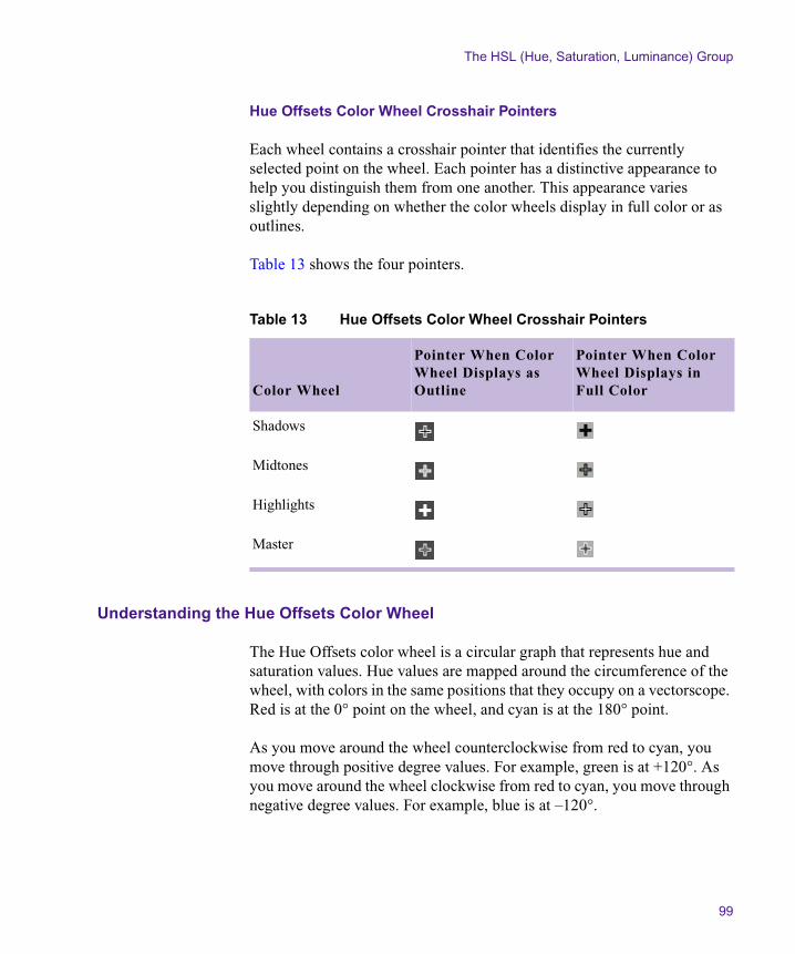
The HSL (Hue, Saturation, Luminance) Group
99
Hue Offsets Color Wheel Crosshair Pointers
Each wheel contains a crosshair pointer that identifies the currently selected point on the wheel. Each pointer has a distinctive appearance to help you distinguish them from one another. This appearance varies slightly depending on whether the color wheels display in full color or as outlines.
Table 13 shows the four pointers.
Understanding the Hue Offsets Color Wheel
The Hue Offsets color wheel is a circular graph that represents hue and saturation values. Hue values are mapped around the circumference of the wheel, with colors in the same positions that they occupy on a vectorscope. Red is at the 0° point on the wheel, and cyan is at the 180° point.
As you move around the wheel counterclockwise from red to cyan, you move through positive degree values. For example, green is at +120°. As you move around the wheel clockwise from red to cyan, you move through negative degree values. For example, blue is at –120°.
Table 13 Hue Offsets Color Wheel Crosshair Pointers
Color Wheel
Pointer When Color Wheel Displays as Outline
Pointer When Color Wheel Displays in Full Color
Shadows
Midtones
Highlights
Master

Chapter 3 Performing Color Corrections
100
Saturation values are mapped along the radius of the wheel. The center point of the wheel represents zero saturation (neutral gray); the edge of the wheel represents maximum saturation. As you move out from the center of the wheel, you shift from less to more saturation. Saturation values are measured on a scale from 0 (zero saturation) to 100 (maximum saturation).
By picking a specific point on the wheel, you select an exact combination of hue and color intensity to add to your image. You can select a gray with a slight yellow tinge near the center of the wheel, for example, or an intensely saturated blue at the outer edge.
n If you are reading a hardcopy version of this document, you will find it useful to view the color images in the Help or in the online version of this document on the online publications CD-ROM.
Saturation increases from the center of the wheel toward the edge.
Hue changes as you move around the wheel.
When displayed as an outline, the color wheel shows the degree values for measuring hue.
The HSL (Hue, Saturation, Luminance) Group
101
When you use the color wheel to correct a color cast, you use a basic principle of color theory: you can cancel out one color in an image by adding an equal amount of the opposite color on the wheel. For example, to remove a red cast, add some cyan. To remove a yellow cast, add some blue. You do not even need to remember which colors are opposite when you have the color wheel as a control. Simply add some color from the opposite side of the wheel from the color you want to remove, and then fine-tune your adjustment until you are satisfied with the result.
Making Corrections Using the Hue Offsets Tab
To make a correction using the Hue Offsets tab:
1. If you have not already done so:
a. Move the position indicator to the segment you want to correct.
For more information on Source and Program sides and relationships, see Chapters 1 and 2.
b. Select a relationship from the Source or Program tab.
c. Click the HSL tab for the side (Source or Program) in which you want to work.
2. Click the Hue Offsets subdividing tab in the first vertical group on the left side of the Color Correction tool.
3. Make your adjustments by doing one or more of the following:
t Move the crosshair pointer on the appropriate color wheel. For more information, see “Moving the Color Wheel Crosshair Pointers” on page 102.
As you move the pointer in the wheel, the Hue and Amt (Amount) text boxes update to display numerical values for the adjustment.
t Type values in the Hue and Amt text boxes for the appropriate color wheel to set the offset you want. You must press Enter (Windows) or Return (Macintosh) after typing a value for it to take effect.
Hue values range from –180° to 180° where 0° is the position of red on the wheel. Amount values range from 0 to 100. When you change the Hue and Amount values, the pointer on the color wheel updates to represent the adjustment.
Chapter 3 Performing Color Corrections
102
n You can “nudge” the numerical value of a control up or down by small increments. To do this, click in the text box, and then press the Up Arrow key to increase the value or the Down Arrow key to decrease the value.
t Use the Color Match control to calculate an offset automatically, based on input and output colors. For more information, see “Using the Color Match Control” on page 80.
4. Fine-tune your adjustments until you are satisfied with the result.
Remember that you can make adjustments on more than one color wheel and turn them on and off individually to assess their effect on the image.
Moving the Color Wheel Crosshair Pointers
To move the crosshair pointer in a color wheel:
1. Position the pointer anywhere in the wheel, and press and hold the mouse button.
The standard mouse pointer disappears, and the crosshair pointer is dynamically linked to the mouse.
2. Drag the crosshair pointer around in the wheel until you are satisfied with the adjustment, and then release the mouse button.
n For more precise control over the movement of the crosshair pointer in the central area of the wheel, press and hold the Shift key while performing the actions in this procedure.
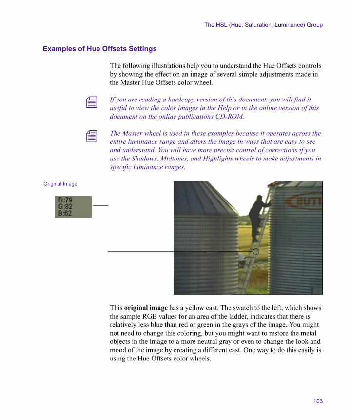
The HSL (Hue, Saturation, Luminance) Group
103
Examples of Hue Offsets Settings
The following illustrations help you to understand the Hue Offsets controls by showing the effect on an image of several simple adjustments made in the Master Hue Offsets color wheel.
n If you are reading a hardcopy version of this document, you will find it useful to view the color images in the Help or in the online version of this document on the online publications CD-ROM.
n The Master wheel is used in these examples because it operates across the entire luminance range and alters the image in ways that are easy to see and understand. You will have more precise control of corrections if you use the Shadows, Midtones, and Highlights wheels to make adjustments in specific luminance ranges.
This original image has a yellow cast. The swatch to the left, which shows the sample RGB values for an area of the ladder, indicates that there is relatively less blue than red or green in the grays of the image. You might not need to change this coloring, but you might want to restore the metal objects in the image to a more neutral gray or even to change the look and mood of the image by creating a different cast. One way to do this easily is using the Hue Offsets color wheels.
Original Image

Chapter 3 Performing Color Corrections
104
Adjustment 1 alters the original image by introducing just enough blue to make the grays in the image neutral. The RGB values in the ladder now show almost equal amounts of red, green, and blue. The yellow cast is corrected by moving the crosshair pointer in the color wheel in the opposite direction from yellow.
Adjustment 2 increases the intensity of the blue that is being added to the original image. Metal objects in the image are now distinctly blue-gray, and the sample values from the ladder show more blue than red or green.
Adjustment 1
Adjustment 2
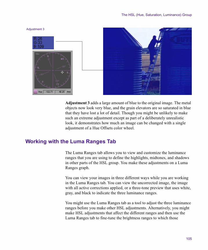
The HSL (Hue, Saturation, Luminance) Group
105
Adjustment 3 adds a large amount of blue to the original image. The metal objects now look very blue, and the grain elevators are so saturated in blue that they have lost a lot of detail. Though you might be unlikely to make such an extreme adjustment except as part of a deliberately unrealistic look, it demonstrates how much an image can be changed with a single adjustment of a Hue Offsets color wheel.
Working with the Luma Ranges Tab
The Luma Ranges tab allows you to view and customize the luminance ranges that you are using to define the highlights, midtones, and shadows in other parts of the HSL group. You make these adjustments on a Luma Ranges graph.
You can view your images in three different ways while you are working in the Luma Ranges tab. You can view the uncorrected image, the image with all active corrections applied, or a three-tone preview that uses white, gray, and black to indicate the three luminance ranges.
You might use the Luma Ranges tab as a tool to adjust the three luminance ranges before you make other HSL adjustments. Alternatively, you might make HSL adjustments that affect the different ranges and then use the Luma Ranges tab to fine-tune the brightness ranges to which those
Adjustment 3

Chapter 3 Performing Color Corrections
106
adjustments apply. For example, you can make an adjustment that you like in the Highlights wheel of the Hue Offsets tab and then fine-tune the range of pixels to which that adjustment applies using the Luma Ranges tab.
The following illustration shows the Luma Ranges tab with the Highlights subdividing tab displayed.
Understanding the Luma Ranges Graph
The Luma Ranges graph shows curves for each of the three luminance ranges: highlights, midtones, and shadows. You can always see all three curves, but you can make adjustments only to the curve that is active as defined by your subdividing tab.
The graph plots brightness values from 0 to 255 on the horizontal axis and percentage values on the vertical axis. The system defines a luminance range as the area in the graph where the curve for that range is highest in the graph. The following illustration shows this arrangement for the default curves.
Preview buttons Text boxes Luma Ranges graph
Shadows Midtones Highlights
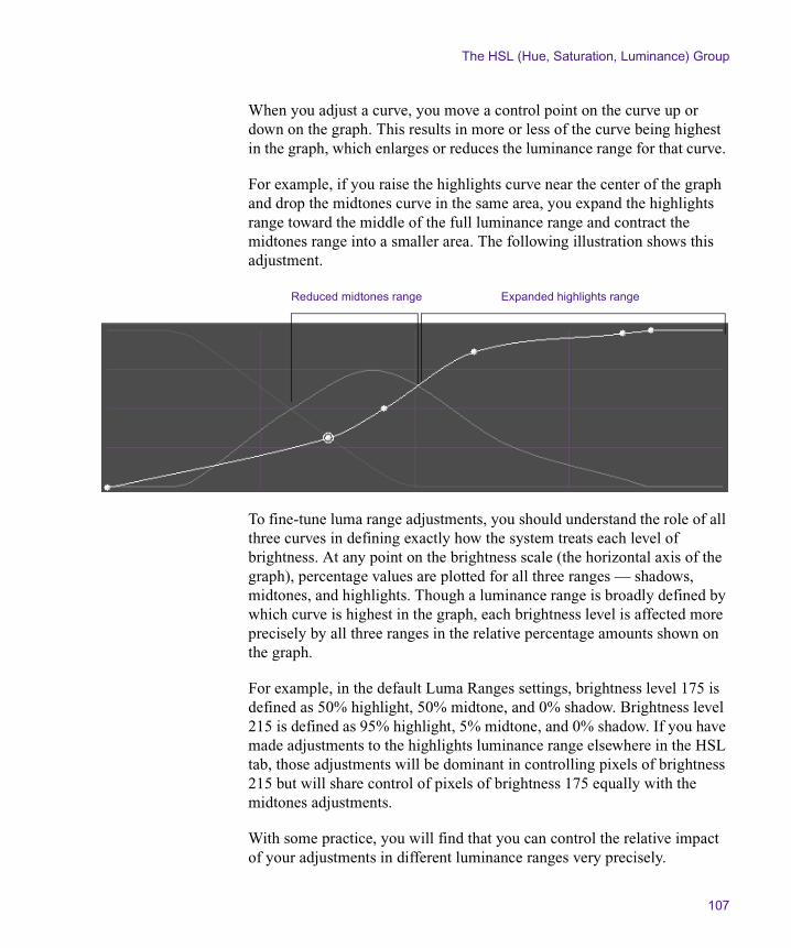
The HSL (Hue, Saturation, Luminance) Group
107
When you adjust a curve, you move a control point on the curve up or down on the graph. This results in more or less of the curve being highest in the graph, which enlarges or reduces the luminance range for that curve.
For example, if you raise the highlights curve near the center of the graph and drop the midtones curve in the same area, you expand the highlights range toward the middle of the full luminance range and contract the midtones range into a smaller area. The following illustration shows this adjustment.
To fine-tune luma range adjustments, you should understand the role of all three curves in defining exactly how the system treats each level of brightness. At any point on the brightness scale (the horizontal axis of the graph), percentage values are plotted for all three ranges — shadows, midtones, and highlights. Though a luminance range is broadly defined by which curve is highest in the graph, each brightness level is affected more precisely by all three ranges in the relative percentage amounts shown on the graph.
For example, in the default Luma Ranges settings, brightness level 175 is defined as 50% highlight, 50% midtone, and 0% shadow. Brightness level 215 is defined as 95% highlight, 5% midtone, and 0% shadow. If you have made adjustments to the highlights luminance range elsewhere in the HSL tab, those adjustments will be dominant in controlling pixels of brightness 215 but will share control of pixels of brightness 175 equally with the midtones adjustments.
With some practice, you will find that you can control the relative impact of your adjustments in different luminance ranges very precisely.
Expanded highlights rangeReduced midtones range
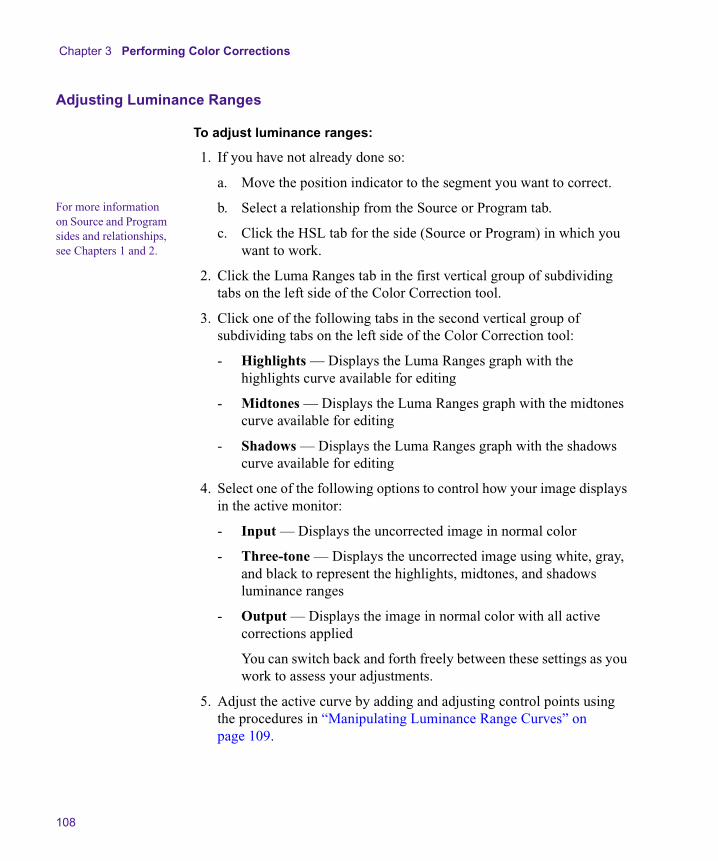
Chapter 3 Performing Color Corrections
108
Adjusting Luminance Ranges
To adjust luminance ranges:
1. If you have not already done so:
a. Move the position indicator to the segment you want to correct.
For more information on Source and Program sides and relationships, see Chapters 1 and 2.
b. Select a relationship from the Source or Program tab.
c. Click the HSL tab for the side (Source or Program) in which you want to work.
2. Click the Luma Ranges tab in the first vertical group of subdividing tabs on the left side of the Color Correction tool.
3. Click one of the following tabs in the second vertical group of subdividing tabs on the left side of the Color Correction tool:
- Highlights — Displays the Luma Ranges graph with the highlights curve available for editing
- Midtones — Displays the Luma Ranges graph with the midtones curve available for editing
- Shadows — Displays the Luma Ranges graph with the shadows curve available for editing
4. Select one of the following options to control how your image displays in the active monitor:
- Input — Displays the uncorrected image in normal color
- Three-tone — Displays the uncorrected image using white, gray, and black to represent the highlights, midtones, and shadows luminance ranges
- Output — Displays the image in normal color with all active corrections applied
You can switch back and forth freely between these settings as you work to assess your adjustments.
5. Adjust the active curve by adding and adjusting control points using the procedures in “Manipulating Luminance Range Curves” on page 109.

The HSL (Hue, Saturation, Luminance) Group
109
Manipulating Luminance Range Curves
To add a control point to a curve:
t Click the curve at the point where you want to move it.
A new control point appears with a circle around it to indicate that it is the active point.
To move a control point:
1. Click the control point to activate it.
A circle appears around the control point.
2. Do one of the following:
t Click the point on the graph, and drag it until the curve is in the position you want.
t Type values in the In and Out text boxes to define the position of the point on the graph. You must press Enter (Windows) or Return (Macintosh) after typing a value for it to take effect.
n You can “nudge” the numerical value of a control up or down by small increments. To do this, click in the text box, and then press the Up Arrow key to increase the value or the Down Arrow key to decrease the value.
To delete a control point:
t Click the point to activate it, and then press the Delete key.
Examples of Three-Tone Previews
The following illustrations show sample three-tone previews for a typical video image and for a test monochrome gradient.
n If you are reading a hardcopy version of this document, you will find it useful to view the color images in the Help or in the online version of this document on the online publications CD-ROM.
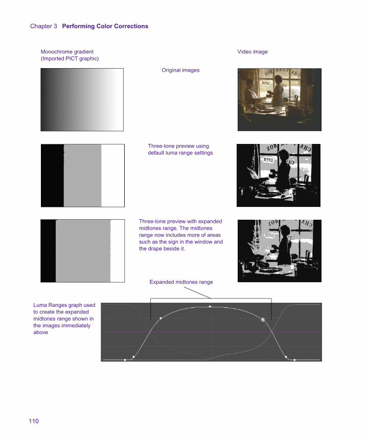
Chapter 3 Performing Color Corrections
110
Monochrome gradient (Imported PICT graphic)
Video image
Original images
Three-tone preview using default luma range settings
Three-tone preview with expanded midtones range. The midtones range now includes more of areas such as the sign in the window and the drape beside it.
Expanded midtones range
Luma Ranges graph used to create the expanded midtones range shown in the images immediately above

The Channels Group
111
The Channels Group
The Channels group provides controls that allow you to redefine each output color channel (red, green, blue) by blending different input color components in various proportions. You can work with components from both the RGB (red, green, blue) and the YCrCb (luminance, red chroma, blue chroma) color spaces. Because you can blend up to four input components to create each output color channel, the Channels group offers very precise control over the final composition of each color channel.
The Channels group also enables you to preview the individual color channels in monochrome. This is useful for checking the amount of contrast or noise in each channel.
The Channels group is particularly useful for identifying a color channel that is deficient in some way — one that is lacking in contrast or is noisy, for example — and repairing it by “borrowing” from another color channel. For some kinds of images, borrowing in this way is the only way to improve the appearance of the image significantly.
For example, you might preview the input channels for a segment and notice that, although the master input shows acceptable overall contrast, the green channel is clipped to white and has therefore lost contrast in the highlight range. It is not possible to “unclip” these green highlights by working in the existing green channel, since the brightness value of all the pixels in the highlight range is the same (or very nearly so). The best solution to this problem is to blend a percentage of one of the other channels into the green channel to reintroduce some contrast and detail. You might redefine the green channel as 80% green and 20% red to solve the problem.
As in other groups, you can use the Color Match control to set the blending controls automatically, based on selected input and output colors. For information on the Color Match control, see “Using the Color Match Control” on page 80.

Chapter 3 Performing Color Corrections
112
The following illustration shows the Channels tab in its default configuration.
Making Corrections Using the Channels Tab
To make corrections using the Channels tab:
1. If you have not already done so:
a. Move the position indicator to the segment you want to correct.
For more information on Source and Program sides and relationships, see Chapters 1 and 2.
b. Select a relationship from the Source or Program tab.
c. Click the Channels tab for the side (Source or Program) in which you want to work.
2. Preview the input image by selecting an input type in the Preview pane:
- Red Input — Displays the uncorrected red channel in monochrome
- Green Input — Displays the uncorrected green channel in monochrome
- Blue Input — Displays the uncorrected blue channel in monochrome
- Master Input — Displays the complete uncorrected image in color
For more information on previewing options, see “Considerations When Working with Color Components” on page 115.
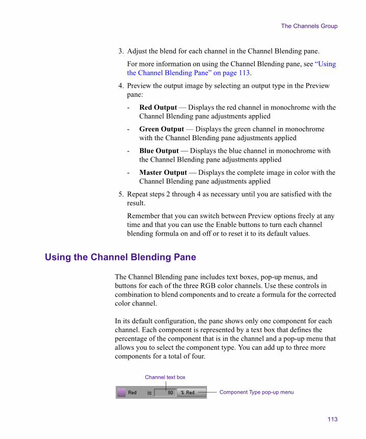
The Channels Group
113
3. Adjust the blend for each channel in the Channel Blending pane.
For more information on using the Channel Blending pane, see “Using the Channel Blending Pane” on page 113.
4. Preview the output image by selecting an output type in the Preview pane:
- Red Output — Displays the red channel in monochrome with the Channel Blending pane adjustments applied
- Green Output — Displays the green channel in monochrome with the Channel Blending pane adjustments applied
- Blue Output — Displays the blue channel in monochrome with the Channel Blending pane adjustments applied
- Master Output — Displays the complete image in color with the Channel Blending pane adjustments applied
5. Repeat steps 2 through 4 as necessary until you are satisfied with the result.
Remember that you can switch between Preview options freely at any time and that you can use the Enable buttons to turn each channel blending formula on and off or to reset it to its default values.
Using the Channel Blending Pane
The Channel Blending pane includes text boxes, pop-up menus, and buttons for each of the three RGB color channels. Use these controls in combination to blend components and to create a formula for the corrected color channel.
In its default configuration, the pane shows only one component for each channel. Each component is represented by a text box that defines the percentage of the component that is in the channel and a pop-up menu that allows you to select the component type. You can add up to three more components for a total of four.
Channel text box
Component Type pop-up menu
Chapter 3 Performing Color Corrections
114
To select a component type:
t Click the Component Type pop-up menu, and select a type.
Table 14 describes the available options.
To adjust the amount of a component in the blend:
t Type a value in the text box for the component, and then press Enter (Windows) or Return (Macintosh). Values can range from –200% to 200%.
n You can “nudge” the numerical value of a control up or down by small increments. To do this, click in the text box, and then press the Up Arrow key to increase the value or the Down Arrow key to decrease the value.
Table 14 Component Type Options in the Channels Tab
Option Description
Red The input red channel
Green The input green channel
Blue The input blue channel
Luma The luminance channel in the component video signal
Cr The red chroma channel in the component video signal
Cb The blue chroma channel in the component video signal
Offset A constant value that adjusts all the other values in the formula
Invert This option subtracts the component from the overall formula instead of adding it. Select one of the other options, and then select Invert to invert it. A minus sign (–) appears after the component name when it is inverted. This has the same effect as entering a negative value for a component: 20% Green – is the same as –20% Green.
The Channels Group
115
To add a new component to the formula for a channel:
t Click the more button to the right of the existing components.
The more button changes to a plus (+) button, and a new set of component controls appears to the right of the button.
To remove components from the formula:
t Click the plus (+) button to the left of the components you want to remove.
The system removes all components to the right of the plus (+) button you click.
Considerations When Working with Color Components
When you find that one of your color channels has a problem that you want to correct by blending, you need to look for another color component that can correct the problem while minimizing any unwanted changes. In general, you should look for a component that exhibits less of the specific problem you want to correct but that otherwise looks similar to the problem channel.
You do not have to restrict your component choices to the same color space (RGB or YCrCb). In fact, it is common practice when performing advanced color correction to borrow from a different color space. For example, if you have a green channel that is noisy in the highlight range, you might find that the Cb (blue chroma) component has less highlight noise but is otherwise similar in its brightness distribution to the green channel. Blending a percentage of Cb into the green channel will reduce the noise without greatly disturbing other aspects of the channel.
You can preview the full range of color components available by temporarily redefining one of the existing channels. For example, if you want to see what the Cb component looks like in comparison to your problem green channel, you can redefine the red channel as 100% Cb. Then you can switch back and forth between the Red Input and Green Input previews to compare the two.

Chapter 3 Performing Color Corrections
116
n The total of the percentages you set for a channel does not need to be 100. The percentage values simply indicate relative proportions of one component as opposed to others.
Examples of Channel Blending Settings
The following illustrations show two representative Channel Blending settings for the red channel.
The following detailed example shows how an individual channel is altered by blending.
n If you are reading a hardcopy version of this document, you will find it useful to view the color images in the Help or in the online version of this document on the online publications CD-ROM.
The Blue Input monochrome preview shows that the blue channel lacks contrast. Blending 25% of the green channel information into the blue channel (as shown in the illustration of the controls) introduces somewhat more contrast into the blue channel.
The effect on the Master image in this case is not dramatic; this might or might not be desirable, depending on your project needs. A little extra detail has been obtained in the lower half of the image, but the color characteristics have changed so that the image is less intensely yellow. This probably improves the look of the sky; however, it reduces the strength of the yellow color in the sunflowers.
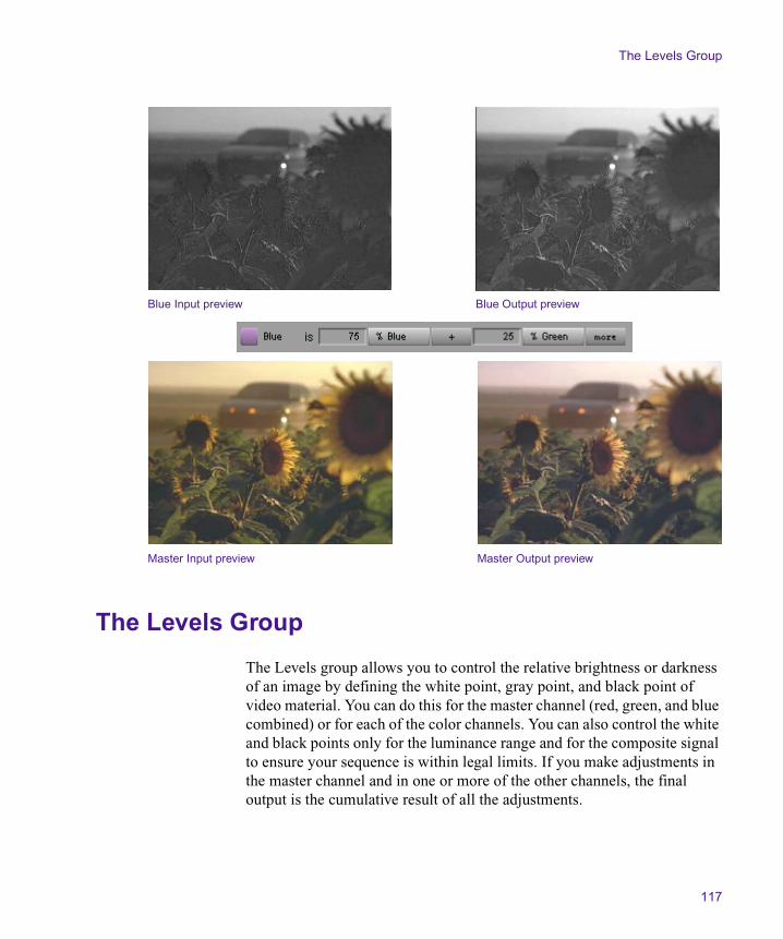
The Levels Group
117
The Levels Group
The Levels group allows you to control the relative brightness or darkness of an image by defining the white point, gray point, and black point of video material. You can do this for the master channel (red, green, and blue combined) or for each of the color channels. You can also control the white and black points only for the luminance range and for the composite signal to ensure your sequence is within legal limits. If you make adjustments in the master channel and in one or more of the other channels, the final output is the cumulative result of all the adjustments.
Blue Input preview Blue Output preview
Master Input preview Master Output preview

Chapter 3 Performing Color Corrections
118
There are four different ways to define the white, gray, and black points. You can type numerical values, adjust sliders on a histogram control, move control points on a Curve graph, or use the Color Match control to set points automatically, based on selected input and output colors. For information on the Color Match control, see “Using the Color Match Control” on page 80.
The main use of the Levels group is to rebalance the color or luma range. The group provides a great deal of control over the amount of contrast and detail visible in the video image, especially since you can make adjustments on the individual color channels. The Levels group is, therefore, a more refined and specialized version of the Gain, Gamma, and Setup controls in the HSL tab.
You might want to extend the range of contrast and detail in an image that lacks a full range (either in one color channel or across all the color channels), or you might want to deliberately reduce detail in part of the range (perhaps to expand another part of the range that is more important in the image). You might also want to adjust the gray point with respect to the black and white points in order to rebalance the midtones without significantly affecting the highlights and shadows.
It is important to understand the difference between a circumstance in which detail can be enhanced with the Levels group and one in which a blending adjustment in the Channels group is more useful. If a channel (for example, green) is clipped to white, then it does not contain enough information to contribute much detail; it must be repaired by borrowing contrast from another color component in the manner described in “The Channels Group” on page 111. If, however, the green channel contains an acceptable range of tones but they are shifted toward the highlight end of the brightness range, resetting the black point in the Levels group will improve contrast and detail by spreading the available information over a bigger range.

The Levels Group
119
The following illustration shows the Levels tab in its default configuration.
Understanding Input and Output Levels Adjustments
When you make an adjustment in the Levels tab, you are changing the relationship between input and output values for your image. You can make adjustments on both the input and the output side, and understanding the differences between input and output adjustments is important.
Examples of Black Point Input and Output Adjustments
A typical default setup for the Levels tab will show the following values on both the input and the output side:
The black point and white point values represent normal, safe limits for video broadcast.
Subdividing tabs
Input histogram
Input text boxes Curve graph
Output histogram
Color Match controlOutput text boxes
Black Point Gray Point White Point
16 128 235
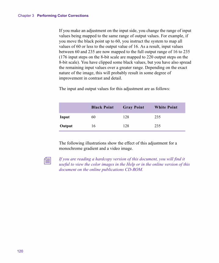
Chapter 3 Performing Color Corrections
120
If you make an adjustment on the input side, you change the range of input values being mapped to the same range of output values. For example, if you move the black point up to 60, you instruct the system to map all values of 60 or less to the output value of 16. As a result, input values between 60 and 235 are now mapped to the full output range of 16 to 235 (176 input steps on the 8-bit scale are mapped to 220 output steps on the 8-bit scale). You have clipped some black values, but you have also spread the remaining input values over a greater range. Depending on the exact nature of the image, this will probably result in some degree of improvement in contrast and detail.
The input and output values for this adjustment are as follows:
The following illustrations show the effect of this adjustment for a monochrome gradient and a video image.
n If you are reading a hardcopy version of this document, you will find it useful to view the color images in the Help or in the online version of this document on the online publications CD-ROM.
Black Point Gray Point White Point
Input 60 128 235
Output 16 128 235
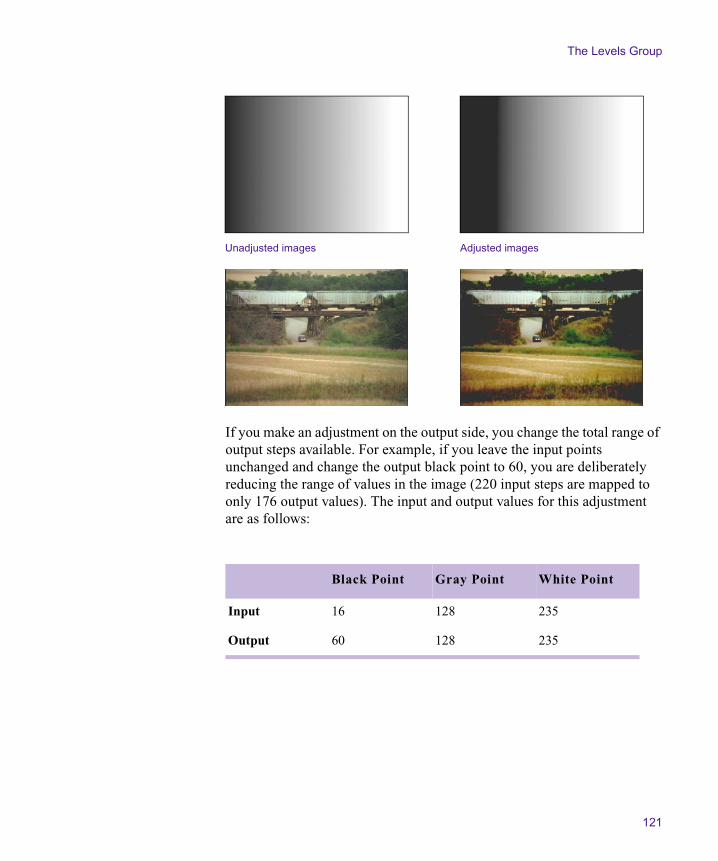
The Levels Group
121
If you make an adjustment on the output side, you change the total range of output steps available. For example, if you leave the input points unchanged and change the output black point to 60, you are deliberately reducing the range of values in the image (220 input steps are mapped to only 176 output values). The input and output values for this adjustment are as follows:
Unadjusted images Adjusted images
Black Point Gray Point White Point
Input 16 128 235
Output 60 128 235
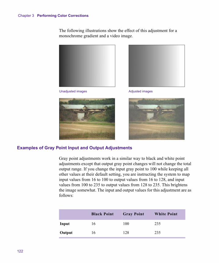
Chapter 3 Performing Color Corrections
122
The following illustrations show the effect of this adjustment for a monochrome gradient and a video image.
Examples of Gray Point Input and Output Adjustments
Gray point adjustments work in a similar way to black and white point adjustments except that output gray point changes will not change the total output range. If you change the input gray point to 100 while keeping all other values at their default setting, you are instructing the system to map input values from 16 to 100 to output values from 16 to 128, and input values from 100 to 235 to output values from 128 to 235. This brightens the image somewhat. The input and output values for this adjustment are as follows:
Unadjusted images Adjusted images
Black Point Gray Point White Point
Input 16 100 235
Output 16 128 235
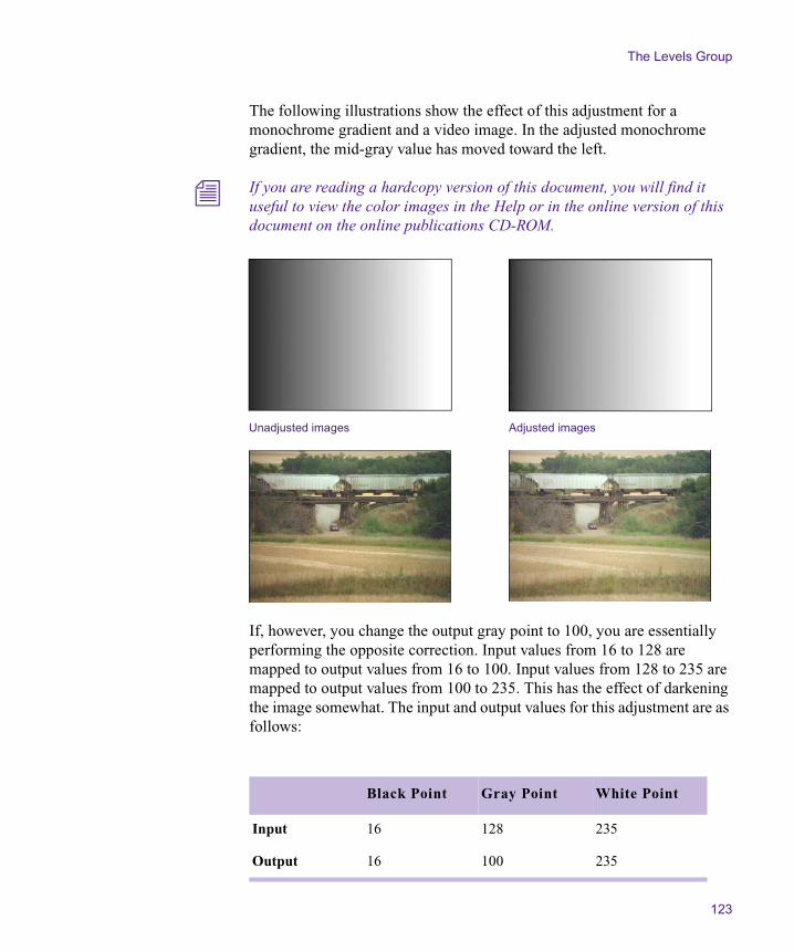
The Levels Group
123
The following illustrations show the effect of this adjustment for a monochrome gradient and a video image. In the adjusted monochrome gradient, the mid-gray value has moved toward the left.
n If you are reading a hardcopy version of this document, you will find it useful to view the color images in the Help or in the online version of this document on the online publications CD-ROM.
If, however, you change the output gray point to 100, you are essentially performing the opposite correction. Input values from 16 to 128 are mapped to output values from 16 to 100. Input values from 128 to 235 are mapped to output values from 100 to 235. This has the effect of darkening the image somewhat. The input and output values for this adjustment are as follows:
Unadjusted images Adjusted images
Black Point Gray Point White Point
Input 16 128 235
Output 16 100 235

Chapter 3 Performing Color Corrections
124
The following illustrations show the effect of this adjustment for a monochrome gradient and a video image.
Making Corrections Using the Levels Tab
To make corrections using the Levels tab:
1. If you have not already done so:
a. Move the position indicator to the segment you want to correct.
For more information on Source and Program sides and relationships, see Chapters 1 and 2.
b. Select a relationship from the Source or Program tab.
c. Click the Levels tab for the side (Source or Program) in which you want to work.
Unadjusted images Adjusted images
The Levels Group
125
2. Click the appropriate subdividing tab on the left side of the Color Correction tool.
The subdividing tab selects the type of levels adjustment you want to make. The following options are available:
- Composite — Allows you to adjust high and low points for the composite signal to ensure that your sequence remains within legal composite limits
- Luma — Allows you to adjust levels based on luminance values only
n Controls in the Composite and Luma tabs work slightly differently from those in the other Levels tabs. For more information on working with the Composite and Luma tabs, see “Working with the Composite and Luma Tabs” on page 132.
- Red — Allows you to adjust levels for the red channel only
- Green — Allows you to adjust levels for the green channel only
- Blue — Allows you to adjust levels for the blue channel only
- Master — Allows you to adjust levels for all three color channels
3. Make adjustments to the controls until you are satisfied with the result.
For more information on the individual controls and how to use them, see “Working with the Levels Tab Controls” on page 126.
Chapter 3 Performing Color Corrections
126
Working with the Levels Tab Controls
The following sections provide detailed explanations of the different controls in the Levels tab and how to use them.
The Levels controls are dynamically linked. When you make an adjustment to one of the controls, that adjustment is reflected in all other appropriate controls. For example, if you change the input black point value in the text box, the histogram slider and the control point for black on the Curve graph will change.
Understanding Histograms
A histogram is a graph of information about the color values of all the pixels in an image. Color values are plotted on the horizontal axis of the graph; the number of pixels is plotted on the vertical axis. For example, if an image contains 120 pixels of color value 30, then a bar 120 units high appears at the 30 point along the horizontal axis. A background grid indicates the quartile points on each axis to assist you when you are reading the graph and making adjustments.
Histograms provide an easily understood summary of the color range of an image. If an image is mostly dark, the bars of its histogram are concentrated at the low end. If an image contains only a small number of discrete color values, its histogram shows discrete spikes for each of those values. The following illustrations show several examples of histogram patterns.
n If you are reading a hardcopy version of this document, you will find it useful to view the color images in the Help or in the online version of this document on the online publications CD-ROM.

The Levels Group
127
This image has large areas that are very dark and a relatively even distribution of values in the rest of the brightness range. The histogram shows a sharp spike at the very low end, a concentration of values in the lowest 25% of the range, and a relatively even distribution in the rest of the range.
This image, like the last, has more dark values than light. But the distribution of values is less extreme, and this is reflected in the histogram, which shows a more rounded peak at the low end, fewer extremely low values, and relatively more midtone values.
Example 3: This image has very large highlight areas in the background and on the chicks. Most of the rest of the image is relatively, but not extremely, dark. The histogram shows sharp spikes at the high end, relative concentration in the low to middle range, and few values in the middle to high range.
Example 3
Example 1
Example 2
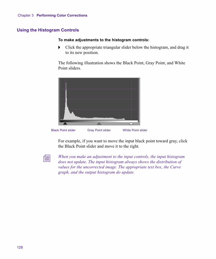
Chapter 3 Performing Color Corrections
128
Using the Histogram Controls
To make adjustments to the histogram controls:
t Click the appropriate triangular slider below the histogram, and drag it to its new position.
The following illustration shows the Black Point, Gray Point, and White Point sliders.
For example, if you want to move the input black point toward gray, click the Black Point slider and move it to the right.
n When you make an adjustment to the input controls, the input histogram does not update. The input histogram always shows the distribution of values for the uncorrected image. The appropriate text box, the Curve graph, and the output histogram do update.
Black Point slider Gray Point slider White Point slider
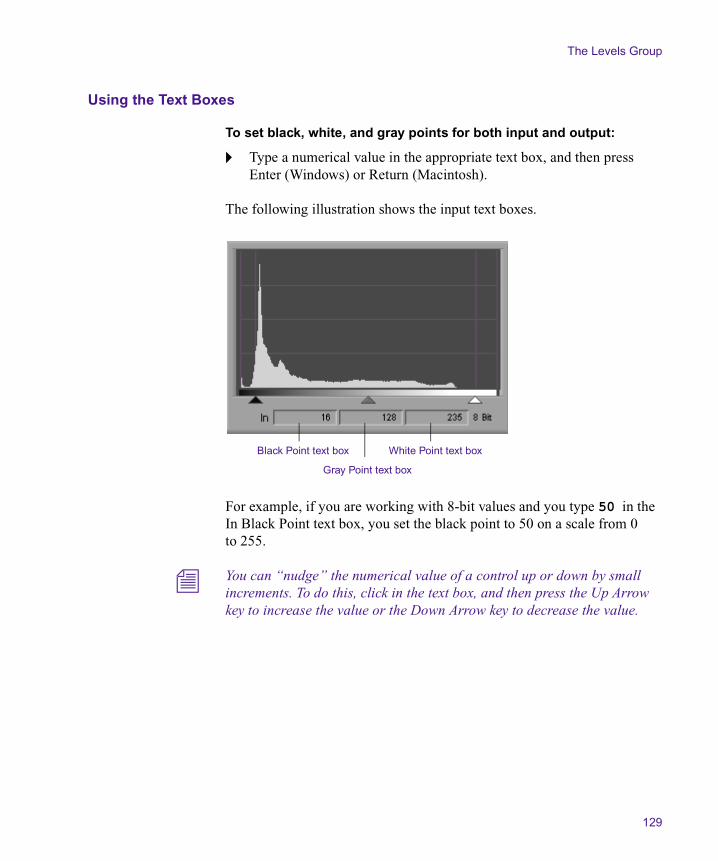
The Levels Group
129
Using the Text Boxes
To set black, white, and gray points for both input and output:
t Type a numerical value in the appropriate text box, and then press Enter (Windows) or Return (Macintosh).
The following illustration shows the input text boxes.
For example, if you are working with 8-bit values and you type 50 in the In Black Point text box, you set the black point to 50 on a scale from 0 to 255.
n You can “nudge” the numerical value of a control up or down by small increments. To do this, click in the text box, and then press the Up Arrow key to increase the value or the Down Arrow key to decrease the value.
Black Point text box White Point text box
Gray Point text box
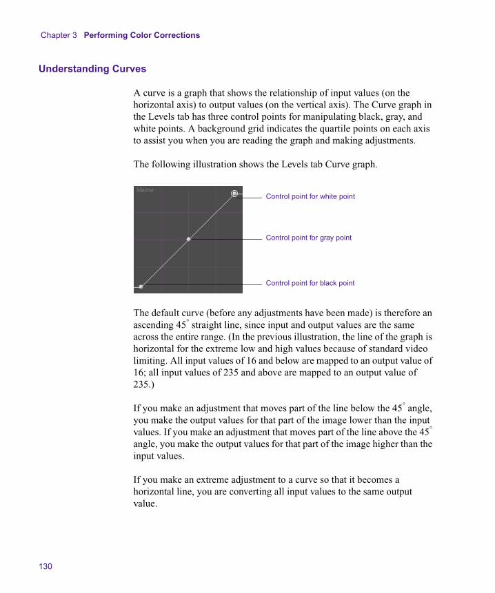
Chapter 3 Performing Color Corrections
130
Understanding Curves
A curve is a graph that shows the relationship of input values (on the horizontal axis) to output values (on the vertical axis). The Curve graph in the Levels tab has three control points for manipulating black, gray, and white points. A background grid indicates the quartile points on each axis to assist you when you are reading the graph and making adjustments.
The following illustration shows the Levels tab Curve graph.
The default curve (before any adjustments have been made) is therefore an ascending 45° straight line, since input and output values are the same across the entire range. (In the previous illustration, the line of the graph is horizontal for the extreme low and high values because of standard video limiting. All input values of 16 and below are mapped to an output value of 16; all input values of 235 and above are mapped to an output value of 235.)
If you make an adjustment that moves part of the line below the 45° angle, you make the output values for that part of the image lower than the input values. If you make an adjustment that moves part of the line above the 45° angle, you make the output values for that part of the image higher than the input values.
If you make an extreme adjustment to a curve so that it becomes a horizontal line, you are converting all input values to the same output value.
Control point for white point
Control point for gray point
Control point for black point
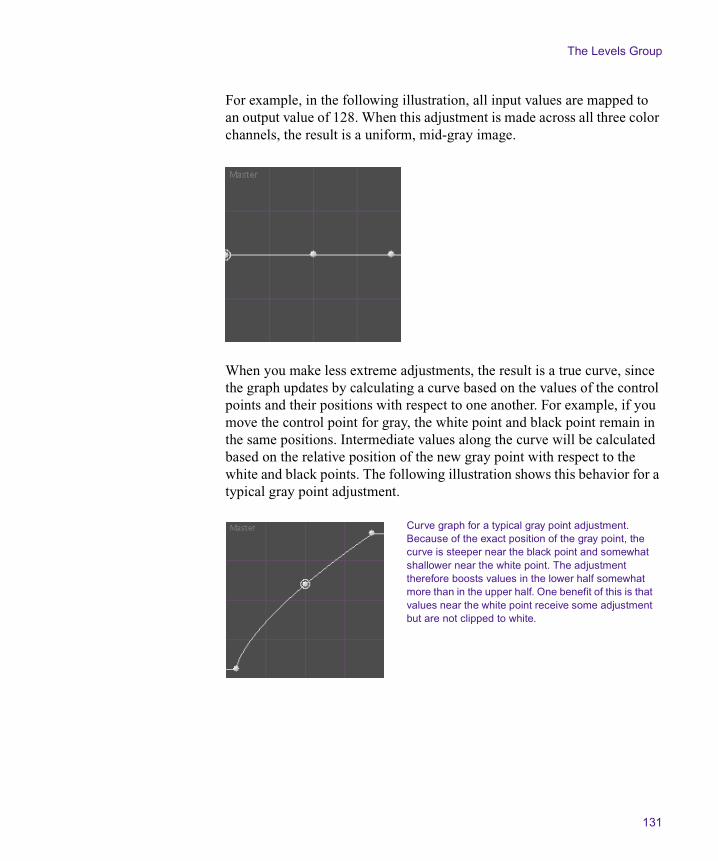
The Levels Group
131
For example, in the following illustration, all input values are mapped to an output value of 128. When this adjustment is made across all three color channels, the result is a uniform, mid-gray image.
When you make less extreme adjustments, the result is a true curve, since the graph updates by calculating a curve based on the values of the control points and their positions with respect to one another. For example, if you move the control point for gray, the white point and black point remain in the same positions. Intermediate values along the curve will be calculated based on the relative position of the new gray point with respect to the white and black points. The following illustration shows this behavior for a typical gray point adjustment.
Curve graph for a typical gray point adjustment. Because of the exact position of the gray point, the curve is steeper near the black point and somewhat shallower near the white point. The adjustment therefore boosts values in the lower half somewhat more than in the upper half. One benefit of this is that values near the white point receive some adjustment but are not clipped to white.

Chapter 3 Performing Color Corrections
132
Using the Curve Graph in the Levels Tab
You adjust the Curve graph in the Levels tab by clicking one or more of the three control points and dragging it to a new position.
To adjust a control point:
t Click a control point, and drag it to a new position.
When you click a control point, a circle appears around it to indicate that it is selected.
Working with the Composite and Luma Tabs
The Composite tab shows histograms that represent the levels in the composite image before and after correction. The Luma tab shows histograms that represent the luminance levels in the image before and after correction. They are useful for checking whether your color-corrected images are within the composite and luminance limits you need to meet and for adjusting levels to meet those limits, if necessary.
The Composite tab can display unit information in either IRE units or millivolts, depending on which option is selected in the Correction Mode Settings dialog box. The Luma tab can display unit information in a broader range of unit types. For more information, see “Customizing the Color Correction Tool” on page 58.
You can make only black point and white point adjustments in the Composite and Luma tabs. By adjusting these two points, if necessary, you can bring any values that exceed your composite or luminance limits back into an acceptable range.

The Levels Group
133
The following illustration shows the controls for the Composite histogram and Curve graph.
You can use the Composite and Luma tabs together with the Safe Color feature to ensure that your images remain within limits. If you set the Safe Colors feature to warn when composite and luminance limits are exceeded, parts of the image that exceed the limit appear orange in the histograms and you can use these warnings to guide your adjustments. If you set the Safe Colors feature to limit automatically when composite and luminance limits are exceeded, you can use the Composite and Luma tabs to bring most of the image within limits and let Safe Color limiting automatically clip occasional excessive values. For more information on the Safe Colors feature and on composite and luminance limits for broadcast, see Chapter 7.
Examples of Levels Adjustments
The following illustrations show some common levels adjustments. In the first example, white, black, and gray points are all adjusted to create a small but significant change in the amount of contrast available in the image. In the second example, a gray point adjustment alone greatly increases the amount of detail that can be seen.
n If you are reading a hardcopy version of this document, you will find it useful to view the color images in the Help or in the online version of this document on the online publications CD-ROM.
Two control points in Curve graphBlack and white points only on histogram
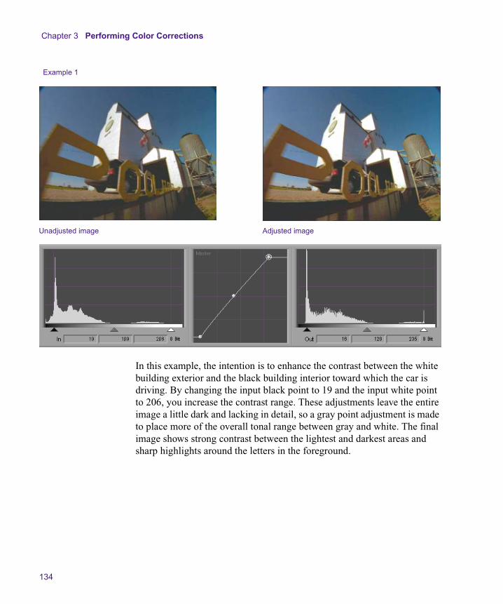
Chapter 3 Performing Color Corrections
134
In this example, the intention is to enhance the contrast between the white building exterior and the black building interior toward which the car is driving. By changing the input black point to 19 and the input white point to 206, you increase the contrast range. These adjustments leave the entire image a little dark and lacking in detail, so a gray point adjustment is made to place more of the overall tonal range between gray and white. The final image shows strong contrast between the lightest and darkest areas and sharp highlights around the letters in the foreground.
Example 1
Unadjusted image Adjusted image

The Levels Group
135
In this example, the gray point adjustment substantially increases the proportion of the tonal range that lies between gray and white. As a result, detail is greatly enhanced in the image, revealing such details as the lettering on the wall at the extreme right.
Example 2
Unadjusted image Adjusted image
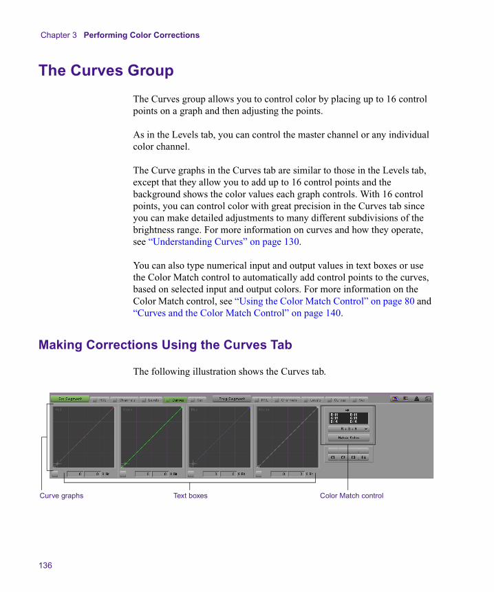
Chapter 3 Performing Color Corrections
136
The Curves Group
The Curves group allows you to control color by placing up to 16 control points on a graph and then adjusting the points.
As in the Levels tab, you can control the master channel or any individual color channel.
The Curve graphs in the Curves tab are similar to those in the Levels tab, except that they allow you to add up to 16 control points and the background shows the color values each graph controls. With 16 control points, you can control color with great precision in the Curves tab since you can make detailed adjustments to many different subdivisions of the brightness range. For more information on curves and how they operate, see “Understanding Curves” on page 130.
You can also type numerical input and output values in text boxes or use the Color Match control to automatically add control points to the curves, based on selected input and output colors. For more information on the Color Match control, see “Using the Color Match Control” on page 80 and “Curves and the Color Match Control” on page 140.
Making Corrections Using the Curves Tab
The following illustration shows the Curves tab.
Curve graphs Text boxes Color Match control

The Curves Group
137
To make corrections using the Curves tab:
1. If you have not already done so:
a. Move the position indicator to the segment you want to correct.
b. Select a relationship from the Source or Program tab.
c. Click the Curves tab for the side (Source or Program) in which you want to work.
n For more information on Source and Program sides and relationships, see “Understanding Source and Program Color Correction” on page 23 and “Working with the Source and Program Tabs” on page 47.
2. Adjust the curves until you are satisfied with the results.
For more information on adjusting curves, see “Adjusting Curves” on page 137.
Adjusting Curves
Adjusting Curve graphs in the Curves tab is similar to adjusting the three-point Curve graph in the Levels tab. In the Curves tab, however, you can set up to 16 total control points on a Curve graph.
To add a control point:
t Click the curve line in the graph at the point where you want the new point to appear.
A new control point appears with a circle around it to indicate that it is the active control point.
New control point
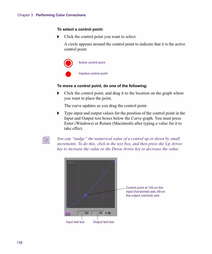
Chapter 3 Performing Color Corrections
138
To select a control point:
t Click the control point you want to select.
A circle appears around the control point to indicate that it is the active control point.
To move a control point, do one of the following:
t Click the control point, and drag it to the location on the graph where you want to place the point.
The curve updates as you drag the control point.
t Type input and output values for the position of the control point in the Input and Output text boxes below the Curve graph. You must press Enter (Windows) or Return (Macintosh) after typing a value for it to take effect.
n You can “nudge” the numerical value of a control up or down by small increments. To do this, click in the text box, and then press the Up Arrow key to increase the value or the Down Arrow key to decrease the value.
Active control point
Inactive control point
Input text box Output text box
Control point at 100 on the input (horizontal) axis, 69 on the output (vertical) axis
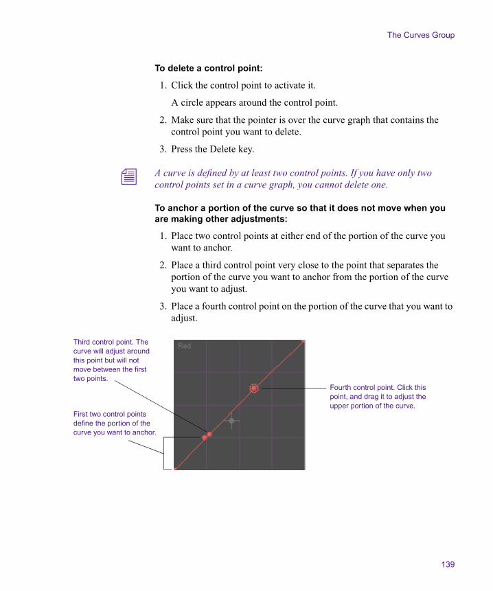
The Curves Group
139
To delete a control point:
1. Click the control point to activate it.
A circle appears around the control point.
2. Make sure that the pointer is over the curve graph that contains the control point you want to delete.
3. Press the Delete key.
n A curve is defined by at least two control points. If you have only two control points set in a curve graph, you cannot delete one.
To anchor a portion of the curve so that it does not move when you are making other adjustments:
1. Place two control points at either end of the portion of the curve you want to anchor.
2. Place a third control point very close to the point that separates the portion of the curve you want to anchor from the portion of the curve you want to adjust.
3. Place a fourth control point on the portion of the curve that you want to adjust.
Third control point. The curve will adjust around this point but will not move between the first two points.
First two control points define the portion of the curve you want to anchor.
Fourth control point. Click this point, and drag it to adjust the upper portion of the curve.

Chapter 3 Performing Color Corrections
140
When you drag the new control point to adjust the curve, the portion of the curve between the first two control points will not move.
Curves and the Color Match Control
When you use the Color Match control in the Curves tab, a gray crosshair marker appears in each appropriate Curve graph to mark the intersection of the input value as defined by the input color swatch in the Color Match control and the output value as defined by the output color swatch in the Color Match control.
When you click the Match Color button, the system adds new control points and updates the Curve graphs to reflect the color match. If you are not using NaturalMatch or if the Curve graphs have not received any previous adjustment, the new control points will appear at the location of the crosshair marker. If you are using NaturalMatch or if the Curve graphs have already received some adjustment, the system makes a more complex calculation to reflect the input saturation and luminance values or to take earlier Curve graph adjustments into account. In these cases, the new control points will not appear at the location of the crosshair marker.
Anchored portion of the curve
Adjusted portion of the curve

The Curves Group
141
The following illustrations show this behavior both before and after you click the Match Color button.
The crosshair marker on the Green Curve graph represents the values for Green in the color swatches — Input 131, Output 105. Since R+G+B is selected as the Match Type, similar crosshair markers appear on the Red and Blue Curve graphs.
When you click the Match Color button, the system creates a new control point and updates the curve to reflect the color match. In this illustration, NaturalMatch is selected and the calculation is not complicated by other control points, so the new control point is created at the exact location of the crosshair marker. The Green input and output values as shown in the color swatches now appear in the Input and Output text boxes below the graph.
Chapter 3 Performing Color Corrections
142
Examples of Curve Adjustments
The following illustrations show a series of simple adjustments made to an image using the Red curve in the Curves tab. By comparing the results of these adjustments, you will learn how curves can be used to control color across different parts of the brightness range.
n If you are reading a hardcopy version of this document, you will find it useful to view the color images in the Help or in the online version of this document on the online publications CD-ROM.
In each adjustment example, the new corrected image and the curve used to produce it are shown together with one other image from the series for the purpose of comparison.
n In each example, the color of the background behind the control point represents the color change to the image. In the first example, creating a curve through the darker cyan area causes reds to be reduced in the darker parts of the image. In the second example, creating a curve through the lighter cyan area causes reds to be reduced in the lighter areas of the image.

The Curves Group
143
Adjustment 1. Red is reduced primarily in the shadows range (the lower part of the curve). Notice how much of the red tone is lost from the background grass, the shirt, and the lower red signpost, which loses much of its detail. The higher red signpost is relatively less desaturated, however, and some of the reddish tinge is retained in the cloud highlights in the top right.
Uncorrected Image
Adjustment 1

Chapter 3 Performing Color Corrections
144
Adjustment 2. Red is reduced primarily in the highlights range (the upper part of the curve). The differences between this adjustment and adjustment 1 are most apparent in the lower signpost, which retains more redness and detail, and in the background, where the crop in the lower right retains more red tones, but the cloud highlights in the top right have lost their red tinge.
Adjustment 1
Adjustment 2
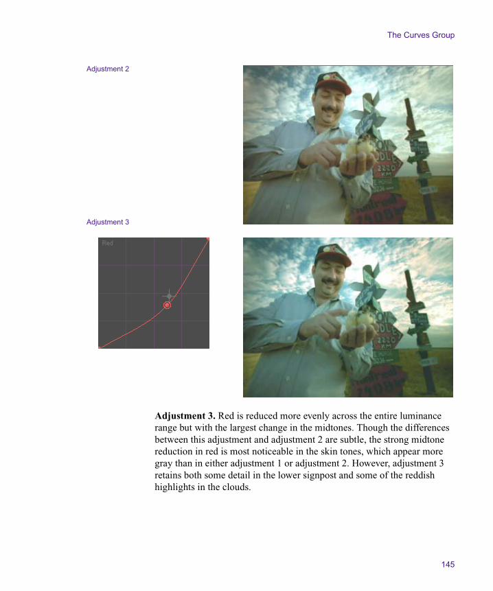
The Curves Group
145
Adjustment 3. Red is reduced more evenly across the entire luminance range but with the largest change in the midtones. Though the differences between this adjustment and adjustment 2 are subtle, the strong midtone reduction in red is most noticeable in the skin tones, which appear more gray than in either adjustment 1 or adjustment 2. However, adjustment 3 retains both some detail in the lower signpost and some of the reddish highlights in the clouds.
Adjustment 2
Adjustment 3
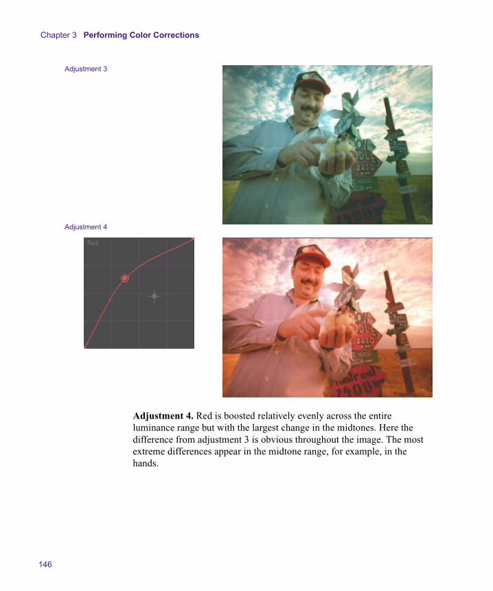
Chapter 3 Performing Color Corrections
146
Adjustment 4. Red is boosted relatively evenly across the entire luminance range but with the largest change in the midtones. Here the difference from adjustment 3 is obvious throughout the image. The most extreme differences appear in the midtone range, for example, in the hands.
Adjustment 3
Adjustment 4
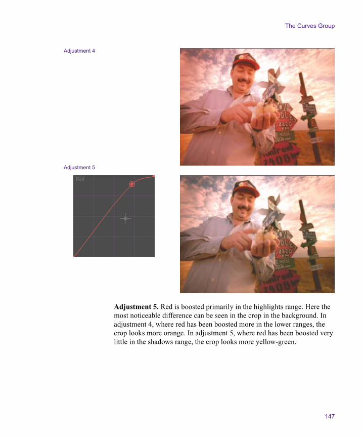
The Curves Group
147
Adjustment 5. Red is boosted primarily in the highlights range. Here the most noticeable difference can be seen in the crop in the background. In adjustment 4, where red has been boosted more in the lower ranges, the crop looks more orange. In adjustment 5, where red has been boosted very little in the shadows range, the crop looks more yellow-green.
Adjustment 4
Adjustment 5
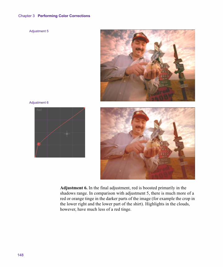
Chapter 3 Performing Color Corrections
148
Adjustment 6. In the final adjustment, red is boosted primarily in the shadows range. In comparison with adjustment 5, there is much more of a red or orange tinge in the darker parts of the image (for example the crop in the lower right and the lower part of the shirt). Highlights in the clouds, however, have much less of a red tinge.
Adjustment 5
Adjustment 6
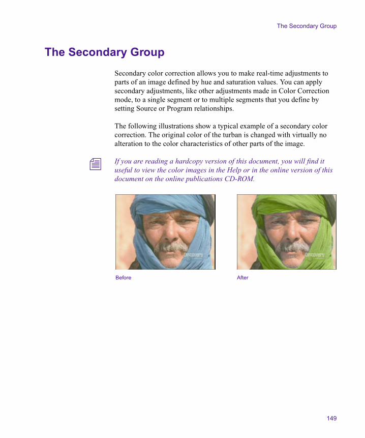
The Secondary Group
149
The Secondary Group
Secondary color correction allows you to make real-time adjustments to parts of an image defined by hue and saturation values. You can apply secondary adjustments, like other adjustments made in Color Correction mode, to a single segment or to multiple segments that you define by setting Source or Program relationships.
The following illustrations show a typical example of a secondary color correction. The original color of the turban is changed with virtually no alteration to the color characteristics of other parts of the image.
n If you are reading a hardcopy version of this document, you will find it useful to view the color images in the Help or in the online version of this document on the online publications CD-ROM.
Before After

Chapter 3 Performing Color Corrections
150
Understanding Secondary Color Correction
The Secondary group provides controls for making hue and saturation adjustments to as many as 12 distinct parts of the full color range in an image.
Secondary color correction is most useful for images in which the following two circumstances apply:
• You want to change the color characteristics of some parts of the image without altering the rest of the image in any way.
• The parts of the image that you want to change are characterized by hue and saturation values that are absent or nearly absent from the rest of the image.
For example, you might be correcting a shot of a person wearing a bright yellow scarf. After earlier stages of color correction, you are pleased with the image in general, but the scarf remains too bright. You can use secondary color correction to select the bright yellow of the scarf and then make an adjustment to alter the yellow color. The system applies that adjustment to only the bright yellow pixels in the image. As long as no other parts of the image are bright yellow, your correction changes the color of the scarf alone, preserving the rest of the image untouched.
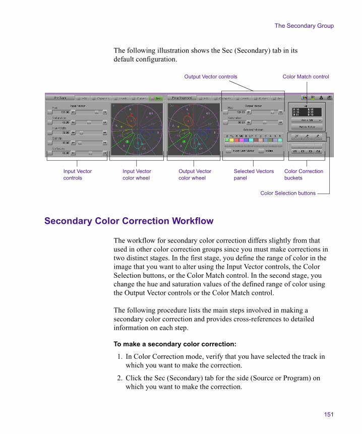
The Secondary Group
151
The following illustration shows the Sec (Secondary) tab in its default configuration.
Secondary Color Correction Workflow
The workflow for secondary color correction differs slightly from that used in other color correction groups since you must make corrections in two distinct stages. In the first stage, you define the range of color in the image that you want to alter using the Input Vector controls, the Color Selection buttons, or the Color Match control. In the second stage, you change the hue and saturation values of the defined range of color using the Output Vector controls or the Color Match control.
The following procedure lists the main steps involved in making a secondary color correction and provides cross-references to detailed information on each step.
To make a secondary color correction:
1. In Color Correction mode, verify that you have selected the track in which you want to make the correction.
2. Click the Sec (Secondary) tab for the side (Source or Program) on which you want to make the correction.
Input Vector controls
Input Vector color wheel
Output Vector color wheel
Selected Vectors panel
Output Vector controls Color Match control
Color Correction buckets
Color Selection buttons

Chapter 3 Performing Color Corrections
152
3. Select a relationship to control the scope of the correction.
For more information, see “Working with the Source and Program Tabs” on page 47.
4. Move the position indicator to the segment you want to correct.
5. Select a predefined color vector as a starting point for defining the color range you want to correct.
For more information, see “Understanding Secondary Color Correction Vectors” on page 153 and “Selecting Vectors” on page 160.
6. Adjust the input values of the vector until it corresponds to the color range you want to correct.
For more information, see “Adjusting Input Vector Values” on page 162.
7. (Option) As an alternative to steps 5 and 6, use the Color Selection buttons to select, enable, and adjust an input color vector based on colors that you sample from the image. For more information, see “Using the Color Selection Buttons” on page 167.
8. Correct the color range you have defined by adjusting the output values of the vector.
For more information, see “Adjusting Output Vector Values” on page 173.
n You can also use the Color Match control to quickly make a correction based on input and output color values that you select, and then fine-tune the correction using Input and Output Vector controls. For more information, see “Using the Color Match Control for Secondary Corrections” on page 174.
The Secondary Group
153
Understanding Secondary Color Correction Vectors
Secondary color correction is based on the concept of color vectors. A vector is a subset of the full color range in an image. When you work in the Secondary group, you select a predefined vector as a starting point, adjust the vector so that it represents the exact color range you want to correct, and then change the color characteristics of that vector.
Standard and Custom Vectors
The system provides twelve predefined color vectors. The first six, known as standard vectors, represent the following major colors: Green, Yellow, Red, Magenta, Blue, Cyan. The remaining six, known as custom vectors, represent other, more narrowly defined colors that are useful starting points for common corrections (for example, blues that can be easily customized to define the sky color in an image).
Vector Display in Color Wheels
The Secondary tab displays vectors graphically in color wheels similar to those used in the Hue Offsets tab of the HSL group. In these displays, the full wheel represents the complete range of possible hue and saturation values, and each vector appears as a distinct area within the wheel. For more information on the color wheels and how they represent hue and saturation values, see “Understanding the Hue Offsets Color Wheel” on page 99.
n If you are reading a hardcopy version of this document, you will find it useful to view the color images in the Help or in the online version of this document on the online publications CD-ROM.
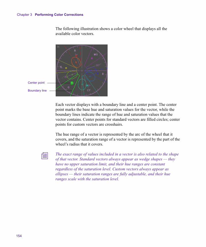
Chapter 3 Performing Color Corrections
154
The following illustration shows a color wheel that displays all the available color vectors.
Each vector displays with a boundary line and a center point. The center point marks the base hue and saturation values for the vector, while the boundary lines indicate the range of hue and saturation values that the vector contains. Center points for standard vectors are filled circles; center points for custom vectors are crosshairs.
The hue range of a vector is represented by the arc of the wheel that it covers, and the saturation range of a vector is represented by the part of the wheel’s radius that it covers.
n The exact range of values included in a vector is also related to the shape of that vector. Standard vectors always appear as wedge shapes — they have no upper saturation limit, and their hue ranges are constant regardless of the saturation level. Custom vectors always appear as ellipses — their saturation ranges are fully adjustable, and their hue ranges scale with the saturation level.
Center point
Boundary line
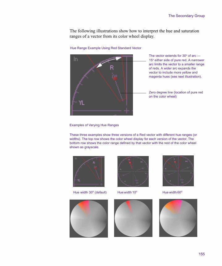
The Secondary Group
155
The following illustrations show how to interpret the hue and saturation ranges of a vector from its color wheel display.
Zero degree line (location of pure red on the color wheel)
The vector extends for 30o of arc — 15o either side of pure red. A narrowerarc limits the vector to a smaller rangeof reds. A wider arc expands the vector to include more yellow and magenta hues (see next illustration).
Hue Range Example Using Red Standard Vector
Examples of Varying Hue Ranges
These three examples show three versions of a Red vector with different hue ranges (or widths). The top row shows the color wheel display for each version of the vector. The bottom row shows the color range defined by that vector with the rest of the color wheel shown as grayscale.
Hue width 30o (default) Hue width 10o Hue width 60o
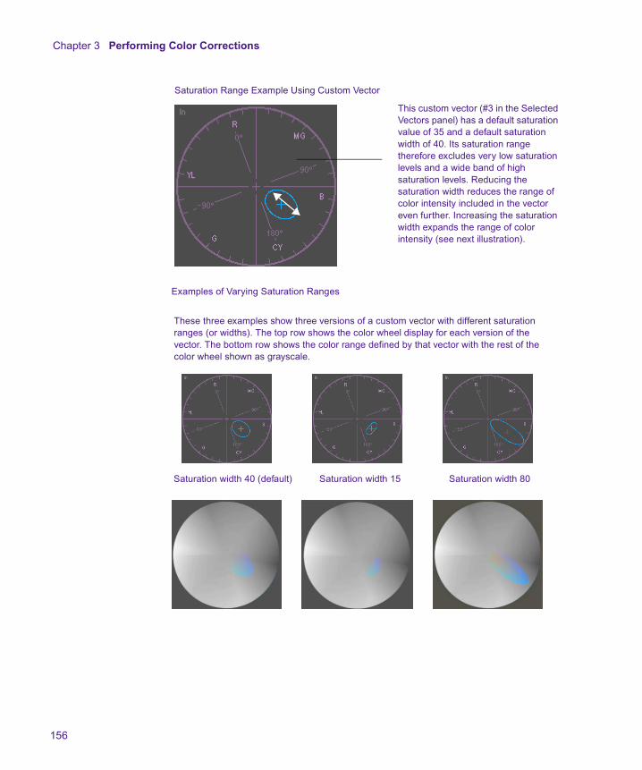
Chapter 3 Performing Color Corrections
156
Saturation Range Example Using Custom Vector
This custom vector (#3 in the Selected Vectors panel) has a default saturation value of 35 and a default saturation width of 40. Its saturation range therefore excludes very low saturation levels and a wide band of high saturation levels. Reducing the saturation width reduces the range of color intensity included in the vector even further. Increasing the saturation width expands the range of color intensity (see next illustration).
Examples of Varying Saturation Ranges
These three examples show three versions of a custom vector with different saturation ranges (or widths). The top row shows the color wheel display for each version of the vector. The bottom row shows the color range defined by that vector with the rest of the color wheel shown as grayscale.
Saturation width 40 (default) Saturation width 15 Saturation width 80
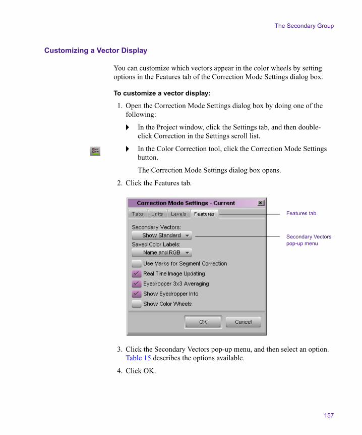
The Secondary Group
157
Customizing a Vector Display
You can customize which vectors appear in the color wheels by setting options in the Features tab of the Correction Mode Settings dialog box.
To customize a vector display:
1. Open the Correction Mode Settings dialog box by doing one of the following:
t In the Project window, click the Settings tab, and then double-click Correction in the Settings scroll list.
t In the Color Correction tool, click the Correction Mode Settings button.
The Correction Mode Settings dialog box opens.
2. Click the Features tab.
3. Click the Secondary Vectors pop-up menu, and then select an option. Table 15 describes the options available.
4. Click OK.
Features tab
Secondary Vectors pop-up menu

Chapter 3 Performing Color Corrections
158
Table 15 Secondary Color Correction Vector Display Options
Option Description Display in Color Wheels
Show All Shows all twelve vectors in the color wheels of the Secondary tab.
Show Standard Shows the six standard vectors (Green, Yellow, Red, Magenta, Blue, Cyan) in the color wheels of the Secondary tab. This setting also shows custom vectors that are enabled. This is the default setting.
Show Custom Shows the six custom (elliptical) vectors in the color wheels of the Secondary tab. This setting also shows standard vectors that are enabled.
Show Enabled Shows only those vectors that are currently enabled in the Selected Vectors panel. The illustration shows the Red standard vector and one custom vector.

The Secondary Group
159
Understanding the Selected Vectors Panel
The Selected Vectors panel provides a central location in the Secondary group tab for controls that allow you to select or enable individual vectors.
In addition, the Selected Vectors panel includes the following check boxes:
• Invert Last Vector. Checking this box inverts the effect of the enabled vector furthest to the right in the Selected Vectors panel. When you invert a vector, you apply the adjustment to all parts of the image except those parts defined by the vector. For more information, see “Inverting a Vector” on page 176.
• Isolate. Checking this box isolates the selected vector in the image by displaying all other parts of the image as grayscale.
You can use Isolate both as a preview feature and as an effect in its own right. While you are making a secondary color correction, you can select Isolate to see the extent of a vector more clearly. If you leave Isolate selected as part of a finished secondary color correction, you create a special secondary color correction that isolates one color range while displaying the rest of the image as grayscale. For more information, see “Isolating the Selected Vector” on page 170.
The following illustration shows the Selected Vectors panel with the Green vector selected.
n If you are reading a hardcopy version of this document, you will find it useful to view the color images in the Help or in the online version of this document on the online publications CD-ROM.
Vector names
Color swatches
Enable buttons
Standard vectors Custom vectors
Invert Last Vector check box Isolate check box

Chapter 3 Performing Color Corrections
160
The color swatches for each vector in the Selected Vectors panel update in real time to provide a visual indication of the defined color range for the vector. The following illustrations show this behavior for the Red vector color swatch.
Selecting Vectors
You must select a vector to make an adjustment. Any adjustments that you make using controls in the Secondary tab are made to the currently selected vector.
To select a vector, do one of the following:
t Click the center point of the vector in the color wheel.
t Click the vector’s color swatch in the Selected Vectors panel.
For more information, see “Understanding the Selected Vectors Panel” on page 159.
t Use the syringe to define an input vector.
The system automatically selects, enables, and adjusts the appropriate vector based on the colors you sample. For more information, see “Using the Color Selection Buttons” on page 167.
A white box appears around the color swatch for the selected vector in the Selected Vectors panel, and the selected vector appears highlighted in the color wheels.
Default Red vector color swatch
Red vector color swatch after hue is
adjusted to +20o
The Secondary Group
161
Enabling and Disabling Vectors
You can enable and disable vectors in any combination using Enable buttons. Enable buttons for vectors function in the same way as Enable buttons elsewhere in the Color Correction tool. For more information on Enable buttons, see “Working with the Enable Buttons” on page 55.
To enable or disable a vector, do one of the following:
t Click the vector’s Enable button in the Selected Vectors panel.
t Use the syringe to define an input vector.
The system automatically selects, enables, and adjusts the appropriate vector based on the colors you sample. For more information, see “Using the Color Selection Buttons” on page 167.
Enable buttons are pink when the associated vector is enabled and gray when the associated vector is disabled.
Resetting Vectors
You can use a vector’s Enable button to quickly reset the vector to its default values. For more information on Enable buttons, see “Working with the Enable Buttons” on page 55.
To reset a vector:
t Alt+click (Windows) or Option+click (Macintosh) the vector’s Enable button in the Selected Vectors panel.
The system resets the vector to its predefined values.

Chapter 3 Performing Color Corrections
162
Adjusting Input Vector Values
Once you have selected a predefined vector as a starting point for a secondary correction, you adjust that vector so that it represents as accurately as possible the specific color range that you want to correct.
Secondary color correction allows you to make adjustments using several different kinds of controls. You can also use the Isolate check box to select a preview display that makes it easy to see what parts of an image are included in a vector.
To adjust an input vector:
1. Select the vector you want to adjust.
For more information, see “Selecting Vectors” on page 160.
2. Adjust the vector by doing one or more of the following:
t Manipulate the vector directly in the Input color wheel. For more information, see “Repositioning Vectors in the Color Wheel” on page 163.
t Adjust the input sliders. For more information, see “Using the Input Vector Sliders” on page 163.
t Select colors from the image using the syringe and eyedroppers. For more information, see “Using the Color Selection Buttons” on page 167.
3. As you make your adjustments, use the Isolate feature to verify what parts of the image are currently defined by the vector. For more information, see “Isolating the Selected Vector” on page 170.
The Secondary Group
163
Repositioning Vectors in the Color Wheel
You can reposition a vector in the color wheel by dragging its center point. This changes the hue and saturation values of the vector.
To reposition a vector in a color wheel:
1. Move the pointer over the center point of the vector.
The pointer changes to a hand.
2. Click the mouse button, and drag the center point of the vector to a new location in the color wheel.
As you drag the center point around in the color wheel, the Hue and Saturation sliders update to show the current hue and saturation values, and the vector’s color swatch updates in the Selected Vectors panel to show the currently selected color.
3. Release the mouse button when you are satisfied with the hue and saturation values.
Using the Input Vector Sliders
You can change the values of a vector by adjusting the Input Vector sliders. These sliders work in exactly the same way as other sliders in the Color Correction tool, for example, those in the HSL group. For more information, see “Using the HSL Sliders” on page 94.

Chapter 3 Performing Color Corrections
164
Table 16 describes the individual sliders available for input vectors.
Table 16 Input Vector Sliders
Control Description
Hue Shifts the hue value for the center point of the vector around the color wheel. On the default Degree unit scale, 0 (the center point of the slider) represents red and –180 or 180 (the end points of the slider) represents cyan.
Saturation Shifts the saturation value for the center point of the vector between the center and the outer edge of the color wheel. On the default Percent unit scale, 0 represents no saturation (the center of the wheel) and 100 represents full saturation (the outer edge of the wheel).
Hue Width Sets the hue range of the vector. On the default Degree unit scale, values represent the number of degrees of arc that the vector covers on the color wheel, with the Hue value being the midpoint of the arc. For standard vectors, values range from 0 to 180; for custom vectors, values range from 0 to 100.
Saturation Minimum (standard vectors)
Saturation Width (custom vectors)
For standard vectors, sets the minimum saturation value for the vector. Pixels in the image below the saturation minimum are not included in the vector even if their hue value is within the vector’s hue width.
For custom vectors, sets the saturation range of the vector. On the default Percent scale, values represent the saturation range as a percentage of the maximum saturation width. For example, a vector with Saturation Width 40 extends across 40% of the full saturation range. Pixels in the image outside this saturation range are not included in the vector even if their hue value is within the vector’s hue width.
The Secondary Group
165
Examples of Softness Adjustments
Softness is an important control for fine-tuning the effect of a secondary correction on an image. You can control the appearance of the transitional areas between a corrected part of the image and the rest of the image. You can also quickly compensate for inaccuracies in the input vector definition by expanding or contracting the color range over which the correction has an effect.
The following illustrations show the effect of a range of Softness adjustments on a test image.
n If you are reading a hardcopy version of this document, you will find it useful to view the color images in the Help or in the online version of this document on the online publications CD-ROM.
Softness Sets a softness value for the vector. Values range from –255 to 255.
Positive values blend the corrected color into areas of the image beyond the limits of the defined input vector. The higher the value, the further into adjacent color values the blend extends.
Negative values blend the uncorrected color into parts of the area defined by the input vector. The higher the value, the more of the uncorrected color is retained in the input vector area.
When Softness is set to 0, the correction has a hard edge at the limit of the defined input vector. The default Softness setting of 30 creates a softened edge without extending the corrected color significantly outside the defined input vector.
For illustrations of the effect of various Softness settings, see “Examples of Softness Adjustments” on page 165.
Table 16 Input Vector Sliders (Continued)
Control Description
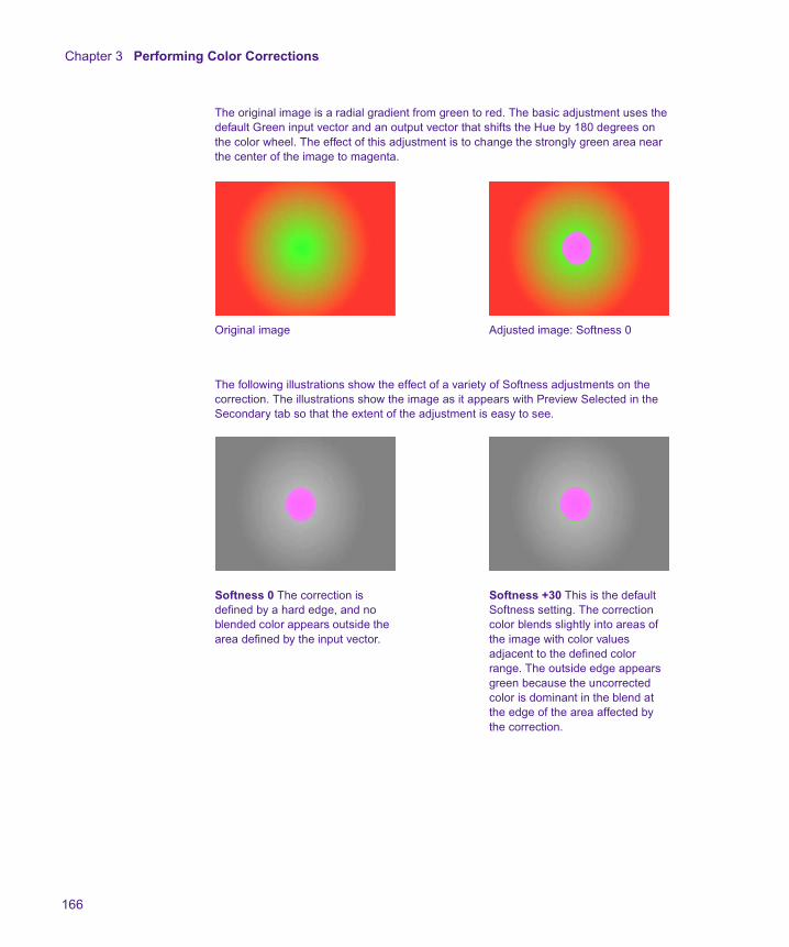
Chapter 3 Performing Color Corrections
166
The original image is a radial gradient from green to red. The basic adjustment uses the default Green input vector and an output vector that shifts the Hue by 180 degrees on the color wheel. The effect of this adjustment is to change the strongly green area near the center of the image to magenta.
Original image Adjusted image: Softness 0
The following illustrations show the effect of a variety of Softness adjustments on the correction. The illustrations show the image as it appears with Preview Selected in the Secondary tab so that the extent of the adjustment is easy to see.
Softness 0 The correction is defined by a hard edge, and no blended color appears outside the area defined by the input vector.
Softness +30 This is the default Softness setting. The correction color blends slightly into areas of the image with color values adjacent to the defined color range. The outside edge appears green because the uncorrected color is dominant in the blend at the edge of the area affected by the correction.
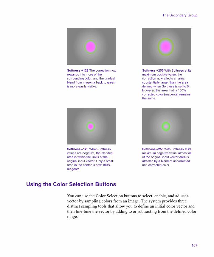
The Secondary Group
167
Using the Color Selection Buttons
You can use the Color Selection buttons to select, enable, and adjust a vector by sampling colors from an image. The system provides three distinct sampling tools that allow you to define an initial color vector and then fine-tune the vector by adding to or subtracting from the defined color range.
Softness +128 The correction now expands into more of the surrounding color, and the gradual blend from magenta back to green is more easily visible.
Softness +255 With Softness at its maximum positive value, the correction now affects an area substantially larger than the area defined when Softness is set to 0. However, the area that is 100% corrected color (magenta) remains the same.
Softness –128 When Softness values are negative, the blended area is within the limits of the original input vector. Only a small area in the center is now 100% magenta.
Softness –255 With Softness at its maximum negative value, almost all of the original input vector area is affected by a blend of uncorrected and corrected color.

Chapter 3 Performing Color Corrections
168
You can use the Color Selection buttons together with the Color Match control to quickly perform a complete secondary color correction. For more information, see “Using the Color Match Control for Secondary Corrections” on page 174.
You can also use the Color Selection buttons to refine the definition of an existing vector by sampling colors within or adjacent to that vector.
The following illustration shows the Color Selection buttons.
Defining a Vector with the Syringe
To define a vector using the syringe:
1. Click the Syringe button to highlight it.
2. Move the pointer over the image in the active monitor.
The pointer changes to a syringe.
3. Move the tip of the syringe over the area of color you want to sample in the image.
4. Press and hold the mouse button, and drag the tip of the syringe over the area of color you want to sample.
The system samples every color value that the tip of the syringe passes over. The input color swatch in the Color Match control updates as you drag the syringe to show the most recently sampled color.
n Try to cover the area that you want to sample as fully as possible, but take care not to stray outside that area. Remember that you can make further refinements to the vector after completing the initial selection.
Syringe button
Add to Selection button
Subtract from Selection button
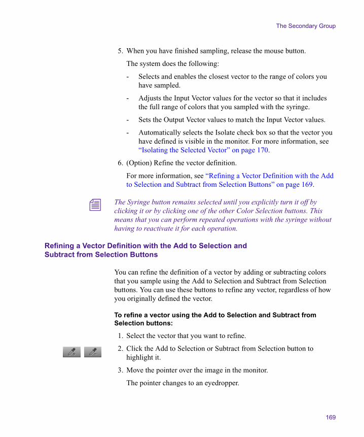
The Secondary Group
169
5. When you have finished sampling, release the mouse button.
The system does the following:
- Selects and enables the closest vector to the range of colors you have sampled.
- Adjusts the Input Vector values for the vector so that it includes the full range of colors that you sampled with the syringe.
- Sets the Output Vector values to match the Input Vector values.
- Automatically selects the Isolate check box so that the vector you have defined is visible in the monitor. For more information, see “Isolating the Selected Vector” on page 170.
6. (Option) Refine the vector definition.
For more information, see “Refining a Vector Definition with the Add to Selection and Subtract from Selection Buttons” on page 169.
n The Syringe button remains selected until you explicitly turn it off by clicking it or by clicking one of the other Color Selection buttons. This means that you can perform repeated operations with the syringe without having to reactivate it for each operation.
Refining a Vector Definition with the Add to Selection and Subtract from Selection Buttons
You can refine the definition of a vector by adding or subtracting colors that you sample using the Add to Selection and Subtract from Selection buttons. You can use these buttons to refine any vector, regardless of how you originally defined the vector.
To refine a vector using the Add to Selection and Subtract from Selection buttons:
1. Select the vector that you want to refine.
2. Click the Add to Selection or Subtract from Selection button to highlight it.
3. Move the pointer over the image in the monitor.
The pointer changes to an eyedropper.

Chapter 3 Performing Color Corrections
170
4. Move the tip of the eyedropper over the color you want to add to or subtract from the vector, and then click the mouse button.
The system updates the vector to include or exclude the color you have selected.
n The Add to Selection or Subtract from Selection button remains selected until you explicitly deselect it by clicking it or by clicking one of the other Color Selection buttons. This means that you can perform repeated operations with the eyedropper without having to reselect it for each operation.
n The Undo command works with eyedropper color selections. If you select too much color with the Add to Selection eyedropper or subtract too much with the Subtract from Selection eyedropper, select Edit > Undo or press Ctrl+Z (Windows) or k+Z (Macintosh) to have the system delete the effect of that selection on the vector.
n When the system calculates revised vector areas based on selections made with the Add to Selection and Subtract from Selection eyedroppers, it is constrained by the geometric limits of the vector (wedge-shape for standard vectors and ellipse for custom vectors). As a result, you might include or exclude more colors than you expect. In general, the Color Selection buttons are excellent tools for quickly adjusting a vector to approximately the area you require. However, you might still need to fine-tune the vector using the sliders to achieve a precise match with the color range you want to correct.
Isolating the Selected Vector
You can isolate the selected vector in an image. The system displays those parts of the image that fall within the selected vector in color, with the rest of the image in grayscale. This makes it easy to see which parts of an image are included in a selected vector while you are making corrections.
You can choose to use Isolate only as a preview feature that allows you to see the extent of vectors clearly. In this case, you must deselect Isolate when you have finished making the correction. Alternatively, you can use

The Secondary Group
171
Isolate as a special Color Correction effect that isolates parts of an image in color while displaying the rest of the image in grayscale. In this case, you leave Isolate selected when you have finished making the correction.
To isolate the selected vector:
1. Make sure that the position indicator is in the segment that you want to isolate.
2. Click Isolate in the Selected Vectors panel of the Secondary tab.
The active monitor changes to isolate the selected vector.
3. Make input and output adjustments to the vector until you are satisfied with the look of the correction.
4. Do one of the following:
t To leave the areas of the image outside the vector grayscale, leave Isolate selected.
t To return the image to a full-color display, click the Isolate check box to deselect it.
n Isolate shows the effect of any output adjustment you have made to the vector. If you have made output adjustments and want to see a preview that shows only the input color range, disable the Output Vector Hue and Saturation sliders by clicking their Enable buttons.
The following illustration shows a typical image and its appearance when Isolate is selected. For more illustrated examples of the effect of isolating a vector, see “Examples of Inverted and Isolated Images” on page 177.
n If you are reading a hardcopy version of this document, you will find it useful to view the color images in the Help or in the online version of this document on the online publications CD-ROM.

Chapter 3 Performing Color Corrections
172
Original image in full color
Corrected image with Isolate selected. The preview shows the effect of an adjustment that changes the pale blue robe to match the green color of the shoes in the top left corner of the original image. Areas of the image not affected by the correction display as grayscale. The preview allows you to see which additional areas of the image are affected by the adjustment and confirm which areas are not — for example, the blue jacket in the bottom right.
Corrected image in full color. The correction has completely changed the color of the robe. A few other small areas of the image have also been changed by the correction, but most of the image retains its original color.
The Secondary Group
173
Adjusting Output Vector Values
Once you have an input vector defined correctly, the final step in the secondary color correction process is to adjust the output hue and saturation values for the vector to change the color characteristics.
Because you have already defined the extent of the vector using input adjustments, only hue and saturation values are adjustable for output. To change the color characteristics for that vector, you only need to define a new combination of hue and saturation values.
n You might make an output vector adjustment that causes the saturation levels in an image to exceed the RGB Gamut limits that you have set in the Safe Color Settings dialog box. Depending on the current settings in the Safe Color Settings dialog box, the system might ignore the excess value, display a warning, or automatically limit the color. For more information, see “Safe Color Warnings in the Secondary Group Tab” on page 253 and the more general information on safe colors in Chapter 7.
To adjust output vector values:
1. Select the vector you want to adjust.
2. Adjust the output vector values by doing one of the following:
t Manipulate the vector directly in the Output color wheel. For more information, see “Repositioning Vectors in the Color Wheel” on page 163.
t Adjust the output sliders. The Output Vector Hue and Saturation sliders are identical to their Input Vector equivalents. For more information, see “Using the Input Vector Sliders” on page 163.
As you adjust the output values, the active monitor updates to show the effect of the correction on your image. If Isolate is selected, the monitor will show the corrected areas of the image in color and the unaffected areas of the image as grayscale.

Chapter 3 Performing Color Corrections
174
3. Do one of the following:
t To have the areas of the image outside the vector continue to display as grayscale, make sure that Isolate is selected.
t To have the image appear as a full-color display, make sure that Isolate is deselected.
Using the Color Match Control for Secondary Corrections
You can use the Color Match control to make secondary color corrections based on color values that you sample from images or select from the Windows Color dialog box or the Macintosh Color Picker. If necessary, you can make further refinements to the input and output vectors after the color match to achieve the precise correction that you want.
You can use the Color Match control together with the syringe to perform a secondary color correction based on a range of sampled color values. In most circumstances, this is the preferred method for achieving a good correction when the hue and saturation values of the area you want to correct are somewhat varied. This method also shows the selected vector before you complete the match, making it easier to verify that you have a well-defined input vector.
You can also use the Color Match control to make a secondary color correction with the same basic methods that you use to make Color Match corrections in the other Color Correction tabs. In this case, the system applies the match to a predefined range of colors centered on the single color value that you sample, and you cannot see the input vector until the color match is completed. Though generally less precise and less controllable than the first method, this technique might produce acceptable results quickly if you need to correct an area of uniform color.
The Secondary Group
175
Making a Secondary Correction with the Color Match Control and the Syringe
To make a secondary color correction using the Color Match control and the syringe:
1. Select, enable, and define the input vector using the syringe.
For more information, see “Defining a Vector with the Syringe” on page 168.
n As part of the vector definition process, the system automatically selects Isolate.
2. Select the output color using the standard Color Match eyedropper. For more information, see “Making a Correction with the Color Match Control” on page 81.
3. Click the Match Type button, and select a Match Type to determine the exact nature of the match the system makes.
For more information on the options available in the Secondary group, see “Selecting Match Type Options” on page 83.
4. Click the Match Color button to make the correction.
The system adjusts the output values for that vector, deselects Isolate, and displays the corrected image in the monitor that contains the current segment.
5. (Option) Make further adjustments to the vectors using the Input Vector and Output Vector sliders until you are satisfied with the correction.
Making a Secondary Color Correction with the Color Match Control Only
To make a secondary color correction with the Color Match control only:
1. Select the input color using the standard Color Match eyedropper. For more information, see “Making a Correction with the Color Match Control” on page 81.
2. Select the output color using the standard Color Match eyedropper.
3. Click the Match Type button, and select a Match Type to determine the exact nature of the match the system makes.

Chapter 3 Performing Color Corrections
176
For more information on the match types available in the Secondary group, see “Selecting Match Type Options” on page 83.
4. Click the Match Color button to make the correction.
The system selects and enables a vector, adjusts the input and output values for that vector based on the sampled colors, and displays the corrected image in the monitor that contains the current segment.
5. (Option) Make further adjustments to the vectors using the Input Vector and Output Vector sliders until you are satisfied with the correction.
Inverting a Vector
You can invert a vector to apply a correction to every part of the image except for the area defined by the vector. The most common use of this technique is to isolate an object in its original color while altering the color of every other part of the image. For example, you might want to partially desaturate most of the image while retaining full color in the areas defined by the vector.
For illustrated examples of the use of the Isolate and Invert Last Vector features, see “Examples of Inverted and Isolated Images” on page 177.
To invert a vector:
1. Select the vector, and make input adjustments to it using standard methods.
2. Click Invert Last Vector in the Selected Vectors panel.
The system inverts the vector, selecting all parts of the image not defined within the vector. If you are working with Isolate selected, the display updates to show the area defined by the vector as grayscale and the rest of the image in color.
3. Adjust the output hue and saturation values for the vector.
4. Make sure that the Isolate check box is selected or deselected as necessary to produce the final effect that you want. For more information, see “Isolating the Selected Vector” on page 170.

The Secondary Group
177
n Invert Last Vector can invert only one vector in each correction, and the vector that is inverted is always the enabled vector furthest to the right in the Selected Vectors panel. In the common case of using Invert Last Vector to isolate one object in color, the vector that you invert is likely to be the only vector you need to adjust. If you do use Invert Last Vector in a segment where you make adjustments to multiple vectors, make sure that the inversion applies to the vector you want by making that vector the enabled vector furthest to the right in the Selected Vectors panel.
Examples of Inverted and Isolated Images
The following illustrations show the effects of Isolate and Invert Last Vector on a typical image. Using these two features alone or in combination, you can achieve a wide range of special Color Correction effects in which one area of the image stands out from the rest.
n If you are reading a hardcopy version of this document, you will find it useful to view the color images in the Help or in the online version of this document on the online publications CD-ROM.
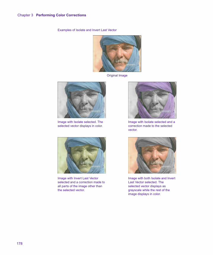
Chapter 3 Performing Color Corrections
178
Original Image
Image with Isolate selected. The selected vector displays in color.
Image with Isolate selected and a correction made to the selected vector.
Examples of Isolate and Invert Last Vector
Image with Invert Last Vector selected and a correction made to all parts of the image other than the selected vector.
Image with both Isolate and Invert Last Vector selected. The selected vector displays as grayscale while the rest of the image displays in color.

The Secondary Group
179
Understanding How Multiple Vectors Interact
If you make corrections to more than one vector in the Secondary group, those corrections are applied cumulatively to the image when it plays back. The order of application moves from left to right across the Selected Vectors panel.
If the color ranges of vectors overlap, the final result in the image is the cumulative result of all the corrections for the overlapping vectors. For example, if you use the Green vector to change a green object in the image to yellow, and then adjust the Yellow vector so yellow objects become red, your original green object is red in the final image.
Playback Considerations for Secondary Color Correction
When you use secondary color correction in combination with some effects that are normally real time, the Symphony system cannot play both the effect and the color correction in real time. In particular, the system cannot play a secondary color correction in real time along with a 3D effect, and cannot play any two-stream effects (such as a transition) in real time when both streams have secondary color corrections.
Secondary color correction therefore differs from primary color correction, which will always play in real time when combined with real-time effects.
Playing Secondary Color Corrections and 3D Effects
Because secondary color corrections and 3D effects use some of the same hardware components for processing, the Symphony system cannot play both a secondary color correction and a 3D effect in real time. You must render the 3D effect to achieve successful playback.
Until you render the 3D effect, the system will play the 3D effect correctly in real time but will not play the secondary color correction.
Chapter 3 Performing Color Corrections
180
When you preview a clip by stepping through one frame or field at a time, the system will update to show the effect of both the secondary color correction and the 3D effect on each field or frame.
If you submit a segment that contains both a secondary color correction and a 3D effect for analysis by ExpertRender™, the ExpertRender feature will identify the 3D effect for rendering.
Playing Secondary Color Corrections and Two-Stream Effects
Because Symphony can process only one secondary color correction at a time, it cannot play a two-stream effect in real time if both effect streams have secondary color correction. You must render the effect to achieve successful playback.
For example, the system cannot play any transition effect in real time when both the incoming and the outgoing clips have secondary color correction. Similarly, the system cannot play a Picture-in-Picture effect in real time if both the foreground and background images have secondary color correction.
Until you render the effect in these situations, the system either will play the effect without the secondary color corrections or will play a transition as a cut and play the secondary color corrections successfully.
When you preview a clip by stepping through one frame or field at a time, the system will update to show the effect of both the secondary color corrections and the two-stream effect on each field or frame.
If you submit a segment that contains secondary color corrections in combination with a two-stream effect for analysis by ExpertRender, the ExpertRender feature will identify the effect for rendering.
Working with the Waveform Monitors and Vectorscope Monitor
181
Working with the Waveform Monitors and Vectorscope Monitor
The waveform and vectorscope commands in the Source menu configure the monitor to graphically display color information about your sequence. The system displays the information for the currently active monitor.
A waveform indicates the brightness of the image. The higher the green trace goes on the scale, the brighter that part of the image is.
Waveform monitors display all the information for the current field or frame overlaid in the waveform. That is, each left-to-right trace in the waveform represents one scan line. If you see a bright object on the left side of the image, you will see its peak on the left side of the waveform. A bright object in the top left of the image produces the same waveform if it is in the bottom left of the image.
To display a Waveform monitor or a Vectorscope monitor:
1. Click in the monitor for which you want to display color information.
The monitor becomes the active monitor.
2. In one of the other monitors, click the Source menu and select a waveform or vectorscope command.
The monitor displays the selected waveform or vectorscope information.
For more information, see “Using the Waveform and Vectorscope Information” on page 190.
n If you are reading a hardcopy version of this document, you will find it useful to view the color images in the Help or in the online version of this document on the online publications CD-ROM.

Chapter 3 Performing Color Corrections
182
Table 17 describes each command.
Table 17 Waveform and Vectorscope Commands
Command Description
Quad Display Displays the following waveform and vectorscope information in a single monitor (clockwise from the top left corner):
• YC Waveform
• Vectorscope
• RGB Histogram
• RGB Parade
For information on each display, see its individual entry in this table.
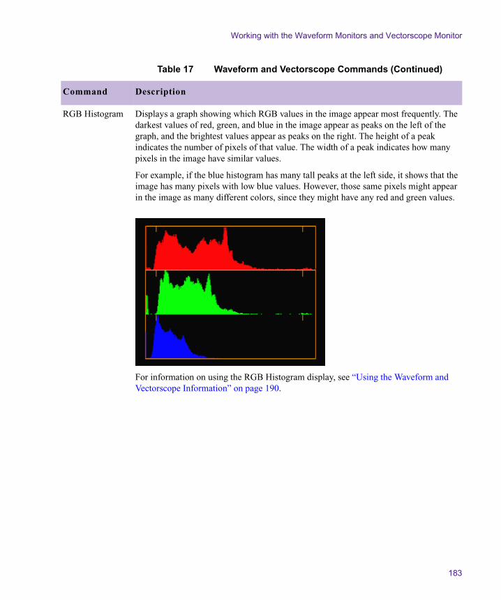
Working with the Waveform Monitors and Vectorscope Monitor
183
RGB Histogram Displays a graph showing which RGB values in the image appear most frequently. The darkest values of red, green, and blue in the image appear as peaks on the left of the graph, and the brightest values appear as peaks on the right. The height of a peak indicates the number of pixels of that value. The width of a peak indicates how many pixels in the image have similar values.
For example, if the blue histogram has many tall peaks at the left side, it shows that the image has many pixels with low blue values. However, those same pixels might appear in the image as many different colors, since they might have any red and green values.
For information on using the RGB Histogram display, see “Using the Waveform and Vectorscope Information” on page 190.
Table 17 Waveform and Vectorscope Commands (Continued)
Command Description

Chapter 3 Performing Color Corrections
184
RGB Parade Displays waveforms of the RGB (red, green, and blue) components side by side. Since video cameras capture in RGB, this display helps to show camera problems. It is also used for general reference to the three primary colors.
RGB signals are used together to create all other colors. A white area in the image appears as peaks in all three waveforms at the same relative location. A high red level does not mean a red image, unless the green and blue levels are low.
RGB Parade incorporates any safe color limits you have set. The system displays RGB values in white when the values fall outside the RGB Gamut limits. For more information on color limits, see “Safe Color Limits with Waveform and Vectorscope Information” on page 257.
For information on using the RGB Parade display, see “Using the Waveform and Vectorscope Information” on page 190.
Table 17 Waveform and Vectorscope Commands (Continued)
Command Description

Working with the Waveform Monitors and Vectorscope Monitor
185
Vectorscope Displays chroma information without luma information as a circular graph where the center represents no chroma and chroma increases as the trace moves away from the center.
All white, black, and gray parts of the image appear at the center. Areas with more saturation appear further out from the center. Images with an overall color cast produce a vectorscope trace that is generally off-center. Colors created by various positive and negative combinations of Cb and Cr appear around the circle.
Small squares mark the location of standard color bar vectors. Inner squares represent the proper values for 75% color bars, and outer squares represent 100% color bars.
For information on using the Vectorscope monitor, see “Using the Waveform and Vectorscope Information” on page 190.
Table 17 Waveform and Vectorscope Commands (Continued)
Command Description
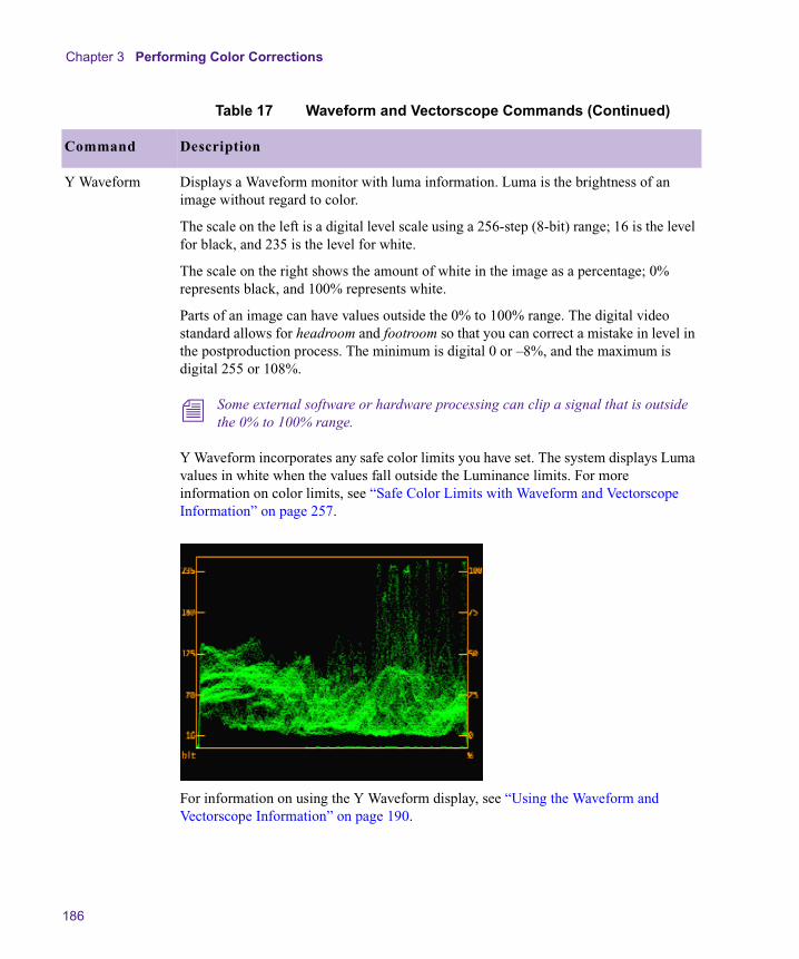
Chapter 3 Performing Color Corrections
186
Y Waveform Displays a Waveform monitor with luma information. Luma is the brightness of an image without regard to color.
The scale on the left is a digital level scale using a 256-step (8-bit) range; 16 is the level for black, and 235 is the level for white.
The scale on the right shows the amount of white in the image as a percentage; 0% represents black, and 100% represents white.
Parts of an image can have values outside the 0% to 100% range. The digital video standard allows for headroom and footroom so that you can correct a mistake in level in the postproduction process. The minimum is digital 0 or –8%, and the maximum is digital 255 or 108%.
n Some external software or hardware processing can clip a signal that is outside the 0% to 100% range.
Y Waveform incorporates any safe color limits you have set. The system displays Luma values in white when the values fall outside the Luminance limits. For more information on color limits, see “Safe Color Limits with Waveform and Vectorscope Information” on page 257.
For information on using the Y Waveform display, see “Using the Waveform and Vectorscope Information” on page 190.
Table 17 Waveform and Vectorscope Commands (Continued)
Command Description
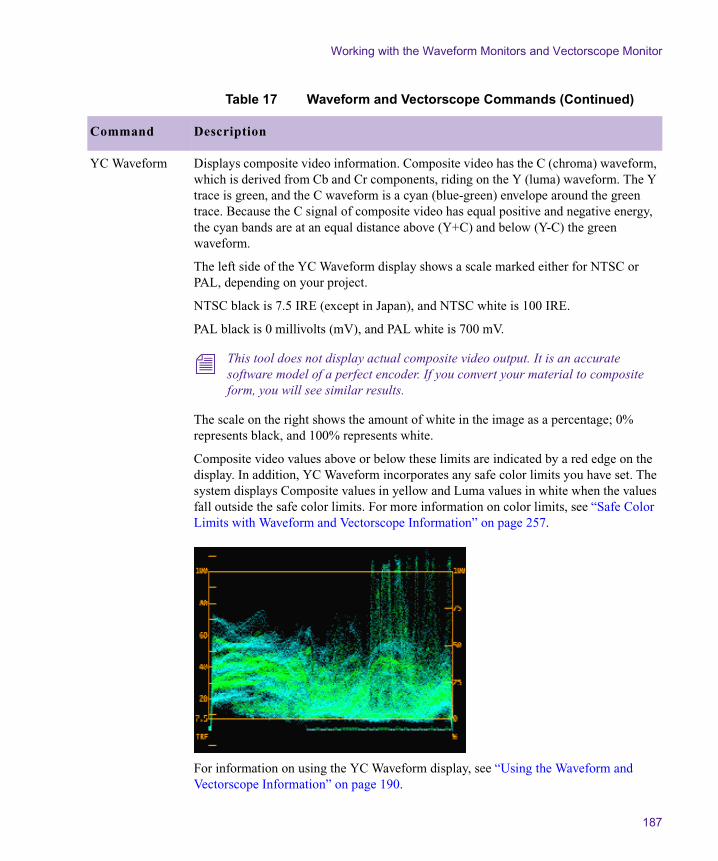
Working with the Waveform Monitors and Vectorscope Monitor
187
YC Waveform Displays composite video information. Composite video has the C (chroma) waveform, which is derived from Cb and Cr components, riding on the Y (luma) waveform. The Y trace is green, and the C waveform is a cyan (blue-green) envelope around the green trace. Because the C signal of composite video has equal positive and negative energy, the cyan bands are at an equal distance above (Y+C) and below (Y-C) the green waveform.
The left side of the YC Waveform display shows a scale marked either for NTSC or PAL, depending on your project.
NTSC black is 7.5 IRE (except in Japan), and NTSC white is 100 IRE.
PAL black is 0 millivolts (mV), and PAL white is 700 mV.
n This tool does not display actual composite video output. It is an accurate software model of a perfect encoder. If you convert your material to composite form, you will see similar results.
The scale on the right shows the amount of white in the image as a percentage; 0% represents black, and 100% represents white.
Composite video values above or below these limits are indicated by a red edge on the display. In addition, YC Waveform incorporates any safe color limits you have set. The system displays Composite values in yellow and Luma values in white when the values fall outside the safe color limits. For more information on color limits, see “Safe Color Limits with Waveform and Vectorscope Information” on page 257.
For information on using the YC Waveform display, see “Using the Waveform and Vectorscope Information” on page 190.
Table 17 Waveform and Vectorscope Commands (Continued)
Command Description
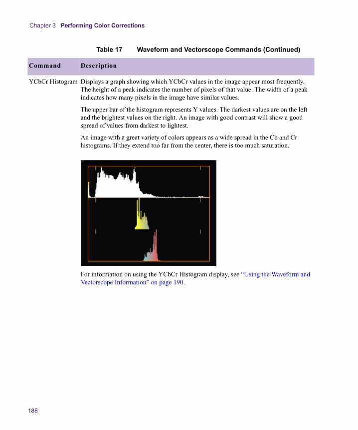
Chapter 3 Performing Color Corrections
188
YCbCr Histogram Displays a graph showing which YCbCr values in the image appear most frequently. The height of a peak indicates the number of pixels of that value. The width of a peak indicates how many pixels in the image have similar values.
The upper bar of the histogram represents Y values. The darkest values are on the left and the brightest values on the right. An image with good contrast will show a good spread of values from darkest to lightest.
An image with a great variety of colors appears as a wide spread in the Cb and Cr histograms. If they extend too far from the center, there is too much saturation.
For information on using the YCbCr Histogram display, see “Using the Waveform and Vectorscope Information” on page 190.
Table 17 Waveform and Vectorscope Commands (Continued)
Command Description

Working with the Waveform Monitors and Vectorscope Monitor
189
YCbCr Parade Displays waveforms of Y, Cb, and Cr side by side. The Y in YCbCr is the same luma shown in the Y Waveform display. In this display, the Y waveform is shown in white on the left side.
Cb and Cr are color difference signals that represent just the color information of a signal with the luma removed. Cb and Cr values can be negative or positive. For images that are black and white, Cb and Cr are zero. You would see a flat white line halfway up the two right bands. As they increase, Cb and Cr are shown in the colors representing those vectors. The more the values increase, the more saturated the colors used to display them. Positive Cb is represented by blue hues, and negative Cb is represented by yellow hues. Positive Cr is represented by red hues, and negative Cr is represented by cyan hues.
If the Cb or Cr waveforms are not centered, the cause might be a color cast to the image.
For information on using the YCbCr Parade display, see “Using the Waveform and Vectorscope Information” on page 190.
Table 17 Waveform and Vectorscope Commands (Continued)
Command Description

Chapter 3 Performing Color Corrections
190
Using the Waveform and Vectorscope Information
Some of the ways you can use the waveform and vectorscope information include:
• Align levels of sources using test patterns. If you capture some color bars from your source footage, you can measure them and set the color correction needed to restore the video levels to the way the program was created. Import the Test Patterns from the SupportingFiles folder of your Avid system to become familiar with the proper Waveform, Parade, and Vectorscope readings. Histograms are not as useful on test patterns. For example, with 75% color bars, the Y+C envelope for the yellow and cyan bars should match the 100% white level.
• Identify problems with source video. Typical problems include:
- Color levels too high or too low. See “Safe Color Limits with Waveform and Vectorscope Information” on page 257.
- Missing channels in YCbCr or RGB, indicating an equipment problem or a damaged cable.
- Clipping in YCbCr, RGB, or YC channels. The trace appears chopped at a certain level. If this appears at a level below the maximum, it occurred before the footage was captured.
- Images imported at the wrong level settings. If you import images at RGB levels of 0–255 that you should have imported at 601 levels of 16–235, the images will lack contrast. If the images have too much contrast, with levels exceeding the 0% and 100% markings, the opposite is likely.
With experience, you will learn how to read not only test patterns but actual content on the instruments. This facility will allow you to:
• Match scene brightness across a cut in the Y Waveform histogram.
• Put your flesh tones along a certain hue axis in the Vectorscope monitor.
• Watch the spread of the Y Waveform histogram to identify a good contrast range without clipping.
Using the Color Correction Effect in the Effect Palette
191
• Watch the top of the YC Waveform histogram to make sure you do not have too much bright chroma.
• Fix white balance and black balance problems by identifying and centering those vectorscope traces.
n These instruments are showing you the values of only one frame or field at a time. Move around in the clip to find the most extreme levels or those most representative of the scene.
You can also use the information in the Waveform and Vectorscope monitors to monitor safe color limits. See “Safe Color Limits with Waveform and Vectorscope Information” on page 257.
Using the Color Correction Effect in the Effect Palette
Color corrections made in Color Correction mode are real-time effects that are processed by the hardware in your system during playback. Normally, you cannot render the corrections that you make in Color Correction mode.
Under certain circumstances, you might want to be able to render a color correction. In particular, you might want to be able to play a color correction on an editing system that does not include real-time color correction capability, for example, an Avid Media Composer® system.
You can render a color correction by applying it as an effect from the Effect Palette. Once you render the effect, you can move the sequence to a system without real-time color correction and the rendered correction will play successfully. In a system without color correction capability, an Effect Palette Color Correction effect is an unknown effect. The effect icon appears blank in the Timeline, and you cannot make any adjustments to it.
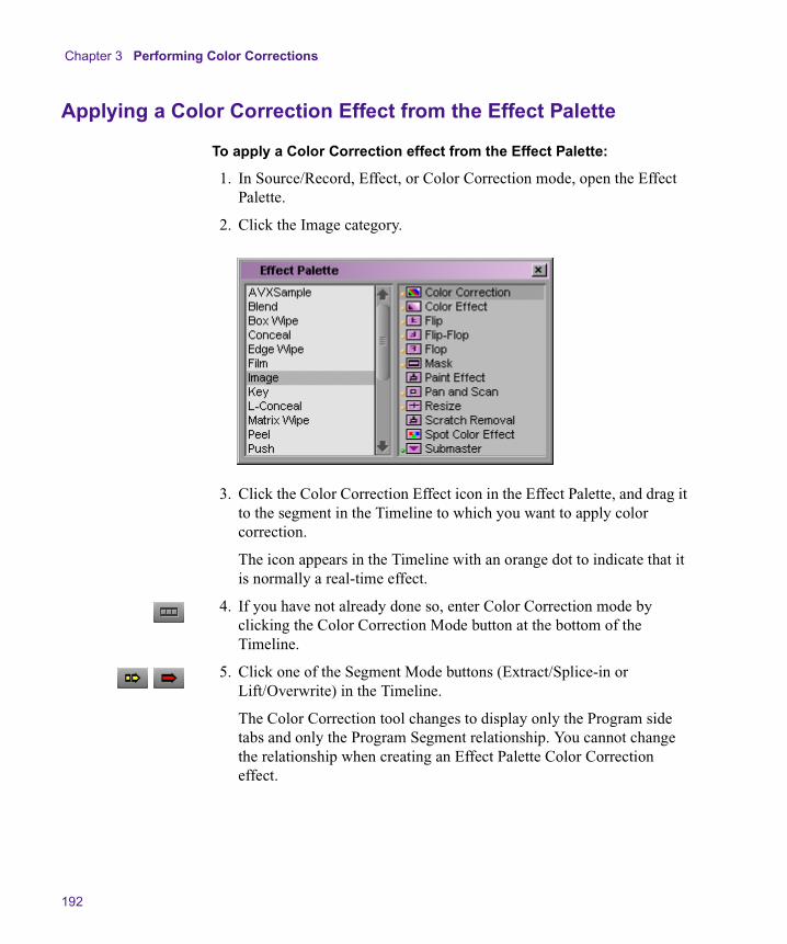
Chapter 3 Performing Color Corrections
192
Applying a Color Correction Effect from the Effect Palette
To apply a Color Correction effect from the Effect Palette:
1. In Source/Record, Effect, or Color Correction mode, open the Effect Palette.
2. Click the Image category.
3. Click the Color Correction Effect icon in the Effect Palette, and drag it to the segment in the Timeline to which you want to apply color correction.
The icon appears in the Timeline with an orange dot to indicate that it is normally a real-time effect.
4. If you have not already done so, enter Color Correction mode by clicking the Color Correction Mode button at the bottom of the Timeline.
5. Click one of the Segment Mode buttons (Extract/Splice-in or Lift/Overwrite) in the Timeline.
The Color Correction tool changes to display only the Program side tabs and only the Program Segment relationship. You cannot change the relationship when creating an Effect Palette Color Correction effect.
Using the Color Correction Effect in the Effect Palette
193
n You must click one of the Segment Mode buttons to associate your color correction adjustments with the Color Correction effect you have applied from the Effect Palette. For more information on the Segment Mode buttons, see “Using Segment Mode” in the chapter “Using the Timeline” in the editing guide.
6. Make adjustments in the Color Correction tool until you are satisfied with the result.
7. Enter Source/Record mode, and render the Color Correction effect using one of the rendering procedures described in “Rendering Effects” in the chapter “Playing and Rendering Effects” in the effects guide.
When the render is finished, the Color Correction Effect icon appears in the Timeline without a dot. If you transfer the sequence to an Avid system without color correction capability, the rendered effect will play successfully.
n Since Effect Palette Color Correction effects are real-time effects on your system, the ExpertRender feature does not normally select them for rendering. If you want to render Effect Palette Color Correction effects as part of an ExpertRender process, you must click Modify Selection in the Render Effects dialog box and select the Effect Palette Color Correction effects manually. For more information on using ExpertRender, see “ExpertRender” in the chapter “Playing and Rendering Effects” in the effects guide.

Chapter 3 Performing Color Corrections
194
Working with an Effect Palette Color Correction Effect
Once you have created a Color Correction effect from the Effect Palette and have made color correction adjustments to it, you can work with that effect in the same way that you work with any other effect that is applied from the Effect Palette and that appears in the Timeline with an effect icon.
You can save the effect as a template by entering Effect mode, clicking the effect icon in the Effect Editor, and dragging it to a bin in the standard way described in “Saving an Effect Template” in the chapter “Customizing Effects in Effect Mode” in the effects guide. You can then apply the template to other segments in the sequence or to other sequences. This is useful for applying an Effect Palette Color Correction effect quickly to multiple segments.
You can also delete the effect in the standard way by selecting it in Effect mode and pressing the Delete key. For more information, see “Deleting Effects in a Sequence” in the chapter “Basics of Effects Editing” in the effects guide. If color corrections that were not applied from the Effect Palette are in the same segment — indicated by colored lines if Color Correction is selected in the Timeline Fast menu — those corrections cannot be deleted in Effect mode. To remove those color corrections, you must enter Color Correction mode and use the Remove Effect button or the Remove Correction command in the Color Correction tool shortcut menu.
Chapter 4
Managing Color-Corrected Sequences
The Color Correction tool includes menu commands that allow you to manage sequences once they have color correction applied to them. You can update a sequence to apply existing color corrections to newly added segments, merge different versions of a color-corrected sequence, convert color corrections in a sequence to segment-only relationships, and remove groups of corrections from a sequence.
You can control the extent of the changes for all these operations. You can also choose to make the changes on a new copy of the sequence so that the unchanged sequence is still available to you.
• Updating Color-Corrected Sequences
• Merging Color-Corrected Sequences
• Flattening Color-Corrected Sequences
• Removing Color Corrections
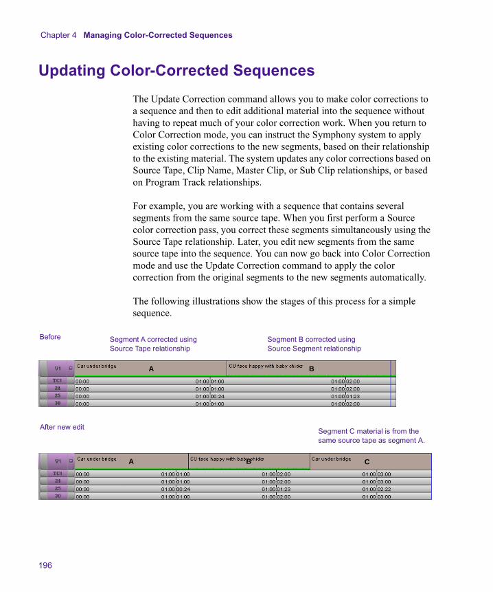
Chapter 4 Managing Color-Corrected Sequences
196
Updating Color-Corrected Sequences
The Update Correction command allows you to make color corrections to a sequence and then to edit additional material into the sequence without having to repeat much of your color correction work. When you return to Color Correction mode, you can instruct the Symphony system to apply existing color corrections to the new segments, based on their relationship to the existing material. The system updates any color corrections based on Source Tape, Clip Name, Master Clip, or Sub Clip relationships, or based on Program Track relationships.
For example, you are working with a sequence that contains several segments from the same source tape. When you first perform a Source color correction pass, you correct these segments simultaneously using the Source Tape relationship. Later, you edit new segments from the same source tape into the sequence. You can now go back into Color Correction mode and use the Update Correction command to apply the color correction from the original segments to the new segments automatically.
The following illustrations show the stages of this process for a simple sequence.
Before Segment A corrected using Source Tape relationship
Segment B corrected using Source Segment relationship
A B
After new edit Segment C material is from the same source tape as segment A.
A B C
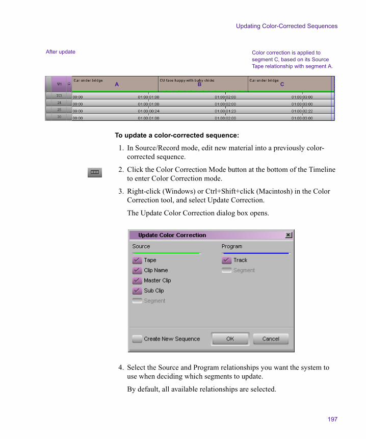
Updating Color-Corrected Sequences
197
To update a color-corrected sequence:
1. In Source/Record mode, edit new material into a previously color-corrected sequence.
2. Click the Color Correction Mode button at the bottom of the Timeline to enter Color Correction mode.
3. Right-click (Windows) or Ctrl+Shift+click (Macintosh) in the Color Correction tool, and select Update Correction.
The Update Color Correction dialog box opens.
4. Select the Source and Program relationships you want the system to use when deciding which segments to update.
By default, all available relationships are selected.
After update Color correction is applied to segment C, based on its Source Tape relationship with segment A.
A B C
Chapter 4 Managing Color-Corrected Sequences
198
5. Select Create New Sequence if you want the system to create a new copy of the sequence and update that copy.
n If you deselect Create New Sequence, the system will update the existing version of the sequence. Avid recommends that you create a new sequence when updating. You will then retain the previous version as a backup. If you update an existing version of a sequence and want to return to the previous version, select Edit > Undo.
6. Click OK.
The system updates the sequence and adds color correction to the appropriate new segments. If you have selected Create New Sequence, a new sequence appears in the bin with the title [OldTitle].Copy 1. You can rename the sequence to indicate more clearly that it is an updated version.
Merging Color-Corrected Sequences
Your workflow might make it useful to work with two versions of a sequence at the same time. For example, you might want an editor to work on one copy of a sequence while a colorist continues to make color adjustments on another copy. The Merge Correction command allows you to merge the two sequences to reflect the changes made on both copies.
Merge Correction merges any color corrections based on Source Tape, Clip Name, Master Clip, or Sub Clip relationships, or based on Program Track relationships, into the latest version of the edited sequence. For example, if the editor adds new segments from source tape 1, and a color correction exists for that source tape, the correction is applied to the new segments when the merge takes place. This is true whether the color correction was made before the editor began work or whether the color correction is made to the sequence while the editor is working with a copy of it.
You can also control which of the two copies the system prefers if there is a conflict between the two copies when merging.

Merging Color-Corrected Sequences
199
Using the Merge Correction Command
The Merge Correction process begins with the creation of a new sequence, which is then copied. The two copies are then worked on independently, before being merged using the Merge Correction command. You can separate the two copies before you make any color corrections, or you can make initial corrections and then separate the two copies.
To work with two copies of a sequence and then merge the corrections:
1. Create a first version of your sequence.
2. (Option) Click the Color Correction Mode button at the bottom of the Timeline to enter Color Correction mode, and make initial color adjustments to the sequence.
3. Save the sequence, and then create one or two copies of the sequence.
The way you handle copies of the sequence depends on the requirements of your workflow. You need only two versions of the sequence — the original and one copy. For example, the colorist might keep the original while the editor works on the copy. However, it might be safer to keep the original as a backup and to move forward in your workflow with two new copies.
n Take care to name your copies clearly. For example, if you are creating two copies as well as keeping the original, you might use the extensions .Editor, .Colorist, and .Original to distinguish the three versions.
n For more information on saving and copying a sequence, see “Basic Bin Procedures” in the chapter “Organizing with Bins” in the editing guide.
4. Continue to work on the two copies independently.
5. When you are ready to merge the two copies, enter Source/Record mode.
6. Load one copy of the sequence into the Source monitor and the other into the Record monitor.
You can load a copy into either monitor. The only difference is that the system will merge into the sequence in the Record monitor unless you instruct it to create a new sequence for the merge in step 11.
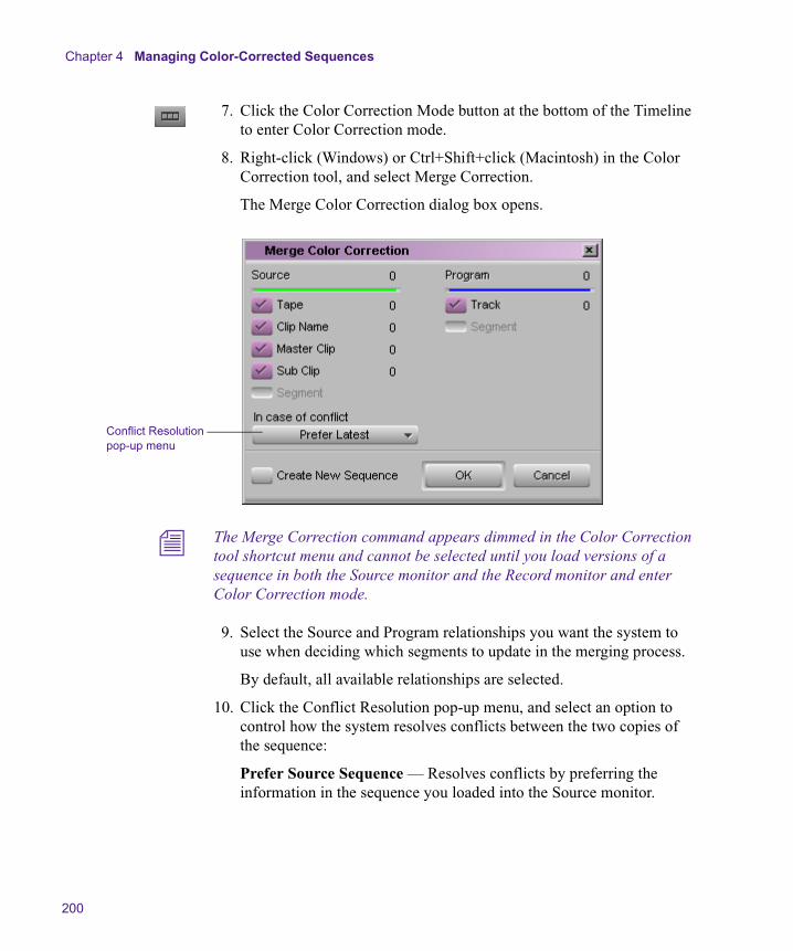
Chapter 4 Managing Color-Corrected Sequences
200
7. Click the Color Correction Mode button at the bottom of the Timeline to enter Color Correction mode.
8. Right-click (Windows) or Ctrl+Shift+click (Macintosh) in the Color Correction tool, and select Merge Correction.
The Merge Color Correction dialog box opens.
n The Merge Correction command appears dimmed in the Color Correction tool shortcut menu and cannot be selected until you load versions of a sequence in both the Source monitor and the Record monitor and enter Color Correction mode.
9. Select the Source and Program relationships you want the system to use when deciding which segments to update in the merging process.
By default, all available relationships are selected.
10. Click the Conflict Resolution pop-up menu, and select an option to control how the system resolves conflicts between the two copies of the sequence:
Prefer Source Sequence — Resolves conflicts by preferring the information in the sequence you loaded into the Source monitor.
Conflict Resolution pop-up menu

Merging Color-Corrected Sequences
201
Prefer Record Sequence — Resolves conflicts by preferring the information in the sequence you loaded into the Record monitor.
Prefer Latest — Resolves conflicts by preferring the most recent information. This is the default setting.
11. Select Create New Sequence if you want the system to create a new copy of the sequence and merge into that copy.
If you deselect this option, the system merges the two copies into the sequence that is currently in the Timeline. This is the sequence that you loaded into the Record monitor before entering Color Correction mode.
12. Click OK.
The system merges the two existing sequences, based on the options you have selected. The merged sequence appears in the Timeline.
Color Correction Merging Example
The following example illustrates the capabilities of the Merge Color Correction command.
The original sequence for this example consists of seven segments that are derived from four different source tapes. For simplicity, the segments are edited together in exactly equal one-second lengths. The following illustration shows the original sequence before any color correction is performed.
The numbers on the segments indicate the source tape from which each segment comes.
2 1 2 3 1 4 1
1. Original sequence

Chapter 4 Managing Color-Corrected Sequences
202
The sequence now receives some initial color correction. Source Tape correction is applied to the material from source tapes 2 and 4. The following illustration shows the sequence after this initial color correction work.
At this point in the workflow, a copy is made of the sequence and an editor continues to work on the copy. At the same time, further color corrections are made to the original version of the sequence.
The editor makes the following adjustments:
• The fifth segment is replaced by another clip from source tape 2.
• A new segment from source tape 4 is added near the end of the sequence.
• The second segment is trimmed to double its length.
Segments from source tapes 2 and 4 have Source Tape corrections.
2. Sequence after initial color correction
2 1 2 3 1 4 1
3. Editor’s copy of sequence after further editing
New segment from source tape 4
Replacement segment from source tape 2
Lengthened segment after trimming
2 1 2 3 4 4 12

Merging Color-Corrected Sequences
203
The colorist modifies his version of the sequence by adding Source Tape correction for source tape 1.
The editor’s copy of the sequence is now out-of-date with respect to the colorist’s corrections. It contains segments from source tapes 1, 2, and 4 that need to be updated to use the Source Tape corrections for those tapes. When the two sequences are merged, the editor’s sequence is correctly updated.
4. Colorist’s copy of sequence after further correctionSource Tape correction added for source tape 1
2 1 2 3 1 4 1
5. Merge process
Editor’s copy
Merged sequence
Source Tape correction is applied to new shots.
Editor’s trim appears in merged sequence.
Colorist’s new correction to source tape 1 is applied in the merged sequence.
2 1 2 3 4 4 12
2 1 2 3 4 4 12
Colorist’s copy
2 1 2 3 1 4 1
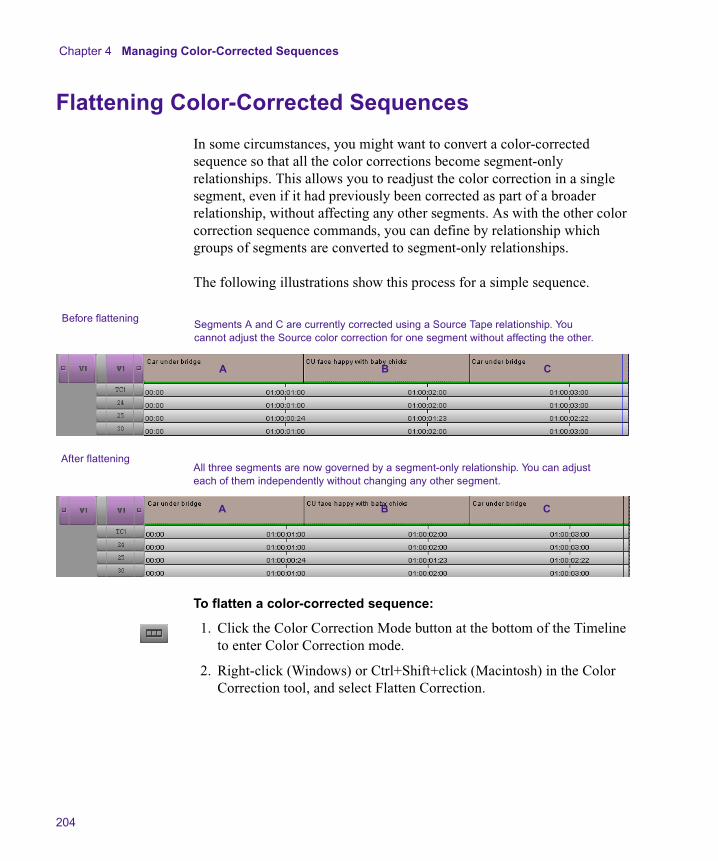
Chapter 4 Managing Color-Corrected Sequences
204
Flattening Color-Corrected Sequences
In some circumstances, you might want to convert a color-corrected sequence so that all the color corrections become segment-only relationships. This allows you to readjust the color correction in a single segment, even if it had previously been corrected as part of a broader relationship, without affecting any other segments. As with the other color correction sequence commands, you can define by relationship which groups of segments are converted to segment-only relationships.
The following illustrations show this process for a simple sequence.
To flatten a color-corrected sequence:
1. Click the Color Correction Mode button at the bottom of the Timeline to enter Color Correction mode.
2. Right-click (Windows) or Ctrl+Shift+click (Macintosh) in the Color Correction tool, and select Flatten Correction.
Before flatteningSegments A and C are currently corrected using a Source Tape relationship. You cannot adjust the Source color correction for one segment without affecting the other.
A B C
After flatteningAll three segments are now governed by a segment-only relationship. You can adjust each of them independently without changing any other segment.
A B C
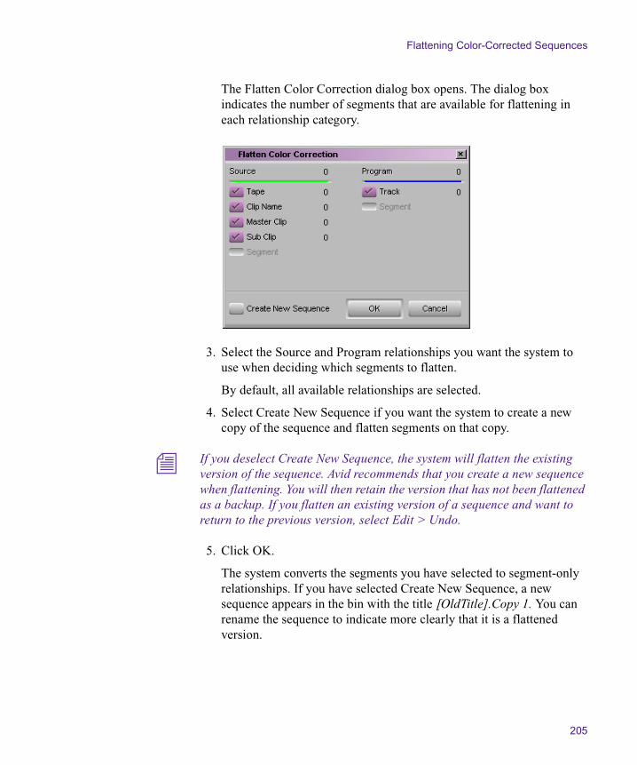
Flattening Color-Corrected Sequences
205
The Flatten Color Correction dialog box opens. The dialog box indicates the number of segments that are available for flattening in each relationship category.
3. Select the Source and Program relationships you want the system to use when deciding which segments to flatten.
By default, all available relationships are selected.
4. Select Create New Sequence if you want the system to create a new copy of the sequence and flatten segments on that copy.
n If you deselect Create New Sequence, the system will flatten the existing version of the sequence. Avid recommends that you create a new sequence when flattening. You will then retain the version that has not been flattened as a backup. If you flatten an existing version of a sequence and want to return to the previous version, select Edit > Undo.
5. Click OK.
The system converts the segments you have selected to segment-only relationships. If you have selected Create New Sequence, a new sequence appears in the bin with the title [OldTitle].Copy 1. You can rename the sequence to indicate more clearly that it is a flattened version.

Chapter 4 Managing Color-Corrected Sequences
206
Removing Color Corrections
You can remove the color correction on a specific segment at any time by clicking the Remove Effect button in the Composer window while in Color Correction mode. You can also remove groups of corrections with the same associated relationship using the Remove Correction command. This is useful for removing all corrections, or large numbers of corrections, at the same time.
To remove corrections using the Remove Correction command:
1. Click the Color Correction Mode button at the bottom of the Timeline to enter Color Correction mode.
2. Right-click (Windows) or Ctrl+Shift+click (Macintosh) in the Color Correction tool, and select Remove Correction.
The Remove Color Correction dialog box opens. The dialog box indicates the number of segments in the sequence for each relationship category.
Removing Color Corrections
207
3. Select the Source and Program relationships you want the system to use as the criteria for removing segments.
By default, all relationships are selected.
4. Select Create New Sequence if you want the system to create a new copy of the sequence and remove segments only from that copy.
n If you deselect Create New Sequence, the system will update the existing version of the sequence. Avid recommends that you create a new sequence when removing groups of corrections. You will then retain the previous version as a backup. If you remove corrections from the existing version of a sequence and want to return to the previous version, select Edit > Undo.
5. Click OK.
The system removes color correction for all segments governed by the relationships you have selected. If you have selected Create New Sequence, a new sequence appears in the bin with the title [OldTitle].Copy 1. You can rename the sequence to indicate more clearly that it is a version from which some corrections have been removed.

Chapter 4 Managing Color-Corrected Sequences
208
Chapter 5
Color Correction Techniques
This chapter provides a basic introduction to color correction techniques. It suggests some general principles to keep in mind when you are assessing footage and making color corrections. The chapter then presents several examples of shots with typical color problems and detailed explanations of adjustments that improve those shots.
This information is intended primarily for users who are unfamiliar with the methods of color correction and who want some initial guidance on how to handle material that needs correction. However, since the chapter is built around specific examples of color corrections made with the Color Correction tool, it might also be useful for anyone learning to work with the tool and its controls, even an experienced colorist.
• Guiding Principles for Color Correction
• Examples of Color Correction Problems
Chapter 5 Color Correction Techniques
210
Guiding Principles for Color Correction
One useful high-level way to think about the color correction process is to define what the overall goals of the process are. Another, slightly more practical and detailed, is to break down the typical color correction workflow into clearly defined stages of adjustment. This section uses these two approaches to provide you with a set of guiding principles for color correction.
Goals of Color Correction: Restoration and Adaptation
Color correction can be thought of as having two main goals. The first is restoring the original look of the scene. The second is adapting the look of the scene to meet the demands of the project.
In some cases, the task of color correction is complete when the first goal has been met. Often, however, there will be at least some departure from the restored look to achieve shot-to-shot consistency or to convey creative concepts. The color corrections applied to any particular shot must therefore respect (to varying degrees) two different contexts: the original scene at the time the camera captured it and the final situation of the shot within a program that has particular creative or communicative aims.
Restoring the Original Look
The first task in color correction is to restore the original look of the scene that has been filmed — in other words, to make the image match as closely as possible what an observer standing beside the camera would have perceived when the scene was shot.
This is important primarily because viewers have little tolerance for images that look unrealistic when they are supposed to represent reality. Viewers make some allowances for the fact that they are watching film or television rather than viewing the world directly, but they do not make many. For example, when a skin tone departs from our normal expectations of what skin should look like, we notice. Even when the final image is intentionally a distortion of reality, it is useful to restore the original look as a well-balanced foundation for subsequent alterations.

Guiding Principles for Color Correction
211
The color characteristics of a given shot can depart from the look of the original scene for a variety of reasons. At the time of shooting, the camera might not be correctly balanced or the scene might be imperfectly lit. During transfers (from film to tape, from one tape to another, or from tape to digitized media), inconsistencies in materials, processing methods, or calibration might alter the colors.
When you are working on an uncorrected shot, you should make intelligent decisions about what the scene originally looked like and then bring the shot into line with those decisions as much as possible. Since it is unlikely that you were present when the scene was shot, this might seem to require a great deal of guesswork, but, in fact, it can be accomplished with sufficient accuracy using the following two basic guidelines.
• The human visual system generally maximizes the tonal range available in a scene. For example, in low light we adjust to perceive a greater range of dark tones.
• The human visual system generally perceives color accurately and compensates for color casts. For example, we perceive a white shirt as white even if it is being illuminated by slightly pink light.
Generally, you can restore the original look of a shot (or at least create a believable approximation of the original look) by opening up the tonal range as much as reasonably possible and by ensuring that colors look accurate. For more detailed information on how to achieve this with adjustments, see “Correcting Tonal Range” on page 213 and “Neutralizing Color” on page 214, and the examples later in this chapter.
Adapting the Original Look
An adaptive adjustment deliberately departs from the original look of the scene in some way. Such an adjustment might be relatively subtle, for example, lightening one shot to make it match another. In this case, you are departing from your commitment to the original look in order to achieve shot-to-shot consistency in your sequence. Other kinds of adaptive adjustment might be much more dramatic, for example, applying a gold tint to an entire sequence for an advertising spot or applying extreme adjustments such as posterization or chroma inversion for a music video.

Chapter 5 Color Correction Techniques
212
Before you begin adaptive adjustments, you should try to achieve an effective restorative adjustment. You will then be building on an image that has good color characteristics. Most viewers can probably perceive the difference between a restored, well-balanced image with a strong blue tint applied and an unrestored, poorly lit image with a strong blue tint applied (and prefer the former).
Remember that your Symphony system is capable of two levels of color correction and that some kinds of adaptive adjustments, especially if they are to apply equally to every shot in a sequence, are best applied on the Program side. However, if your correcting work involves only restoration and simple matching for consistency from shot to shot, it is probably better to do all your work on the Source side. This keeps your color corrections as a whole simpler and preserves the Program side for any final adjustments that you might want to make.
Stages of Color Correction
A typical color correction for a shot will probably include the following main stages of adjustment:
• Correcting the tonal range (or contrast ratio)
• Neutralizing color casts
• Achieving consistency between the shots in a sequence
• Achieving a final look
Different kinds of projects will lead to different emphases among these stages and might even make some unnecessary. Different working habits will also affect how these stages are handled. A more experienced colorist might work in a manner that blurs the distinctions between them. For a beginner, it might be better to keep them distinct and achieve an acceptable result for each one before moving on to the next.
The following sections provide some guidelines for each main stage.
Guiding Principles for Color Correction
213
Correcting Tonal Range
Correcting the tonal range usually requires two steps. In the first step, you reset the white and black points to make the range of values between the lightest part of the image and the darkest part of the image as large as possible. In the second step, you adjust the gray point to control how much of the total tonal range falls above and how much below the middle value.
Setting White and Black Points
Setting the white point and the black point is often relatively straightforward, since the shot will include an area that should obviously be very light and another area that should be very dark. You simply look for what should be the lightest area of the image and adjust controls until it becomes as light as possible, and then do the same for the area that needs to be black. You can dramatically improve the quality of shots taken using insufficient or excessive light just by making white and black point adjustments.
In some cases, however, the shot should have less range of brightness (for example, when the whole scene was originally in shadow or was shot at sunset). In such cases, you need to be careful to expand the range as much as possible without making parts of the image unrealistically light or dark.
Avoid clipping any significant part of the image. You want the range between your lightest value and your darkest value to be as large as possible, but in most circumstances you don’t want to lose detail by reducing all your very light values to white or all your very dark values to black.
Do not use intense reflected spots of light (known as speculars) to judge where your white point should be. If you do so, you define white by an artificial standard that probably occurs in only a tiny fraction of the image. A true white object such as an item of clothing might appear dull and gray by this standard.
You have a number of choices for controls to use to make white point and black point adjustments, including the Gain and Setup sliders in the HSL tab and the various controls in the Levels tab.

Chapter 5 Color Correction Techniques
214
Adjusting the Gray Point
Once you have established the range from the brightest part of the image to the darkest part, you can adjust the gray point if necessary. When you make a gray point adjustment, you define how much of the overall tonal range is between black and mid-gray, and how much is between mid-gray and white.
The most obvious effect of a gray point adjustment is that it either lightens or darkens the overall look of the image. Large adjustments of the gray point toward either the black point or the white point are almost always undesirable because they leave the whole image much too dark or too light.
Smaller, well-chosen gray point adjustments, however, can be useful for fine-tuning the overall brightness of the image. Also, since a gray point adjustment expands the tonal range on one side of the midpoint and contracts it on the other, it can be useful for improving contrast and detail overall. For example, some images look better if more contrast is available in the range between gray and white, even though the price paid for that extra contrast is a reduction in contrast between gray and black.
The main controls for making gray point adjustments are the Gamma slider in the HSL group and the gray point controls in the Levels group.
Neutralizing Color
Neutralizing color involves returning the colors in an image to the colors that a viewer would have perceived when standing beside the camera. Most film or video images depart from that ideal to some degree, and some depart from it dramatically.
One way to think about neutralizing color is to imagine working on a project where every shot includes a large card that we know is, when viewed in ideal lighting conditions, a perfectly neutral mid-gray color. If you can correct each image so that the card appears mid-gray when your audience views the final program, all other colors in the images should be correct also.

Guiding Principles for Color Correction
215
Though you cannot normally have such a perfect measuring device in your images, it is useful to select an area of each image as a target for your color neutralizing adjustments. If you focus on getting the color in that area right, color in the rest of the image should fall into place. In some images, there might be an object or area that should be neutral gray, or nearly so, and you can use that area as your principal target as you make adjustments. In other images, you might not have any gray color at all, but you will almost certainly have some other area where even a small departure from neutral color is noticeable. Human skin is probably the most common example. Or you might choose to focus on an area where you know the true color, such as a person’s hair.
In addition to identifying parts of your image on which to concentrate your attention, it is useful to establish how the uncorrected image departs from neutral color before you attempt to correct it.
Sometimes this is obvious. You cannot mistake an image with an extreme pink or yellow cast. When the problem is more subtle, you can sample a few areas with the Color Match eyedropper to get information about the color characteristics of the image. Areas that should be white or black are particularly helpful, since these are easily identifiable colors that should have nearly identical values for red, green, and blue. If the red value is higher than the other two, the image has a red cast. If red and green are higher than blue, the image has a yellow cast.
You can neutralize color using many different controls in the Color Correction tool. For example, you can use the Curves tab to adjust the proportions of each color. You can use the Hue and Saturation sliders in the Highlights, Midtones, and Shadows tabs of the HSL group. Or you can use the Hue Offsets color wheels, which allow you to quickly locate the sector of the wheel that represents the color cast in the image, and then adjust in the opposite direction to that color. Except when a color problem is extreme, you will usually be more successful when neutralizing color if you make adjustments in individual colors or in specific brightness ranges rather than in the Master controls.
The more experienced you become as a colorist, the better you will get at judging even subtle color problems by eye and knowing intuitively what kinds of adjustments to make.

Chapter 5 Color Correction Techniques
216
Achieving Shot-to-Shot Consistency
The most common reason for departing from the look of the original shot is to achieve simple shot-to-shot consistency in the finished program. If a scene in a drama that is supposed to take place at one time is shot over two days, and lighting conditions have changed from one day to the next, you clearly want to adjust all the shots so that they appear to be taking place at the same time.
Adjustments for shot-to-shot consistency are relatively straightforward in most cases. You simply need to compare shots in the Composer window and then adjust them to match. If you have already adjusted tonal range and neutralized color well, a small change to relative brightness might be all that is needed.
The Dual Split with Reference option provides a particularly good way of comparing a reference shot with your correction to another shot to confirm that the two match. Small adjustments in relative brightness from one shot to another are also easily made with the Color Match control.
Depending on the requirements of your project, you might choose to make adjustments for shot-to-shot consistency on the Source side or on the Program side. If you have made a lot of earlier adjustments on the Source side and you know you do not need to make overall adjustments for a finished look, you might choose to move to the Program side to make shot-to-shot corrections. If you expect to need the Program side for significant finishing adjustments that apply across all the segments in your sequence, you will want to stay on the Source side when making shot-to-shot adjustments.
Achieving a Final Look
Some projects might require final adjustments to create a finished look. For example, you might slightly increase saturation across the whole sequence to create richer-looking colors or slightly darken all the shots to enhance a mood of tension or suspense. In certain circumstances, you might make substantial changes to the color values of the whole sequence or remove color entirely from some parts of it.
Examples of Color Correction Problems
217
You will usually make final corrections of this kind on the Program side by correcting entire program tracks or extended parts of sequences defined by IN and OUT points. It is not possible to generalize about which controls to use to make such adjustments. You might be called upon to use any combination of color correction controls. The only effective preparation for such work is practice using Color Correction mode and a good understanding of the more specific corrections discussed in the previous sections.
Examples of Color Correction Problems
The remainder of this chapter presents three typical color correction problems. The original images are chosen as good illustrations of the kind of color correction work that needs to be done to restore a good approximation of what an observer at the scene would have perceived when the camera was shooting. They require corrections to improve tonal range and to neutralize color casts.
Each example provides the following information:
• An analysis of the original image
• Step-by-step descriptions of the corrections with illustrations (including split-screen displays in some instances)
• Sample RGB values that illustrate the results of the corrections
• Suggestions for alternative ways to achieve similar results with the Color Correction tool
Remember that these examples are presented as aids to learning, not as inflexible instructions for making corrections or models of what a perfect corrected image looks like. Each example shows only one possible way of making a correction and one possibility for a final corrected image. As you develop your own color correcting skill and judgment, you might prefer to use different combinations of controls and to aim for a slightly different final look.
n If you are reading a hardcopy version of this document, you will find it useful to view the color images in the Help or in the online version of this document on the online publications CD-ROM.

Chapter 5 Color Correction Techniques
218
Example 1
Analysis of original image: This image has two obvious problems. First, it lacks contrast and detail because it does not have a full tonal range. A correction is required to improve sharpness and detail in areas such as the shirt and the man’s hair. Second, the image has a strong yellow-green cast. This leads in particular to a very unnatural skin tone.
Uncorrected Image

Examples of Color Correction Problems
219
Step 1 of this correction is an adjustment to the Contrast slider in the Master Controls tab of the HSL group. This adjustment (which sets the Contrast slider value to 11) illustrates one of the simplest ways to affect the tonal range of an image. Despite its simplicity, the correction improves the image noticeably. Compare the look of the man’s hair on either side of the split-screen dividing line.
Step 1: Contrast Correction
Split Screen: Uncorrected Image and Step 1 Correction

Chapter 5 Color Correction Techniques
220
Step 2 of this correction eliminates the color cast by making a single adjustment on the Master Hue Offsets color wheel in the HSL group. Since the image is obviously too green, the correction is made by moving the crosshair pointer away from green. The adjustment shown is Hue:–94, Amount:11. (This places the crosshair between the magenta and blue parts of the wheel, opposite a point between green and yellow. The sample RGB values below confirm that we are reducing both yellow and green in the image.) This successfully restores a good skin tone and reveals the man’s shirt to be blue.
Step 2: Correction to Neutralize Color
Split Screen: Uncorrected Image and Image After All Corrections
Examples of Color Correction Problems
221
Sample RGB values: A sampling of an area of the man’s shirt before and after the corrections shows the following values:
Before: R:37, G:56, B:61
After: R:14, G:26, B:55
These numbers reinforce the nature of the corrections that have been made. The hue offset adjustment has reduced the red and green levels significantly while preserving the amount of blue in the image.
Alternative techniques: This example uses simple corrections that apply across the full luminance range. Another method for correcting this image would involve making individual adjustments in different ranges such as highlights and shadows. For an illustration of this approach, see “Example 2” on page 222. The contrast adjustments could be made using the Gain, Gamma, and Setup sliders as an alternative to the one adjustment on the Contrast slider. Another alternative for making the contrast adjustment would be to use the controls in the Levels tab.
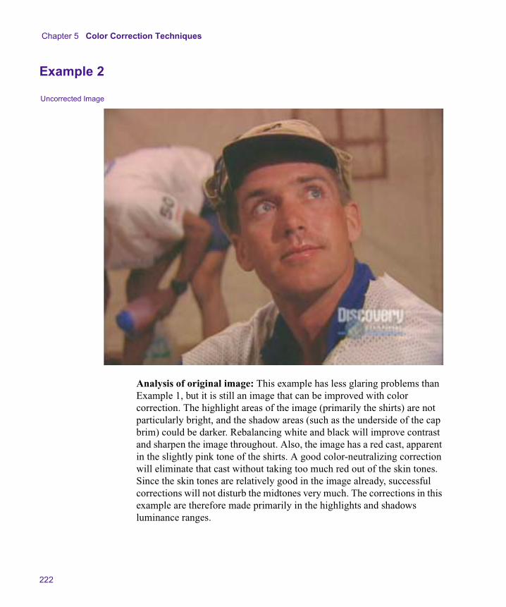
Chapter 5 Color Correction Techniques
222
Example 2
Analysis of original image: This example has less glaring problems than Example 1, but it is still an image that can be improved with color correction. The highlight areas of the image (primarily the shirts) are not particularly bright, and the shadow areas (such as the underside of the cap brim) could be darker. Rebalancing white and black will improve contrast and sharpen the image throughout. Also, the image has a red cast, apparent in the slightly pink tone of the shirts. A good color-neutralizing correction will eliminate that cast without taking too much red out of the skin tones. Since the skin tones are relatively good in the image already, successful corrections will not disturb the midtones very much. The corrections in this example are therefore made primarily in the highlights and shadows luminance ranges.
Uncorrected Image
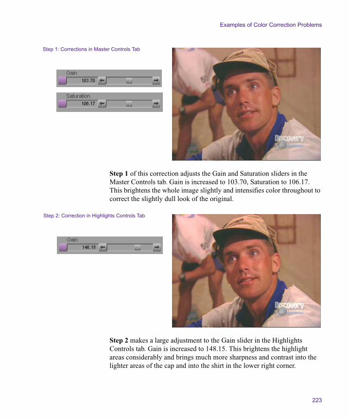
Examples of Color Correction Problems
223
Step 1 of this correction adjusts the Gain and Saturation sliders in the Master Controls tab. Gain is increased to 103.70, Saturation to 106.17. This brightens the whole image slightly and intensifies color throughout to correct the slightly dull look of the original.
Step 2 makes a large adjustment to the Gain slider in the Highlights Controls tab. Gain is increased to 148.15. This brightens the highlight areas considerably and brings much more sharpness and contrast into the lighter areas of the cap and into the shirt in the lower right corner.
Step 1: Corrections in Master Controls Tab
Step 2: Correction in Highlights Controls Tab
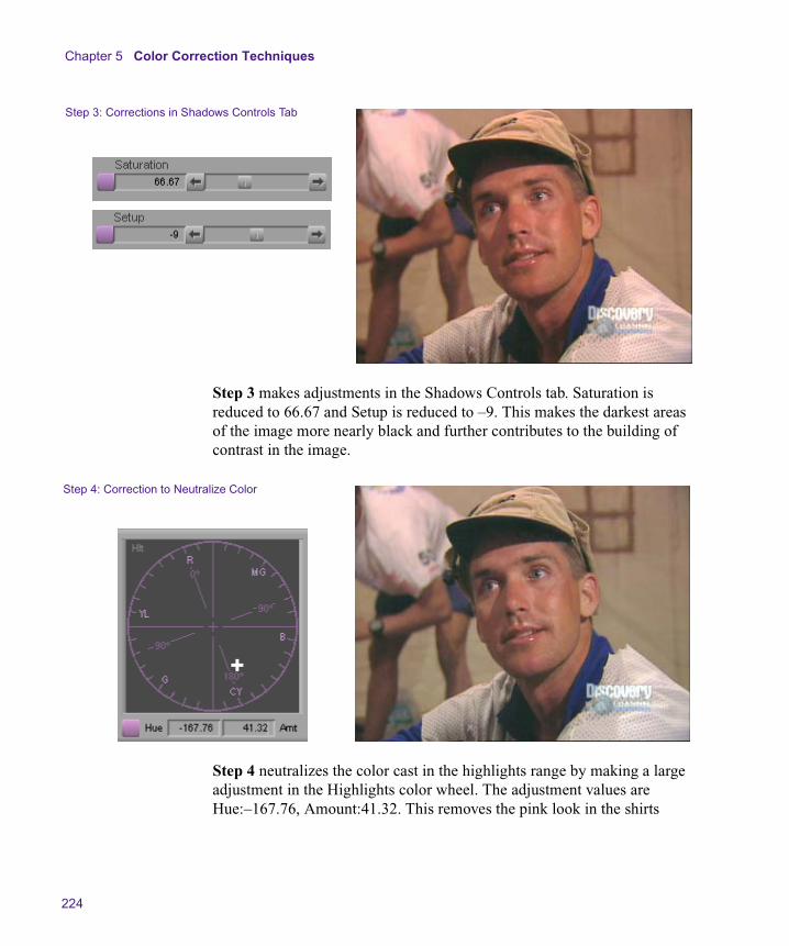
Chapter 5 Color Correction Techniques
224
Step 3 makes adjustments in the Shadows Controls tab. Saturation is reduced to 66.67 and Setup is reduced to –9. This makes the darkest areas of the image more nearly black and further contributes to the building of contrast in the image.
Step 4 neutralizes the color cast in the highlights range by making a large adjustment in the Highlights color wheel. The adjustment values are Hue:–167.76, Amount:41.32. This removes the pink look in the shirts
Step 3: Corrections in Shadows Controls Tab
Step 4: Correction to Neutralize Color

Examples of Color Correction Problems
225
(most apparent by comparing the shirt in the background between Step 3 and Step 4). Since the adjustment is made in the highlights range only, it doesn’t result in an extreme loss of the red component of the skin tones.
Sample RGB values: A sampling of the darkest shadow area of the cap before and after the corrections shows the following values:
Before: R:24, G:24, B:22
After: R:14, G:15, B:17
These values confirm that corrections in the shadows area have resulted in shadows that are a more intense black.
Alternative techniques: The Curves tab is the only other part of the Color Correction tool that allows adjustments that affect luminance ranges differently in the manner of this example. A similar final result could probably be achieved in the Levels tab, but the adjustments there are made on individual color channels rather than on different overall luminance ranges.
Split Screen: Uncorrected Image and Image After All Corrections

Chapter 5 Color Correction Techniques
226
Example 3
Uncorrected Image
Reference Image

Examples of Color Correction Problems
227
Analysis of original image: In this example, two different cameras have been used to shoot the rock climbers. The second camera is correctly balanced and shows good color characteristics. In comparison, the images from the first camera show a pronounced blue cast. Also, the image from the first camera is too dark. Because the images from the two cameras look so different from one another, and because the first image is intrinsically weak, corrections are needed to neutralize color and raise the brightness level in the first image. The image from the good camera can be used as a reference as these corrections are made. In this example, the corrections are made in the Curves tab. One advantage of Curves tab adjustments, if you are practiced and comfortable with them, is that you can make quite complex changes without having to alter many controls. The corrections in this example are made by adding and moving a single control point in each of two Curves tab graphs.

Chapter 5 Color Correction Techniques
228
Step 1 of this correction removes the excess blue in the image by adjusting the Blue curve in the Curves tab. A control point is placed near the center of the curve since the adjustment needs to apply relatively evenly across the whole luminance range. The control point is then dragged down to reduce blue. The input and output values for this adjustment are 142 and 104 respectively.
Step 1: Correction to Neutralize Color
Split Screen: Uncorrected Image and Step 1 Correction
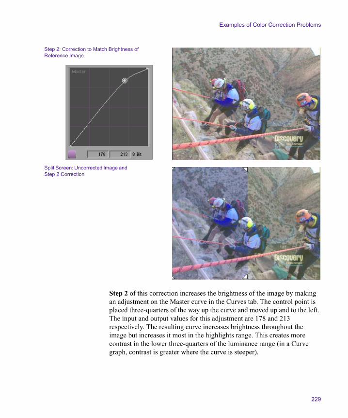
Examples of Color Correction Problems
229
Step 2 of this correction increases the brightness of the image by making an adjustment on the Master curve in the Curves tab. The control point is placed three-quarters of the way up the curve and moved up and to the left. The input and output values for this adjustment are 178 and 213 respectively. The resulting curve increases brightness throughout the image but increases it most in the highlights range. This creates more contrast in the lower three-quarters of the luminance range (in a Curve graph, contrast is greater where the curve is steeper).
Step 2: Correction to Match Brightness of Reference Image
Split Screen: Uncorrected Image and Step 2 Correction
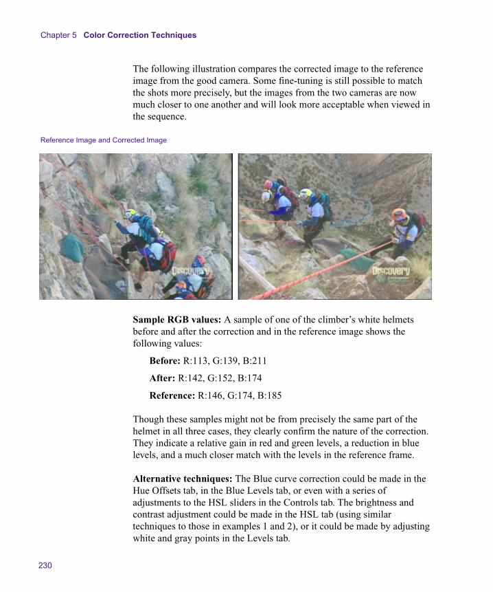
Chapter 5 Color Correction Techniques
230
The following illustration compares the corrected image to the reference image from the good camera. Some fine-tuning is still possible to match the shots more precisely, but the images from the two cameras are now much closer to one another and will look more acceptable when viewed in the sequence.
Sample RGB values: A sample of one of the climber’s white helmets before and after the correction and in the reference image shows the following values:
Before: R:113, G:139, B:211
After: R:142, G:152, B:174
Reference: R:146, G:174, B:185
Though these samples might not be from precisely the same part of the helmet in all three cases, they clearly confirm the nature of the correction. They indicate a relative gain in red and green levels, a reduction in blue levels, and a much closer match with the levels in the reference frame.
Alternative techniques: The Blue curve correction could be made in the Hue Offsets tab, in the Blue Levels tab, or even with a series of adjustments to the HSL sliders in the Controls tab. The brightness and contrast adjustment could be made in the HSL tab (using similar techniques to those in examples 1 and 2), or it could be made by adjusting white and gray points in the Levels tab.
Reference Image and Corrected Image
Chapter 6
Spot Color Correction
Your Symphony system allows you to apply color adjustments to parts of images that you define by drawing. You can make these adjustments using the Spot Color Correction effect or using color adjustment modes in the Paint Effect. Both effects include the Color Match control for making automatic adjustments based on selected input and output colors.
• Using the Spot Color Correction Effect
• Using Paint Effect Modes for Color Adjustment

Chapter 6 Spot Color Correction
232
Using the Spot Color Correction Effect
The Spot Color Correction effect allows you to make precise color adjustments to a part of an image that you define using the Intraframe™ drawing tools. For example, you can outline a figure in a shot or isolate a single object and then adjust the color of that figure or object without affecting the color of the rest of the image. As with other Intraframe effects, you can use keyframes to adjust the effect over time.
Spot color correction is commonly used as a storytelling device that emphasizes part of an image by giving it distinct color characteristics. You can also make color corrections using spot color correction whenever you want a color adjustment to be restricted to part of the image only.
In many circumstances, you can correct the color in selected areas of an image more quickly and easily using the secondary color correction capabilities of the Color Correction tool. However, color corrections that define part of an image using drawing tools are sometimes the only way to isolate the exact area of an image that you need to correct. For more information on secondary color correction, see “The Secondary Group” on page 149.
The following illustrations show two basic examples of spot color correction. In the first example, the background of the shot is outlined with a drawing tool and then desaturated and lightened, leaving the car as the only part of the image in color. Additional shapes within the main outline of the car have been used to remove any color visible through the car’s windows. In the second example, the straw bale on the left is outlined with a drawing tool and then enhanced with color adjustments to give it a stronger golden-yellow appearance.
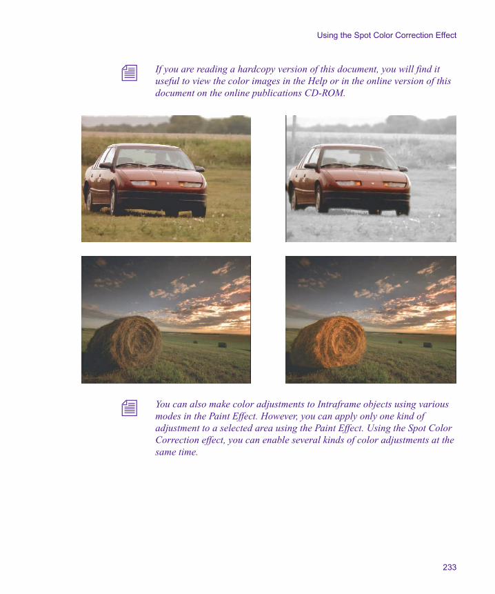
Using the Spot Color Correction Effect
233
n If you are reading a hardcopy version of this document, you will find it useful to view the color images in the Help or in the online version of this document on the online publications CD-ROM.
n You can also make color adjustments to Intraframe objects using various modes in the Paint Effect. However, you can apply only one kind of adjustment to a selected area using the Paint Effect. Using the Spot Color Correction effect, you can enable several kinds of color adjustments at the same time.

Chapter 6 Spot Color Correction
234
Making Corrections Using the Spot Color Correction Effect
To make corrections using the Spot Color Correction effect:
1. Select Tools > Effect Palette.
The Effect Palette opens.
2. Click the Image category.
3. Click the Spot Color Correction Effect icon in the Effect Palette, and drag it to the segment you want to correct in the Timeline.
4. Click the Effect Mode button to enter Effect mode.
5. From the Effect Editor, select a drawing tool, such as the Polygon tool.
6. Use the drawing tool to define the area on the image that you want to correct.
For more information on working with the Intraframe drawing tools, see the chapter “Intraframe Editing” in the effects guide.
7. Adjust parameters in the Effect Editor until you are satisfied with the look of your correction.
For information on the parameters available, see Table 18 on page 235.
8. (Option) If necessary, repeat steps 3 through 6 to define and adjust additional areas for correction.
9. (Option) If necessary, use keyframes to adjust the corrected areas over time so that they follow movements in the footage.
For more information on keyframing Intraframe objects, see “Animating the AniMatte™ Effect” in the chapter “Intraframe Editing” in the effects guide.
10. Render the effect to play it back in real time.

Using the Spot Color Correction Effect
235
Spot Color Correction Parameters
Table 18 lists the parameter categories available in the Spot Color Correction effect.
Table 18 Spot Color Correction Parameters
Parameter Description
Acceleration Adjusts the effect’s speed over time by having the effect ease in and ease out of every keyframe. For more information, see “Acceleration” in the chapter “2D Reference” in the effects guide.
Tracking Allows you to use tracking data to control the movement of the effect. For more information, see the chapter “Motion Tracking and Stabilization” in the effects guide.
Luma Adjust Adjusts the brightness and contrast of the selected area. For more information, see “Color Effect Parameters” in the chapter “2D Reference” in the effects guide.
Luma Range Adjusts the range of brightness from black to white and the position of the midtone point with respect to the white and black points. For more information, see “Color Effect Parameters” in the chapter “2D Reference” in the effects guide.
Luma Clip Determines the levels at which the system limits the brightness or darkness in the selected area. For more information, see “Color Effect Parameters” in the chapter “2D Reference” in the effects guide.
Chroma Adjust Adjusts the hue and saturation of colors in the selected area. For more information, see “Color Effect Parameters” in the chapter “2D Reference” in the effects guide.
Color Style Adjusts the selected area to create posterization and solarization effects. For more information, see “Color Effect Parameters” in the chapter “2D Reference” in the effects guide.
Color Gain Provides individual adjustments of the three color channels (red, green, and blue). For more information, see “Color Effect Parameters” in the chapter “2D Reference” in the effects guide.

Chapter 6 Spot Color Correction
236
Color Match
This parameter category provides the same Color Match control that appears in the Color Correction tool. The Color Match control allows you to adjust the color automatically in the selected area, based on selected input and output color values.
Click the Use NaturalMatch button to enable the NaturalMatch feature.
For more information on the Color Match control and the NaturalMatch feature, see “Using the Color Match Control” on page 80 and “Color Match” in the chapter “2D Reference” in the effects guide.
Feathering Adds soft edges to the selected area. For more information, see “AniMatte and Paint Effects” in the chapter “2D Reference” in the effects guide.
Magic Mask Applies effects across a series of frames using the chroma and luma values as the criteria for edge detection. For more information, see “AniMatte and Paint Effects” in the chapter “2D Reference” in the effects guide.
Brush Defines the shape, size, and softness of the brush for creating brushstrokes on an image. For more information, see “AniMatte and Paint Effects” in the chapter “2D Reference” in the effects guide.
Grid Defines the type of grid associated with the effect. For more information, see “Grid” in the chapter “2D Reference” in the effects guide.
Table 18 Spot Color Correction Parameters (Continued)
Parameter Description
Using Paint Effect Modes for Color Adjustment
237
Using Paint Effect Modes for Color Adjustment
Using some of the modes in the Paint Effect, you can adjust the color of a selected area that you have defined.
The main difference between color correction using the Paint Effect and color correction using the Spot Color Correction effect is that the Paint Effect can be used to apply only one kind of color adjustment. For example, you can adjust the luma range of a selected area by selecting the Luma Range mode of the Paint Effect, but you cannot then make an adjustment to the red color channel using the Color Gain mode. The Paint Effect can apply only one mode to an object.
To make a correction to an area in an image using a Paint Effect mode:
1. Select Tools > Effect Palette.
The Effect Palette opens.
2. Click the Image category.
3. Click the Paint Effect icon in the Effect Palette, and drag it to the segment you want to correct in the Timeline.
4. Click the Effect Mode button to enter Effect mode.
5. From the Effect Editor, select a drawing tool, such as the Polygon tool.
6. Use the drawing tool to define the area on the image that you want to correct.
For more information on working with the Intraframe drawing tools, see the chapter “Intraframe Editing” in the effects guide.
7. In the Mode parameter category, click the Fast Menu button, and select a color adjustment mode.
For information on available modes, see Table 19.

Chapter 6 Spot Color Correction
238
8. Adjust the parameters in the Mode parameter category until you are satisfied with the look of your correction.
9. (Option) If necessary, repeat steps 3 through 6 to define and adjust additional areas for correction.
10. (Option) If necessary, use keyframes to adjust the corrected areas over time so that they follow movements in the footage.
For more information on keyframing Intraframe objects, see “Animating the AniMatte Effect” in the chapter “Intraframe Editing” in the effects guide.
11. Render the effect to play it back in real time.
Table 19 describes the Paint Effect modes that provide color adjustments and are available only with the Color Correction option. For information on other Paint Effect modes, see “AniMatte and Paint Effects” in the chapter “2D Reference” in the effects guide.
Table 19 Paint Effect Modes for Color Adjustment
Mode Description
Color Adjust Adjusts the brightness, contrast, hue, and saturation of the selected area. Inverts the chroma and luma values of the selected area. For more information, see “Luma Adjust” and “Chroma Adjust” in the chapter “2D Reference” in the effects guide.
Luma Range Adjusts the range of brightness from black to white and the position of the midtone point with respect to the white and black points. For more information, see “Color Effect Parameters” in the chapter “2D Reference” in the effects guide.
Luma Clip Determines the levels at which the system limits the brightness or darkness in the selected area. For more information, see “Color Effect Parameters” in the chapter “2D Reference” in the effects guide.

Using Paint Effect Modes for Color Adjustment
239
Color Style Adjusts the selected area to create posterization and solarization effects. For more information, see “Color Effect Parameters” in the chapter “2D Reference” in the effects guide.
Color Gain Provides individual adjustments of the three color channels (red, green, and blue). For more information, see “Color Effect Parameters” in the chapter “2D Reference” in the effects guide.
Color Match
This parameter category provides the same Color Match control that appears in the Color Correction tool. The Color Match control allows you to adjust the color automatically in the selected area, based on selected input and output color values.
Click the Enable Color Match button to activate the color match for the selected area.
Click the Use NaturalMatch button to enable the NaturalMatch feature.
For more information on the Color Match control and the NaturalMatch feature, see “Using the Color Match Control” on page 80.
Table 19 Paint Effect Modes for Color Adjustment (Continued)
Mode Description
Chapter 6 Spot Color Correction
240

Chapter 7
Safe Color Limiting and Warning
This chapter describes the Safe Colors feature of your Symphony system’s color correction tools. Safe Colors allows you to set safe limits for the colors that display in your images. The system either warns you when the limits are exceeded or automatically limits the colors in accordance with your settings.
• Overview of Safe Color Limits
• Setting Safe Color Limits
• Understanding the Graphical View of Safe Color Settings
• Understanding Safe Color Warnings
• Safe Color Behavior with Effect and DSK Colors
• Safe Color Limits with Waveform and Vectorscope Information
Chapter 7 Safe Color Limiting and Warning
242
Overview of Safe Color Limits
Your system allows you to set three different types of safe color limits. You can limit the composite signal range, the luminance range, and the RGB gamut.
Most broadcasting companies set specific limits for the composite signal and the luminance range. Programs that do not meet these limits are not normally accepted for broadcast. For example, a typical set of limits for broadcast in the United States might restrict the composite signal to a range from –20 IRE to 110 IRE and limit the maximum luminance to approximately 100 IRE. Some broadcast standards might be even stricter than these values, while others might be somewhat more permissive.
n The composite signal for a program intended for broadcast should never exceed 120 IRE, which is the highest level that can be broadcast.
If you are working on a program intended for broadcast, you should determine what the safe limits for composite and luminance are and type them in the appropriate areas of the Safe Color Settings dialog box. You can then instruct the system to warn you when those limits are exceeded or to automatically limit your colors to those limits. For more information, see “Setting Safe Color Limits” on page 243.
RGB gamut refers to the intensity of each individual color channel — red, green, and blue. This measure of a safe color is less likely to be subject to specific broadcast standards, but it is still an important limit type. Colors that have extremely low or high gamut values might not display well on television screens.
You can monitor several different kinds of material using the Safe Colors feature, including video, colors generated as part of effects, and colors in downstream key (DSK) titles and graphics. Because of the way the Safe Colors feature interacts with other features in your system and the order in which parts of the final image are processed, safe color monitoring behavior varies when handling effect and DSK colors. For more information, see “Safe Color Behavior with Effect and DSK Colors” on page 254.

Setting Safe Color Limits
243
Setting Safe Color Limits
You set safe color limits and control how those limits are applied by selecting options in the Safe Color Settings dialog box.
n If you are reading a hardcopy version of this document, you will find it useful to view the color images in the Help or in the online version of this document on the online publications CD-ROM.
To select safe color options:
1. Open the Safe Color Settings dialog box by doing one of the following:
t In the Project window, click the Settings tab, and then double-click Safe Colors in the Settings scroll list.
t In the Color Correction tool, click the Safe Color Settings button.
n The Safe Color Settings button in the Color Correction tool provides a visual indication of the status of the Safe Colors feature. If the Effect Colors or Video option is selected and either Limit or Warn is selected in one or more of the Actions pop-up menus, the icon on the Safe Color Settings button appears orange to indicate that at least some of the Safe Colors options are active. Otherwise, the icon on the Safe Color Settings button appears black.
The Safe Color Settings dialog box opens.
Actions pop-up menus
Units pop-up menus
Chapter 7 Safe Color Limiting and Warning
244
2. For each limit type, set the limits that you want by doing the following:
a. Select the unit of measurement you want to use from the Units pop-up menu.
b. Type the low and high limit values that you want in the Low and High text boxes.
c. Select the action that you want the system to take from the Actions pop-up menu.
Table 20 provides more information on the options available in the Safe Color Settings dialog box. The graphical view at the bottom of the Safe Color Settings dialog box shows the current limits in relation to the default limits in an easy-to-read format. For more information, see “Understanding the Graphical View of Safe Color Settings” on page 247.
3. Select the type of material to which you want your limits to apply by clicking the appropriate check boxes.
Table 20 describes the options available.
4. Click OK.
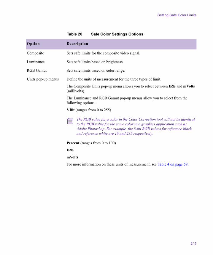
Setting Safe Color Limits
245
Table 20 Safe Color Settings Options
Option Description
Composite Sets safe limits for the composite video signal.
Luminance Sets safe limits based on brightness.
RGB Gamut Sets safe limits based on color range.
Units pop-up menus Define the units of measurement for the three types of limit.
The Composite Units pop-up menu allows you to select between IRE and mVolts (millivolts).
The Luminance and RGB Gamut pop-up menus allow you to select from the following options:
8 Bit (ranges from 0 to 255)
n The RGB value for a color in the Color Correction tool will not be identical to the RGB value for the same color in a graphics application such as Adobe Photoshop. For example, the 8-bit RGB values for reference black and reference white are 16 and 235 respectively.
Percent (ranges from 0 to 100)
IRE
mVolts
For more information on these units of measurement, see Table 4 on page 59.
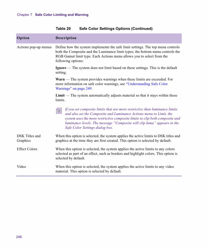
Chapter 7 Safe Color Limiting and Warning
246
Actions pop-up menus Define how the system implements the safe limit settings. The top menu controls both the Composite and the Luminance limit types; the bottom menu controls the RGB Gamut limit type. Each Actions menu allows you to select from the following options:
Ignore — The system does not limit based on these settings. This is the default setting.
Warn — The system provides warnings when these limits are exceeded. For more information on safe color warnings, see “Understanding Safe Color Warnings” on page 249.
Limit — The system automatically adjusts material so that it stays within these limits.
n If you set composite limits that are more restrictive than luminance limits and also set the Composite and Luminance Actions menu to Limit, the system uses the more restrictive composite limits to clip both composite and luminance levels. The message “Composite will clip luma” appears in the Safe Color Settings dialog box.
DSK Titles and Graphics
When this option is selected, the system applies the active limits to DSK titles and graphics at the time they are first created. This option is selected by default.
Effect Colors When this option is selected, the system applies the active limits to any colors selected as part of an effect, such as borders and highlight colors. This option is selected by default.
Video When this option is selected, the system applies the active limits to any video material. This option is selected by default.
Table 20 Safe Color Settings Options (Continued)
Option Description

Understanding the Graphical View of Safe Color Settings
247
Understanding the Graphical View of Safe Color Settings
The Safe Color Settings dialog box includes a graphical indication of the current limit values in relation to the default values. This allows you to quickly check that your limits are consistent with one another and within an acceptable range without having to read all the numerical limit values and remember the default values.
The following illustration shows the location of this graph within the Safe Color Settings dialog box. All settings in this illustration are at their default values.
n If you are reading a hardcopy version of this document, you will find it useful to view the color images in the Help or in the online version of this document on the online publications CD-ROM.
The graph shows colored bars that represent the current low and high levels for each limit type. The colors are the same as those used to display safe color warnings in the monitors. It also displays gray vertical lines that represent the default high and low levels for each limit type.
Safe Color Settings graph
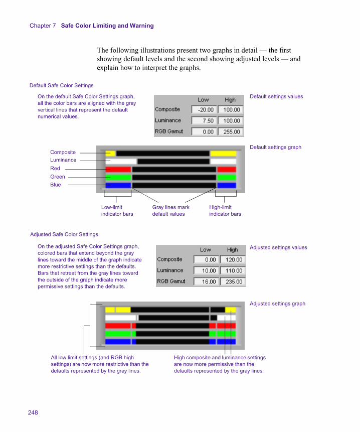
Chapter 7 Safe Color Limiting and Warning
248
The following illustrations present two graphs in detail — the first showing default levels and the second showing adjusted levels — and explain how to interpret the graphs.
Default Safe Color Settings
Default settings values
Default settings graph
On the default Safe Color Settings graph, all the color bars are aligned with the gray vertical lines that represent the default numerical values.
CompositeLuminance
Red
Green
Blue
Low-limit indicator bars
High-limit indicator bars
Gray lines mark default values
Adjusted settings values
Adjusted settings graph
Adjusted Safe Color Settings
On the adjusted Safe Color Settings graph, colored bars that extend beyond the gray lines toward the middle of the graph indicate more restrictive settings than the defaults. Bars that retreat from the gray lines toward the outside of the graph indicate more permissive settings than the defaults.
High composite and luminance settings are now more permissive than the defaults represented by the gray lines.
All low limit settings (and RGB high settings) are now more restrictive than the defaults represented by the gray lines.
Understanding Safe Color Warnings
249
Understanding Safe Color Warnings
If the Warn option is selected in the Actions pop-up menu for one or more of the types of safe limit, the system displays warnings in several areas of the Color Correction mode display when material exceeds the limits you have set. Warnings appear in the monitors and in the Levels tab histograms for all limit types. Warnings appear in the Color Match control for RGB Gamut limits only.
n Warning indicators do not appear unless color levels exceed at least one of the limits currently set to Warn.
When your system displays safe color warnings, you have the following options.
• Leave your color correction adjustments at the current settings. In this case, your program will continue to exceed some or all of the limits you have set.
• Instruct the system to limit the color levels automatically by selecting Limit from the appropriate Actions pop-up menus in the Safe Color Settings dialog box.
• Make manual color correction adjustments to bring levels within limits. The simplest way to do this is by making adjustments to the output histograms in the Levels tab. For more information, see “Adjusting Color Levels to Achieve Safe Limits” on page 253. When all levels are within limits, the warning indicators no longer appear.
Safe Color Warnings in the Monitors
In Color Correction mode, the Safe Color Warning icon (an orange triangle) appears in the top corner of a monitor in the Composer window if the frame currently displayed in that monitor exceeds the safe limits you have set.

Chapter 7 Safe Color Limiting and Warning
250
n Safe color warnings appear when you exceed limits in either field of the frame if you are working with two-field media. The histogram displays, however, normally reflect the distribution of colors in only the odd field of two-field media. If a warning appears in a monitor but you cannot see a warning area on the corresponding histogram, the pixels that are outside the limits you have set might be in the even field. To move through video material one field at a time and see histograms for every field, use the Step Forward One Field button or the Step Backward One Field button. In Color Correction mode, these buttons are available on the Move tab of the Command palette. You can also map these buttons to your keyboard to use them quickly when in Color Correction mode.
Alongside the Safe Color Warning icon, color-coded warning indicators provide a visual indication of the limits that are being exceeded. There are three rows for these indicators. An indicator appears in the top row if the limit is being exceeded at the high end and in the bottom row if the limit is being exceeded at the low end. If a limit type is within safe limits, an indicator appears in the center row. Table 21 lists the limit types and their associated colors as they appear left to right in each row.
The following illustrations show the layout of the Safe Color Warning display in the monitors, with examples of two typical presentations of Safe Color information.
Table 21 Safe Color Warning Indicators
Limit Type Color Code
Composite Yellow
Luminance White
RGB Gamut: Red Red
RGB Gamut: Green Green
RGB Gamut: Blue Blue
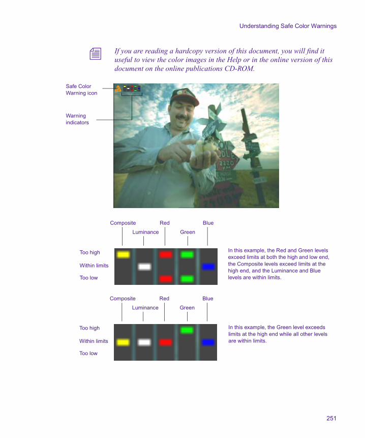
Understanding Safe Color Warnings
251
n If you are reading a hardcopy version of this document, you will find it useful to view the color images in the Help or in the online version of this document on the online publications CD-ROM.
Safe Color Warning icon
Warning indicators
Composite Red Blue
Luminance Green
Too high
Within limits
Too low
In this example, the Red and Green levels exceed limits at both the high and low end, the Composite levels exceed limits at the high end, and the Luminance and Blue levels are within limits.
Composite Red Blue
Luminance Green
Too high
Within limits
Too low
In this example, the Green level exceeds limits at the high end while all other levels are within limits.
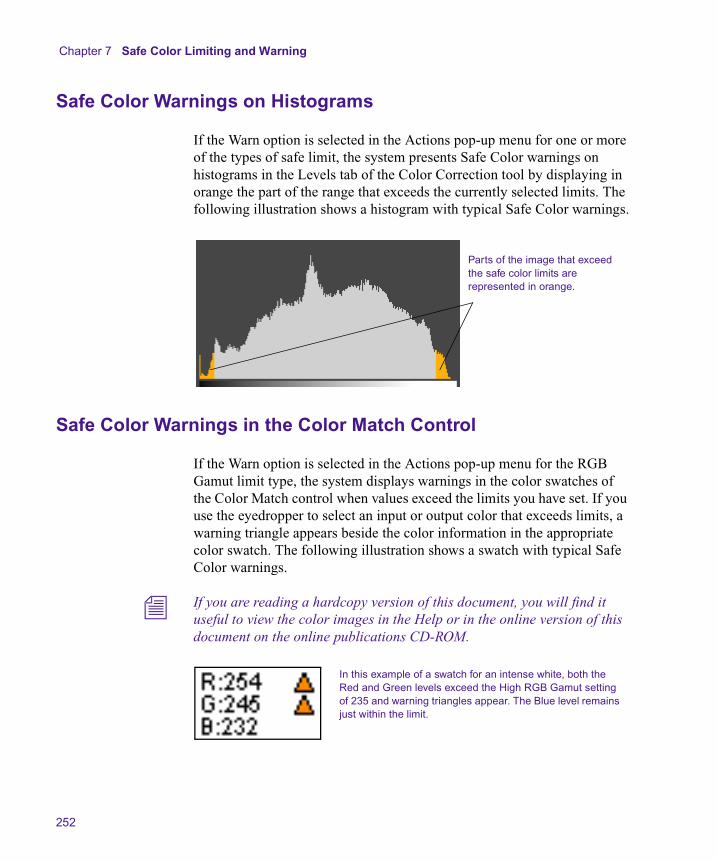
Chapter 7 Safe Color Limiting and Warning
252
Safe Color Warnings on Histograms
If the Warn option is selected in the Actions pop-up menu for one or more of the types of safe limit, the system presents Safe Color warnings on histograms in the Levels tab of the Color Correction tool by displaying in orange the part of the range that exceeds the currently selected limits. The following illustration shows a histogram with typical Safe Color warnings.
Safe Color Warnings in the Color Match Control
If the Warn option is selected in the Actions pop-up menu for the RGB Gamut limit type, the system displays warnings in the color swatches of the Color Match control when values exceed the limits you have set. If you use the eyedropper to select an input or output color that exceeds limits, a warning triangle appears beside the color information in the appropriate color swatch. The following illustration shows a swatch with typical Safe Color warnings.
n If you are reading a hardcopy version of this document, you will find it useful to view the color images in the Help or in the online version of this document on the online publications CD-ROM.
Parts of the image that exceed the safe color limits are represented in orange.
In this example of a swatch for an intense white, both the Red and Green levels exceed the High RGB Gamut setting of 235 and warning triangles appear. The Blue level remains just within the limit.

Understanding Safe Color Warnings
253
Safe Color Warnings in the Secondary Group Tab
If you select the Warn option in the Actions pop-up menu for the RGB Gamut limit type, the system displays a warning triangle above the Enable button of the Output Vector Saturation slider when the output saturation value exceeds the limits you have set. You can bring your secondary color correction within safe limits by adjusting the Output Vector Saturation slider until the warning triangle disappears. The following illustration shows the warning triangle with the Output Vector Saturation slider.
Adjusting Color Levels to Achieve Safe Limits
If some of your color levels exceed limits and you want to return them within limits by making manual adjustments, you can do so by adjusting the color correction controls in any combination. However, the simplest way to achieve safe limits by manual adjustment is by adjusting the appropriate output histograms in the Levels tab. This method allows you to see the histogram warnings as you adjust and does not disturb any of the more sensitive controls such as the Hue Offsets color wheels or the Curves graphs.
To achieve safe limits by adjusting output histograms:
1. Click the appropriate subdividing tab of the Levels tab.
The Levels tab includes a subdividing tab corresponding to each limit type — Composite, Luminance (Luma), Red, Green, and Blue.
2. If the limit is being exceeded at the low end, adjust the black point marker on the output histogram by dragging it to the right until the low end of the histogram no longer shows an orange area.
The associated indicator in the monitor no longer appears.
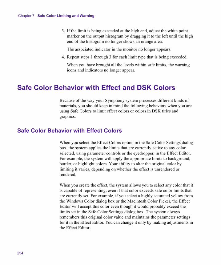
Chapter 7 Safe Color Limiting and Warning
254
3. If the limit is being exceeded at the high end, adjust the white point marker on the output histogram by dragging it to the left until the high end of the histogram no longer shows an orange area.
The associated indicator in the monitor no longer appears.
4. Repeat steps 1 through 3 for each limit type that is being exceeded.
When you have brought all the levels within safe limits, the warning icons and indicators no longer appear.
Safe Color Behavior with Effect and DSK Colors
Because of the way your Symphony system processes different kinds of materials, you should keep in mind the following behaviors when you are using Safe Colors to limit effect colors or colors in DSK titles and graphics.
Safe Color Behavior with Effect Colors
When you select the Effect Colors option in the Safe Color Settings dialog box, the system applies the limits that are currently active to any color selected, using parameter controls or the eyedropper, in the Effect Editor. For example, the system will apply the appropriate limits to background, border, or highlight colors. Your ability to alter the original color by limiting it varies, depending on whether the effect is unrendered or rendered.
When you create the effect, the system allows you to select any color that it is capable of representing, even if that color exceeds safe color limits that are currently set. For example, if you select a highly saturated yellow from the Windows Color dialog box or the Macintosh Color Picker, the Effect Editor will accept this color even though it would probably exceed the limits set in the Safe Color Settings dialog box. The system always remembers this original color value and maintains the parameter settings for it in the Effect Editor. You can change it only by making adjustments in the Effect Editor.
Safe Color Behavior with Effect and DSK Colors
255
When the unrendered effect is processed for playback, the system checks the effect color value against the limits set in the Safe Color Settings dialog box and, if appropriate, limits the color. If you change the limit values in the Safe Color Settings dialog box, the system checks the effect color value against the new limits.
As long as the effect remains unrendered, you can change the safe color limits as often as you wish. You can make them more permissive or more restrictive. The system applies the current safe color limits to the original color value when it processes the effect for playback.
If you render the effect, the system checks the original color value against the limits set in the Safe Color Settings dialog box and saves the resulting, limited color value in the precompute. The effect is now video material: when it is processed for playback, the system does not compare the Safe Color settings to the original value set in the Effect Editor. You can still limit the color value more (by setting more restrictive limits and selecting the Video option in the Safe Color Settings dialog box), but you cannot limit the color value less using safe colors. The only way to return to a more permissive color value is to adjust the effect in the Effect Editor, set more permissive safe color limits, and then rerender the effect.
The system behaves in the same way when it processes material for export. Effect colors are limited in accordance with the limits set in the Safe Color Settings dialog box at the time of export.
n Your system limits effect colors when it renders an effect or processes effect material for export, but it does not limit the video material that becomes part of the precompute or the exported file. If the video material in a rendered precompute exceeds limits and you play it in a sequence, you must have the appropriate Safe Color settings active if you want the video to be limited.

Chapter 7 Safe Color Limiting and Warning
256
Safe Color Behavior with DSK Titles and Graphics
The system limits a color that exceeds the current safe color limits in a DSK title or graphic at the time the title or graphic is created. (The exact point at which limiting takes places varies, depending on whether Safe Colors is selected or deselected in the Object menu.) To apply new limits to the colors in a DSK title or graphic, you must regenerate the title media.
If Safe Colors is selected in the Object menu, any color that you select in the Title tool when creating a title or graphic is limited immediately, based on the current settings in the Safe Color Settings dialog box. If the original color that you select exceeds limits, the system keeps no record of that original color and cannot return to it or compare to it.
If Safe Colors is deselected in the Object menu, the Title tool accepts any color that you select when creating a title or graphic, even if it exceeds the current settings in the Safe Color Settings dialog box. When the system creates media for that title (when the title is saved or when media is created for a Fast Save title), the original color value is compared to the current settings in the Safe Color Settings dialog box and the color is limited, if necessary. The system creates the DSK media with the limited color and keeps no record of the original color.
n If a situation arises in which you want to preserve a color in a DSK title or graphic that would exceed limits, make sure that Safe Colors is deselected in the Object menu and that DSK Titles and Graphics is deselected in the Safe Color Settings dialog box.
n If a DSK title or graphic is converted to an effect with video fill, that fill is treated like any other video material and is limited when the sequence is processed for playback. It is not limited at the time the title media is created.
Safe Color Limits with Waveform and Vectorscope Information
257
Safe Color Limits with Waveform and Vectorscope Information
To stay well within the limits of television transmitters, cable systems, satellite links, DVD encoders, and so on, broadcasters or distributors often issue safe color limits for video levels. Video levels outside safe color limits are generally known as “illegal.” Of course, no law is broken if you exceed the specified limits, but the program might be rejected on technical grounds or the image quality might suffer with further processing. If you know that your delivery master is a VHS tape that does not handle high chroma well, set some reasonable limits by yourself.
In Y (luma only) waveforms, reference white of 100% corresponds to a digital level of 235, an NTSC level of 100 IRE, and a PAL level of 700 mV. White excursions up to 108% are technically possible.
In Y (luma only) waveforms, reference black of 0% corresponds to a digital level of 16, an NTSC level of 7.5 IRE, and a PAL level of 0 mV. Black excursions down to –8% are technically possible.
n With both white and black levels, further signal processing (down the line from your Symphony system) might clip the peaks in your material. In addition, you might be required by delivery specifications to limit the white peaks to a lower level and the black peaks to a higher level.
Use Y Waveform to see the black and white levels of your image. Sometimes, particularly with white levels, keeping the white peaks within the 100% limit will not produce a pleasing level for the rest of the image. This is particularly common with backlit subjects, where the sky or a window is in the background and the lighting on the foreground is insufficient. In these cases, you might want to adjust for the foreground and leave the background too bright.
Chroma peaks are easiest to see on the Vectorscope monitor. The theoretical maximum is the circle around the outer edge, but to be safe you might like to keep vectors closer to the center than the 75% color bar squares.
Chapter 7 Safe Color Limiting and Warning
258
Saturated bright or dark colors might have very low or high luma values, together with a lot of chroma. Even if neither luma nor chroma alone is excessive, the combination can be illegal. For example, vivid yellow and cyan in an image can produce composite levels that are too high, and those from vivid blue might be unacceptably low. The YC Waveform is a good way to see how far these levels extend. In general, avoid levels above approximately 120 IRE or 850 mV, and those below –20 IRE or –200 mV.
n If you are producing a master for broadcast delivery, ask for delivery specifications. To ensure that you meet particular standards, use a legalizer such as the Safe Color Limiting feature of Symphony or a third-party AVX™ plug-in.
n These instruments do not measure analog outputs. If your Symphony system or other device uses analog connections, use an external waveform monitor to verify levels.
The Y Waveform, YC Waveform, and RGB Parade displays incorporate any safe color limits you have set. Table 22 describes the colors used to represent various conditions. “Legal” means the value is within the safe color limits. “Illegal” means the value is outside (either above or below) the safe color limits.
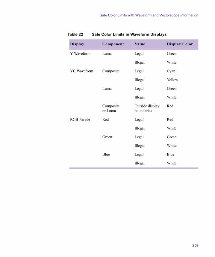
Safe Color Limits with Waveform and Vectorscope Information
259
Table 22 Safe Color Limits in Waveform Displays
Display Component Value Display Color
Y Waveform Luma Legal Green
Illegal White
YC Waveform Composite Legal Cyan
Illegal Yellow
Luma Legal Green
Illegal White
Composite or Luma
Outside display boundaries
Red
RGB Parade Red Legal Red
Illegal White
Green Legal Green
Illegal White
Blue Legal Blue
Illegal White
Chapter 7 Safe Color Limiting and Warning
260
Numerics10-bit units 6016:9 Video command (Color Correction shortcut
menu) 393 x 3 averaging
described 63using eyedropper option 81
3D effectsplayback with secondary color correction 179
8-bit units 60
AAchieving a final look
guidelines for 216Achieving shot-to-shot consistency
guidelines for 216Activating
monitors 32tabs in Color Correction tool 50
Adapting the original look of a shot 211Add to Selection button 169Adding
comments to color corrections 64Adjusting
input values in color vectors 162luminance ranges 108output values in color vectors 173
Applying an Effect Palette Color Correction effect 192
Automatic Color Correction effect templatesupdate behavior 67using 68
BBins
saving custom colors to 90saving effect templates in 70
Black point adjustmentsexamples of 119guidelines for 213
Blue tab (Levels group) 125Buckets 71Buttons
Add to Selection 169Color Correction Effect Template 70Color Correction Mode (Timeline) 30Color Selection 167Comments 65Correction Mode Settings 58Dual Split (Composer window) 36Edit Review (Command palette) 42Enable 55Go to Next Shot 41Go to Next Uncorrected Shot 41Go to Previous Shot 40
Index
A B C D E F G H I K L M N O P Q R S T U V W Y
Index
262
Go to Previous Uncorrected Shot 41in Color Correction tool 57in Composer window 40mapping to keyboard 40Play (Composer window) 41Play Loop (Command palette) 42Remove Effect 41Safe Colors 243Subtract from Selection 169Syringe 168Tab (Command palette) 52
CChannel Blending pane
considerations when using 115examples of settings in 116using 113
Channels groupdescribed 111function compared to Levels group 118
Channels tabconsiderations when blending channels 115examples of settings in 116making corrections in 112using the Channel Blending pane 113
Client monitorsplit-screen displays in 44switching display in 44using in Color Correction mode 44
Color adjustment tools in Symphony 26Color casts
correcting with color wheels 101Color correction
introduction to concepts 21Color Correction command (Timeline Fast menu)
75Color Correction effect (Effect Palette)
applying 192deleting 194
described 191saving as a template 194
Color Correction Effect Template button 70Color Correction effect templates
automatic template update behavior 67described 66tips for working with in the Effect Palette 73understanding save behavior 67using automatic templates 68
Color correction guidelinesadapting the original look 211correcting tonal range 213restoring an original look 210stages of correction 212
Color Correction modeComposer window in 32entering and exiting 30introduction to 22reviewing clips in context 42summary of display 31using Client monitor in 44
Color Correction Mode button (Timeline) 30Color Correction tool
activating tabs in 50associating tabs with Tab buttons 52buckets in 71buttons in 57Channels tab 112Composite tab (Levels group) 125, 132Controls tab (HSL group) 92customizing 58described 45displaying tabs using Tab buttons 53Enable buttons in 55hiding tabs in 59Highlights tab (HSL group) 93, 108Hue Offsets tab (HSL group) 97Luma Ranges tab (HSL group) 105Luma tab (Levels group) 125, 132Master tab (HSL group) 93

Index
263
Master tab (Levels group) 125Midtones tab (HSL group) 93, 108Red, Green, and Blue tabs (Levels group) 125Shadows tab (HSL group) 93, 108Source and Program tabs 47tabs in 46turning controls on or off in 55
Color Effect 26Color Match control
3 x 3 averaging of pixels, described 633 x 3 averaging of pixels, using 81and Curves tab 140and secondary color correction 174correcting with 81described 80example of use 88in Paint Effect modes for spot color correction
239in Spot Color Correction effect 236Match Type options for 83safe color warnings in 252using with syringe for secondary color
correction 175Color Selection buttons 167Color swatches
in Selected Vectors panel 160Color vectors
adjusting input values 162adjusting output values 173custom 153customizing display in color wheels 157described 153display in color wheels 153enabling 161hue range display in color wheels 155inverting 176isolating in an image 170repositioning in color wheels 163resetting 161
saturation range display in color wheels 156selecting 160standard 153using input sliders 163
Color wheelscorrecting color cast with 101customizing display of color vectors in 157described 99display of color vectors in 153display options for 63, 98in Secondary group 153moving crosshair pointers in 102repositioning color vectors in 163understanding 99
Color-corrected sequencesconverting to segment-only relationships 204flattening 204removing 206updating 196
Commentsadding to color corrections 64displaying in the Timeline 66
Comments button 65Comments command (Timeline Fast menu) 66Composer window
buttons in 40configuring monitors in 33controlling frame display in 43in Color Correction mode, described 32
Composite limits for broadcast 242Composite tab (Levels group) 125, 132Configuring monitors in Color Correction mode
33Control points
manipulating in Curves tab 137on Luma Ranges graphs 109
Controls tab (HSL group)controls described 95described 92
Index
264
Correcting colorgeneral procedure 78to achieve safe limits 253using the Channels tab 112using the Curves tab 137using the Hue Offsets tab 101using the Levels tab 124
Correcting color casts with color wheels 101Correction Mode Settings button 58Crosshair pointers in color wheels
described 99moving 102
Curve graphsmaking adjustments to 137
Curvesdescribed 130using to make Levels tab corrections 132
Curves groupSee Curves tab
Curves taband Color Match control 140examples of adjustments in 142making corrections in 137
Custom color vectors 153Custom colors
options for naming 62saving to bins 90
Customizing the Color Correction tool 58
DDecomposed and redigitized sequences
color correction workflow with 49Defining
segment relationships with IN and OUT points 62
units of measurement 60, 245Displaying
color correction information in Timeline 74comments in the Timeline 66
groups 50tracking information 33
DSK titles and graphics option in Safe Color Settings dialog box 256
Dual Split button (Composer window) 36Dual Split with Reference command (Color
Correction shortcut menu) 35, 38, 44
EEdit Review button (Command palette)
function in Color Correction mode 42Effect Colors option in Safe Color Settings dialog
box 254Effect Palette
automatic color correction effect templates in 68
Effect Palette Color Correction effectapplying 192deleting 194described 191saving as a template 194
Effect templates for color correctionautomatic template update behavior 67described 66understanding save behavior 67using automatic templates 68
EffectsColor 26Color Correction (Effect Palette) 191Paint 237Spot Color Correction 26, 232
Enable buttonsdescribed 55interactions between 56
Enablingcolor vectors 161
EnteringColor Correction mode 30
Index
265
Examplesblack point adjustments 119Channel Blending settings 116Color Correction merging 201correction with Color Match control 88correction with NaturalMatch 88Curves tab corrections 142gray point adjustments 122histograms 127Hue Offsets settings 103hue ranges in color vectors 155inverted images 177isolated images 171, 177Levels tab corrections 133Luma Ranges three-tone previews 109saturation ranges in color vectors 156softness adjustments (secondary color
correction) 165typical color correction problems 217
ExitingColor Correction mode 30
Eyedropper3 x 3 averaging of pixels, described 633 x 3 averaging of pixels, using 81and Color Selection buttons 169in Color Match control 82options for 63
FFiller 79Flatten Correction command (Color Correction
shortcut menu) 204Flattening color-corrected sequences 204Frame display
and locators 43controlling 43
GGo to Next Shot button 41Go to Next Uncorrected Shot button 41Go to Previous Shot button 40Go to Previous Uncorrected Shot button 41Graphics and safe colors 256Gray point adjustments
guidelines for 214Levels tab examples 122
Green tab (Levels group) 125Groups
Channels 111Curves 136described 24displaying 50HSL (Hue, Saturation, Luminance) 91interaction between 53Levels 117Secondary 150
Guidelines for color correctionachieving a final look 216achieving shot-to-shot consistency 216neutralizing color 214restoring an original look 210
HHide Video command (Color Correction shortcut
menu) 38Highlights tab (HSL group) 93, 108Histograms
described 126display options for 61examples of 127field-accurate display of 250safe color warnings on 252using controls 128
Index
266
HSL (Hue, Saturation, Luminance) group 91HSL sliders
described 95making adjustments with 94
Hue Offsets tab (HSL group)color wheel display options 63color wheels in 99described 97examples of settings for 103examples of use 103making corrections with 101
Hue ranges in color vectorsdisplay in color wheels 155
IImage updating options 63IN and OUT points
using to define segment relationships 62Input color vectors
adjusting 162sliders 163
Interaction between groups 53Invert Last Vector feature
described 159examples of images using 177
Inverting a color vector 176Isolate feature
described 159examples of images using 171, 177
Isolated imagesexamples of 171
Isolating color vectors in an image 170
KKeyboard
mapping buttons to 40
LLevels group
described 117function compared to Channels group 118
Levels tabCurves described 130examples of adjustments in 133examples of black point adjustments 119examples of gray point adjustments 122histogram display options 61histograms described 126making corrections in 124making curve adjustments 132understanding input and output adjustments in
119using histogram controls 128working with controls in 126
Locatorsusing to control frame display 43
Luma Ranges graphscontrol points on 109understanding 106
Luma Ranges tab (HSL group)adjusting luminance ranges in 108described 105three-tone previews in 109understanding graphs in 106
Luma tab (Levels group) 125, 132Luminance limits for broadcast 242Luminance ranges
adjusting 108
MMacintosh Color Picker 80Master tab (HSL group) 93Master tab (Levels group) 125

Index
267
Menu commands16:9 Video (Color Correction shortcut menu)
39Color Correction (Timeline Fast menu) 75Comments (Timeline Fast menu) 66Dual Split with Reference (Color Correction
shortcut menu) 35, 38, 44Flatten Correction 204Hide Video (Color Correction shortcut menu)
38Merge Correction 200Reference Current (Color Correction shortcut
menu) 35Remove Correction 206Safe Colors 256Update Correction 197
Merge Correction command (Color Correction shortcut menu) 200
Midtones tab (HSL group) 93, 108Millivolts (mVolts) 60Modes
options in Paint Effect for spot color correction 238
using in Paint Effect for spot color correction 237
Monitorsactivating 32configuring in Color Correction mode 33displaying 16:9 video in 39displaying reference frame in 35hiding video in 38isolating a color vector in 170navigating with buttons in 40safe color warnings in 249source menu in 34split-screen display in 36
mVolt (millivolt) units 60
NNaturalMatch
described 88example of use 88
Neutralizing colorguidelines for 214
OOutput color vectors
adjusting 173Overview of Color Correction mode 22
PPaint Effect
using for spot color correction 237Paint Effect modes
Color Match control in 239making spot color corrections with 237options for spot color correction 238
Parameters for Spot Color Correction effect 235Play button (Composer window) 41Play Loop button (Command palette) 42Playback
of color corrections 23Playback of secondary color corrections
overview 179with 3D effects 179with two-stream effects 180
Primary color correction 25Program side color correction
described 23selecting 47
Program tab 47
Index
268
QQuad Display
described 182in Source menu 36
RRed tab (Levels group) 125Reference Current command (Color Correction
shortcut menu) 35Reference frame
and split-screen display 35displaying in monitor 35
Relationships for color correctionchanging 47defining with IN and OUT points 62described 24listed 47using Source Clip Name 49
Remove Correction command (Color Correction shortcut menu) 206
Remove Effect button 41Removing
color corrections 206Rendering
color corrections 191effects with safe color limits 255
Resetting controls 55Restoring an original look 210Reviewing a color-corrected clip in context 42RGB color space 64, 115RGB gamut limit type
described 242RGB Histogram
and safe color limits 257described 183displaying 181in Source menu 36using 190
RGB Paradeand safe color limits 257, 259described 184displaying 181in Source menu 36using 190
RGB valuesdisplaying with the Color Match control 91reference black and white 60, 245
SSafe Colors
adjusting color to achieve safe limits 253and rendering of effect colors 255behavior with DSK titles and graphics 256behavior with Effect Colors option 254behavior with material for export 255defining units of measurement for 245described 27graphical view of settings 247overview of 242setting options for 243understanding warnings 249warnings in monitors 249warnings in the Color Match control 252warnings in the Secondary group tab 253warnings on histograms 252warnings with two-field media 250
Safe Colors button 243Safe Colors command (Object menu) 256Saturation ranges in color vectors
display in color wheels 156Secondary color correction
Add to Selection button 169Color Selection buttons 167described 26enabling color vectors 161examples of softness adjustments 165Invert Last Vector feature 159
Index
269
Isolate feature 159overview 150playback consideration with 179resetting color vectors 161Selected Vectors panel 159selecting color vectors 160Softness 165Subtract from Selection button 169Syringe button 168using Color Match control for 174vectors, described 153workflow for 151
Secondary groupsafe color warnings in 253
Selected Vectors panelcolor swatch update behavior 160described 159
Sequenceseffect of color corrections on 22flattening color-corrected 204removing color corrections from 206updating color-corrected 196
Shadows tab (HSL group) 93, 108Softness
examples of adjustments in secondary color correction 165
Source Clip Name relationship 49Source menu in monitors 34Source side color correction
described 23selecting 47
Source tab 47Split-screen display 36Spot Color Correction effect
Color Match control in 236described 26, 232examples of 232making corrections with 234parameters described 235
Stages of typical color correction 212
Standard color vectors 153Subtract from Selection button 169Switching display in Client monitor 44Symphony
color adjustment tools listed 26Syringe button
defining a vector with 168using with Color Match control for secondary
color correction 175
TTab buttons (Command palette) 52Tabs in Color Correction tool
activating 50associating with Tab buttons 52Channels 112Composite (Levels group) 125, 132Controls (HSL group) 92described 46displaying using Tab buttons 53hiding 59Highlights (HSL group) 93, 108Hue Offsets (HSL group) 97Luma (Levels group) 125, 132Luma Ranges (HSL group) 105Master (HSL group) 93Master (Levels group) 125Midtones (HSL group) 93Midtones tab (HSL group) 108Red, Green, and Blue (Levels group) 125Shadows (HSL group) 93, 108Source and Program 47
Templatessaving Effect Palette Color Correction effects
as 194Three-tone previews
examples of 109in Luma Ranges tab 109
Index
270
Timelinedisplaying color correction information in 74
Titles and safe colors 256Tonal range
guidelines for correcting 213Tracking information
displaying 33Transition effects
playback with secondary color correction 180Two-field media
safe color warnings with 250Two-stream effects
playback with secondary color correction 180
UUnderstanding safe color warnings 249Units of measurement
defining for Color Correction tool 60defining for Safe Colors feature 245
Update Correction command (Color Correction shortcut menu) 197
Updating color-corrected sequences 196
VVectors
in Secondary color correction 153Vectorscope
and safe color limits 257commands in Source menu 36described 185displaying 181using 190
Video Input tooland Color Correction 26
WWarnings
and two-field media 250in monitors 249in Safe Colors feature 249in the Color Match control 252in the Secondary group tab 253on histograms 252
Waveformcommands in Source menu 36displaying 181using 190
White point adjustmentsguidelines for 213
Windows Color dialog box 80Workflows
for color correction 78for secondary color correction 151
YY Waveform
and safe color limits 257, 259described 186displaying 181in Source menu 36using 190
YC Waveformand safe color limits 257, 259described 187displaying 181in Source menu 36using 190
Index
271
YCbCr Histogramand safe color limits 257described 188displaying 181in Source menu 36using 190
YCbCr Paradeand safe color limits 257described 189displaying 181in Source menu 36using 190
YCrCb color space 64, 115

Index
272