avery hardoll model bm250 bulk flowmetering system
TRANSCRIPT

5/6B/80A26 March 2004
12 Lyonpark Road, North Ryde NSW 2113 Australia
Cancellation
Certificate of Approval No 5/6B/80A
This is to certify that the approval for use for trade granted in respect of the
Avery Hardoll Model BM250 Bulk Flowmetering System
submitted by Gilbarco Australia Limited(formerly Gilbarco Aust. Ltd)20 Highgate StreetAuburn NSW 2144
has been cancelled in respect of new instruments as from 1 May 2004.
Signed by a person authorised under Regulation 60of the National Measurement Regulations 1999 toexercise the powers and functions of the Commissionunder this Regulation.


5160/0OA IO July 1996
National Standards Commission
TECHNICAL SCHEDULE No 5/6B/80A
Pattern: Avery Hardoll Model BM250 Bulk Flowmetering System.
Submittor: Gilbarco Aust. Ltd 12-38 Talavera Road North Ryde NSW 2113.
1. Description of Pattern
A bulk flowmetering system using an Avery Hardoll model BM250 flowmeter (Figure 1 and Table 1) which is approved for use with liquids having a viscosity range of 0.4 to 10 mm2/s at maximum and minimum flow rates of 1150 L/min and 115 L/min, respectively.
1.1 Pipeline Flowmetering System (Figure 2)
The system comprises:
(0 Tank
A supply tank, optionally with a low-liquid level device.
(ii) Pump
The pump may be fitted in either a suction lift or suction head (flooded suction) installation, i.e. either above or below (Figure 2) the liquid level in the supply tank, depending on the type of pump used.
Positive displacement type pumps may be fitted in either suction lift or suction head installations.
Centrifugal type pumps shall be fitted in suction head installations.
Submersible turbine type pumps may also be used, either alone or in systems which incorporate centrifugal type pumps fitted in suction lift installations.
If the pump is not for the exclusive use of the flowmeter the flow rate through the meter must stay within the appropriate flow rate range for all combinations of alternative uses of the pump.
(iii) Non-return Valve
A non-return valve between the pump and the meter or an arrangement of the components and piping to keep the system full of liquid at all times.
. . ../2

5/60/0OA IO July 1996
(iv) Gas Purger/Strainer
A gas purger/strainer assembly fitted as close as practical to the meter inlet. The gas purger is approved on the condition that the pump is operated under a positive suction head.
The gas purger/strainer assembly may be modified for use as a strainer only where the tank has automatic alarming of low-liquid level, or has a float-operated shut-off valve in the pump supply, or has other means to prevent gas entering the system.
w Meter
An Avery Hardoll model BM250 rotary vane, single capsule flowmeter (Figure 1). A back pressure valve may be incorporated in the outlet of the meter. Provision shall be made for a pressure gauge to be connected downstream of the meter.
(vi) Indicating System
The flowmetering system is fitted with either:
(4 An Avery Hardoll model Masterload bulk flowmeter control system as described in the documentation of NSC Approval No S262A - when the Masterload is fitted with a preset facility, the system must include a solenoid operated flow control valve; or
04 An Avery Hardoll mechanical calibrating assembly (Figure 1) and with either of the following:
. A Veeder-Root VR788700 zero start indicator; or
. A Veeder-Root VR789000 indicator/printer.
(vii) Transfer Device
A transfer device in the form of a positive shut-off component such as a manually or automatically-operated control valve located downstream of the meter with no intermediate outlet. A flow rate control valve may be fitted.
1.2 Sealing Provision
Provision is made for sealing the indicator or indicator/ticket printer, and the calibration device of the meter.
1.3 Verification/Certification Provision
Provision is made for a verification/certification mark to be applied.
. . ..I3
5/60/80A lOJuly
Technical Schedule No 5&U8OA Paae 3
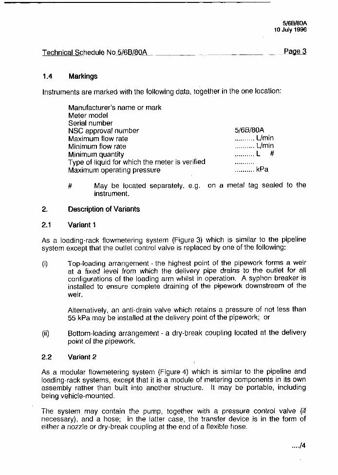
1.4 Markings
Instruments are marked with the following data, together in the one location:
Manufacturer’s name or mark Meter model Serial number NSC approval number Maximum flow rate Minimum flow rate Minimum quantity Type of liquid for which the meter is verified Maximum operating pressure
5/6B/80A . . . . . . . . . . L/min . . . . . . . . . . L/min . . . . . . . . . . L # .,........ . . . . . . . . . . kPa
# May be located separately, e.g. on a metal tag sealed to the instrument.
2. Description of Variants
2.1 Variant 1
As a loading-rack flowmetering system (Figure 3) which is similar to the pipeline system except that the outlet control valve is replaced by one of the following:
(0 Top-loading arrangement - the highest point of the pipework forms a weir at a fixed level from which the delivery pipe drains to the outlet for all configurations of the loading arm whilst in operation. A syphon breaker is installed to ensure complete draining of the pipework downstream of the weir.
Alternatively, an anti-drain valve which retains a pressure of not less than 55 kPa may be installed at the delivery point of the pipework; or
(ii) Bottom-loading arrangement - a dry-break coupling located at the delivery point of the pipework.
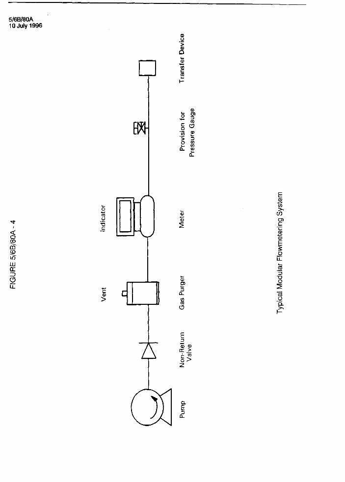
2.2 Variant 2
As a modular flowmetering system (Figure 4) which is similar to the pipeline and loading-rack systems, except that it is a module of metering components in its own assembly rather than built into another structure. It may be portable, including being vehicle-mounted.
The system may contain the pump, together with a pressure control valve (if necessary), and a hose; in the latter case, the transfer device is in the form of either a nozzle or dry-break coupling at the end of a flexible hose.
. . ../4
5/60/00A iOJuly1996
Technical Schedule No 5/68/80A
The pump is fitted in a suction head (flooded suction) installation, i.e. the pump is located lower than the minimum height of the liquid in the supply tank. A non-return valve is located between the pump and the meter, or the components and piping are arranged to keep the system full of liquid at all times.
Any nozzle used shall have an integral outlet control valve. If fitted with an integral anti-drain valve, the valve shall be immediately before the outlet control valve. A separate anti-drain valve may be fitted to the nozzle end of the hose if an integral anti-drain valve is not part of the nozzle. The anti-drain valve retaining pressure shall be not less than 55 kPa.
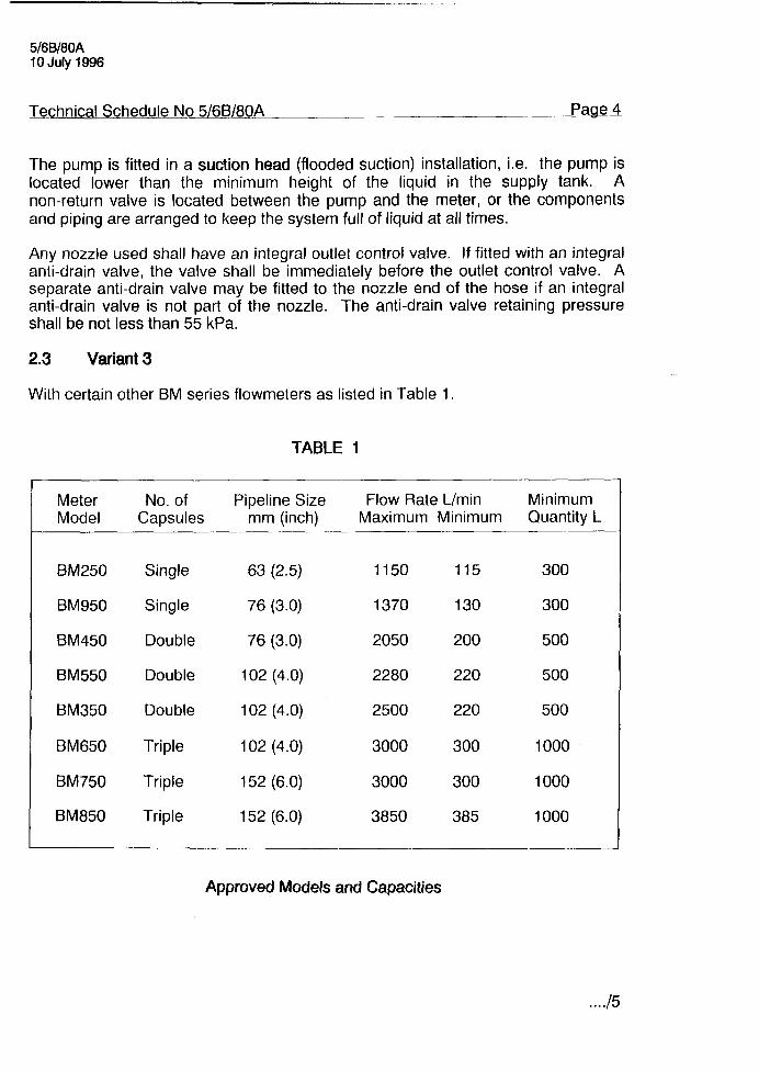
2.3 Variant 3
With certain other BM series flowmeters as listed in Table 1.
Meter No. of Model Capsules
BM250 Single
BM950 Single
BM450 Double
BM550 Double
BM350 Double
BM650 Triple
BM750 Triple
BM850 Triple
TABLE 1
Pipeline Size Flow Rate L/min Minimum mm (inch) Maximum Minimum Quantity L
63 (2.5) 1150 115 300
76 (3.0) 1370 130 300
76 (3.0) 2050 200 500
102 (4.0) 2280 220 500
102 (4.0) 2500 220 500
102 (4.0) 3000 300 1000
152 (6.0) 3000 300 1000
152 (6.0) 3850 385 1000
Approved Models and Capacities
. . ../5

5/60/00A lOJuly
TEST PROCEDURE
Instruments should be tested in accordance with any tests included in the approval documentation for the indicator, and in accordance with any relevant tests specified in the Inspector’s Handbook using the liquid with which they will be used and which is marked on the data plate.
Maximum Permissible Errors at Verification/Certification
The maximum permissible error applied during a verification test from normal flow rate to the minimum flow rate specified in the Certificate of Approval or Technical Schedule is +0.3%.
Where an instrument is fitted with a device to convert the indication of volume to volume at reference conditions, the maximum permissible error specified above is increased by 0.2%.
Reference conditions for petroleum liquids are specified in Australian Standard 2649 - 1983, Petroieum Liquids and Gases - Measurement - Standard Reference Conditions.


5/6B/EOA 10 July 1996
FIGURE 5/6B/80A - 1

5/60/8OA lOJuly

5/60/80A lOJuly
5/6B180A lOJuly 1996
b 5 0 E
E 8
