avc-1800 audio video controller - parasound · 4 important safety instructions save these...
TRANSCRIPT

O W N E R ' S M A N U A L
AVC-1800 Audio Video Controller
www.parasound.com
Re -EQTM

2
Table of Contents
Important Safety Instructions .............................................................................. 4
Introduction ......................................................................................................... 9
About this Manual ............................................................................................... 9
AVC-1800 Rear Panel Drawing ........................................................................... 10
AVC-1800 Front Panel Drawing........................................................................... 12
AVC-1800 Main Zone Remote Drawing .............................................................. 14
AVC-1800 Remote Zone Remote Drawing.......................................................... 16
Making Connections to Your AVC-1800............................................................... 17
AVC-1800 Input and Output Connection Drawing ............................................... 18
AVC-1800 Front Panel Controls .......................................................................... 22
AVC 1800 Remote Control Buttons ..................................................................... 25
Surround Processing Modes ............................................................................... 27
AVC-1800 On-screen Display.............................................................................. 29
Placement of Your Home Theater Speakers ........................................................ 29
Setting up your AVC 1800 ................................................................................... 32
Bass Management Settings ................................................................................ 32
Calibrating Channel Levels.................................................................................. 33
Programming the Learning Remote Control ........................................................ 34
Operating Your AVC-1800 ................................................................................... 36
Using the Tuner ................................................................................................... 36
Operating the Remote Zone ................................................................................ 38
Maintaining Your AVC-1800 ................................................................................. 38
In Case of Trouble ............................................................................................... 38
Blank Remote Control Drawings ......................................................................... 40
AVC-1800 Specifications ..................................................................................... 43
Record the following information for future reference:
Serial #_______________________ Date of Purchase__________________
Parasound Dealer__________________________________________________
Parasound Dealer's Phone Number____________________________________

3
AVC-1800 Audio Video Controller Features
• Full 24 bit Processing Using Crystal Semiconductor CS4926
• Dolby Digital Dolby Pro Logic, and DTS Decoding
• Three Burr-Brown PCM 1716 D to A Converters
• Reference Quality FM/AM Stereo Tuner with 29 Presets
• Digital Inputs and Surround Modes are Assignable to Sources
• Four Audio/Video Inputs with Composite and S-Video Connectors
• On-screen Display and Front Panel Indicators
• Illuminated, Eight Source Learning Remote Control
• Separate Rear Panel Infrared Input Connectors for Main and Zone
• Dual Zone Audio Controller With Separate 12 Volt DC Trigger
• 5.1 Analog Input for Future Format Compatability
Licensing Acknowledgements
Manufactured under license from Dolby Laboratories LicensingCorporation. “Dolby”, “Pro Logic”, and the double-D symbol aretrademarks of Dolby Laboratories Licensing Corporation. Copyright1992 Dolby Laboratories, Inc. All Rights Reserved
` Manufactured under license from Digital Theater Systems,Inc. US Pat. No. 5,451,942 and other worldwide patents issuedand pending. “DTS”, “DTS Digital Surround”, are trademarks ofDigital Theater Systems, Inc. Copyright 1996 Digital TheaterSystems, Inc. All Rights Reserved.
Manufactured under license from Lucasfilm Ltd. U.S. patent numbers5,043,970; 5,189,703; and 5,222,059.
Re -EQTM

4
Important Safety Instructions
Save these instructions for future use
This triangle alerts you to the dangerous voltages inside that may be a shock hazard.
This triangle alerts you to important operating and maintenance instructions in this manual.
ü Follow all instructions and warnings marked on the unit.
ü Always use with the correct line voltage. Refer to the manufacturer’s operating instructions for powerrequirements. Be advised that different operating voltages may require the use of a different line cord and/or attachment plug.
ü Do not install the unit in an unventilated rack, or directly above heat producing equipment such as poweramplifiers. Observe the maximum ambient operating temperature listed in the product specification.
ü Slots and opening on the case are provided for ventilation; to ensure reliable operation and prevent it fromoverheating, these openings must not be blocked or covered. Never push objects of any kind through theventilation slots. Never spill a liquid of any kind on the unit.
ü Never attach audio power amplifier outputs directly to any of the unit’s connectors.
ü To prevent shock or fire hazard, do not expose the unit to rain or moisture, or operate it where it will beexposed to water.
ü Do not attempt to operate the unit if it has been dropped, damaged, exposed to liquids, or if it exhibits adistinct change in performance indicating the need for service.
ü This unit should only be opened by qualified service personnel. Removing covers will expose you tohazardous voltages.
ü Adhere to all warnings on the unit and in the operating instructions.
ü Take precautions not to defeat the grounding or polarization of the units power cord.
ü Do not overload wall outlet, extension cords or integral convenience receptacles, as this can result in a riskof fire or electrical shock.
ü Route power supply cords so that they are not likely to be walked on or pinched by items placed on oragainst them, paying particular attention to cords at plugs, convenience receptacles, and the point at whichthey exit from the unit.
ü The unit should be cleaned only as recommended.
Communications Notice
This equipment generates and uses radio frequency energy and if not installed and used properly, that is, instrict accordance with the manufacturer’s instructions, may cause interference to radio and television reception.It has been type tested and found to comply with the limits for a Class B computing device in accordance withthe specifications in Subpart J of Part 15 of FCC Rules, which are designated to provide reasonable protectionagainst such interference in a residential installation. However, there is no guarantee that interference will notoccur in a particular installation. It this equipment does cause interference to radio or television reception,which can be determined by turning the equipment OFF and ON, the user is encouraged to try to correct theinterference by one or more of the following measures:
ü Reorient the television receiving antennaü Relocate the AVC-2500 away from the televisionü Plug the AVC-2500 into a different AC outlet so that the AVC-2500 and television are on different branch
circuits.
If necessary, the user should consult the dealer or an experienced radio/television technician for additionalsuggestions. The user may find the following booklet prepared by the Federal Communications Commissionhelpful: “How to identify and Resolve Radio/TV Interference Problems.” This booklet is available from theU.S. Government printing office, Washington, DC 20402, Stock No.004-000-00345-4.
Le présent appareil numénque n’ émet pan de bruits radioélectriques dépassant len limites applicables auxappareils numériques de la class B prescrites dans le Réglement sur le brouillage radloélectrique édicté par leministère des Communications du Canada.

5
Español
Instrucciones Importantes de Seguridad
Guarde esta instrucciones para uso posterior. Utilice siempre el voltaje correcto. Dirijase a las instrucciones deoperación del fabricante para obtener las especificaciones de potencia. Esté al tanto de que voltajes de operacióndistintos requleren el uso de cables y/o enchufes distintos.
No instale esta unidad en un estante sin ventilación, ni tampoco directamente encima de equipos que generen calortales como amplificadores de potencia. Fijese en las temperaturas ambientales máximas de operacidn que semencionan en las especificaciones del producto.
Las aperturas y ranuras del chasis sirven para proveer a ventilacion necesaria para operar Ia unidad con seguridady para prevenir sobrecalentamiento, y por lo tanto no pueden ser obstruidas o cubiertas. No introduzca objetos deningún tipo a través de las ranuras de ventilacón. y nunca deje caer ningún liquido sobre la unidad.
Nunca conecte ningún tipo de salida de amplificadores de sonido directamente a los conectores de la unidad.
Para prevenir descargas eléctricas o incendios, mantenga la unidad alejada de la lluvia, humedad o cualquier lugar
en el que pueda entrar en contacto con agua.
No trate de hacer funcionar la unidad si se ha caído, esta dañada, ha entrado en contacto con liquidos, o si notacualquier cambio brusco en su funcionamiento que indique la necesidad de hacerle un servicio de mantenimiento.
Esta unidad deberá ser abierta por personal calificado. Si usted quita las coberturas se expondrá a voltajes peligrosos.
Este triángulo que aparece en su componente le advierte soDre aexistenc;a dentro delchasis de voltajes peligrosos sin aislantes …voltajes que son lo suficientemente grandescomo para causar electrocución.
Este triángulo que aparece en su componente lo alerta sobre las instrucciones de operación ymantenimiento importantes que estan en los materiales de lectura que se incluyen.
Français
Instructions de Sûretè Importantes
Gardez ces instructions pour réference future.
Observez toutes les instructions et tous les avertisserments marqués sur l’appareil.
Branchez uniquements sur un réseau de tension indiquée. Consultez le manuel d’instruction du fabriquant pour lesspécifications de courant. N’oubliez pas que différentes tensions peuvent nécessiter l’utilisation de cables et/ou defiches de connexion différents.
N’installez pas l’appareil en un compartiment non-aéré ou directement audessus d’équipements générateurs dechaleur, tels qu’amplificateurs de courants, etc. Ne dépassez pas Ia température ambiante maximale defonctionnement indiquée dans les spécifications du produit.
Des fentes et ouvertures sont prévues dans le boîtier pour l’aération; Pour assurer le bon fonctionnement et pourprévenir l’échauffement, ces ouvertures ne doivent pas être couvertes ou bloquées. N’insérez pas d’objets dans lesfentes d’aération. Empêchez tout liquide de se répandre sur l’appareil.
Ne connectez jamais d’amplificateurs audio directement aux connecteurs de l’appareil.
Pour empêcher les chocs électriques et le danger d’incendie, évitez d’exposer l’appareil à Ia plule ou à l’humidité,et ne le mettez pas en marche en un endroit où iI serait exposé aux éclaboussures d’eau.
N’essayez pas de faire fonctionner l’appareil s’il est tombé à terre, a été endommangé, exposé à un liquide, ou sivous observez des différences nettes dans son fonctionnement, indiquant Ia nécessité de réparations.
Cet appareil ne dolt être ouvert que par un personnel de service qualifié. En enlevant les couvercles vous vousexposez à des tensions électriques dangereuses.
Ce triangle. sur votre appareil vous avertit de a présence de tension dangereuse, non-isolée àl’inténeur du boîtier.. une tension suffisante pour représenter un danger d’électrocution.
Ce triangle sur sur votre appareil vous invite de suivre d’importantes instructions d’utiiisation etd’entretien dans Ia documentation Iivrée avec le produit.

6
Deutsch
Wichtige Sicherheitsanweisungen
Heben Sie sich diese Sicherheitsanweisungen auch für später auf.
Befolgen Sie alle auf der Vorrichtung stehenden Anweisungen und Warnungen. Immer nur mit der richtigenSpannung verwenden! Die Gebrauchsanweisungen des Herstellers informieren Sie über die elektrischenAnforderungen Vergessen Sie nicht daß bei verschiedenen Betriebsspannungen ggf. auch verschiedeneLeitungskabel und/oder Verbindungsstecker zu verwenden sind.
Stellen Sie die Vorrichtung nicht in ein unbelüftetes Gestell oder unmittelbar uber wärmeerzeugende Gerätewie z.B. Tonverstärker. Halten Sie die In den Produktspezifikationen angegebene maximaleUmgebungstemperatur bei Betrieb ein.
Schlitze und Öffnungen im Gehause dienen der Belüfung; um verläßlichen Betrieb sicherzusteilen undÜberheizen zu vermeiden dürfen diese Öffnungen nich verstopft oder abgedeckt werden. Stecken Sie nieirgend einen Gegenstand durch die Belüftungsschlitze. Vergießen Sle keine Flüssigkeiten auf den Apparat.
Schließen Sie nie Tonverstärker unmittelbar an einen Anschluß des Apparates an.
Um elektrischen Schlag oder Feuer zu vermeiden, setzen Sie den Apparat weder Regen noch Feuchtigkeit ausund betreiben Sie ihn nicht dort wo Wasser eindringen könnte.
Versuchen Sie nicht den Apparat zu betreiben falls er fallen gelassen,beschädigt, oder Flüssigkeiten ausgesetztwurde, oder falls sich seineArbeitsweise derartändert daß daraus ein Bedarf nach Raparatur zu schließen ist.
Dieser Apparat sollte nur von qualifizierten Fachleuten geöffnet werden. Das Abnehmen von Abdeckungensetzt Sie gefährlichen Spannungen aus.
Dieses Dreieck auf Ihrem Apparat warnt Sie vor nicht-isolierter, gefahrlicher Spannung im Gehäusestark genug um eine Benührungsgefahr darzusteilen.
Dieses Dreieck auf Ihrem Apparat bedeutet daß wichtige Betriebsund Wartungsanweisungen in dermitgelieferten Dokumentation zu finden sind.
Italiano
Importanti norme di sicurezza
Conservare le presenti norme per l’utilizzo futuro.
Osservare tutte le istruzioni e le avvertenze apposte sull’unità.
Utilizzare esclusivamente con Ia tensione di rete correrta. Consuitare le istruzioni operative fornite dal fabbricanteper i dati riguardanti Ia tensione e l’assorbimento di corrente. Potrebbe essere necessario l’uso di cavi di retee/o di spine diverse a seconda della tensione utilizzata.
Non installare l’unita in uno scaffale privo di ventilazione oppure direttamente sopra una fonte di calore,come, ad esempio, un amplificatore. Non superare Ia temperatura ambientale massima di funzionamentoriportata nei dati tecnici del prodotto.
Le fessure e le altre aperture nella scatola servono alla ventilazione. Per un funzionamento affidabile, e perevitare un eventuale surriscaldamento. queste aperture non vanno ostruite o coperte in nessun modo. Evitarein tutti i casi di inserire oggetti di qualsiasi genere attraverso le fessure di ventilazione. Non versare mai delliquido di nessun tipo sull’unltà.
Evitare sempre di collegare le uscite dell’amplificatore audio direrttamente ai connettori dell’unità.
Per prevenire iI pericolo di folgorazione e di incendio non esporre l’unità alla pioggia o ad un’umidità eccessiva;evitare di adoperare l’unità dove potrebbe entrare in contatto con acqua.
Evitare di adoperare l’unità se Ia stessa è stata urtata violentemente, se ha subito un danno, se è stata espostaad un liquido o in caso di un evidente cambiamento delle prestazioni che indichi Ia necessità di un interventodi assistenza tecnica.
Ogni intervento sulI’unità va eseguito esclusivamente da personale qualificato. La rimozione della coperturacomporta l’esposizione al pericolo di folgorazione
II presente triangolo impresso sul componente avverte della presenza di tensioni pericolosenon isolate all’interno della copertura... tali tensioni rappresentano un pericolo di folgorazione
II presente triangolo impresso sul componente avverte l’utente della presenza nella allegata diimportanti istruzioni relative al funzionamento ed alla manutenzione.

7
Dansk
Vigtig information om sikkerhed
Gem denne Vejledning til senere brug.Folg alle anvisninger og advarsler pá apparatet.
Apparatet skal altid tilsluttes den korrekte spænding. Der henvises til brugsanvisningen, der indeholder specifikationerfor strømforsyning. Der gøres opmærksom pá, at ved varierende driftsspændinger kan det blive nødvendigt atbruge andre lednings- og/eller stiktyper.
Apparatet má ikke monteres i et kabinet uden ventilation eller lige over andet udstyr der udvikler varme, f.eks.forstærkere. Den maksimale omgivelsestemperatur ved drift, der stár opført i specifikationerne, skal overholdes.
Der er ventilationsábninger i kabinettet. For at sikre apparatets drift og hindre overophedning má disse ábningerikke blokeres eller tiIdækkes. Stik aldrig noget ind igennem ventilationsábningerne, og pas pá aldrig at spildenogen form for væske pá apparatet.
Udgangsstik fra audioforstærkere má aldrig sættes direkte i apparatet.
Apparatet má ikke udsættes for regn eller fugt og má ikke bruges i nærheden af vand for at undgá risiko forelektrisk stød og brand.
Apparatet má aldrig bruges, hvis det er blevet stødt, beskadiget eller vádt, eller hvis ændringer i ydelsen tyder pá,at det trænger til eftersyn.
Dette apparat má kun ábnes af fagfolk. Hvis dækslet tages af, udsættes man for livsfarlig højspænding.
Denne mærkat pá komponenten advarer om uisoleret, fartig spænding i aparatet... høj nok til at giveelektrisk stod.
Denne mærkat pá komponenten advarer om vigtig drifts- og vedligeholdsinfornation I den tuhorendetitteratur.
Svenska
Viktiga säkerhetsföreskrifter
Spara dessa föreskrifter för framtida bruk.
Följ alla anvisningar och Varningar som anges pá enheten.
Använd alltid rätt nätspänning. Se tiliverkarens bruksanvisningar för information om effektkrav. Märkväl, artandra matningsspänningar eventuellt kräver att en annan typs nätsladd och/eiler kontakt används.
Installera inte enheten i ett oventilerat stativ, eller direkt ovanför utrustningar som avger värme, t ex effekfförstärkare.Se till att omgivningens temperatur vid drift Inte överskrider det angivna värdet i produktspecifikationen.
Behallaren ar försedd med hál och bppningar för ventilering. För att garantera tillförlitlig funktion och förhindraöverhettning får dessa öppningar inte blockeras ellertackas. Inga förernal får skuffas in genom ventilationshalen.Inga vatskor får spilfas pa enheten.
Anslut aidrig audioeffekfförstarkarutgangar direkt till nagon av enhetens kontakter.
För art undvika elstot eller brandfara får enheten inte utsattas för regn eller fukt, eller användas pá ställen dar denblir vät.
Använd inte enheten om den har fallit i golvet, skadats, blivit vät. eller om dess prestanda förändrats märkbart.vilket kräver service.
Enheten får öppnas endast av behörig servicepersonal. Farliga spänningar blir tiligangliga när locken tas bort.
Denna triangel, som visas pá din komponent. varnar dig am en aisolerad fartig spänning inne ienheten. Den na spänning ar eventuetit sá hög att fara för eistöt föreligger.
Denna triangel, som visas pá din komponent, anger att viktiga bruksanvisningar ochserviceanvisningar ingár I dokumentationen frága.

8
Norsk
Viktig Informasjon om sikkerhet
Ta vare pá denne veiledningen for senere bruk.
Folg alle anvisningene og advarslene som er angitt pá apparatet. Apparatet skal alltid anvendes med korrektspenning. Produktbeskrivelsen inneholder spesifikasjoner for stromkrav. Vær oppmerksom pá at det ved ulikedriftsspenninger kan være nodvendig a bruke en annen ledning- og/ eller stopseltype.
Apparatet skal ikke monteres i skap uten ventilasjon, eller direkte over varmeproduserende utstyr, som foreksempel kraftforsterkere. Den maksimale romtemperaturen som står oppgitt i produktbeskrivelsen, skaloverholdes.
Apparatet er utstyrt med ventilasjonsápninger. For at apparatet skal være pálitelig I bruk og ikke overopphetes.má disse ápningene ikke blokkeres eller tildekkes. Stikk aldri noe inn I ventilasjonsápningene, og pass pá atdet aldri søles noen form for væske apparatet.Utgangsplugger fra audioforsterkere skal aldri koples direkte til apparatet.
Unnga brannfare og elektrisk stat ved å sørge for at apparatet ikke utsettes for regn eller fuktighet og ikkeanvendes i nærheten av vann. Apparatet skal ikke brukes hvis det har bliff utsatt for støt, er skadet eller bIittvått, eller hvis endringer i ytelsen tyder pá at det trenger service. Dette apparatet skal kun åpnes av fagfolk.Hvis dekselet fjernes, utsettes man for livsfarlig høyspenning.
Komponenten er merket med denne trekanten, som er en advarsei om at det finnes uisolert, farligspenning inne i kabinettet… hoy nok til á utgjore en fare for elektrisk støt.
Komponenten er merket med denne trekanten, som betyr at den tilhørende litteraturen inneholderviktige opplysninger om drift og vedlikehold.
Suomi
Tärkeitä turvallisuusohjeita
Säilytä nämä ohjeet tulevaa käyttöä varten.Seuraa kaikkia yksikköön merkittyjä ohjeita ja varoituksia.
Käytä aina oikeaa verkkojännitettä. Tehovaatimukset selviävät valmistajan käyttöohjeista. Huomaa, että enkäyttöjännitteet saattavat vaatia toisenialsen verkkojohdon ja/tai -pistokkeen käytön.
Älä asenna yksikköä telineeseen jossa ei ole tuuletusta. tai välittömästi lämpöä tuottavien laitteiden, esim,tehovahvistimien, yläpuolelle. Ympäristön lämpötila käytössä ei saa yiittää tuotespesifikaationmaksimilämpötilaa.
Kotelo on varustettu tuufetusreiillä ja -aukoilla. Luotettavan toiminnan vaimistamiseksi ja ylilämpenemisenvalttämiseksi näitä aukkoja ei saa sulkea tai peittää. Mitään esineitä el saa työntää tuuletusaukkoihin. Mitäännesteitä ei saa kaataa yksikköön.
Älä kytke audiotehovahvistimen lähtöjä suoraan mihinkään yksikön liittimeen.
Sähköiskun ja palovaaran välttämiseksi yksikkö ei saa olla sateessa tai kosteassa, eikä sitä saa käyttää märässäympäristössä.
Älä käytä yksikköä jos se on pudonnut, vaurioitunut, kostunut, tai jos sen suorituskyky on huomattavastimuuttunut, mikä vaatii huoltoa.
Yksikön saa avata vain laitteeseen perehtynyt huoitohenkilö. Kansien poisto altistaa sinut vaarallisille jännitteille.
Tämä kolmio, joka esiintyy komponentissasi. varoittaa sinua eristämattömän vaaraliisen jännitteenesiintymisestä yksikön sisällä. Tämä jännite saattaa olla riittävän korkea aiheuttamaansähköiskuvaaran.
Tämä kolmio, joka esiintyy komponentissasi, kertoo sinulle, että tässä tuotedokumentoinnissaesiintyy tärkeitä käyttö- ja ylläpitoohjeita.

9
Introduction
Congratulations on your purchase of this precision component and thank you for yourselection of Parasound. Your new AVC-1800 Audio Video Controller is designed to be theheart of your home theater system and to provide you with years of listening and viewingenjoyment.
Surround modes include Dolby Digital, Dolby Pro Logic, DTS, and two channel stereo. Youcan set up your AVC-1800 to detect the type of signal present at each input and automaticallydecode it based on how the source software was originally encoded. Your AVC-1800 alsohas discrete 5.1 channel analog inputs to accommodate the possibility of future formats.
The AVC-1800 has audio connections for independent remote zone operation. This featureallows you to route any of the analog audio sources connected to the AVC-1800 to both themain zone (Main) and a separate remote zone (Zone).
If you are in a hurry to have your AVC-1800 up and running and if you are already comfortablewith installing audio/video systems, refer to the drawings and descriptions on pages 10-16.However, since the AVC-1800 has extensive control capabilities, we strongly advise youtake the time to read these instructions thoroughly. You will need them to fully understandand appreciate its extensive capabilities.
About this Manual
The names of connectors and controls are italicized to help you find what you are lookingfor within in a particular section. On-screen and front panel display indications are in smallcapital letters. This manual was also written with the assumption that you have some priorexperience hooking up and installing audio/video systems.
Unpacking and Inspection
Carefully unpack your AVC-1800 Audio Video Controller and locate the enclosed accessories:
AVC-1800 Owner's ManualWarranty Card (North America only. Warranties in other regions provided by the respectiveauthorized Parasound Distributor)Universal remote control with 4 AAA batteriesDetachable AC cordFM Folded Dipole 300 Ω AntennaFM 300 ohm to 75 Ω balun matching transformerThreaded DIN to F type 75 Ω coax FM antenna adapterAM loop antenna
Be sure to carefully inspect the AVC-1800 for any signs of shipping damage. If you believeyou notice any, contact your Parasound Dealer immediately. Be sure to save both cartonsand the packing inserts for future transport and always pack the smaller carton into a largerprotective outer carton before shipment.
Placement of Your AVC-1800
Install your AVC-1800 near your source equipment so you can use the shortest possibleinterconnect cables. Keep your AVC-1800 out of direct sunlight because it could interferewith the remote control sensor. You should also keep the unit away from heat sources suchas hot air ducts radiators and moisture sources such as open windows.

10
CA
UT
ION
RIS
K O
F E
LEC
TR
IC S
HO
CK
DO
NO
T O
PE
N
Par
asou
nd
AV
C-1
800
Par
asou
nd P
rodu
cts,
Inc.
Aud
io V
ideo
Con
trol
ler
San
Fra
ncis
co,
CA
US
A
AC
120
V
50
/60H
z
1
"Dol
by","
Pro
Log
ic" a
nd th
e do
uble
-D s
ymbo
l are
trad
emar
ksof
Dol
by L
abor
ator
ies.
Con
fiden
tial U
npub
lishe
d W
orks
.
Man
ufac
ture
d un
der
licen
se fr
om D
olby
Lab
orat
orie
s.
All
Rig
hts
Res
erve
dC
opyr
ight
199
2-19
97 D
obly
Lab
orat
orie
s, In
c.
2 1
are
trad
emar
ks o
f Dig
ital T
heat
er S
yste
ms,
Inc.
issu
ed a
nd p
endi
ng. "
DT
S",
"D
TS
Dig
ital S
urro
und"
,
and
TH
X a
re r
egis
tere
dfr
om L
ucas
Film
Ltd
. Luc
asfil
m
All
Rig
hts
Res
erve
d.
Man
ufac
ture
d u
nder
lic
ense
Tra
dem
arks
of L
ucas
flim
Ltd
.
Cop
yrig
ht 1
996
Dig
ital T
heat
er S
yste
ms,
Inc.
Man
ufac
ture
d un
der
licen
se fr
om
Dig
ital T
heat
er S
yste
m, I
nc. U
S P
at.
No.
5,4
51,9
42 a
nd o
ther
wor
ld-w
ide
pate
nts
Pow
er C
onsu
mpt
ion:
32W
Per
sonn
el.
2D
o N
ot R
emov
e C
over
. No
Use
r
Ser
vici
ng T
o Q
ualif
ied
Ser
vice
Ser
vice
able
Par
ts In
side
. Ref
er
To
Pre
vent
Ele
ctric
Sho
ck,
CA
UT
ION
:
Dig
ital
Inpu
t
Opt
ical
Aud
io
DC
Trig
ger
Cen
ter
Zon
e Sur
roun
dMai
nZ
one
Coa
xial
L R
Cen
ter
Sur
roun
d
Sub
Mai
n Fro
nt
Fro
ntZ
one
Out
Out
In InV
ideo
1
Vid
eo 1
Mon
itor
Out
5.1
Ana
log
Inpu
t
Ext
Rem
ote
Out
Vid
eo 2
Out
In In
Vid
eo 2
Vid
eo 4
NT
SC
For
mat
Vid
eo 4
PA
L
Vid
eo 3
Vid
eo 3
Vid
eo
AM
GN
D
Bas
s M
anag
emen
t
Ant
enna
75
Sm
all
Off
Larg
eO
ffS
mal
l
Larg
e
Spe
aker
Con
figur
atio
n
Aud
io 2
L
Aud
io 3
Sm
all
Larg
e
Sur
roun
dL
& R
Cen
ter
Aud
io 1
Sub
300
Hz
LPF
S V
ideo
Mai
n O
utpu
tS
ubw
oofe
rO
utO
utIn
Out
InO
utA
udio
InA
udio
R
W
Re
-EQ
TM
3
15
1011
6
84
713
212
9

11
1. A
nten
na In
put C
onne
ctio
ns a
ndA
M A
nten
na C
lam
pC
on
ne
ct y
ou
r a
nte
nn
as
to t
he
se i
np
uts
.A
nten
nas
are
prov
ided
, bu
t yo
u ca
n us
eo
the
r a
nte
nn
as
for
imp
rove
d r
ece
ptio
n.
The
pro
vide
d A
M a
nten
na s
naps
into
the
AM
ant
enna
cla
mp.
2.
Bas
s M
anag
emen
t an
d V
ideo
For
mat
Sw
itche
sT
hese
sw
itche
s al
low
you
to c
onfig
ure
the
bass
man
agem
ent c
ircui
try
to m
atch
you
rsp
eake
r sy
stem
. The
vid
eo fo
rmat
sw
itch
sele
cts
NT
SC
or
PA
L fo
rmat
s fo
r pr
oper
vide
o sy
nchr
oniz
atio
n.
3.
Aud
io-O
nly
1-3
Ana
log
Inpu
tsan
d A
udio
Rec
ord
Out
put
All
thre
e a
na
log A
ud
io-o
nly
in
pu
ts a
reco
mpa
tible
with
typi
cal a
nalo
g lin
e le
vel
sour
ces.
Con
nect
the
left
and
right
ana
log
au
dio
ou
tpu
t o
f y
ou
r a
ud
io s
ou
rce
com
po
ne
nts
to
any
of
the
se a
ud
io-o
nly
inp
uts
. N
ote
th
at A
ud
io 1
ha
s a
se
t o
fR
eco
rd O
ut ja
cks.
Con
nect
the
lef
t an
dri
gh
t R
eco
rd o
utp
ut
jack
s o
f th
e A
VC
-1
80
0 t
o t
he
Re
cord
/In
pu
t ja
ck o
f yo
ur
anal
og r
ecor
ding
com
pone
nt.
4.
Aud
io/V
ideo
1-4
Ana
log
Inpu
tsan
d A
udio
/Vid
eo 1
-2 V
ideo
Rec
ord
Out
put J
acks
All
fou
r a
ud
io/v
ide
o a
na
log
in
pu
ts a
reco
mpa
tible
with
typi
cal a
nalo
g lin
e le
vel
sour
ces.
Con
nect
the
left
and
right
ana
log
audi
o ou
tput
of
your
aud
io/v
ideo
sou
rce
com
pone
nts
to th
ese In J
acks
. Vid
eo 1
and
2 al
so h
ave
a se
t of
ana
log
audi
o R
eco
rdO
ut j
acks
. C
onne
ct t
hese
out
puts
of
the
AVC
-180
0 to
the
Rec
ord/
Inpu
t ja
cks
ofyo
ur a
nalo
g re
cord
ing
com
pone
nt. V
ideo
1 an
d 2
also
hav
e a
set
of v
ideo
Rec
ord
Out
put j
acks
. Con
nect
thes
e ou
tput
s of
the
AVC
-180
0 to
the
Vid
eo R
ecor
d/In
put j
ack
of y
our r
ecor
ding
com
pone
nt s
uch
a V
CR
.
5. C
ompo
site
and
S-V
ideo
Inpu
tsE
ach
of t
he f
our A
ud
io/V
ide
o I
np
uts
has
both
com
posi
te a
nd S
-vid
eo c
onne
ctor
sw
ith
s
ep
ara
te
vid
eo
c
irc
uit
s
an
dam
plifi
ers.
The
AV
C-1
800
cann
ot c
onve
rtvi
deo
sign
als
from
S-V
ideo
to c
ompo
site
vide
o, o
r vi
ce v
ers
a. F
or e
xam
ple,
whe
nyo
u co
nnec
t a
vide
o si
gnal
to
one
of t
hefo
ur R
CA
com
posi
te R
CA
inpu
t jac
ks, t
hevi
deo
sign
al w
ill o
nly
be a
vaila
ble
thro
ugh
the
RC
A c
ompo
site
Mo
nito
r and
Re
cord
outp
ut ja
cks.
6. V
ideo
Mon
itor
Out
puts
Th
ere
are
bo
th c
om
po
site
an
d S
-Vid
eo
ou
tpu
t co
nn
ect
ion
s o
n t
he
AV
C-1
80
0.
Con
nect
the
Com
posi
te a
nd/o
r S
-Vid
eoM
on
ito
r O
ut
co
nn
ec
tors
to
th
eco
rre
spo
nd
ing
in
pu
t co
nn
ect
or
of
you
rm
onito
r or
pro
ject
or.
7. Z
one
Out
puts
Th
e Z
on
e a
ud
io o
utp
ut
con
ne
ctio
ns
pro
vid
e
ind
ep
en
de
nt
rem
ote
z
on
eop
erat
ion.
Con
nect
the
left
and
right
Z
one
au
dio
ou
tpu
t to
yo
ur
rem
ote
zo
ne
ampl
ifier
or
syst
em c
ontr
olle
r.
8. M
ain
Out
puts
Th
e A
VC
-18
00
pro
vid
es
ste
reo
ou
tpu
tp
air
s fo
r th
e l
eft
an
d r
igh
t fr
on
t a
nd
surr
ound
spe
aker
s, a
mon
aura
l out
put f
or
the
cent
er s
peak
er, a
nd a
mon
aura
l out
put
for
the
subw
oofe
r. C
onne
ct th
ese
outp
uts
to t
he in
puts
of
your
pow
er a
mpl
ifier
s.
9. 5
.1 A
nalo
g In
puts
Th
e 5
.1 A
na
log
Inp
ut co
nnec
tions
acc
ept
six
chan
nels
of
proc
esse
d an
alog
out
put
from
a D
VD
aud
io p
laye
r. C
onne
ct t
hesi
x d
iscr
ete
ou
tpu
ts o
f yo
ur
sou
rce
com
po
ne
nt
to t
he
co
rre
spo
nd
ing
5
.1A
nalo
g in
puts
of t
he A
VC
-180
0. Y
ou c
anal
so u
se t
he le
ft an
d rig
ht c
hann
el o
f th
e5.
1 an
alog
inp
uts
for
an a
dditi
onal
tw
och
anne
l ana
log
sour
ce.
Rea
r Pan
el C
onne
ctio
ns10
. In
frar
ed In
puts
Th
e M
ain
an
d Z
on
e e
xte
rna
l in
fra
red
in
pu
tsac
omm
odat
e in
frar
ed re
mot
e co
ntro
l ope
ratio
n fr
om th
em
ain
and
rem
ote
zone
s. C
onne
ct th
e ou
tput
of s
epar
ate
com
patib
le in
frar
ed r
epea
ter
syst
ems
to th
ese
inpu
ts.
11.
DC
Trig
gers
The
se DC
Trigg
er o
utpu
ts p
rovi
de a
+12
Vol
t DC
trig
ger
to a
ctiv
ate
equi
pmen
t suc
h as
pow
er a
mpl
ifier
s or
rela
ysin
eac
h zo
ne.
Con
nect
the
se o
utpu
ts t
o th
e D
C t
rigge
rin
put
of t
he c
ompo
nent
you
wan
t to
act
ivat
e.
12. D
igita
l Inp
uts
Your
AV
C-1
800
has
four
dig
ital i
nput
s: tw
o fib
er-o
ptic
Tosl
ink
inpu
ts a
nd t
wo
75 Ω C
oaxi
al i
nput
s. C
onne
ctth
e di
gita
l ou
tput
s of
you
r so
urce
equ
ipm
ent
to t
hese
inpu
ts.
13.
AC
Lin
e C
ord
Con
nect
ion
The
rea
r pa
nel
mou
nted
IE
C s
tand
ard
AC
rec
epta
cle
acce
pts
the
AC
cor
d su
pplie
d w
ith y
our A
VC
-180
0. P
lug
the
fe
ma
le e
nd
of
the
AC
co
rd f
irm
ly i
nto
th
e r
ea
rm
ount
ed A
C re
cept
acle
and
mak
e su
re th
at it
is p
rope
rlyse
ated
, th
en c
onne
ct t
he m
ale
end
to a
n un
inte
rrup
ted
AC
pow
er li
ne.

12
TUNE
D
STER
EOCH
MEMO
RY
MHz
Dig
ital
Sur
roun
d
Act
ive
Ton
eC
Del
ay
5.1
Ana
log
Aud
io 3
Zon
e
Re-
EQ
Ove
rload
Mut
e
Ana
log
5.1
2 C
h Coa
x1
2O
pt1
2
Aud
io 2
Vid
eo 4
Aud
io 1
Vid
eo 3
Vid
eo 2
Pro
Log
ic
Tun
ing
<>
Tun
erT
rebl
e
FM
/AM
Mon
o
Bas
sO
n-O
ff
Pre
set
AUTO FM
Vid
eo 1
A V
C -
1 8
0 0
A
u d
i o
V
i d
e o
C
o n
t r
o l l
e r
Re-
EQ
DT
S
Dol
by D
1
36
7
810
911
515
1412
134
2

13
Fro
nt P
anel
Con
trol
s
1. O
n-O
ff B
utto
nP
ress
the
On-
Off
butto
n to
turn
the
AVC
-180
0on
and
off.
Whe
n yo
u fir
st t
urn
the
unit
on,
the
fron
t pan
el d
ispl
ays
sho
w th
e la
st s
elec
ted
sour
ce in
put,
digi
tal i
nput
, sur
roun
d m
ode,
and
mas
ter v
olum
e le
vel.
The
tune
r fre
quen
cy a
ndst
atio
n pr
eset
num
bers
are
als
o di
spla
yed.
2. I
nfra
red
Rec
eive
rIn
frar
ed s
igna
ls f
rom
the
rem
ote
cont
rol
are
rece
ived
thro
ugh
the
IR r
ecei
ving
eye
for
the
mai
n zo
ne.
3. T
uner
Con
trol B
utto
ns
Mon
oP
ress
th
e M
on
o b
utt
on
to
re
ceiv
e w
ea
ker
stat
ions
and
red
uce
inte
rcha
nnel
noi
se.
FM
/AM
Thi
s bu
tton
allo
ws
you
to s
elec
t FM
and
AM
freq
uenc
y ba
nds.
Pre
set
The
pre
set b
utto
n sc
rolls
thro
ugh
all 2
9 pr
eset
stat
ions
tha
t yo
u m
ay s
tore
into
mem
ory
one
at
a t
ime
. P
rese
t n
um
be
rs w
ith
ou
t a
ctiv
ebr
oadc
ast
freq
uenc
ies
are
skip
ped
whe
n th
ep
rese
t but
ton
is p
ress
ed.
Tune
f e
f
e
f e
f
e
f e
But
tons
Whi
le in
the
Aut
o tu
ning
mod
e, p
ress
ing
this
butto
n no
rmal
ly a
dva
nces
to
the
next
act
ive
bro
ad
cast
fre
qu
en
cy.
In t
he
ma
nua
l tu
nin
gm
ode,
thes
e bu
ttons
sel
ect F
M fr
eque
ncie
s in
100
kHz
step
s (5
0 kH
z st
eps
for
expo
rt u
nits
)an
d A
M f
requ
enci
es in
10
kHz
step
s (9
kH
zfo
r ex
port
uni
ts)
4. T
one
Con
trols
and
Indi
cato
rT
he
Ba
ss c
on
tro
l b
oo
sts
an
d c
uts
lo
wfr
eq
ue
nci
es
+/-
10
dB
. T
he
T
reb
le c
on
tro
lbo
osts
and
cut
s hi
gh f
requ
enci
es +
/- 1
0 dB
.T
he To
ne in
dica
tor i
llum
inat
es w
hen
the
tone
circ
uitr
y is
act
ivat
ed w
ith t
he To
ne
but
ton.
The
Bas
s and
Tre
ble
cont
rols
onl
y af
fect
the
left
and
right
cha
nnel
s in
the
2 ch
anne
lm
ode.
5. I
nput
Sel
ectio
n B
utto
nsP
ress
thes
e bu
ttons
to s
elec
t the
Tun
er, A
udio
/V
ideo
inpu
ts 1
-4,
or A
udio
1-3
inpu
ts.
6. F
ront
Pan
el D
ispl
ay
Tune
r Dis
play
The
tune
r dis
play
indi
cate
s th
e cu
rren
t sta
tus
of
the
bu
ilt-i
n t
un
er.
Th
ese
in
dic
ati
on
sin
clud
e th
e F
M o
r AM
ban
d, fr
eque
ncy,
aut
oor
man
ual t
unin
g, s
igna
l str
engt
h an
d se
lect
edp
rese
t. T
his
disp
lay
rem
ains
on
even
if
the
tune
r is
not s
elec
ted
so y
ou k
now
wha
t sta
tion
you
will
be
on w
hen
you
sele
ct t
he t
uner
.
Sur
roun
d M
ode
Indi
cato
rsT
hese
ind
icat
ors
let
you
know
the
typ
e of
digi
tal b
itstr
eam
the
AVC
-180
0 ha
s de
tect
edan
d ho
w t
he s
igna
l is
bein
g pr
oces
sed.
Pro
Log
ic In
dica
tor
Thi
s in
dica
tor
illum
inat
es w
hen
you
sele
ctP
ro L
og
ic f
or
an
an
alo
g,
PC
M,
or
Do
lby
Dig
ital 2
/0 s
igna
ls.
5.1
Indi
cato
rT
his
in
dic
ato
r ill
um
ina
tes
wh
en
eve
r th
eAV
C-1
800
has
dete
cted
a D
olby
Dig
ital
orD
TS
5.1
cha
nnel
enc
oded
sig
nal.
Re-
Eq
Indi
cato
rT
his
indi
cato
r ill
umin
ates
whe
nR
e-E
qual
izat
ion
is a
ctiv
e.
2 C
h In
dica
tor
Thi
s in
dica
tor
illum
inat
es w
hen
the
AVC
-18
00 h
as b
een
set t
o tw
o-ch
anne
l ope
ratio
no
r it
de
tect
s a
Do
lby
Dig
ital
2/0
sig
na
l.In
com
ing
5.1
sign
als
are
dow
nmix
ed to
two
chan
nels
whe
n th
is is
on.
Volu
me
Leve
lT
his
indi
cato
r di
spla
ys t
he m
aste
r le
vel
ofth
e AV
C-1
800
from
-60
dB
to
+ 1
0 dB
.
Ana
log
Ove
rload
Indi
cato
rT
his
red
indi
cato
r w
ill il
lum
inat
e w
hen
the
inte
rna
l A
to D
co
nve
rte
rs a
re o
verl
oa
de
d.
Thi
s ca
n on
ly o
ccur
whi
le a
n an
alog
sou
rce
is o
verlo
adin
g th
e in
put.
Mut
e In
dica
tor
Thi
s in
dica
tor
light
s w
hen
the M
ute
bu
tto
nis
en
gag
ed
fro
m t
he
re
mo
te c
on
tro
l. T
his
LED
als
o lig
hts
whe
n th
e re
mot
e zo
ne is
on
whi
le th
e m
ain
zone
is o
ff.
Dig
ital a
nd A
nalo
g In
put I
ndic
ator
sT
hese
LE
Ds
light
whe
n th
e co
rres
pond
ing
dig
ital
(Op
tica
l 1
-2,
Co
ax
1-2
) o
r A
na
log
inpu
t is
sele
cted
with
the D
igita
l but
ton.
DT
S in
dica
tor
Thi
s in
dica
tor
illum
inat
es w
hen
the
AVC
-180
0 ha
s de
tect
ed a
DT
S b
itstr
eam
.
Dol
by D
igita
lT
he
Do
lby
Dig
ital
ind
ica
tor
illu
min
ate
sw
hen
the
AVC
-180
0 ha
s de
tect
ed a
Dol
byD
igita
l bits
trea
m.
7. C
ente
r Del
ay B
utto
nP
ress
this
but
ton
to s
elec
t del
ay ti
me
for
the
cent
er c
hann
el s
peak
er.
Eac
h pr
ess
of t
his
butt
on
in
cre
ase
s d
ela
y fr
om
on
e m
S t
o a
max
imum
of f
ive
mS
.
8. T
one
But
ton
Th
is b
utt
on
act
iva
tes
the
ba
ss a
nd
tre
ble
cont
rols
. The
TON
E in
dica
tor i
llum
inat
es w
hen
the
tone
con
trol
s ar
e ac
tive.
9. R
e-E
Q B
utto
nP
ress
the
Re-E
Q bu
tton
to e
ngag
e Lu
casf
ilmR
e-E
qual
iza
tion.
Pre
ss it
aga
in to
turn
it o
ff.
10.
Dig
ital B
utto
nT
he
Dig
ital
butt
on
se
lect
s th
e f
ou
r d
igita
lin
puts
or
the
anal
og in
put.
Whe
n yo
u se
lect
adi
gita
l in
put
to a
ccom
pany
one
of
the
inpu
tso
urce
s, th
e AV
C-1
800
will
rec
all t
hat d
igita
lin
put t
he n
ext t
ime
you
sele
ct th
e in
put s
ourc
e,th
ereb
y lin
king
the
m t
oget
her.
11.
Sur
roun
d B
utto
nB
y p
ress
ing
th
e Su
rro
un
d b
utt
on
, yo
u c
an
sele
ct b
etw
ee
n 5
.1,
Pro
Lo
gic
, a
nd
tw
och
anne
l. S
elec
ting
the
two-
chan
nel s
urro
und
mod
e w
ill d
ownm
ix a
5.1
cha
nnel
sig
nal.
12. 5
.1 A
nalo
g In
dica
tor
Th
is L
ED
lig
hts
wh
en
yo
u s
ele
ct t
he
5.1
anal
og in
put.
13. Z
one
Indi
cato
rsW
hen
the
rem
ote
zone
is o
n, th
e A
ctiv
e L
ED
light
s. T
he Z
one
LED
ligh
ts fo
r 5 s
econ
ds a
fter
a re
mot
e zo
ne c
omm
and
is is
sued
.
14. R
eset
But
ton
Acc
ess
Hol
eT
his
butto
n re
stor
es a
ll fa
ctor
y de
faul
ts a
ndc
lea
rs t
he
pro
gra
mm
ed
me
mo
ry.
Use
ato
othp
ick
or s
mal
l no
n-m
etal
too
l to
acc
ess
the
rese
t but
ton.
15. V
olum
e C
ontro
lT
his
cont
rol a
djus
ts th
e m
aste
r vol
ume
up a
nddo
wn
in 1
dB
incr
emen
ts. T
he v
olum
e di
spla
ych
ange
s to
sho
w t
he c
urre
nt v
olum
e le
vel.

14
EnterTune
Disc
Input Level
AV C DV D C DZONE
S AT
Display Digital
Surround
Trim
Vo l u m e
Tune
Vo l u m e
Mute
PresetPreset
T V V C R C B L
On
Off
MonoMem FM/AMMan
Tuner
Vid 1 Vid 2 Vid 3 Vid 4
Tone Delay
Aud 1 Aud 2 Aud 3
Light5.1 Cal
MAC 1 MAC 2 MAC 3 MAC 4
1 2 3 4 5
6 7 8 9 10
Re-EQ Dyn
2
7
20
10
14
8
11
13
4
6
19
21
22
5
23 24
25
3
1
15
16
12
9
Press the AVC button to control the main zone of the AVC-1800.
17
18

15
1. Programming Status LEDThis three-color LED flashes when programming infrared codesinto the learning remote control.
2. EIght Device ButtonsThe device buttons allow you to choose different “pages” tocontrol up to six additional components. Note: Press the AVCbutton first to control the main zone of the AVC-1800 and pressthe Zone button to operate the remote zone.
3. Display ButtonThe Display button activates the on-screen display to show theoperational status of the AVC-1800.
4. Digital ButtonThe Digital button allows you to select any of the four digitalinputs or the analog input.
5. Input Level ButtonsThese buttons adjust the signal level to the analog input circuitto prevent overload and distortion.
6. Surround ButtonPress the Surround button to select the Surround Processingmodes, including Pro Logic, 5.1, and two channel stereo.
7. On and Off ButtonsPress the On button to turn the AVC-1800 on; press the Offbutton to turn it off this function is differein for remote zoneoperation. See page 16.
8. Trim ButtonPress and release the Trim button to temporarily trim channellevels to suit your taste while watching a film or listening to arecording.
9. Volume ButtonThe Volume g and h buttons adjust the master volume up anddown in 1 dB steps. These buttons are also used for makingadjustments during trim and calibration operations.
10. Mute ButtonPress the Mute button to interrupt the audio signal from reachingthe Main analog output jacks of the AVC-1800.
11. Tune f f f f f ButtonWhen the tuner is active, pressing the Tune f button selectsthe previous available broadcast frequency.
12. Tune e e e e e ButtonWhen the tuner is active, pressing the Tune e button selectsthe next available broadcast frequency.
13. Preset f f f f f ButtonWhen the tuner is active, each press of the Preset f buttonselects the previous preset station.
14. Preset e e e e e ButtonWhen the tuner is active, each press of the Preset e buttonselects the next preset station.
15. Tone ButtonThis button activates the bass and treble controls. The tonecontrols are only available in the 2 channel mode.
16. Delay ButtonPress this button to select the amount of delay time for therear surround speakers.
17. Dynamic Range Control ButtonThe Dyn button engages a fixed degree of Dynamic RangeControl if there was any included in the bitstream during theencoding process.
18. Re-EQ ButtonPress the Re-EQ button to engage Lucasfilm Re-Equalizationfor any of the Surround modes.
19. Direct Access Source ButtonsThese buttons provide direct access to each of the seven inputsplus the tuner.
20. Tuner FunctionsThese buttons control the tuner functions of the AVC-1800including Memory, Mono, Manual Tuning, and AM/FM bandselection.
21. Numerical Preset Buttons 1-10, 11-20, 21-29Pressing any of these numerical preset buttons allows you toselect the radio station previously memorrized between 1and 10. To access preset numbers above 10, press thenumerical button again to add 10 to that preset number. Forexample, pressing 5 twice accesses preset 15 and pressingthree times accesses preset 25.
22. Macro ButtonsThe four macro buttons allow you to program a series ofcommands for one touch operation of multiple functions ofdifferent components such as turning on the AVC-1800 andyour DVD player and selecting play.
23. 5.1 ButtonThis button instructs the AVC-1800 to receive signals fromthe 5.1 Analog Input jacks. It does not select 5.1 digitalsurround decoding.
24. Light ButtonThe Light button illuminates all the remote control buttonsfor approximately 5 seconds.
25. Cal ButtonPress the Cal button to activate the calibration circuitry thatallows you to set the output levels of each channel of theAVC-1800.
The Learning Remote ControlMain Zone Control Buttons

16
EnterTune
Disc
AV C DV D C DZONE
S AT
Vo l u m e
Tune
Vo l u m e
Mute
PresetPreset
T V V C R C B L
On
MonoMem FM/AMMan
Tuner
Vid 1 Vid 2 Vid 3 Vid 4
Aud 1 Aud 2 Aud 3
Light
MAC 1 MAC 2 MAC 3 MAC 4
1 2 3 4 5
6 7 8 9 10
2
3
11
5
9
6
8
10
12
13
14
1
7
4
Press the Zone buttonto control the remote zone of the AVC-1800.
1. Programming Status LEDThis three-color LED flashes when programming infrared codesinto the learning remote control.
2. Device ButtonsThe device buttons allow you to choose different “pages” tocontrol up to six additional components. Note: Press the AVCbutton first to control the main zone of the AVC-1800 and pressthe Zone button to operate the remote zone.
3. On-Off ButtonPress the On button to turn the AVC-1800 on for the remotezone; press the On button again to turn it off. This operation isdifferent for the main zone.
4. Volume ButtonsThe Volume g and h buttons adjust the master volume up anddown in 1 dB steps.
5. Mute ButtonPress the Mute button to interrupt the audio signal from reachingthe zone output jacks of the AVC-1800.
6. Tune f f f f f ButtonWhen the tuner is activated, pressing the Tune f button selectsthe previous available broadcast frequency.
7. Tune e e e e e ButtonWhen the tuner is active, each press of the Preset e buttonselects the previous preset station.
8. Preset f f f f f ButtonWhen the tuner is active, each press of the Preset f buttonselects the previous preset station.
9. Preset e e e e e ButtonWhen the tuner is active, each press of the Preset e buttonselects the next preset station.
10. Direct Access Source ButtonsThese buttons provide direct access to each of the seven inputsand the tuner.
11. Tuner FunctionsThese buttons control the tuner functions of the AVC-1800including Memory, Mono, Manual Tuning, and AM/FM bandselection.
12. Numerical Preset Buttons 1-10, 11-20, 21-29Pressing any of these numerical preset buttons allows you toselect the radio station previously memorrized between 1 and10. To access preset numbers above 10, press the numericalbutton again to add 10 to that preset number. For example,pressing 5 twice accesses preset 15 and three times accessespreset 25.
The Learning Remote ControlRemote Zone Control
13. Macro ButtonsThe four macro buttons allow you to program a series ofcommands for one touch operation of multiple functions ofdifferent components such as turning on the AVC-1800 andyour DVD player and selecting play.
14. Light ButtonThe Light button illuminates all the remote control buttons forapproximately 5 seconds.

17
Optional Rack Mounting Kit
If you want to rack mount your AVC-1800, you will need to obtain the optional ParasoundRMK-3 Rack Mount Kit. When you install the RMK-3 onto the AVC-1800 and remove itsfour feet, the rack mounting brackets will occupy three rack spaces (5 1/4 inches high) in astandard 19” wide equipment rack. There will be slightly less than ¾” gap above the frontpanel when mounted in this fashion. Refer to the RMK-3 instructions for installationprocedures. Make certain to use the eight insulated shoulder washers included with theRMK-3 to prevent metal-to-metal contact between its brackets and your equipment rack andin order to prevent ground loops that could cause audible hum.
Making Connections to Your AVC-1800
Before making any connections to your AVC-1800, be sure to turn off the power to youramplifiers. When connecting cables to the AVC-1800, make sure there is no strain or tensionon any connections that could cause them to pull loose later.
Rear Panel Connections
To make installing the AVC-1800 and our instructions easier, we have organized discussionabout connections in a clockwise direction from the left side to the right side of the rearpanel and also by functional groups for analog audio, video, digital audio, antenna, infraredcontrol interface, and AC cord. References to specific connectors on the AVC-1800 areusually italicized.
Antenna Connections
You will not be able to receive any radio stations unless antennas for FM and AM bands areconnected. Following are options to connect FM and AM antennas to your AVC-1800.
FM Dipole Antenna
A standard FM “folded dipole” 300 ohm wire antenna with is included with your AVC-1800. This dipole antenna is adequate for most urban and suburban locations. Connect thespade lugs of the dipole antenna to the two screw terminals on the included small “balun”matching transformer. Carefully press the balun over the 75 Ω female connector of the rearpanel of your AVC-1800. Next, spread out the antenna and hang on the wall or the back ofthe equipment cabinet. Experiment with the direction and placement of the dipole antennato obtain the best reception.
75 Ohm Coaxial Antenna
The AVC-1800 has a standard DIN-type 75 Ω connector for a push-on coaxial FM antennaplugs. An adapter is included to accommodate the threaded F-type connectors that are usedin North America.
Outdoor Roof Antenna
For best reception and maximum noise rejection, we recommend the use of a high-qualityoutdoor FM antenna. The additional stations you can receive and the superior sound qualitywill make the extra effort worthwhile. Connect the outdoor antenna with a 75 Ω coaxialcable directly to the 75Ω FM Antenna Input of the AVC-1800. If you use 300 Ω twin lead,connect the two bare wire leads to the included “balun” adapter and press it onto the 75 Ωcoaxial FM antenna input connector.
Cable TV and Community Antenna
In many situations, you may be able to use the FM antenna output of a cable TV or acommunity antenna jack. These connect in the same fashion as an outdoor antenna.

18
Pla
y/O
ut
L R
DV
D P
laye
r
Rec
/In
Vid
eo C
asse
tte R
ecor
der
TV
Mon
itor
Left
Spe
aker
Cen
ter
Spe
aker
Rig
ht S
peak
erLe
ft S
urro
und
Rig
ht S
urro
und
Zon
e Le
ftZ
one
Rig
ht
Aud
io O
utD
igita
l Out
Coa
xial
Tos
link
L R S-V
ideo
Out
Com
posi
teV
ideo
Out
S-V
ideo
In
Com
posi
teV
ideo
InA
udio
Vid
eo
InOut
Aud
io
Out
put
L RCD
Pla
yer/
Tra
nspo
rt
Coa
xial
Dig
ital
Out
put
Aud
io
Pow
ered
Sub
woo
fer
Par
asou
nd A
VC
-180
0 In
put a
nd O
utpu
t Con
nect
ions
LR
LR
LSR
SC
ente
r
Y Cb
Cr
Zon
e A
mpl
ifier
or
Sys
tem
Con
trol
ler
Cas
sette
Dec
kA
mpl
ifier
Am
plifi
erA
mpl
ifier
CA
UT
ION
RIS
K O
F E
LEC
TR
IC S
HO
CK
DO
NO
T O
PE
N
Par
asou
nd
AV
C-1
800
Par
asou
nd P
rodu
cts,
Inc.
Aud
io V
ideo
Con
trol
ler
San
Fra
ncis
co,
CA
US
A
AC
120
V
50
/60H
z
1
"Dol
by","
Pro
Log
ic" a
nd th
e do
uble
-D s
ymbo
l are
trad
emar
ksof
Dol
by L
abor
ator
ies.
Con
fiden
tial U
npub
lishe
d W
orks
.
Man
ufac
ture
d un
der
licen
se fr
om D
olby
Lab
orat
orie
s.
All
Rig
hts
Res
erve
dC
opyr
ight
199
2-19
97 D
obly
Lab
orat
orie
s, In
c.
2 1
are
trad
emar
ks o
f Dig
ital T
heat
er S
yste
ms,
Inc.
issu
ed a
nd p
endi
ng. "
DT
S",
"D
TS
Dig
ital S
urro
und"
,
and
TH
X a
re r
egis
tere
dfr
om L
ucas
Film
Ltd
. Luc
asfil
m
All
Rig
hts
Res
erve
d.
Man
ufac
ture
d u
nder
lic
ense
Tra
dem
arks
of L
ucas
flim
Ltd
.
Cop
yrig
ht 1
996
Dig
ital T
heat
er S
yste
ms,
Inc.
Man
ufac
ture
d un
der
licen
se fr
om
Dig
ital T
heat
er S
yste
m, I
nc. U
S P
at.
No.
5,4
51,9
42 a
nd o
ther
wor
ld-w
ide
pate
nts
Pow
er C
onsu
mpt
ion:
32W
Per
sonn
el.
2D
o N
ot R
emov
e C
over
. No
Use
r
Ser
vici
ng T
o Q
ualif
ied
Ser
vice
Ser
vice
able
Par
ts In
side
. Ref
er
To
Pre
vent
Ele
ctric
Sho
ck,
CA
UT
ION
:
Dig
ital
Inpu
t
Opt
ical
Aud
io
DC
Trig
ger
Cen
ter
Zon
e Sur
roun
dMai
nZ
one
Coa
xial
L R
Cen
ter
Sur
roun
d
Sub
Mai
n Fro
nt
Fro
ntZ
one
Out
Out
In InV
ideo
1
Vid
eo 1
Mon
itor
Out
5.1
Ana
log
Inpu
t
Ext
Rem
ote
Out
Vid
eo 2
Out
In In
Vid
eo 2
Vid
eo 4
NT
SC
For
mat
Vid
eo 4
PA
L
Vid
eo 3
Vid
eo 3
Vid
eo
AM
GN
D
Bas
s M
anag
emen
t
Ant
enna
75
Sm
all
Off
Larg
eO
ffS
mal
l
Larg
e
Spe
aker
Con
figur
atio
n
Aud
io 2
L
Aud
io 3
Sm
all
Larg
e
Sur
roun
dL
& R
Cen
ter
Aud
io 1
Sub
300
Hz
LPF
S V
ideo
Mai
n O
utpu
tS
ubw
oofe
rO
utO
utIn
Out
InO
utA
udio
InA
udio
R
W
Re
-EQ
TM
Pla
y/O
ut
L R
Rec
/In

19
AM Antenna and Clamp
A molded plastic loop antenna is supplied with your AVC-1800. Connect the two wires ofthe AM loop antenna to the posts labeled AM and GND. Position the loop antenna for bestAM reception. If you are trying to pick up very distant stations, you may connect a singlelong wire to the AM terminal and a good earth ground to the GND terminal. Once you haveconnect the AM antenna, fasten it to the antenna clamp on the rear panel.
Bass Management Switches
Bass management is designed to assure overall balanced response by accommodating manydifferent types of speaker systems that may or may not be able to reproduce frequenciesbelow 80 Hz. The Bass Management switches allow you to configure your speakers toreproduce low frequencies below 80 Hz, or to filter out these frequencies and route them toyour front speakers or only to your subwoofer channels. The AVC-1800 has four toggleswitches, which you must set according to the characteristics of your speakers. Refer to thesetup section of this manual for more details on setting the bass management switches toaccommodate your home theater system.
NTSC/PAL Switch
This switch allows you to select the display default system to be for the NTSC or PAL videoformat. PAL is the video format in most European countries and NTSC is the predominantvideo format in other regions. If you select the incorrect format, the on-screen display willnot synchronize properly with your television and will look scrambled.
Input Connections
Analog Audio 1-3 Input Connections
The three audio-only analog inputs are compatible with typical analog line level sourcessuch as CD players, MiniDisc players, cassette decks, etc. Connect the left and right analogaudio outputs of your audio source components to these inputs. You can also “assign” any ofthe four Digital audio inputs to accompany any of these three Audio analog inputs.
Audio Only Record Output Connections
The audio signal from the source you select for the main zone is routed to the Record Outputconnectors of Audio 1. Connect the left and right play/output of your tape deck to the leftand right Audio 1 input connectors. Next, connect the left and right Record Output connectorsof your AVC-1800 to the left and right audio record/input connectors of your tape deck.
Analog Audio/Video 1-4 Input Connections
All four Audio/Video analog inputs are compatible with typical line level sources such asDVD players, videocassette recorders, satellite receivers, cable converter boxes, etc. Eachof the four Audio/Video inputs also switches an accompanying NTSC/PAL composite videoand an S-Video input. You can also assign any of the four Digital audio inputs to accompanythese four Audio/Video inputs. If you have a DVD player, be sure to connect its digitaloutput to one of the digital inputs of the AVC-1800 for digital surround decoding.
S-Video and Composite Video Input Connections
Each of the four Audio/Video inputs has both composite and S-Video connectors with separatevideo circuits and amplifiers. The AVC-1800 cannot convert video signals from S-video tocomposite video, or vice versa. For example, when you connect a video signal to one of thefour RCA composite RCA input jacks, the proper video signal will only be available throughthe RCA composite Monitor and Record output jacks. If you try to cross video platforms,the signal will be black and white and distorted.

20
Record and Playback Connections for Video 1 and Video 2
Video inputs 1 and 2 have audio and video record inputs so you can connect up to two audio/video recording components such as a video cassette recorder.
For audio, connect the left and right audio output connectors from the VCR you’ll use forrecording to the corresponding left and right audio inputs of either Video 1 or Video 2 labeledIn. Next, connect the left and right Out connectors of the AVC-1800 to the left and rightaudio input connectors of the VCR.
For video, connect the composite and/or S-Video output connectors from the VCR you willuse for recording to the Video 1 or 2 In connectors of the AVC-1800. Next, connect thecorresponding Video Out connectors of the AVC-1800 to the composite and or S-Videoinput connector of the VCR.
Zone Audio Output Connections
The AVC-1800 has analog stereo connections for independent remote zone operation. Thisfeature allows you to route any of the analog input sources connected to the AVC-1800 toboth the main zone (Main) and a separate remote zone (Zone). You can listen to different orthe same sources in the main and remote zones simultaneously. Connect the left and rightZone Audio Outputs to your remote zone power amplifier or system controller.
Composite and S-Video Monitor Output Connections
If your video monitor or projector is equipped with separate input connections and switchingfor composite video and S-Video, you can connect either or both video formats to the AVC-1800’s corresponding Composite Video or S-Video connectors. Note that the AVC-1800does not convert S-Video input signals to composite video output signals or composite videoto S-Video or vice versa.
Main External Remote Control
The Main External Remote allows for infrared remote control operation via a wired infraredrepeater system or system controller when infrared commands cannot directly reach thefront panel infrared receiver. The input connector accepts a standard 1/8-inch (3.5 mm) twoconductor mini plug. The tip is positive and the sleeve is negative. Your Authorized ParasoundDealer or Custom Installer can recommend a compatible infrared repeater system for theAVC-1800. Connect the output of an infrared repeater system to the Main IR input.
Zone External Remote Control
The Zone External IR allows for independent control of the AVC-1800 when routing audioto a remote zone. The input connector accepts a standard 1/8-inch (3.5 mm) two conductormini plug. The tip is positive and the sleeve is negative. Your Authorized Parasound Dealeror Custom Installer can recommend a compatible infrared repeater system for theAVC-1800. Connect the output of an infrared repeater system to the Zone IR input.
Main DC Trigger
This jack provides a +12 Volt DC trigger voltage to activate equipment that can be triggeredwith DC voltage such as power amplifiers, relays, motorized projection screen, fans, lights,or other components. Connect the Main DC Trigger output of the AVC-1800 to the DCinput of the component you want to activate. The DC trigger delivers up to up to 200 milliampsof current. The Main DC Trigger accepts a sub-mini (2.5 mm) two-conductor mini plug.The tip is positive and the sleeve is negative. You can program the AVC-1800 to activate theMain DC Trigger in response to turning on the AVC-1800 or to a button stroke on its remotecontrol. Refer to the Setup section for details on programming the Main DC Trigger.

21
Zone DC Trigger
This jack provides a +12 Volt DC trigger voltage to activate equipment that can be triggeredwith DC voltage such as power amplifiers or relays. Connect the Zone DC Trigger output ofthe AVC-1800 to the DC input of the component you want to activate. The DC triggerdelivers up to up to 200 milliamps of current. The Zone DC Trigger accepts a sub-mini (2.5mm) two-conductor mini plug. The tip is positive and the sleeve is negative. You can programthe AVC-1800 to activate the Zone DC Trigger in response to turning on the AVC-1800from a remote zone, or to a button stroke on its remote control. Refer to the Setup section fordetails on programming the Zone DC Trigger.
5.1 Analog Inputs
The 5.1 Analog Input jacks are designed to accept up to six channels of processed analogoutput from a component with discrete channels such as a DVD Audio or Super Audio CDplayer. With this advanced feature, the AVC-1800 will be able to accept future sources whosetechnology we cannot anticipate today. Connect the six discrete outputs of your sourcecomponent to the corresponding 5.1 Analog Input jacks of the AVC-1800. The master volumecontrol adjusts the level for the 5.1 analog inputs.
Main Output Connections
Front Left and Right Channel Outputs
Connect the Left and Right Front channel outputs of your AVC-1800 to two channels of amulti-channel amplifier that are connected to your main front left and right (L, R) speakers.
Center Channel Output
Connect the Center channel output of your AVC-1800 to an input of a multi-channel amplifierthat is connected to your center (C) speaker.
Left and Right Surround Channel Outputs
Connect the Left and Right Surround output jacks of your AVC-1800 to two channels of themulti-channel amplifier that are connected to your left and right surround (LS, RS) speakers.
Subwoofer Output Connection
When using a powered subwoofer with a built-in amplifier, connect the Subwoofer output ofyour AVC-1800 to the line input of your subwoofer. Make sure you switch off the crossoveron your subwoofer amp, because the 24 dB per octave low pass filter of the AVC-1800should be superior to it. If your sub does not have a bypass switch for its crossover, adjust itto its highest frequency to minimize “double filtering.”
Digital Audio Input Connections
Your AVC-1800 has four digital input connections: two Optical Toslink and two CoaxialRCA connectors. You may use the digital output of a source component in conjunction withits own analog output or that of another source component. Once you have connected thedigital output of your source component to one of the Digital Audio Inputs of the AVC-1800, you can choose a Digital input to be selected simultaneously with any of the fourAudio/Video or the three Audio-only sources. Refer to the setup instructions for DigitalAudio Input assignment procedures. For best results, use only cables intended for digitalsignal transmission.
Optical Toslink Input Connections
Each of the two optical Toslink inputs on the AVC-1800 labeled Optical 1 and 2 accept astandard S/PDIF digital bitstream from any CD player, DVD player, laserdisc player, DSSreceiver, or other digital component equipped with a Toslink optical output. Connect theoptical output of your digital source to either of the optical inputs using a Toslink cable.

22
Coaxial Digital Inputs
The two coaxial digital inputs on the AVC-1800 labeled Coaxial 1 and 2 accept a standardS/PDIF digital bitstream from any CD player, DVD player, DSS receiver, or other digitalcomponent equipped with a 75 Ω coaxial output. Connect the coaxial output of your digitalsource to either of the coaxial inputs using a digital interconnect cable designed for thisapplication.
AC Line Cord Connection
The rear panel mounted IEC standard AC receptacle accepts the AC cord supplied with yourAVC-1800. We recommend the use of an AC line filter to protect the AVC-1800 against linesurges and voltage fluctuations. Plug the female end of the AC cord firmly into the rearmounted AC receptacle and make sure that it is properly seated, then connect the male endto an uninterrupted AC power line.
AVC-1800 Front Panel Controls
We designed the AVC-1800 user interface to be simple and intuitive, so we avoidedunnecessary front panel controls and indicators that tend to make operation confusing. Duringsetup, you will have the opportunity to program typical functions and operations into memoryfor easy control of your AVC-1800.
On-Off Button
Press the On-Off button to turn the unit on and off. When you turn on the AVC-1800, itsfront panel display will show you the status of the settings that were made before the unitwas last turned off. The items displayed are the Input Source, Digital Input, Surround Mode,and Volume Level. The tuner frequency and preset number are also displayed regardless ofwhether the tuner is active.
Tuner Control Buttons
Mono Button
Press the Mono button to receive weaker stations and reduce interchannel noise.
FM/AM Button
This button allows you to select FM or AM frequency bands.
Preset Button
The preset button scrolls through all 29 preset stations that were stored into memory one ata time. Preset numbers without active broadcast frequencies are skipped when the presetbutton is pressed.
Tune f ef ef ef ef e Buttons
While in the Auto tuning mode, pressing this button normally advances to the next activebroadcast frequency. In the manual tuning mode, these buttons select FM frequencies in 100kHz steps (50 kHz steps for export units) and AM frequencies in 10 kHz steps (9 kHz forexport units).

23
Tone Controls and Indicator
The Bass control boosts and cuts low frequencies +/- 10 dB. The Treble control boosts andcuts high frequencies +/- 10 dB. The Tone indicator illuminates when the tone circuitry isactivated with the Tone button. The Bass and Treble controls only affect the left and rightchannels in the 2 channel mode.
Input Selection Buttons
Press these buttons to select the Tuner, Audio/Video inputs 1-4, or Audio 1-3 inputs.
Front Panel Display
Tuner Display
The tuner display indicates the current status of the built-in tuner. These indications includethe FM or AM band, frequency, auto or manual tuning, signal strength and selected preset.This display remains on even if the tuner is not selected so you know what station will be onwhen you select the tuner.
Surround Mode Indicators
These indicators let you know the type of digital bitstream the AVC-1800 has detected andhow the signal is being processed.
Pro Logic Indicator
This indicator illuminates when you select Pro Logic for an analog, PCM, or Dolby Digital2/0 signals.
5.1 Indicator
This indicator illuminates whenever the AVC-1800 has detected a digital 5.1 channel encodedsignal.
2 Ch Indicator
This indicator illuminates when the AVC-1800 has been set to two-channel operation or itdetects a Dolby Digital 2/0 signal. Incoming 5.1 signals are downmixed to two channelswhen this is on.
Volume Level
This indicator displays the master level of the AVC-1800 from -60 dB to + 10 dB.
Analog Overload Indicator
This red indicator will illuminate when the internal A to D converters are overloaded. Thiscan only occur while an analog source is overloading the input.

24
Mute Indicator
This indicator lights when the Mute button is engaged from the remote control. This LEDalso lights when the remote zone is on while the main zone is off.
Digital and Analog Input Indicators
These indicators illuminate when the corresponding digital (Optical 1-2, Coax 1-2) or Analoginput is selected with the Digital button.
DTS Indicator
This indicator illuminates when the AVC-1800 has detected a DTS bitstream.
Dolby Digital Indicator
The Dolby Digital indicator illuminates when the AVC-1800 has detected a Dolby Digitalbitstream.
Center Delay Button
Press this button to select delay time for the center channel speaker. Each press of thisbutton increases delay from one mS to a maximum of five mS.
Tone Button
This button activates the bass and treble controls. The TONE indicator illuminates when thetone controls are active.
Re-EQ Button
Press the Re-EQ button to engage Lucasfilm Re-Equalization. Press it again to turn it off.
Digital Button
The Digital button selects the four digital inputs or the analog input. When you select adigital input to accompany one of the input sources, the AVC-1800 will recall that digitalinput the next time you select the input source thereby linking them together.
Surround Button
By pressing the Surround button, you can select between 5.1, Pro Logic, and two channel.Selecting the two-channel surround mode will downmix a 5.1 channel signal.
5.1 Analog Indicator
This LED lights when you select the 5.1 analog input from the remote control.
Zone Indicators
When the remote zone is on, the Active LED lights. The ZONE LED lights for 5 seconds aftera remote zone command is issued.

25
Reset Button Access Hole
This button restores all factory defaults and clears the programmed memory. Use a toothpickor other small non-metal tool to access the reset button.
Volume Control
This knob adjusts the master volume up and down in 1 dB increments. The volume displaychanges to show the current volume level.
AVC 1800 Remote Control Buttons
Device Buttons
The device buttons allow you to choose different “pages” to control up to six additionalcomponents. Note: First press the AVC button to control the AVC-1800 and press theZone button to operate the remote zone.
Display
The Display button activates the on-screen display to show the operational status of theAVC-1800. There are two levels of on-screen display. The first press of the button showsinput status, the second press of the button displays the channel levels and decoding status,and the third press turns the display off.
Input Level f e f e f e f e f e Buttons
These buttons set the signal level to the analog input circuit to prevent overload. If theoverload LED illuminates, you need to turn the input level down. Press the Input e buttonto increase the level to the analog input circuitry. Press the Input f button to decrease thelevel to the analog circuitry.
Digital Button
The Digital button allows you select any of the four digital inputs or the analog input.
Surround Button
The Surround button allows you to cycle in either direction to select the Surround Processingmodes including Pro Logic, 5.1, and two channel stereo.
On and Off Buttons
Press the On button to turn the AVC-1800 on; press the Off button to turn it off. Separate onand off commands for ease of use while setting up macros or programming external systemcontrollers. This operation is different for the remote zone.
Trim Button
Press and release the Trim button to temporarily trim the volume levels of individual channelslevels to suit your taste while listening to a particular film soundtrack or recording.
Volume g hg hg hg hg h Buttons
The Volume g and h buttons adjust the master volume up and down in 1 dB steps. Thesebuttons are also used for making adjustments during Trim and calibration (Cal) operations.

26
Mute
Press the Mute button to interrupt the audio signal from reaching the Main analog outputjacks of the AVC-1800. The Mute button does not affect the Record Output jacks or the ZoneOutput jacks (unless Zone is presently under control).
Tune f e f e f e f e f e Buttons
While in the Auto tuning mode, pressing this button normally advances to the next activebroadcast frequency. In the manual tuning mode, these buttons select FM frequencies in 100kHz steps (50 kHz steps for export units) and AM frequencies in 10 kHz steps (9 kHz forexport units.
Preset f f f f f Button
Press the Preset f button to select the previous preset station.
Preset e e e e e Button
Press the Preset e button to select the next preset station.
Tone Button
This button activates the bass and treble controls in the two channel mode. When the tonecontrols are active, the TONE indicator illuminates.
Delay Button
Press this button to select the amount of delay time for the surround speakers. Each press ofthis button increases surround delay time by 5 milliseconds to a maximum of 15 milliseconds.
Re-EQ Button
Press the Re-EQ button to engage and disengage Lucasfilm Re-Equalization for any Surroundmode. Re-Eq restores the correct tonal balance of a film soundtrack designed for playbackin large movie theaters in a relatively small home theater environment. It is not desirable fornormal music playback and should be turned off.
Dynamic Range Control Button
The Dyn button engages a fixed degree of Dynamic Range Compression that is available ifthe DVD you are playing includes it in its Dolby Digital bitstream. This feature allowssoundtracks with a wide dynamic range to maintain clear audibility even at low levels.
Direct Access Source Buttons
The source buttons provide direct access to each of the eight inputs of the AVC-1800. Thesource buttons are labeled Aud (Audio) 1-3, Vid (Video) 1-4, and Tuner.
Tuner Functions
Memory Button
This button stores the selected broadcast frequency into memory. Select the frequency youwant to store into preset, press Mem, then the desired preset number.
Mono
Press the Mono button to receive weaker stations and reduce interchannel noise. Mono onlyworks for the tuner. It does not for work for other inputs.

27
Manual Button
While in the Auto tuning mode, pressing the Tuning f e buttons normally selects the previousor next active broadcast frequency. Press the Man button to select the manual tuning mode,then the Tuning f e buttons selects FM frequencies in 100 kHz steps (50 kHz steps forexport units) and AM frequencies in 10 kHz steps (9 kHz for export units)
FM/AM Button
The FM/AM button selects FM and AM frequency bands while the tuner is active.
Numerical Preset Buttons 1-10, 11-21, 21-29
Pressing any of these numerical preset buttons allows you to select the radio station previouslymemorized between 1 and 10. To access preset numbers above 10, press the numerical buttonagain to add 10 to that preset number. For example, pressing 5 twice accesses preset 15 andthree times accesses preset 25.
Macro Buttons
The four Macro buttons allow you to program a series of commands for one touch control ofdifferent components such as turning on your AVC-1800 and DVD player and selecting play.
5.1 Analog Button
This button instructs the AVC-1800 to receive signals from the 5.1 Analog Input jacks wherethe analog output from a DVD player or other component with discrete outputs may beconnected.
Light Button
The Light button illuminates all the remote control buttons for approximately 5 seconds. Theillumination makes it easier to see the buttons in a darkened room.
Cal Button
Press and hold the Cal button to activate the calibration circuitry to set the levels of eachchannel of the AVC-1800. Refer to setup section of this manual for details.
Surround Processing Modes
Digital based audio/video source components transmit their audio signals in either Analog,Pulse Code Modulation (PCM), Dolby Digital, or DTS. Your AVC-1800 automatically detectsthe type of digital signal present at the chosen digital input. The signal is then decoded basedupon the surround processing mode you have selected for the audio/video (1-4) or audio only(1-3) input. Following is how the AVC-1800 decodes the incoming signal:
Mode Encoded Signal Decoding Format Active Channels On-screen Indication
5.1 Ch 5.1 ch Dolby Digital 5.1 ch Dolby Digital L, C, R, LS, RS, Sub Dolby Digital 3/2./15.1 ch DTS 5.1 ch. DTS L, C, R, LS, RS, Sub DTS Digital 3/2/.1
Pro -Logic 2 ch Dolby Digital Pro Logic surround L, C, R, Mono Surround, Sub Digital Pro Logic
2 ch analog input Pro Logic surround L, C, R, Mono Surround, Sub Analog Pro Logic
2 Ch 5.1 ch Dolby Digital DD 2 channel downmix L, R, Sub Dolby Digital 2 Ch2 ch Dolby Digital DD Stereo L, R, Sub Dolby Digital 2 ChDTS DTS 2 channel downmix L, R, Sub DTS 2 ChPCM 2 channel stereo L, R, Sub 2 ChAnalog 2 channel stereo L, R, Sub 2 Ch

28
Dolby Digital
Dolby Digital delivers up to six totally separate (discrete) channels of sound, also known as5.1. Like Dolby Surround Pro Logic, it includes Left, Center and Right channels across thefront of the room. The sixth channel, the Low Frequency Effects channel, contains additionalbass information to maximize the impact of scenes with special effects such as explosions,crashes, etc. The AVC-1800 LFE channel frequency response is 3 Hz to 120 Hz.
Dolby Digital Encoding Indication
Dolby has established a system to let you know how the original material was encoded. Itconsists of three numbers separated with forward slashes. The first number represents thefront channels, the second number represents the rear channels, and the third number representsthe LFE. This encoding information is shown in the on screen display. Following are examplesof digital bitstream encoding:
Indication Active channels
3/2/.1 (5.1) Three discrete channels in the front, two in the rear and LFE3/1 Three discrete channels in the front, mono rear surrounds, and no LFE2/1 Two discrete channels in the front, mono rear surrounds, and no LFE2/0 Two discrete channels in the front and no surrounds or LFE
Pro Logic
If the incoming digital signal is encoded in Dolby Digital Surround Pro Logic, the AVC-1800 automatically selects Pro Logic. However, you should use the Surround key to selectPro Logic, for analog and PCM signals if you want the AVC-1800 to decode a stereo signalinto Dolby Surround Pro Logic.
DTS
Like Dolby Digital, DTS Digital Surround is an encode/decode system that delivers two orsix channels (5.1) of audio for soundtracks and multi-channel recordings. Digital TheaterSurround (DTS) surround formatted DVDs must be played back on DVD players that areequipped with DTS output capability.
Two-channel PCM
Digitally encoded PCM material is found on the digital outputs of compact discs and laserdiscs. If you the select two channel surround mode, the AVC-1800 plays back two channelstereo with sub (depending on bass management configuration). If you select Pro Logic, theAVC-1800 decodes the PCM signal into Pro Logic. If the material was not encoded in ProLogic, you may still enjoy the resulting surround sound effects.
Analog Audio
Two-channel analog material is typically found on VCR tapes and the analog outputs of CDPlayers, DVD players and cassette decks. If you the select two channel surround mode, theAVC-1800 plays back two channel stereo. If you select Pro Logic, the AVC-1800 will decodethe PCM signal using Pro Logic. Results may vary between different analog recordings.
Re-EQ
By pressing the Re-EQ button on the remote control or on the front panel, you can activatethe advanced Lucasfilm Re-EQ enhancement. Lucasfilm engineers developed a patentedfrequency contouring equalization to accurately translate the sound from the movie theaterenvironment into the home, correcting for significant tonal and spatial discrepancies betweenthese environments. This enhancement is meant for film soundtracks only and is not beneficialfor music playback.

29
AVC-1800 On-screen Display
The on-screen display (OSD) provides operational status of your AVC-1800 including selectedInput Source, Digital Input, Surround mode, Dynamic Range, Dialog Normalization, andVolume level. According to Dolby requirements, Dialog Normalization is not defeatable.The on-screen display will indicate DIALOG NORM: ON when it has been encoded into theDolby Digital bitstream. The on-screen display does not include tuner functions. TheNTSC/PAL switch must be set properly for correct synchronization of the on-screen display.
Placement of Your Home Theater Speakers
Speaker Placement
Proper speaker placement is essential for optimum performance of your home theater system.The following are basic guidelines for speaker placement based upon idealized conditions.You may need to make placement compromises to allow for room shape, furniture placement,windows, doorways, and other considerations. The AVC-1800 permits electroniccompensation when asymmetrical speaker placement is required.
INPUT
F/L0 dB
BALANCE CHK
C3 dB
F/R0 dB
F/L-2 dB
C0 dB
F/R-2 dB
VIDEO 1COAXIAL 1DOLBY DIGITALS MODE 1 mSC DELAY 1 mSS DELAY 25PDYNAMIC ONDIALOG
VOLUME -10 dB
Press the Display button once to show selected source, digital input, surround mode, delay times, dynamic range, dialog normalization, and volume.
INPUT VIDEO 1COAXIAL 1DOLBY DIGITALS MODE 1 mSC DELAY 1 mSS DELAY 25PDYNAMIC
VOLUME -10 dB
On-screen display with flashing digital input indicating that a digital signal is not being received.
INPUT VIDEO 1COAXIAL 1DOLBY DIGITALPRO LOGIC
S MODE
1 mSC DELAY 15 mSS DELAY 25PDYNAMIC
VOLUME -10 dB MUTE
On-screen display indicating a Pro Logic (3/1) encoded signal and Mute engaged.
On-screen display in the calibration mode. Channel under adjustment flashes. Press the Cal button to advance to next channel.
F/L0 dB
OUTPUT BALPROGRAM 3/2/.1
C3 dB
F/R0 dB
F/L-2 dB
C0 dB
F/R-2 dB
On-screen display in the Trim mode. Channel under adjustment flashes. Press the Trim button to advance to next channel.
F/L0 dB
OUTPUT BALPROGRAM 3/2/.1
C3 dB
F/R0 dB
F/L-2 dB
C0 dB
LFE
F/R-2 dB
Press the Display button twice to show channel levels and program encoding method.

30
CENTER
MONITORRIGHTLEFT
SUBWOOFER
Null RightSurround
NullLeftSurround
ExtraDistance
ExtraDistance
CENTER
MONITOR
RIGHTLEFT
SUBWOOFER
LeftSurround
RightSurround
Equal distances from listeningposition to speakers
Unequal distances from listeningposition to speakers
Alternate home theater setup. In this example, the center speaker is on the same plane as the leftand right speakers and is therefore closer to the listening position. Time alignment can be correctedwith center delay. Also shown is the position of dipole surround speakers.
Typical home theater setup using conventional surround speakers. In this example, all three frontspeakers are the same distance to the listening area.

31
Front Speakers
Try to locate your front left and right speakers an equal distance to the right and left of yourmonitor or projection screen. Ideally, your listening position should be at one point of anequilateral triangle with the left and right speakers at the other two points. To achieve whatis commonly called the “sweet spot,” your left and right speakers might sound better facingforward or slightly toed-in, depending on their dispersion characteristics, room reflections,and the number of people in the room.
Center Speaker
The center speaker’s main function is to reproduce most of the cinema dialog and blend thesonic image from your speakers with the visual image on the screen. It is best to place yourcenter speaker directly above or below the monitor, as close to the same height as the leftand right speakers as possible. Be sure your center speaker is shielded to prevent discolorationof the picture tube. If you have a projection screen that is perforated to allow sound to passthrough, you should locate the center speaker behind the screen at the same vertical plane asthe left and right speakers. The distance from your preferred listening position to the centerchannel speaker should be the same as the distance from your listening position to the leftand right speakers. You can accomplish this by measuring the distance to a left or rightspeaker and then locating the center speaker the same distance away from the listeningposition. If you cannot move your center channel behind the plane of the left and rightspeakers, you can compensate for its shorter distance electronically with the center delayadjustment. The purpose of physical placement or electronic adjustment assures the soundfrom all three front speakers will arrive at your listening position at the same time.
Conventional Surround Speakers
Surround speaker placement is a little more flexible than the front speakers are. Although5.1 channel processing offers discrete surround channel information, movie soundtracksuse the surround channels more for creating an ambient effect than for defining precisesonic images. To avoid drawing your attention from the action on the screen and enhance theblend of sound and picture, you should not be able to localize the sound coming from yoursurround speakers except during certain special effects. Therefore, you should try to avoidpointing the surround speakers directly toward your listening position and place them behindyou and above your ear level when you are seated. You should be prepared to experimentwith surround speaker placement for optimum results.
Dipole Surround Speakers
If you are using front and rear firing dipole surround speakers, locate them above and to thesides of your listening area. This deliberately places you in the “null” of the dipole speakersto minimize localization of the surround speakers. Refer to the owner’s manual of yourspeakers for further information in locating dipole speakers.
Subwoofer
Because of their long wavelengths, low bass frequencies are critically dependent on roomplacement to avoid bass-robbing standing waves or null points. Sometimes moving asubwoofer a few inches makes the difference between thin, weak bass and room shaking,foundation rattling bass.
One of the most reliable methods to correctly position your subwoofer is to first hook it upand place it next to your listening position. While it is playing music or a movie with strongbass in it, slowly walk around the various room locations where the sub could be located.You should be able to find a place where you hear balanced bass without excessive boominess.Once you have found this optimum location, simply move the subwoofer there. If you changeyour listening position, you should repeat this procedure.
If you are unable to place the sub where it sounds best, you might improve its sound byturning the sub’s cabinet to one side or the other.

32
Setting up your AVC 1800
Bass Management
Bass management is designed to assure overall balanced response by accommodating manydifferent types of speaker systems that may or may not be able to reproduce frequenciesbelow 80 Hz. The Bass Management setup menu lets you configure your speakers to reproducelow frequencies below 80 Hz, or to filter out these frequencies and route them to your frontspeakers or only to your subwoofer channels. The AVC-1800 has four toggle switches thatyou must set according to the characteristics of your speakers.
To Setup Bass Management for Your Front Left and Right Speakers:
1. Refer to the owner’s manual of your front left and right loudspeakers to determine whetherthey are designed to reproduce low frequencies below 80 Hz.
2. If the main (Left and Right) speakers were designed to handle frequencies below 80Hz, set the switch to Large. The front left and right speakers will then operate fullrange (20 Hz to 20 kHz).
3. If they were not designed for low frequencies, select Small. The front left and rightspeakers will then have low frequencies rolled off at 12 dB per octave starting at 80 Hz.This filtered low frequency information is then re-routed to the subwoofer channel.
To Setup Bass Management for Your Center Speaker:
1. Refer to the owner’s manual of your center loudspeaker to determine whether it is designedto reproduce low frequencies below 80 Hz.
2. If the center speaker is designed to safely reproduce frequencies below 80 Hz, selectLarge. The center speaker will then operate full range (20 Hz to 20 kHz).
3. If it is not designed for low frequencies, select Small. The center speaker will then havelow frequencies rolled off at 12 dB per octave starting at 80 Hz. This filtered low frequencyinformation is then re-routed to the subwoofer channel.
4. If you do not have a center channel speaker, select NONE and the AVC-1800 sends centerchannel information into the left and right speakers to create a phantom center image.
To Setup Bass Management for your Surround Speakers:
1. Refer to the owner’s manual of your surround loudspeakers to determine whether theyare designed to reproduce low frequencies below 80 Hz.
2. If they are designed to safely reproduce frequencies below 80 Hz, select Large. Thesurround speakers will then operate full range (20 Hz to 20 kHz).
3. If the surround speakers are not designed for low frequencies, select Small. The surroundspeakers will have low frequencies rolled off at 12 dB per octave starting at 80 Hz. Thisfiltered low frequency information is then re-routed to the subwoofer channel.
To Setup Bass Management for Your Subwoofer:
1. Select LPF (Low Pass Filter) if you are using a subwoofer to activate the built in electroniclowpass filter at 12 dB per octave at 80 Hz. For this setting, make sure the passive lowpass crossover in your powered sub is defeated, since the electronic crossover in theAVC-1800 is likely to be more accurate. If your subwoofer has no switch to bypass ordefeat its crossover, set it to its highest crossover frequency to minimize "double filtering"
2. Select Off if you are not using a subwoofer. Low frequency effects (LFE) are then evenlydistributed to the Main, Center, and Surround speakers depending on their bassmanagement settings.
3. Select 300 Hz if you want to use the low pass filter built into your powered subwoofer.This setting effectively shifts the AVC-1800’s low pass filter up, thereby minimizing“double filtering”.

33
Calibrating Channel Levels
Manual calibration requires independent adjustment of the output level for each of the sixchannels of your AVC-1800 so that all channels have the correct signal strength at youractual listening position. The AVC-1800 has an internal pink noise generator that you canmanually advance from channel to channel.
If you wish, you can calibrate your system with the aid of a sound pressure level (SPL)meter such as the Realistic Sound Level Meter (Radio Shack catalog # 33-2050). When youuse an SPL meter for calibration, you should hold it upright directly in front of your headand make adjustments while you are seated in your listening position. If an SPL meter isunavailable, you can still adjust levels by ear with satisfactory results.
1. Press and hold the Cal button on the remote control until the screen turns red and the sixchannels and their levels appear in the on-screen display. The noise generator willautomatically start with the L channel.
2. Each time you press the Cal button, it will advance to the next channel in the order of L,C, R, LS, RS, Sub. Note: If you have selected Center None or Sub Off with the bassmanagement switches, they will be deleted from the display.
3. Press Volume g or h buttons to adjust that channel to the desired level. The noise generatorwill not advance to the next channel until you are finished setting the channel level.
4. After the Sub channel has been calibrated, the next time you press the Cal button, it willterminate the calibration procedure, turn off the noise generator, and the calibrated settingswill be stored into memory.
Assigning Digital Inputs to Sources
You can assign any of the four digital or analog inputs to any of the AVC-1800’s seven inputsources. For example, you may want match Video 1 Source with audio from Digital CoaxialInput 1 from your DVD player. The AVC-1800 memorizes the last selected digital input tothe source input. When you select the input again, it will automatically select the last storeddigital input. You can also store the Pro Logic surround mode to analog sources.
Programming a Digital Input to Source Inputs
1. Select the input source you want to automatically link to a digital input.2. Select the digital input you want to assign to that input source with the Digital button on
the front panel or remote control.3. The AVC-1800 will recall that digital input the next time the input source is selected
To Calibrate the Center Channel Delay Time:
1. Measure and write down the distance in feet from your listening position to your Left,Right, and Center channel speakers.
2. Note how much shorter the distance is to the Center speaker.3. For each foot of distance, press the C Delay button on the front panel one time. Each mS
of delay corresponds to one foot of distance, from 0 to five feet.4. Once set, there is no reason to readjust the center channel delay.
Analog Input Level Adjustment Procedures
Analog Input Level Adjustment sets the incoming signal level to prevent distortion causedby overloading the input of the internal analog circuitry. You can adjust the analog inputlevel from –10 dB to 0 dB. Press the Input e button on the remote control to increase thelevel to the analog input circuitry. Press the Input f button to decrease the level to theanalog circuitry. If the Overload LED illuminates, be sure to turn the input level down toprevent distortion.

34
Programming the Learning Remote Control
The Parasound universal remote control for the AVC-1800 can control up to six additionalAudio/Video components. It is preprogrammed to operate the Parasound AVC-1800 AudioVideo Controller main and remote zones and Parasound CD players. You can also programcodes from five additional components under the DVD, SAT, TV, VCR, and CBL buttons.Red LEDs located under the under each of the device buttons and a tri-color status indicatorin the top left hand corner of the remote control provide visual feedback while programmingthe remote control.
The preprogrammed codes for the Parasound AVC-1800 Audio/Video Controller areaccessible by pressing the AVC or ZONE button. Pressing the CD button accesses the codesfor Parasound CD players. You can program over the resident Parasound codes if you wish,and they can be easily restored if necessary. You can program infrared commands fromanother component’s original remote control into any button under any device’s own “page”of the Parasound universal remote control. Only the Light button cannot be re-programmed.
Battery life for the universal remote is approximately four months with average use. Ifcomponents become unresponsive to commands from the remote, it usually means that thefour “AAA” batteries need replacing. Be sure to reinstall the new batteries within threeminutes of removing the old ones to avoid losing stored functions.
Programming Codes into the Universal Remote Control
1. Place the universal remote and the donor remote face-to-face approximately three inchesapart.
2. Select the page you want to program by pressing the corresponding device button suchas DVD or SAT.
3. Press and hold down the Device button and the Enter button simultaneously, until theamber Status LED and the red LED behind the device button both illuminate.
4. Press and release the button you want to store a code into until the amber LED flashes.5. The red LED under the Device button turns off to indicate that the button is ready for
programming.6. Press and hold down the button on the donor remote to send to the universal remote.7. The universal remote acknowledges it is ready to store the code into memory by flashing
green. Release the donor remote button and the LED will flash amber.8. Note: Repeat step 7 until the LED flashes green twice and returns to solid amber.9. Repeat Steps 1 through 8 for the remaining buttons to be programmed.10. Once you have completed “teaching” new commands to buttons in the selected Device
mode, you must save the programmed information. Press and hold the device button andEnter button simultaneously again. The amber status LED flashes twice and turns off toindicate the commands were stored into memory.
11. Repeat steps 1-10 to program remote control codes into other pages into the universalremote control.
Erasing a Single Command within a Page
1. Press and hold the device button and Enter buttons simultaneously until the amber statusLED and the device button turn on and remain lit.
2. Press the button that is to be erased on the universal remote control until the amberstatus LED flashes continuously.
3. Press the Light button. The status LED will flash green then turn to steady amber.4. Repeat steps 2 and 3 for any other buttons to be erased in the selected device mode.5. To exit, press and hold the device button and the Enter buttons simultaneously, again.
The amber status LED flashes twice, turns off, and returns to normal.

35
To Erase All the Programmed Commands within a Page
1. Press and hold the device button and Enter buttons simultaneously until the amber statusLED and the device button turn on and remain lit.
2. Press and hold the Light button for five seconds. The status LED will flash red fivetimes, flash green twice and return to steady amber.
3. To exit, press and hold the device button and the Enter buttons simultaneously, again.The amber status LED flashes twice, turns off, and returns to normal.
To Erase All the Learned Commands in all Pages
Caution: This procedure permanently erased all commands programmed into the remoteand restores default codes.
1. Press and hold the TV Device button and the Light button simultaneously for 10 seconds.The red Status LED will flash continuously. The status LED wills then flash green twice,amber then turn off to indicate that all of the learned commands on the remote controlhave been erased.
To Restore Preprogrammed Codes for the AVC-1800 Page
1. Press and hold the AVC button and the Mute button simultaneously. The red Status LEDand the LED behind the AVC button will illuminate.
2. Press 10, 10, and 1. The AVC and Status LED will flash once with each button press.3. Press the AVC button again. The AVC and status LED will flash twice to indicate the
preprogrammed codes were restored.
Programming Macros into the Learning Remote Control
Each of the five macro buttons (DISPLAY, M1, M2, M3 and M4) can transmit up to 10commands with one press of a button. Macro buttons can be used to facilitate one touchoperation of your home theater system. For example, you can program the M1 button to turnon the AVC-1800 and all of your other source components then issue a play code for yourDVD player.
The five macro buttons operate independently in two groups of device buttons on the remotecontrol. The first group consists of the upper row of device buttons (AVC, CD, DVD, AUX)The second group consists of the lower row of device buttons (SAT, TV, VCR, CBL).Program the Macro buttons for the upper group with the AVC device button. Onceprogrammed, you can activate any of the macro buttons while in any of the upper row ofdevice pages (AVC, DVD, CD, and AUX). However, you cannot activate macros programmedin the upper row while any of the lower pages are activated.
Program the Macro buttons for the lower group with the SAT device button. Once programmed,you can activate any of the macro buttons while in any of the upper row of device pages(AVC, DVD, CD, and AUX). However, you cannot activate macros programmed in the lowerrow while any of the upper pages are activated.
Programming Macro Buttons
1. Press and hold the upper or lower row device button (AVC or SAT) and the Mute buttonsimultaneously until the red status LED and the device button both remain lit.
2. Press the macro button you wish to program. (POWER, M1, M2, M3 or M4)3. Select and press up to 10 buttons for commands you want to store in the macro. Pressing
a device button to change device modes is counted as one command.4. Press the Digital or Surround button to save the selection. The red status LED and the
device Button will blink twice to confirm the programming and then turn off.5. Since the DISPLAY button is also a macro button, in order to add a Power (On/Off)
command to the macro during programming you must press the Input Level f button inplace of the On-Off button. (The remote knows that you want an on-off code.)
6. Since the Digital and Surround buttons are used in the programming sequence, thesebuttons cannot be used in a macro.

36
Erasing Macros
1. Press and hold the AVC or SAT device button and Mute buttons simultaneously until thered status LED and the device button turn on and remain lit.
2. Press the macro button to be erased on the universal remote control.3. Press the Digital or Surround button. The red status and device LEDs will flash twice
and turn off.4. Repeat steps 2 and 3 for any other buttons to be erased in the selected device mode.5. To exit, press and hold the device button and the Enter buttons simultaneously, again.
The amber status LED flashes twice, turns off, and returns to normal.
Operating Your AVC-1800
Congratulations. Now that you have completed the setup procedures, you are ready to sitback and really enjoy your AVC-1800. Following are typical operating instructions for viewinga film, listening to music, using the tuner, or operating the remote zone.
Viewing a Film
1. Turn the power on to your AVC-1800, source equipment, and power amplifiers. If yourassociated equipment incorporates DC triggering, the AVC-1800 may turn on the otherequipment for you.
2. Use the direct access Source buttons on the remote or the Source buttons on the frontpanel to select the video source input that you want to view.
3. Select the corresponding digital or analog input for the input source component you areplaying and the Surround mode. If you have preprogrammed the digital input into theinput source, the AVC-1800 will recall this setting for you.
4. Load a DVD, laser disc, or videotape into your video component, and start the film.5. Adjust the Volume control to a level that suit your tastes and enjoy the film.
Listening to a Recording
1. Turn the power on to your AVC-1800, source equipment, and power amplifiers. If yourassociated equipment incorporates DC triggering, the AVC-1800 may automatically turnon the other equipment for you.
2. Use the direct access Source buttons on the remote or the Source buttons on the frontpanel, select the input source that you want to hear.
3. Select the corresponding digital or analog input for the input source component you areplaying and the Surround mode. If you have preprogrammed the digital input into theinput source, the AVC-1800 will recall this setting for you.
4. Load a CD or other media, into your audio component, and start playback.5. Adjust the Volume control to a level that suit your tastes and enjoy the music.
Using the Tuner
Storing up to 29 Radio Stations into Preset Memory
1. In the auto or manual tuning mode, use the Tune f or e and FM/AM buttons on thefront panel or remote control to tune to the radio frequency you want to store into presetmemory.
2. Press the Mem button on the remote control. MEMORY and CH will flash in the tunerdisplay for five seconds.
3. Use the numerical keys to select the preset number you want for that station to be storedinto. To access preset numbers above 10, press the numerical button down again to add10 and again to add another 10. For example, to access preset 15, press the numericalbutton number 5 twice. Press 5 three times to store preset 25.
4. After three seconds, the display stops flashing and the station is stored into preset. Note:the preset number will also turn off even though it has been stored into memory.
5. Repeat the process for as many stations as you want to store into preset memory.
Note: You can store your favorite stations into multiple preset numbers so they will bereadily available when you use the Preset f e buttons.

37
Front Panel Operation
Selecting Preset Radio Stations from the Front Panel
1. Activate the tuner by pressing the Tuner button on the front panel.2. Press the Preset button to advance to the next desired preset. If there is no broadcast
frequency stored into a preset number, that number will be skipped.
Automatic Tuning from the Front Panel
1. Activate the tuner in the automatic tuning mode by pressing the Tuner button on thefront panel and the Man button the remote control until AUTO appears in the tuner display.
2. Search through the previous or next broadcast frequency by pressing the Tuning f or ebuttons to select the desired station.
Remote Control Operation
Selecting Preset Radio Stations from the Remote Control
Option 1
1. Activate the tuner by pressing the Tuner button on the remote control.2. Press the Preset f or e button to scroll up or down through preset stations.
Option 2
1. Press the Tuner button on the remote control to activate the tuner.2. Press any of the 10 preset numbers to select the radio station preset to that number.3. To access preset numbers above 10, press the numerical button down again to add 10
and again to add another 10. For example, to access preset 15, press the numerical buttonnumber 5 twice and P15 will be selected.
Manual Tuning from the Remote Control
1. Press the Tuner button on the remote control to activate the tuner.2. Press the Man button.3. Press the Tune f or e buttons to tune to the desired frequency. In the manual tuning
mode, these buttons select FM frequencies in 100 kHz steps (50 kHz steps for exportunits) and AM frequencies in 10 kHz steps (9 kHz for export units)
Temporary Level Adjustment Using the Trim Function
After initial calibration, the Trim button on the remote control allows you to make temporarychannel volume adjustments. Since there is no reason to trim the LS and RS channelsseparately after calibration, their adjustment is combined for your convenience.
To Trim Individual Channel Levels
1. Press the Display button twice to display the level indicators in the on-screen display.5. Press the Trim button on the remote control. F/L flashes in the on-screen display to
indicate that the front left channel is ready to adjust.6. Each time you press the Trim button, it advances to the next channel in the order of F/L,
C, F/R, L/S, R/S, and SUB.7. Press Volume g or h buttons to adjust that channel to the desired level. You can adjust
each channel level from 10 dB to +10 dB. After the Sub channel level has been trimmed,the next time you press the Trim button, it will end the trim function.

38
Operating the Remote Zone
From the Main Zone
1. Press the Zone button to control the remote zone from the remote control. There is aseparate set of codes for the remote zone that you can access in the Zone “page”.
2. Refer to the drawing on page 16 for remote zone functions. When Zone is selected, theOn button controls both On and Off for the remote zone.
3. When you control the AVC-1800 from the Zone page on the remote, only the remotezone can be controlled. The main zone remains unaffected until the AVC button is pressedagain
4. When the remote zone has been activated by pressing the On button, the Active LEDwill illuminate. When remote zone commands are issued, the Zone LED illuminates forabout five seconds, indicating that you can make adjustments to the remote zone whilethe LED is on.
5. After five seconds, the LED will go out and control reverts back to main zone operation.
From the Remote Zone
1. In order to control the AVC-1800 from the remote zone, you must first install an infraredtransmission system such as a Xantech. This includes installing a receiving eye in theremote zone and connecting a 1/8” mini jack into the Zone External Remote input on therear panel of the AVC-1800.
2. Press the Zone button to control the remote zone from the remote control. There is aseparate set of codes for the remote zone that you can access in the Zone “page”.
3. While controlling the AVC-1800 from the Zone page, the On button controls both Onand Off for the remote zone. However, the Volume buttons, Mute button, and the InputSelector buttons operate in the same way as in the main zone.
4. The AVC-1800 has only one tuner section. Therefore, if you select a station or stationpreset from the remote Zone, it will also change the station in the main Zone.
5. When the remote zone has been activated by pressing the On button, the Active LEDwill illuminate. When remote zone commands are issued, the front panel Zone LEDilluminates for about five seconds indicating the remote zone is being controlled.
6. Five seconds after making your adjustments to the remote zone, the AVC-1800 frontpanel and on-screen displays revert to main zone indication.
Maintaining Your AVC-1800
Your AVC-1800 requires no periodic maintenance and has no user serviceable parts inside.To avoid the risk of electric shock, do not remove the top cover. Clean the chassis with a softcloth moistened only with window cleaner or clear water. Never use solvents or abrasives.
In Case of Trouble
Call your Parasound dealer who should be able to suggest simple diagnostic tests you caneasily perform. If you determine that your AVC-1800 should be serviced, Contact Parasoundor an Authorized Parasound Warranty Center for inspection and possible servicing.
Returning your AVC-1800 to Parasound for Service (USA Only)
If we determine that you should send your AVC-1800 to Parasound, you will need to obtaina Return Authorization (RA) number. The RA number must be clearly marked on the outercarton only. Ship the unit with adequate insurance and a copy of your purchase receiptinside to validate your warranty. Warranty repairs will only be performed by Parasound orauthorized warranty centers on sets where your purchase receipt is from an AuthorizedParasound Dealer or Parasound Reseller. Units purchased from unauthorized dealers arenot eligible for warranty repair. Units that arrive without an RA number, without a suitableshipping carton or with evidence of improper internal packing materials may be refused. Wedo not accept collect shipments. After repair under warranty, the unit will be returned to youvia prepaid UPS within the Continental United States. In the case of a non-warranty repair,contact us and we will advise you of the repair charges before you ship the unit to us. Thesame packing and Return Authorization number requirements apply.

39
Important Notice Before Shipping your AVC-1800 (USA Only)
Before you ship the unit to Parasound, you MUST repack the unit into its fitted foam insertsandwich and its original carton. Use of any other carton and packing materials will probablyresult in shipping damage. Common carriers such as UPS will not pay claims for damageincurred during shipment when products are surrounded only with styrofoam “peanuts” orplaced in non-original factory cartons. Repairs for shipping damages because of mis-packingare your sole responsibility. If you do not have the original packing cartons and foam inserts,call us for new packing material that we can provide to you at a nominal charge.
Notes:

40
Button Assignment Worksheet for the Learning Remote
Component________________________ Component________________________
Instructions: Write down stored codes into the blank buttons for each component
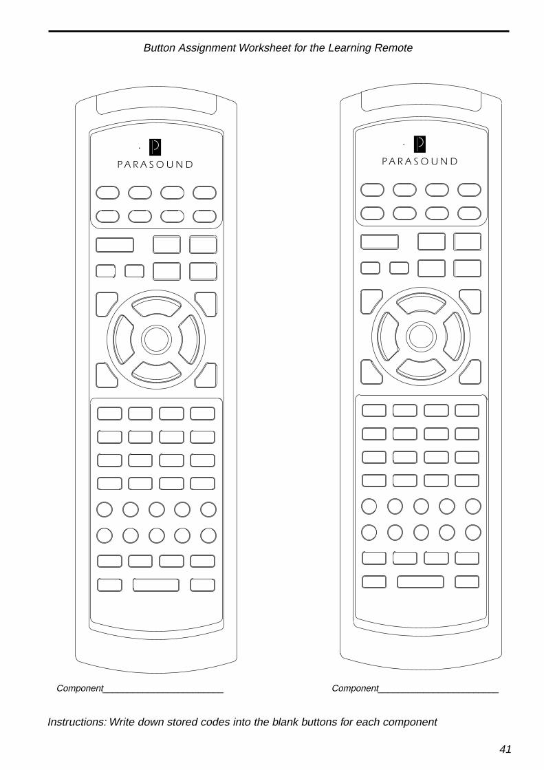
41
Button Assignment Worksheet for the Learning Remote
Component________________________ Component________________________
Instructions: Write down stored codes into the blank buttons for each component

42
Button Assignment Worksheet for the Learning Remote
Component________________________ Component________________________
Instructions: Write down stored codes into the blank buttons for each component

43
AVC-1800 Specifications
Frequency ResponseFront (Large) 10 Hz-20 kHzFront (Samll) 80 Hz-20 kHzRear (Large) 10 Hz-20 kHzRear (Small) 80 Hz-20 kHzCenter (Large ) 10 Hz-22 kHzCenter (Small ) 80 Hz-22 kHzSubwoofer (LPF) 10 Hz-80 HzSubwoofer (300 Hz) 10 Hz-300 Hz
Harmonic DistortionFront < 0.008 %Center < 0.008 %Rear < 0.008 %Subwoofer < 0.008 %
Input ImpedanceAnalog Inputs 10 kΩCoaxial Digital Inputs 75 Ω
IM Distortion(1 kHz 1V Output)All Channels < 0.06 %
Signal/Noise Ratio(Flat/A-Weighted)Front 90 dB / 93 dBCenter 90 dB / 93 dBRear 75 dB / 82 dBSubwoofer 85 dB / 93 dB
Video Section(Output 1 V / 75 Ω Load)Sensitivity 1 V + /- 0.5 dBFrequency Response 0.3 MHz -10 MHz + /- 1 dBOverload 2.5 V P-P
Dimensions17 1/8" wide x 4 1/2" high x 13" deep 5 7/8" high with feet
Weight15 lb
Power Requirements110 V - 120 V 60 Hz AC, 60 W220 V - 240 V 50 Hz AC, 60 W
Features and specifications subject to change without notice

44
AVC-1800 Tuner Specifications
Tuning RangeFM: 87.5 MHz to 108 MHzAM: 520 kHz to 1610 kHz
FM SensitivityMono IHF 11 dBfStereo IHF 37 for 50 dB of quieting
AM SensitivityIHF 10 uV/m
Signal to Noise Ratio>74 dB Stereo 65 dBf IHF Weighted
FM Stereo Separation50 dB @ 1 kHz40 dB @ 10 kHz
FM Selectivity80 dB
AM Selectivity30 dB
FM Frequency Response30 Hz to 15 kHz +/- 1 dB
AM Frequency Response20 Hz to 4.5 kHz +/- 2 dB
Total Harmonic DistortionFM Mono < 0.08 %FM Stereo < 0.2 %
Total Harmonic DistortionAM < 0.5 %
Capture Ratio< 1.5 dB
AM Suppression60 dB

45
Parasound Products, Inc. 950 Battery Street, San Francisco, CA 94111415-397-7100 / FAX 415-397-0144 www.parasound.com
© 2000 Parasound Products, Inc. Rev 0.95