avance dx aqx gcuthe operation mode (i.e. bus configuration, access speed, ready timing ) of the...
TRANSCRIPT

AQX
GCU
Technical ManualBRUKER
Version 002

The information in this manual may be altered without notice.
BRUKER accepts no responsibility for actions taken as a resultof use of this manual. BRUKER accepts no liability for any mis-takes contained in the manual, leading to coincidental damage,whether during installation or operation of the instrument. Un-authorised reproduction of manual contents, without writtenpermission from the publishers, or translation into another lan-guage, either in full or in part, is forbidden.
This manual was written by
T. Eckert and Dr. J. M. Rommel
© May 5, 1996 -Bruker Elektronik GmbH
Rheinstetten, GermanyUpdated for BASH 2.0 by U. Roos - December 1996
P/N: Z31343DWG-Nr: 1052 002

AQX Gradient Control Unit
1
GCU0 incl. EC 01
H2546
BRUKER Analytische Meßtechnik Computer Hardware Manual
1 : AQX Gradient Control Unit
Eckert/Rommel
1(96/02/05)

Goto
AQX Gradient Control Unit
2
GCU0 incl. EC 01
H2546
Contents
BRUKER Analytische Meßtechnik Computer Hardware Manual
1. Technical Description 5
1. 1. General Information 5
1. 2. Features 5
1. 3. Architecture 5
1. 3. 1. Block Diagram 5
1. 4. i960-Processor Environment 8
1. 4. 1. I960 Address Mapping 8
1. 4. 2. i960 global Address Table 8
1. 4. 3. Memory region Configuration 9
1. 4. 4. Memory Region Table ( 256 Mbytes step) 9
1. 5. Detailed Register Set Description 12
1. 5. 1. VME Control Register 12
1. 5. 2. Local I960 Interrupt Register 13
1. 5. 3. VME Interrupt Vector Register 13
1. 5. 4. Communication Box Register 13
1. 5. 5. Gradient Control Register 14
1. 5. 6. Gradient Status Register 15
1. 5. 7. I960 NMI and XINT7 16
1. 5. 8. AQY-Bus INT./Status Register 16
1. 5. 9. AQY-Bus Data/Control Register 16
1. 5. 10. Gradient Data Register X,Y and Z 16
1. 5. 11. Gradient Timing Generator 17
1. 5. 12. Description of special Commands 17
1. 6. Logical References 19
1. 6. 1. I960/VME-Bus Memory map I/O andDevice Code space 19
1. 6. 2. Global i960 Device code table 19
1. 6. 3. Global VME Device codes table 19
1. 6. 4. Detailed i960 and VME Device code tables 20
1. 7. Operational Settings 23
1. 7. 1. Configuration 23
1. 7. 1. 1. VME Interrupt Request (Jumper W5 and W4) 23
1. 7. 1. 2. VME Interrupt Level (Jumper W6) 23
1. 7. 1. 3. Clock Divide (Jumper W3) 23
1. 7. 1. 4. VME Device Code address space selection(Jumper W7) 24
1. 7. 1. 5. Termination of the 40MHZ signal from the TCU(Jumper W1) 24
1. 7. 1. 6. Termination of the AQSTA signal from the TCU(Jumper W2) 24
1. 8. Specifications and Connections 26
1. 8. 1. Construction and Board Size 26
1. 8. 2. Location of Connectors and Controlling Elements 27
2(96/02/05)

Goto
AQX Gradient Control Unit
3
GCU0 incl. EC 01
H2546
1. 8. 3. Connectors and Signal Allocations 28
BRUKER Analytische Meßtechnik Computer Hardware Manual
1. 8. 4. Power Requirements 29
2. Manufacturing Informations 30
2. 1. Manufacturing Data 30
2. 2. Introduction Status 30
2. 2. 1. Configuration 30
2. 2. 2. Assembling 30
2. 2. 3. Modifications of the introduced layout 30
2. 2. 4. Service Informations 30
2. 3. History of Modifications 30
3. Testing 31
3. 1. Testprograms of AQX devices 31
3. 1. 1. Usage 31
3. 1. 1. 1. Where to use the testprograms 31
3. 1. 1. 2. How to start a test program 31
3. 1. 1. 3. Special files used by the test programs 32
3. 1. 1. 4. Main features of the test programs 32
3. 1. 1. 5. Parameter setting 33
3. 1. 1. 6. Overview of tests 34
3. 1. 1. 7. Special TCU test features 36
3. 1. 1. 8. Special GC/GCU test features 37
3. 1. 1. 9. Special MEM test features 37
4. Timing Diagrams 39
4. 1. The AQ Bus 39
4. 2. The Gradient Data I/O Timing 41
3(96/02/05)

Goto
AQX Gradient Control Unit
4
GCU0 incl. EC 01
H2546
Figures
BRUKER Analytische Meßtechnik Computer Hardware Manual
Figure 1: GCU Block Diagram 6
Figure 2: VME Control Register 12
Figure 3: Local Interrupt Register 13
Figure 4: VME Interrupt Vector Register 13
Figure 5: Gradient Status Register 15
Figure 6: Acquisition Data/Control Register 16
Figure 7: Location of Jumpers 25
Figure 8: GCU Front Panel 26
Figure 9: Location of Connectors and Elements 27
Figure 10: Gradient Data I/O Connector 28
Figure 11: AQ Bus signals on the VME J2-connector 29
Figure 12: The AQ Bus Description 39
Figure 13: AQ Bus Timing 40
Figure 14: Gradient Data I/O Timing 41
Tables
Table 1: VME Register Set 20
Table 2: Gradient Data I/O Register Set 20
Table 3: Gradient Timing /Control Register Set 21
Table 4: Real-Time AQ-Bus Device Codes 22
Table 5: No Real-Time AQ-Bus Device Codes 22
Table 6: Table of Assembly Groups 30
4(96/02/05)

Goto
AQX Gradient Control Unit
5
GCU0 incl. EC 01
H2546
e ofhe
e ofith
ient.
BRUKER Analytische Meßtechnik Computer Hardware Manual
1. Technical Description
1. 1. General Information
The Gradient Control Unit (GCU) is an intelligent VME-BUS Slave controller Board with the ability to generatinterrupts on the VME-BUS. A essential part of the GCU is the I80960 microprocessor. The basic functionthe Gradient Control Unit is to calculate on-line the X,Y and Z Gradient values and to control the timing of tD/A conversion. This firmware program is load by the CPU via the VME-Bus. A analog preamphasis Unitconnected to the Gradient D/A converter outputs finally controls the Spectrometer Gradient Field. Becausdigital noise, the D/A converters board is located in a separate unit. A cable is used to interface the GCU wthe D/A converter board (50 way max. length should be 4 meters). The Timing Control Unit (TCU) witchgenerates the Master timing, requests the GCU via the AQ-Bus to calculate a new data set for X,Y and Z GradFurther the TCU provides the GCU with the 40 MHZ reference clock (via coax) for precise Gradient switching .
1. 2. Features
• I80960 Microcontroller with internal 1KB cache and 1KB Data Ram operating at33MHZ without wait states.
• 32 Bit Data/Address VME Bus Slave controller with interrupt capabilities
• fast local 256KB instruction Ram with 0 wait state and pipeline operation
• 8KB additional Data Ram with local Bus for communication between VME Masterand Grad. Controller.
• special VME-Bus register set ( interrupt,status, and configuration)
• 16 Data 8 Add/control Bit Interface to the Grad. D/A converter unit
• 32 Bit Timer with 25ns resolution to control the Gradient timing when producinga Ramp or other special Gradient waveforms.
1. 3. Architecture
1. 3. 1. Block Diagram
The Gradient Controller can be distinguished in six groups.
• 1. VME - Bus Interface
• 2. I960 Processor Kernel
• 3. Arbiter between I960 and VME-Bus
• 4. Reset Control
• 5. Grad. Timer and AQ-Bus Interface
• 6. Grad. D/A converter Interface
5(96/02/05)

Goto
AQX Gradient Control Unit
6
GCU0 incl. EC 01
H2546
Figure 1: GCU Block Diagram
BRUKER Analytische Meßtechnik Computer Hardware Manual
6(96/02/05)

Goto
AQX Gradient Control Unit
7
GCU0 incl. EC 01
H2546
VME-Bus Interface
To and
ersable anVME-.
dotion,apter
e theder.
e
asocate
ortive,
am
te
Eh
BRUKER Analytische Meßtechnik Computer Hardware Manual
The Interface to the VME-Bus is designed as a 32 bit address/data Bus Slave with Interrupt capabilities. simplify the Interface only 32/16 bit data access are possible (no nibble or page access). The instructiondata ram and nearly all registers are read-/ writeable from the VME-Bus which is important for testing. Allfunctions, witch normally are controlled by the I960, can also be activated from a VME-Bus Master. The registin the D/A converter board,witch are connected to the Gradient control unit via a 50 way cable are also testfrom VME-Bus. For communication and data exchange between a VME-Bus Master and the I960 there is8KB data ram and the VME registers set, located on an separate internal Bus.. The advantage is ,that the Master can access the local VME register or data RAM without interruption of the I960 program execution
I960 Processor Kernel
An important part of the Gradient Control Unit is the Intel I960 Microprocessor operating at 33MHZ with builaround 256KB fast (20ns) SRAM and 64KB EPROM. The EPROM (8 bit data width) contains the initial borecord for the I960 after power-up and the GNU debugger software. The operation mode (i.e. Bus configurataccess speed, ready timing ) of the I960 bus controller is programmable. For a detailed description see ch”Memory region configuration”. In this application the I960 operates with the external 32 bit instruction RAMin pipeline mode ,with 0 wait state on read and 2 wait state on write cycles. Fast PALs are used to generatram address for pipeline operation. The I960 Address Mapping is decoded by the GCU internal device decoThe I960 has an on chip interrupt controller with 8 dedicated interrupt pins and a separate NMI input. Theinterrupt are low level detected. The NMI is used to detect any real-time actions on the AQ-Bus such as thoccurrence of an NG pulse. The INT7 is used to signal any timing error condition on the AQ-Bus interfacemeanwhile INT0-6 can be used by the VME Master to interrupt the I960.
Arbiter between I960 and VME-Bus
Any access from the VME Bus or I960 to the resources on the GCU are supervised by the Arbiter. WhereI960 accesses has higher priority as VME-Bus accesses. There are two possible ways for the arbiter to allaccesses from the VME Bus to the GCU.
1. The ready signal of the I960 is controlled by the arbiter . An access from the VME- Bus to the data RamVME register set is delayed until the ready signal is inactive. In the other case the I960 waits for ready be acwhen it access this region ,before it continues its current cycle.
2. The Hold Request signal on the I960 is set by the arbiter if a VME Master wants access the instruction Ror Gradient Register Set (Timer,control reg,DAC reg.). The I960 signals the arbiter with theHOLDACK line that it has released the intern Bus and the VME-Bus access is granted.
Reset Control
The reset logic is used to initialize the Gradient Controller and I960 processor. Three conditions will activathe reset logic:
• 1. Power up reset
• 2. VME-Bus System reset
• 3. Software reset
After RESET the control logic on the board is ready to work whereas the I960 will be stay in RESET STATuntil a GO command is given by the Host CPU. In this state the CPU can load the I960 instruction ram witexecutable program code or the proper operation of the GCU can be tested via VME -Bus.
7(96/02/05)

Goto
AQX Gradient Control Unit
8
GCU0 incl. EC 01
H2546
Gradient Timer and AQ-Bus Interface
GCUs and
er. set
sistthe isals
ntrol D/AputsGCUsis
ved orsed6
BRUKER Analytische Meßtechnik Computer Hardware Manual
The Grad. Timer is a 32 bit programmable counter used to generate a constant periodical time base for the to produce special Gradient shapes such as a Ramp or other waveforms. The Timer has a resolution of 25na min. cycle time of 125ns. The Timing Control Unit (TCU) provides the Timer with the 40MHz clock. Ifenabled by the GCU, an device code (i.e. NG) given by the TCU over the real-time AQ-Bus starts the TimThe occurence of the NG-pulse loads the D/A converter from the X,Y and Z register board with a new dataand the I960 is interrupted with the NG-FLAG set. Three sources can generate an NG-pulse :
• 1. The TCU over the real-time AQ-Bus
• 2. The Grad. Timer if enabled
• 3. The VME-Master (only for testing)
The AQ-Bus Interface consist of two parts, a real-time and a non real-time Bus. The real-time interface conof an 8 bit address, 4 bit data Bus and 2 control signals. All GCU actions witch should be synchronic with TCU timing are controlled via the real-time AQ-Bus (i.e. NG-pulse,dummy scan). The no real-time AQ-Busused for communication between the TCU and the GCU. It consist of an 8 bit add/data Bus, 4 control signand an interrupt signal. The interrupt is used by the GCU to signal the TCU any error condition.
Grad. D/A converter Interface
The Interface between the GCU and the D/A converter unit consist of a 16 bit data Bus, 4 address and 4 cosignals . The data for the X,Y and Z Gradient are transferred to the corresponding register, located on theconverter board, via a 50 way cable. An NG-Pulse from the GCU enables the data set to the D/A converter inwhereby the respective analog signal is set. The registers on the D/A converter board are readable by the witch is important for testing. The analog outputs (X,Y,Z) of the D/A converter are connected to the preamphaunit located in the same box.
1. 4. i960-Processor Environment
1. 4. 1. I960 Address Mapping
The i960 Processor has an linear address space from 0 to 2^(31) -1. Some of this address space is reserassigned to special functions. A memory address is a 32 bit value within 0 and FFFFFFFF Hex . It can be uto reference single byte , 2 bytes , 4 bytes , double word (8 bytes), triple word (12 bytes) or quad words (1bytes) in memory, depending on the instruction being used. The i960 address space is shown below:
1. 4. 2. i960 global Address Table0000 0000 - 0000 0003 NMI VECTOR
0000 0004 - 0000 003F INTERNAL DATA RAM (OPT. INTERRUPT VECTORS)
0000 0040 - 0000 00BF INTERNAL DATA RAM (OPTIONAL DMA REGISTER)
0000 00C0 - 0000 00FFINTERNAL DATA RAM (USER WRITE PROTECTED)
0000 0100 - 0000 03FFINTERNAL DATA RAM (USER WRITE PROTECTED
0000 0400 - FEFF FFFF EXTERNAL MEMORY CODE OR DATA
FF00 0000 - FFFF FEFFRESERVED
FFFF FF00 - FFFF FF2CINITIALIZATION BOOT RECORD
FFFF FF2D - FFFF FFFFRESERVED MEMORY
8(96/02/05)

Goto
AQX Gradient Control Unit
9
GCU0 incl. EC 01
H2546
1. 4. 3. Memory region Configuration
. TheressUisns.
edonter
eter
low:
ntrol, theare any
BRUKER Analytische Meßtechnik Computer Hardware Manual
The address space of the i960 can be mapped as read-write, read-only memory and memory mapped I/Owhole memory space is divided into 16 regions each 256 MBytes in range. The upper four bits of the add( A31 - A28 ) indicate which of the 16 regions is currently selected. The memory configuration for the GCis as follows. The regions 0 to 7 are reserved for the inst./data SRAM. The 1KB internal RAM of the i960 mapped into region 0. The internal RAM of the I960 can only be accessed by loads, stores, or DMA instructioThe regions 8,9,A are reserved for user definable memory space (i.e. VME DMA I/O ). Region B is usfor VME I/O devices codes i.e VME interrupt vector register, VME address modifier register, CommunicatiBox register, Control register , and local interrupt register. Region C is used for the Gradient Data RegisSET (i.e. X,Y and Z Data reg.) . Region D is used for the external 8KB Data Ram (Gradient Data param) . Region E is used for the Gradient Control Registers (i.e Timer ,AQ-Bus Flags,NG-Flags,NMI) whereasRegion F is used for the EPROM boot sequence and for monitor code. The memory table entry is shown be
1. 4. 4. Memory Region Table ( 256 Mbytes step)0000 0000 - 0FFF FFFFREGION 0SRAM_CONF (internal 1KB data RAM)1000 0000 - 1FFF FFFFREGION 1EXTERNAL 256 KB I/D SRAM CONF.2000 0000 - 2FFF FFFFREGION 2 SRAM_CONF3000 0000 - 3FFF FFFFREGION 3SRAM_CONF4000 0000 - 4FFF FFFFREGION 4 SRAM_CONF5000 0000 - 5FFF FFFFREGION 5 SRAM_CONF6000 0000 - 6FFF FFFFREGION 6SRAM_CONF7000 0000 - 7FFF FFFFREGION 7SRAM_CONF8000 0000 - 8FFF FFFFREGION 8RESERVED FOR VME-BUS DMA9000 0000 - 9FFF FFFFREGION 9 ” ”A000 0000 - AFFF FFFFREGION A ” ”B000 0000 - BFFF FFFFREGION BVME_DEVICE_CODEC000 0000 - CFFF FFFFREGION CGRAD_DATA_REGISTERD000 0000 - DFFF FFFFREGION DEXTERNAL 8KB DATA RAME000 0000 - EFFF FFFFREGION EGRAD. CONTROL_REG.
F000 0000 - FFFF FFFFREGION FEPROM_CONF
Each region has independent software programmable parameters that define the data-bus width, ready conumber of wait states, pipeline read mode, byte ordering and burst mode. These parameter are stored inmemory-region configuration table. The purpose of configurable memory regions is to provide system hardwinterface support. Because of slow external memory devices the i960 must generate wait states for region. Five parameters define the wait-state-generator operation:
NRAD - Number of wait cycles for Read Address-to-DataNRDD - Number of wait cycles for Read Data-to-DataNWAD - Number of wait cycles for Write Address-to-DataNWDD - Number of wait cycles for Write Data-to-DataNXDA - Number of wait cycles for X (read or write)Data-to-AddressShown below is the Memory Region configuration for the GCU.
Region 0-7 Inst. SRAM configuration table ( region 0-7) with 20 ns access time
Data-Bus Width 32 Bit NRAD 0 wait states NRDD 0 wait states NWAD 2 wait states NWDD 2 wait states
9(96/02/05)

Goto
AQX Gradient Control Unit
10
GCU0 incl. EC 01
H2546
NXDA 0 wait states
BRUKER Analytische Meßtechnik Computer Hardware Manual
Pipelining YES External Ready NO BURST YES
Region B configuration table VME_DEVICE_ Code
Data-Bus Width 32 Bit NRAD 3 wait states NRDD 1 wait states NWAD 3 wait states NWDD 1 wait states NXDA 0 wait states Pipelining NO External Ready YES Burst NO
Region C configuration table Grad.- Data REG. Device Code
Data-Bus Width 16 Bit NRAD 6 (3) wait states NRDD 3 wait states NWAD 4 ( 3) wait states NWDD 3 wait states NXDA 0 wait states Pipelining NO External Ready NO Burst NO
Region D configuration table Data/Parm SRAM with 25 ns access time
Data-Bus Width 32 Bit NRAD 3 wait states NRDD 1 wait states NWAD 3 wait states NWDD 1 wait states NXDA 0 wait states Pipelining NO External Ready YES Burst YES
10(96/02/05)

Goto
AQX Gradient Control Unit
11
GCU0 incl. EC 01
H2546
Region E configuration table Grad.- Control REG. Device Code
BRUKER Analytische Meßtechnik Computer Hardware Manual
Data-Bus Width 16 Bit NRAD 2 wait states NRDD 2 wait states NWAD 2 wait states NWDD 2 wait states NXDA 0 wait states Pipelining NO External Ready NO Burst NO
Region F EPROM_DEVICE Code configuration table
Data-Bus Width 8 Bit NRAD 6 wait states NRDD 3 wait states NWAD 5 wait states NWDD 3 wait states NXDA 1 wait states Pipelining NO External Ready NO Burst NO
11(96/02/05)

Goto
AQX Gradient Control Unit
12
GCU0 incl. EC 01
H2546
1. 5. Detailed Register Set Description
forister
nest
orhe0tion
e
the
BRUKER Analytische Meßtechnik Computer Hardware Manual
The Register set can be general distinguished in two groups:
• 1. VME-Bus oriented Register
• 2. Gradients control/data oriented Register
Nearly all Register can be read and written from a VME_Bus Master and from the I960 processor (useful test and debugging). From the VME-Bus all register are referenced as longword and from the I960 the regare addressed as long, short or byte. A detailed bit description of the different registers is given below.
1. 5. 1. VME Contr ol Register
The VME control register is an 8 bit read/writeable register used to control the global operation of the I960processor from the host CPU.
Figure 2: VME Control Register
ESTEST : If set (1) the internal selftest on the I960 is enabled . The I960 will execute the selftest operatioafter reset and test its internal register and bus structure and the external Bus for any contention. If the Tpasses through without an error the front LED is switched off, otherwise the LED will be on.
EVPR : Setting this Bit to 1 allows a VME-Bus Master to access the I960 local instruction Ram without prisetting the I960 in the Hold or Reset State. Therefor the I960 will only be in Hold State for the duration of tVME access cycle.If set to 0 the local instruction Ram is not accessible by a VME-Bus Master until the I96is in reset or continue Hold State. This bit should only be set to 1 for test and debugging and not in an applicaprogram because the I960 execution time will dramatically increased ,when an VME-Bus cycle take placebetween the I960 instruction cycles .
HLDC : If set to 1 the I960 will go into the continue Hold state. For example to load a new program or initializthe I960 . The I960 will leave the Hold state if this bit is set to 0.
EVIRQ : If set 1 the I960 can generate an interrupt request on the VME-Bus .When set to 0 the interrupt to VME-Bus is disabled.
XXXX : The bits 4 - 7 are not used.
Bit 7 Bit 5 Bit 4 Bit 3 Bit 2 Bit 1 Bit 0Bit 6
ESTESTEVPRHLDCEVIRQXXXXXXXXXXXXXXXXXXXX
i960 Selftest1=enabled0=disabled
Enable VME Bus to Instr. RAM1=enabled0=disabled
Processor Hold1=continue Hold0=Run
VME Interrupt Request1=enabled0=disabled
12(96/02/05)

Goto
AQX Gradient Control Unit
13
GCU0 incl. EC 01
H2546
1. 5. 2. Local I960 Interrupt Register
ctedre
bit
le.
tion
BRUKER Analytische Meßtechnik Computer Hardware Manual
This register is used to set a dedicated interrupt on the I960 processor. The Bits 0 - 6 are directly conneto the I960 interrupt pins XINT0 - XINT6. They are activ if set to LOW. Bit 7 is not used for interrupt, therefoit can be used for hardware debugging. Setting this register to FF all interrupts will be inactive. Normally thHost will set an interrupt bit to tell the I960 that a break condition has occurred. The I960 should clear thisbefore it returns from the interrupt service routine.
Figure 3: Local Interrupt Register
1. 5. 3. VME Interrupt V ector Register
An 8 Bit width register used to store the appropriate interrupt vector for an VME-interrupt acknowledge cycIt should be written by the Host CPU before any interrupt action of the Gradient controller is started.
Figure 4: VME Interrupt Vector Register
1. 5. 4. Comm unication Bo x Register
This is an 32 bit register which is physically located in the dual port data Ram and is used as a communicapath between the VME-Bus Host and the I960 processor.
Bit 7 Bit 5 Bit 4 Bit 3 Bit 2 Bit 1 Bit 0Bit 6
XINT0XINT1XINT2XINT3XINT4XINT5XINT6XXXXX
Bit 7 Bit 5 Bit 4 Bit 3 Bit 2 Bit 1 Bit 0Bit 6
VD0VD1VD2VD3VD4VD5VD6VD7
13(96/02/05)

Goto
AQX Gradient Control Unit
14
GCU0 incl. EC 01
H2546
1. 5. 5. Gradient Contr ol Register
on (seelow.
e isset,nalther
dienter to.-,Znsehe
rter
Ifetheauset or
ein
BRUKER Analytische Meßtechnik Computer Hardware Manual
There are several single bit registers (i.e. RAMP,DP,ENGI,TM,AQI) used to control the Grad. Timer operatias well as the detection and generation of an NG-Pulse. The control bits can be separately read and writtenFigure 4.3.3). The default value of all these register after power up is 0. A detailed bit subscription is given be
Ramp control Register (RAMP)
This one bit register is used to alert the Grad. Timer. If set to 1 the Grad. Timer is started when an NG-pulsdetected. The Timer will then generate periodical NG.-Pulses and request the I960, with NMI or NG._Flag to issue new values for x,y, and z Gradient. In this way a ramp or any other waveform of the Gradient sigcan be produced with constant time intervals. The Timer should be stopped (Ramp Bit set to 0) before a furNG.- Pulse is generated by the TCU. Otherwise an error interrupt will occur.
Digital Preamphasis control Register (DP)
If the GCU should calculate the preamphasis, needed to adjust the gradient current to the respective gracoil, instead using the analog preamphasis control, the DP register should be set to 1. This alert the Timstart on the next NG-Pulse . The Timer will then generate a periodical clock (GCLK) in addition to the NGPulse from the TCU. On every falling edge of the GCLK signal the actual preamphasis data set for the X,Yand the B0 correction, stored in the D/A register, is transferred to the D/A converters. The I960 should thecalculate and load the D/A register with a new data set before the next edge of GCLK occurs. An NG.-Pul,generated by the TCU, signals the I960 by an NMI, that it has to issue a new data of nominal values for tX,Y,Z Gradient. If the DP register is set to low digital preamphasis is disabled and the timer is stopped.
Enable Grad. Interrupt (ENGI)
The Interrupt (I960 NMI) generated by an NG.-Pulse can be enabled if the ENGI register is set to high odisabled if set to low. In some time critical applications it can be better to poll the NG.-Flag instead to enin the NMI service routine. For this reason it is possible to disable the NMI.
Test Mode Register (TM)
The TM register is provided to test some hardware register and control logic on the GCU board, withoutconnecting the TCU or AQ-Bus. This can be useful to check the interface to the TCU is working correct. the TM register is set to 1 the Grad. Timer is provided with the onboard 33MHZ system clock instead of th40MHZ input from the TCU. Further the real time AQ-Bus flags (RAQD0-3) can than be set and cleared by I960 and the NG.-Pulse, normally generated by the TCU, can be simulated by the I960 via device codes. Becthe TM register is only interesting for tests it should not be used on normal operation. On default, after resepower up, the Test Mode is off (TM = Low).
Acquisition Interrupt Register (A QI)
An interrupt (AQI) to the TCU over the AQ-Bus is provided to inform the TCU about an error occurred on thGCU. The TCU should read the AQ- Status register on the GCU when detecting AQI active (LOW) to obtathe error condition. The AQI is cleared (HIGH) when the TCU reads the AQ-Status register.
14(96/02/05)
Goto
AQX Gradient Control Unit
15
GCU0 incl. EC 01
H2546
1. 5. 6. Gradient Status Register
enere
d
alues1) ised by
etallyhe
toen
ether
BRUKER Analytische Meßtechnik Computer Hardware Manual
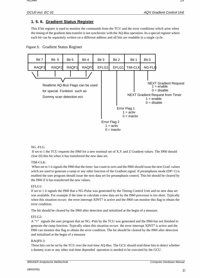
This 8 bit register is used to monitor the commands from the TCU and the error conditions which arise whthe timing of the gradient data transfer is not synchronic with the AQ-Bus operation. Its a special register wheach bit can be separately written on a different address and all bits are readable in a single cycle.
Figure 5: Gradient Status Register
NG.-FLG: If set to 1 the TCU requests the I960 for a new nominal set of X,Y and Z Gradient values. The I960 shoulclear (0) this bit when it has transferred the new data set.
TIM-CLK: When set to 1 it signals the I960 that the timer has count to zero and the I960 should issue the next Grad. vwitch are used to generate a ramp or any other function of the Gradient signal. If preamphasis mode (DP=enabled the user program should issue the next data set for preamphasis control. This bit should be clearthe I960 if it has transferred the new values.
EFLG1:If set to 1 it signals the I960 that a NG-Pulse was generated by the Timing Control Unit and no new data swas available. For example if the time to calculate a new data set by the I960 processor is too short. Typicwhen this situation occurs the error interrupt XINT7 is active and the I960 can monitor this flag to obtain terror condition.
The bit should be cleared by the I960 after detection and initialized at the begin of a measure.
EFLG2:A ”1” signals the user program that an NG.-Puls by the TCU was generated and the I960 has not finishedgenerate the ramp function. Typically when this situation occurs the error interrupt XINT7 is active and thI960 can monitor this flag to obtain the error condition. The bit should be cleared by the I960 after detectioand initialized at the begin of a measure
RAQF0-3:These bits can be set by the TCU over the real-time AQ-Bus. The GCU should read these bits to detect wha dummy scan or any other real-time depended operation is needed to be executed by the GCU.
Bit 7 Bit 5 Bit 4 Bit 3 Bit 2 Bit 1 Bit 0Bit 6
NG-FLGTIM-CLKEFLG1EFLG2RAQF0RAQF1RAQF2RAQF3
NEXT Gradient Request1 = enable0 = disable
NEXT Gradient Request from Timer1 = enable0 = disable
Error Flag 11 = activ0 = inactiv
Error Flag 21 = activ0 = inactiv
Realtime AQ-Bus Flags can be used
for special Funktion such as
Dummy scan detection ect.
15(96/02/05)

Goto
AQX Gradient Control Unit
16
GCU0 incl. EC 01
H2546
1. 5. 7. I960 NMI and XINT7
by
MI/
ldn.
al-ews:,U
asU
e as
ted the
usedster.
reloadhed.
t the
BRUKER Analytische Meßtechnik Computer Hardware Manual
The NMI will be set by an NG.-Puls from the TCU or from the timer clock and should be cleared (set to 1) the I960 before it returns from the interrupt service routine. The Interrupt ’XINT7’ will be activated (0) if oneof the above error conditions, where FLG1 or FLG2 are set, occurs. Specially for test or debugging the NXINT7 can be set and cleared by the Host CPU or the I960 itself .
1. 5. 8. AQY-Bus INT./Status Register
This 8 bit write only register is used to store the interrupt status information for the TCU. The TCU shouread this register if it detects that the ”AQI7” is active to obtain detailed information about the interrupt conditioThe ”AQI7” will be cleared after the TCU has read the Int/Status register.
1. 5. 9. AQY-Bus Data/Contr ol Register
Via the AQY-Data register the TCU can send the GCU an 8 bit data word (AQY7-0) for general use (no retime) such as special triggering methods or conditional gradient program execution. A software handshakmechanisms is used to insure that the GCU read valid data written by the TCU. The handshake is as folloFirst the TCU write into the AQY- data register and then it sets the control flag ”ACF0” equal LOW. The GCUseeing the ”ACF0” set, reads then the AQY-data register and clears (set to HIGH) the ”ACF0”. Further the TCcan send a 4 bit control word (AQF3-0) to the GCU over the AQY-Bus. The same handshake mechanismsabove , except the ”ACF1” handshake flag, is used to signal the GCU that the ”AQF3-0” are valid. The GCreads the AQY-Data and control register in one cycle as a 16 bit word. The corresponding bit locations arfollows:
Figure 6: Acquisition Data/Control Register
Note: xxx not used
1. 5. 10. Gradient Data Register X,Y and Z
The X,Y and Z Gradient Data Register are 16 bit wide and are located in the D/A converter unit witch is connecto the Gradient Controller. These read- /writeable registers are used to store the actual Gradient value fornext D/A conversion.
The B0,B1 and B2 correction data register are each 16 bit register located in the D/A converter unit and are to store the current values for the preamphasis correction, related to the data in the X,Y and Z Gradient regi
The PX,PY,PZ and PB0,PB1,PB2 are the equivalent register to those above. These registers are needed to pa data set (X,Y,Z) in the case of the occurrence of a NG-Puls while the current preamphasis is not being finis
A special read back register (see figure 4.3.2) is provided to test the Gradient data output operation withouconnection of the external D/A converter unit (useful for test and debugging).
D15 D14 D13 D12 D11 D10 D9 D8 D7 D6 D5 D4 D3 D2 D1 D0
ACF
1
ACF
0
XXX XXX AQF
3
AQF
2
AQF
1
AQF
0
AQY
7
AQY
6
AQY
5
AQY
4
AQY
3
AQY
2
AQY
1
AQY
0
16(96/02/05)

Goto
AQX Gradient Control Unit
17
GCU0 incl. EC 01
H2546
1. 5. 11. Gradient Timing Generator
r5nsiteeded
nter
theusset
nitial
ME
ly
ice
the
vice
Uwo
BRUKER Analytische Meßtechnik Computer Hardware Manual
This is an 32 bit counter witch generates the correct timing for the D/A conversion if digital preamphasis oramp mode is enabled. The counter is clocked with 40MHz provided by the TCU and it has a resolution of 2with a minimal clock period of 125ns. The counter is loaded from the Gradient data I/O Bus , witch is 16 bwide, therefore two access cycles are necessary to write or read the 32 bit counter. To calculate the value, nby the counter to generate the appropriate clock rate use the following equation (V=T/25ns-1).V = decimal value to load the counter.T = Time in ns.For example, if you want a clock rate of 1us than (1000ns/25ns -1 = 39 or 0x27 hex) you must load the couwith hex 27.
1. 5. 12. Description of special Commands
Soft Reset
The Host CPU can reset the Gradient Control Unit with this device code and the I960 processor will go in reset state until it will be started with the Go command. While the I960 processor is in reset state a VME-BMaster can access the internal instruction RAM, for example to load a program or to test this RAM. In the restate the front LEDs ’STEST’ and ’HOLD’ are switched on.
Go Command
This Device Code is used to release the I960 processor from the reset state. The I960 will than execute the iprogram located in the PROM and than it will branch to the instruction Ram.
VME Interrupt Request
The I960 processor or the Host CPU can write to this Device code to generate an Interrupt request on the V-Bus. Prior to this action the ’EVIRQ’ bit in the VME - Control register must be set to enable this function.
Generate NG.-Test Puls
This Device Codes is provided for test and debugging. It is used to simulate the NG Trigger Pulse normalgenerated by the TCU. The ’TM’ bit must be set (HIGH) prior to generate the NG.-Pulse.
Clear DAC Register
To initialize the Gradient D/A converter at the begin of the measurement or after an error condition , this DevCode is provided to set the DAC output at 0 voltage.
Clear AQY-Bus control Flags
Two AQY-Bus control flags (ACF0,ACF1) are used for the handshake mechanisms between the TCU andGCU. The ’ACF0’ flag signals valid data in the AQY-Bus Data register and the ’ACF1’ signals valid data inthe AQY-Bus control word. The flags are set by the TCU and cleared if the GCU reads the corresponding decodes.
AQ-Bus short description
In the new acquisition system a special Bus (AQ-Bus) is defined as a communication path between the TC,FCUs,RCU and GCU. The AQ-Bus is located on the P2 connector of the VME-Bus and is distinguished in tgroups:
• 1. Real-time AQ-Bus (unidirectional)
• 2. No real-time AQY-Bus (bidirectional)
17(96/02/05)

Goto
AQX Gradient Control Unit
18
GCU0 incl. EC 01
H2546
The TCU witch generate the exact timing for the acquisition is master on the real-time AQ-Bus and controlsw.
ortion
BRUKER Analytische Meßtechnik Computer Hardware Manual
the time relevant actions of all other AQ.- Units. For detailed timing and pin assignment see the sheet beloThe no real-time AQY-Bus is used as a bidirectional communication path between the AQ.-Units. The TCUsend the GCU no real-time depended data and control information needed for special triggering methodsconditional program execution. In the other direction the GCU use this bus to send the TCU a status informa(i.e. interrupt status).
18(96/02/05)

Goto
AQX Gradient Control Unit
19
GCU0 incl. EC 01
H2546
1. 6. Logical References
60 i960
cetes aredress byehe
n thevery used
BRUKER Analytische Meßtechnik Computer Hardware Manual
1. 6. 1. I960/VME-Bus Memory map I/O and Device Code space
The GCU Board has 256 kByte Static RAM for Instruction and Data code. This SRAM is mapped in the i9address space from 1000 0000 to 1003 FFFF. The I/D RAM is byte addressable and its guaranteed to theprocessor that an access within a 16 byte boundaries is indivisible for other masters until the operation iscomplete. The VME I/O devices space in region B is long word aligned. The Gradient I/O device spain region C and E is word aligned for I960 access and long word aligned for VME access. The last 256 MByregion of the address space ( F000 0000-FFFF FFFF ) is reserved for the EPROM ,whereby only 64KByteused. This EPROM is only 8Bit width and is byte addressed. The base address of the EPROM starts at adF000 0000 and ends at F000FFFF. The initial boot record block is located in EPROM an can be accessedthe i960 at address FFFFFF00-FFFFFF2C. Further the EPROM includes a monitor and debug program. Taddress space is not fully decoded, therefor the EPROM will be seen by the i960 every 64KB steps betweeaddress space of F000 0000 and FFFF FFFF. AT the same reason the I/D RAM will be found by the i960 e265KByte step between the address space of 0000 0000 and 8000 000. A table of the i960 devices codesin the Gradient Control Unit are shown below.
1. 6. 2. Global i960 Device code table1000 0000 - 1003 FFFF EXTERNAL I/D RAM 256 kByte
1003 FFFF - 7FFF FFFF unused EXTERNAL RAM SPACE
8000 0000 - AFFF FFFF reserved for VME DMA I/O space
B000 0000 - BFFF FFFF VME REGISTER SET
C000 0000 - CFFF FFFF GRAD. DATA I/O
D000 0000 - DFFF FFFF EXTERNAL DATA RAM 8KB
E000 0000 - EFFF FFFF GRAD. CONT. REG.
F000 0000 - FFFF FFFF EPROM 64 kByte
1. 6. 3. Global VME Device codes table1840 0000 - 1843 FFFF i960 Instr./Data RAM (256KB)
1847 0000 - 1847 1FFF i960 Data only RAM 8KB (Grad. Parameter)
1847 8000 - 1847 800C VME Register Set
1847 A000 - 1847 A1A4 Grad. Data I/O ,Timing Generator and Cont Reg.
19(96/02/05)

Goto
AQX Gradient Control Unit
20
GCU0 incl. EC 01
H2546
1. 6. 4. Detailed i960 and VME Device code tables
BRUKER Analytische Meßtechnik Computer Hardware Manual
Table 1: VME Register Set
Table 2: Gradient Data I/O Register Set
Address
B000 0000
LengthReadWrite Function
B000 0008 BYTE
BYTE
B000 0010 BYTE R/W
R/W
R/W
i960Address
VME
1847 8000
1847 8004
1847 8008
VME interrupt vector register
VME control register
local i960 Interrupt register
E000 00E0 1847 A0E0 LWORD W generates an interrupt toVME Bus
D0001FFC 1847 1FFC LWORD R/W VME Communication Box
XXXXXXXX
XXXXXXXX
1847 8010
1847 8014
LWORD
LWORD
W
W
Soft Reset command
GO Command
Address
C000 0000
LengthReadWrite Function
C000 0002 Word
Word
Word
C000 0004
C000 0006
Word
Word
R/W
C000 0008
C000 000A
C000 000C
C000 000E
R/W
R/W
C000 0010
C000 0012
C000 0014
C000 0016
C000 0020
R/W
R/W
R/W
R/W
R/W
R/W
R/W
R/W
R
Word
Word
Word
Word
Word
Word
Word
Word
R/W
i960Address
VME
1847 A000
1847 A100
1847 A004
1847 A104
1847 A008
1847 A108
1847 A00C
1847 A10C
1847 A010
1847 A110
1847 A014
1847 A114
1847 A020
X Gradient Data register
Y Gradient Data register
Z Gradient Data register
B0 Correction Data register
B1 Correction Data register
B2 Correction Data register
PX X Gradient preload register
PY Y Gradient preload register
PZ Z Gradient preload register
PB0 B0 Correction preloadregister
PB1 B1 Correction preloadregister
PB2 B2 Correction preload register
read back last Gradient Data
only as Test Function
C000 001E 1847 A11C Word W Clear DAC register (0)
20(96/02/05)

Goto
AQX Gradient Control Unit
21
GCU0 incl. EC 01
H2546
Table 3: Gradient Timing /Control Register Set
BRUKER Analytische Meßtechnik Computer Hardware Manual
Address
E000 0040
LengthReadWrite Function
E000 0042 Word
Word
E000 0062 Word/Bit
E000 0064
E000 0066
E000 0068
E000 006A
R/W
R/W
E000 006C
E000 006E
E000 0070
W
R/W
R/W
R/W
R/W
R/W
R/W
W
i960Address
VME
1847 A040
1847 A140
1847 A160
1847 A064
1847 A164
1847 A068
1847 A168
1847 A06C
1847 A16C
1847 A070
Timing Generator LOW Word
Timing Generator HIGH Word
NMI to I960 (signals NG or TIM-CLK)
INT7 to I960 (signals error condition)
NG. FLAG
Timer Clock FLAG
Error FLAG1
Error FLAG2
REAL TIME AQ-BUS FLAG 0
REAL TIME AQ-BUS FLAG 1
E000 0072 1847 A170 REAL TIME AQ-BUS FLAG 2
E000 0074
E000 0080
E000 0082
1847 A074
1847 A080
1847 A180
R/W
R/W
R/W
R/W
Word/Bit
Word/Bit
Word/Bit
Word/Bit
Word/Bit
Word/Bit
Word/Bit
Word/Bit
Word/Bit
Word/Bit
Word/Bit
E000 0084
E000 0086
E000 0088
E000 008A
1847 A184
1847 A088
1847 A188
Word/Bit
Word/Bit
Word/Bit
Word/Bit
R/W
R/W
W
R/W
1847 A084
E000 00A0
E000 00A0
E000 00A2
E000 00A4
1847 A0A0
1847 A0A0
1847 A1A0
1847 A0A4
Word
Word
Word
Word/Bit
W
R
R
R
E000 00A6 1847 A1A4 Word/Bit R
E000 008C 1847 A08C Word/Bit R/W
REAL TIME AQ-BUS FLAG 3
Digital Preamph. Control
Ramp Control Bit
Enable Grad. Int.(NMI) ENDI
Test Mode (TM)
NG. Test Pulse
generate INT on AQ-Bus
Both Ramp and ENGI set or cleared
AQY-Bus INT Status Register
AQY-Bus Data & Cont. Flag
Test AQY-Bus Interrupt set
Clear AQY-Bus Cont. Flag0
Clear AQY-Bus Cont. Flag1
21(96/02/05)

Goto
AQX Gradient Control Unit
22
GCU0 incl. EC 01
H2546
Table 4: Real-Time AQ-Bus Device Codes
BRUKER Analytische Meßtechnik Computer Hardware Manual
Table 5: No Real-Time AQ-Bus Device Codes
AQ-Bus ADD Write AQ-Bus Data Bits Function
0x90 W D0=1 select NG-Pulse
0x94 W D0 - D3 real-time AQ data dummyscan ect.
Y-Bus ADD VME ADDTCU
Read/Write
Data Bits Function
0x90 19221640 W D0 - D3 AQY control Reg.
0x94 19221650 W D0 - D7 AQY data Reg.
0x98 19221660 R D0 - D7 AQY data Reg.
0x98 19221660 W D0=1 AQY cont. Flag0
0x9C 19221670 W D0=1 AQY cont. Flag1
0x9C 19221670 R D0 - D1 AQY cont. Flag 0-1
0x94 19221650 R D0 AQY INT. Flag
22(96/02/05)

Goto
AQX Gradient Control Unit
23
GCU0 incl. EC 01
H2546
1. 7. Operational Settings
e
BRUKER Analytische Meßtechnik Computer Hardware Manual
1. 7. 1. Configuration
1. 7. 1. 1. VME Interrupt Request (Jumper W5 and W4)
The VME Interrupt request lines are selected by these jumpers. Only one of them should be set.
1. 7. 1. 2. VME Interrupt Level (Jumper W6)
This jumper is used to set the appropriate VME Interrupt Level . The configuration should correspond to thsetting of the Interrupt request jumper.
1.7.1.3. Clock Divide (Jumper W3)
The system clock driven by the I960 can be divide by two with this jumper.
W5 W4
1-2 ------
1
IRQ
W4W51 13 5 7 3 5
2 4 6 8 2 4 6
3-45-6 ---
---7-8--- 1-2
3-4------ 5-6
234567
3-45-6
INININ 1
INT. LEVEL
W61 3 5
2 6
INOUTIN
IN OUTINOUT
OUT INOUTOUT
234567
4 1-2
INOUTIN
OUTIN
OUTIN
OUTOUT OUT
X unused no valid conf.
W31 2 1-2
INOUT 33MHZ
16MHZ
System Clock
23(96/02/05)

Goto
AQX Gradient Control Unit
24
GCU0 incl. EC 01
H2546
1.7.1.4. VME Device Code address space selection (Jumper W7)
ess
e
e
BRUKER Analytische Meßtechnik Computer Hardware Manual
It is possible to use four Gradient Controller Boards in the ASX32 Computer. The Device Code start addrof any board can be selected with jumper W7.
1.7.1.5. Termination of the 40MHZ signal from the TCU (Jumper W1)
Jumper W1 is used to terminate the 40MHZ coax input from the TCU. This jumper should be inserted if thGCU is the last device receiving the 40MHZ signal.
1. 7. 1. 3. Termination of the AQSTA signal from the TCU (Jumper W2)
Jumper W2 is used to terminate the AQSTA coax input from the TCU. This jumper should be inserted if thGCU is the last device receiving this signal.
31
2 4W7
1-23-4 Base Address
INOUT
OUTIN
IN
OUTOUT
IN0x18400000
0x186000000x18700000
0x18500000
W11 2 1-2
INOUT NOT TERMINATED
TERMINATED
W21 2 1-2
INOUT NOT TERMINATED
TERMINATED
24(96/02/05)

Goto
AQX Gradient Control Unit
25
GCU0 incl. EC 01
H2546
BRUKER Analytische Meßtechnik Computer Hardware Manual
Figure 7: Location of Jumpers
W5
W3
W2W1
W4
W6 W7
25(96/02/05)

Goto
AQX Gradient Control Unit
26
GCU0 incl. EC 01
H2546
1. 8. Specifications and Connections
inal
ock
tor
BRUKER Analytische Meßtechnik Computer Hardware Manual
1. 8. 1. Construction and Board Size
The GCU is a VME module of 4TE and contains 1 PCB .The real size is 233.35 mm by 280 mm . This is the so called ”Double European Standard” format with a nomplug in depth of 280 mm.
Inputs of the GCU are the AQ-Bus located at the J2 VME connector and the AQ-Strobe and the 40Mhz-Cllocated at the frontpanel.
Data Inputs/Outputs of the GCU are the data lines to/from the D/A converter located on the 50-pin connecat the frontpanel.
Figure 8: GCU Front Panel
26(96/02/05)

Goto
AQX Gradient Control Unit
27
GCU0 incl. EC 01
H2546
1. 8. 2. Location of Connectors and Controlling Elements
BRUKER Analytische Meßtechnik Computer Hardware Manual
Figure 9: Location of Connectors and Elements
27(96/02/05)

Goto
AQX Gradient Control Unit
28
GCU0 incl. EC 01
H2546
1. 8. 3. Connectors and Signal Allocations
BRUKER Analytische Meßtechnik Computer Hardware Manual
Figure 10: Gradient Data I/O Connector
28(96/02/05)

Goto
AQX Gradient Control Unit
29
GCU0 incl. EC 01
H2546
Figure 11: AQ Bus signals on the VME J2-connector
BRUKER Analytische Meßtechnik Computer Hardware Manual
1. 8. 4. Power Requirements
Part-No. +5 V +12 V -12 V +5 V analog
J3: C8-5 V analogJ3: C1,...,C5
GCU0 H2546 7,8 A 0 0 0 0
29(96/02/05)

Goto
AQX Gradient Control Unit
30
GCU0 incl. EC 01
H2546
2. Manufacturing Informations
BRUKER Analytische Meßtechnik Computer Hardware Manual
2. 1. Manufacturing Data
(H-Numbers etc.)
Table 6: Table of Assembly Groups
2. 2. Introduction Status
2. 2. 1. Configuration
2. 2. 2. Assembling
2. 2. 3. Modifications of the introduced layout
2. 2. 4. Service Informations
2. 3. History of Modifications
Amount Title Function Part-Nr.
1 AQX Gradient Control Unit Assembled PCB H2546
1 Layout H3P1870A
1 PCB Plain PCB H2547
1 GCU0 PAL set H3286
1 Front-Panel Assembly Set Front panel Hz310318878
1 Front-Panel-Ident ”GCU” Hz3104
ECNo.
Date PartNumber
Description of Bugs, Changes and Modifica-tions
Ser.No. NewEC-
Level
1838 2.12.93 H2546 Introduction of the AQX Gradient Control Unit 10 01
30(96/02/05)

Goto
AQX Gradient Control Unit
31
GCU0 incl. EC 01
H2546
3. Testing
xits.
BRUKER Analytische Meßtechnik Computer Hardware Manual
3. 1. Testprograms of AQX devices
3. 1. 1. Usage
3. 1. 1. 1. Where to use the testprograms
On AMX spectrometers (amx, arx, asx )
aqtest Tests the AQI interface to Aspect3000, Aspect 30001
gctest Tests the Gradient Controller
gcutest Tests the Gradient Controller
On spectrometers of the DMX series (dmx, drx, dsx )
fcutest FCU test (frequency control unit)
tcutest TCU test (timing control unit)
gcutest GCU test (gradient control unit)
rcutest RCU test (receiver control unit)
On all spectrometers
memtest Memory test. This test runs only stand alone
siotest Tests the serial interfaces on the CCU and the SIO board.This test runs only under UNIX
Note: If the board to be tested is not present, the test will print anerror message and exit.Thegcutest decides by itself which hardware is availableand has to be tested.
3. 1. 1. 2. How to start a test program
device has to be specified as a choice out of the following device namesfcu, tcu, gcu, rcu, gc,aq, mem, sioThe test programs have to be started on the AQX CCU of the spectrometer. Otherwise it warns you and eTo log in at the spectrometer enter
telnet spectroot
Start a test using UNIX with
cd /u/systest/ device./ device test
During execution thedevice .firm is loaded to the board or device under test and executed by the localprocessor. To run a test stand alone (without UNIX) shutdown the CCU with
/etc/init 5
On the console which is connected to the CCU enter
boot -f bfs()/usr/diskless/clients/spect/root\/u/systest/ device / device testsa
31(96/02/05)

Goto
AQX Gradient Control Unit
32
GCU0 incl. EC 01
H2546
Exception: memtest is started standalone without the extensionsa
of
e
BRUKER Analytische Meßtechnik Computer Hardware Manual
siotest cannot be started standalone
Normally you should enterauto , when the testprogram prompts you for an input
3. 1. 1. 3. Special files used by the test programs
To use the driver and the full functionality of the test programs it is necessary that the following special fileseach device had been created and are avalable:
File name major#
/dev/AQI 55
/dev/gc 56
/dev/rcu 59
/dev/fcu 60
/dev/tcu 51
Such a special file is created withmknod, for example:
mknod /dev/AQI c 55 0
The major number can be checked with :
ls -l /dev/aq
crw -rw -rw 1 root bin 55 0 Jun14 1993 /dev/aq
3. 1. 1. 4. Main features of the test programs
1. Get program version
Start the test program with:
device test -v
The test will print its version number and exits.
Note: This paper applies to program version 950901.1 and thenewer ones
2. auto-command
Start the test and enter the commandauto . All tests are executed automatically. Errors found are printed onyour terminal and listed in the file
/u/systest/ device /errorfile
This error file is rewritten each time you exit and restart the test program.
3. help-command
When you enterh, you will get a list of all available commands with a short description.
4. protocol
When you enter the commandprot for the first time, all subsequent input and output is written into a protocolfile until you enterprot for the second time. You can write several protocol files while the test is running. Thname is to your choice.
5. command file
32(96/02/05)

Goto
AQX Gradient Control Unit
33
GCU0 incl. EC 01
H2546
Instead of entering commands directly to the test, you can put them into a file, then start with:
not
d formandil
t
nt
BRUKER Analytische Meßtechnik Computer Hardware Manual
device test -c cmd
wherecmd is the name of that file. The test program will execute the commands and if the last command is quit or q it will continue with reading more commands from the keyboard.
6. shell
With the commandsh you get a shell without leaving the test program. You can exit that shell and return tothe test program by enteringexit or crtl-d . This feature does not work in the stand alone tests.
7. terminate the test program
If you leave the test program by the commandsq or quit , the program resets the i960 on this board (if thereis one) and restores registers that may have been modified during the test. If you leave with the commandl ,nothing is changed or reset.
8. loops
The most tests can be started in a loop. See the section titled ‘‘parameter setting’’.
9. registers
The names of on-board registers can be found with the commandrname . An information for each register isgiven with the commandrinfo .
10. debug print’s
The accesses by the CPU or i960 to memory can be made visible by the commandsw (switch). The secondtimesw is used, it makes the accesses invisible.
11. DELETE
Any command can be interrupted withDELETE. This feature may be delayed in stand alone programs.
Note: If the i960 is just executing a command, only the programrunning on the main CPU notices yourDELETE. Before thei960 can execute a new command, you must reset it.
12. execution of a command
At first the processor will be started, if the command has to be executed on the i960. Then the user is askethe necessary parameters. If necessary, they are transferred into i960-memory. During an execution of a comby the i960, the CPU polls the i960-memory to check for completion. All communication is done via the mabox located at offset 0x3600 in the i960-memory.
For RCU and AQ, the physical page addresses for the VME-memory to be used with a DMA start at offse0x4000 in i960-memory.
13. Load (and execute) another program
Use the commandload , then enter the name of the program to be loaded to the i960-memory. All subsequecommands for the i960 will load and use this program. You can directly start it with the commandrun .
14. List these manual pages
Enter the command
man
to the test and select amanual page.It will be listed on the screen and can be saved in a file.
33(96/02/05)

Goto
AQX Gradient Control Unit
34
GCU0 incl. EC 01
H2546
3. 1. 1. 5. Parameter setting
s and
BRUKER Analytische Meßtechnik Computer Hardware Manual
Defaults
Each value or string of the console print out written in brackets [] is a default setting. If you enterRETURN, this
default value is kept and not modified. Usegpar to get the values of all available paramters. Usespar to setthem (or part of them).
start/lstart If there is an i960 on the board,start is the VME-addressused by the CPU.lstart is the corresponding local startaddress used by the i960. If you enter the test start addressby spar , you must always use the local address.
number of loops Affects memory tests, register tests, read and write memory,read and write registers, and board specific tests.
Test mode mode is for memory tests started on the i960.f : read/write words forwardr : read/write words in reverse orderq: read/write quad words forwards : read/write quad words in reverse order
continue on error If this parameter is set and an error is found, the tests printsout the error message and continues. The total error countis printed out when the whole test finished. If this parameteris not set, the test terminates after the first error has beenfound.
print on mem-access Use the commandsw to switch on/off printing on mem-ory access.
To switch on for CPU-memory accesses enter:
swc
To switch on for i960-memory accesses enter:
swl
3. 1. 1. 6. Overview of tests
Device memory test executed by the CCU
(a) tim test instruction memory
(b) tdm test data memory (if present)
(c) tcm test combox memory (if present)
(d) tms test memory and set param’s
(e) tmv test memory with value
(f) tmiv test memory with incr. value
(a), (b) and (c) test the whole memory region present. (d), (e) and (f) use the parameters for start addressize which have to be set before with the command ‘‘spar ’’.
(e) tests with one constant value set byspar ,
34(96/02/05)

Goto
AQX Gradient Control Unit
35
GCU0 incl. EC 01
H2546
(f) increments this value during the test.
ice
ic
BRUKER Analytische Meßtechnik Computer Hardware Manual
(a) - (d) test in subsequent passes with the following values :
1.Pass: 02.Pass: 1, 2, 4, 0x10, ..., 0x800000003.Pass: value == address4.Pass: value incremented by 0x100015.Pass: -16.Pass: 07.Pass: 0xaaaaaaaa and 0x55555555 alternativly
Device memory test executed by the local processor (i960)
These tests are not applicable on the FCU’s.
(a) timl test instruction memory local
(b) tdml test data memory local
(c) tcml test combox memory local
(d) tmsl test mem, set param’s local
(e) tmvl test memory with value local
These commands operate in the same manner, except that the i960 instead of the CCU accesses the devmemory.
Register tests
(a) tr The registers are accessed by the CPU
(b) trl The registers are accessed by the i960.
Parameters:
Name: Select a register name or enterall .If you enterall , all registers are tested for which this ispossible.
Value : Select a number in hexadecimal, ‘‘bits ’’ or ‘‘ all ’’.If you enter ‘‘bits ’’, the register will be tested with thevalues 1, 2, 4, 0x10, ....If you enter ‘‘all ’’, the register will be tested with the val-ues 0, 1, 2, 3, 4, ...
Interrupt tests
(a) int Interrupt from i960 to CPU
(b) intl Interrupt(s) from CPU to i960
Basic tests for the i960
If the auto command in any test running on the local i960 does not work properly check the following basfunctions:
1. Reset the i960
res
2. Test if the device memory is accessible
tim
35(96/02/05)

Goto
AQX Gradient Control Unit
36
GCU0 incl. EC 01
H2546
3. Load the test program
BRUKER Analytische Meßtechnik Computer Hardware Manual
load device test
4. Start the i960 without any command
run
5. Run a command on the i960
hello (prints ”hello” on the screen)
3. 1. 1. 7. Special TCU test features
1. Wait operation test
wait The CPU fills 4-PORT RAM with the instructionsWAIT,CLEAR WAIT, NMI and tests them.
2. Duration test
dur
3. Loop counter test
lpcnt The i960 checks loop counter, decrement counter and un-conditional loop back.
4. Address generator test
tagen 1. Interrupt INT0 Test2. Pre-register Test3. Address generator Bit Test, value = 0,1,2,4,8...0x1003. Address generator value Test, 0 <= value <=0x1ff4. Address generator Test with ’Astep’ register
5. Blanking register test
nmr
6. Create RCU GO pulse
rcugo
ACQ bus test between TCU-GCU
1. Test of some GCU functions initiated by the TCU via the AQ bus
gcu The CPU strts each of these tests below
ng NG pulse test
36(96/02/05)
Goto
AQX Gradient Control Unit
37
GCU0 incl. EC 01
H2546
rtf gcu real-time AQ data test
cified
BRUKER Analytische Meßtechnik Computer Hardware Manual
aqctl AQY Bus - Data and Control flags test
aqdat AQY Bus Data flags test
aqst AQY Bus Interrupt and Status register test
aqf0 AQY Bus Control Flag0 test
aqf1 AQY Bus Control Flag1 test
aqint AQY Interrupt Flag test
3. 1. 1. 8. Special GC/GCU test features
1. Test of the D/A-Converter:
dac Data are written intoxd , yd or zd , then decremented anda Next-Gradient-Pulse is given. This is done in a loop untila lower bound is reached. The start value for data is0xffff .
2. Test of thexd ,... registers
If these registers are physically not present, a special test mode can be enabled that writes a value to the speregister and reads it back fromrbg (read back gradient). This is done by entering ”1” to the question ”readback Gr data from rbg? ”.
Example:
sparread back Gr data from rgb? (1=yes, 0=no) 1
At program start this parameter is set.
3. 1. 1. 9. Special MEM test features
1. The memory configuration
Useconf to check the memory configuration
conf prints out the actual memory configuration, the programstart address andsize , and the stack start address.Actually, the program is loaded to 0x200000 ( = 2 Mega).On CPU/4 and CCU/5, the stack is at 0x800000 ( = 8 Mega).
2. Test commands
All following tests (exceptauto ) use the current parametersstart ,size andvalue as set by the user (default isstart=value=0, size=0x40 ).auto uses the total memory region found.In auto , the regions are split into blocks of at most 4 Mega,that are tested one after the other.auto calls thevalue test for 8 different values!
37(96/02/05)

Goto
AQX Gradient Control Unit
38
GCU0 incl. EC 01
H2546
bit Test the region with thevalues 1, 2, 4, 8, 0x10, ...
BRUKER Analytische Meßtechnik Computer Hardware Manual
0x80000000
value Test the region with the parametervalue .
incr Increment the parametervalue during filling the buffer.
pat Fill the buffer with the patterns 0, 80001, ... i*80001, ...
comp Fill the buffer withvalues 0xaaaaaaaa and 0x55555555.
addrw Setvalue =address for eachaddress and write it to theaddress as a 32-bit-word.
addrb Setvalue =address for each address and write it to theaddress as a byte.Do this for Bytes 0, 1 and 2 of the address.
copy Copy memory regions byte per byte and compare the tworegions.
cache Check whether the memory contents of address 0 changeswhile the cache address 0 is used for writing.
refr Fill the region with 0x5a, then wait 30 seconds and checkit. Then fill the region with 0xa5, wait 30 seconds and checkit.
clear Write a pattern to one word in a region and clear the rest.Then check each word.
tm Call all these tests with the current parameters.
38(96/02/05)

Goto
AQX Gradient Control Unit
39
GCU0 incl. EC 01
H2546
4. Timing Diagrams
BRUKER Analytische Meßtechnik Computer Hardware Manual
4. 1. The AQ Bus
Figure 12: The AQ Bus Description
39(96/02/05)

Goto
AQX Gradient Control Unit
40
GCU0 incl. EC 01
H2546
Figure 13: AQ Bus Timing
BRUKER Analytische Meßtechnik Computer Hardware Manual
40(96/02/05)

Goto
AQX Gradient Control Unit
41
GCU0 incl. EC 01
H2546
4. 2. The Gradient Data I/O Timing
BRUKER Analytische Meßtechnik Computer Hardware Manual
Figure 14: Gradient Data I/O Timing
41(96/02/05)

Book Title Version 000 BRUKER 42 (42)
Lastpage