a.v. abramov , o.v. voykina , e. yu. emelyanova , d. … · 1 ls-dyna ® application to develop a...
TRANSCRIPT

1
LS-DYNA® APPLICATION TO DEVELOP A PACKAGE
FOR AIR TRANSPORTATION OF FISSILE MATERIALS
A.V. Abramov1, 2, O.V. Voykina1, 2, E. Yu. Emelyanova1, D. Yu. Karpov1,
I. A. Kochura 1, I.V. Minaev1, 2 1Zababakhin FSUE RFNC-VNIITF, Snezhinsk, Russia 2LLC “Strela”, Snezhinsk, Russia
Object of computer study is a package for FM storage and transportation based on a
container AT-400R [1]. Shock and fire resistant container AT-400R was designed at Sandia National
Laboratories (USA) and was tested by US and Russian specialists in compliance with the IAEA regulations [2], including cases of flooding, falling of a slab with mass 500 kg from the height of 9 m, container dropping from the height of 1 m onto the pin 150 mm in diameter. In the frames of the ISTC projects # 1216 and 1449, performed computation proved that the IAEA regulations to safe transportation of FM are met. Besides, computation determined limited loading, when 500 kg slab falls from the height of 50 m and freefall of the container from the height of 50 m. When this limited value of loading is outranged, inner containment vessel looses tightness.
The objective of this work is to develop a package, based on this container, for FM air transportation, which will provide FM pressure-sealing in conditions that are regulated by up-to-date IAEA requirements – package collision with a target at a velocity 90 m/s.
Actual character of this problem solution is related to sufficient advantages of air
transportation: low cost effectiveness in comparison with other types of transport and higher
safety, which is provided by corresponding selection of air routes, quick transportation, better
protection against terrorism.
For solving the problem of FM air transportation meeting safety requirements, a
package was developed on the basis of protective container АТ400R, using numerical modeling.
In case of transportation by a vehicle or by rail way, for the sake of protection against fire,
bullets and fragments, the package is put in transport protective block (TPB). TPB was built in
the frames of an “Agreement between RF Government and US Government regarding safety and
reliability of FM transportation and storage” (1992) and “Memorandum on cooperation of RF
Minatom and US DOE National Laboratories” (1997) [3].
Using calculation and experiment, US and Russian specialists confirmed that container
АТ400R meets practically all safety requirements: it provides heat protection, moisture
protection, protection against vibration impacts under normal conditions of transportation; it
provides tightness of protected cargo (PC). PC is FM (MOX fuel), which is transported under
regulated emergency impacts such as falling from a height 9 m, dropping of a slab on the
package, falling on a pin, flooding [4].
In the frames of the ISTC project # 1216, limited loading, whose exceeding leads to
inner containment vessel depressurization, were determined. Using numerical modeling and
LS-DYNA [5], it was shown that 500 kg slab falling from the height of 50 m and container free
2
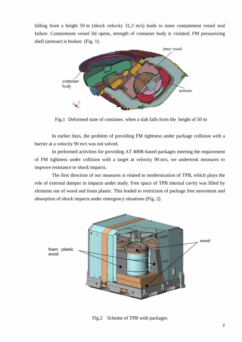
falling from a height 50 m (shock velocity 31,3 m/s) leads to inner containment vessel seal
failure. Containment vessel lid opens, strength of container body is violated, FM pressurizing
shell (armour) is broken (Fig. 1).
Fig.1 Deformed state of container, when a slab falls from the height of 50 m
In earlier days, the problem of providing FM tightness under package collision with a
barrier at a velocity 90 m/s was not solved.
In performed activities for providing АТ 400R-based packages meeting the requirement
of FM tightness under collision with a target at velocity 90 m/s, we undertook measures to
improve resistance to shock impacts.
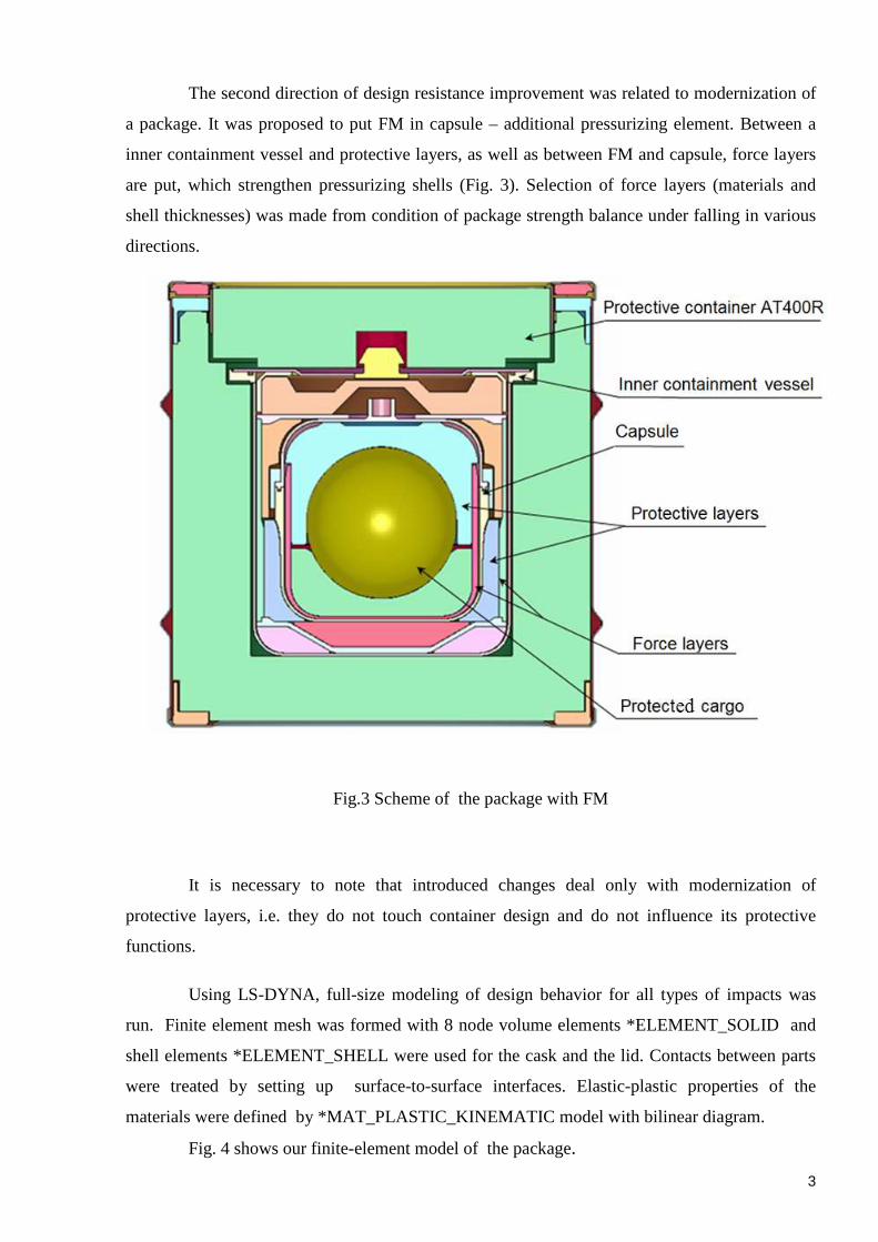
The first direction of our measures is related to modernization of TPB, which plays the
role of external damper in impacts under study. Free space of TPB internal cavity was filled by
elements out of wood and foam plastic. This leaded to restriction of package free movement and
absorption of shock impacts under emergency situations (Fig. 2).
Fig.2 Scheme of TPB with packages
3
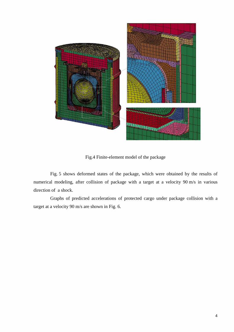
The second direction of design resistance improvement was related to modernization of
a package. It was proposed to put FM in capsule – additional pressurizing element. Between a
inner containment vessel and protective layers, as well as between FM and capsule, force layers
are put, which strengthen pressurizing shells (Fig. 3). Selection of force layers (materials and
shell thicknesses) was made from condition of package strength balance under falling in various
directions.
Fig.3 Scheme of the package with FM
It is necessary to note that introduced changes deal only with modernization of
protective layers, i.e. they do not touch container design and do not influence its protective
functions.
Using LS-DYNA, full-size modeling of design behavior for all types of impacts was
run. Finite element mesh was formed with 8 node volume elements *ELEMENT_SOLID and
shell elements *ELEMENT_SHELL were used for the cask and the lid. Contacts between parts
were treated by setting up surface-to-surface interfaces. Elastic-plastic properties of the
materials were defined by *MAT_PLASTIC_KINEMATIC model with bilinear diagram.
Fig. 4 shows our finite-element model of the package.
4
Fig.4 Finite-element model of the package
Fig. 5 shows deformed states of the package, which were obtained by the results of
numerical modeling, after collision of package with a target at a velocity 90 m/s in various
direction of a shock.
Graphs of predicted accelerations of protected cargo under package collision with a
target at a velocity 90 m/s are shown in Fig. 6.

5
a) container bottom residual deformation in capsule – 15%
b) container side surface residual deformation in capsule – 19%
c) container lid residual deformation in capsule – 20%
d) container corner residual deformation in capsule – 20%
Fig. 5 Package collision with a target at a velocity 90 m/s
Fig. 6 PC accelerations under package collision with a target at a velocity 90 m/s
6
According to the results of numerical modeling, a conclusion was made that maximum
damage of package sealing system is made in case of target contact with container side surface.
Maximum deformations in capsule are concentrated in the region of pressurizing joint – in lock
joint zone.
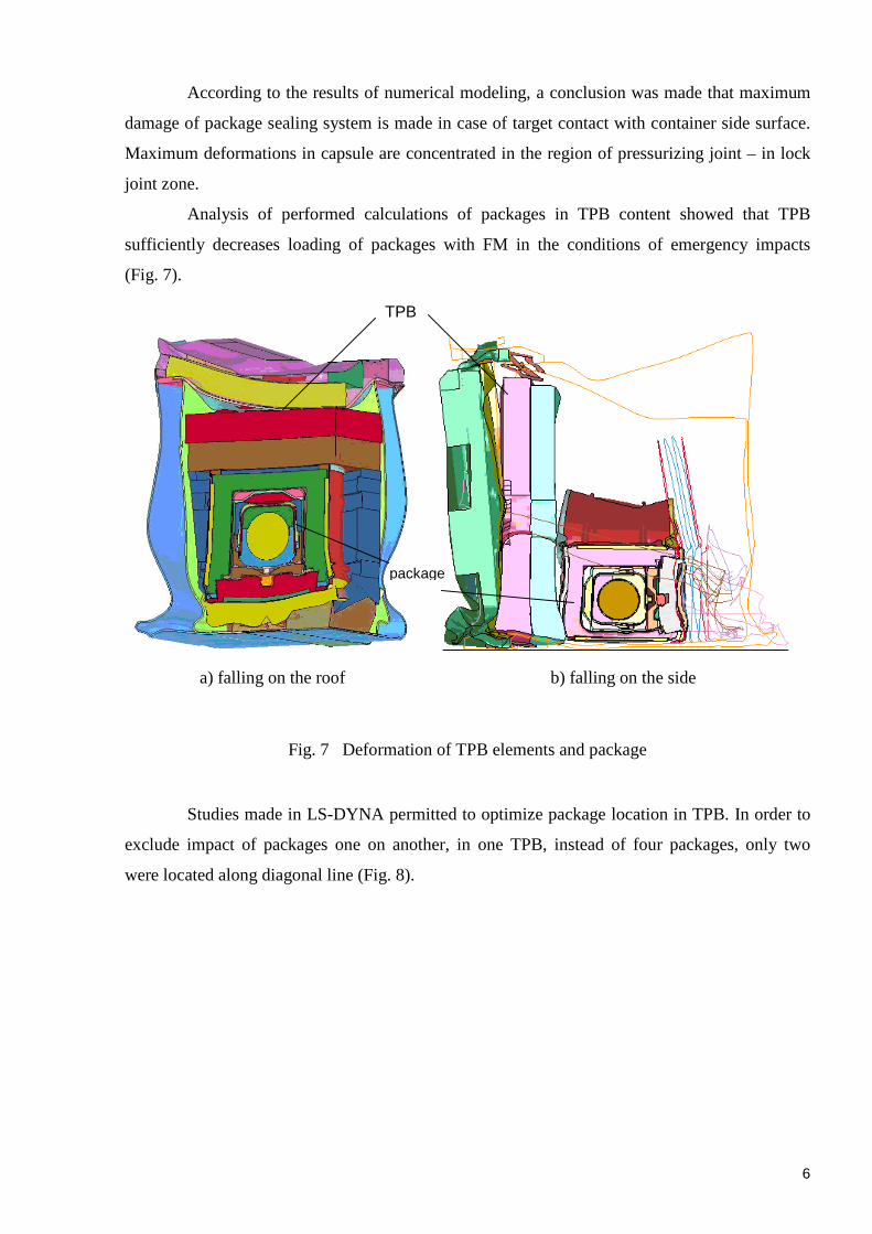
Analysis of performed calculations of packages in TPB content showed that TPB
sufficiently decreases loading of packages with FM in the conditions of emergency impacts
(Fig. 7).
a) falling on the roof b) falling on the side
Fig. 7 Deformation of TPB elements and package
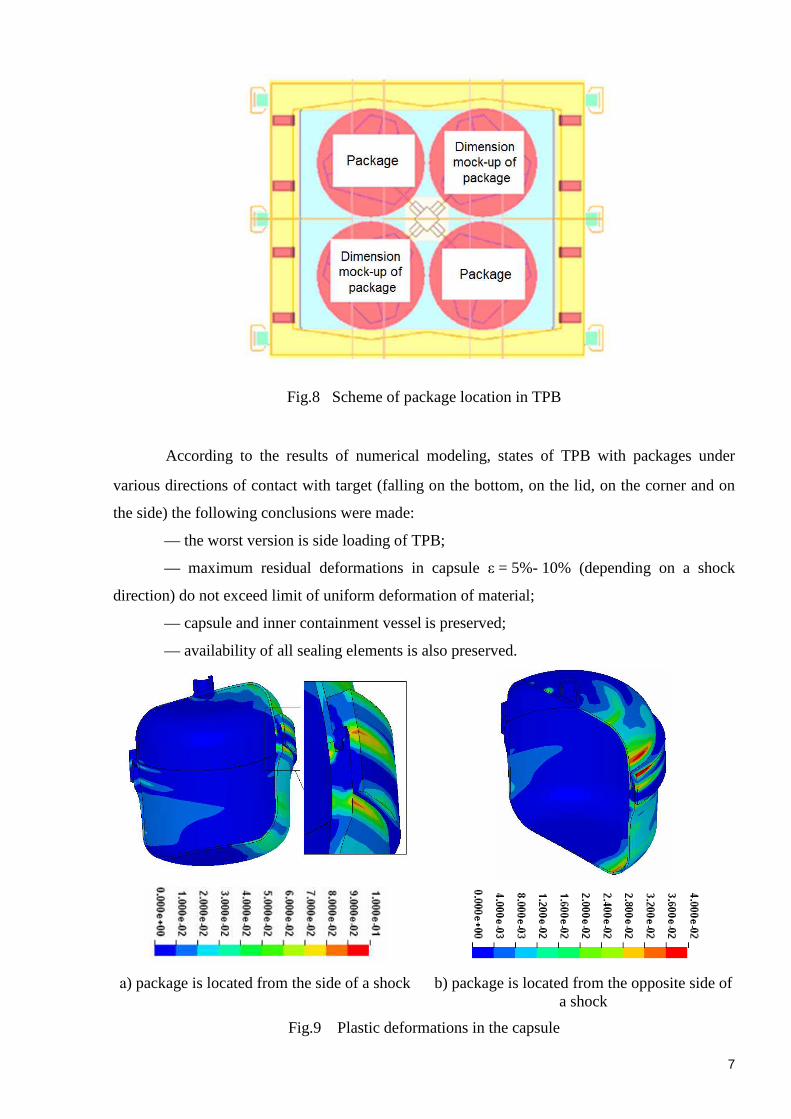
Studies made in LS-DYNA permitted to optimize package location in TPB. In order to
exclude impact of packages one on another, in one TPB, instead of four packages, only two
were located along diagonal line (Fig. 8).
package
TPB
7
Fig.8 Scheme of package location in TPB
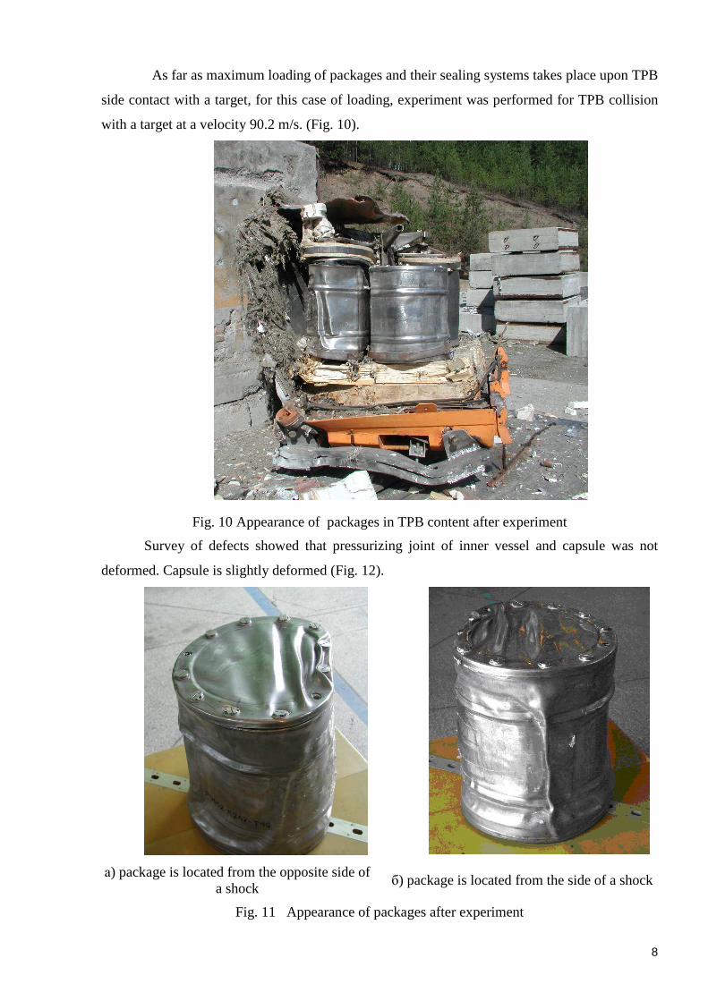
According to the results of numerical modeling, states of TPB with packages under
various directions of contact with target (falling on the bottom, on the lid, on the corner and on
the side) the following conclusions were made:
— the worst version is side loading of TPB;
— maximum residual deformations in capsule ε = 5%- 10% (depending on a shock
direction) do not exceed limit of uniform deformation of material;
— capsule and inner containment vessel is preserved;
— availability of all sealing elements is also preserved.
а) package is located from the side of a shock b) package is located from the opposite side of a shock
Fig.9 Plastic deformations in the capsule
8
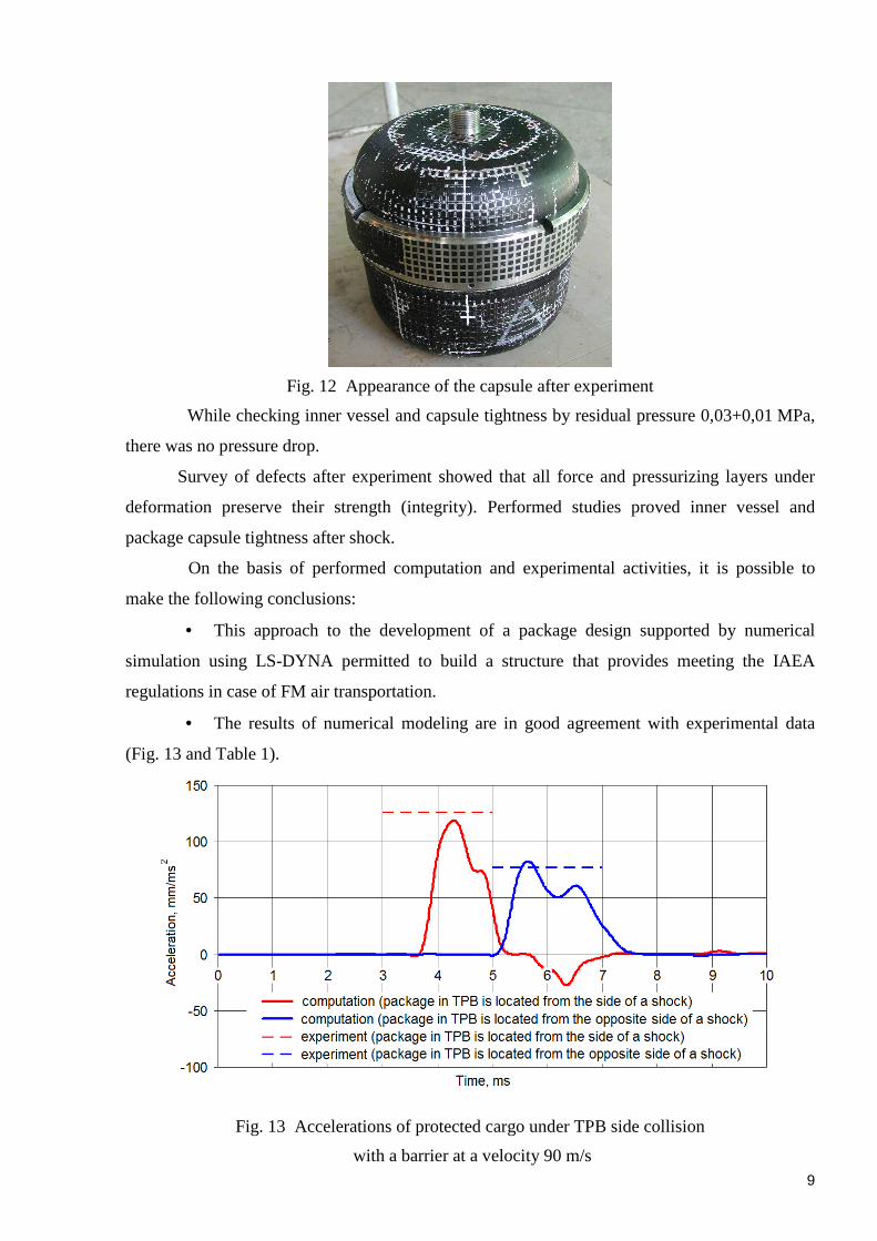
As far as maximum loading of packages and their sealing systems takes place upon TPB
side contact with a target, for this case of loading, experiment was performed for TPB collision
with a target at a velocity 90.2 m/s. (Fig. 10).
Fig. 10 Appearance of packages in TPB content after experiment
Survey of defects showed that pressurizing joint of inner vessel and capsule was not
deformed. Capsule is slightly deformed (Fig. 12).
а) package is located from the opposite side of a shock
б) package is located from the side of a shock
Fig. 11 Appearance of packages after experiment
9
Fig. 12 Appearance of the capsule after experiment
While checking inner vessel and capsule tightness by residual pressure 0,03+0,01 MPa,
there was no pressure drop.
Survey of defects after experiment showed that all force and pressurizing layers under
deformation preserve their strength (integrity). Performed studies proved inner vessel and
package capsule tightness after shock.
On the basis of performed computation and experimental activities, it is possible to
make the following conclusions:
• This approach to the development of a package design supported by numerical
simulation using LS-DYNA permitted to build a structure that provides meeting the IAEA
regulations in case of FM air transportation.
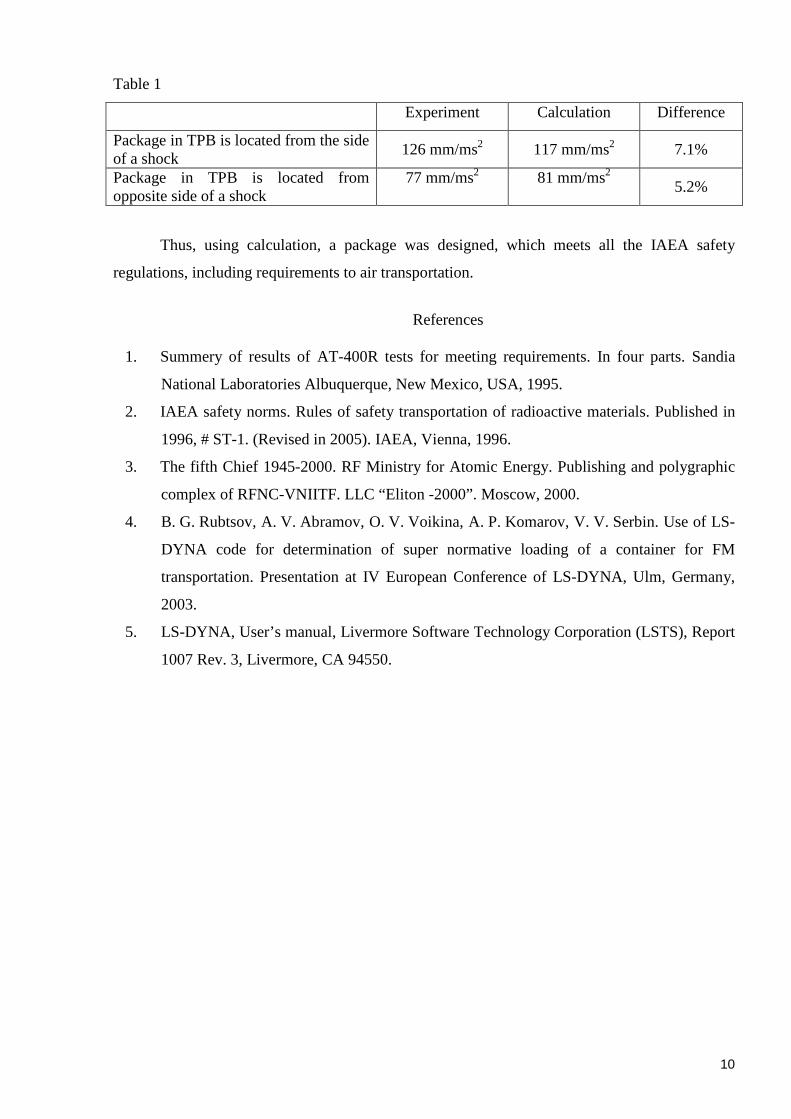
• The results of numerical modeling are in good agreement with experimental data
(Fig. 13 and Table 1).
Fig. 13 Accelerations of protected cargo under TPB side collision
with a barrier at a velocity 90 m/s
10
Table 1
Experiment Calculation Difference
Package in TPB is located from the side of a shock
126 mm/ms2 117 mm/ms2 7.1%
Package in TPB is located from opposite side of a shock
77 mm/ms2
81 mm/ms2
5.2%
Thus, using calculation, a package was designed, which meets all the IAEA safety
regulations, including requirements to air transportation.
References
1. Summery of results of AT-400R tests for meeting requirements. In four parts. Sandia
National Laboratories Albuquerque, New Mexico, USA, 1995.
2. IAEA safety norms. Rules of safety transportation of radioactive materials. Published in
1996, # ST-1. (Revised in 2005). IAEA, Vienna, 1996.
3. The fifth Chief 1945-2000. RF Ministry for Atomic Energy. Publishing and polygraphic
complex of RFNC-VNIITF. LLC “Eliton -2000”. Moscow, 2000.
4. B. G. Rubtsov, A. V. Abramov, O. V. Voikina, A. P. Komarov, V. V. Serbin. Use of LS-
DYNA code for determination of super normative loading of a container for FM
transportation. Presentation at IV European Conference of LS-DYNA, Ulm, Germany,
2003.
5. LS-DYNA, User’s manual, Livermore Software Technology Corporation (LSTS), Report
1007 Rev. 3, Livermore, CA 94550.