autosketch 10 advanced exercises -...
TRANSCRIPT
October 2008
AutoSketch 10Advanced Exercises
®

© 2008 Autodesk, Inc. All rights reserved. Except as otherwise permitted by Autodesk, Inc., this publication, or parts thereof, maynot be reproduced in any form, by any method, for any purpose.
Certain materials included in this publication are reprinted with the permission of the copyright holder.
Trademarks
The following are registered trademarks or trademarks of Autodesk, Inc., in the USA and other countries: 3DEC (design/logo),3December, 3December.com, 3ds Max, ADI, Alias, Alias (swirl design/logo), AliasStudio, Alias|Wavefront (design/logo), ATC, AUGI,AutoCAD, AutoCAD Learning Assistance, AutoCAD LT, AutoCAD Simulator, AutoCAD SQL Extension, AutoCAD SQL Interface,Autodesk, Autodesk Envision, Autodesk Insight, Autodesk Intent, Autodesk Inventor, Autodesk Map, Autodesk MapGuide, AutodeskStreamline, AutoLISP, AutoSnap, AutoSketch, AutoTrack, Backdraft, Built with ObjectARX (logo), Burn, Buzzsaw, CAiCE, Can YouImagine, Character Studio, Cinestream, Civil 3D, Cleaner, Cleaner Central, ClearScale, Colour Warper, Combustion, CommunicationSpecification, Constructware, Content Explorer, Create>what's>Next> (design/logo), Dancing Baby (image), DesignCenter, DesignDoctor, Designer's Toolkit, DesignKids, DesignProf, DesignServer, DesignStudio, Design|Studio (design/logo), Design Web Format,DWF, DWG, DWG (logo), DWG Extreme, DWG TrueConvert, DWG TrueView, DXF, Ecotect, Exposure, Extending the Design Team,FBX, Filmbox, FMDesktop, Freewheel, GDX Driver, Gmax, Green Building Studio, Heads-up Design, Heidi, HumanIK, IDEA Server, i-drop, ImageModeler, iMOUT, Incinerator, Inventor, Inventor LT, Kaydara, Kaydara (design/logo), Kynapse, Kynogon, LandXplorer,LocationLogic, Lustre, Matchmover, Maya, Mechanical Desktop, MotionBuilder, Movimento, Mudbox, NavisWorks, ObjectARX,ObjectDBX, Open Reality, Opticore, Opticore Opus, PolarSnap, PortfolioWall, Powered with Autodesk Technology, Productstream,ProjectPoint, ProMaterials, RasterDWG, Reactor, RealDWG, Real-time Roto, REALVIZ, Recognize, Render Queue, Retimer,Reveal, Revit,Showcase, ShowMotion, SketchBook, SteeringWheels, Stitcher, StudioTools, Topobase, Toxik, TrustedDWG, ViewCube, Visual, VisualConstruction, Visual Drainage, Visual Landscape, Visual Survey, Visual Toolbox, Visual LISP, Voice Reality, Volo, Vtour, Wiretap, andWiretapCentral.
The following are registered trademarks or trademarks of Autodesk Canada Co. in the USA and/or Canada and other countries:Backburner, Discreet, Fire, Flame, Flint, Frost, Inferno, Multi-Master Editing, River, Smoke, Sparks, Stone, and Wire.
The following are registered trademarks or trademarks of Moldflow Corp. in the USA and/or other countries: Moldflow
MPA, MPA (design/logo), Moldflow Plastics Advisers, MPI, MPI (design/logo), Moldflow Plastics Insight, MPX, MPX (design/logo),Moldflow Plastics Xpert.
All other brand names, product names or trademarks belong to their respective holders.
Disclaimer
THIS PUBLICATION AND THE INFORMATION CONTAINED HEREIN IS MADE AVAILABLE BY AUTODESK, INC. "AS IS." AUTODESK, INC.,DISCLAIMS ALL WARRANTIES, EITHER EXPRESS OR IMPLIED, INCLUDING BUT NOT LIMITED TO ANY IMPLIED WARRANTIES OFMERCHANTABILITY OR FITNESS FOR A PARTICULAR PURPOSE REGARDING THESE MATERIALS.
Published by:
Autodesk, Inc. 111 Mclnnis Parkway San Rafael, CA 94903, USA
Tutorial 4 — Advanced Exercises
In this tutorial
■ Create 3D Effects
■ Use Web Tools
■ Generate a Database Report
In this tutorial, you learn how to create 3D effects, use
the Web tools called eTransmit, hyperlinks, and gener-
ate a database report.
More information about each of the concepts in this
tutorial is available in the AutoSketch® Help system.
1
Create 3D Effects
In this exercise, you learn to
❒ Create a 3D parallel extrusion.❒ Use the Standard toolbar.❒ Use the 3D Effects toolbar.
While two-dimensional drawings are the basic building blocks of most projects, you might need a three-dimensional view of a project. In AutoSketch, you can simulate three-dimensional drawings through parallel and perspective extrusion.
■ 3D parallel extrusion creates a copy of the selection set that you place in the drawing. AutoSketch connects corresponding edges with lines or poly-gons. You learn how to create a 3D parallel extrusion in this exercise.
■ 3D perspective extrusion creates a scaled copy of the selection set. You place the copy anywhere in the drawing, and AutoSketch connects the corresponding edges using lines or polygons.
To apply parallel extrusion to an entity
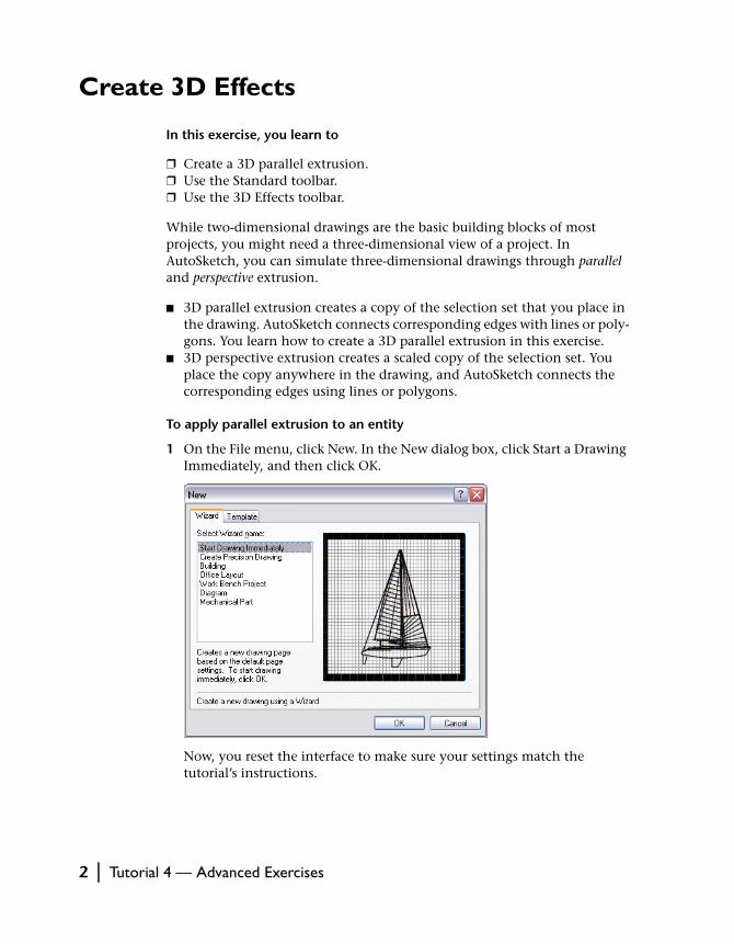
1 On the File menu, click New. In the New dialog box, click Start a Drawing Immediately, and then click OK.
Now, you reset the interface to make sure your settings match the tutorial’s instructions.
2 | Tutorial 4 — Advanced Exercises
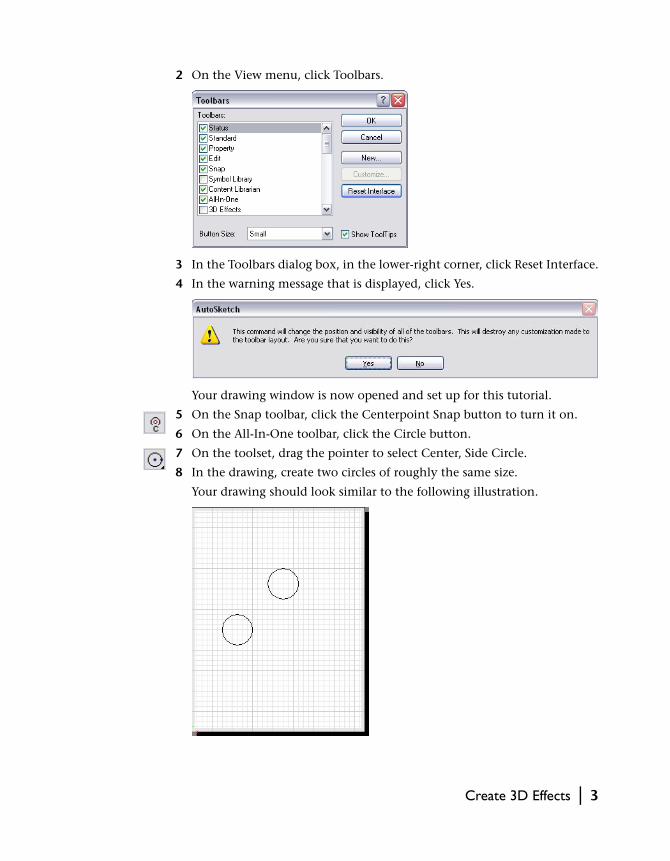
2 On the View menu, click Toolbars.
3 In the Toolbars dialog box, in the lower-right corner, click Reset Interface.
4 In the warning message that is displayed, click Yes.
Your drawing window is now opened and set up for this tutorial.
5 On the Snap toolbar, click the Centerpoint Snap button to turn it on.
6 On the All-In-One toolbar, click the Circle button.
7 On the toolset, drag the pointer to select Center, Side Circle.
8 In the drawing, create two circles of roughly the same size.
Your drawing should look similar to the following illustration.
Create 3D Effects | 3

9 On the Standard toolbar, click the 3D Effects button.
The 3D Effects toolbar is displayed.
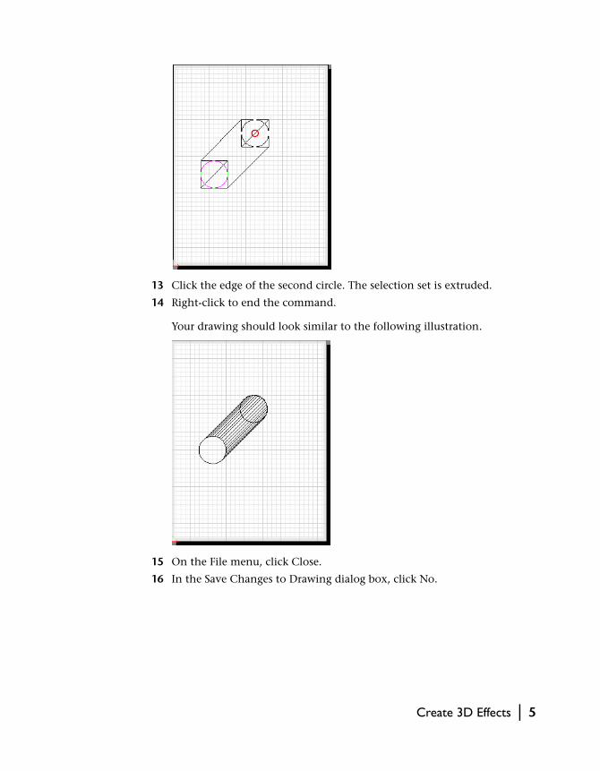
10 Click the circle that is closer to the bottom of the drawing.
11 On the 3D Effects toolbar, click the 3D Parallel Extrusion button.
12 In the drawing, click the bottom circle again.
This is the first of two points that define the distance and direction that the selection set will be extruded. A rubber-band extrusion appears and moves the same distance and direction as the pointer.
4 | Tutorial 4 — Advanced Exercises
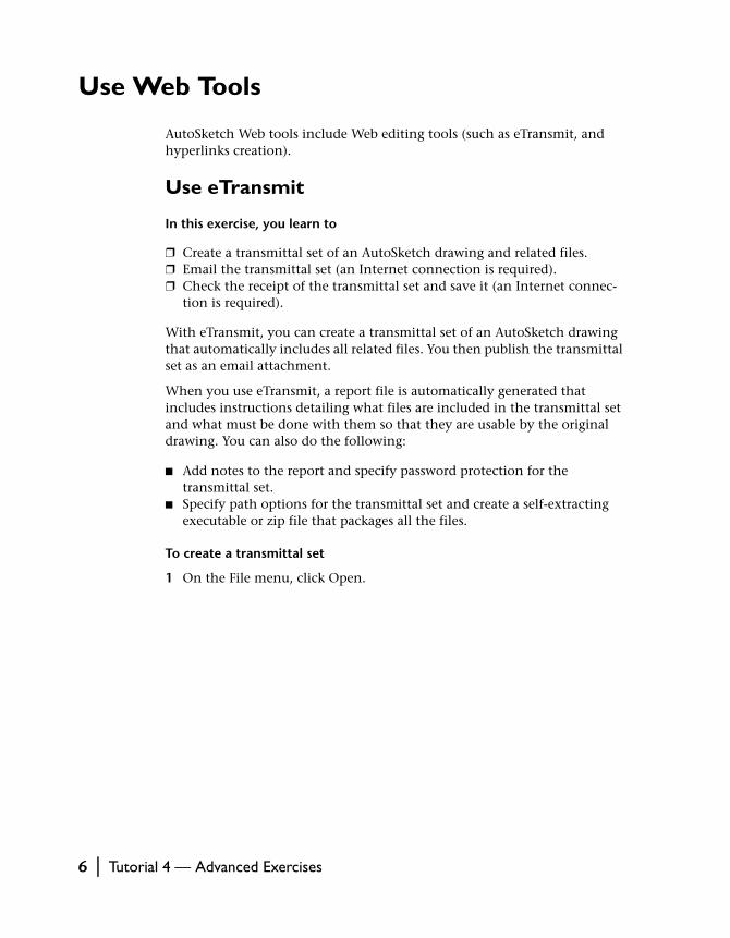
13 Click the edge of the second circle. The selection set is extruded.
14 Right-click to end the command.
Your drawing should look similar to the following illustration.
15 On the File menu, click Close.
16 In the Save Changes to Drawing dialog box, click No.
Create 3D Effects | 5
Use Web Tools
AutoSketch Web tools include Web editing tools (such as eTransmit, and hyperlinks creation).
Use eTransmit
In this exercise, you learn to
❒ Create a transmittal set of an AutoSketch drawing and related files.❒ Email the transmittal set (an Internet connection is required).❒ Check the receipt of the transmittal set and save it (an Internet connec-
tion is required).
With eTransmit, you can create a transmittal set of an AutoSketch drawing that automatically includes all related files. You then publish the transmittal set as an email attachment.
When you use eTransmit, a report file is automatically generated that includes instructions detailing what files are included in the transmittal set and what must be done with them so that they are usable by the original drawing. You can also do the following:
■ Add notes to the report and specify password protection for the transmittal set.
■ Specify path options for the transmittal set and create a self-extracting executable or zip file that packages all the files.
To create a transmittal set
1 On the File menu, click Open.
6 | Tutorial 4 — Advanced Exercises
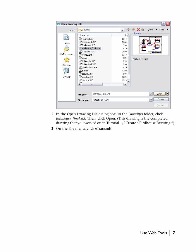
2 In the Open Drawing File dialog box, in the Drawings folder, click Birdhouse_final.skf. Then, click Open. (This drawing is the completed drawing that you worked on in Tutorial 1, “Create a Birdhouse Drawing.”)
3 On the File menu, click eTransmit.
Use Web Tools | 7
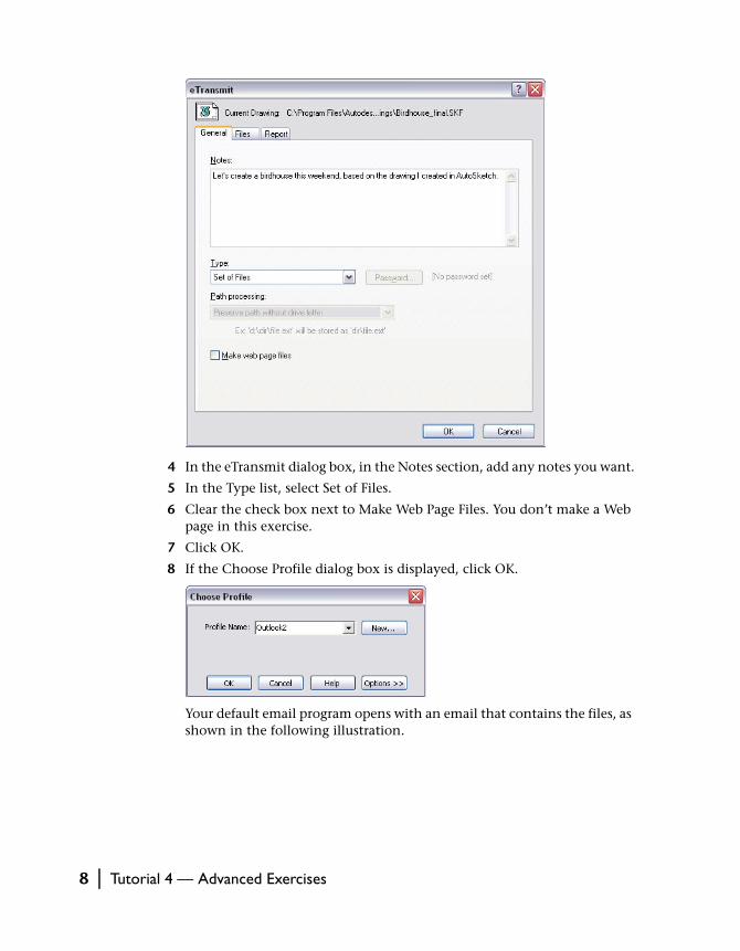
4 In the eTransmit dialog box, in the Notes section, add any notes you want.
5 In the Type list, select Set of Files.
6 Clear the check box next to Make Web Page Files. You don’t make a Web page in this exercise.
7 Click OK.
8 If the Choose Profile dialog box is displayed, click OK.
Your default email program opens with an email that contains the files, as shown in the following illustration.
8 | Tutorial 4 — Advanced Exercises
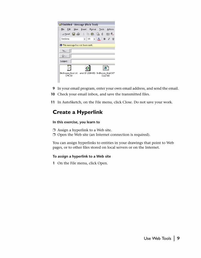
9 In your email program, enter your own email address, and send the email.
10 Check your email inbox, and save the transmitted files.
11 In AutoSketch, on the File menu, click Close. Do not save your work.
Create a Hyperlink
In this exercise, you learn to
❒ Assign a hyperlink to a Web site.❒ Open the Web site (an Internet connection is required).
You can assign hyperlinks to entities in your drawings that point to Web pages, or to other files stored on local servers or on the Internet.
To assign a hyperlink to a Web site
1 On the File menu, click Open.
Use Web Tools | 9
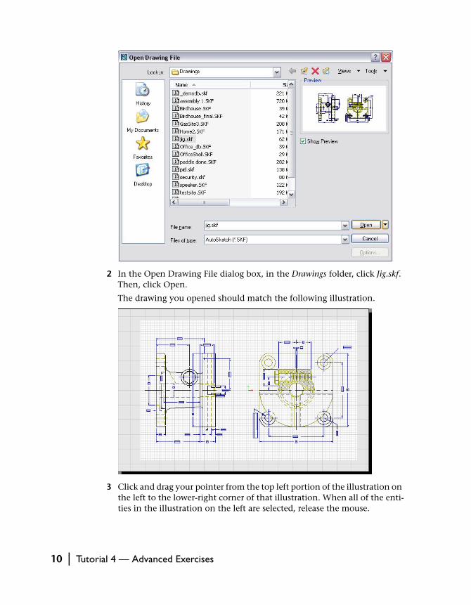
2 In the Open Drawing File dialog box, in the Drawings folder, click Jig.skf. Then, click Open.
The drawing you opened should match the following illustration.
3 Click and drag your pointer from the top left portion of the illustration on the left to the lower-right corner of that illustration. When all of the enti-ties in the illustration on the left are selected, release the mouse.
10 | Tutorial 4 — Advanced Exercises
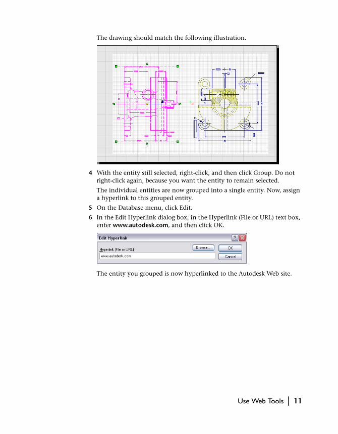
The drawing should match the following illustration.
4 With the entity still selected, right-click, and then click Group. Do not right-click again, because you want the entity to remain selected.
The individual entities are now grouped into a single entity. Now, assign a hyperlink to this grouped entity.
5 On the Database menu, click Edit.
6 In the Edit Hyperlink dialog box, in the Hyperlink (File or URL) text box, enter www.autodesk.com, and then click OK.
The entity you grouped is now hyperlinked to the Autodesk Web site.
Use Web Tools | 11
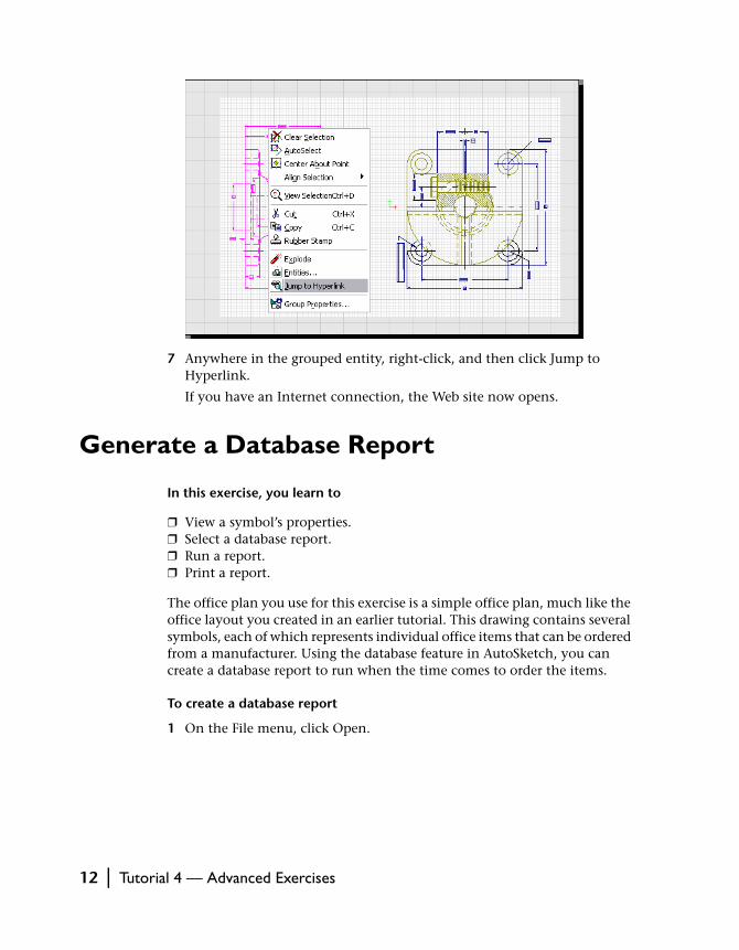
7 Anywhere in the grouped entity, right-click, and then click Jump to Hyperlink.
If you have an Internet connection, the Web site now opens.
Generate a Database Report
In this exercise, you learn to
❒ View a symbol’s properties.❒ Select a database report.❒ Run a report.❒ Print a report.
The office plan you use for this exercise is a simple office plan, much like the office layout you created in an earlier tutorial. This drawing contains several symbols, each of which represents individual office items that can be ordered from a manufacturer. Using the database feature in AutoSketch, you can create a database report to run when the time comes to order the items.
To create a database report
1 On the File menu, click Open.
12 | Tutorial 4 — Advanced Exercises
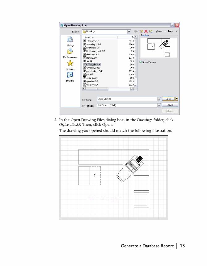
2 In the Open Drawing Files dialog box, in the Drawings folder, click Office_db.skf. Then, click Open.
The drawing you opened should match the following illustration.
Generate a Database Report | 13
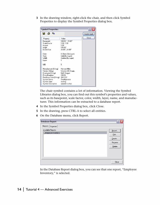
3 In the drawing window, right-click the chair, and then click Symbol Properties to display the Symbol Properties dialog box.
The chair symbol contains a lot of information. Viewing the Symbol Libraries dialog box, you can find out this symbol’s properties and values, such as its basepoint, scale factor, color, width, layer, name, and manufac-turer. This information can be extracted to a database report.
4 In the Symbol Properties dialog box, click Close.
5 In the drawing, press CTRL-A to select all entities.
6 On the Database menu, click Report.
In the Database Report dialog box, you can see that one report, “Employee Inventory,” is selected.
14 | Tutorial 4 — Advanced Exercises
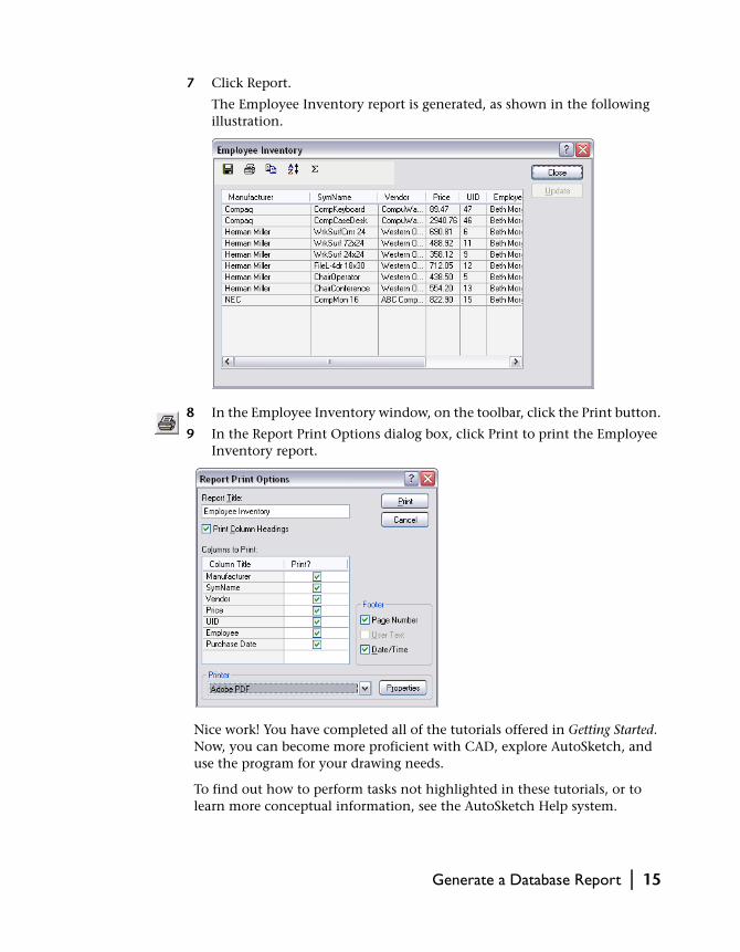
7 Click Report.
The Employee Inventory report is generated, as shown in the following illustration.
8 In the Employee Inventory window, on the toolbar, click the Print button.
9 In the Report Print Options dialog box, click Print to print the Employee Inventory report.
Nice work! You have completed all of the tutorials offered in Getting Started. Now, you can become more proficient with CAD, explore AutoSketch, and use the program for your drawing needs.
To find out how to perform tasks not highlighted in these tutorials, or to learn more conceptual information, see the AutoSketch Help system.
Generate a Database Report | 15

16 | Tutorial 4 — Advanced Exercises