autonomous optimization of casting processes and … · world foundry congress, hangzhou, china in...
TRANSCRIPT
World Foundry Congress, Hangzhou, China in October 16-20, 2010
Autonomous optimization of casting processes and designs
Ingo Hahn* and Jörg C. Sturm* Abstract Twenty years after the introduction of simulation software for foundries into the industry, casting process simulation has become an accepted tool for process and design lay-out. Casting process simulation always displays the status quo of its expert user. The user decides if the rigging system or process parameters lead to an acceptable result. Additionally, proposals for optimized solutions have to come from the operator. One of the biggest benefits of the casting process is also its biggest downfall: Everything happens at the same time and is coupled. Changes in one process parameter impact many casting quality defining features during the process. Multi-objective autonomous optimization offers a way out. Autonomous optimization uses the simulation tool as a virtual experimentation field and changes pouring conditions, gating designs or process parameters and this way tries to find the optimal route to fulfill the desired objective. Several parameters can be changed and evaluated independently from each other. Autonomous optimization tools take the classic approach of foundry engineers, to find the best compromise and use validated physics. This not only further reduces the need for trial runs to find the optimal process window, but allows the detailed evaluation of many process parameters and their individual impact on providing a robust process. Obviously, what can be simulated can be optimized. Optimization, therefore, is not a replacement for process knowledge and expertise. Despite beliefs to the contrary, the simulation user of the future needs to know the objectives and goals, and especially the quality criteria that are needed to reach these goals. The questions to ask a program are easy: What is a good gating system? To answer this question, quantitative solutions are required. An old foundry man’s dream is becoming reality: trial and error is not performed on the shop floor but on the computer. The foundry man defines his optimization goals and can evaluate the best possible solution. He also receives quantitative information about the sensitivity of important process parameters and can assess the robustness of his designs. The paper will give an overview on the state of the art of virtual autonomous optimization on selected industrial examples. Keywords: Casting process simulation – Optimization – Genetic Algorithms – DoE – robust Processes *MAGMA Gießereitechnologie GmbH, Aachen Germany
World Foundry Congress, Hangzhou, China in October 16-20, 2010
INTRODUCTION Twenty years after the introduction of simulation software for foundries into the industry, casting process simulation has become an accepted tool for process and design lay-out. Casting process simulation always displays the status quo of its expert user. Based on available simulation results, the user decides if the rigging system or process parameters will lead to an acceptable result. The proposal for an optimized solution has to come from the foundry man. Due to the multitude of factors affecting the quality of castings and the complex interactions of physics, metallurgy and casting geometry, empirical knowledge is the main source on which “optimized manufacturing engineering” is based. Foundry simulation can quantify experience and therefore testis more than a defined “state” or lay-out. It provides insights into the root causes of problems. The individual simulation does not tell the expert how robust his design will be. The decision about measures to improve a certain lay-out or process setup might be based on the simulation results but essentially require the expertise and judgment of an expert. This means that a continuous improvement involves “trial and error” – both in reality and in simulation. As an important step to reduce the efforts caused by “trial and error”, statistical methods were developed to efficiently plan experiments. The aim of these Design of Experiments (DoE) methods is to achieve valuable information with a reduced number of tests [1,2]. The methods are based on statistical theory and are to be applied in cases where the influence of a number of parameters on a measured outcome needs to be explored. They have been applied successfully for real world experiments but also offer substantial benefits if used in conjunction with simulation runs [3]. Although the application of DoE methods often is an important step to develop an optimized casting process, the foundry expert has a strong focus on his particular technical problems so that in many cases an optimization approach with even less interaction is demanded. In recent years the usage of simulation software has improved and now integrates parallel processing computers. One virtual casting experiment can often be completed within a few minutes. Combining simulation software with an optimization program makes it possible to automatically analyze different calculated designs with respect to the defined objectives (e.g. low porosity and low rate of returns). Based on the outcome, the software will create new designs and will analyze them in the same way. Autonomous optimization uses the simulation tool as a virtual experimentation or test field. By modifying pouring conditions, gating designs or process parameters, the software tries to find the optimal route to fulfill the desired objective. Several parameters can be changed at the same time and be evaluated independently from each other. Autonomous optimization tools combine the classical approach of foundry engineers, to find the “best compromise” with validated physics. This not only further reduces the need for trial runs to find the optimal process window, but also allows the in-depth evaluation of many process parameters and their individual impact on providing a robust process.

World Foundry Congress, Hangzhou, China in October 16-20, 2010
THE CLASSIC OPTIMIZATION OF THE CASTING PROCESS – THE "ONE-DIMENSIONAL SEARCH" Every foundry is constantly improving its processes. The goal is to either increase the quality of castings while keeping the required profitability of the process or vice versa. Usually a simple optimization approach is applied: Through sequential trials, reviews and linear, step-wise improvements of individual input parameters, an acceptable process configuration - a compromise - might eventually be reached. Unfortunately, nobody knows if this process configuration represents a true optimum and how big the process window for it is. Example: For the development of a rigging system for a steel casting, the first version of a design (the gating system, risers, chills and other feeding aids) is determined by the foundry expert. This initial, experience based approach is then evaluated through simulation. Problems are identified, which leads to a change in the layout, again based on experience. This process is repeated as often as necessary until the desired casting quality is realized, Fig. 1 [4].
Fig. 1: The one-dimensional search (left) is the standard process to optimize a casting process layout. The expert performs an optimization by himself, as he provides process layouts as well as evaluates and modifies them until he is satisfied. In a Design of Experiments (center), however, all parameter combinations are provided at the beginning of the process and are all evaluated together at the end of the calculations. In the autonomous optimization (right), process parameter combinations will be configured based on previously run simulations and experience an optimization loop to determine the optimal layout. The "one-dimensional search" is characterized by a limited number of trials, with the risk of getting trapped in a dead-end. Proposed solutions are usually not tested with respect to their borders. The "one-dimensional search" additionally faces another drawback: the ability to transfer gained knowledge from the current to new projects is limited with increasing casting or process complexity. At the same time, the requirements on productivity and robustness of the production process increase constantly. Financial necessities require accurate planning of the casting concept and the manufacturing process. There is an urgent necessity to eliminate the trial-and-error factor for the user. DESIGN OF EXPERIMENTS IN SIMULATION Design of Experiment (DoE) methods have been used for a long time for the optimization of manufacturing processes. DoE set-ups are configured and evaluated using statistical methods [1,2]. In a virtual DoE, real experiments are replaced by a number of simulation runs. The goal of a DoE is to evaluate the impact of each process parameter on the casting process in order to predict its impact on the investigated or measured objective at any point of the process window. A minimum number of experiments must be used to find critical parameters influencing the final objectives, i.e. casting quality or manufacturing costs. In the following steel casting example, the number, location and

World Foundry Congress, Hangzhou, China in October 16-20, 2010
dimensioning of feeders and chills are investigated with respect to their impact on the shrinkage distribution in the casting, Fig. 2.
Fig. 2: Ring shaped steel casting with feeders and chills in the cope (left) and drag (right). This initial number of feeders and chills are related to each other as the chills are always positioned between the feeders – this is the basis for all explored variations of the process, see below.

World Foundry Congress, Hangzhou, China in October 16-20, 2010
The user defines the upper and lower limits for each process parameter varied (i.e. number of feeders is allowed to be between 5 and 10 – the number of chills is related to that). The DoE is then developed based on statistical patterns, after which the required simulations will be started. With the use of optimization algorithms, a simulation sequence can be established and then automatically be performed without interference by the user. Precondition for the automatic procedure is that the geometry of the simulation model is defined by parametric geometries that can be modified automatically. Additionally, with each geometrical modification proposed by the algorithm, the software must be able to automatically remesh the new design in seconds. After all of the simulations have been finished, the operator can evaluate the results according to his objectives - in this case, the level of shrinkage defects in combination with the highest casting yield. The operator can easily find out which parameters have the biggest impact on the objectives. Based on the results of a DoE an efficient optimization of the objectives can be achieved. The less the real behavior of the process layout is known, the more important it is to cover the entire area of meaningful and essential process parameter changes. The user always has the option to take advantage of his casting process knowledge. The use of experiential knowledge in combination with mathematically based methods of DoE's quickly leads to good results, even when multiple variables need to be considered. AUTONOMOUS COMPUTERIZED OPTIMIZATION When autonomous optimization is utilized, the operator defines not only the degrees of freedom for the process parameters but also the objectives before the simulations are performed. Several even contradictory objectives can be pursued at the same time (e.g. casting quality, productivity, material input). The optimization program automatically performs a first group of simulations (1st generation). Following the calculation of each generation, the program automatically evaluates the results according to the objectives defined by the operator. Then, dependent on the simulation results and the chosen objectives, a genetic algorithm creates new variations of the gating and feeder layout. This procedure follows the rules of evolution: Each time it is decided if a layout variation is kept, eliminated or modified – or if it is combined with an already calculated or new design. This process is repeated until design modifications do not lead to additional improvements. Just as in the biological world, this process happens over several (calculation-) generations. With this method it is possible to work on multiple, potentially conflicting goals (i.e. casting quality, productivity, and material usage). To achieve the desired objectives, process parameters such as pouring temperature, alloying elements, mold preheating, as well as geometries (gating design, ingates, feeder dimensions) can be varied. Autonomous optimization is a very powerful tool to find the best process layout for any casting process. The simulation program replaces the R&D foundry as this method is usable without restrictions. In the last years, autonomous optimization has been applied to most fields in casting technology [5,6,7].
World Foundry Congress, Hangzhou, China in October 16-20, 2010
It must be acknowledged that this methodology often leads to a large number of simulations. Complex process-related objectives often require a number of generations to be calculated before a reasonable solution is reached. However, the progress in computer technology enables autonomous optimization to establish itself as a valuable tool if it is combined with a pragmatic engineering approach. If only limited hardware capabilities are available to simulate complex casting processes without doing reasonable simplifications, it is recommended to use the more effective approach of virtual DoE's.
OPTIMIZED CASTING OF A BIG STEELPART
The process of a virtual DoE is explored by using the feeder and chill layout of a steel casting. The idea is to find an optimal combination of feeders and chills on the perimeter of the casting, Fig, 2. The following variations are allowed and should be evaluated: Number of feeders 5, 6, 7, 8, 9, 10 Size of feeders Type 1 – 10 Length of chills in drag 50, 60, 70, 80, 90, 100, 110, 120,
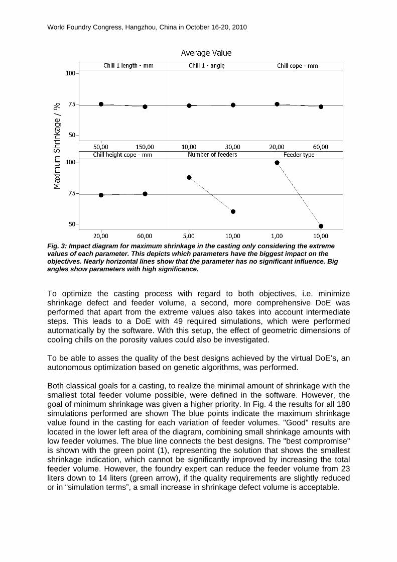
130, 140, 150 (mm) Swept angle of drag chills 10, 15, 20, 25, 30 ° Diameter of chills in cope 20, 30, 40, 50, 60 (mm) Height of cope chills 20, 30, 40, 50, 60 (mm) Table 1: Variations and degrees of freedom for the autonomous optimization The evaluation of all possible variations (designs) would require the investigation of 82,500 cases. To identify the essential reaction of the casting process to casting process parameter changes, DoE's only focus on the extreme input values. A complete DoE for 6 variables therefore leads to 64 simulations, which in this case could further be reduced down to 16 simulations being sufficient to depict the most important variables. Fig. 3 shows which parameters will have the biggest impact on shrinkage defects in the casting for each of the six selected process parameters. Not surprisingly the number and type of feeders has the biggest impact on the casing quality. During the first screening of process parameters, a significant impact of the chill size could not be detected. The effect of changing the number of feeders (and hence also the number of chills) dominates the effect of changing the size of chills within the given range.
World Foundry Congress, Hangzhou, China in October 16-20, 2010
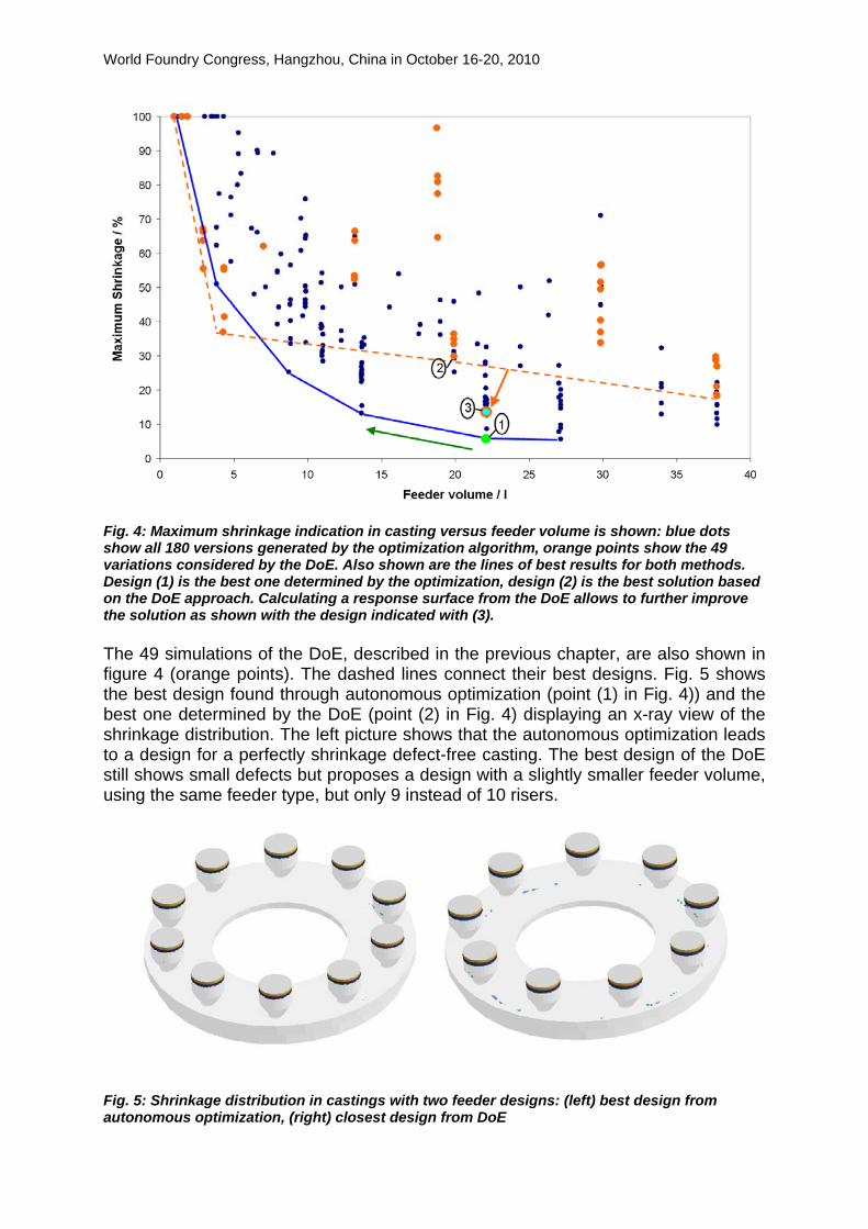
Fig. 3: Impact diagram for maximum shrinkage in the casting only considering the extreme values of each parameter. This depicts which parameters have the biggest impact on the objectives. Nearly horizontal lines show that the parameter has no significant influence. Big angles show parameters with high significance. To optimize the casting process with regard to both objectives, i.e. minimize shrinkage defect and feeder volume, a second, more comprehensive DoE was performed that apart from the extreme values also takes into account intermediate steps. This leads to a DoE with 49 required simulations, which were performed automatically by the software. With this setup, the effect of geometric dimensions of cooling chills on the porosity values could also be investigated. To be able to asses the quality of the best designs achieved by the virtual DoE’s, an autonomous optimization based on genetic algorithms, was performed. Both classical goals for a casting, to realize the minimal amount of shrinkage with the smallest total feeder volume possible, were defined in the software. However, the goal of minimum shrinkage was given a higher priority. In Fig. 4 the results for all 180 simulations performed are shown The blue points indicate the maximum shrinkage value found in the casting for each variation of feeder volumes. "Good" results are located in the lower left area of the diagram, combining small shrinkage amounts with low feeder volumes. The blue line connects the best designs. The "best compromise" is shown with the green point (1), representing the solution that shows the smallest shrinkage indication, which cannot be significantly improved by increasing the total feeder volume. However, the foundry expert can reduce the feeder volume from 23 liters down to 14 liters (green arrow), if the quality requirements are slightly reduced or in “simulation terms”, a small increase in shrinkage defect volume is acceptable.
World Foundry Congress, Hangzhou, China in October 16-20, 2010
Fig. 4: Maximum shrinkage indication in casting versus feeder volume is shown: blue dots show all 180 versions generated by the optimization algorithm, orange points show the 49 variations considered by the DoE. Also shown are the lines of best results for both methods. Design (1) is the best one determined by the optimization, design (2) is the best solution based on the DoE approach. Calculating a response surface from the DoE allows to further improve the solution as shown with the design indicated with (3). The 49 simulations of the DoE, described in the previous chapter, are also shown in figure 4 (orange points). The dashed lines connect their best designs. Fig. 5 shows the best design found through autonomous optimization (point (1) in Fig. 4)) and the best one determined by the DoE (point (2) in Fig. 4) displaying an x-ray view of the shrinkage distribution. The left picture shows that the autonomous optimization leads to a design for a perfectly shrinkage defect-free casting. The best design of the DoE still shows small defects but proposes a design with a slightly smaller feeder volume, using the same feeder type, but only 9 instead of 10 risers.
Fig. 5: Shrinkage distribution in castings with two feeder designs: (left) best design from autonomous optimization, (right) closest design from DoE
World Foundry Congress, Hangzhou, China in October 16-20, 2010
The DoE provides designs based on the essential combinations of feeder type, feeder location and chill size with the best result (2) shown in Fig. 5 (right). The calculated result surface allows for depicting a better combination (point (3) in Fig. 4) – feeder location and feeder type are identical to the initial best design found by the autonomous optimization (1), Fig. 5 (left). However, the autonomous optimization leads to a further reduction in shrinkage severity by fine-tuning the chill sizes.
OPTIMIZED CASTING OF A WIND POWER HUB
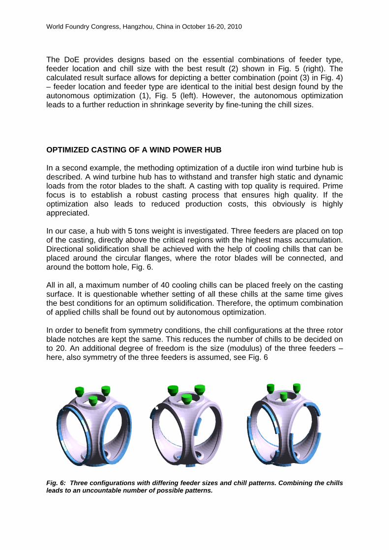
In a second example, the methoding optimization of a ductile iron wind turbine hub is described. A wind turbine hub has to withstand and transfer high static and dynamic loads from the rotor blades to the shaft. A casting with top quality is required. Prime focus is to establish a robust casting process that ensures high quality. If the optimization also leads to reduced production costs, this obviously is highly appreciated. In our case, a hub with 5 tons weight is investigated. Three feeders are placed on top of the casting, directly above the critical regions with the highest mass accumulation. Directional solidification shall be achieved with the help of cooling chills that can be placed around the circular flanges, where the rotor blades will be connected, and around the bottom hole, Fig. 6. All in all, a maximum number of 40 cooling chills can be placed freely on the casting surface. It is questionable whether setting of all these chills at the same time gives the best conditions for an optimum solidification. Therefore, the optimum combination of applied chills shall be found out by autonomous optimization. In order to benefit from symmetry conditions, the chill configurations at the three rotor blade notches are kept the same. This reduces the number of chills to be decided on to 20. An additional degree of freedom is the size (modulus) of the three feeders – here, also symmetry of the three feeders is assumed, see Fig. 6
Fig. 6: Three configurations with differing feeder sizes and chill patterns. Combining the chills leads to an uncountable number of possible patterns.
World Foundry Congress, Hangzhou, China in October 16-20, 2010
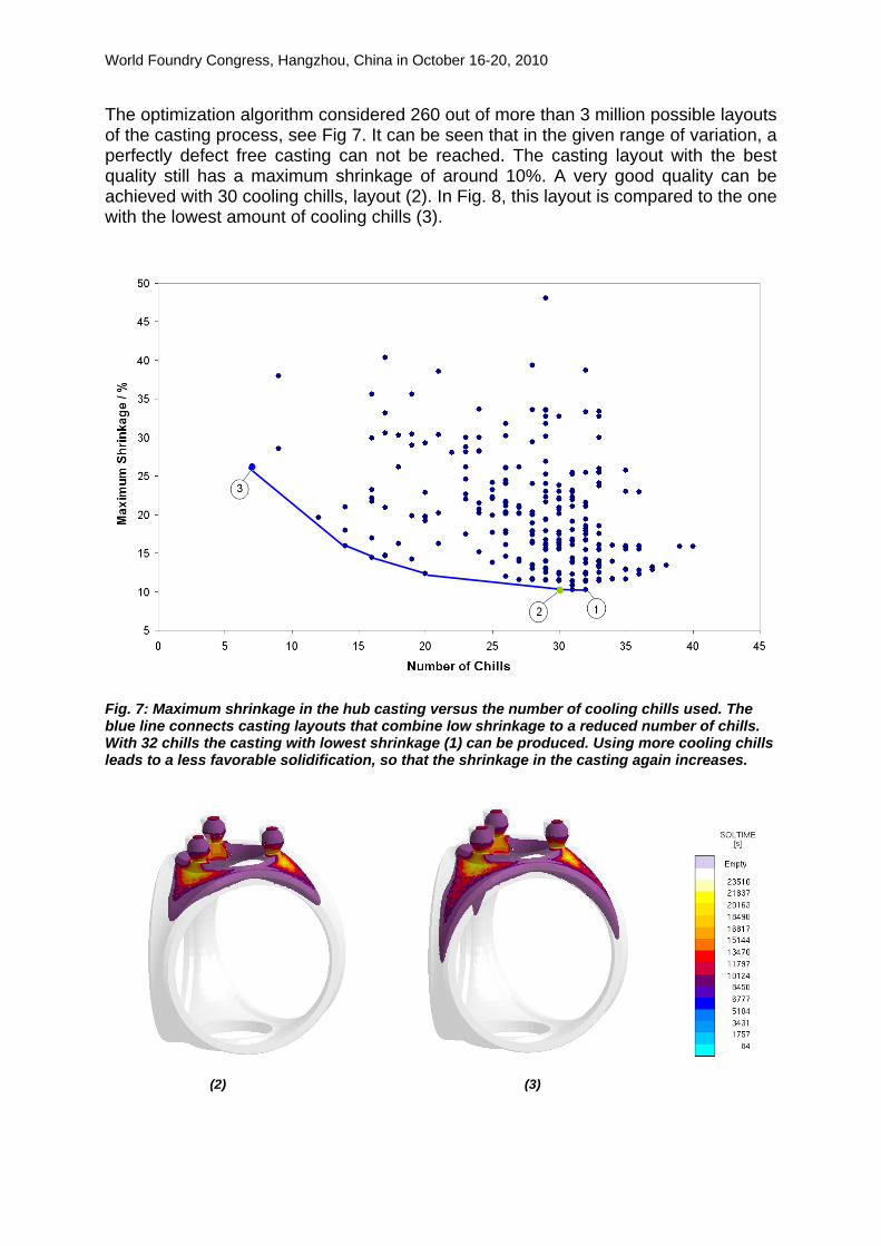
The optimization algorithm considered 260 out of more than 3 million possible layouts of the casting process, see Fig 7. It can be seen that in the given range of variation, a perfectly defect free casting can not be reached. The casting layout with the best quality still has a maximum shrinkage of around 10%. A very good quality can be achieved with 30 cooling chills, layout (2). In Fig. 8, this layout is compared to the one with the lowest amount of cooling chills (3).
Fig. 7: Maximum shrinkage in the hub casting versus the number of cooling chills used. The blue line connects casting layouts that combine low shrinkage to a reduced number of chills. With 32 chills the casting with lowest shrinkage (1) can be produced. Using more cooling chills leads to a less favorable solidification, so that the shrinkage in the casting again increases.
(2) (3)
World Foundry Congress, Hangzhou, China in October 16-20, 2010
Fig. 8: Distribution of solidification time (upper pictures) and of shrinkage (lower pictures) for the layouts (2) and (3). For the solidification time only values above 10.000 s are shown. For the layout (2), the last solidified regions are concentrated in the top part of the casting, close to feeders. In the layout (3) the final solidification is spread more towards the bottom of the casting. For the layout (2) shrinkage is much reduced in comparison to the layout (3).
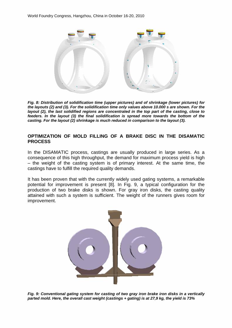
OPTIMIZATION OF MOLD FILLING OF A BRAKE DISC IN THE DISAMATIC PROCESS In the DISAMATIC process, castings are usually produced in large series. As a consequence of this high throughput, the demand for maximum process yield is high – the weight of the casting system is of primary interest. At the same time, the castings have to fulfill the required quality demands. It has been proven that with the currently widely used gating systems, a remarkable potential for improvement is present [8]. In Fig. 9, a typical configuration for the production of two brake disks is shown. For gray iron disks, the casting quality attained with such a system is sufficient. The weight of the runners gives room for improvement.
Fig. 9: Conventional gating system for casting of two gray iron brake iron disks in a vertically parted mold. Here, the overall cast weight (castings + gating) is at 27,9 kg, the yield is 73%
World Foundry Congress, Hangzhou, China in October 16-20, 2010
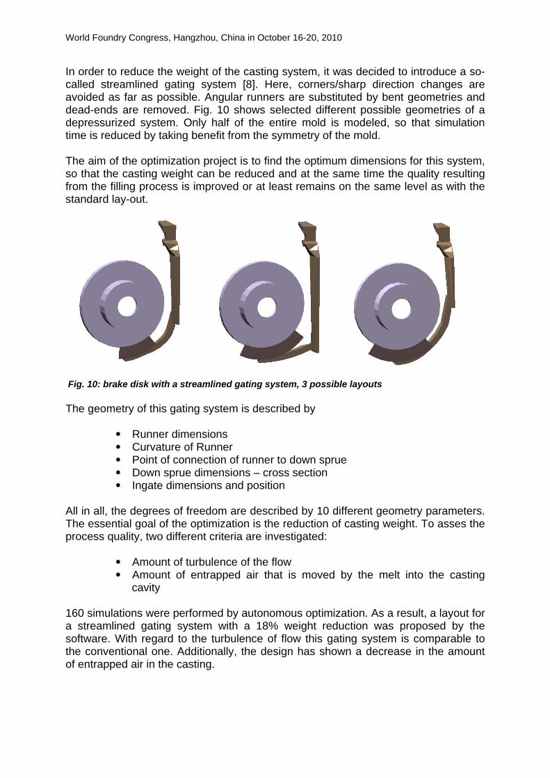
In order to reduce the weight of the casting system, it was decided to introduce a so-called streamlined gating system [8]. Here, corners/sharp direction changes are avoided as far as possible. Angular runners are substituted by bent geometries and dead-ends are removed. Fig. 10 shows selected different possible geometries of a depressurized system. Only half of the entire mold is modeled, so that simulation time is reduced by taking benefit from the symmetry of the mold. The aim of the optimization project is to find the optimum dimensions for this system, so that the casting weight can be reduced and at the same time the quality resulting from the filling process is improved or at least remains on the same level as with the standard lay-out.
Fig. 10: brake disk with a streamlined gating system, 3 possible layouts The geometry of this gating system is described by
• Runner dimensions • Curvature of Runner • Point of connection of runner to down sprue • Down sprue dimensions – cross section • Ingate dimensions and position
All in all, the degrees of freedom are described by 10 different geometry parameters. The essential goal of the optimization is the reduction of casting weight. To asses the process quality, two different criteria are investigated:
• Amount of turbulence of the flow • Amount of entrapped air that is moved by the melt into the casting
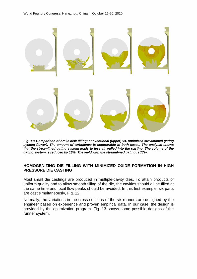
cavity 160 simulations were performed by autonomous optimization. As a result, a layout for a streamlined gating system with a 18% weight reduction was proposed by the software. With regard to the turbulence of flow this gating system is comparable to the conventional one. Additionally, the design has shown a decrease in the amount of entrapped air in the casting.
World Foundry Congress, Hangzhou, China in October 16-20, 2010
Fig. 11: Comparison of brake disk filling: conventional (upper) vs. optimized streamlined gating system (lower). The amount of turbulence is comparable in both cases. The analysis shows that the streamlined gating system leads to less air pulled into the casting. The volume of the gating system is reduced by 18%. The yield with the streamlined gating is 77%.
HOMOGENIZING DIE FILLING WITH MINIMIZED OXIDE FORMATION IN HIGH PRESSURE DIE CASTING Most small die castings are produced in multiple-cavity dies. To attain products of uniform quality and to allow smooth filling of the die, the cavities should all be filled at the same time and local flow peaks should be avoided. In this first example, six parts are cast simultaneously, Fig. 12. Normally, the variations in the cross sections of the six runners are designed by the engineer based on experience and proven empirical data. In our case, the design is provided by the optimization program. Fig. 13 shows some possible designs of the runner system.

World Foundry Congress, Hangzhou, China in October 16-20, 2010
Fig. 12: Casting lay-out for a high pressure die casting process with 6 cavities
Fig. 13: Three different variants of the runner system The filling time for each die cavity is calculated by the simulation. This is the time span from when the plunger begins to move until the complete filling of the cavity. The objective for the software is to reduce the deviations in filling times for the different die cavities as much as possible by selecting adequate runner cross sections. Apart from the homogeneous filling of all cavities, oxides in the castings should also be avoided in this example. As a result of the simulated die filling, the intensity with which the melt is exposed to air can also be analyzed as a local distribution across the filled die cavity. On this basis, a calculated reduction of oxide formation in the cavities was defined as the second target function of the optimization program.
World Foundry Congress, Hangzhou, China in October 16-20, 2010
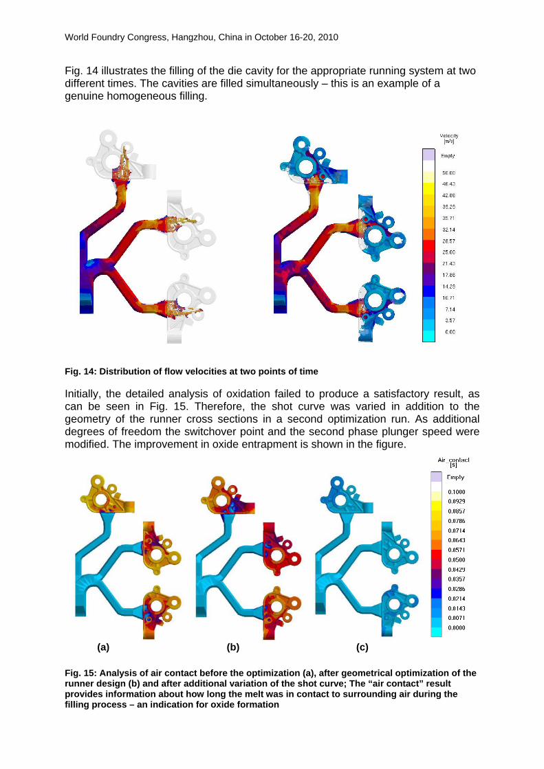
Fig. 14 illustrates the filling of the die cavity for the appropriate running system at two different times. The cavities are filled simultaneously – this is an example of a genuine homogeneous filling.
Fig. 14: Distribution of flow velocities at two points of time
Initially, the detailed analysis of oxidation failed to produce a satisfactory result, as can be seen in Fig. 15. Therefore, the shot curve was varied in addition to the geometry of the runner cross sections in a second optimization run. As additional degrees of freedom the switchover point and the second phase plunger speed were modified. The improvement in oxide entrapment is shown in the figure.
(a) (b) (c)
Fig. 15: Analysis of air contact before the optimization (a), after geometrical optimization of the runner design (b) and after additional variation of the shot curve; The “air contact” result provides information about how long the melt was in contact to surrounding air during the filling process – an indication for oxide formation

World Foundry Congress, Hangzhou, China in October 16-20, 2010
This result underlines the major impact the shot curve has on the quality of a casting and therefore also the necessity of considering this parameter in the optimization of the gating lay-out.
IMPROVED DEVELOPMENT OF CASTING OF AN ALUMINUM CRANKCASE WITH GREY IRON LINERS For Aluminum crankcases often grey iron liners are used. Main reason for this combination is the reduced weight of aluminum in combination to the improved wear resistance of iron parts in contact to the pistons. It is obvious that this close assembly of different materials results in high demands for a proper set-up of the casting process.
Fig. 16: Aluminum crankcase with grey iron liners. Before pouring the Aluminum, grey iron liners are pre-heated and placed inside the mold.
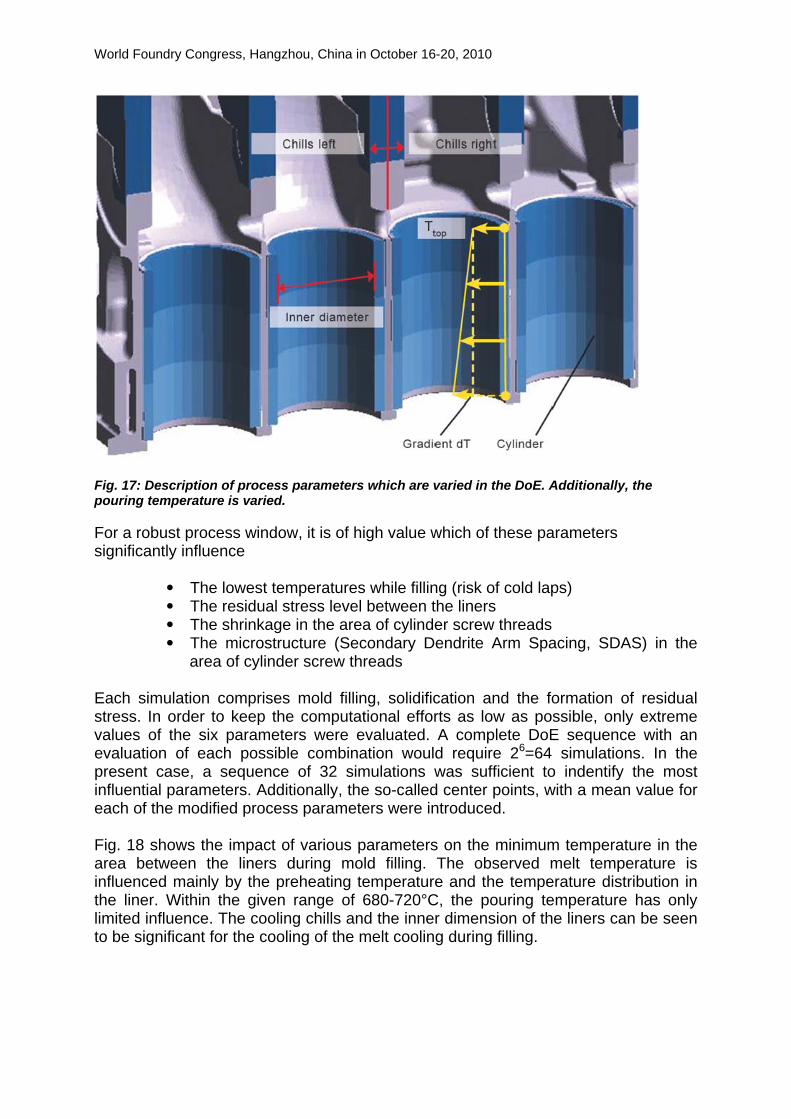
In order to achieve the required quality, a proper flow of liquid aluminum between the liners to avoid cold laps has to be guaranteed. Additionally the potential risk of increased residual stresses needs to be taken care of. Finally, special focus has to be given to those areas where the cylinder head is connected – there, threads will be machined later and therefore a high casting quality is required. Process parameters which have been considered for the evaluation are the pouring temperature, the preheating temperature profile of liners, the liner thickness as well as the dimensions of cooling chills, see Fig. 17. In total 6 process parameters are varied.
World Foundry Congress, Hangzhou, China in October 16-20, 2010
Fig. 17: Description of process parameters which are varied in the DoE. Additionally, the pouring temperature is varied. For a robust process window, it is of high value which of these parameters significantly influence
• The lowest temperatures while filling (risk of cold laps) • The residual stress level between the liners • The shrinkage in the area of cylinder screw threads • The microstructure (Secondary Dendrite Arm Spacing, SDAS) in the
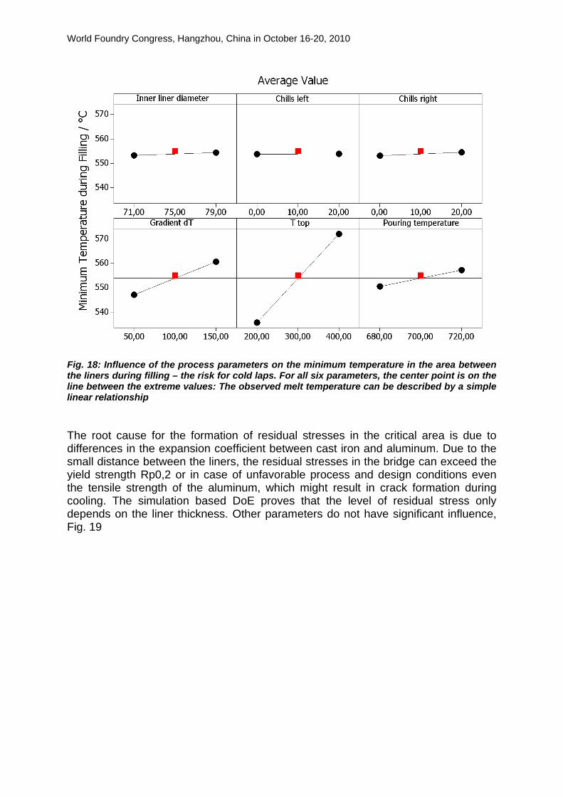
area of cylinder screw threads Each simulation comprises mold filling, solidification and the formation of residual stress. In order to keep the computational efforts as low as possible, only extreme values of the six parameters were evaluated. A complete DoE sequence with an evaluation of each possible combination would require 26=64 simulations. In the present case, a sequence of 32 simulations was sufficient to indentify the most influential parameters. Additionally, the so-called center points, with a mean value for each of the modified process parameters were introduced. Fig. 18 shows the impact of various parameters on the minimum temperature in the area between the liners during mold filling. The observed melt temperature is influenced mainly by the preheating temperature and the temperature distribution in the liner. Within the given range of 680-720°C, the pouring temperature has only limited influence. The cooling chills and the inner dimension of the liners can be seen to be significant for the cooling of the melt cooling during filling.
World Foundry Congress, Hangzhou, China in October 16-20, 2010
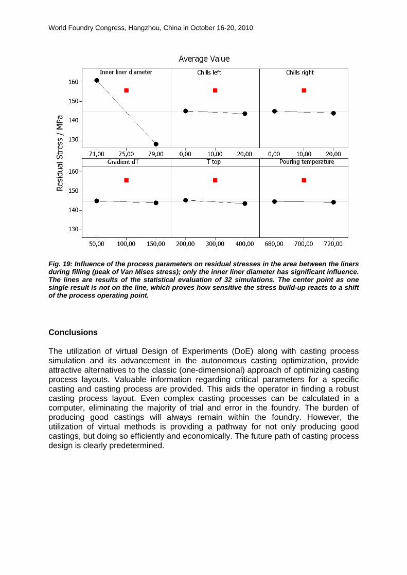
Fig. 18: Influence of the process parameters on the minimum temperature in the area between the liners during filling – the risk for cold laps. For all six parameters, the center point is on the line between the extreme values: The observed melt temperature can be described by a simple linear relationship The root cause for the formation of residual stresses in the critical area is due to differences in the expansion coefficient between cast iron and aluminum. Due to the small distance between the liners, the residual stresses in the bridge can exceed the yield strength Rp0,2 or in case of unfavorable process and design conditions even the tensile strength of the aluminum, which might result in crack formation during cooling. The simulation based DoE proves that the level of residual stress only depends on the liner thickness. Other parameters do not have significant influence, Fig. 19
World Foundry Congress, Hangzhou, China in October 16-20, 2010
Fig. 19: Influence of the process parameters on residual stresses in the area between the liners during filling (peak of Van Mises stress); only the inner liner diameter has significant influence. The lines are results of the statistical evaluation of 32 simulations. The center point as one single result is not on the line, which proves how sensitive the stress build-up reacts to a shift of the process operating point. Conclusions The utilization of virtual Design of Experiments (DoE) along with casting process simulation and its advancement in the autonomous casting optimization, provide attractive alternatives to the classic (one-dimensional) approach of optimizing casting process layouts. Valuable information regarding critical parameters for a specific casting and casting process are provided. This aids the operator in finding a robust casting process layout. Even complex casting processes can be calculated in a computer, eliminating the majority of trial and error in the foundry. The burden of producing good castings will always remain within the foundry. However, the utilization of virtual methods is providing a pathway for not only producing good castings, but doing so efficiently and economically. The future path of casting process design is clearly predetermined.

World Foundry Congress, Hangzhou, China in October 16-20, 2010
References [1] Montgomery, D. C.: Design and Analysis of Experiments, 4th Edition, John
Wiley and Sons, 1997 [2] Box, G.E.P, W.G. Hunter, and J.S. Hunter, Statistics for
Experimenters, John Wiley and Sons, 1978. [3] A. Egner-Walter, I. Hahn, W. Simon, Verkürzung des Entwicklungsprozesses
von Gussteilen durch Einsatz von virtueller DoE, 5. VDI-Tagung „Gießtechnik im Motorenbau“, Magdeburg, 10./11. Februar 2009
[4] I. Hahn, J.C. Sturm and C. Heisser, Design of Experiments and Casting Process Simulation, to be published in AFS Transactions, 2010
[5] G. Hartmann et al., Autonome rechnerische Speiseroptimierung für komplexe Modelle im Eisenguss; die zweite Generation der Gießsimulation, Giesserei 91 (2004), Nr.10, S. 22 – 30
[6] I. Hahn, G. Hartmann, Selbsttätige rechnerische Optimierung im Druckgießprozess, Giesserei 95 (2008), Nr. 9, S. 36-45
[7] J.C. Sturm, Optimierung von Gießtechnik und Gussteilen, Symposium „Simulation in der Produkt- und Prozessentwicklung“, 5.-7. November 2003, Bremen
[8] S. Skov-Hansen, N. Tiedje, Reduced energy consumption by using streamlined gating systems, China Foundry Association Congress – 8, 2008, Shanghai, China