autonomous operation of low voltage...
TRANSCRIPT

156
Autonomous Operation of Low Voltage Microgrids
AuthorsIrena WasiakRyszard PawełekPaweł Kelm
Keywordsmicrogrids, microgrid autonomous operation, microgrids control, energy storage
AbstractThe article describes the possibilities of LV microgrids operation in the island mode. Control strategies of energy sources connected to the grid by means of invertors are discussed, either for a microgrid connected to the supplying network or during the island mode operation. The presented results of research were conducted at the Laboratory of Distributed Generation at Lodz University of Technology. The study was performed for two variants of reference voltage source: the battery storage and microturbine respectively.
DOI: 10.12736/issn.2300-3022.2014413
1. IntroductionIncreased penetration of distributed sources leads to the power system’s decentralization and changes in the distribution grids’ nature from passive to active. An active grid, which facilitates processes of electricity generation, transmission, as well as distri-bution and use, constitutes a power microgrid. The microgrid integrates distributed energy sources, including renewable sources (RES), controllable and uncontrollable loads, and energy storages. A microgrid’s topology and characteristics depends on its intended use. There are microgrids owned by the operator and being part of the distribution grid, as well as microgrids that supply industrial and municipal customers [1]. Compared with traditional receiving grids, the microgrid architecture provides new operating opportunities including electricity supply and demand control in a way that ensures technical and economic benefits to the owner.Connecting electricity sources to a distribution grid is associ-ated with phenomena that may affect the reliability of supply and quality of electricity supplied to customers. To a large extent these phenomena arise from the specifics of sources utilising renewable energy, such as wind or solar power plants, charac-terized by their generation output variability depending on the primary energy availability and variability. For every grid the allowable power of sources can be determined, the connection of which will neither worsen the grid’s operating conditions nor result in excesses of its characteristic parameters. This power is a measure of the grid’s ability to integrate sources, so called hosting capacity [2].To ensure a power grid’s proper operating conditions, taking into account the interactions, but also the opportunities brought about by its integration with sources, installation of “smart” systems is required for measurement and data acquisition, and
provision of an appropriate communication infrastructure [3]. This is an extremely important element of the microgrid archi-tecture, allowing monitoring and managing the system opera-tion in real time.In most cases microgrids operate connected with the supplying network. Currently applicable regulations, both in Poland and in other countries, require disconnection of a source in the event of its lost connection to the network [4, 5]. This is mainly due to the technical problems associated with uncontrolled autonomous operation, and above all, the risk of personnel safety hazards and possible damage to equipment in the event of its asynchronous re-connection with the network [3, 6]. On the other hand, with increasing penetration of distributed generation, sources’ auto-shutdown during disruptions in the supplying network signifi-cantly reduces the reliability of consumers’ supply by electricity companies. The ability to maintain supply from local sources is an advantageous feature of a grid with distributed generation – unused in this case – even if the island operation delivers elec-tricity with less power and lower quality. For industrial consumers this could mean a significant reduction in economic losses caused by potential interruptions of their electricity supply.Intended island operation of microgrids has recently become a subject of lively discussion between electricity companies and consumers. Many publications report benefits of maintaining consumers’ supply despite lost connection to the supplying network , technical possibilities of controlled island opera-tion, and the need to revise the relevant applicable regulations [1, 6, 7, 8].According to the authors, a microgrid connected to the supplying network and normally operating in connection with it should be capable of autonomous operation in the event of fault in the network resulting in an lost of the supply or lowering the
I. Wasiak et al. | Acta Energetica 4/21 (2014) | 156–163

157
voltage below the immunity curve defined for this microgrid. This paper is devoted to a discussion of the autonomous opera-tion conditions, and the control strategy applicable in such a case. The discussion is illustrated with results of studies carried out in a real low voltage microgrid configured in the Laboratory of Distributed Generation of Lodz University of Technology.
2. Microgrid operation control strategyMicrogrids utilise a variety of sources, which, depending on the type of primary energy conversion, are connected to the network through induction generators, synchronous generators, or power converters. The source connection through a voltage source converter (VSC) is one of the most common solutions for controllable sources, as well as uncontrollable sources of renew-able solar and wind energy. In such a case the source opera-tion control strategy boils down to appropriate control of the converters, and depends on the source type and microgrid oper-ating mode.
2.1. Microgrid grid connected operationIn a microgrid connected to the supplying network no direct voltage and frequency control is required. In this case the source converters are usually operated as current controlled voltage source converters (CC-VSC), in synchronization with the supply voltage, according to P-Q strategy aiming to obtain the appro-priate active and reactive powers.Current control may be implemented in various controller types and based on various algorithms. One of the most common options involves rotation components dq0 (Fig. 1).In the circuit shown in Fig. 1 the converter’s reference phase voltage is determined on the basis of mutually orthogonal current components idref and iqref.The references determination algorithm depends on the source type. RES sources usually operate with the maximum active power output available under the circumstances, at the tgj = 0. To determine idref component of the reference current, a Udc voltage controller in the intermediate circuit is used. The local control system uses the MPPT (maximum point of power tracking) algorithm. The sources’ active power output is changed at random, depending on the primary energy variations. Since this type of control is independent from other sources and loads, it is referred to as a non-interactive control [3].
Controllable sources are subject to interactive control. The idref component of reference current is determined by comparison of the active power setpoint and measurement, and iqref compo-nent by comparison of respective reactive powers. The idref component can also be determined from voltage change Udc in the source’s intermediate circuit. To generate the inverter’s firing pulses the PWM technique is used, whereby voltage phase angle Θ is determined in the PLL loop. An important feature of source control in CC-VSC mode is natural limitation of the inverter current under disturbances [3, 9].Reference powers can be set by the operator or determined by the master control system (central controller) so as to mini-mize costs incurred by the microgrid owner, while appropriate technical conditions of the system operation are ensured [10]. Mathematically, the problem boils down to multi-criteria opti-misation under selected constraints. Relevant literature reports various forms of the objective function, depending on the microgrid architecture. In most cases they refer to the minimum generation costs in controllable sources, taking into account the fuel, as well as start-up and operating, costs [11, 12, 13, 14, 15]. The constraints considered in the optimisation process may concern generation parameters (e.g. maximum output power, start-up time), grid parameters (allowable line current-carrying capacity), and electricity quality parameters (voltage deviation in grid nodes) [16]. In this way, such microgrid control is enabled that prevents technical parameters’ excesses, even when the sources’ output exceeds the grid’s capacity to integrate them. Storages installed in the microgrid can support the uncontrollable sources’ operation [17, 18, 19] or contribute to power balancing after various criteria, so called load levelling, peak shaving [20, 21]. To include storage in the optimisation process, the objective func-tion has to be formulated as the minimum energy cost over the concerned time interval [16, 22, 23].
2.2. Autonomous microgrid operation The objective of the control strategy implemented in the source’s stand-alone operation is to ensure power balance and to main-tain the preset voltage and frequency in the connection point (U-f strategy) [6, 24]. This requires the control mode known as voltage controlled voltage source inverter (VC-VSC), (Fig. 2) and the source’s reserve power sufficient to cover the power demand changes. The U-f strategy does not ensure internal short circuit current limitation [24].
Fig. 1. Block diagram of P-Q strategy based source control Fig. 2. Block diagram of U-f strategy based source control
I. Wasiak et al. | Acta Energetica 4/21 (2014) | 156–163

158
In a microgrid to which several sources are connected, only one of these can be the reference voltage source. In such a situation, the reference source follows the U-f strategy, while the other sources implement the P-Q strategy. Load changes are covered in a natural way by the reference source, whereas a change in the other sources’ output requires an external signal, e.g. from the central controller [25, 26]. A microgrid’s transition, following its disconnection from the supplying network, to autonomous operation usually requires switching the reference source control mode (from P-Q to U-f). Also known are hierarchical or hybrid control strategies that combine CC-VSC and VC-VSC modes and are common to sources connected to supplying grids and oper-ated in an island mode [9, 27]. The control mode is changed auto-matically and does not require switching in the control system.Study [28] presents the control of a microturbine as a source of active and reactive power or the reference voltage source. The control system uses two loops: the inner loop is dedicated to current control in a dq coordinate system, and the outer loop is used to control DC voltage in the intermediate circuit. The signal at the output of the outer control loop’s PI controller is the reference signal for id active current component. The refer-ence value of iq current depends on the source’s required reactive power output. Typically for Q = 0 also iq = 0. The inverter voltage’s synchronization with the supplying grid voltage is provided by a PLL loop. In its autonomous operation the microturbine main-tains a constant output voltage (U-f control mode). The frequency and rms voltage are controlled. The PI controller of DC voltage reduces the main voltage controller’s reference value in order to avoid the inverter’s saturation. The output voltage frequency is controlled by the virtual PLL block.It should be noted that while reactive power of sources operated in connection with the suppling network may be equal to zero, then in their island operation reactive power control is necessary to obtain active power balance at appropriate voltage param-eters. When sources in autonomous mode cannot generate the entire power demanded by loads, the demand must be reduced by shutting down some of the loads. This process, known as load shedding, is implemented in accordance with the adopted strategy of transition to controlled island operation and shut down priorities [6].Also, an energy storage system can be the reference voltage source. It play an important role in solving technical prob-lems of sources’ integration with the supplying network [20], and their technological development is conducive to practical applications. Two or more sources can actively participate in the microgrid voltage and frequency control [30, 31]. In such a case a control strategy should be implemented that involves appropriate load sharing between the sources. Load distribu-tion control in a system with several sources is a separate issue recently addressed in numerous publications, such as [29, 32, 33, 34, 35]. This issue will be undertaken by the authors in subse-quent studies.
3. The test microgridAt the Laboratory of Distributed Generation of Lodz University of Technology [36] a low voltage microgrid was configured in
the typical radial setup, connected to which were photovol-taic panels with rated capacity of 6 kWp, a Capostone C30 gas microturbine with rated capacity of 30 kW, a battery energy storage with rated capacity of 10 kW, and linear loads R, L, with power adjustable by a control autotransformer over the range of 0–30 kW (Fig. 3). The photovoltaic panels, as uncontrollable sources, operate continuously with the maximum output avail-able under given conditions. The energy storage is connected to the grid through Sunny Island 4500 inverters. Both the micro-turbine and the storage are provided with factory implemented control systems, allowing their operation under current and voltage control alike.The microturbine is usually current controlled when operated in grid connected mode. The turbine can be operated with an output setpoint of 0–30 kW, and the output is remotely adjusted by the factory application Capstone Remote Monitoring System, or by a control panel on the turbine. Depending on needs, a daily and weekly operation schedule can be programmed, or the output can be controlled in real time according to a schedule set by an external control system.
A loss of voltage causes the turbine’s emergency shutdown. Its restarting and adopted operation mode depend on the Power Connect settings:• Grid Connect – turbine resumes operation grid connected as
a current source• Stand Alone – turbine is restarted to autonomous operation
as the reference voltage source • Dual Mode – turbine operates in either Grid Connect or Stand
Alone mode depending on the grid configuration and the reference voltage presence/absence.
Fig. 3. Diagram of the test microgrid
I. Wasiak et al. | Acta Energetica 4/21 (2014) | 156–163

159
The grid connected storage operates in RUN_I mode of inverter i and, like the microturbine, it synchronizes with the grid voltage and frequency. The storage’s power intake depends on the battery type and the state of charge. At power outage, the storage can act as a UPS (current limited to 70 A, and maximum UPS duration 5 s), or immediately switch to island operation mode RUN_U as the reference voltage and power source. None of the devices is able to operate under voltage control in the presence of voltage in the to which it is connected. As follows from the foregoing description, the microgrid can operate autonomously in either of the following variants:• the storage is the reference voltage source (RUN_U), and the
microturbine operates in the grid connected mode, or• the microturbine operates as a volltage source, i.e. in stand
alone mode, and the storage operates in RUN_I mode.The both variants of the test microgrid operation were tested. To assess control capabilities of the devices that can be reference voltage sources, their static characteristics were first measured.
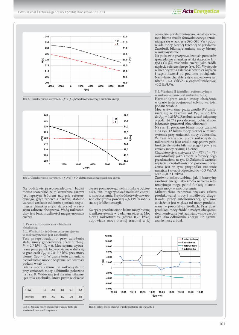
4. Static characteristics of energy sourcesThe gas microturbine and electrochemical energy storage system were tested, loaded consecutively with a resis-tance and an inductive reactance over the range corre-sponding to the sources’ rated capacity. As regards the storage, additional measurements were taken while it was charged from the micro-turbine as the power source. Fig. 4 and 5 show pairs of the gas microturbine’s static characteristics, respectively, U = f(P) and f = f(P), as well as U = f(Q) and f = f(Q). The presented results indicate that the microturbine maintains practically constant frequency throughout the load range, active power and reactive power alike. The frequency characteristics’ slopes are –0.001 Hz/kW i –0.001 Hz/kvar. The micro-turbine voltage changes by –0.13 V/kW and –0.32 V/kvar.Analogous pairs of characteristics determined for the energy storage are shown in Fig. 6-7. As is apparent from the measure-ments, the change in the storage frequency is –0.1 Hz/kW and –0.01 Hz/kvar. The slope of the storage’s voltage characteris-tics depends on its operating mode (charging/discharging),
and at charging is –0.56 V/kW, and at discharging –1.27 V/kW. The storage’s voltage characteristics as a function of reactive power is nonlinear highly variable.On the basis of the study it can be concluded that the gas microturbine is a better source of the reference voltage, as it
Fig. 4. Static characteristics U = f(P) and f = f(P) of the microturbine
Fig. 5. Static characteristics U = f(Q) and f = f(Q) of the microturbine
Fig. 6. Static characteristics U = f(P) and f = f(P) of the electrochemical energy storage
Fig. 7. Static characteristics U = f(Q) and f = f(Q) of the electrochemical energy storage
I. Wasiak et al. | Acta Energetica 4/21 (2014) | 156–163

160
provides more stable power supply conditions (its static charac-teristics are stiffer) over a wider load range. The microturbine’s disadvantage is that it cannot store energy.
5. Stand-alone operation – object research
5.1. Option I (storage as the reference source in a microgrid)The test was performed assuming a constant power output of
the microturbine: Pt = 2,7 kW and Qt = 0. The photovoltaic panels’ active power output ranged PPV = 2,8–3,7 kW, at reactive power QPV = 0. The loads were changed five times during the test, and are specified in Tab. 1. Active power balance in the microgrid at the load changes is shown in Fig. 8. It evidences the balancing role of the energy
storage system, which for most of the measurement period served as a receiver, i.e. it stored surplus energy in the microgrid. At a transitory load increase above 6.6 kW, the storage had become an energy source.Fig. 9 shows reactive power balance in the microgrid in the considered period. The microturbine reactive power (0.25 kvar) corresponds to the reactive power lost in its connection circuit. Similarly, the photovoltaic source reactive power (changing in the range of 390–580 var) corresponds to the reactive power lost in the PV connection circuit. The storage compensates the changes of the reactive power in the microgrid.On the basis of the measurements, static characteristics U = f(S) and f = f(S) of the energy storage as the reference voltage
source were depicted (Fig. 10). They illustrate the clear depen-dence of the voltage and frequency on the load level. Slopes of the voltage and frequency characteristics are –7.2 V/kVA and –0.2 Hz/kVA, respectively.
5.2. Option II (microturbine as the reference source in a microgrid)Loads were consequently changed during the test according to the schedule in Tab. 2.The PV source output power changed from PPV = 2,6 kW to PPV = 0,25 kW. The storage was switched on at 14:37 and was retrieving charging power (operated as a receiver).Fig. 11 and 12 show, respectively, the active and reactive power balances in the microgrid at load changes. In this microgrid oper-ation option the microturbine, as a voltage source, acts as the balancing element and compensates active and reactive power changes.
Tab. 1. Load changes in the test for option I of the microgrid operation
Tab. 2. Load changes in the test for option I of the microgrid operation
Fig. 8. Active power balance in the microgrid, option I
Fig. 9. Reactive power balance in the microgrid, option I
-8 000
-6 000
-4 000
-2 000
0
2 000
4 000
6 000
8 000
10 000
12 000
13:00 13:05 13:10 13:15 13:20 13:25 13:30 13:35 13:40 13:45t [hh:mm]
P [W
]
P microturbineP storageP photovoltaicsP load
-8 000
-6 000
-4 000
-2 000
0
2 000
4 000
6 000
8 000
10 000
12 000
13:00 13:05 13:10 13:15 13:20 13:25 13:30 13:35 13:40 13:45t [hh:mm]
Q [v
ar]
Q microturbineQ storageQ photovoltaicsQ load
P [kW] 1.3 2.8 4.8 6.1 4.2
Q [kvar] 0.9 2.6 4.6 5.9 4.0
P [kW] 5.9 9.5 13.6 4.2
Q [kvar] 5.3 8.1 11.5 3.9
Fig. 10. Static characteristics of the energy storage, microgrid operation option I
I. Wasiak et al. | Acta Energetica 4/21 (2014) | 156–163

161
Static characteristics U = f(S) i f = f(S) of the microturbine as the reference source are shown in Fig. 13. The dependence of the voltage and frequency on the load is much lower in this case and amounts to –0.3 V/kVA and –0.002 Hz/kVA.Both the microturbine and battery energy storage, as the refer-ence voltage sources, can balance power in the microgrid.
The microturbine provides a greater range of output power, and the possibility of long-term autonomous operation, when the load exceeds the other sources’ output. When the sources’ output is high, and the load is low, a storage system needs to be installed as an energy receiver, or the sources’ output has to be reduced.
6. Final conclusionsLow-voltage power microgrids with distributed energy sources offer new opportunities and can help to increase the reliability of electricity supply to customers.A microgrid can maintain the supply to customers while they are disconnected from the commercial power network, provided there is an adequate capacity of its sources and an appropriate control strategy.The studies conducted on the test microgrid at the Laboratory of Distributed Generation, Institute of Electrical Power Engineering of Lodz University of Technology allowed determining the prop-erties of a gas microturbine and battery energy storage as poten-tial reference voltage sources during the microgrid’s short-term standalone operation. The study results are the basis for further research aiming to determine a method for selecting a microgrid architecture and control strategy taking into account interaction of energy storage and controllable sources.
REFERENCES
1. Driesen J., Katiraei F., Design for Distributed Energy Resources, IEEE Power & Energy Magazine 2008, No. 8.
2. Bollen M.H-J., Yang Y., Hassan F., Integration of Distributed Generation in the Power System – A Power Quality Approach, Proc. 13th International Conference on Harmonics and Quality of Power, Wollongong, Australia 28.09-1.10 2008.
3. Katiraei F. et al., Microgrid Management. Controls and Operation Aspects of Microgrids, IEEE Power & Energy Magazine, May/June 2008.
4. IEEE Standard 1547: Standard for Interconnecting Distributed Resources with Electric Power Systems.
5. IRiESD, Instrukcja Ruchu i Eksploatacji Sieci Dystrybucyjnych [IRiESD Distribution Grid Code], PGE Łódź – Teren, 2009.
6. Balaguer I.J. et al., Intelligent Control for Intentional Islanding Operation of Microgrids, ISCET 2008.
7. Gomez J.C., Morcos M.M., Distributed Generation: Exploitation of Islanding Operation Advantages, IEEE/PES Transmission and Distribution Conference and Exposition: Latin America, 2008.
8. Piargi P., Lasseter R.H., Autonomous Control of Microgrids, IEEE PES General Meeting, 2006.
9. Gao F., Iravani M.R., A Control Strategy for a Distributed Generation Unit in Grid Connected and Autonomous Modes of Operation, IEEE Trans. on Power Delivery April 2008, Vol. 23, No. 2.
10. Colson C.M., Nehir M.H., A Review of Challenges to Real-Time power Management of Microgrids, IEEE Power & Energy Society General Meeting, 2009.
11. Alvarez E. et al., On-line Minimization of Running Costs, Greenhouse Gas Emission and the Impact of Distributed Generation using Microgrids on the Electrical System, IEEE PES/IAS Conference on Sustainable Alternative Energy, 28–30.09.2009.
Fig. 11. Active power balance in the microgrid, option II
Fig. 12. Reactive power balance in the microgrid, option II
Fig. 13. Static characteristics of the microturbine, microgrid operation option II
-25 000
-20 000
-15 000
-10 000
-5 000
0
5 000
10 000
15 000
20 000
25 000
14:20 14:25 14:30 14:35 14:40 14:45 14:50 14:55t [hh:mm]
P [W
]
P microturbineP storageP photovoltaicsP load
-15 000
-10 000
-5 000
0
5 000
10 000
15 000
14:20 14:25 14:30 14:35 14:40 14:45 14:50 14:55t [hh:mm]
Q [v
ar]
Q microturbineQ storageQ photovoltaicsQ load
I. Wasiak et al. | Acta Energetica 4/21 (2014) | 156–163

162
12. Gu W., Wu Z., Yuan X., Microgrid Economic Optimal Operation of the Combined Heat and Power System with Renewable Energy, IEEE Power Energy Soc. Gen. Meet., 25–29 July 2010.
13. Hernandez-Aramburo C.A., Green T.C., Fuel Consumption Minimisation of a Micro-grid, Industry Application Conference, 39th IAS Annual Meeting, 3–7.10.2004.
14. Mohamed F.A., Koivo H.N., On-line Management of MicroGrid with Battery Storage Using Multiobjective Optimisation, International Conference on Power Engineering, Energy and Electrical Drive POWERENG 2007, 12–14.04.2007.
15. Vahedi H., Noroozian R., Hosseini S.H., Optimal Management of MicroGrid Using a Differential Evolution Approach, 7th International Conference on the European Energy Market (EEM), 23–25 June 2010.
16. Gburczyk P. et al., Management System as a Means for the Integration of Distributed Energy Sources with Low Voltage Network, IEEE International Conference on Electrical Power Quality and Utilisation (EPQU ’2011), Lisbon (Portugal), 17–19 October 2011, pp. 1–5.
17. Barote L., Georgescu M., Marinescu C., Smart Storage Solution for Wind Systems, IEEE Power Tech Conference, Bucharest, Romania, 28.06–2.07 2009.
18. Faias S. et al., Evaluation of Energy Storage Devices for Renewable Energies Integration, Application to a Portuguese Wind Farm, 5th Int. Conference on European Electricity Market (EEM 2008), Lisbon, Portugal, 2008.
19. Qian K. et al., Benefts of Energy Storage in Power Systems with High Level of Intermittent Generation, 20th Int. Conference on Electricity Distribution (CIRED2009), Praque, 8–11.06.2009.
20. Wasiak I., Pawełek R., Mieński R., Zasobniki energii w mikrosystem-ach elektroenergetycznych [Energy storage in power systems], conference “Current Problems in Power Engineering”, Jurata, 8–10 June 2011, pp. 159–166.
21. Zamora R., Srivastava A.K., Controls for Microgrids with Storage: Review, Challenges, and Research Needs, Renewable and Sustainable Energy Reviews 2010, No. 14, pp. 2009–2018.
22. Chakraborty S., Simoes M.G., PV-Microgrid Operational Cost Minimization by Neural Forecasting and Heuristic Optimisation, Industry Applications Society Annual Meeting, IAS ’08 IEEE, 2008.
23. Guan X., Xu Z., Jia Q.-S., Energy-efficient Buildings Facilitated by Microgrid, IEEE Trans. on Smart Grid 2011, Vol. 2, No. 1.
24. Gao F., Iravani M.R., A Control Strategy for a Distributed Generation Unit in Grid Connected and Autonomous Modes of Operation, IEEE Trans. On Power Delivery, Vol. 23, No. 2, April 2008.
25. Chowdhury S.P. et al., Operation and control of DG based power island in Smart Grid environment, 20th Int. Conference and Exhibition on Electricity Distribution, CIRED 2009.
26. Ghadimi A.A., Razavi F., Ghafarpour R., Control of Islanded Inverter Interfaced Distributed Generation Units For Power Quality Improvement, 14th Int. Conference on Harmonics and Quality of Power, ICHQP 2010.
27. Delghavi M.B., Yazdani A., A Unified Control Strategy for Electronically Interfaced Distributed Energy Resources, IEEE Trans. on Power Delivery 2012, Vol. 27, No. 2.
28. Gaonkar D.N., Patel R.N., Pillai G.N., Dynamic Model of Microturbine Generation System for Grid Connected/islanding operation, IEEE Int. Conference on Industrial Technology, ICIT 2006.
29. Sao C.K., Lehn P.W., Control and Power Management of Converter Fed Microgrids, IEEE Trans. on Power Systems August 2008, Vol. 23, No. 3.
30. Katiraei F., Iravani R., Power Management Strategies for a Microgrid with Multiple Distributed Generation Units, IEEE Transaction on Power Systems 2006, Vol. 21, No. 4.
31. Pecas Lopes J.A., Moreira C.L., Madureira A.G., Defning Control Strategies for Microgrids Islanded Operation, IEEE Transaction on Power System May 2006, Vol. 21, No. 2.
32. Brabandere K. et al., A Voltage and Frequency Droop Control Method for Parallel Inverters, IEEE Transaction on Power Electronics July 2007, Vol. 22, No. 4.
33. Majumder R. et al., Load Sharing and Power Quality Enhanced Operation of a Distributed Microgrid, IET Renewable Power Generation 2009, Vol. 3, Iss. 2.
34. Majumder R. et al., Droop Control of Converter-Interfaced Microsources in Rural Distributed Generation, IEEE Trans. on Power Delivery October 2010, Vol. 25, No. 4.
35. Vandoorn T. et al., A Control Strategy for Islanded Microgrids with DC-link Voltage Control, IEEE Trans. on Power Delivery April 2011, Vol. 26, No. 2.
36. Pawełek R. et al., Mikrosystem – węzeł energetyczny w Instytucie Elektroenergetyki Politechniki Łódzkiej, [Microgrid – a power node at Institute of Electrical Power Engineering of Łódź University of Technology] conference “Current Problems in Power Engineering”, Jurata, 8–10 June 2011, pp. 143–150.
I. Wasiak et al. | Acta Energetica 4/21 (2014) | 156–163

163
Irena WasiakLodz University of Technology
e-mail: [email protected]
Graduated from Lodz University of Technology. Throughout her professional career so far a researcher/lecturer at the Institute of Electrical Power Engineering of the
university (LUT). She has gained the doctor and habilitated doctor degrees in power engineering. In 2002–2008 she was Deputy Dean of the Faculty of Electrical
Engineering, Electronics, Computer Science and Automatics of the university. Currently she is the Head of the Institute of Electrical Power Engineering. A member of
IET (The Institution of Engineering and Technology) the Committee for Electricity Quality and Effective Utilisation of Association of Polish Electrical Engineers (SEP) and
an associate member of the Power System Section of PAN Polish Academy of Sciences. The deputy editor-in-chief of Electrical Power Quality and Utilisation journal
and the co-chairman of an international conference under the same name. The area of her research activities includes power quality, integration of distributed energy
sources in power grids, and power microgrid operation.
Ryszard PawełekLodz University of Technology
e-mail: [email protected]
A graduate of the Faculty of Electrical Engineering of the Lodz University of Technology (1977). Currently an assistant professor at the Institute of Electrical Power
Engineering of his alma mater, and the Institute’s Deputy Director. The area of his research interest includes power quality, distributed generation, and power micro-
grids. A chair of The Polish Committee for Electricity Quality and Effective Utilisation of Association of Polish Electrical Engineers (SEP), and the Committee’s Vice-
President for Science. A SEP Association of Polish Electrical Engineers expert in electricity quality.
Paweł KelmLodz University of Technology
e-mail: [email protected]
A graduate of the Faculty of Electrical Engineering, Electronics, Computer Science and Automatics of Lodz University of Technology (2004). He gained his PhD at his
alma mater (2012).
A former researcher/lecturer at the University of Strathclyde in Glasgow (2007-2008). Currently an assistant professor at the Institute of Electrical Power Engineering of
Lodz University of Technology. The area of his research interest: electricity quality, distributed generation, microgrids, and lighting technology.
I. Wasiak et al. | Acta Energetica 4/21 (2014) | 156–163

164
Praca autonomiczna mikrosystemów elektroenergetycznych niskiego napięcia
AutorzyIrena WasiakRyszard PawełekPaweł Kelm
Słowa kluczowemikrosystemy elektroenergetyczne, praca wyspowa, sterowanie pracą mikrosystemów, zasobniki energii
StreszczenieW artykule autorzy przedstawili możliwości pracy autonomicznej mikrosystemów niskiego napięcia. Omówiono strategie sterowania źródłami energii, przyłączonymi do sieci za pomocą przekształtników, podczas pracy w połączeniu z siecią zasi-lającą oraz podczas pracy wyspowej. Zaprezentowano wyniki badań przeprowadzonych w mikrosystemie skonfigurowanym w Laboratorium Generacji Rozproszonej Instytutu Elektroenergetyki Politechniki Łódzkiej. Badania wykonano w dwóch wariantach: w pierwszym źródłem napięcia referencyjnego była mikroturbina, w drugim elektrochemiczny zasobnik energii.
1. WprowadzenieWzrost penetracji źródeł rozproszonych prowadzi do decentralizacji systemu elektro-energetycznego i zmiany charakteru dystry-bucyjnych sieci odbiorczych z sieci pasyw-nych na aktywne. Sieć aktywna, w której realizowane są procesy generacji, przesyłu i rozdziału oraz użytkowania energii, tworzy mikrosystem elektroenergetyczny. Mikrosystem integruje rozproszone źródła energii, w tym energii odnawialnych, sterowalne i niesterowalne odbiory oraz zasobniki energii. Topologia i charaktery-styka mikrosystemu zależy od jego prze-znaczenia. Wyróżnić można mikrosystemy należące do operatora i stanowiące frag-ment sieci dystrybucyjnej, a także mikrosys-temy zasilające odbiorców przemysłowych i komunalno-bytowych [1]. W porównaniu z tradycyjnymi sieciami odbiorczymi, archi-tektura mikrosystemów zapewnia nowe możliwości funkcjonowania, obejmujące zarówno sterowanie wytwarzaniem, jak i zapotrzebowaniem na energię elektryczną w sposób zapewniający właścicielowi korzyści techniczne i ekonomiczne.Przyłączanie źródeł energii do sieci dystry-bucyjnych wiąże się z występowaniem zjawisk, które mogą wpłynąć na niezawod-ność zasilania i jakość energii elektrycznej dostarczanej do odbiorców. W dużej mierze zjawiska te wynikają ze specyfiki źródeł wykorzystujących energie odna-wialne, takich jak elektrownie wiatrowe lub słoneczne, charakteryzujących się zmien-nością mocy wytwarzanej w zależności od dostępności i zmienności energii pier-wotnej. Dla każdej sieci można wyznaczyć dopuszczalną moc źródeł, których przy-łączenie nie pogorszy warunków pracy tej sieci i przekroczenia wartości charaktery-zujących ją parametrów. Moc ta jest miarą zdolności sieci do integracji źródeł (tzw. hosting capacity [2]).Zapewnienie właściwej pracy sieci elek-troenergetycznej, przy uwzględnieniu wzajemnych oddziaływań, ale też możli-wości, jakie niesie ze sobą integracja źródeł i sieci, wymaga zainstalowania inteligent-nych układów do pomiaru i akwizycji danych oraz stworzenia odpowiedniej
infrastruktury komunikacyjnej [3]. Jest to niezwykle ważny element architektury mikrosystemu, pozwalający na moni-torowanie i zarządzanie pracą układu w czasie rzeczywistym. W większości przypadków mikrosys-temy pracują w połączeniu z siecią zasi-lającą. Obowiązujące aktualnie prze-pisy zarówno w Polsce, jak i w innych krajach wymagają wyłączenia źródła w przypadku utraty połączenia z siecią [4, 5]. Wynika to głównie z problemów technicznych, jakie wiążą się z niekontrolo-waną pracą wyspową, a przede wszystkim z ryzyka wystąpienia zagrożenia bezpie-czeństwa personelu i możliwości uszko-dzenia urządzeń w przypadku niesyn-chronicznego ponownego połączenia z siecią [3, 6]. Z drugiej jednak strony, przy wzroście penetracji generacji rozpro-szonej, automatyczne wyłączenia źródeł w trakcie zakłóceń w sieci zasilającej znacząco, obniżają niezawodność zasilania odbiorców przez przedsiębiorstwo ener-getyczne. Możliwość utrzymania zasilania z lokalnych źródeł jest korzystną cechą sieci z generacją rozproszoną – niewyko-rzystaną w takim przypadku – nawet jeśli praca wyspowa odbywa się za zmniejszoną mocą dostarczanej i pogorszonej jakości energii. Dla odbiorców przemysłowych może to oznaczać znaczące zmniejszenie strat ekonomicznych, spowodowanych potencjalną przerwą w dostawie energii elektrycznej. Zamierzona praca wyspowa mikrosystemów stała się w ostatnim czasie przedmiotem ożywionej dyskusji pomiędzy przedsię-biorstwami energetycznymi i odbiorcami energii elektrycznej. W wielu publikacjach wskazuje się na korzyści wynikające z utrzy-mania zasilania odbiorców pomimo utraty połączenia z siecią zasilającą, techniczne możliwości kontrolowanej pracy wyspowej i potrzebę rewizji obowiązujących w tym zakresie przepisów [1, 6, 7, 8]. Zdaniem autorów mikrosystem przyłączony do sieci zasilającej i pracujący normalnie w połączeniu z tą siecią powinien mieć możli-wość pracy autonomicznej w razie zakłóceń w sieci skutkujących przerwą w zasilaniu
lub obniżeniem napięcia poniżej zdefi-niowanej dla tego mikrosystemu krzywej odporności. Niniejszy artykuł poświęcony jest omówieniu warunków pracy autono-micznej i stosowanej w tym przypadku stra-tegii sterowania. Rozważana ilustrowane są wynikami badań przeprowadzonych w r z e c z y w i s t y m m i k ro s y s te m i e niskiego napięcia, skonfigurowanym w Laboratorium Generacji Rozproszonej Politechniki Łódzkiej.
2. Strategia sterowania pracą mikrosystemuW mikrosystemach stosowane są różne rodzaje źródeł, które w zależności od rodzaju konwersji energii pierwotnej przyłączane są do sieci przez generatory indukcyjne, generatory synchroniczne lub przekształt-niki energoelektroniczne. Przyłączenie źródła za pomocą przekształtnika (ang. Voltage Source Converter, VSC) jest jednym z częściej występujących rozwiązań zarówno dla źródeł sterowalnych, jak i nieste-rowalnych, wykorzystujących energie odnawialne słońca i wiatru. Strategia sterowania pracą źródeł sprowadza się w takim przypadku do odpowiedniego sterowania przekształtnikami i zależy od rodzaju źródła oraz trybu pracy mikrosystemu.
2.1. Praca mikrosystemu w połączeniu z siecią zasilającąW mikrosystemie połączonym z siecią zasilającą nie jest wymagane bezpośrednie sterowanie napięciem i częstotliwością. W takim przypadku przekształtniki źródeł pracują zazwyczaj w trybie sterowania prądowego (ang. Current Controlled Voltage Source Converters, CC-VSC), w synchroni-zacji z napięciem sieci zasilającej, według strategii P-Q, której celem jest uzyskanie odpowiednich wartości mocy czynnej i biernej. Sterowanie prądowe może być zaimple-mentowane w różnych typach regulatorów i realizowane z wykorzystaniem różnych algorytmów. Jednym z częściej stosowa-nych wariantów jest wykorzystanie składo-wych wirujących dq0 (rys. 1).
PL
This is a supporting translation of the original text published in this issue of “Acta Energetica” on pages 156–163. When referring to the article please refer to the original text.
I. Wasiak et al. | Acta Energetica 4/21 (2014) | translation 156–163
165
W układzie przedstawionym na rys. 1 wyznacza się wartości referencyjne napięcia fazowego przekształtnika na podstawie wzajemnie ortogonalnych składowych prądu idref oraz iqref. Algorytm wyznaczania wielkości refe-rencyjnych zależy od rodzaju źródła. Źródła energii odnawialnych pracują zwykle z maksymalną mocą czynną, którą można uzyskać w danych warunkach, przy tgφ = 0. Do wyznaczenia składowej idref prądu referencyjnego wykorzystuje się regulator napięcia Udc w obwodzie pośredniczącym źródła. Układ sterowania lokalnego wykorzystuje algorytm MPPT (ang. Maximum Point of Power Tracking). Moc wyjściowa czynna źródeł zmienia się w sposób losowy, w zależności od zmien-ności energii pierwotnej. Ponieważ ten rodzaj sterowania jest niezależny od innych źródeł i odbiorów, określa się go mianem sterowania nieinteraktywnego [3].W źródłach sterowalnych realizowane jest sterowanie interaktywne. Składowa idref prądu referencyjnego wynika z porównania wartości mocy czynnej zadanej i pomie-rzonej, zaś składowa iqref z porównania odpo-wiednich wartości mocy biernych. Składową idref można także wyznaczyć na podstawie zmian napięcie Udc obwodu pośredniczą-cego źródła. Do generowania impulsów zapłonowych przekształtnika wykorzystuje się technikę PWM, przy czym kąt fazowy napięcia θ wyznaczany jest w pętli PLL. Istotną cechą sterowania źródeł w trybie CC-VSC jest naturalne ograniczenie prądu przekształtnika w warunkach zakłócenio-wych [3, 9].Wartości referencyjne mocy mogą być zadawane przez operatora lub wyznaczane przez nadrzędny układ sterowania (regu-lator centralny), w sposób minimalizu-jący koszty ponoszone przez właściciela mikrosystemu, przy zapewnieniu prawi-dłowych technicznych warunków pracy układu [10]. Matematycznie problem sprowadza się do optymalizacji wielo-kryterialnej przy zadanych ogranicze-niach. W literaturze można spotkać różne postacie funkcji celu, zależne od architek-tury mikrosystemu. W większości przy-padków dotyczą one minimalizacji kosztów produkcji mocy w źródłach sterowal-nych, przy uwzględnieniu kosztów paliwa, a także kosztów rozruchu i kosztów opera-cyjnych [11, 12, 13, 14, 15]. Ograniczenia uwzględniane w procesie optymalizacji mogą dotyczyć parametrów wytwór-czych źródeł (np. moc maksymalna, czas rozruchu), parametrów sieci (dopuszczalna
obciążalność prądowa linii) oraz wielkości charakteryzujących jakość energii elek-trycznej (odchylenia napięcia w węzłach sieci) [16]. W ten sposób uzyskuje się możli-wość takiego sterowania pracą mikrosys-temu, żeby nie dopuścić do występowania przekroczeń parametrów technicznych, nawet wówczas, gdy moc źródeł przekracza możliwości sieci do ich integracji. Zasobniki zainstalowane w mikrosystemie mogą wspo-magać pracę źródeł niesterowalnych [17, 18, 19] lub uczestniczyć w bilansowaniu mocy według różnych kryteriów (ang. load level-ling, peak shaving) [20, 21]. Uwzględnienie zasobników w procesie optymalizacji wymaga sformułowania funkcji celu jako minimalizacji kosztów energii w rozpatry-wanym przedziale czasu [16, 22, 23].
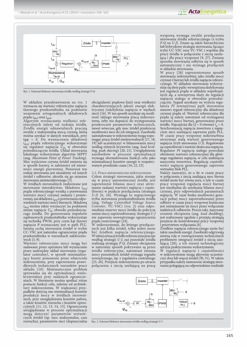
2.2. Praca autonomiczna mikrosystemuCelem strategii sterowania, jakie stosuje się w pracy autonomicznej źródła, jest zapewnienie bilansu mocy oraz utrzy-manie zadanej wartości napięcia i często-tliwości w punkcie przyłączenia (strategia U-f) [6, 24]. Wymaga to napięciowego trybu sterowania przekształtnikiem źródła (ang. Voltage Controlled Voltage Source Conveter, VC-VSC) (rys. 2) oraz odpo-wiedniej rezerwy mocy źródła do pokrycia zmian mocy zapotrzebowanej. Strategia U-f nie zapewnia wewnętrznego ograniczenia prądu zwarciowego [24]. W mikrosystemie, do którego przyłączo-nych jest kilka źródeł, tylko jedno może być źródłem napięcia referencyjnego. W takiej sytuacji źródło referencyjne pracuje według strategii U-f, zaś pozostałe źródła realizują strategię P-Q. Zmiany obciążenia w naturalny sposób pokrywane są przez źródło referencyjne, natomiast zmiana mocy pozostałych źródeł wymaga sygnału zewnętrznego, np. z regulatora centralnego [25, 26]. Przejście mikrosystemu po utracie połączenia z siecią zasilającą na pracę
wyspową wymaga zwykle przełączenia sterowania źródła referencyjnego (z trybu P-Q na U-f). Znane są także hierarchiczne lub hybrydowe strategie sterowania, łączące tryby CC-VSC oraz VC-VSC i wspólne dla pracy źródła w połączeniu z siecią zasila-jącą i dla pracy wyspowej [9, 27]. Zmiana sposobu sterowania odbywa się w sposób automatyczny i nie wymaga przełączeń w układzie sterowania. W pracy [28] zaprezentowano sposób sterowania mikroturbiny, jako źródła mocy czynnej i biernej lub źródła napięcia referen-cyjnego. W układzie sterowania wykorzy-stuje się dwie pętle: wewnętrzna dedykowana jest regulacji prądu w układzie współrzęd-nych dq, a zewnętrzna służy do regulacji napięcia stałego w obwodzie pośredni-czącym. Sygnał uzyskany na wyjściu regu-latora PI zewnętrznej pętli sterowania stanowi sygnał referencyjny dla składowej czynnej prądu id. Wartość referencyjna dla prądu iq zależy natomiast od wymaganej wartości mocy biernej, generowanej przez źródło. Najczęściej dla Q = 0 również iq = 0. Synchronizację napięcia inwertora z napię-ciem sieci zasilającej zapewnia pętla PLL. W czasie pracy wyspowej mikroturbina utrzymuje stałą wartość generowanego napięcia (tryb sterowania U-f). Regulowane są częstotliwość i wartość skuteczna napięcia. Regulator PI napięcia stałego powoduje obniżenie wartości referencyjnej dla głów-nego regulatora napięcia, w celu uniknięcia nasycenia inwertora. Regulację częstotli-wości napięcia generowanego zapewnia wirtualny blok PLL.Należy zauważyć, że o ile w czasie pracy w połączeniu z siecią zasilającą moc bierna źródeł może być równa zeru, o tyle w czasie pracy wyspowej regulacja mocy biernej jest niezbędna do uzyskania bilansu mocy czynnej, przy odpowiednich parametrach napięcia. W razie braku możliwości gene-racji pełnej mocy zapotrzebowanej przez odbiory w czasie pracy wyspowej konieczne jest zmniejszenie tej mocy przez wyłączenie niektórych odbiorów. Proces taki, nazywany zrzutem obciążenia (ang. load shedding), jest realizowany zgodnie z przyjętą strategią przejścia do kontrolowanej pracy wyspowej i priorytetem wyłączania [6]. Źródłem napięcia referencyjnego może być także zasobnik energii. Zasobniki odgrywają istotną rolę w rozwiązywaniu technicznych problemów integracji źródeł z siecią zasi-lającą [20], a ich rozwój technologiczny sprzyja praktycznemu wykorzystaniu.W regulacji napięcia i częstotliwości w mikrosystemie mogą aktywnie uczestni-czyć dwa lub więcej źródeł [30, 31]. W takim przypadku należy zastosować strategię stero-wania polegającą na odpowiednim rozdziale
Rys. 1. Schemat blokowy sterowania źródła według strategii P-Q
Rys. 2. Schemat blokowy sterowania źródła według strategii U-f
I. Wasiak et al. | Acta Energetica 4/21 (2014) | translation 156–163

166
obciążenia pomiędzy źródła. Sterowanie rozdziałem obciążenia w układzie wielu źródeł stanowi odrębne zagadnienie i jest w ostatnim czasie przedmiotem wielu publi-kacji, m.in. [29, 32, 33, 34, 35]. Zagadnienie to zostanie podjęte przez autorów w kolej-nych pracach.
3. Mikrosystem testowyW Laboratorium Generacji Rozproszonej Instytutu Elektroenergetyki Politechniki Łódzkiej [36] skonfigurowano mikrosystem niskiego napięcia o typowej konfiguracji promieniowej, do którego przyłączono: panele fotowoltaiczne o mocy znamionowej 6 kWp, mikroturbinę gazową Capostone C30 o mocy znamionowej 30 kW, bateryjny zasobnik energii o mocy znamionowej 10 kW oraz odbiory liniowe R, L, których moc może być zmieniana za pomocą auto-transformatora regulacyjnego w zakresie 0–30 kW (rys. 3). Panele fotowoltaiczne jako źródła niesterowalne pracują w sposób ciągły z mocą maksymalną, możliwą do uzyskania w danych warunkach. Zasobnik energii jest przyłączany do sieci przez inwertory Sunny Island 4500. Zarówno mikroturbina, jak i zasobnik wyposażone są w fabrycznie zaimplementowane układy sterowania, umożliwiające pracę zarówno w trybie stero-wania prądowego, jak i napięciowego. Tryb sterowania prądowego mikroturbiny jest realizowany zwykle podczas pracy w połączeniu z siecią zasilającą (ang. Grid Connected Mode). Turbina może pracować z zadaną mocą w zakresie 0–30 kW, przy czym zmiany mocy są realizowane zdalnie za pomocą fabrycznej aplikacji Capstone Remote Monitoring System, ewentualnie przez panel sterowniczy znajdujący się na turbinie. W zależności od potrzeb można zaprogramować dobowy i tygodniowy harmonogram pracy lub sterować mocą na bieżąco, według harmonogramu wyzna-czonego przez zewnętrzny układ sterowania. Zanik napięcia zasilającego powoduje awaryjne zatrzymanie się turbiny. Ponowne uruchomienie i tryb przyjętej pracy uzależ-nione są od nastaw parametru Power Connect:• Grid Connect – turbina powraca do pracy
w połączeniu z siecią jako źródło prądowe• Stand Alone – turbina rozpoczyna pracę
autonomiczną i jest źródłem napięcia referencyjnego
• Dual Mode – w zależności od konfi-guracji sieci oraz obecności/braku napięcia referencyjnego, turbina pracuje w trybie Grid Connect albo Stand Alone.
Zasobnik połączony z siecią zasilającą pracuje w trybie RUN_I inwertora i, podobnie jak mikroturbina, synchronizuje się z napięciem i częstotliwością sieci. Pobór prądu przez zasobnik zależy od typu i stanu nałado-wania baterii. Przy zaniku napięcia sieci zasobnik może pełnić funkcję UPS (prąd ograniczony jest do 70 A, a czas pracy w trybie UPS wynosi maksymalnie 5 s), bądź od razu przejść do trybu pracy wyspowej RUN_U jako źródło napięcia referencyj-nego i mocy. Żadne z urządzeń nie umoż-liwia pracy w trybie sterowania napięciowego przy obecności napięcia w sieci, do której jest przyłączone. Jak wynika z przedstawionego opisu, praca autonomiczna mikrosystemu jest możliwa w dwóch wariantach:• zasobnik jest źródłem napięcia referencyj-
nego (RUN_U), a mikroturbina pracuje w trybie Grid Connected Mode
• mikroturbina jest źródłem napięciowym (ang. Stand Alone Mode), a zasobnik pracuje w trybie RUN_I.
Badania pracy mikrosystemu testowego przeprowadzono w obu wariantach. Dla oceny możliwości regulacyjnych urządzeń, które mogą być źródłem napięcia referen-cyjnego, w pierwszej kolejności pomierzono ich charakterystyki statyczne.
4. Charakterystyki statyczne źródeł energiiBadania mikroturbiny gazowej i elektro-chemicznego zasobnika energii wyko-nano kolejno przy obciążeniu czysto rezy-stancyjnym, a następnie reaktancyjnym o charakterze indukcyjnym, w zakresie odpowiadającym znamionowej obcią-żalności źródeł. W przypadku zasobnika dodatkowo wykonano pomiary dla stanu ładowania, wykorzystując mikroturbinę jako źródło mocy. Na rys. 4 i 5 pokazano pary charakterystyk statycznych mikroturbiny gazowej, odpo-wiednio U = f(P) i f = f(P) oraz U = f(Q) i f = f(Q). Prezentowane wyniki wskazują, że mikroturbina utrzymuje praktycznie stałą wartość częstotliwości w całym zakresie obciążenia, zarówno mocą czynną, jak i bierną. Nachylenia charak-terystyk częstotliwościowych wynoszą –0,001 Hz/kW i –0,001 Hz/kvar. Zmiana napięcia mikroturbiny wynosi –0,13 V/kW oraz –0,32 V/kvar. Analogiczne pary charakterystyk, wyzna-czone dla zasobnika energii, przedstawiono na rys. 6–7. Jak wynika z pomiarów, zmiana częstotliwości napięcia zasobnika wynosi –0,1 Hz/kW oraz –0,01 Hz/kvar. Nachylenie charakterystyki napięciowej zasobnika zależy od fazy pracy (ładowanie/rozładowanie) i w zakresie ładowania wynosi –0,56 V/kW, a w zakresie obciążenia –1,27 V/kW. Przebieg charakterystyki napięciowej zasobnika w funkcji mocy biernej jest nieliniowy i wykazuje dużą zmienność.
Rys. 3. Schemat mikrosystemu do badań testowych
200
205
210
215
220
225
230
235
240
0 5000 10000 15000 20000Q[var]
U[V
]
48,0
48,5
49,0
49,5
50,0
50,5
51,0
51,5
52,0
f [H
z]
Uf
200
205
210
215
220
225
230
235
240
0 5000 10000 15000 20000 25000 30000P[W]
U[V
]
48,0
48,5
49,0
49,5
50,0
50,5
51,0
51,5
52,0
f[Hz]
Uf
Rys. 4. Charakterystyki statyczne U = f(P) i f = f(P) mikroturbiny
Rys. 5. Charakterystyki statyczne U = f(Q) i f = f(Q) mikroturbiny
I. Wasiak et al. | Acta Energetica 4/21 (2014) | translation 156–163
167
Na podstawie przeprowadzonych badań można stwierdzić, że mikroturbina gazowa jest lepszym źródłem napięcia referen-cyjnego, gdyż zapewnia bardziej stabilne warunki zasilania odbiorów (posiada sztyw-niejsze charakterystyki statyczne) w szer-szym zakresie obciążenia. Wadą mikrotur-biny jest brak możliwości magazynowania energii.
5. Praca autonomiczna – badania obiektowe5.1. Wariant I (źródłem referencyjnym w mikrosystemie jest zasobnik)Test przeprowadzono przy założeniu stałej mocy generowanej przez turbinę: Pt = 2,7 kW i Qt = 0. Moc czynna wytwa-rzana przez panele fotowoltaiczne wahała się w granicach PPV = 2,8–3,7 kW, przy mocy biernej QPV = 0. W czasie testu zmieniano pięciokrotnie moce obciążenia, ich wartości podano w tab. 1. Bilans mocy czynnej w mikrosystemie przy zmianach mocy odbiornika pokazano na rys. 8. Widoczna jest na nim bilansu-jąca rola zasobnika, który przez większość
okresu pomiarowego pełnił funkcję odbior-nika, tzn. magazynował nadmiar energii w mikrosystemie. Przy krótkotrwałym wzro-ście obciążenia powyżej 6,6 kW zasobnik stał się źródłem energii.
Na rys. 9 przedstawiono bilans mocy biernej w mikrosystemie w badanym okresie. Moc bierna mikroturbiny (równa 0,25 kVar) odpowiada mocy biernej traconej w jej
obwodzie przyłączeniowym. Analogicznie, moc bierna źródła fotowoltaicznego (zmie-niająca się w zakresie 390–580 Var) odpo-wiada mocy biernej traconej w przyłączu. Zasobnik bilansuje zmiany mocy biernej w mikrosystemie. Na podstawie przeprowadzonych pomiarów sporządzono charakterystyki statyczne U = f(S) i f = f(S) zasobnika energii jako źródła napięcia referencyjnego (rys. 10). Występuje w nich wyraźna zależność wartości napięcia i częstotliwości od poziomu obciążenia. Nachylenie charakterystyki napięciowej jest równe –7,2 V/kVA, a częstotliwościowej –0,2 Hz/kVA.
5.2. Wariant II (źródłem referencyjnym w mikrosystemie jest mikroturbina)Harmonogram zmian mocy obciążenia w czasie testu obejmował kolejno wartości podane w tab. 2.Moc wytwarzana przez źródło PV zmie-niała się w zakresie od PPV = 2,6 kW do PPV = 0,25 kW. Zasobnik został załączony o godz. 14:37 i po załączeniu pobierał moc ładowania (pracował jako odbiornik).Na rys. 11 pokazano bilans mocy czynnej, a na rys. 12 bilans mocy biernej w mikro-systemie przy zmianach mocy odbiornika. W tym wariancie pracy mikrosystemu mikroturbina jako źródło napięciowe pełni funkcję elementu bilansującego i pokrywa zmiany mocy czynnej i biernej.Charakterystyki statyczne U = f(S) i f = f(S) mikroturbiny jako źródła referencyjnego przedstawiono na rys. 13. Zależność wartości napięcia i częstotliwości od poziomu obcią-żenia jest w tym przypadku znacznie mniejsza i wynosi odpowiednio –0,3 V/kVA oraz –0,002 Hz/kVA.Zarówno mikroturbina, jak i bateryjny zasobnik energii jako źródła napięcia refe-rencyjnego mogą pełnić funkcję bilanso-wania mocy w mikrosystemie. Mikroturbina zapewnia większy zakres produkowanej mocy i możliwość długo-trwałej pracy autonomicznej, gdy moc obciążenia jest większa od mocy produko-wanej w pozostałych źródłach. Przy dużej produkcji mocy źródeł i małym obciążeniu sieci konieczne jest zainstalowanie zasob-nika jako odbiornika energii lub ograni-czanie mocy źródeł.
Rys. 6. Charakterystyki statyczne U = f(P) i f = f(P) elektrochemicznego zasobnika energii
Rys. 8. Bilans mocy czynnej w mikrosystemie dla wariantu I
Rys. 7. Charakterystyki statyczne U = f(Q) i f = f(Q) elektrochemicznego zasobnika energii
Tab. 1. Zmiany mocy obciążenia w czasie testu dla wariantu I pracy mikrosystemu
200
205
210
215
220
225
230
235
240
-4000 -2000 0 2000 4000 6000 8000 10000P[W]
U[V
]
48,0
48,5
49,0
49,5
50,0
50,5
51,0
51,5
52,0
f [H
z]
Uf
200
205
210
215
220
225
230
235
240
0 2000 4000 6000 8000 10000Q[var]
U[V
]
48,0
48,5
49,0
49,5
50,0
50,5
51,0
51,5
52,0
f [H
z]
Uf
P [kW] 1,3 2,8 4,8 6,1 4,2
Q [kvar] 0,9 2,6 4,6 5,9 4,0
-8 000
-6 000
-4 000
-2 000
0
2 000
4 000
6 000
8 000
10 000
12 000
13:00 13:05 13:10 13:15 13:20 13:25 13:30 13:35 13:40 13:45t [gg:mm]
P [W
]
P mikroturbinyP zasobnikaP fotowoltaikiP odbiornika
I. Wasiak et al. | Acta Energetica 4/21 (2014) | translation 156–163

168
6. Wnioski końcoweMikrosystemy elektroenergetyczne niskiego napięcia z rozproszonymi źródłami energii stwarzają nowe możliwości i mogą przy-czynić się do zwiększenia niezawodności dostawy energii elektrycznej do odbiorców. Mikrosystem może utrzymać zasilanie odbiorców w czasie utraty połączenia z siecią energetyki zawodowej pod warun-kiem odpowiedniej mocy źródeł i właściwej strategii sterowania.
Badania przeprowadzone w mikro-systemie testowym w Laboratorium Generacji Rozproszonej, w Instytucie Elektroenergetyki Politechniki Łódzkiej, umożliwiły określenie właściwości mikro-turbiny gazowej i bateryjnego zasobnika energii jako potencjalnych źródeł napięcia referencyjnego podczas krótkotrwałej pracy autonomicznej mikrosystemu. Wyniki badań są podstawą dalszych prac zmierzających do określenia metody doboru
architektury mikrosystemu i strategii stero-wania uwzględniającej współpracę zasob-nika energii oraz źródeł sterowalnych.
Bibliografia
1. Driesen J., Katiraei F., Design for Distributed Energy Resources, IEEE Power & Energy Magazine 2008, No. 8.
2. Bollen M.H-J., Yang Y., Hassan F., Integration of Distributed Generation in the Power System – A Power Quality Approach, Proc. 13th International Conference on Harmonics and Quality of Power, Wollongong, Australia 28.09–1.10 2008.
3. Katiraei F. i in., Microgrid Management. Controls and Operation Aspects of Microgrids, IEEE Power & Energy Magazine, May/June 2008.
4. I E E E 1 5 4 7 : S t a n d a r d f o r Interconnecting Distributed Resources with Electric Power Systems.
5. IRiESD, Instrukcja Ruchui Eksploatacji Sieci Dystrybucyjnych, PGE Łódź – Teren, 2009.
6. Balaguer I.J. i in., Intelligent Control for Intentional Islanding Operation of Microgrids, ISCET 2008.
7. Gomez J.C., Morcos M.M., Distributed Generation: Exploitation of Islanding Operation Advantages, IEEE/PES Transmission and Distribution Conference and Exposition: Latin America, 2008.
8. Piargi P., Lasseter R.H., Autonomous Control of Microgrids, IEEE PES General Meeting, 2006.
9. Gao F., Iravani M.R., A Control Strategy for a Distributed Generation Unit in Grid Connected and Autonomous Modes of Operation, IEEE Trans. on Power Delivery April 2008, Vol. 23, No. 2.
10. Colson C.M., Nehir M.H., A Review of Challenges to Real-Time power Management of Microgrids, IEEE Power & Energy Society General Meeting, 2009.
11. Alvarez E. i in., On-line Minimization of Running Costs, Greenhouse Gas Emission and the Impact of Distributed Generation using Microgrids on the Electrical System, IEEE PES/IAS Conference on Sustainable Alternative Energy, 28–30.09.2009.
12. Gu W., Wu Z., Yuan X., Microgrid Economic Optimal Operation of the Combined Heat and Power System with Renewable Energy, IEEE Power Energy Soc. Gen. Meet., 25–29 July 2010.
13. Hernandez-Aramburo C.A., Green T.C., Fuel Consumption Minimisation of a Micro-grid, Industry Application Conference, 39th IAS Annual Meeting, 3–7.10.2004.
14. Mohamed F.A., Koivo H.N., On-line Management of MicroGrid with Battery Storage Using Multiobjective
Rys. 9. Bilans mocy biernej w mikrosystemie dla wariantu I
Rys. 10. Charakterystyki statyczne zasobnika energii dla wariantu I pracy mikrosystemu
Rys. 11. Bilans mocy czynnej w mikrosystemie dla wariantu II
Tab. 2. Zmiany mocy obciążenia w czasie testudla wariantu I pracy mikrosystemu
-8 000
-6 000
-4 000
-2 000
0
2 000
4 000
6 000
8 000
10 000
12 000
13:00 13:05 13:10 13:15 13:20 13:25 13:30 13:35 13:40 13:45t [gg:mm]
Q [v
ar]
Q mikroturbinyQ zasobnikaQ fotowoltaikiQ odbiornika
200
205
210
215
220
225
230
235
240
3 000 3 500 4 000 4 500 5 000 5 500 6 000S [VA]
U [V
]
48,0
48,5
49,0
49,5
50,0
50,5
51,0
51,5
52,0
f [H
z]
Uf
P [kW] 5,9 9,5 13,6 4,2
Q [kvar] 5,3 8,1 11,5 3,9
-25 000
-20 000
-15 000
-10 000
-5 000
0
5 000
10 000
15 000
20 000
25 000
14:20 14:25 14:30 14:35 14:40 14:45 14:50 14:55t [gg:mm]
P [W
]
P mikroturbinyP zasobnikaP fotowoltaikiP odbiornika
I. Wasiak et al. | Acta Energetica 4/21 (2014) | translation 156–163

169
Optimization, International Conference on Power Engineering, Energy and Electrical Drive POWERENG 2007, 12–14.04.2007.
15. Vahedi H., Noroozian R., Hosseini S.H., Optimal Management of MicroGrid Using Differential Evolution Approach, 7th International Conference on the European Energy Market (EEM), 23–25 June 2010.
16. Gburczyk P. i in., Management System as a Mean for the Integration of Distributed Energy Sources with Low Voltage Network, IEEE International Conference on Electrical Power Quality and Utilisation (EPQU ’2011), Lisbon (Portugal), 17–19 October 2011, s. 1–5.
17. Barote L., Georgescu M., Marinescu C., Smart Storage Solution for Wind Systems, IEEE Power Tech Conference, Bucharest, Romania, 28.06–2.07 2009.
18. Faias S. i in., Evaluation of Energy Storage Devices for Renewable Energies
Integration, Application to a Portuguese Wind Farm, 5th Int. Conference on European Electricity Market (EEM 2008), Lisbon, Portugal, 2008.
19. Qian K. i in., Benefits of Energy Storage in Power Systems with High Level of Intermittent Generation, 20th Int. Conference on Electricity Distribution (CIRED2009), Praque, 8–11.06.2009.
20. Wasiak I., Pawełek R., Mieński R., Zasobniki energii w mikrosystemach elektroenergetycznych, konferencja „Aktualne problemy w elektroenergetyce”, APE ’11, Jurata, 8–10.06.2011, s. 159–166.
21. Zamora R., Srivastava A.K., Controls for Microgrids with Storage: Review, Challenges, and Research Needs, Renewable and Sustainable Energy Reviews 2010, No. 14, s. 2009–2018.
22. Chakraborty S., Simoes M.G., PV-Microgrid Operational Cost Minimization by Neural Forecasting
and Heuristic Optimization, Industry Applications Society Annual Meeting, IAS ’08 IEEE, 2008.
23. Guan X., Xu Z., Jia Q.-S., Energy-efficient Buildings Facilitated by Microgrid, IEEE Trans. on Smart Grid 2011, Vol. 2, No. 1.
24. Gao F., Iravani M.R., A Control Strategy for a Distributed Generation Unit in Grid Connected and Autonomous Modes of Operation, IEEE Trans. On Power Delivery, Vol. 23, No. 2, April 2008.
25. Chowdhury S.P. i in., Operation and control of DG based power island in Smart Grid environment, 20th Int. Conference and Exhibition on Electricity Distribution, CIRED 2009.
26. Ghadimi A.A., Razavi F., Ghaffarpour R., Control of Islanded Inverter Interfaced Distributed Generation Units For Power Quality Improvement, 14th Int. Conference on Harmonics and Quality of Power, ICHQP 2010.
27. Delghavi M.B., Yazdani A., A Unified Control Strategy for Electronically Interfaced Distributed Energy Resources, IEEE Trans. on Power Delivery 2012, Vol. 27, No. 2.
28. Gaonkar D.N., Patel R.N., Pillai G.N., Dynamic Model of Microturbine Generation System for Grid Connected/islanding operation, IEEE Int. Conference on Industrial Technology, ICIT 2006.
29. Sao C.K., Lehn P.W., Control and Power Management of Converter Fed Microgrids, IEEE Trans. on Power Systems August 2008, Vol. 23, No. 3.
30. Katiraei F., Iravani R., Power Management Strategies for a Microgrid with Multiple Distributed Generation Units, IEEE Transaction on Power Systems 2006, Vol. 21, No. 4.
31. Pecas Lopes J.A., Moreira C.L., Madureira A.G., Defining Control Strategies for Microgrids Islanded Operation, IEEE Transaction on Power System May 2006, Vol. 21, No. 2.
32. Brabandere K. i in., A Voltage and Frequency Droop Control Method for Parallel Inverters, IEEE Transaction on Power Electronics July 2007, Vol. 22, No. 4.
33. Majumder R. i in., Load Sharing and Power Quality Enhanced Operation of a Distributed Microgrid, IET Renewable Power Generation 2009, Vol. 3, Iss. 2.
34. Majumder R. i in., Droop Control of Converter-Interfaced Microsources in Rural Distributed Generation, IEEE Trans. on Power Delivery October 2010, Vol. 25, No. 4.
35. Vandoorn T. i in., A Control Strategy for Islanded Microgrids with DC-link Voltage Control, IEEE Trans. on Power Delivery April 2011, Vol. 26, No. 2.
36. Pawełek R. i in., Mikrosystem – węzeł ener-getyczny w Instytucie Elektroenergetyki Politechniki Łódzkiej, konferencja „Aktualne problemy w elektroenergetyce”, APE ’11, Jurata, 8–10.06.2011, s. 143–150.
Rys. 12. Bilans mocy biernej w mikrosystemie dla wariantu II
Rys. 13. Charakterystyki statyczne mikroturbiny dla wariantu II pracy mikrosystemu
-15 000
-10 000
-5 000
0
5 000
10 000
15 000
14:20 14:25 14:30 14:35 14:40 14:45 14:50 14:55t [gg:mm]
Q [v
ar]
Q mikroturbinyQ zasobnikaQ fotowoltaikiQ odbiornika
200
205
210
215
220
225
230
235
240
0 5 000 10 000 15 000 20 000 25 000S [VA]
U [V
]
48,0
48,5
49,0
49,5
50,0
50,5
51,0
51,5
52,0
f [H
z]
Uf
I. Wasiak et al. | Acta Energetica 4/21 (2014) | translation 156–163

170
Irena Wasiakdr hab. inż., prof. nadzw.Politechnika Łódzkae-mail: [email protected] Politechniki Łódzkiej. Od początku kariery zawodowej pracuje w Instytucie Elektroenergetyki tej uczelni. Uzyskała stopnie naukowe doktora i doktora habilitowanego z dziedziny elektroenergetyki. W latach 2002–2008 była prodziekanem Wydziału Elektrotechniki, Elektroniki, Informatyki i Automatyki PŁ. Obecnie pełni funkcję kierownika Zakładu Sieci Elektroenergetycznych Mikrosystemów. Członkini The Institution of Engineering and Technology oraz Komitetu ds. Jakości i Efektywnego Użytkowania Energii Elektrycznej SEP, członek stowarzyszony Sekcji Systemów Elektroenergetycznych PAN. Pełni funkcję zastępcy redaktora naczelnego czasopisma Electrical Power Quality and Utilisation oraz współprzewodniczącej międzynarodowej konfe-rencji o tej samej nazwie. Obszar działalności naukowej obejmuje zagadnienia jakości zasilania, integracji rozproszonych źródeł energii w sieciach elektroener-getycznych, funkcjonowania mikrosystemów elektroenergetycznych.
Ryszard Pawełekdr inż.Politechnika Łódzkae-mail: [email protected] Wydziału Elektrycznego Politechniki Łódzkiej (1977). Obecnie jest zatrudniony w Instytucie Elektroenergetyki swojej macierzystej uczelni na stanowisku adiunkta, gdzie pełni funkcję zastępcy dyrektora Instytutu. Obszar zainteresowań naukowych obejmuje: jakość energii elektrycznej, generację rozproszoną, mikrosystemy elektroenergetyczne. Jest członkiem Polskiego Komitetu Jakości i Efektywnego Użytkowania Energii Elektrycznej, w którym pełni funkcję wiceprzewodniczącego ds. nauki. Rzeczoznawca SEP w dziedzinie jakości energii elektrycznej.
Paweł Kelmdr inż.Politechnika Łódzkae-mail: [email protected] Wydziału Elektrotechniki, Elektroniki, Informatyki i Automatyki Politechniki Łódzkiej (2004). Pracę doktorską obronił na swojej macierzystej uczelni (2012). Pracował na The University of Strathclyde w Glasgow (2007–2008). Zatrudniony na stanowisku adiunkta w Instytucie Elektroenergetyki
I. Wasiak et al. | Acta Energetica 4/21 (2014) | translation 156–163