autonomous formation flight of indoor uavs based on model...
TRANSCRIPT

American Institute of Aeronautics and Astronautics
1
Autonomous Formation Flight of Indoor UAVs
Based on Model Predictive Control
Shixin Mao1, Wee Kiat Tan2, and K. H. Low3
School of Mechanical and Aerospace Engineering, Nanyang Technological University, Singapore 639798
This paper presents the autonomous formation flight of indoor UAVs based on Model
Predictive Control (MPC). Dynamic model was built for the analysis of the quadcopter
platform and the utilization of MPC. Several telemetry modules were tested for its
performance for indoor application using MAVLink. The trajectory simulation is performed
to verify the effectiveness of the utilized control method. The Vicon motion capture system
was employed for tracking quadcopters, recording data and testing the flight formation
control. Formation flight experiments are conducted to verify the performance of the MPC
for the autonomous formation of UAVs. Finally, the Air Traffic Management (ATM)
concept with avoidance, geo-fencing as well as take over control were demonstranted in an
indoor simulated environment.
Nomenclature
T1, T2, T3, T4= lift force of four rotors
ɸ, θ, ψ = the Euler angles
I11, I22, I33 = the moment of inertial of the xyz axes in the body frame Oxyz
p, q, r = the angular velocities
Mx, My, Mz= the moments around each axis of the Oxyz frame
I. Introduction
NMANNED Aerial Vehicles (UAVs) are aerial vehicles which operate without a human pilot on board.1,2 Its
flight path is either controlled autonomously by onboard or ground computers, or remote control by a human
operator on the ground or vehicle. Quadcopters are quite common UAVs.3,4 With the current increasing trend for
multirole purpose UAVs, cooperative behavior for multiple UAVs can be used as enhanced capabilities to share
information and complete different operations such as intelligence surveillance, reconnaissance and wide area search
or destroy.5-7 However, cooperative control of UAVs is a complicated problem due to the task coupling, high degree
of uncertainties in a dynamic environment and limited information etc.8
In formation flight control, the main issues are the stability, complexity and the implementation feasibility under constraints. Several nonlinear formation flight control methodologies9-12 were developed for aerial vehicles. Compared with the linear formation flight controller, the nonlinear ones are to compensate the model/aerodynamics uncertainties and disturbances during formation flight by using gain scheduling technique and adaptive control methods. This allows the formation flight to operate in much wider range than using the linear formation flight controller. However, most of the nonlinear formation flight controllers9-11 still cannot directly deal with input/states constraints. Also the obstacle avoidance is often not considered in the framework.
Model Predictive Control (MPC) is developed for the formation flight control.13,14 It has the advantage of handling constraints. Secondly, the leader-follower scheme is used to prescribe a coordinated behavior.15 In Model Predictive Control,16,17 the feedback control inputs are acquired via repeatedly overcoming an optimal control problem featured with online open loop. The problem is posed at each sampled time and by updating the initial condition with the current state, it is solved over a finite time horizon longer than the sampling time. It is one of the few control methods that are able to incorporate constraints on both output and inputs. Applications of MPC to fast dynamical control
1 Research Fellow, School of Mechanical&Aerospace Engineering, 50 Nanyang Avenue, Singapore 639798. 2 Project Officer, School of Mechanical & Aerospace Engineering, 50 Nanyang Avenue, Singapore 639798. 3 Professor, School of Mechanical & Aerospace Engineering, 50 Nanyang Avenue, Singapore 639798.
U

American Institute of Aeronautics and Astronautics
2
problems have started to emerge in recent years.18 Neural Network based MPC is applied to F-16 models in Ref. 19 robots in Ref. 20, and UAVs in Refs. 21-23.
The controller type used in many references can be categorized into the linear proportional-integral-derivate (PID) controller.24,25 A formation flight controller (i.e., a formation-hold autopilot for the wingman) was designed with such that formation’s geometry is maintained when facing with the leader maneuverer as described in Ref. 24. The additional aerodynamic coupling effects introduced by tight formation flight are modelled. The most significant aerodynamic coupling effect introduced by tight formation entails the coupling of the lateral or directional channel into the altitude-hold autopilot channel. The organization of the rest of this paper is as follows. The quadcopter prototype and dynamics are fabricated and built in section II. Details about the MPC and the robust linear feedback controller literature review, formulation and implementation are discussed in section III. Autonomous flight experiments with four quadcopters and results are presented in section IV. The simulation and experiment are performed in Section III and section IV to verify the effectiveness of the employed control method. Finally, we conclude the paper in the last section.
II. UAV Mechanism and Dynamics
A. UAV Description
We have developed several drones together with a program that can control and coordinate a group of them. The
main structure and experimental setup are as shown in Figure 1(a), 1-20cm propeller (made of plastic for safety
reasons); 2-Frame protector (carbon fibre frame that protects the propellers);3-Reflective marker balls (allow an
overhead camera system to track the drone’s location); 4-Data link circuit boards (allow computer to send
instructions to the drone); 5-Radio control receiver (allows the drone to be controlled by a remote controller); 6-
Propeller motor (can spin attached propeller by up to 10,000 rpm); 7-Switch (to power on and off the drone); 8-
Controller board (has sensors that help the drone maintain its balance and fly to a specific location); 9-Battery buzzer
(buzzes when the drone is close to running out of battery); 10-Battery (2,200mAh lithium polymer battery); 11-
Voltage regulator (adjusts the voltage supplied to various components); 12-Electronic speed controller (controls the
speed of one propeller).
(a) (b)
Figure 1 (a) Top view of quadcopter experimental setup; (b) Configuration of quadcopter.26
B. State Dynamics This section will cover the dynamic equations that describe the quadcopter state information. In the quadcopter
configuration as shown in Figure 1(b), the throttle input is the sum of the thrusts of each motor. The pitch movement is controlled by increasing T1 and reducing T3 and vice versa. The roll movement is controlled by increasing T4 while reducing T2 and vice versa. The yaw is controlled by increasing the speed of T2 and T4 while decreasing T1 and T3 and vice versa.
To describe the quadcopter dynamics, two coordinate systems are required. One is the earth fixed frame denoted
by ONED (North-East-Down) and the second is the mobile body frame denoted by Oxyz, whose dynamic behaviour
can be described related with the earth fixed frame. The mobile body frame origin will be coincident with the
quadcopter’s centre of gravity.8,12,20

American Institute of Aeronautics and Astronautics
3
The translation dynamics is given as follows:13,15,22
( )
( ) (1)
( )
mX c s c s s
mY s s c c s
mZ mg c c
T
T
T
where [X Y Z] is the position of the centre of gravity in the frame ONED, [ɸ θ ψ] are the Euler angles, note that c =
cos() , s= sin() and T = -(T1+ T2 + T3 + T4). The rotational dynamics can be expressed as:
33 22
11 11
11 33
22 22
22 11
33 33
( )
( )(2)
( )
x
y
z
M I I qr
I Ip
M I I prq
I Ir
M I I pq
I I
where I11, I22, and I33 are the moment of inertial of the xyz axes in the body frame Oxyz, [p q r] are the angular
velocities and [Mx My Mz] are the moments around each axis of the Oxyz frame.
Using the strap-down equation:14,16
1
0 (3)
0 / /
tan s tan c p
c s q
s c c c r
The rotational equation in terms of Euler angles ƞ = [ɸ θ ψ]T can be written in general form, as follows:
( ) (4)M C
By combing equations, the quadcopter model can be represented into a state-space compact form:
= ( , ) (5)X f x u
III. Formation Flight Control
A. Control Method In this section, the formation pair (one leader and three wingman quadcopter) controllers are reviewed. For formation flight control problem, normally formation control about scheme and architecture, and the formation pair controller design is decoupled and treated separately. The formation flight control strategy implemented was a two tiered structure. The upper tier is designed as guidance for the flight formation. This consists of velocity, heading, and altitude controls for the formation. The lower tier is specified to control the actual formation geometry. This consists of x, y and z separation distances between the leader and wingmen in the formation. The structure of this mixed PID formation flight controller. The main weaknesses of this approach are the lack of capability to include the input/states constraints in the design and its relatively low range of flight condition validity. This scheme uses one agent to be designated as the leader and the remaining agents will follow the leader’s motion offset by a relative position.27,28-30 In this scheme, it is assumed only the leader will receive the command. The advantage of a leader-follower scheme is that the formation flight ground maneuvers is able to be specified in terms of the leader’s motion. However it also has a disadvantage, which is the leader’s motion, is independent from the rest of the follower agents. This means that if the follower agents impossible to maintain a little tracking error, the formation will be broken as the leader will continue moving at its own pace while the tracking error becoming bigger.
B. Vicon System The Vicon system (so called motion capture system) uses software which is called Vicon Tracker. This software has several features that will help in testing the flight control algorithms. It is able to track 50 unique objects simultaneously; Recognize rigid bodies in 2D so even if the markers visible to one camera, the data can still continue; Low latency in streaming object locations; Its validated latency is 2.5 msec. The Vicon lab area for the experiment is approximate area of 10 meter in length and 9 meter in width. But the cameras coverage can only
American Institute of Aeronautics and Astronautics
4
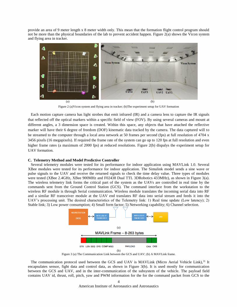
provide an area of 9 meter length x 8 meter width only. This mean that the formation flight control program should not be more than the physical boundaries of the lab to prevent accident happen. Figure 2(a) shows the Vicon system and flying area in tracker.
(a) (b)
Figure 2 (a)Vicon system and flying area in tracker; (b)The experiment setup for UAV formation
Each motion capture camera has light strobes that emit infrared (IR) and a camera lens to capture the IR signals
that reflected off the optical markers within a specific field of view (FOV). By using several cameras and mount at
different angles, a 3 dimension space is created. Within this space, any objects that have attached the reflective
marker will have their 6 degree of freedom (DOF) kinematic data tracked by the camera. The data captured will to
be streamed to the computer through a local area network at 50 frames per second (fps) at full resolution of 4704 x
3456 pixels (16 megapixels). If required the frame rate of the system can go up to 120 fps at full resolution and even
higher frame rates (a maximum of 2000 fps) at reduced resolutions. Figure 2(b) dispalys the experiment setup for
UAV formation.
C. Telemetry Method and Model Predictive Controller
Several telemetry modules were tested for its performance for indoor application using MAVLink 1.0. Several
XBee modules were tested for its performance for indoor application. The Simulink model sends a sine wave or
pulse signals to the UAV and receive the returned signals to check the time delay value. Three types of modules
were tested (XBee 2.4GHz, XBee 900MHz and F02438 Dual TTL 3DRobotics 433MHz), as shown in Figure 3(a).
The wireless telemetry link forms the critical part of the system as the UAVs are controlled in real time by the
commands sent from the Ground Control Station (GCS). The command interface from the workstation to the
wireless RF module is through Serial communication. Wireless module translates the incoming serial data into RF
and a similar RF transceiver module at the UAV end translates RF data into serial stream and feeds it into the
UAV’s processing unit. The desired characteristics of the Telemetry link: 1) Real time update (Low latency); 2)
Stable link; 3) Low power consumption; 4) Small form factor; 5) Networking capability; 6) Channel selection.
(a)
(b)
Figure 3 (a) The Communication Link between the GCS and UAV; (b) A MAVLink frame.
The communication protocol used between the GCS and UAV is MAVLink (Micro Aerial Vehicle Link),31 It
encapsulates sensor, fight data and control data, as shown in Figure 3(b). It is used mostly for communication
between the GCS and UAV, and in the inter-communication of the subsystem of the vehicle. The payload field
contains UAV id, thrust, roll, pitch, yaw and PWM information for the for the command packet from GCS to the

American Institute of Aeronautics and Astronautics
5
UAV. The main issues in formation flight control are stability, complexity and the implementation feasibility under
constraints. So the type of formation flight architecture, scheme and controller will be centralised control
architecture, a leader-follower scheme and both MPC and nonlinear flight controller. To realize real time formation
flight, a hierarchical control consists of a top layer model predictive controller (MPC) with a bottom layer robust
feedback linearization controller is proposed as in Ref. 26.
The Figure 4 below shows the program flow in MATLAB. The MPC trajectory generator will require two types of
input: constraint inputs and objective inputs. Constraint inputs are parameter that not controllable by the quadcopter
example like the flight path cannot be more than the boundary of the test bed or the quadcopter maximum angle
cannot be more than certain value. The objective inputs are parameters that the quadcopter can control and the MPC
trajectory can optimize it. Example like the quadcopter must reach this position at a specify time and also the
smoothness of the transition. After received the inputs, the MPC trajectory generator will attempt to optimize and
compute a list of trajectory way points so the quadcopter can follow it. After computing the reference trajectory way
points. This data will be used as one of the input in the MATLAB/Simulink program.
Figure 4. Model predictive control program flow and nonlinear controller program flow in MATLAB
During a real time flight, the MATLAB/Simulink main program will be responsible for getting the reference
trajectory data and the VICON Data. However, this main program also has other function like pre-set hover
condition or initial position. It is also capable of having its own programmed simple trajectory data instead of the
reference trajectory data from the MPC trajectory generator. The user will only need to program some equation of
motion in the state flow of the MATLAB/Simulink main program. However, there are limitations on the complexity
of the trajectory path it can handle, as it will get increasingly complex when dealing with increasingly number of
quadcopters and complicated pattern. It will also have latency occur as the ground control station will have
computed the trajectory real time. And then the feedback linearization controller will be doing the real time
computation to ensure that the quadcopter is able to meet and maintain the desired positions. This bottom layer
controller will be computing in real time so it can keep track of the quadcopter positions. At this stage, the controller
will keep outputting the desired data like roll, pitch, yaw and thrust required.
After the controller had output the desired data, these data will pass into the telemetry block in the
MATLAB/Simulink. From here, these data will be sends out to the quadcopters through XBee Pro Series 1. These
proposed two layer formation flight controller will improve the performance of the real time formation flight by
reducing computation burden during the real time flight, as the desired trajectory is already computed before flight.
So the saved computing power can be used to improve the reaction time to correct the error between actual and
desired positions.

American Institute of Aeronautics and Astronautics
6
Figure 5. Simulink interface of the ground control station (rotated view)
The Simulink interface for UAV formation or swarming was also developed where the communication is done
with XBee 2.4GHz module. The telemetry employs MAVLink 1.0 protocol. MAVLink is an open source library for
micro air vehicles. It is currently a famous protocol for UAV community due to its low overhead, reliability and ease
of expansion. MAVLink can be communicated through UDP or UART bridge. Simulink interface that is ready for a
perching experiment is shown in Figure 5. This Simulink model acts as the ground control station to communicate
with the UAV via XBee. It sends Roll, Pitch, Yaw, Thrust, and PWM commands to the UAV using Mavlink 1.0
protocol via serial port at baud rate of 57,600 bps. The Simulink interface can also receive downlink information
(such as attitude information from the UAV that could be useful for debugging purposes).
D. Trajectory Simulation
The MPC will generates the optimized collision-free state reference trajectory which satisfies all kind of
constraints offline by exploiting the quadcopter model and environment information pre-flight first. Then the bottom
layer the robust feedback linearization controller which is designed based on exact dynamics inversion of the
quadcopter, tracks the optimal state reference and suppresses any tracking errors and follows the pre-generated
trajectory path computed by the MPC controller during flight. Figure 6 displays the trajectory simulation during the
formation flight experiment of UAVs.
Figure 6 The trajectory simulation for the formation flight of UAVs

American Institute of Aeronautics and Astronautics
7
IV. Autonomous Flight Experiment with Four Quadcopters
Four quadcopters with 8-inch propellers are used for formation flights and a VICON motion capture system is utilized to measure the position of the quadcopter. The control method is implemented in Matlab (Simulink) and then run on a workstation PC. The control commands are then transmitted to the quadcopter via wireless communication.
Figure 7. Autonomous formation flight of four indoor quadcopters
Figure 8 Trajectory data output (desired position x, y, and yaw) of UAVs
The quadcopters will take-off to 1.2m height at the position 0.1m away from the starting point, and then be commanded to fly to target positions with formation following the planned trajectory. The measured values from Vicon are recorded for further analysis. Since only the case of two dimensions is considered, the lateral and vertical positions of the quadcopters are kept constant during the flying procedure. Figure 7 displays the entire process of autonomous formation flight of indoor quadcopters. We are able to acquire the trajectory data output (desired position x, y, and yaw) of UAVs (UAV1, UAV2, UAV3, and UAV4 respectively) as shown in Figure 8.
Figure 9 The User Interface (UI) for displaying the Air Traffic Management concept demonstration

American Institute of Aeronautics and Astronautics
8
The second part of formation flight works on the idea of Air Traffic Management (ATM) with avoidance, geo-fencing as well as take over control. The UI displays UAV flight trajectory and 3D map with CBD, airport tower and residential as shown in Figure 9. The first UAV take off with a time lag of 5 seconds, and fly around past building A and building B with a height of 1.2 meters. However they directly fly past building C as it is lower than the flight height of the UAV. After the first two UAVs complete the flight and land, the third UAV takes off and follow the similar trajectory flying past building A and building B. Nonetheless, instead of flying over building C, the quad copter will have to fly around past it due to temporary geo-fencing. According to the ATM concept design, the UAV try to enter the geo-fencing area whereas it is forced to move away from the area by a higher-priority order sent from the controller. After two attempts, the UAV will be taken over control by the surveillant with priority right. Several test runs have been carries out to examine the performance and stability of the demonstration formation flight. Modifications are made to achieve better performance.
V. Conclusion
The autonomous formation flight of indoor UAVs based on Model Predictive Control (MPC) was presented in this paper. The proposed flight formation control was using leader-follower scheme since this approach was easy to implement and easy to prescribe a stable coordinated behavior of the formation with the application of a proper formation controller. Detailed studies were performed to gain better understanding of the current available UAVs platform and their flight control system. The advantage of having a predictive feature leaded to the selection of MPC as the focus framework of investigation. The Vicon motion capture system was employed for tracking quadcopters, recording data and testing the flight formation control. The development of the quadcopter and its related hardware that used in the testing of the formation flight control. Flight experiments with four quadcopters are conducted to verify the performance of the MPC for the autonomous formation of UAVs. Finally, the ATM concept was demonstranted in the indoor simulated environment.
Acknowledgments
The authors would like to thank Mr. Chi Wanchao, Mr. Quek Jian Xing, Zhang Jie and Miss. Li Jingning for
their contributions to this work. The work contributed to Figure 9 by Miss Gan Lu and Ms Zhang Jie are also
appreciated. We are also grateful for the quadcopter testing platform built up by Dr. Zhao Weihua and Dr. Chiew
Soon Hooi. The supports from DSO Research Project (PA: 9013103793),Temasek Laboratories NTU(TLSP14-03),
ATMRI-CAAS Project are acknowledged.
References 1Stipanović, DušAn M., et al., "Decentralized overlapping control of a formation of unmanned aerial vehicles." Automatica 40.8
(2004): 1285-1296. 2Newcome, L. R. (2004)., Unmanned aviation: a brief history of unmanned aerial vehicles. AIAA, 2004, pp. 1-5. 3LaFleur, K., Cassady, K., Doud, A., Shades, K., Rogin, E., & He, B. Quadcopter control in three-dimensional space using a
noninvasive motor imagery-based brain–computer interface. Journal of neural engineering, 10(4) (2013), 046003. 4Luukkonen, T., “Modelling and control of quadcopter”. Independent research project in applied mathematics, Espoo, (2011). 5Shim, D. H., Kim, H. J., & Sastry, S., “Control system design for rotorcraft-based unmanned aerial vehicles using time-domain
system identification”. In Control Applications, 2000. Proceedings of the 2000 IEEE International Conference on (2000) (pp.
808-813). 6Valavanis, K. P. (Ed.). Advances in unmanned aerial vehicles: state of the art and the road to autonomy (Vol. 33). Springer
Science & Business Media (2008). 7Chao, H., Cao, Y., & Chen, Y. , “Autopilots for small unmanned aerial vehicles: a survey”. International Journal of Control,
Automation and Systems,8(1), (2010), 36-44. 8Shim, D. H., Kim, H. J., & Sastry, S. (2000, August). “Hierarchical control system synthesis for rotorcraft-based unmanned
aerial vehicles”. In AIAA Guidance, Navigation and Control Conference. 2000. 9Singh, S. N., Chandler, P., Schumacher, C., Banda, S., & Pachter, M., “Adaptive feedback linearizing nonlinear close formation
control of UAVs”. InAmerican Control Conference, 2000. Proceedings of the 2000 (Vol. 2, pp. 854-858). IEEE. 10S. S., P. Chandler, C. Schumacher, S. Banda, and M. Pachter, "Nonlinear adaptive close formation control of unmanned aerial
vehicles," in Dynamics and Control, 2000, pp. 179-194. 11Singh, S. N., Zhang, R., Chandler, P., & Banda, S., “Decentralized nonlinear robust control of UAVs in close
formation”. International Journal of Robust and Nonlinear Control, 13(11), 2003, pp.1057-1078. 12Schumacher, C. J., & Kumar, R., “Adaptive control of UAVs in close-coupled formation flight”. In American Control
Conference, 2000. Proceedings of the 2000 (Vol. 2, pp. 849-853). IEEE. 13Richards, A., & How, J., “Decentralized model predictive control of cooperating UAVs”. In Decision and Control, 2004. CDC.
43rd IEEE Conference on (Vol. 4, pp. 4286-4291). IEEE.

American Institute of Aeronautics and Astronautics
9
14Kang, Y., & Hedrick, J. K., “Linear tracking for a fixed-wing UAV using nonlinear model predictive control”. Control Systems
Technology, IEEE Transactions on, 17(5), 2009, pp. 1202-1210. 15Richards, A., & How, J. P., “Model predictive control of vehicle maneuvers with guaranteed completion time and robust
feasibility”. In American Control Conference, 2003. Proceedings of the 2003 (Vol. 5, pp. 4034-4040). IEEE. 16Gossner, J. R., Kouvaritakis, B., & Rossiter, J. A., “Stable generalized predictive control with constraints and bounded
disturbances”. Automatica,33(4), 1997, pp. 551-568. 17Mayne, D. Q., Rawlings, J. B., Rao, C. V., & Scokaert, P. O., “Constrained model predictive control: Stability and
optimality”. Automatica,36(6), 2000, pp. 789-814. 18Low, K. S., & Zhuang, H., “Robust model predictive control and observer for direct drive applications”. Power Electronics,
IEEE Transactions on, 15(6), 2000, pp. 1018-1028. 19Akpan, V. A., & Hassapis, G. D., “Nonlinear model identification and adaptive model predictive control using neural
networks”. ISA transactions,50(2), 2011, pp. 177-194. 20Dold, J., & Stursberg, O., “Distributed predictive control of communicating and platooning vehicles”. In Decision and Control,
2009 held jointly with the 2009 28th Chinese Control Conference. CDC/CCC 2009. Proceedings of the 48th IEEE Conference
on (pp. 561-566). IEEE. 21Eklund, J. M., Sprinkle, J., & Sastry, S. S., “Switched and symmetric pursuit/evasion games using online model predictive
control with application to autonomous aircraft”. Control Systems Technology, IEEE Transactions on,20(3), 2012, pp. 604-620. 22Kuwata, Y., & How, J. P., “Cooperative distributed robust trajectory optimization using receding horizon MILP”. Control
Systems Technology, IEEE Transactions on, 19(2), 2011, pp. 423-431. 23Saffarian, M., & Fahimi, F., “A model predictive framework for autonomous 3D formation flight of helicopter groups”. Control
and Intelligent Systems, 2009, 37(4). 24Pachter, M., D', J. J., Azzo, & Proud, A. W., “Tight formation flight control”. Journal of Guidance, Control, and
Dynamics, 24(2), 2001, pp. 246-254. 25Gu, Y., Seanor, B., Campa, G., Napolitano, M. R., Rowe, L., Gururajan, S., & Wan, S., “Design and flight testing evaluation of
formation control laws”.Control Systems Technology, IEEE Transactions on, 14(6), 2006, pp. 1105-1112. 26W. Zhao, "Model Predictive Based UAV Formation Flight Control: Formulation, Extension and Experiment," PhD Thesis,
School of Mechanical & Aerospace Engineering, Nanyang Technological University, Singapore, 2012. 27Guerrero, J. A., Romero, G., & Lozano, R., “Robust consensus tracking of leader-based multi-agent systems”. In American
Control Conference (ACC), 2010 (pp. 6299-6305). IEEE. 28Mei, J., Ren, W., & Ma, G., “Distributed coordinated tracking with a dynamic leader for multiple Euler-Lagrange
systems”. Automatic Control, IEEE Transactions on, 56(6), 2011, pp. 1415-1421. 29C. J., S. J. Yang, and H. Chen, "A leader-follower formation control of multiple nonholonomic mobile robots incorporating
receding-horizon scheme," The International Journal of Robotics Research, 2009. 30Saffarian, M., & Fahimi, F., “A novel leader-follower framework for control of helicopter formation”. In Aerospace
Conference, 2007 IEEE (pp. 1-6). IEEE. 31L. Meier. (2013, Sep.) Qgroundcontrol MAVLink . [Online]. http://qgroundcontrol.org/mavlink/start.