automotive winch - comeup industries inc. - · pdf file · 2013-06-18automotive...
TRANSCRIPT


1
Automotive Winch
Thank you for purchasing a Winch. This manual covers operation and maintenance of the winch. All information in this publication is based on the latest production information available at the time of printing. We reserve the right to make changes without notice because of continued product improvement.
The winch has been designed to give safe and dependable service if operated according to the
instructions. Please read and understand this manual before installation and operation of the winch. Careless winch operation can result in serious injury or property damage.
When requesting information or ordering replacement parts, always give the following information: 1. Winch model and voltage 2. Serial Number 3. Item. No. and Part Number 4. Part Description
1. The winch is a very powerful machine. Treat with extreme care and observe all caution and
warnings. 2. The winch is rated at the first layer of wire/synthetic rope on the drum for intermittent-periodic
duty. 3. The winch is not to be used to lift, support or otherwise transport personnel. 4. A minimum of five (5) wraps of steel wire rope and of ten (10) wraps of synthetic rope around
the drum is necessary to support the rated load. 5. Keep clear of winch, rope, hook, and fairlead while operating. 6. Wire/synthetic rope can break without warning. Always keep a safe distance from the winch
and rope while under a load 7. Failure to adequately align, support, or attach the winch to a suitable mounting base could
result in a loss of efficiency of performance or damage to the winch, wire/synthetic rope and mounting channel.
WARNING

Control Indicator Guide
2
There are three control modules of the Comeup automotive winches. All are similar in setup, but have differing responses in regards to their control type.
Determine which model you have and refer to the charts for you particular models signalling of its condition through LED’s and buzzer.
Wired Remote Control Module
Available Winches Seal 9.5i/9.5si; DV-9i/9si
LEDs on the bridge control box
LEDs on the remote control
LED Locations
Left LED Right LED LEDs Plug in Connector Green Green Green Cable In/Out Operation Green Green Green Motor Overheating Warning Red Red Red
ffo snrut DEL rotcennoC tuO gulP
Available Winches Seal 9.5 / 9.5s/12.5/12.5s
DV-18/15/12/9/9s DV-12 light/12s light
Wireless Control Module on the dual control modules They can be controlled by the wireless control module or the wired remote control module, but only one control way can activate the winch at the same time.
isr5.9 laeS hcniW elbaliavA
LEDs and buzzer on the bridge control box
LED & Buzzer
Left LED Right LED Buzzer
LED on the
wireless transmitter
Press Transmitter for 5 seconds Green X X Green
Cable In/Out Operation Green Blue X Red
deR eulB tuo/nI elbaCMotor Overheating Warning No Working
Red X
2 short Beeps every 5 seconds Green
Low Voltage on Transmitter Warning
X X X Blinking Green
Poor Signal Warning X Blinking Blue X Blinking Red
sehcniW elbaliavASeal 9.5rs / 12.5rs
(Buzzer in the control box)

Control Indicator Guide
3
Wired Remote Control Module on the dual control modules
isr5.9 laeS hcniW elbaliavA
LEDs and buzzer on the bridge control box
LED & Buzzer
Left LED Right LED Buzzer
LEDs on the
remote control
Plug in Connector Green X X Green
Cable In/Out Operation Green X X Green
Motor Overheating Warning Red X 2 short Beeps
every 5 seconds Red
Plug out Connector LED turns off
sehcniW elbaliavASeal 9.5rs / 12.5rs
(Buzzer in the control box)
Remarks: 1. Green LED illuminates when the winch is operating under normal working conditions. 2. Red LED illuminates when the winch is operating when overheating of the motor. Stop operation
and allow winch to cool (Green LED) 3. The LEDs illuminate or the beeping buzzer alarms when the motor is overheating.
Wireless Receiver & Transmitter Operation
1. Replacing Battery
If the LED Indicator blinks Green, the battery is low and should be replaced. a. Remove the three screws from the wireless transmitter. b. Separate the top section and remove the old battery and dispose it. c. Insert new lithium battery and join the top section with the bottom section. d. Make sure to fasten the three screws.
2. First Installation/Re-programming the Receiver
The transmitter is programmed from the factory and under normal circumstances it won’t be necessary to program it. Use the following procedures for any programming of the receiver. a. Attach the red(+) and black(-) leads to battery set on the vehicle, then the buzzer beeps for 5
minutes and the Right LED on the bridge control box blinks Blue.
Lithium Battery: CR2032 (3V)
0678

Control Indicator Guide
4
b. Press and hold the Power Button for about 5 seconds, then the LED Indicator illuminates Green permanently.
c. Press either Cable In Button or Cable Out Button for programming. d. After the completion of programming, the buzzer sounds a long beep lasting for 5 seconds.
For Seal 9.5rsi winch, the Right LED turns off and the Left LED illuminates Green permanently.
e. The process of the programming shall be completed within 5 minutes, if it fails to program, turn off the power and restart the programming.
3. Start the Winch ․For Seal 9.5rsi winch
Press and hold the Power Button for 5 seconds to start winch operation. The Left LED and LED Indicator illuminate Green.
․For Seal 9.5rs / 12.5rs winch Press and hold the Power Button for 5 seconds to start winch operation. The LED Indicator illuminates Green.
4. Shut down the Winch a. Press and hold the Power Button for 5 seconds to stop winch function. b. When operation of the winch is stopped for more than 5 minutes, the winch and the module
will turns off automatically. The Green LED Indicator also turns off.
5. Control Units The wireless control module and remote control are compatible for activating the winch, but it takes about a 10 second interval to exchange the wired remote control for the wireless control module. a. Blinking Red LED illuminate shows poor signal received. b. The remote control can be used as a stand-alone, without the wired remote. c. If the motor is overheating, the Left LED of Seal 9.5rsi illuminates Red and the buzzer has 2
short beeps every 5 seconds until the temperature of the motor falls within the safety range. d. Only one remote can be programmed for each receiver.
Wiring Diagram Attach the black lead firmly to the negative (–) battery terminal and red lead to the positive (+) battery terminal. The voltage drop for the winch motor must not exceed 10% of the nominal voltage of 12/24V DC.
LED Indicator
Cable Out
Cable In Power Button
Left LED Right LED
Seal 9.5rsi

Control Indicator Guide
5
Battery Recommendations and lead size
A fully charged battery and good connections are essential for the proper operation of your winch. The minimum requirement for battery is 650 cold cranking amp. The voltage drop for the winch motor must not exceed 10% of the nominal voltage of 12/24V DC. The battery lead shall be 2 gauge with 1.83 m in length at most, otherwise a considerable voltage drop will be happened.
Cable-in / Cable-out Operation
For Wired Remote Control
1. To “ Winch or Cable - Out”, trigger → out 2. To “ Winch or Cable - In”, trigger ← in 3. To stop winching, release the trigger
For Wireless Control Module:
1. Press and hold the Cable In Button of the Transmitter for rope winding in operation. 2. Press and hold the Cable Out Button of the Transmitter for rope winding out operation. 3. To stop winching, release the Cable In or Cable Out Buttons.
Cable-Out Cable-In

Mounting Guide
6
Clutch Function
1. The clutch allows rapid pay-out of the wire/synthetic rope for hooking onto a load or anchor points and is operated by a clutch T-handle.
2. The clutch T-handle must be in the “Engaged” position before winching. 3. To disengage, lift the clutch T-handle up and turn it at the proper angle mentioned in the
mounting configurations chart below in a counter-clockwise direction to the “Disengaged” position. Wire/synthetic rope can now free spool off the drum.
4. To engage, lift the clutch T-handle up and turn it at the proper angle mentioned in the mounting configurations chart below in a clockwise direction to the “Engaged” position.
5. If a clutch T-handle can’t be properly locked in the “Engaged” position, rotate the drum to help the clutch device engage the gear train.
6. Wear gloves and use a hand saver strap when guiding the wire/synthetic rope off the drum. 7. Never disengage the clutch while wire/synthetic rope is under load.
Motor Repositioning
Change the motor mounting direction according to the following steps 1. Use a piece of 11 mm wrench and loose 2 pieces of screw.. 2. Hold the motor to avoid any escape. Loose and take away 2 pieces of screw located at motor
edge place. 3. Pull the motor backward by 5mm for escaping the positioning pin and rotate the motor by 90
degree increments to the required position. 4. Re-assembly 2 pieces of screw to the motor edge place and tighten them after the motor and
position pin reaching their positioning places.
(Disengage)(Engage)
Mounting Guide
7
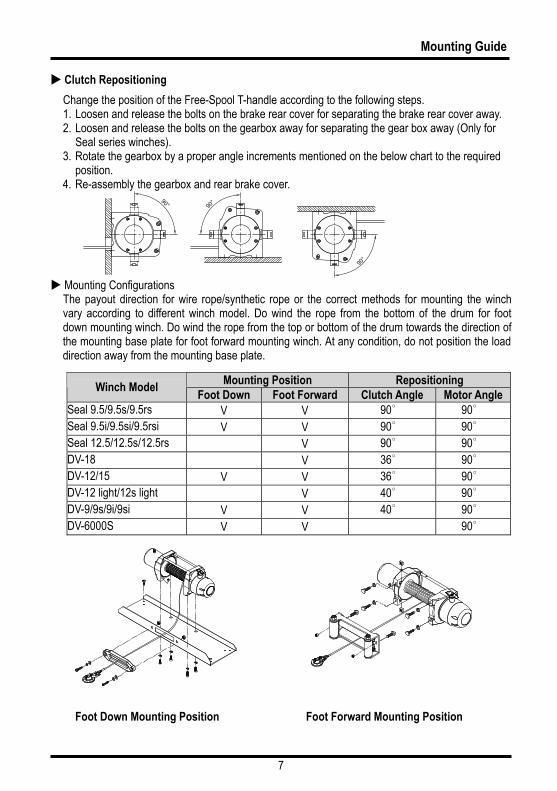
Clutch Repositioning
Change the position of the Free-Spool T-handle according to the following steps. 1. Loosen and release the bolts on the brake rear cover for separating the brake rear cover away. 2. Loosen and release the bolts on the gearbox away for separating the gear box away (Only for
Seal series winches). 3. Rotate the gearbox by a proper angle increments mentioned on the below chart to the required
position. 4. Re-assembly the gearbox and rear brake cover.
Mounting Configurations The payout direction for wire rope/synthetic rope or the correct methods for mounting the winch vary according to different winch model. Do wind the rope from the bottom of the drum for foot down mounting winch. Do wind the rope from the top or bottom of the drum towards the direction of the mounting base plate for foot forward mounting winch. At any condition, do not position the load direction away from the mounting base plate.
Foot Down Mounting Position Foot Forward Mounting Position
Mounting Position Repositioning Winch Model
Foot Down Foot Forward Clutch Angle Motor Angle Seal 9.5/9.5s/9.5rs V V 90∘ 90∘ Seal 9.5i/9.5si/9.5rsi V V 90∘ 90∘ Seal 12.5/12.5s/12.5rs V 90∘ 90∘ DV-18 V 36∘ 90∘ DV-12/15 V V 36∘ 90∘ DV-12 light/12s light V 40∘ 90∘ DV-9/9s/9i/9si V V 40∘ 90∘ DV-6000S V V 90∘

Safety Requirements
8
In some cases, the operator of a winch may be required to have qualifications according to applicable laws and ordinances.
Check safety and environmental conditions prior to and during use.
Only use correctly rated wire/synthetic rope in construction, strength. Inspect for damage and/or defects before use.
Don’t use an unsuitable hook and snatch block for rope.
The operator must remain with the winch during operation.
The winch duty rating is S3 (intermittent-periodic).
Do not use the winch as a lifting device or a hoist for vertical lifting and moving people.
Ensure that the winch is connected to the correct voltage. 12/24 VDC only.
Do not exceed maximum line pull ratings. Shock load must not exceed these ratings.
Keep hands clear of rope and fairlead opening.
Pull from an angle below 15° in the horizontal plane to straighten up the vehicle or load.
Always use leather gloves when handling the wire/synthetic rope.
When winching, always use a recovery damper. Place over the wire/synthetic rope in the middle third of its length.
A rope should be replaced if it shows signs of excessive wear, broken strands, corrosion for wire rope and excessive abrasion, broken strands, fused and melted fiber for synthetic rope.
If the winch fails to pull a load under normal conditions, stop the operation, otherwise motor damage may occur. The thermal indicator LEDs in the control box or remote switch will indicate RED as a warning.
Check that the clutch T-handle is in the “Engaged” position during and after use.
Remove the switch from the winch when not in use.
Do not wrap the wire/synthetic rope around the load and back onto itself. Always use a tree truck strap.
Keep hands and clothes away from the winch, rope, and roller/hawse fairlead.
Never unplug the remote control when winching a load.
To avoid insufficient power when winching a load, the vehicle should be running and in neutral.
If noise or vibration occurs when running, stop the winch immediately and return it for repair.
The rope shall be wound in according to drum rotation sticker or refer to owners manual.

Winching Principles
9
Calculating Fleet Angle
To obtain the best wire/synthetic rope service, the direction of pull will be on a horizontal within ±15 degrees and perpendicular to be centerline of the winch drum within ±5 degrees. If the fleet angle is bigger than the recommended angles, a good spooling cannot be obtained as the rope will spoon onto one side of the rope drum and possible damage to the rope or winch.
Load Rating
Load and speed varies according to how much wire/synthetic rope is on the drum. The first layer of rope on the drum delivers the slowest speed and the maximum load. A full drum delivers the maximum speed and the minimum load. For this reason, all automotive winches are rated at their first layer capacities.
Required Pulling Force
You need a winch powerful enough to overcome the weight of your vehicle with the added resistance caused by the obstacle, moving water, mud, snow, sand or on a steep hill.
As a general guide, you need a winch with a maximum line pull of at least 1.5 times greater than the gross vehicle weight.
There are three factors listed that influence the line pull effect required to recover the vehicle. The values and calculations in this section are approximate and are for reference only.
a). Gross vehicle weight
b). Type of the surface to be traversed
c). Gradient to overcome
In recovery and loading the winch is used to pull something, the required pulling force (RPF) can be calculated according to the formula:
RPF = (Wt X S) + (Wt X G) Where: Wt = The gross vehicle weight
S = The type of the surface to be traversed G = The gradient to overcome
Surface Type Surface Drag (S) Gradient Angle (θ) Gradient (G)
Metal 0.15 5% 3° 0.06
Sand 0.18 10% 6° 0.11
Gravel 0.20 20% 11° 0.2
Soft Sand 0.22 30% 17° 0.3
Mud 0.32 50% 26° 0.44
Marsh 0.52 70% 35° 0.58
Clay 0.52 100% 45° 0.71
Top layer (Max. speed Min. load)
Half layer (Med. speed Med. load)
First layer (Min. speed Max. load)
Flange of drum

Winching Principles
10
For example, if a vehicle weighing 3,000 kg is winched up an incline by 100% on the marsh road, the above formula would be used as follows:
Where Wt: 3,000 kg, S: 0.52 G: 0.71
RPF = (Wt X S) + (Wt X G)
= (3,000 kg X 0.52) + (3,000 kg X 0.71)
= 1,560 kg + 2,130 kg
= 3,690 kg of effect required to recover the vehicle.
Securing Anchor Point
When choosing an anchor point, select a safe and firm point such as a tree, stump or rocks. If using a winch to retrieve another vehicle, the rescue vehicle is considered the anchor point and should be made secure.
The anchor point must be strong enough to hold the gross weight of the vehicle and be positioned to keep the fleet angle between the centre of the anchor point and the wire/synthetic rope maintained less than 15°. Always use a tree trunk protector strap to prevent ring barking the tree and damaged to the wire/synthetic rope.
Winching V.S. Hoisting. A pulling winch should not be used for lifting.
Please refer to our website to view our full range of lifting winches.
A gradient of 10% is a rise of one meter in ten meters (High / Distance)
Slope High
Distance

Accessories
11
Roller Fairlead
The use of 4 ways roller fairlead can eliminate the contacting friction because the fairlead rollers contact with the wire rope. But the fairlead does not insure the wire rope will wind onto the drum in an orderly manner. The proper fleet angle within 15° must be maintained for the wire rope to wind onto the drum in an orderly manner. If the proper fleet angle is not maintained, it can result in damage to the winch and wire rope.
Hawse Fairlead
The basic hawse fairlead is designed to guide the synthetic rope to and from the winch drum. Do not use cast steel hawse fairleads as they have sharp edges and they do not have enough radius for the rope to bend over.
Recovery Damper
A recovery damper is a safety device designed to help eliminated the possibility of injury or property damage in the event of a wire/synthetic rope failure. Place in the middle third of a live rope. The damper can help absorb the energy in the rope and reduce the likelihood of injury or damage.
Snatch Block
An important aid to successful winching is the use of snatch block, which can be used to increase the pulling power of a winch or change the direction of a pull.
A winch double lined with a snatch block creates a mechanical leverage cutting the effort required by nearly half.
The double line pull shows self recovery using a snatch block attached to an anchor point; the pull applied to the vehicle is almost twice as much as the line pull of the winch.
The use of one snatch block shows an indirect pull where the vehicle is limited due to unsuitable ground or obstruction. The pull on the load is the actual line pull of the winch. If more than one snatch block is used, they must be located at least 100 cm (40�) apart.
Fleet angle
Fleet angle

Winching Procedures
12
Preparation before Winching
1). Connect the remote control
Always disconnect the remote control when not in use. Always have the remote control kept free from winch, wire/synthetic rope and roller/hawse fairlead.
2
2). Disengage clutch function
Lift the clutch T-handle up and turn it at 90° counter-clockwise rotation to the “Disengaged” position, rope can now clutch off the drum.
3). Pull the wire/synthetic rope to the anchor point Wear leather gloves when handling wire/synthetic rope. Pull out enough rope to reach the anchor point. Be careful to keep the rope under tension.
4). Engage clutch function
To engage, lift the clutch T-handle up and turn it at 90° clockwise rotation to the “Engaged” position. Never engage the clutch while the drum is rotating.
Winching Operation
1). Check the wire/synthetic rope Before winching, make sure the rope is wound on the drum evenly. If there is a mixed winding, it is essential to rewind it evenly.
2). Lay a recovery damper over the rope near the hook end. If a wire/synthetic rope failure occurs, the damper can prevent the rope from whipping.

Winching Procedures
13
3). Secure anchor point It is very important that an anchor point is strong enough to hold the load while winching. Do not wrap the rope around the load and back onto itself. Always use a strap to ensure that the wire/synthetic rope does not fray or kink.
PRND21
4). Setting the vehicle engine The recovery vehicle engine should be running to provide maximum power to the winch. The transmission shall be set in neutral, hand brake applied ad wheel chocked or vehicle anchored to prevent the vehicle from moving.
5). Attach shackle and hook Use a shackle to lock both ends of tree trunk protector, and then attach to the wire/synthe tic rope hoo k.
6). Begin winching Keep force on the rope to ensure it winds onto the drum evenly. Release hand brake and continue pulling until the vehicle is recovered.
7). Secure vehicle Once the vehicle is secured, wind the rope back onto the drum evenly and secure the hook firmly.
8). Disconnect remote control Take remote control out of the socket and store it in a safe and dry place.

Winching Procedures
14
Precaution while winching
Make sure the rope is wound on the drum evenly. A tightly spiraled pig-tailed rope will damage the rope, shorten its life.
Always keep clear of winch, rope, hook, and roller/hawse fairlead during winching.
Keep winching area clear. Do not allow people to remain in the area while winching.
Never guide a wire/synthetic rope onto the drum with your hand, use a hand saver strap.
Avoid remote control cord from touching the wire/synthetic rope.
A winching operation requires extra consumption of battery power, so always keep your battery set in a good condition.

Maintenance
15
Wire Rope Replacement
Do not wind out past the red paint section of the rope to secure the anchorage of the rope on the drum. 1). Disengage the clutch T-handle.
2). Spool the entire rope, and then remove it from the drum.
3). Place the replacement rope through the roller fairlead opening, pass below the drum and insert it into the hole on the drum core. Tighten the set-screw downwards to secure the wire rope.
4).A minimum of five (5) wraps of rope around the drum is necessary to support the rated load
Synthetic Rope Replacement
Do not wind out past the red paint section of the rope to secure the anchorage of the rope on the drum. 1). Disengage the clutch T-handle, remove existing rope and replace hawse if necessary.
2). Remove the set-screw on the drum and spool out the rope from the drum.
3). Cut the lateral side of the end by 45° and apply 2-3 wraps of electrical tape to hold cut strands in place
4). Thread rope through a hawse fairlead and under the drum, insert the rope through the hole on the drum with 15 – 20 cm / 6” – 8”.
5). Place rope across the drum and tape the end down to hold it in place. Lightly tighten the set-screw to squeeze the rope, do not over tighten.
6). A minimum of ten (10) wraps of rope around the drum is necessary to support the rated load
Tape
(Engage) (Disengage)

Maintenance
16
Tip for prolonging the life of Synthetic rope 1. Regular maintenance and periodically check the rope for damage or wear 2. Since too much abrasion can damage or weaken your synthetic rope, protect your rope from
rubbing against sharp objects or edge 3. An aluminum hawse fairlead is highly recommended since it has no sharp edges and resists
damage more easily than a roller fairlead 4. Keeping your synthetic rope clean and dry. To clean it after a muddy ride, spool out the 5. rope, rinse it with a hose, and let it dry completely before re-spooling
Brake Adjustment
Under normal use, the brake mechanism will not require any adjustment. If the brake fails to hold a load, the brake disc may be worn and require replacement. When the brake wears to the point that the load begins to slip, the brake can be adjusted as follows:
1). Loosen the bolt on the brake cover and take out the retaining rings
2). Insert spacers/washers to maintain the brake spacer between to be 2.2 ± 0.25 mm
3). Make sure to keep the clutch base plate is rotated counter-clockwise by 150 – 180 degree
Lubrication
All moving parts in the winch are permanently lubricated at the time of assembly. Under normal conditions factory lubrication will suffice. If re-lubrication of gear box is necessary after repair or disassembly use Shell EP2 or equivalent grease with enough quantity. Clutch T-handle lubricates regularly with light oil. It is not allowed to have brake assembly lubricated.

Maintenance
17
FEDERAL COMMUNICATIONS COMMISSION INTERFERENCE STATEMENT This equipment has been tested and found to comply with the limits for a Class B digital device, pursuant to part 15 of the FCC Rules. These limits are designed to provide reasonable protection against harmful interference in a residential installation. This equipment generates uses and can radiate radio frequency energy and, if not installed and used in accordance with the instructions, may cause harmful interference to radio communications. However, there is no guarantee that interference will not occur in a particular installation. If this equipment does cause harmful interference to radio or television reception, which can be determined by turning the equipment off and on, the user is encouraged to try to correct the interference by one or more of the following measures: - Reorient or relocate the receiving antenna. - Increase the separation between the equipment and receiver. - Connect the equipment into an outlet on a circuit different from that to which the receiver is
connected. - Consult the dealer or an experienced radio / TV technician for help.
CE Mark Warning • This is a Class B product, in a domestic environment, this product may cause radio
interference, in which case the user may be required to take adequate measures.
FCC and Industry Canada (IC) Warning: • This device complies with Part 15 of the FCC Rules. Operation is subject to the following two
conditions: (1) This device may not cause harmful interference, and (2) this device must accept any interference received, including interference that may cause undesired operation.
CAUTION: Any changes or modifications not expressly approved by the grantee of this device could void the user's authority to operate the equipment.

Maintenance
18
Maintenance Schedule
Classification of check
Periodical Daily
Monthly Quarterly
Item Checking method Checking reference
Installation Mounting bolts & alignment
Bolt tension & wear Existence of abnormalities
Working Manual Reasonable actuation
Wearing in contact points Visual Free of wear or damage
Remote control
LED lights red Visual LED light green
Broken strands Visual, i
Less than 10%
Decrease in rope diameter
Visual, measuring
7% of nominal diameter max
Fastening condition of end Visual Existence of abnormalities
Wire rope
Deforming or corrosion Visual Existence of abnormalities
Broken strands Visual, measuring
Two or more adjacent strands are cut
Decrease in rope diameter
Visual, measuring
25% of nominal diameter max
Fused or melted fibers Visual Existence of abnormalities
Synthetic rope
Fastening condition of end Visual Existence of abnormalities
Clutch assembly
Damaged clutch assembly
Visual evidence of wear Free of wear or damage
Motor Staining, damage Visual evidence of wear Existence of abnormalities
Wearing of brake disc
Visual evidence of wear Free of wear or damage
Brake
Performance Visual Reasonable actuation
Gear Damage, wearing Visual evidence of wear Free of wear or damage

Trouble Shooting
19
If the winch fails to operate after several attempt, or if there is any fault whilst operation:
Symptom Possible Cause Remedy Cut circuit Check battery lead Weak battery Recharge or replace battery, 650CCA Damaged over-load protector(option) Replace over-load protector(option) Bad connection of wiring Reconnect tightly Damaged contactor Replace contactor Cut circuit on switch Replace switch Damaged motor or carbon brush. Replace motor or carbon brush
Winch will not
operate
Poor or lost connections to motor Replace wiring or tighten it Broken wiring or bad connections Reconnect or replace wiring Damaged or stuck contactor Replace contactor Motor runs in one
direction. Switch inoperative Replace switch Clutch does not disengage Replace clutch Damaged 1st shaft Replace 1st shaft Damaged brake cam and disc Replace brake cam and disc
Drum will not clutch.
Damaged output shaft Replace output shaft The gear train is mechanically binding up
Check to insure the winch is mounted on a flat, rigid surface
Damaged brake cam and disc Replace brake cam and disc Damaged gear box Replace gear box Broken retaining ring Replace retaining ring Oil leakage into brake cavity Repair and clean oil leakage
No brake
Damaged or inoperative spiral spring Replace and position spiral spring Worn brake disc or loose brake spacer
Replace brake disc or adjust brake spacer according to brake adjustment procedures Brake distance is
too long Oil leakage into brake cavity Repair and clean oil leakage Too much brake disc powder in the brake hub Clean brake hub
Over tensioned spiral spring Adjust tension on spiral spring Brake will be locked Stuck between brake disc and gear
box Replace with new brake assembly
Hit by certain exterior force Replace the damaged components Damaged gear train Replace the damaged components
Damaged gear
box Over load operation Stop the winch operation and reduce the load
Long period of operation Allow to cool Damaged motor Replace or repair motor Motor runs
extremely hot Damaged or inoperative brake Replace or repair brake LED lights red in the remote switch Overheating of the motor Stop the winch operation and cool the
motor

20
Automotive Winch Limited Lifetime Warranty for Mechanical Components Limited One (1) Year Warranty for Electrical Components
WARRANTY Comeup Industries Inc. (COMEUP) warrants to the original purchaser that the mechanical
components of the COMEUP Automotive Winch will be free of defects in material and workmanship for the lifetime of the winch and the electrical components will be free of defects in material and workmanship for a period of one (1) year from the original date of purchase. All COMEUP mounting kits and other accessories carry a one (1) year limited warranty against defects in material workmanship.
This warranty applies only to the original purchaser of the winch. To obtain any warranty service, the purchaser under this Limited Warranty is requested to advise COMEUP or its authorized distributors on any claim. The purchaser must provide a copy of the purchase receipt bearing the winch serial number, date of purchase, owners name, email or Tel & Fax, address and purchaser vehicle details. Any products that COMEUP determines to be accountable for defective will be repaired or replaced or refund at COMEUP sole discretion without charge to buyer upon buyer’s compliance with these procedures. In the event of repair or replace, purchaser must send the defective winch or part, with freight prepaid, to COMEUP or its authorized distributor. And COMEUP will send the serviced product back to purchaser on COMEUP’s cost. This warranty does not cover the removal or reinstallation of the winch.
COMEUP takes the responsibility for COMEUP winch parts and components to be free from defects in materials and workmanship, but the following portions are hereby excluded and disclaimed. COMEUP or its authorized distributors may make reasonable charges for parts and labour for repairs or resumption in the following portions not covered by this limited warranty. (1). All warranties of wire rope and synthetic rope assemblies after initial use (2). All warranties of fitness for a particular purpose (3). All warranties of the product’s finish (4). All warranties of merchantability
The limited warranty does not cover any failure that results from improper installation/operation, third party part substitution, purchaser’s alteration or modification on COMEUP winch. This warranty is void when COMEUP serial number plate is removed or defaced.
COMEUP’s liability to the purchaser under the winch purchases for any loss or damage howsoever and whatsoever arising shall not exceed the price of the initial winch purchase receipt. COMEUP shall not in any event be liable to the purchaser for any consequential and/or indirect loss or damage whether for loss or for profit or otherwise, costs, expenses or other claims for consequential compensation whatsoever and whether caused by negligence of COMEUP employees, distributors and their employees or otherwise. COMEUP reserves the right to change product design without notice. In situations in which COMEUP has changed a product design, COMEUP shall have no obligation to upgrade or otherwise modify previously manufactured products.
