automotive vehicles – approval of devices for …6~2011~5~34~15~pm~ais...ais-001 (part 1) (rev.1)...
TRANSCRIPT

AIS-001 (Part 1) (Rev.1) : 2011
I
AUTOMOTIVE INDUSTRY STANDARD
Automotive Vehicles – Approval of Devices for Indirect Vision Intended for use on M, N Category and L Category with Bodywork Vehicles – Specification
(Revision 1)
PRINTED BY THE AUTOMOTIVE RESEARCH ASSOCIATION OF INDIA
P.B. NO. 832, PUNE 411 004
ON BEHALF OF AUTOMOTIVE INDUSTRY STANDARDS COMMITTEE
UNDER
CENTRAL MOTOR VEHICLE RULES – TECHNICAL STANDING COMMITTEE
SET-UP BY MINISTRY OF ROAD TRANSPORT & HIGHWAYS
(DEPARTMENT OF ROAD TRANSPORT & HIGHWAYS) GOVERNMENT OF INDIA
May 2011

AIS-001 (Part 1) (Rev.1) : 2011
II
Status chart of the standard to be used by the purchaser for updating the record
Sr. No.
Corrigenda. Amendment Revision Date Remark Misc.
General remarks :

AIS-001 (Part 1) (Rev.1) : 2011
III
INTRODUCTION
0.0 The Government of India felt the need for a permanent agency to expedite the publication of standards and development of test facilities in parallel when the work on the preparation of the standards is going on, as the development of improved safety critical parts can be undertaken only after the publication of the standard and commissioning of test facilities. To this end, the erstwhile Ministry of Surface Transport (MOST) has constituted a permanent Automotive Industry Standards Committee (AISC) vide order No. RT-11028/11/97-MVL dated September 15, 1997. The standards prepared by AISC will be approved by the permanent CMVR Technical Standing Committee (CTSC). After approval, the Automotive Research Association of India, (ARAI), Pune, being the Secretariat of the AIS Committee, has published this standard. For better dissemination of this information ARAI may publish this document on their web site.
0.1 Accordingly AIS-001 covering mandatory requirements regarding performance of rear view mirrors devices has been published in 2001 and has been implemented thereafter in 2003.
0.2 With technological developments in automotive vehicles rear view mirrors, AIS-001 was taken up for revision and now is prepared in two parts. This part covers the requirements for approval of devices for indirect vision for use on M, N, category and L category vehicles with bodywork vehicles- specification.
0.3
This part is based on the following ECE Regulation
ECE R 46, Rev. 3, Supplement 4 to the 02 series of amendment (Date of entry into force 22 July 2009).
Uniform Provisions Concerning the Approval of Devices for Indirect Vision and of Motor Vehicles with regard to the Installation of these Devices
0.4
While preparing this standard attempts have been made to align with the above ECE regulation. However, certain changes were necessary in the Indian context.
0.5 The following standards contain provisions, which through reference in this text constitute provisions of the standard.
AIS-002 (Part 1) (Rev.1):2011
Automotive Vehicles – Devices for indirect Vision intended for use on L category with bodywork vehicles, M and N category -Installation requirements
AIS-037 Procedure for Type Approval and Establishing Conformity of Production for Safety Critical Components.
AIS-053 Automotive Vehicles – Types – Terminology

AIS-001 (Part 1) (Rev.1) : 2011
IV
IS 13942:1994 Automotive vehicles - External projections - Performance requirements
ISO 15008:2003 Road vehicles -- Ergonomic aspects of transport
information and control systems -- Specifications and compliance procedures for in-vehicle visual presentation
CIE publication 50 (45)
International Electronical Vocabulary, Group 45, Lighting
EN 12368: 8.4 Traffic Control Equipment – Signal heads.
0.6
The composition of AISC panel and AIS Committee responsible for preparation of this standard is given in Annex M and Annex N respectively.

AIS-001 (Part 1) (Rev.1) : 2011
V
Automotive Vehicles –Approval of Devices for Indirect Vision Intended for use on M, N Category and L Category
with Bodywork Vehicles – Specification
Para. No. Contents Page No.
1. Scope 1/35
2. Definitions 1/35
3. Application for approval 4/35
4. Markings 4/35
5. Approval 5/35
6. Requirements 5/35
7. Extension of type approval 14/35
8. Conformity of production 15/35
9. Penalties for non-conformity of production 15/35
10. to 20 Reserved 15/35
21. Transitional provisions 15/35
22.
Establishing compliance of “E”/“e” approved devices to this standards
16/35
23. Amendments to ECE regulations after the level described in 0.3 of introduction
17/35
List of Annexes:
Annex A Information to be submitted at the time of applying for type approval
18/35
Annex B Reserved 20/35
Annex C Reserved 20/35
Annex D Reserved 20/35
Annex E Reserved 20/35
Annex F Test method for determining reflectivity 21/35
Annex G Procedure for determining the Radius of Curvature "r" of the reflecting surface of a mirror.
28/35
Annex H Reserved 30/35
Annex J Reserved 30/35
Annex K Reserved 30/35
Annex L Criteria for extension of approval 31/35

AIS-001 (Part 1) (Rev.1) : 2011
1/35
Automotive Vehicles – Approval of Devices for Indirect Vision Intended for use on M, N Category and L Category with
Bodywork Vehicles – Specification
1. SCOPE
This standard applies to devices for indirect vision intended to be installed on motor vehicles of categories L category with bodywork at least partly enclosing the driver, M, N and A as defined in AIS-053.
Note: The permission to use rear view mirrors and indirect vision devices covered by this standard are governed by requirements specified by the standard for installation of requirements of that category of vehicles.
2. DEFINITIONS
For the purposes of this standard:
2.1. "Devices for indirect vision" means devices to observe the traffic area adjacent to the vehicle, which cannot be observed by direct vision. These may be conventional mirrors, camera-monitors or other devices able to present information about the indirect field of vision to the driver.
2.1.1 "Mirror" means any device, excluding devices such as periscopes, intended to give a clear view to the rear, side or front of the vehicle within the fields of vision defined in 15.2.4 of AIS-002(Part 1)(Rev. 1).
2.1.1.1. "Interior mirror" means a device as defined in 2.1, which is intended to be fitted in the passenger compartment of a vehicle.
2.1.1.2. "Exterior mirror" means a device as defined in 2.1, which is intended to be mounted on the external surface of a vehicle.
2.1.1.3. "Surveillance mirror" means a mirror other than the ones defined in 2.1.1. which is intended to be fitted to the inside or outside of the vehicle in order to provide fields of vision other than those specified in 15.2.4 of AIS-002(Part 1)(Rev. 1).
2.1.1.4. "Vision support system" means a system to enable the driver to detect and/or see objects in the area adjacent to the vehicle."
2.1.1.5. "r" means the average of the radii of curvature measured over the reflecting surface, in accordance with the method described in Annex G.
2.1.1.6. "The principal radii of curvature at one point on the reflecting surface (ri)" means the values obtained with the apparatus defined in Annex G measured on the arc of the reflecting surface passing through the centre of this surface parallel to the segment b, as defined in 6.1.2.1.2.1 and on the arc perpendicular to this segment.

AIS-001 (Part 1) (Rev.1) : 2011
2/35
2.1.1.7. The radius of curvature at one point on the reflecting surface (rp)" means the arithmetical average of the principal radii of curvature ri and r′i i.e.:
2ii
pr'rr
+ =
2.1.1.8. "Spherical surface" means a surface, which has a constant and equal radius in all directions
2.1.1.9. "Aspherical surface" means a surface, which has only in one plane a constant radius.
2.1.1.10. "Aspherical mirror" means a mirror composed of a spherical and an aspherical part, in which the transition of the reflecting surface from the spherical to the aspherical part has to be marked. The curvature of the main axis of the mirror is defined in the x/y coordinate system defined by the radius of the spherical primary calotte with:
322 )()( axkxRRy −+−−=
R: nominal radius in the spherical part k: constant for the change of curvature a: constant for the spherical size of the spherical primary calotte
2.1.1.11. "Centre of the reflecting surface" means the centre of the visible area
of the reflecting surface.
2.1.1.12. "The radius of curvature of the constituent parts of the mirror" means the radius "c" of the arc of the circle which most closely approximates to the curved form of the part in question.
2.1.1.13 "Class of mirror" means all devices having one or more common characteristics or functions. They are classified as follows:
Class I "Interior rear-view mirror", intended to give the field of vision defined in 15.2.4.1 of AIS-002 (Part 1)(Rev. 1)
Class II and III "Main exterior rear-view mirror", intended to give the fields of vision defined in 15.2.4.2 and 15.2.4.3 of AIS-002 ( Part 1)(Rev. 1)
Class IV "Wide-angle exterior mirror", intended to give the field of vision defined in 1 5.2.4.4 of AIS-002 (Part 1) (Rev. 1).
Class V "Close-proximity exterior mirror", intended to give the field of vision defined in 15.2.4.5 of AIS-002 (Part 1) ( Rev. 1)
Class VI "Front mirror", intended to give the field of vision defined in 15.2.4.6 of AIS-002 (Part 1) (Rev. 1).
Class VII Mirrors intended for L category vehicles with bodywork intended to give the field of vision defined in 15.2.4.7 of AIS-002(Part 1) (Rev. 1).

AIS-001 (Part 1) (Rev.1) : 2011
3/35
2.1.2. "Camera-monitor device for indirect vision" means a device as defined in 2.1, where the field of vision is obtained by means of a camera-monitor combination as defined in 2.1.2.1 and 2.1.2.2.
2.1.2.1. "Camera" means a device that renders an image of the outside world and then converts this image into a signal (e.g. video signal).
2.1.2.2. "Monitor" means a device that converts a signal into images that are rendered into the visual spectrum.
2.1.2.3. "Detection" means the ability to distinguish an object from its background/surroundings at certain distance.
2.1.2.4. "Luminance contrast” means the brightness ratio between an object and its immediate background/surrounding that allows the object to be distinguished from its background/surroundings.
2.1.2.5. "Resolution" means the smallest detail that is discerned with a perceptual system, i.e. perceived as separate from the larger whole. The resolution of the human eye is indicated as "visual acuity".
2.1.2.6. "Critical object" means a circular object with a diameter D0 = 0.8 m. (See note below)
Note: A system for indirect vision is intended to detect relevant road users. The relevancy of a road user is defined by his or her position and (potential) speed. More or less in proportion with the speed of the pedestrian-cyclist- moped driver, the dimensions of these road users increase as well. For detection purposes a moped driver (D = 0.8 m) at 40 m distance would be equal to a pedestrian (D = 0.5 m) at a distance of 25 m. Considering the speeds, the moped driver would be selected as the criterion for the detection size; for that reason an object with a size of 0.8 m shall be used for determining the detection performance.
2.1.2.7. "Critical perception" means the level of perception that the human eye is generally capable of achieving under various conditions. For traffic conditions the limiting value for a critical perception is eight arc-minutes of visual angle.
2.1.2.8. “Field of vision" means the section of the tri-dimensional space which is monitored with the help of a device for indirect vision. Unless otherwise stated, this is based on the view on ground level offered by a device and/or devices other than mirrors. This may be limited by the relevant detection distance corresponding to the critical object.
2.1.2.9. "Detection distance" means the distance measured at ground level from the viewing reference point to the extreme point at which a critical object is just perceived (the limiting value for a critical perception just barely achieved).
2.1.2.10. "Critical field of vision" means the area in which a critical object has to be detected by means of a device for indirect vision and that is defined by an angle and one or more detection distances.

AIS-001 (Part 1) (Rev.1) : 2011
4/35
2.1.2.11. "Viewing reference point" means the point linked to the vehicle to which the prescribed field of vision is related. This point is the projection on the ground of the intersection of a vertical plane passing through the driver's ocular points with a plane parallel to the median longitudinal plane of the vehicle situated 20 cm outside the vehicle.
2.1.2.12. "Visual spectrum" means light with a wavelength within the range of the perceptual limits of the human eyes: 380-780 nm.
2.1.2.13. "Surveillance camera-monitor-recording device" means a camera and either a monitor or recording equipment other than the camera-monitor device defined in 2.1.2. which can be fitted to the inside or outside of the vehicle in order to provide fields of vision other than those specified in 15.2.4. of AIS-002 (Part 1) (Rev. 1) or to provide a security system within or around the vehicle
2.1.3. "Other devices for indirect vision" means devices as defined in 2.1., where the field of vision is not obtained by means of a mirror or a camera-monitor type device for indirect vision.
2.1.4.
"Type of device for indirect vision" means devices that do not differ on the following essential characteristics:
• design of the device inclusive, if pertinent, the attachment to the bodywork;
• in case of mirrors the class, the shape, the dimensions and radius of curvature of the mirror's reflecting surface;
• in case of camera-monitor devices the detection distance and
the range of vision.
3. APPLICATION FOR APPROVAL
3.1 Information to be submitted at the time of applying for type approval of the indirect vision devices shall be as given in Annex A
3.2 Reserved.
3.3 For each type of device for indirect vision the application shall be accompanied by:
3.3.1 in case of mirrors, four samples: three for use in the tests and one to be retained by the laboratory for any further examination that might subsequently prove necessary. Additional specimens may be called for at the request of the testing agency.
3.3.2 in case of other devices for indirect vision: one sample of all the parts.
4. MARKINGS
4.1. The samples of devices for indirect vision submitted for approval shall bear the trade name or mark of the manufacturer; this marking shall be clearly legible and be indelible.

AIS-001 (Part 1) (Rev.1) : 2011
5/35
4.2 Every device shall possess a space large enough to accommodate the approval mark, which shall be legible when the device has been mounted on the vehicle; this space shall be shown on the sketches referred to in Annex A.
Note 1: The above condition is deemed to be complied with if the space for approval marking is on the portion which does not get housed in the vehicle at the time of installation or on a portion which can be seen by repositioning the mirror.
Note 2: On the prototype for type approval, the markings may be provided by suitable temporary methods and need not necessary be obtained from the tools used for series production.
5. APPROVAL
5.1. If the samples submitted for approval meet the requirements of 6. of this standard, approval of the pertinent type of device for indirect vision shall be granted.
5.2. The Approval number shall be as per AIS-037.
5.3. Reserved
5.4 Reserved
5.4.1. Reserved
5.4.2. Reserved
5.4.3 In addition to the approval mark (5.2), an additional symbol I or II or III or IV or V or VI, or VII specifying the class to which the type of mirror belongs or the symbol S in case of any device for indirect vision other than a mirror. The additional symbol shall be placed in any convenient position.
5.5. The approval mark and the additional symbol shall be clearly legible and be indelible.
5.6 Reserved
6. REQUIREMENTS
6.1 Mirrors
6.1.1 General specifications
6.1.1.1. All mirrors shall be adjustable.
6.1.1.2. The edge of the reflecting surface shall be enclosed in a protective housing (holder, etc.) which, on its perimeter, shall have a value 'c' greater than or equal to 2.5 mm at all points and in all directions.

AIS-001 (Part 1) (Rev.1) : 2011
6/35
If the reflecting surface projects beyond the protective housing, the
radius of curvature 'c' on the edge of the projecting part shall be not less than 2.5 mm and the reflecting surface shall return into the protective housing under a force of 50 N applied to the point of greatest projection, relative to the protective housing, in a horizontal direction, approximately parallel to the longitudinal median plane of the vehicle.
6.1.1.3. When the mirror is mounted on a plane surface, all parts, irrespective of the adjustment position of the device, including those parts remaining attached to the support after the test provided for in 6.1.3.2, which are in potential, static contact with a sphere either 165 mm in diameter in the case of an interior mirror or 100 mm in diameter in the case of an exterior mirror, shall have a radius of curvature 'c' of not less than 2.5 mm.
6.1.1.4 Edges of fixing holes or recesses of which the diameter or longest diagonal is less than 12 mm are exempt from the radius requirements of 6.1.1.3. provided that they are blunted.
6.1.1.5. The device for the attachment of mirrors to the vehicle shall be so designed that a cylinder with a 70 mm radius, (50 mm in the case of an L-category vehicle), having at its axis, or one of the axes, of pivot or rotation which ensures deflection of the mirror in the direction of impact concerned, passes through at least part of the surface to which the device is attached.
6.1.1.6. The parts of exterior mirrors referred to in 6.1.1.2. and 6.1.1.3. which are made of a material with a Shore A hardness not exceeding 60 are exempt from the relevant provisions.
6.1.1.7 In the case of those parts of interior mirrors which are made of a material with a Shore A hardness of less than 50 and which are mounted on a rigid support, the requirements of 6.1.1.2. and 6.1.1.3 shall only apply to the support.
6.1.2 Special specifications
6.1.2.1. Dimensions
6.1.2.1.1 Interior rear-view mirrors (Class I)
The dimensions of the reflecting surface shall be such that it is possible to inscribe thereon a rectangle one side of which is 40 mm and the other 'a' mm in length, where
r
10001
mm 150a+
×=1
and r is the radius of curvature.

AIS-001 (Part 1) (Rev.1) : 2011
7/35
6.1.2.1.2 Main exterior rear-view mirrors (Classes II and III)
6.1.2.1.2.1. The dimensions of the reflecting surface shall be such that it is possible to inscribe therein:
a rectangle 40 mm high the base length of which, measured in millimeters, has the value 'a';
a segment which is parallel to the height of the rectangle and the length of which, expressed in millimeters, has the value 'b'.
6.1.2.1.2.2 The minimum values of 'a' and 'b' are given in the table below:
Class of rear-view mirror a (mm) b (mm)
II r
1000 1
170
+
200
III r
1000 1
130
+
70
6.1.2.1.3. "Wide-angle" exterior mirrors (Class IV)
The contours of the reflecting surface shall be of simple geometric
form and its dimensions such that it provides, if necessary in conjunction with a Class II exterior mirror, the field of vision specified in 15.2.4.4. of AIS-002 (Part 1) (Rev. 1).
6.1.2.1.4. "Close-proximity" exterior mirrors (Class V)
The contours of the reflecting surface shall be of simple geometric form and its dimensions such that the mirror provides the field of vision specified in 15.2.4.5. of AIS-002 (Part 1) (Rev. 1).
6.1.2.1.5. Front mirrors (Class VI)
The contours of the reflecting surface shall be of simple geometric form and its dimensions such that the mirror provides the field of vision specified in 15.2.4.6. of AIS-002 (Part 1) (Rev. 1).
Note : Conditions given in 6.1.2.1.3, 6.1.2.1.4 and 6.1.2.1.5 are for general guidelines and need not be verified at the time of type approval of the mirror
6.1.2.1.6. Mirrors for Category L vehicles with bodywork (Class VII)
6.1.2.1.6.1 'Main' exterior mirrors (Class VII)
The minimum dimensions of the reflecting surface shall be as per 7.1 of Part 2 of this standard.
AIS-001 (Part 1) (Rev.1) : 2011
8/35
6.1.2.2 Reflecting surface and coefficients of reflection
6.1.2.2.1 The reflecting surface of a mirror shall be either flat or spherically convex. Exterior mirrors may be equipped with an additional aspherical part provided that the main mirror fulfils the requirements of the indirect field of vision.
6.1.2.2.2 Differences between the radii of curvature of mirrors
6.1.2.2.2.1 The difference between ri or r'i, and rp at each reference point shall not exceed 0.15 r
6.1.2.2.2.2 The difference between any of the radii of curvature (rp1, rp2, and rp3) and r shall not exceed 0.15 r.
6.1.2.2.2.3 When r is not less than 3,000 mm, the value of 0.15 r quoted in 6.1.2.2.2.1. and 6.1.2.2.2.2. is replaced by 0.25 r.
6.1.2.2.3 Requirements for aspherical parts of mirrors
6.1.2.2.3.1 Aspherical mirrors shall be of sufficient size and shape to provide useful information to the driver. This normally means a minimum width of 30 mm at some point.
6.1.2.2.3.2 The radius of curvature ri of the aspherical part shall not be less than 150 mm.
6.1.2.2.4 Value of 'r' for spherical mirrors shall not be less than:
6.1.2.2.4.1 1,200 mm for interior rear-view mirrors (Class I);
6.1.2.2.4.2 1,200 mm for Class II and III main exterior rear-view mirrors;
6.1.2.2.4.3 300 mm for "wide-angle" exterior mirrors (Class IV) and "close-proximity" exterior mirrors (Class V);
6.1.2.2.4.4 200 mm for front mirrors (Class VI).
6.1.2.2.4.5 1000 mm or more than 1500 mm in the case of Class VII mirrors
6.1.2.2.5 The value of the normal coefficient of reflection, as determined according to the method described in Annex F, shall be not less than 40 per cent.
In the case of reflecting surfaces with a changeable degree of reflection, the "day" position shall allow the colours of the signals used for road traffic to be recognized. The value of the normal coefficient of reflection in the "night" position shall be not less than 4 per cent.
6.1.2.2.6.
The reflecting surface shall retain the characteristics laid down in 6.1.2.2.5. in spite of prolonged exposure to adverse weather conditions in normal use.
Note : 6.1.2.2.6 is general clause and no specific tests are required for verifying compliance to this clause.
AIS-001 (Part 1) (Rev.1) : 2011
9/35
6.1.3. Test
6.1.3.1. Mirrors in Classes I to VI and Class VII (having fitments identical to Class III) shall be subjected to the tests described in 6.1.3.2.1 and 6.1.3.2.2. Class VII mirrors with a stem, shall be subjected to the tests described in 6.1.3.2.3.
6.1.3.1.1. The test provided for in 6.1.3.2. shall not be required in the case of any exterior mirror of which no part is less than 2 m from the ground, regardless of the adjustment position, when the vehicle is under a load corresponding to its maximum technically permissible mass.
This derogation also applies to the attachments of mirrors (attachment plates, arms, swivel joints, etc.) which are situated less than 2 m from the ground and which do not project beyond the overall width of the vehicle, measured in the transverse plane passing through the lowest mirror attachments or any other point forward of this plane if this configuration produces a greater overall width.
In such cases, a description specifying that the mirror shall be mounted so as to conform to the above-mentioned conditions for the positioning of its attachments on the vehicle must be provided.
Where advantage is taken of this derogation, the arm shall be indelibly marked with the symbol
2 m ∆
and the type-approval report shall be endorsed to this effect.
6.1.3.2. Impact test
The test according to this paragraph is not to be carried out for devices integrated in the bodywork of the vehicle and providing a frontal deflecting area of an angle not more than 45° measured in relation to the longitudinal median plane of the vehicle, or devices not protruding more than 100 mm measured beyond the circumscribing bodywork of the vehicle according to IS: 13942.
Note: If this test is not carried out, it shall be mentioned in the test report.
6.1.3.2.1. Description of the test rig
6.1.3.2.1.1.
The test rig consists of a pendulum capable of swinging about two horizontal axes at right angles to each other, one of which is perpendicular to the plane containing the "release" trajectory of the pendulum.
The end of the pendulum comprises a hammer formed by a rigid sphere with a diameter of 165 ± 1 mm having a 5 mm thick rubber covering of Shore A hardness 50.
A device is provided which permits determination of the maximum angle assumed by the arm in the plane of release.

AIS-001 (Part 1) (Rev.1) : 2011
10/35
A support firmly fixed to the structure of the pendulum serves to hold the specimens in compliance with the impact requirements specified in 6.1.3.2.2.6.
Figure 1 below gives the dimensions (in mm) of the test rig and the special design specifications:
Figure 1
(See 6.1.3.2.1.1.)
6.1.3.2.1.2.
The centre of percussion of the pendulum coincides with the centre of the sphere, which forms the hammer. It is at a distance l from the axis of oscillation in the release plane, which is equal to 1 m ± 5 mm. The reduced mass of the pendulum is mo = 6.8 ± 0.05 kilograms. The relationship of mo to the total mass m of the pendulum and to the distance d between the centre of gravity of the pendulum and its axis of rotation is expressed in the equation:
ldmmo ×=
6.1.3.2.2 Description of the test
6.1.3.2.2.1 The procedure used to clamp the mirror to the support shall be that recommended by the manufacturer of the device or, where appropriate, by the vehicle manufacturer.
6.1.3.2.2.2 Positioning of the mirror for the test:
6.1.3.2.2.2.1 Mirrors shall be positioned on the pendulum impact rig in such a way that the axes which are horizontal and vertical when the mirror is installed on a vehicle in accordance with the applicant's mounting instructions are in a similar position;

AIS-001 (Part 1) (Rev.1) : 2011
11/35
6.1.3.2.2.2.2 When a mirror is adjustable with respect to the base, the test position shall be that in which any pivoting device is least likely to operate, within the limits of adjustment provided by the applicant;
6.1.3.2.2.2.3 When the mirror has a device for adjusting its distance from the base, the device shall be set in the position in which the distance between the housing and the base is shortest
6.1.3.2.2.2.4 When the reflecting surface is mobile in the housing, it shall be so adjusted that the upper corner, which is furthest from the vehicle, is in the position of greatest projection relative to the housing.
6.1.3.2.2.3 Except in the case of test 2 for interior mirrors (see 6.1.3.2.2.6.1.), when the pendulum is in a vertical position the horizontal and longitudinal vertical planes passing through the centre of the hammer shall pass through the centre of the reflecting surface as defined in 2.1.1.11. The longitudinal direction of oscillation of the pendulum shall be parallel to the longitudinal median plane of the vehicle.
6.1.3.2.2.4 When, under the conditions governing adjustment laid down in 6.1.3.2.2.1. and 6.1.3.2.2.2. parts of the mirror limit the return of the hammer, the point of impact shall be displaced in a direction perpendicular to the axis of rotation or pivoting in question.
The displacement shall be no greater than is strictly necessary for the execution of the test; it shall be limited in such a way that: a) either the sphere delimiting the hammer remains at least
tangential to the cylinder as defined in 6.1.1.5.; b) or the point of contact with the hammer is located at least
10 mm from the periphery of the reflecting surface.
6.1.3.2.2.5.
The test consists in allowing the hammer to fall from a height corresponding to a pendulum angle of 60° from the vertical so that the hammer strikes the mirror at the moment when the pendulum reaches the vertical position.
6.1.3.2.2.6. The mirrors are subjected to impact under the following different conditions:
6.1.3.2.2.6.1. Interior mirrors
a) Test 1: The points of impact shall be as defined in 6.1.3.2.2.3. The impact shall be such that the hammer strikes the mirror on the reflecting surface side.
b) Test 2: Point of impact on the edge of the protective housing,
such that the impact produced makes an angle of 45° with the plane of the reflecting surface and is situated in the horizontal plane passing through the centre of that surface. The impact shall occur on the reflecting surface side.

AIS-001 (Part 1) (Rev.1) : 2011
12/35
6.1.3.2.2.6.2. Exterior mirrors
a) Test 1: The point of impact shall be as defined in 6.1.3.2.2.3. or 6.1.3.2.2.4. The impact shall be such that the hammer strikes the mirror on the reflecting surface side.
b) Test 2: The point of impact shall be as defined in 6.1.3.2.2.3.
or 6.1.3.2.2.4. The impact shall be such that the hammer strikes the mirror on the side opposite to the reflecting surface.
6.1.3.2.2.6.2.1. Where Class II or III rear-view mirrors are fixed to the same
mounting as Class IV rear-view mirrors, the above-mentioned tests shall be executed on the lower mirror. Nevertheless, the testing agency may repeat one or both of these tests on the upper mirror if this is less than 2 m from the ground.
6.1.3.2.3 Bending test on the protective housing attached to the stem (Class VII)
6.1.3.2.3.1 Description of test
The test shall be carried out as per 8.3 of Part 2 of this standard
6.1.3.3 Results of the tests
6.1.3.3.1 In the tests described in 6.1.3.2., the pendulum shall continue to swing after impact in such a way that the projection of the position assumed by the arm on the plane of release makes an angle of at least 20° with the vertical. The accuracy of measurement of the angle shall be within ± 1°.
6.1.3.3.1.1 This requirement is not applicable to mirrors stuck to the windscreen, in respect of which the requirement stipulated in 6.1.3.3.2. shall apply after the test.
6.1.3.3.1.2 The required angle to the vertical is reduced from 20° to 10° for all Class II and Class IV rear-view mirrors and for Class III rear-view mirrors which are attached to the same mounting as Class IV mirrors.
6.1.3.3.2 Should the mounting of the mirror break during the tests described in 6.1.3.2. for mirrors stuck to the windscreen, the part remaining shall not project beyond the base by more than 10 mm and the configuration remaining after the test shall satisfy the conditions laid down in 6.1.1.3.
6.1.3.3.3 The reflecting surface shall not break during the tests described in 6.1.3.2. However, breakage of the reflecting surface will be allowed if one of the following conditions is fulfilled:
6.1.3.3.3.1. the fragments of glass still adhere to the back of the housing or to a surface firmly attached to the housing; partial separation of the glass from its backing is admissible provided that this does not exceed 2.5 mm on either side of the cracks. It is permissible for small splinters to become detached from the surface of the glass at the point of impact.

AIS-001 (Part 1) (Rev.1) : 2011
13/35
6.1.3.3.3.2 the reflecting surface is made of safety glass.
6.2. Devices for indirect vision other than mirrors
6.2.1 General requirements
6.2.1.1 If adjustment by the user is needed, the device for indirect vision shall be adjustable without the use of tools.
6.2.1.2 If a device for indirect vision is able to only render the total prescribed field of vision by scanning the field of vision, the total process of scanning, rendering and reset to its initial position together shall not take more than 2 seconds.
6.2.2 Camera-monitor devices for indirect vision
6.2.2.1 General requirements
6.2.2.1.1 When the camera-monitor device for indirect vision is mounted on a plane surface, all parts, irrespective of the adjustment position of the device which are in potential, static contact with a sphere either 165 mm in diameter in the case of a monitor or 100 mm in diameter in the case of a camera, shall have a radius of curvature "c" of not less than 2.5 mm.
6.2.2.1.2 Edges of fixing holes or recesses of which the diameter or longest diagonal is less than 12 mm are exempt from the radius requirements of 6.2.2.1.1. provided that they are blunted.
6.2.2.1.3 For parts of the camera and the monitor which are made of a material with a Shore A hardness of less than 60 and which are mounted on a rigid support, the requirements of 6.2.2.1.1. shall only apply to the support.
6.2.2.2 Functional requirements
6.2.2.2.1 The camera should function well under low sunlight conditions. The camera shall provide a luminance contrast of at least 1:3 under low sun condition in a region outside the part of the image where the light source is reproduced (condition as defined in EN 12368: 8.4). The light source shall illuminate the camera with 40,000 lx. The angle between the normal of the sensor plane and the line connecting the midpoint of the sensor and the light source shall be 10°.
6.2.2.2.2 The monitor shall render a minimum contrast under various light conditions as specified by ISO 15008:2003.
6.2.2.2.3 It shall be possible to adjust the average luminance of the monitor either manually or automatically to the ambient conditions.
6.2.2.2.4 The measurements for the luminance contrast shall be carried out according to ISO 15008:2003.

AIS-001 (Part 1) (Rev.1) : 2011
14/35
6.2.3. Other devices for indirect vision
It has to be proved that the device meets the following requirements:
6.2.3.1 The device shall perceive the visual spectrum and shall always render this image without the need for interpretation into the visual spectrum.
6.2.3.2 The functionality shall be guaranteed under the circumstances of use in which the system shall be put into service. Depending on the technology used in obtaining images and presenting them 6.2.2.2. shall be entirely or partly applicable. In other cases this may be achieved by establishing and demonstrating by means of system sensitivity analogous to 6.2.2.2. that a function is ensured that is comparable to or better than what is required for and by demonstrating that a functionality is guaranteed that is equivalent or better than that required for mirror- or camera-monitor type devices for indirect vision.
7 EXTENSION OF TYPE APPROVAL
7.1 Every modification pertaining to the information, even if the changes are not technical in nature declared in accordance with 3.2 shall be intimated by the manufacturer to the testing agency. If the changes are in parameters not related to the provisions, no further action need be taken. If the changes are in parameters related to the provisions, the Testing Agency, which has issued the certificate of compliance, shall then consider, whether,
7.1.1 the device with the changed specifications still complies with provisions, or
7.1.2 Any further verification is required to establish compliance.
7.2 For considering whether testing is required or not, guidelines given in para 7.5 (Criteria for Extension of Approval) shall be used.
7.3 In case of 7.1.2, tests for only those parameters which are affected by the modifications need be carried out
7.4 In case of fulfilment of criterion of para 7.1.1 or after results of further verification as per para of 7.1.2 are satisfactory, the approval of compliance shall be extended for the changes carried out.
7.5 Criteria for extension of approval
The Criteria for Extension of Approval shall be as given in Annex L

AIS-001 (Part 1) (Rev.1) : 2011
15/35
8. CONFORMITY OF PRODUCTION
8.1 Every device for indirect vision approved pursuant to this standard shall be so manufactured as to conform to the type approved by meeting the requirements set out in 6 this standard.
8.2. Verification of the Conformity of Production procedure by the testing agencies shall be as per AIS-037.
8.3. The normal frequency of these verifications shall be once every two years.
8.4 During the verification of Conformity of productions, the following tests may be conducted by the testing Agency.
8.5.1. General specifications as per 6.1.1 and 6.2.1.
8.5.2 Dimensions as per 6.1.2.1.
8.5.3. Reflecting surface requirements as per 6.1.2.2.
8.5.4. Impact test pursuant to the requirements of 6.1.3.2, where applicable.
8.5.5. Camera monitor devices as per 6.2.2.
8.5.6. Other devices for indirect vision as per 6.2.3
9 PENALTIES FOR NON-CONFORMITY OF PRODUCTION
The provisions shall be as prescribed in AIS-037.
10 to 20 Reserved clauses
21. 21.1
TRANSITIONAL PROVISION At the request of the applicant, type approvals of Class I, II, III, IV, V and VII rear view mirrors and devices for indirect vision for compliance to AIS-001(Part 1) (Rev.1) :2011, shall be granted by test agencies from 22nd February 2011 (date of adoption in CMVR-TSC). Such type approvals shall be deemed to be compliance to Class I, II, III, IV, V and VI respectively rear view mirrors and devices for indirect vision of AIS-001:2001.
21.2 At the request of applicant, type approval to the compliance to Class I, II, III, IV, V and VI rear view mirrors and devices for indirect vision of AIS-001:2001 shall be granted up to the notified date of implementation of AIS-001 (Part 1) (Rev.1):2011
AIS-001 (Part 1) (Rev.1) : 2011
16/35
21.3 Type approvals issued for Class I, II, III, IV, V and VI rear view
mirrors and devices for indirect vision for compliance to AIS-001 : 2001 shall be extended to approval of Class I, II, III, IV, V and VI respectively for rear view mirrors and devices for indirect of AIS-001 (Part 1) (Rev.1):2011 subject to satisfactory compliance of the following:
21.3.1 Marking as per 4.0
21.3.2 In case of “E/e” approved devices, requirements specified in 22.
Note: Additional verification for the above need not be carried out, if compliance to the above requirements has already been established during the type approval as per AIS-001:2001.
21.4 Extension of Approvals for engineering and administrative changes:
21.4.1 In the case of 21.1, extensions shall be granted subject to the conditions of AIS-001 (Part 1) (Rev.1):2011. Such extensions shall be deemed to be compliance to AIS-001:2001.
21.4.2 In the case of 21.2, extensions shall be granted subject to conditions of AIS-001:2001 till the notified date of implementation AIS-001 (Part 1) (Rev.1):2011.
21.5 Type approvals for compliance to AIS-037, already been granted, shall continue to be valid for AIS-001 (Rev.1) (Part 1):2011.
Note: Necessary corrections to the reference of verification reports as per this standard shall be incorporated while issuing the next COP certificate. In the meantime for issuing of vehicle certificate, test/verification report as per this standard shall deemed to be the proof of compliance of AIS-037.
22 ESTABLISHING COMPLIANCE OF “E”/“e” APPROVED DEVICES TO THIS STANDARDS
22.1 As an exception to 7.4 of AIS-037, (or related administrative decisions) for certifying compliance of “E”/”e” approved rear-view mirrors devices to this standard, the test for the following shall be carried out by testing agency
22.1.1 Requirements of dimension as per 6.1.2.1
22.1.2 Requirements of reflecting surfaces as per 6.1.2.2

AIS-001 (Part 1) (Rev.1) : 2011
17/35
23 AMENDMENTS TO ECE REGULATIONS AFTER THE LEVEL DESCRIBED IN 0.3 OF INTRODUCTION
23.1 Supplements
In case of changes in ECE regulation, which are issued as supplements (Supplements do not affect the earlier type approvals) at the request of applicant, approval of compliance to this standard shall be issued taking into account the changes arising out of such supplement(s) to ECE regulation with approval from Chairman AISC. This shall be incorporated in the test report.
Note: Such changes will be considered for inclusion in this standard at the time of its next amendment /revision.
23.2 Series of amendments
Changes in ECE regulation, which are issued as series of amendments (series of amendments may affect the earlier type approvals) will not be considered for issuing approval to this standard. However, Chairman, AISC may, on a case to case basis, permit to accept latest series of amendments. This shall be incorporated in the test report.
Note: Such changes will be considered for inclusion in this standard at the time of its next revision.

AIS-001 (Part 1) (Rev.1) : 2011
18/35
ANNEX A (See 3.1)
INFORMATION TO BE SUBMITTED AT THE TIME OF APPLYING FOR TYPE APPROVAL
A1 The information given in Table A1, if applicable, shall be supplied and
shall include a list of contents.
A2 Any sketches shall be supplied in appropriate scale and in sufficient detail.
A3 Photographs, if any, shall show sufficient detail.
Table A1 (See A1)
1. Make (trade name of manufacturer):
2. Type and general commercial description(s):
3. Means of identification of the type, if indicated on the device:
4. Category of vehicle for which the device is intended:
5. Name and address of manufacturer:
6. Location and method of affixing of the approval mark:
7. Address(es) of assembly plant(s):
8. Mirrors (state for each mirror):
8.1. Variant
8.2. Sketch(s) for the identification of the mirror:
8.3. A technical description of Rear view mirror, including mounting instructions. Details of the method of attachment
8.4 Dimensions of reflecting surfaces.
8.5 Radius of curvature of reflecting surface.
8.6 Type of reflective coating.
8.7 Overall shape of the housing
AIS-001 (Part 1) (Rev.1) : 2011
19/35
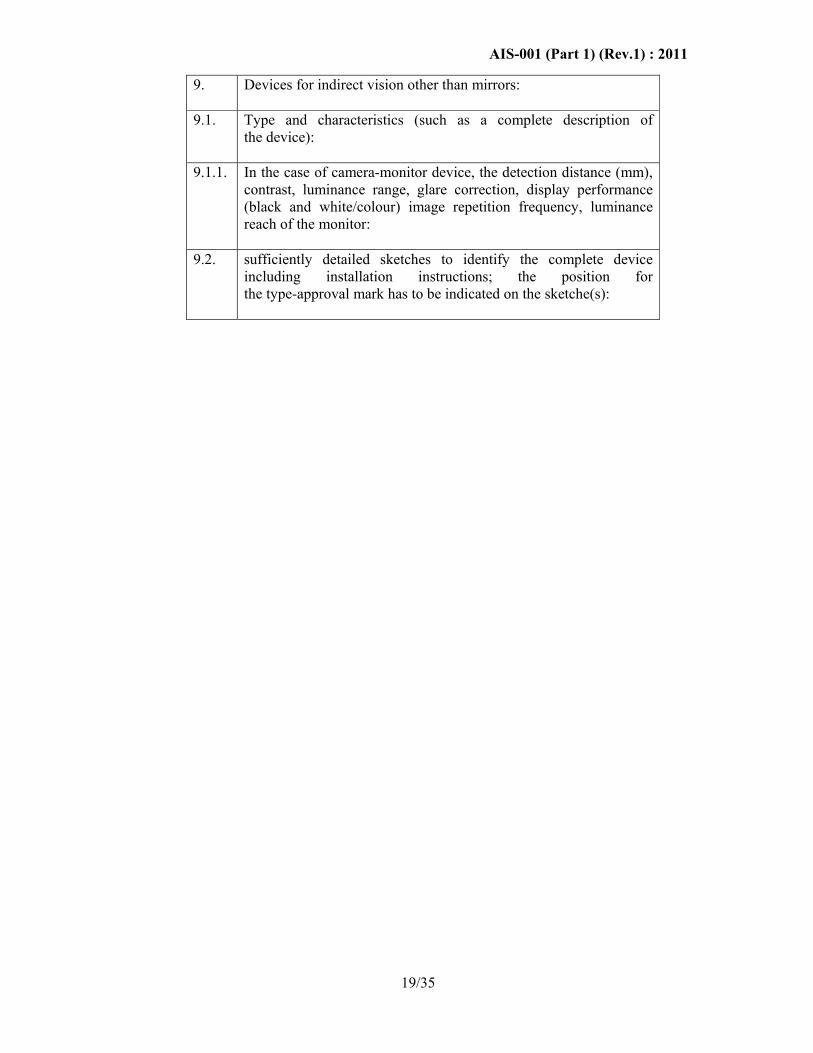
9. Devices for indirect vision other than mirrors:
9.1. Type and characteristics (such as a complete description of the device):
9.1.1. In the case of camera-monitor device, the detection distance (mm), contrast, luminance range, glare correction, display performance (black and white/colour) image repetition frequency, luminance reach of the monitor:
9.2. sufficiently detailed sketches to identify the complete device including installation instructions; the position for the type-approval mark has to be indicated on the sketche(s):

AIS-001 (Part 1) (Rev.1) : 2011
20/35
ANNEX B Reserved
ANNEX C Reserved
ANNEX D Reserved
ANNEX E Reserved
AIS-001 (Part 1) (Rev.1) : 2011
21/35
ANNEX F (See 6.1.2.2.5)
TEST METHOD FOR DETERMINING REFLECTIVITY
F-1. DEFINITIONS
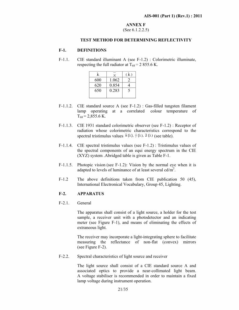
F-1.1. CIE standard illuminant A (see F-1.2) : Colorimetric illuminate,
respecting the full radiator at T68 = 2 855.6 K.
λ x ( λ ) 600 1.062 2 620 0.854 4 650 0.283 5
F-1.1.2. CIE standard source A (see F-1.2) : Gas-filled tungsten filament lamp operating at a correlated colour temperature of T68 = 2,855.6 K.
F-1.1.3. CIE 1931 standard colorimetric observer (see F-1.2) : Receptor of radiation whose colorimetric characteristics correspond to the spectral tristimulus values x z ( ), ( (λ γ λ λ), ) (see table).
F-1.1.4. CIE spectral tristimulus values (see F-1.2) : Tristimulus values of the spectral components of an equi energy spectrum in the CIE (XYZ) system .Abridged table is given as Table F-1.
F-1.1.5. Photopic vision (see F-1.2): Vision by the normal eye when it is adapted to levels of luminance of at least several cd/m2.
F-1.2 The above definitions taken from CIE publication 50 (45), International Electronical Vocabulary, Group 45, Lighting.
F-2. APPARATUS
F-2.1. General
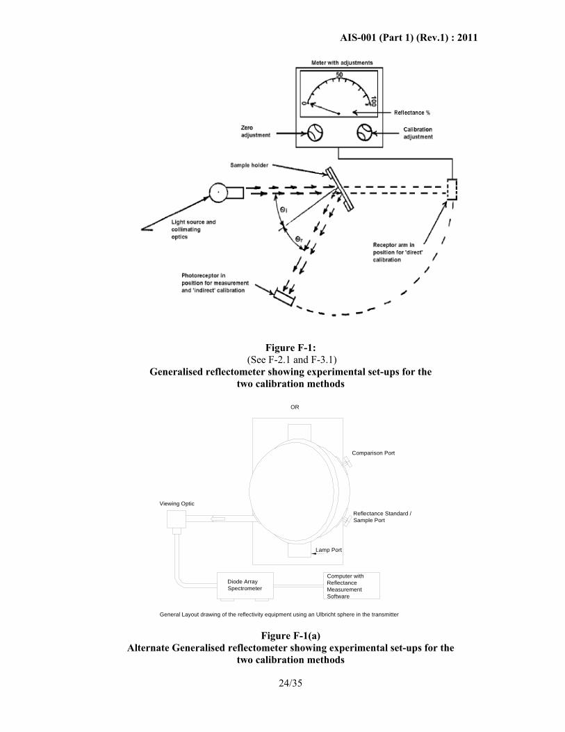
The apparatus shall consist of a light source, a holder for the test sample, a receiver unit with a photodetector and an indicating meter (see Figure F-1), and means of eliminating the effects of extraneous light.
The receiver may incorporate a light-integrating sphere to facilitate measuring the reflectance of non-flat (convex) mirrors (see Figure F-2).
F-2.2. Spectral characteristics of light source and receiver
The light source shall consist of a CIE standard source A and associated optics to provide a near-collimated light beam. A voltage stabiliser is recommended in order to maintain a fixed lamp voltage during instrument operation.

AIS-001 (Part 1) (Rev.1) : 2011
22/35
The receiver shall have a photodetector with a spectral response proportional to the photopic luminosity function of the CIE (1931) standard colorimetric observer (see table). Any other combination of illuminate-filter-receptor giving the overall equivalent of CIE standard illuminant A and photopic vision may be used. When an integrating sphere is used in the receiver, the interior surface of the sphere shall be coated with a matt (diffusive) spectrally non-selective white coating.
F-2.3. Geometrical conditions
The angle of the incident beam ( θ ) should preferably be 0.44 ± 0.09 rad (25 ± 5°) from the perpendicular to the test surface and shall not exceed the upper limit of the tolerance (i.e. 0.53 rad or 30°). The axis of the receptor shall make an angle ( θ ) with this perpendicular equal to that of the incident beam (see Figure F-1).
The incident beam upon arrival at the test surface shall have a diameter of not less than 13 mm (0.5 in.). The reflected beam shall not be wider than the sensitive area of the photodetector, shall not cover less than 50 per cent of such area, and as nearly as possible shall cover the same area segment as used during instrument calibration.
When an integrating sphere is used in the receiver section, the sphere shall have a minimum diameter of 127 mm (5 in.). The sample and incident beam apertures in the sphere wall shall be of such a size as to admit the entire incident and reflected light beams. The photodetector shall be so located as not to receive direct light from either the incident or the reflected beam.
F-2.4. Electrical characteristics of the photodetector-indicator unit
The photo detector output as read on the indicating meter shall be a linear function of the light intensity of the photosensitive area. Means (electrical and/or optical) shall be provided to facilitate zeroing and calibration adjustments. Such means shall not affect the linearity or the spectral characteristics of the instrument. The accuracy of the receptor indicator unit shall be within ± 2 per cent of full scale, or ± 10 per cent of the magnitude of the reading, whichever is the smaller.
F-2.5. Sample holder
The mechanism shall be capable of locating the test sample so that the axes of the source arm and receptor intersect at the reflecting surface. The reflecting surface may lie within or at either face of the mirror sample, depending on whether it is a first surface, second surface or prismatic "flip" type mirror.

AIS-001 (Part 1) (Rev.1) : 2011
23/35
F-3. PROCEDURE
F-3.1. Direct calibration method
In the direct calibration method, air is used as the reference standard. This method is applicable for those instruments, which are so constructed as to permit calibration at the 100 per cent point by swinging the receiver to a position directly on the axis of the light source (see Figure F-1).
It may be desired in some cases (such as when measuring low-reflectivity surfaces) to use an intermediate calibration point (between 0 and 100 per cent on the scale) with this method. In these cases, a neutral density filter of known transmittance shall be inserted in the optical path, and the calibration control shall then be adjusted until the meter reads the percentage transmission of the neutral density filter. This filter shall be removed before reflectivity measurements are performed.
F-3.2. Indirect calibration method
The indirect calibration method is applicable in the case of instruments with fixed source and receiver geometry. A properly calibrated and maintained reflectance standard is required. This reference standard should preferably be a flat mirror with a reflectance value as near as possible to that of the test samples.
F-3.3. Flat mirror measurement
The reflectance of flat mirror samples may be measured on instruments employing either the direct or the indirect calibration method. The reflectance value is read directly from the indicating meter.
F-3.4. Non-flat (convex) mirror measurement
Measurement of the reflectance of non-flat (convex) mirrors requires the use of instruments which incorporate an integrating sphere in the receiver unit (see Figure F-2). If the instrument-indicating meter indicates ne divisions with a standard mirror of E percent reflectance, then, with a mirror of unknown reflectance, nx divisions will correspond to a reflectance of X percent, in accordance with the formula:
X Enn
x
e=
AIS-001 (Part 1) (Rev.1) : 2011
24/35
Figure F-1: (See F-2.1 and F-3.1)
Generalised reflectometer showing experimental set-ups for the two calibration methods
Comparison Port
Reflectance Standard /Sample Port
Diode ArraySpectrometer
Computer withReflectanceMeasurementSoftware
Viewing Optic
Lamp Port
OR
General Layout drawing of the reflectivity equipment using an Ulbricht sphere in the transmitter
Figure F-1(a)
Alternate Generalised reflectometer showing experimental set-ups for the two calibration methods

AIS-001 (Part 1) (Rev.1) : 2011
25/35
Figure 2
(See F-2.1 and F-3.4)
Generalised reflectometer, incorporating an integrating sphere
in the receiver

AIS-001 (Part 1) (Rev.1) : 2011
26/35
Table F-1 (See F-1.1.4.)
SPECTRAL TRISTIMULUS VALUS FOR THE CIE 1931 STANDARD COLORMETRIC OBSERVER (see note below)
This table is taken from CIE publication 50 (45) (1970)
λ nm
_ x(λ)
_ y(λ)
_ z(λ)
380 0.001 4 0,000 0 0,006 5 390 0,004 2 0,000 1 0,020 1 400 0,014 3 0,000 4 0,067 9 410 0,043 5 0,001 2 0,207 4 420 0,134 4 0,004 0 0,645 6 430 0,283 9 0,011 6 1,385 6 440 0,348 3 0,023 0 1,747 1 450 0,336 2 0,038 0 1,772 1 460 0,290 8 0,060 0 1,669 2 470 0,195 4 0,091 0 1,287 6 480 0,095 6 0,139 0 0,813 0 490 0,032 0 0,208 0 0,465 2 500 0,004 9 0,323 0 0,272 0 510 0,009 3 0,503 0 0,158 2 520 0,063 3 0,710 0 0,078 2 530 0,165 5 0,862 0 0,042 2 540 0,290 4 0,954 0 0,020 3 550 0,433 4 0,995 0 0,008 7560 0,594 5 0,995 0 0,003 9 570 0,762 1 0,952 0 0,002 1 580 0,916 3 0,870 0 0,001 7 590 1,026 3 0,757 0 0,001 1 600 1,062 2 0,631 0 0,000 8 610 1,002 6 0,503 0 0,000 3 620 0,854 4 0,381 0 0,000 2 630 0,642 4 0,265 0 0,000 0 640 0,447 9 0,175 0 0,000 0 650 0,283 5 0,107 0 0,000 0 660 0,164 9 0,061 0 0,000 0 670 0,087 4 0,032 0 0,000 0 680 0,046 8 0,017 0 0,000 0690 0,022 7 0,008 2 0,000 0 700 0,011 4 0,004 1 0,000 0 710 0,005 8 0,002 1 0,000 0 720 0,002 9 0,001 0 0,000 0 730 0,001 4 0,000 5 0,000 0 740 0,000 7 0,000 2 (*) 0,000 0750 0,000 3 0,000 1 0,000 0 760 0,000 2 0,000 1 0,000 0 770 0,000 1 0,000 0 0,000 0 780 0,000 0 0,000 0 0.000 0
(*) : Changed in 1966 (from 3 to 2) Note: Abridged table. The values of y ( ) = V ( )λ λ are rounded off to four decimal places.

AIS-001 (Part 1) (Rev.1) : 2011
27/35
EXPLANATORY FIGURE
Example of device for Measuring the Reflection Factor of Spherical Mirrors
C = Receiver
D = Diaphragm
E = Window of entry
F = Window of measurement
L = Lens
M = Object window
S = Light source
(S) = Integrating sphere

AIS-001 (Part 1) (Rev.1) : 2011
28/35
ANNEX G (See 2.1.1.5 and 2.1.1.6)
PROCEDURE FOR DETERMINING THE RADIUS OF CURVATURE "r" OF THE REFLECTING SURFACE
OF A MIRROR
G-1. MEASUREMENT
G-1.1. Equipment
A "spherometer" similar to the one described in Figure G-1 of this annex having the indicated distances between the tracing pin of the dial gauge and the fixed legs of the bar is used.
G-1.2. Measuring points
G-1.2.1.
The principal radii of curvature shall be measured at three points situated as close as possible to positions at ⅓ , ½ and ⅔ of the distance along the arc of the reflecting surface passing through the centre of this surface and parallel to segment b, or of the arc passing through the centre of the reflecting surface which is perpendicular to it if this arc is the longer.
G-1.2.2.
Where, owing to the size of the reflecting surface, it is impossible to obtain measurements in the directions defined in 2.1.1.6. of this standard, testing agency may take measurements at the said point in two perpendicular directions as close as possible to those prescribed above.
G-2. CALCULATION OF THE RADIUS OF CURVATURE "r"
"r" expressed in mm is calculated from the formula
3
321 ppp rrrr
++=
where:
rp1 = the radius of curvature at the first measuring point,
rp2 = the radius of curvature at the second measuring point,
rp3 = the radius of curvature at the third measuring point,

AIS-001 (Part 1) (Rev.1) : 2011
29/35
Figure G-1
Spherometer (see G-1.1.)

AIS-001 (Part 1) (Rev.1) : 2011
30/35
ANNEX H Reserved
ANNEX J Reserved
ANNEX K Reserved

AIS-001 (Part 1) (Rev.1) : 2011
31/35
ANNEX L (See 7.5)
CRITERIA FOR EXTENSION OF APPROVAL
L-1 The verification/tests to be carried out for extending the approval to
changes in the parameters are listed in the Table L-1 below:
L-2 Changes other than those listed above are considered to be having no adverse effect on Rear View Mirror.
Table L-1
1. Make (trade name of
manufacturer): If different manufacturer complete type approval to be carried out. In case of changes in the name of manufacturerer’s or trademark for commercial reasons, type approval shall be extended without any testing.
2. Type and general commercial description(s):
In the case of type change, subject to other provisions of this table, all verification shall be carried out. In case of change in commercial description, type approval shall be extended without any testing, unless additional tests are called for, because of changes in technical parameters.
3. Means of identification of the type, if indicated on the device:
Type approval shall be extended without any testing.
4. Category of vehicle for which the device is intended:
No extension of approval is required
5. Name and address of manufacturer:
Same as for sl. No. 1
6. Location and method of affixing of the approval mark:
Type approval shall be extended without any testing.
7. Address(es) of assembly plant(s):
Verification of compliance to following requirements in AIS-037 need be carried out: - 5.0 Initial documentary appraisal - 6.0 Pre-test inspection Subject to compliance of the above type approval shall be extended without any further testing of samples.

AIS-001 (Part 1) (Rev.1) : 2011
32/35
8. Mirrors (state for each mirror):
8.1. Variant Based on the change in parameters listed in
this table
8.2. Sketch for the identification of the mirror:
No verification required.
8.3. Details of the method of attachment:
See 8.8
8.4 Dimensions of reflecting surfaces.
If maximum and minimum dimensions are type approved and changed dimensions are within these values, no test is required, other wise dimensional check to be conducted.
8.5 Change in Radius of curvature of reflecting surface.
Radius of curvature to be verified.
8.6 Change in reflective coating.
Reflectivity test to be verified.
8.7 Increase in cross-section of material and hardness of stem.
Bending and impact tests are to be conducted.
8.8 Changes in mounting dimensions adversely affecting, the performance against impact / bending test.
If height is reduced and/or horizontal distance between centre of the mirror to the base is reduced, bending test and Impact test to be conducted.
8.9 Overall shape of Housing Bending and impact tests are to be conducted. Note :Bending test is applicable only for rear mirrors described in Part 2 of this standard
9 Devices for indirect vision other than mirrors:
As agreed between test agency and device manufacturer/ applicant.

AIS-001 (Part 1) (Rev.1) : 2011
33/35
ANNEX M (See introduction)
COMPOSITION OF AISC PANEL ON REAR VIEW MIRRORS*
Convener
Mr. T. M. Balaraman Hero Honda Motors Ltd., (SIAM)
Members Representing
Mr. A. S. Bhale The Automotive Research Association of India (ARAI)
Mr. B. V. Shamsundara The Automotive Research Association of India (ARAI)
Mr. D. P. Saste Central Institute of Road Transport (CIRT)
Mr. V. D. Chavan Central Institute of Road Transport (CIRT)
Dr. Madhusudan Joshi International Centre for Automotive Technology (ICAT)
Mr. G.R.M. Rao Vehicle Research & Dev. Estt. (VRDE)
Dr. N. Karuppaiah National Automotive Testing and R&D Infrastructure Project (NATRIP)
Mr. K. K. Gandhi Society of Indian Automobile Manufacturers (SIAM)
Mr. G. K. Binani Society of Indian Automobile Manufacturers (SIAM) (Tata Motors Ltd)
Mr. P. K. Banerjee Society of Indian Automobile Manufacturers (SIAM) (Tata Motors Ltd)
Mr. R. M. Kanitkar Society of Indian Automobile Manufacturers (SIAM) (Force Motors Ltd.)
Mr. Z. A. Mujawar Society of Indian Automobile Manufacturers (SIAM) (Mahindra and Mahindra Ltd)
Mr. Nagendra H. V. Society of Indian Automobile Manufacturers (SIAM) (Toyota Kirloskar Motor Pvt. Ltd)
Mr. Prakash Vemali Society of Indian Automobile Manufacturers (SIAM) (Mercedes Benz India Ltd. )
Mr. Jitendra Malhotra Society of Indian Automobile Manufacturers (SIAM) (Maruti Suzuki India Ltd)
Mr. Sumit Sharma Society of Indian Automobile Manufacturers (SIAM) (Volkswagen India Private Ltd.)
Mr. Harjeet Singh Society of Indian Automobile Manufacturers (SIAM) (Hero Honda Motors Ltd)
Mr. Harsh Agrawal Society of Indian Automobile Manufacturers (SIAM) (Hero Honda Motors Ltd)
Mr. S Ramiah Society of Indian Automobile Manufacturers (SIAM) (TVS Motor Company Limited)
AIS-001 (Part 1) (Rev.1) : 2011
34/35
Mr. T.C. Gopalan, Tractor Manufacturers Association (TMA)
Mr. K. N. D. Nambudiripad Automotive Component Manufacturers Association (ACMA)
Mr. G. V. George FIEM Industries Ltd. (ACMA)
Mr. Rajagopalan FIEM Industries Ltd. (ACMA)
Mr. Virendra Sachdev Lumax Industries Ltd. (ACMA)
Mr. Sagar Kulkarni Rinder India Pvt. Ltd. (ACMA)
Mr. T. V. Singh Bureau of Indian Standards (BIS)
Mr. Rajiv Agarwal All India Auto & Miniature Bulbs & Component Mfrs. Association
Mr. C. K. Choudhari All India Auto & Miniature Bulbs & Component Mfrs. Association
* At the time of approval of this Automotive Industry Standard (AIS)

AIS-001 (Part 1) (Rev.1) : 2011
35/35
ANNEX N
(See introduction)
COMMITTEE COMPOSITION * Automotive Industry Standards Committee
Chairman
Shri Shrikant R. Marathe Director The Automotive Research Association of India, Pune
Members Representing
Representative from
Ministry of Road Transport & Highways (Dept. of Road Transport & Highways), New Delhi
Representative from
Ministry of Heavy Industries & Public Enterprises (Department of Heavy Industry), New Delhi
Shri S. M. Ahuja Office of the Development Commissioner, MSME, Ministry of Micro, Small & Medium Enterprises, New Delhi
Shri T. V. Singh Bureau of Indian Standards, New Delhi
Director Shri D. P. Saste (Alternate)
Central Institute of Road Transport, Pune
Dr. M. O. Garg Indian Institute of Petroleum, Dehra Dun
Shri C. P. Ramnarayanan Vehicles Research & Development Establishment, Ahmednagar
Representatives from Society of Indian Automobile Manufacturers
Shri T.C. Gopalan Tractor Manufacturers Association, New Delhi
Shri K.N.D. Nambudiripad
Automotive Components Manufacturers Association of India, New Delhi
Member Secretary
Mrs. Rashmi Urdhwareshe Sr. Deputy Director
The Automotive Research Association of India, Pune * At the time of approval of this Automotive Industry Standard (AIS)