automation systems and control componentsdocs-europe.electrocomponents.com/webdocs/0b68/... ·...
TRANSCRIPT

HydraulicsElectric Drivesand Controls
Linear Motion andAssembly Technologies Pneumatics Service
Automation Systems and Control Components
Consistent, intelligent and future-proof


Bosch Rexroth is the worldwide leader in all relevant drive, control and motion technologies – with industry-specific automation systems and innovative control components.
Competent in Automation
Content
Automation Systems Summary
Control Components Summary
IndraControl L – Rack-Based Controls
IndraControl V – Human-Machine Interfaces (HMI) and Industrial PCs
Inline – Cabinet-mount (IP20) I/O Technology
Fieldline – Machine-Mount (IP67) I/O Technology
Software – IndraWorks Engineering Framework
Glossary
Advanced Information: www.boschrexroth.com/brc/products
IndraMotion MLD – Drive-Based Motion-Logic System
IndraMotion MLC – Controller-Based Motion-Logic System
IndraMotion MTX – CNC System for Machine Tools
IndraMotion for Metal Forming – Solution for the Forming Industry
IndraMotion for Handling – Solution for the Handling, Assembly and Robotics Industry
IndraMotion for Packaging – Solution for the Food Processing and Packaging Industries
IndraLogic – Open PLC System
4
1
164
4
10
2
12
2.1
20
2.2
24
2.3
30
2.4
40
2.5
42
2.6
44
2.7
46
3
48
3.1
68
3.2
98
3.3
144
3.4
154
3.5

01 Competent in Automation4
The Rexroth Automation House now provides an entirely new automation system. This unique modular system increases the capacity, flexibility and, above all, the economic efficiency of your production facilities. The ideal interplay of motion, logic and visualization allows you to access tomorrow’s machine automation – in the following industries:• Machine tool manufacture• Food processing and packaging industries• Handling and assembly• Forming technology
Uniform engineering software for all solutionsIndraWorks now allows you to solve all of your tasks with one single software – from project planning and programming to visualization and diagnostics. Its innovative feature: IndraWorks is consistently available in all of our automation systems as a uniform engineering software – will profit from the fast access to all functions and data of the control components and from the increased transparency of your automation solution.
Rexroth Automation House –Simply Smart
Consistent PLC logic according to IEC 61131-3Using the PLC runtime system IndraLogic in all of your automation solutions, you will be able to standardize your application programs in conformity with IEC 611313. With its userfriendly handling, this programming system that is fully integrated in IndraWorks facilitates the creation of modularized and objectoriented applications.
Maximum flexibility with integrated motion logicThe family of open system software combines all components of the Automation House to provide consistent solutions with motion and logic control. Using IndraMotion, you can implement all of your centralized and distributed control designs, customized to your industryspecific requirements.
Scalable platforms for all control topologiesThe scalable control, visualization and I/O hardware platforms allow easy, flexible and consistent automation of your applications. Combined with open communication interfaces, these hardware platforms provide automation solutions that are also reliable in the future and allow factory automation with any degree of freedom.
Safety on board – certified integrated safety systemThe internal drive safety system “safety on board” provides reliable personnel protection for all motion applications. With the IndraDrive family, the “safety on board” system, certified according to DIN 9541, provides comprehensive safety functions which you can easily integrate in your applications by simple parameterization.
SERCOS III – Ethernet-based communicationThe 3rd generation SERCOS interface meets all requirements for a forwardlooking machine network – open, consistent and fast. From drives and controls to I/O peripherals, all automation components are easily combined to form a transparent and capable overall system. With realtime and innovative features, SERCOS III provides maximum performance and flexibility in all applications.

Com
pete
nt in
Aut
omat
ion
5
1IndraWorksConsistent engineering tool for project planning, programming, visualization and diagnostics IndraMotion Scalable system software for highly productive motion control applications
IndraLogic IECconforming PLC solution for intelligent automation
IndraControl Scalable control platform for more transparency in manufacture
IndraDrive and IndraDynIntelligent drive solution and comprehensive motor range for optimum dynamics
Our Automation House, which forms a unique modular system, accommodates all constituents for successful automati-on designs – from drives and controls to a capable framework for uniform engineering and user-friendly operation. This innovative system opens up all choices of modern automation technolo-gy – consistent, intelligent and future-proof.

01 Competent in Automation6
Automation Systems for Your Industry
Our innovative automation systems have set milestones in focused industries. These best-in-class solutions from the Rexroth Automation House present the decisive added value: absolute user-orientation, leading technology and worldwide usability – with the only goal of optimizing the economic utilization of machines and plants.
IndraMotion MLCController-based motion-logic solution for all multi-axis applications
IndraMotion MLDDrive-based automation solution for single-axis and multi-axis applications
IndraLogicOpen PLC systems for universal use
IndraMotion for PackagingFlexible automation system for food processing and packaging machines
IndraMotion for HandlingTurnkey automation system for handling, assembly and robotics
IndraMotion for Metal FormingScalable automation system for materi-al transport in the forming industry
IndraMotion MTXHighly productive CNC solution for all machine tools

Com
pete
nt in
Aut
omat
ion
1
Control Components for Your Automation System
With IndraControl, the Rexroth Automation House offers all control platforms for your preferred automation solutions. Irrespective of the system you selected, you will profit from consistent and harmonized hardware architectures – versatile, sturdy and modular.
IndraControl LRack-based controls
IndraControl VHuman-Machine Interface (HMI) devices and industrial PCs
InlineCabinet-mount (IP20) I/O technology
FieldlineMachine-mount (IP6) I/O technology
IndraWorksEngineering framework

01 Competent in Automation
Bildname S2373_01G.fh11Ersetzt durch
Bilddatenbank qja qneinNr.:
Produktkatalog qja qneinNr.:
Bild-/Grafikart CD-ROM
Auftraggeber BRC/MKT1Aufnahmedatum/-ort 01.2005Auftragnehmer Techno-ArtworksVerwendungsnachweis
Bildname S2373_01G.fh11Ersetzt durch
Bilddatenbank qja qneinNr.:
Produktkatalog qja qneinNr.:
Bild-/Grafikart CD-ROM
Auftraggeber BRC/MKT1Aufnahmedatum/-ort 01.2005Auftragnehmer Techno-ArtworksVerwendungsnachweis
Bildname S2478_02G.fh11Ersetzt durch
Bilddatenbank qja qneinNr.:
Produktkatalog qja qneinNr.:
Bild-/Grafikart
Auftraggeber BRC/MKT1Aufnahmedatum/-ort 01.2005Auftragnehmer Techno-ArtworksVerwendungsnachweis
IndraMotion MLDDrive-based motion-logic system
IndraMotion MLCController-based motion-logic system
IndraWorks
IndraControl V
IndraControl L
Inline/Fieldline
IndraDrive
Input/output modules
Bus couplerPROFIBUS
Bus couplerDeviceNet
I/O block Digital
I/O block Analog
Fieldbus
Bildname S2447_01G.fh11Ersetzt durch
Bilddatenbank qja qneinNr.:
Produktkatalog qja qneinNr.:
Bild-/Grafikart Weltkugel
Auftraggeber BRC/MKT1Aufnahmedatum/-ort 01.2005Auftragnehmer Techno-ArtworksVerwendungsnachweis
VPP21 VPP VPB VSP
Ethernet
L10 L15 L20 L40
Controller-based control
Industrial PC
IndraDrive C IndraDrive M
Drives
Bildname S2478_01G.fh11Ersetzt durch
Bilddatenbank qja qneinNr.:
Produktkatalog qja qneinNr.:
Bild-/Grafikart
Auftraggeber BRC/MKT1Aufnahmedatum/-ort 01.2005Auftragnehmer Techno-ArtworksVerwendungsnachweis
Automation System and Control Components at a Glance

Com
pete
nt in
Aut
omat
ion
9
1
Bildname S2373_01G.fh11Ersetzt durch
Bilddatenbank qja qneinNr.:
Produktkatalog qja qneinNr.:
Bild-/Grafikart CD-ROM
Auftraggeber BRC/MKT1Aufnahmedatum/-ort 01.2005Auftragnehmer Techno-ArtworksVerwendungsnachweis
Bildname S2478_02G.fh11Ersetzt durch
Bilddatenbank qja qneinNr.:
Produktkatalog qja qneinNr.:
Bild-/Grafikart
Auftraggeber BRC/MKT1Aufnahmedatum/-ort 01.2005Auftragnehmer Techno-ArtworksVerwendungsnachweis
IndraMotion MTXCNC systems
Bildname S2373_01G.fh11Ersetzt durch
Bilddatenbank qja qneinNr.:
Produktkatalog qja qneinNr.:
Bild-/Grafikart CD-ROM
Auftraggeber BRC/MKT1Aufnahmedatum/-ort 01.2005Auftragnehmer Techno-ArtworksVerwendungsnachweis
Bildname S2478_02G.fh11Ersetzt durch
Bilddatenbank qja qneinNr.:
Produktkatalog qja qneinNr.:
Bild-/Grafikart
Auftraggeber BRC/MKT1Aufnahmedatum/-ort 01.2005Auftragnehmer Techno-ArtworksVerwendungsnachweis
IndraLogicPLC systems
Modular Inline bus terminal
Fieldline M12PROFIBUS
Fieldline M12DeviceNet
Fieldline M12 PROFIBUSbus coupler
Fieldline M8 Bus couplerSERCOS III
I/O block Digital
SERCOS III
I/O block Analog
SERCOS III
Input/output modules
Bildname S2097_01G.fh11Ersetzt durch
Bilddatenbank qja qneinNr.:
Produktkatalog qja qneinNr.:
Bild-/Grafikart Laptop Frontansicht
Auftraggeber BRC/MKT1Aufnahmedatum/-ort 01.2005Auftragnehmer Techno-ArtworksVerwendungsnachweis
Bildname S2373_01G.fh11Ersetzt durch
Bilddatenbank qja qneinNr.:
Produktkatalog qja qneinNr.:
Bild-/Grafikart CD-ROM
Auftraggeber BRC/MKT1Aufnahmedatum/-ort 01.2005Auftragnehmer Techno-ArtworksVerwendungsnachweis
Engineering
Control panels/keyboards Embedded PC Controller
VSB VDP VAK VAM VEP VEH VCP VCH
L45 L65
IndraDrive C IndraDrive M
Drives
Industrial PC

10 02 Automation Systems
Automation Systems – CNC, PLC and Motion Control

Aut
omat
ion
Sys
tem
s
IndraLogic – Open PLC System
IndraMotion MLC – Controller-Based Motion-Logic System
IndraMotion for Metal Forming – Solution for the Forming Industry
IndraMotion MTX – CNC System for Machine Tools
IndraMotion for Handling – Solution for the Handling, Assembly and Robotics Industry
IndraMotion MLD – Drive-Based Motion-Logic System
12
2.1
44
2.7
42
2.6
40
2.5
30
2.4
24
2.3
20
2.2
IndraMotion for Packaging – Solution for the Food Processing and Packaging Industries
11
2

12 2.1 Automation Systems • IndraLogic
IndraLogic – Open PLC Systems for Universal UseThe Rexroth IndraLogic PLC system sets new standards for open auto-mation with a consistent control, programming and communication design. Whether PC, controller or drive, IndraLogic provides a uniform platform for any configuration while being fully compatible with the IEC 61131-3 standard.
On various platforms, the capacity and functionality of IndraLogic can be customized precisely to your centralized and distributed automation architecture:• Controller-based PLC systems - IndraLogic L10 - IndraLogic L15 - IndraLogic L20 - IndraLogic L40
• PC-based PLC systems - IndraLogic VE
- IndraLogic VS - IndraLogic VP
Your benefits• High performance through
innovative control platform • All degrees of freedom for
centralized and distributed automation
• Highest performance and functionality
• Scalable PLC solution according to IEC 61131-3
• Open standardized communication interfaces
• Comprehensive libraries and function blocks for motion control according to PLCopen
• Consistent PLC runtime system in all automation solutions
• Quick expansion and easy connec-tion of I/O and function modules
• Integrated or easy connection of HMI solutions
• Intuitive engineering and diagnostics with IndraWorks
Rexroth IndraLogic is the complete PLC solution from the future-oriented Automation House for successful auto-mation designs – efficient, scalable and standardized.

Aut
omat
ion
Sys
tem
s • I
ndra
Logi
c
13
2.1
IndraControl L IndraControl V
IndraDyn IndraDyn
Inline Fieldline
IndraDrive IndraDrive
Ethernet
Engineering Operation
Fieldbus
Fieldbus Fieldbus Fieldbus
IndraControl V
IndraControl V
Additional information
Control hardware IndraControl L10, L15, L20, L40 Chapter 3.1Centralized and distributed input/output modules
in IP20 Inline Chapter 3.3
Distributed input/output modules in IP67 Fieldline Chapter 3.4
Visualization devices, controller-based IndraControl VCP Chapter 3.2
Visualization devices, embedded PC IndraControl VEP Chapter 3.2
Visualization devices, standard industrial PC IndraControl VSP, VSB Chapter 3.2
Visualization devices, high-end industrial PC IndraControl VPP, VPB Chapter 3.2
Drive family IndraDrive IndraDrive and IndraDyn product catalog
Engineering framework IndraWorks Chapter 3.5
Your benefit
Efficient andstandardizedl Consistent automation solutionl Comprehensive functions and numerous interfacesl Uniform engineering and convenient operation
IndraLogic – the PLC solution in the controller or in the PC can always be customized precisely to your centralized and distributed automation architectures.
IndraControl L IndraControl V
IndraDyn IndraDyn
Inline Fieldline
IndraDrive IndraDrive
Ethernet
Engineering Operation
Fieldbus
Fieldbus Fieldbus Fieldbus
IndraControl V
IndraControl V
Logiccontroller-based
IndraLogic L
LogicPC-based
IndraLogic V

14 2.1 Automation Systems • IndraLogic
IndraLogic L10 and L15
Technical data IndraLogic L10 and L15
Hardware platform IndraControl L10 and L15
User memory (code/data) 3 MB (1/2 MB)
Retentive memory 16 kB
Number of tasks 4
Types of task Time-controlled, cyclic, periodic, free-running, controlled by external event
Processing time Typically 300 µsec (1,000 instructions in IL, bit and word commands)
I/O 128 I/Os (centralized), 300, 8 In/4 Out on board
Programming system IndraWorks
Programming languages (IEC 61131-3) ST, IL, LD, SFC, FBD, CFC
Programming interface Ethernet
Functions for program test Break point, single step, singly cycle, write/force, monitoring, sampling trace, simulation, online change
Supplied libraries IEC 61131-3 standard, communication
Communication interfaces Ethernet TCP/IP, EtherNet/IP Adapter (Slave), PROFInet Slave (L10/L15), SERCOS III Easy I/O (L15)
Ordering data
Order code Description
FWA-CML10-IL*-xxVRS-DO-0003 IndraLogic L10 firmware
FWA-CML15-IL*-xxVRS-DO-0003 IndraLogic L15 firmware
Ordering data for accessories
Order code Description
SWA-IWORKS-IL*-xxVRS-DO-CD650 Engineering framework IndraWorks
Documentations
Order code Description
in preparation
xx = software/firmware version

Aut
omat
ion
Sys
tem
s • I
ndra
Logi
c
15
2.1
IndraLogic L20
Technical data IndraLogic L20
Hardware platform IndraControl L20
User memory (code/data) 3 MB (1/2 MB)
Retentive memory 32 kB
Number of tasks 8
Types of task Time-controlled, cyclic, periodic, free-running, controlled by external event
Processing time Typically 150 µsec (1,000 instructions in IL, bit and word commands)
I/O 256 I/Os (centralized), distributed via PROFIBUS DP interface (max. 126 users with 9 kB I/O each), 8 In/8 Out on board
Programming system IndraWorks
Programming languages (IEC 61131-3) ST, IL, LD, SFC, FBD, CFC
Programming interface Ethernet, RS232
Functions for program test Break point, single step, singly cycle, write/force, monitoring, sampling trace, simulation, online change
Supplied libraries PLCopen, IEC 61131-3 standard, communication
Communication interfaces RS232, Ethernet TCP/IP, EtherNet/IP Adapter (slave), PROFIBUS DP
Ordering data
Order code Description
FWA-CML20*-IL*-xxVRS-DO-0003 IndraLogic L20 firmware
Ordering data for accessories
Order code Description
SWA-IWORKS-IL*-xxVRS-DO-CD650 Engineering framework IndraWorks
Documentations
Order code Description
DOK-CONTRL-IL**PRO*Vxx-AWxx-DE-P PLC program development with IndraLogic (German)
DOK-CONTRL-IL**PRO*Vxx-AWxx-EN-P PLC program development with IndraLogic (English)
DOK-CONTRL-IC*L20*****-AWxx-DE-P IndraLogic L20 PLC system description, operating and programming instructions (German)
DOK-CONTRL-IC*L20*****-AWxx-EN-P IndraLogic L20 PLC system description, operating and programming instructions (English)
xx = software/firmware version

16 2.1 Automation Systems • IndraLogic
IndraLogic L40
Technical data IndraLogic L40
Hardware platform IndraControl L40
User memory (code/data) 8 MB (4/4 MB)
Retentive memory 64 kB
Number of tasks 16
Types of task Time-controlled, cyclic, periodic, free-running, controlled by external event
Processing time Typically 70 µsec (1,000 instructions in IL, bit and word commands)
I/O 512 I/Os (centralized), extension via PROFIBUS DP (max. 126 users with 8 kB I/O each), 8 In/8 Out on board
Programming system IndraWorks
Programming languages (IEC 61131-3) ST, IL, LD, SFC, FBD, CFC
Programming interface Ethernet, RS232
Functions for program test Break point, single step, singly cycle, write/force, monitoring, sampling trace, simulation, online change
Supplied libraries PLCopen, IEC 61131-3 standard, communication
Communication interfaces RS232, Ethernet TCP/IP, EtherNet/IP Adapter (Slave), PROFIBUS DP
Ordering data
Order code Description
FWA-CML40*-IL*-xxVRS-DO-0008 IndraLogic L40 firmware
Ordering data for accessories
Order code Description
SWA-IWORKS-IL*-xxVRS-DO-CD650 Engineering framework IndraWorks
Documentations
Order code Description
DOK-CONTRL-IL**PRO*Vxx-AWxx-DE-P PLC program development with IndraLogic (German)
DOK-CONTRL-IL**PRO*Vxx-AWxx-EN-P PLC program development with IndraLogic (English)
DOK-CONTRL-IL**IC*L40*****-AWxx-DE-P IndraLogic L40 PLC system description, operating and programming instructions (German)
DOK-CONTRL-IL**IC*L40*****-AWxx-EN-P IndraLogic L40 PLC system description, operating and programming instructions (English)
xx = software/firmware version

Aut
omat
ion
Sys
tem
s • I
ndra
Logi
c
17
2.1
Technical data IndraLogic VPP 21 IndraLogic VP
Hardware platform IndraControl VPP 21 IndraControl VPP, VPB
Operating systems Windows XP Windows XP/Windows 2000
Realtime VxWorks/VxWin VxWorks/VxWin
Runtime system IndraLogic IndraLogic
User memory (code/data) 24 MB (8/16 MB) 24 MB (8/16 MB)
Retentive memory 2 MB, battery-buffered 2 MB on HD (with UPS)
Number of tasks 32 32
Types of task Time-controlled, cyclic, free-running, event-controlled Time-controlled, cyclic, free-running, event-controlled
Processing timeTypically 50 µsec (1,000 instructions in IL,
bit and word commands)
Typically 30 µsec (1,000 instructions in IL,
bit and word commands)
I/ODistributed via PROFIBUS DP (max. 126 users,
with 7 kB I/O each)
Distributed via PROFIBUS DP (max. 126 users,
with 7 kB I/O each)
Programming system IndraWorks IndraWorks
Programming languages (IEC 61131-3) ST, IL, LD, SFC, FBD, CFC ST, IL, LD, SFC, FBD, CFC
Programming interfaces Ethernet, RS232 or directly on target hardware Ethernet, RS232 or directly on target hardware
Supplied libraries PLCopen, IEC 61131-3 standard, communication PLCopen, IEC 61131-3 standard, communication
Communication interfaces RS232, USB, Ethernet TCP/IP, EtherNet/IP Adapter (Slave) RS232, USB, Ethernet TCP/IP, EtherNet/IP Adapter (Slave)
Functions for program testBreak point, single step, singly cycle, write/force, monitoring,
sampling trace, simulation, online change
Break point, single step, singly cycle, write/force, monitoring,
sampling trace, simulation, online change
Ordering data
Type code Description
FWA-VPP21*-IL*-xxVRS-D0-0032 IndraLogic VPP 21 firmware
FWA-VPXVSX-IL*-xxVRS-D0-0024 IndraLogic VP firmware
Ordering data for accessories
Type code Description
SWA-IWORKS-IL*-xxVRS-D0-CD650 Engineering framework IndraWorks
Documentations
Type code Description
DOK-CONTRL-IL**PRO*Vxx-AWxx-DE-P PLC program development with IndraLogic (German)
DOK-CONTRL-IL**PRO*Vxx-AWxx-EN-P PLC program development with IndraLogic (English)
DOK-CONTRL-IL*VPP*21*****-AWxx-DE-P IndraLogic VPP 21 system description (German)
DOK-CONTRL-IL*VPP*21*****-AWxx-EN-P IndraLogic VPP 21 system description (English)
DOK-CONTRL-IL*V*******-AWxx-DE-P IndraLogic V system description (German)
DOK-CONTRL-IL*V*******-AWxx-EN-P IndraLogic V system description (English)
xx = software/firmware version
IndraLogic VP

18 2.1 Automation Systems • IndraLogic
IndraLogic VS
Technical data IndraLogic VS
Hardware platform IndraControl VSP, VSB
Operating systems Windows XP
Realtime VxWorks/VxWin
Runtime system IndraLogic
User memory (code/data) 24 MB (8/16 MB)
Retentive memory 2 MB on HD (with UPS)
Number of tasks 32
Types of task Time-controlled, cyclic, free-running, event-controlled
Processing time Typically 50 µsec (1,000 instructions in IL, bit and word commands)
I/O Distributed via PROFIBUS DP (max. 126 users, with 7 kB I/O each)
Programming system IndraWorks
Programming languages (IEC 61131-3) ST, IL, LD, SFC, FBD, CFC
Programming interfaces Ethernet, RS232 or directly on target hardware
Supplied libraries PLCopen, IEC 61131-3 standard, communication
Communication interfaces RS232, Ethernet TCP/IP, EtherNet/IP Adapter (Slave), PROFIBUS DP
Functions for program test Break point, single step, singly cycle, write/force, monitoring, sampling trace, simulation, online change
Ordering data
Type code Description
FWA-VPXVSX-IL*-xxVRS-D0-0024 IndraLogic VS firmware
Ordering data for accessories
Type code Description
SWA-IWORKS-IL*xxVRS-D0-CD650 Engineering framework IndraWorks
Documentations
Type code Description
DOK-CONTRL-IL**PRO*Vxx-AWxx-DE-P PLC program development with IndraLogic (German)
DOK-CONTRL-IL**PRO*Vxx-AWxx-EN-P PLC program development with IndraLogic (English)
DOK-CONTRL-IL*V******-AWxx-DE-P IndraLogic VP/VS system description (German)
DOK-CONTRL-IL*V******-AWxx-EN-P IndraLogic VP/VS system description (English)
xx = software/firmware version

Aut
omat
ion
Sys
tem
s • I
ndra
Logi
c
19
2.1
Technical data IndraLogic VE
Hardware platform IndraControl VEP
Operating systems Windows CE .Net 4.2
Realtime Windows CE .Net 4.2
Runtime system IndraLogic
User memory (code/data) 12 MB (4/8 MB)
Retentive memory 256 kB on flash
Number of tasks 16
Types of task Time-controlled, periodic, free-running, event-controlled
Processing time Typically 100 µsec (1,000 instructions in IL, bit and word commands)
I/O Distributed via PROFIBUS DP (max. 126 users, with 7 kB I/O each)
Programming system IndraWorks
Programming interface Ethernet
Programming languages (IEC 61131-3) ST, IL, LD, SFC, FBD, CFC
Functions for program test Break point, single step, singly cycle, write/force, monitoring, sampling trace, simulation, online change
Supplied libraries PLCopen, IEC 61131-3 standard, communication
Communication interfaces RS232, Ethernet TCP/IP, EtherNet/IP Adapter (Slave), field buses
Ordering data
Type code Description
SWL-VE**01-ILC-xxVRS-NN IndraLogic VE firmware
Ordering data for accessories
Type code Description
SWA-IWORKS-IL*-xxVRS-D0-CD650 Engineering framework IndraWorks
Documentations
Type code Description
DOK-CONTRL-IL**PRO*Vxx-AWxx-DE-P PLC program development with IndraLogic (German)
DOK-CONTRL-IL**PRO*Vxx-AWxx-EN-P PLC program development with IndraLogic (English)
DOK-CONTRL-IL*VEP*****-AWxx-DE-P IndraLogic VE system description (German)
DOK-CONTRL-IL*VEP*****-AWxx-EN-P IndraLogic VE system description (English)
xx = software/firmware version
IndraLogic VE

20 2.2 Automation Systems • IndraMotion MLD
IndraMotion MLD – Drive-Based Automation Solution for Single-Axis and Multi-Axis ApplicationsIndraMotion MLD combines motion and PLC functions to form a modern open automation platform for modu-lar machine designs. The decentra-lized control architecture establish-es a compact motion-logic system, based on the scalable IndraDrive platform, so that higher-order con-trols are no longer necessary.
This drive-based solution is available as a single-axis control for simple applications as well as a multi-axis control for applications with a maxi-mum of 8 axes. Ready-to-use function libraries simplify the use of intelligent drive functions of our IndraDrives. In addition, PLCopen-conforming func-tion blocks provide access to standard-ized motion-control functions. The open technology and communication interfaces facilitate integration of IndraMotion MLD in your automation design.
Your benefits• Compact system for modular distri-
buted architectures• Scalable as single-axis or multi-axis
control• Electronic synchronization of up
to 8 servo-axes• Ready-to-use function libraries
according to PLCopen• Intelligent drive functions already
integrated• Optional technology and communi-
cation interfaces• Drive-integrated motion-control
and PLC runtime system according to IEC 61131-3
• Integrated Safe Motion system according to EN 954-1, Cat. 3
• Intuitive engineering with the IndraWorks software framework
• Additional software options with function libraries, technology packages and turnkey solutions
IndraMotion MLD from Rexroth helps you to integrate your valuable know-how directly in the drive, thus ensuring your competitive edge.

Aut
omat
ion
Sys
tem
s • I
ndra
Mot
ion
MLD
21
2.2
IndraMotion MLD combines high-capacity motion and PLC functions to form an efficient motion-logic system.
Additional information
Drive platform IndraDrive IndraDrive and IndraDyn product catalog
Visualization devices, controller-based IndraControl VCP Chapter 3.2
Centralized and distributed input/output modules in IP20 Inline Chapter 3.3
Distributed input/output modules in IP67 Fieldline Chapter 3.4
Engineering framework IndraWorks Chapter 3.5
Your benefit
Compact, intelligent and economicl Very cost effective solution for single-axis and multi-
axis applications without any additional hardwarel Minimized engineering through conformity with
IEC and PLCopenl Faster implementation of your system solution
through predefined technology packages
Motion-Logicdrive-based
IndraMotion MLD-S IndraMotion MLD-M
Ethernet
PROFIBUS
MLD
IndraControl V
InlineInline
IndraDrive
Ethernet
PROFIBUS
Ethernet
EngineeringOperation
MLD
IndraControl V
IndraDyn IndraDyn
Ethernet
PROFIBUS
MLD
IndraControl V
InlineInline
IndraDrive
Ethernet
PROFIBUS
Ethernet
EngineeringOperation
MLD
IndraControl V
IndraDyn IndraDyn
Motion-Logicdrive-based

2222 2.2 Automation Systems • IndraMotion MLD
Technical data MLD-S MLD-S MLD-M
BASIC ADVANCED ADVANCED
Number of axes 1 1 up to 8
Hardware requirements (Master) BASIC control unit CSB ADVANCED control unit CSH CSH control units with optional CCD
Optional firmware TF ML ML
Performance
Depending on the utilization of the
BASIC drive
100 µs per 1,000 instructions in IL with bit and word processing
Tasks
Number of tasks 4
Types of task Time-controlled, periodic, free-running or event-controlled
Cycle time 2 ms 1 ms 1 ms
Program memory
Firmware 03VRS 192 kB –
Firmware 04VRS Typically 350 kB
Programming
Programming system IndraWorks
Programming languagesInstruction List (IL), Structured Text (ST), Ladder Diagram (LD), Sequential Function Chart (SFC),
Function Block Diagram (FBD), Continuous Flow Chart (CFC)
Programming interfaces RS232, Ethernet
Functions for program test Break point, single step, singly cycle, write/force, monitoring, sampling trace, simulation, online change
Supplied libraries System-specific, drive-specific and PLCopen
Master communication
SERCOS interface, PROFIBUS, PROFInet IO, DeviceNet, CANopen, parallel interface, analog interface,
analog/digital for OPEN LOOP operation, IndraMotion MLD
Digital inputs and outputsInputs 51) 7
Depending on the number and type of
control units and options used
Inputs/outputs (any adjustment) 31) 4
MD1 option – 12 I/8 O
MD2 option – 16 I/16 O
Parallel interface 16 I/16 O 16 I/16 O
Analog inputs and outputs
From control unit –1) 1 I/2 O Depending on the number and type of
control units and options used With MA1 option 2 I/2 O 2 I/2 O1) with control unit CSB01.1C
IndraMotion MLD
Ordering data for firmware and software
Type code Description
Firmware for IndraMotion MLD
FWA-INDRV*-MPB-xxVRS-xx-x-xxx-TF IndraDrive BASIC firmware with TF option
FWA-INDRV*-MPH-xxVRS-xx-x-xxx-ML IndraDrive ADVANCED firmware with ML option
IndraWorks software
SWA-IWORKS-D*-xxVRS-DO-CD650 Engineering framework IndraWorks
SWS-IWORKS-CAM-xxVRS-DO License for CamBuilder option
xx = IndraDrive configuration or software/firmware version

Aut
omat
ion
Sys
tem
s • I
ndra
Mot
ion
MLD
23
2.2

24 2.3 Automation Systems • IndraMotion MLC
The compact motion-logic system IndraMotion MLC from Rexroth gives you any freedom you wish for your consistent and modern ma-chine automation. Innovative soft-ware and firmware functions with simple engineering and open system interfaces provide maximum flexi-bility in all motion applications with real-time.
By combining motion-control, PLC and technology functions, you can synchronize multi-axis applications very easily – freely scalable for centralized or distributed solutions with a flexible control platform. Motion functions, such as Master axes, electronic gears and cams, can be used quickly and transparently. The PLCopen-confor-ming user interface with its standard-ized function blocks according to IEC 61131-3 facilitates integration in various machine designs.
Your benefits• Quick integration in various pro-
cesses, machines and plants• Scalable for centralized and distri-
buted architectures with maximum performance
• Integrated runtime system with motion, logic and robot control as well as innovative technology function blocks
• Function block libraries conforming to IEC 61131-3 and PLCopen
• Compact control platform IndraControl L with flexible expansion capability
• Open interfaces for communication and technology functions
• Intuitive framework IndraWorks for all engineering tasks
IndraMotion MLC – Controller-Based Solution with Integrated Motion Logic
IndraMotion MLC is the integrated controller-based system solution from the Rexroth Automation House. Ready- to-use technology functions accelerate engineering, for example in packaging and handling applications.

Aut
omat
ion
Sys
tem
s • I
ndra
Mot
ion
MLCIndraControl L IndraControl L
IndraDyn IndraDyn
Inline
IndraDrive
IndraControl V
IndraDrive
Ethernet
Engineering Operation
Inline
Cross Communication Fieldbus
Centralized or distributed – IndraMotion MLC reduces expenditure and expense for integration, test, diagnostics and maintenance in the overall automation of your machines and systems.
Additional information
Control hardware IndraControl L40 Chapter 3.1
Centralized and distributed input/output modules in IP20 Inline Chapter 3.3
Distributed input/output modules in IP67 Fieldline Chapter 3.4
Visualization devices, controller-based IndraControl VCP Chapter 3.2
Visualization devices, embedded PC IndraControl VEP Chapter 3.2
Visualization devices, standard industrial PC IndraControl VSP Chapter 3.2
Drive family IndraDrive IndraDrive and IndraDyn product catalog
Engineering framework IndraWorks Chapter 3.5
Your benefit
Simple, open and flexiblel Overall solution with integrated motion logicl Simple in use and scalable in performance and
functionl Optimum performance for all mechatronic solutions
25
2.3
Motion-Logiccontroller-based
IndraMotion MLC

2626 2.3 Automation Systems • IndraMotion MLC
IndraMotion MLC
1 Drives
1.1 IndraDrive BASIC and ADVANCED with MPB/MPH firmware l
Dual-axis control units with MPD firmware l
1.2 IndraDrive Mi l
1.3 EcoDrive Cs l
1.4 SERCOS Pack Profile l
1.5 HNC100 Hydraulic drive l
1.6 Master communication
1.6.1 SERCOS interface l
1.6.2 SERCOS III l
1.6.3 Min. SERCOS cycle time 1 ms
2 IndraControl L40 control
2.1 Interfaces
2.1.1 SERCOS interface On board l
2.1.2 SERCOS III Function module °
2.1.3 Cross-communication of Master axes (ELS) SERCOS interface function module °
2.1.4 PROFIBUS Master On board l
2.1.5 PROFIBUS Slave On board l
2.1.6 PROFIBUS Master Function module °
2.1.7 DeviceNet Master Function module °
2.1.8 RS232 On board l
2.1.9 Ethernet 10/100 Mpbs On board l
2.1.10 Cam controller Function module °
2.1.11 Master axis encoder Function module q
2.1.12 SRAM Function module for robot control °
2.2 On-board-diagnostics and settings
2.2.1 Status display (boot, SERCOS, test) Display l
2.2.2 Errors, warnings, messages, system reset Display, keys l
2.2.3 Ethernet settings (IP address) Display, keys l
2.2.4 Voltage monitoring, watchdog l
2.2.5 Relay output ready for operation l
3 Inputs and outputs
3.1 On board
3.1.1 High-speed digital inputs Interrupt capability, typically 50 µs 8
3.1.2 High-speed digital outputs 0.5 A, typically 500 µs 8
3.2 Local
3.2.1 FAST I/O function module – high-speed digital inputs Interrupt capability, typically 40 µs 8/16
3.2.2 FAST I/O function module – high-speed digital outputs Max. 0.5 A, typically 70 µs 8/16
3.2.3 Inline (digital, analog, relay, technology) 64 bytes, max. 512 I/O °
3.3 Distributed via fieldbus
3.3.1 Inline (IP20)
3.3.1.1 PROFIBUS On board °
3.3.1.2 DeviceNet Function module °
3.3.2 Fieldline (IP67)
3.3.2.1 PROFIBUS On board °
3.3.2.2 DeviceNet Function module °
l°q
= default= optional= in preparation

Aut
omat
ion
Sys
tem
s • I
ndra
Mot
ion
MLC
27
2.3
27
2.1
4 HMI
4.1 IndraControl VCP (controller-based)
PROFIBUS °
DeviceNet °
Ethernet l
4.2 IndraControl VEP (embedded PC) Ethernet, OPC °
4.3 IndraControl VSP, VPP (industrial PC) Ethernet, OPC °
5 Communication interfaces
5.1 SERCOS interface Real-time motion bus l
5.2 SERCOS III Real-time Ethernet bus °
5.3 Master axis grouping SERCOS interface °
SERCOS III (C2C) °
5.4 Control grouping Ethernet TCP/UDP/IP l
5.5 PROFIBUS DP-V1 Master e. g. peripherals, HMI l/°
5.6 PROFIBUS DP-V1 Slave l
5.7 DeviceNet-Master (explicit/implicit messaging) e. g. peripherals, HMI °
5.8 RS232 l
5.9 Ethernet TCP/IP (e. g. HMI, engineering) l
EtherNet/IP Adapter (Slave) l
6 Firmware functions
6.1 General
6.1.1 Runtime system Integrated motion-logic system l
6.2 Logic control
6.2.1 IndraLogic kernel according to IEC 61131-3 l
6.2.2 Freely configurable tasks Time-controlled, cyclic, free-runing, event-controlled 8
6.2.3 External event tasks Synchronously with SERCOS cycle 1
System-specific (e. g. error reaction) 1
6.2.4 Status/setting of cycle times e. g. SERCOS cycle (1/2/4/8 ms) l
6.2.5 Program organization According to IEC 61131-3 l
6.2.6 Motion commands according to PLCopen (choice)
MC_MoveAbsolute l
MC_MoveRelative l
MC_MoveVelocity l
MC_Home l
MC_CamIn, MC_CamOut l
MC_GearIn, MC_GearOut l
6.2.7 Extended motion commands (choice)
MB_ReadListParameter l
MB_WriteListParameter l
MB_GearInPos l
ML_PhasingSlave l
MB_ClearAxisError l
MB_ClearSystemError l
6.3 Motion control
6.3.1 Number of axes Virtual, real, encoder, grouping 32
6.3.2 Synchronization (ELS – electronic line shaft) Multi-axes
6.3.2.1 Virtual axes Virtual masters l
6.3.2.2 Encoder axes Real masters l
6.3.2.3 Real axes Servo drives l
l°q
= default= optional= in preparation

2828 2.3 Automation Systems • IndraMotion MLC
IndraMotion MLC
6 Firmware functions
6.3.2.4 Grouped axes Cross-communication l
6.3.2.5 Dynamic synchronization l
6.3.2.6 Master axis grouping l
6.3.2.7 Master axis cascading l
6.3.3 Positioning Single-axis l
6.3.4 Electronic gears l
6.3.5 Electronic cams
6.3.5.1 In the drive Max. 1,024 intermediate points 4
6.3.5.2 In the control Profiles per axis with up to 16 segments 2
6.3.6 Diagnostics Status, warnings, errors
6.3.6.1 Function blocks Software l
6.3.6.2 Parameter access to diagnostics memory Software l
6.3.6.3 Locally via display Control hardware l
6.3.6.4 Axis monitoring e. g. utilization, encoders, limit values l
6.3.6.5 Diagnostics memory 64 kB, max. 999 messages l
6.4 Robot control
6.4.1 Number of interpolation axes 6
6.4.2 Sequential motion programming l
6.4.3 Multi-axis kinematics l
6.4.4 Kinematics transformations l
6.4.5 LINEAR, CIRCULAR, PTP types of interpolation l
6.4.6 Block transitions l
6.4.7 Override l
6.4.8 Teach-in function l
6.4.9 Approximate positioning l
6.4.10 Belt synchronization l
6.4.11 Speed limitation For path and axes l
6.4.12 Acceleration limitation For path and axes l
6.4.13 Safety zones
6.5 Technology (choice)
6.5.1 Register control l
6.5.2 Flying cut-off l
6.5.3 Measuring wheel l
6.5.4 Probe l
6.5.5 Cam control l
6.5.6 Cross cutter l
6.5.7 Sag control l
6.5.8 Winder l
6.5.9 Tension control l
l°q
= default= optional= in preparation
Aut
omat
ion
Sys
tem
s • I
ndra
Mot
ion
MLC
29
2.3
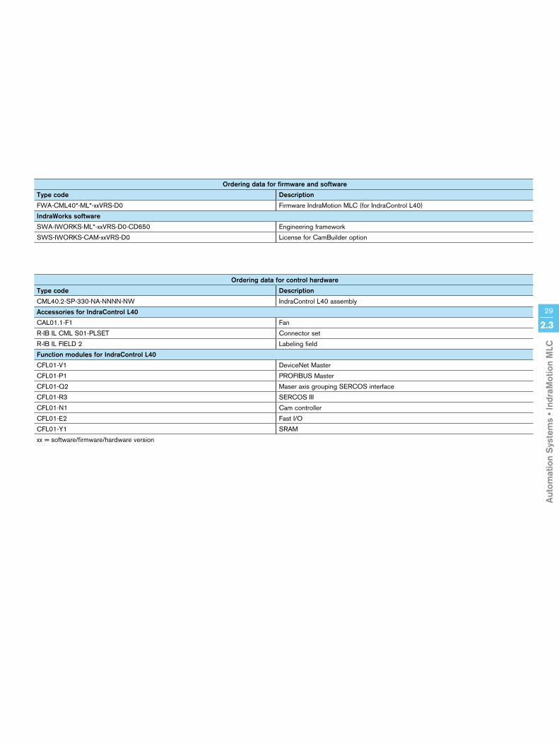
Ordering data for firmware and software
Type code Description
FWA-CML40*-ML*-xxVRS-D0 Firmware IndraMotion MLC (for IndraControl L40)
IndraWorks software
SWA-IWORKS-ML*-xxVRS-D0-CD650 Engineering framework
SWS-IWORKS-CAM-xxVRS-D0 License for CamBuilder option
Ordering data for control hardware
Type code Description
CML40.2-SP-330-NA-NNNN-NW IndraControl L40 assembly
Accessories for IndraControl L40
CAL01.1-F1 Fan
R-IB IL CML S01-PLSET Connector set
R-IB IL FIELD 2 Labeling field
Function modules for IndraControl L40
CFL01-V1 DeviceNet Master
CFL01-P1 PROFIBUS Master
CFL01-Q2 Maser axis grouping SERCOS interface
CFL01-R3 SERCOS III
CFL01-N1 Cam controller
CFL01-E2 Fast I/O
CFL01-Y1 SRAM
xx = software/firmware/hardware version

30 2.4 Automation Systems • IndraMotion MTX
Rexroth IndraMotion MTX is the individually scalable CNC platform with integrated PLC for successful machining and forming designs. Excellent performance data and comprehensive technology func-tions open new horizons for maxi-mum productivity and flexibility.
Wether you control a standard machine or a fully automated production system – IndraMotion MTX always ensures highly dynamic processing with mini-mized down times in your application. The following system versions are available:
• IndraMotion MTX compact – space-saving rack version for distributed control technology
• IndraMotion MTX standard – plug-in control in a sturdy industrial PC
• IndraMotion MTX performance – high-capacity plug-in control in a special high-end industrial PC
IndraMotion MTX –Highly Productive CNC Solution for All Machine Tools
IndraMotion MTX is the customized CNC solution for turning, milling, drilling, grinding, bending, nibbling, punching and laser cutting.
Your benefits• Advanced technology functions for
turning, milling, drilling, grinding, bending, nibbling, punching and laser cutting
• Open system platform with modular configuration
• Uniform operational design for easy programming
• Performance and function individually scalable
• Innovative CNC kernel with com-prehensive technology functions and libraries
• Shortest CNC cycle times, even for high-speed machining
• Minimum PLC processing times• Flexibly configurable user interface • Particular machine-specific
functions• Open standards for easy connec-
tion of higher-order ERP systems

Aut
omat
ion
Sys
tem
s • I
ndra
Mot
ion
MTX
31
2.4
Engineering
Ethernet
IndraDrive
Inline Fieldline
IndraDyn
IndraControl V
IndraControl V
IndraControl V
Plug-in-CardVAC 30
Esc
With its modular system design, its open control structure and its international standard interfaces, IndraMotion MTX solves any machining task in CNC technology with utmost dynamics and precision.
Additional information
Visualization devices, high-end industrial PC IndraControl VPP Chapter 3.2
Visualization devices, standard industrial PC IndraControl VSP Chapter 3.2
Visualization devices, displays IndraControl VDP Chapter 3.2
Visualization devices, embedded PC IndraControl VEP, VEH Chapter 3.2
Visualization devices, controller-based IndraControl VCP Chapter 3.2
Visualization devices, machine control panels IndraControl VAM Chapter 3.2
Centralized and distributed input/output modules in IP20 Inline Chapter 3.3
Distributed input/output modules in IP67 Fieldline Chapter 3.4
Drive family IndraDrive IndraDrive and IndraDyn product catalog
Engineering framework IndraWorks Chapter 3.5
Your benefit
Open, complete and efficientl Highest manufacturing precision down to the
nanometer rangel Modern CNC solution for excellent performancel Shortest CNC and PLC cycle times for dynamic
machining
CNCPC-based
IndraMotion MTX

3232 2.4 Automation Systems • IndraMotion MTX
1 Machining technologies MTX compact MTX standard MTX performance
1.1 Turning l l l
1.2 Milling l l l
1.3 Drilling l l l
1.4 Grinding – l l
1.5 Nibbling, laser cutting – l l
1.6 Reforming – l l
2 Axis control MTX compact MTX standard MTX performance
2.1 Default number of axes 8 l 8 l 8 l
2.2 Max. number of axes 8 l 8 l 64 °
2.3 Max. number of spindles thereof 2 l 2 l 32 °
2.4 Default number of independent channels 2 l 2 l 3 l
2.5 Max. number of independent channels 2 l 2 l 12 °
2.6 Default number of interpolating axes per channel 4 l 4 l 4 l
2.7 Max. number of interpolating axes per channel 4 l 4 l 8* °
2.8 Linear axes l l l
2.9 Rotary axes l l l
2.10 Endlessly turning rotary axis l l l
2.11 Hirth axes l l l
2.12 Spindle/C-axis switching l l l
2.13 Max. number of gantry axes per channel 4 2 ° 4 2 ° 8 2 3 °
2.14 Max. number of synchronous groups per channel 4 1 2 ° 4 1 2 ° 8 1 2 3 °
2.15 Channel-crossing axis transfer l l l
2.16 Cams l l l
2.17 Software limit l l l
2.18 Main spindle synchronization 1 2 ° 1 2 ° 1 2 3 °
2.19Integrated safety system of Cat. 3 according to DIN 954-1
(safe stop, safely reduced speed, safe end positions)o o o
3 Interpolation functions MTX compact MTX standard MTX performance3.1 Linear interpolation l l l
3.2 Linear interpolation with/without exact stop l l l
3.3Circular interpolation with radius and center-point programming,
helical interpolationl l l
3.4 Circular interpolation with tangential entry l l l
3.5 Rigid tapping cycle l l l
3.6 Thread cutting l l l
3.7 NC block preview, look-ahead with jerk limitation Max. 30 blocks l Max. 30 blocks l Max. 1,000 blocks °
3.8 5/6 axis transformation with TCP programming – – 3 °
3.9 Jogging with active transformation – – 3 °
3.10
Spline interpolation,
C1 + C2, continuous cubic splines,
B-splines, NURBS
1 2 ° 1 2 ° 1 2 3 °
3.11 Nanometer resolution l l l
l °n®
DefaultOptionalOptional in connection with a PCOptional with IndraDrive
123
“Turning 1” technology package“Milling 1” technology package“Milling 2” technology package
45
“Turning” shop programming“Milling” shop programming
* Option requiring official approval for export according to Part I C of the Export List (EG-VO), Pos. 2D002
IndraMotion MTX
Aut
omat
ion
Sys
tem
s • I
ndra
Mot
ion
MTX
33
2.4
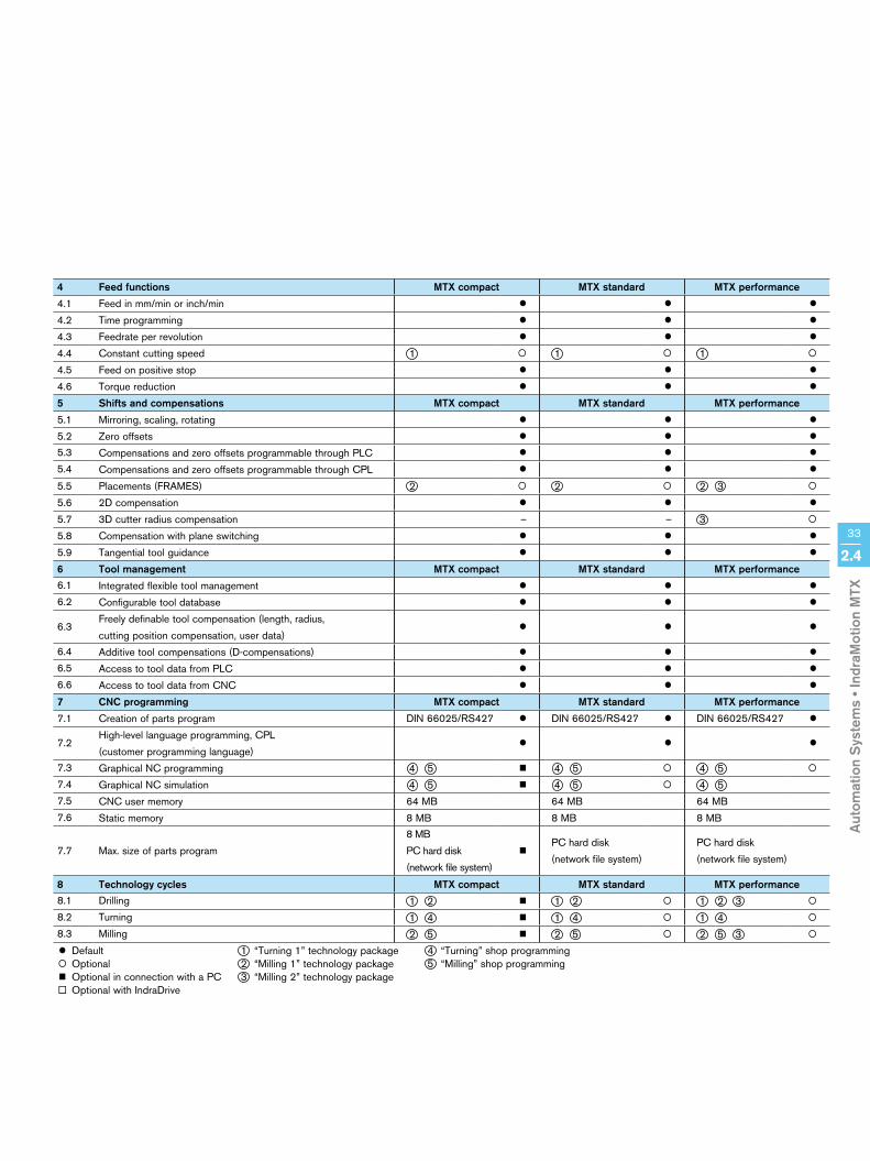
4 Feed functions MTX compact MTX standard MTX performance
4.1 Feed in mm/min or inch/min l l l
4.2 Time programming l l l
4.3 Feedrate per revolution l l l
4.4 Constant cutting speed 1 ° 1 ° 1 °
4.5 Feed on positive stop l l l
4.6 Torque reduction l l l
5 Shifts and compensations MTX compact MTX standard MTX performance
5.1 Mirroring, scaling, rotating l l l
5.2 Zero offsets l l l
5.3 Compensations and zero offsets programmable through PLC l l l
5.4 Compensations and zero offsets programmable through CPL l l l
5.5 Placements (FRAMES) 2 ° 2 ° 2 3 °
5.6 2D compensation l l l
5.7 3D cutter radius compensation – – 3 °
5.8 Compensation with plane switching l l l
5.9 Tangential tool guidance l l l
6 Tool management MTX compact MTX standard MTX performance6.1 Integrated flexible tool management l l l
6.2 Configurable tool database l l l
6.3Freely definable tool compensation (length, radius,
cutting position compensation, user data)l l l
6.4 Additive tool compensations (D-compensations) l l l
6.5 Access to tool data from PLC l l l
6.6 Access to tool data from CNC l l l
7 CNC programming MTX compact MTX standard MTX performance
7.1 Creation of parts program DIN 66025/RS427 l DIN 66025/RS427 l DIN 66025/RS427 l
7.2High-level language programming, CPL
(customer programming language)l l l
7.3 Graphical NC programming 4 5 n 4 5 ° 4 5 °
7.4 Graphical NC simulation 4 5 n 4 5 ° 4 5
7.5 CNC user memory 64 MB 64 MB 64 MB
7.6 Static memory 8 MB 8 MB 8 MB
7.7 Max. size of parts program
8 MB
PC hard disk
(network file system)
nPC hard disk
(network file system)
PC hard disk
(network file system)
8 Technology cycles MTX compact MTX standard MTX performance8.1 Drilling 1 2 n 1 2 ° 1 2 3 °
8.2 Turning 1 4 n 1 4 ° 1 4 °
8.3 Milling 2 5 n 2 5 ° 2 5 3 °
l °n®
DefaultOptionalOptional in connection with a PCOptional with IndraDrive
123
“Turning 1” technology package“Milling 1” technology package“Milling 2” technology package
45
“Turning” shop programming“Milling” shop programming

3434 2.4 Automation Systems • IndraMotion MTX
9 Functions MTX compact MTX standard MTX performance
9.1 Dwell time in seconds l l l
9.2 Acceleration programming, loop gain programming l l l
9.3 Homing through NC program l l l
9.4 Absolute dimension, relative dimension l l l
9.5 Switching between inch and mm l l l
9.6 Probe, static/on-the-fly measurement l l l
9.7 Read process and drive data through SERCOS interface l l l
9.8 Roundings and chamfers l l l
9.9 Laser power control l l l
9.10 Digitizing l l l
9.11 NC block defined by PLC l l l
10 Support for control elements MTX compact MTX standard MTX performance
10.1 Configurable operator screens n l l
10.2 Cycle header/input support, OEM cycles n l l
10.3 NC program restart/block search l l l
10.4 Dry run l l l
10.5 Retracting from and returning to the contour l l l
11 PLC programming MTX compact MTX standard MTX performance
11.1 Integrated PLC: IndraLogic l l l
11.2Programming languages according to IEC 61131-3
(IL, LD, CFC, ST, SFC, FBD)l l l
11.3 PLC program memory 8 MB 8 MB 8 MB
11.4 Number of high-speed inputs/outputs – 8/8 ° 8/8 °
11.5 Number of fieldbus inputs/outputs in bytes 8,192/8,192 8,192/8,192 8,192/8,192
11.6 Multitasking l l l
11.7 Max. number of PLC tasks 16 16 16
12 Diagnostic and startup tools MTX compact MTX standard MTX performance
12.1Integrated, system-crossing
engineering framework IndraWorksn l l
12.2 Automatic system monitoring units l l l
12.3 Instructions and error messages in plaintext n l l
12.4 Integrated drive project planning n l l
12.5 Drive oscilloscope n l l
12.6 Integrated PLC project planning n l l
12.7 Logic analyzer n l l
12.8 Remote diagnostics I-Remote ° ° °
13 Open architecture MTX compact MTX standard MTX performance
13.1 Configurable user interface with all standard functions n l l
13.2 Projectable user-specific operator screens n l l
13.3Adaptation and integration through standardized interfaces
(OPC, XML, ActiveX, .NET)n l l
l °n®
DefaultOptionalOptional in connection with a PCOptional with IndraDrive
IndraMotion MTX

Aut
omat
ion
Sys
tem
s • I
ndra
Mot
ion
MTX
14 Control hardware and interfaces MTX compact MTX standard MTX performance
14.1 CPU IndraControl L40 Plug-in card Plug-in card
14.2Digital drive interface
SERCOS interface2 to 16 Mbauds l 2 to 16 Mbauds l 2 to 16 Mbauds l
14.3 PROFIBUS DP Master 12 Mbauds l 12 Mbauds l 12 Mbauds l
14.4 Ethernet 100 Mbits l 100 Mbits l 100 Mbits l
14.5 Ethernet/IP Adapter (Slave) ° – °
14.6 DeviceNet Scanner (Master) ° – °
15 Software and hardware MTX compact MTX standard MTX performance
15.1 Operating system Windows XP
15.2
Panel PC IndraControl VSP 16/40- CPU: Celeron, 2 GHz- RAM: 512 MB- Hard disk: min. 30 GB- TFT display: 12”/15”- TFT resolution: 800 x 600/1,024 x 768- Floppy disk (USB): 1.44 MB- DVD-RW/DVD-ROM drive- Ethernet, 100 Mbits, 2 COM, 1 LPT, keyboard, mouse- USB interface/IP65: 2/1- 16 machine control keys
° ° °
15.3
Panel PC IndraControl VPP 16/40- CPU: Celeron M, 1.3 GHz- RAM: 512 MB/1 GB- Shock-proof hard disk: min. 20 GB- TFT display: 12”/15”- TFT resolution: 800 x 600/1,024 x 768- Floppy disk (USB): 1.44 MB- DVD-RW/DVD-ROM drive- Ethernet, 100 Mbits, 2 COM, 1 LPT, keyboard, mouse- USB interface/IP65: 2/1- USV port (optional batteries)- 16 machine control keys- Integrated temperature and fan monitoring
° – °
15.4
Industrial PC IndraControl VSB 40- CPU: Celeron, 2 GHz- RAM: 512 MB- Hard disk: min. 30 GB- Floppy disk (USB): 1.44 MB- DVD-RW/DVD-ROM drive- Ethernet, 100 Mbits, 2 COM, 1 LPT, keyboard, mouse- USB interface/IP65: 2/0- 16 machine control keys
° ° °
15.5
Industrial PC IndraControl VPB 40- CPU: Celeron M, 1.3 GHz- RAM: 512 MB/1 GB- Shock-proof hard disk: min. 20 GB- Floppy disk (USB): 1.44 MB- DVD-RW/DVD-ROM drive- Ethernet, 100 Mbits, 2 COM, 1 LPT, keyboard, mouse- USB interface/IP65: 2/0- USV port (optional batteries)- Integrated temperature and fan monitoring
° – °
l °n®
DefaultOptionalOptional in connection with a PCOptional with IndraDrive
35
2.4

3636 2.4 Automation Systems • IndraMotion MTX
IndraMotion MTX compact
Ordering data for control hardware
Order code Description
CML40.2-SP-330-NA-NN-NN-NW IndraControl L40 with SERCOS interface, PROFIBUS interface
Ordering data for firmware and software
Order code Description
FWA-CML40*-MTX-xxVRS-NN Firmware for IndraMotion MTX compact
SWA-IWORKS-MTX-xxVRS-D0-CD650-SIMULATOR IndraWorks for IndraMotion MTX-CNC systems,
offline and remote programming, MTX simulator (DE/EN)
Ordering data for accessories
Order code Description
SWS-MTX***-RUN-NNVRS-D0-TUR1 Technology package – turning 1
SWS-MTX***-RUN-NNVRS-D0-SFPT Shop programming – turning (DE/EN)
SWS-MTX***-RUN-NNVRS-D0-BAZ1 Technology package – milling 1 (DE/EN)
SWA-MTX***-SED-xxVRS-IT-CD650 Language extension, Italian
SWA-MTX***-SED-xxVRS-FR-CD650 Language extension, French
SWA-MTX***-SED-xxVRS-CS-CD650 Language extension, Czech
SWA-MTX***-SED-xxVRS-RU-CD650 Language extension, Russian
SWA-MTX***-SED-xxVRS-PT-CD650 Language extension, Portuguese
SWA-MTX***-SED-xxVRS-SV-CD650 Language extension, Swedish
Documentations
Order code Description
DOK-MTX***-SYS*DES*Vxx-PRxx-EN-P System description, project planning
DOK-MTX***-SOFTINS*Vxx-IBxx-EN-P Software installation
DOK-MTX***-PLC*INT*Vxx-PRxx-EN-P PLC interface, project planning
DOK-MTX***-MA*PAR**Vxx-PAxx-EN-P Machine parameters, parameter description
DOK-MTX***-NC*OP***Vxx-AWxx-EN-P IndraMotion standard NC operation
DOK-MTX***-NC*FUNC*Vxx-FKxx-EN-P Functional description
DOK-MTX***-NC**PRO*Vxx-AWxx-EN-P Programming manual, application description
DOK-MTX***-SF*PROG*Vxx-AWxx-EN-P Turning and milling shop programming, operating and programming instructions
DOK-MTX***-DIAGMES*Vxx-IFxx-EN-P Diagnosis messages
DOK-CONTRL-IL**PRO*Vxx-AWxx-EN-P IndraLogic programming manual
DOK-MTX***-OPC*INT*Vxx-PRxx-EN-P OPC interface, project planning
DOK-IWORKS-IREMOTE*Vxx-AWxx-EN-P I-Remote maintenance software, application description
xx = software/firmware version

Aut
omat
ion
Sys
tem
s • I
ndra
Mot
ion
MTX
37
2.4
IndraMotion MTX standard
Ordering data for control hardware
Order code Description
CFG-VSN01E1-H-NN-NN-NN-NN-NN IndraControl VS basic device with IndraControl P40 plug-in card
CFG-VSN01E1-H-IC-NN-NN-NN-NNIndraControl VS basic device with IndraControl P40 plug-in card
and high-speed I/O interface (8 In/8 Out)
Ordering data for firmware and software
Order code Description
FWA-CMP40*-MTX-xxVRS-NN Firmware for IndraMotion MTX standard
SWA-IWORKS-MTX-xxVRS-D0-CD650-OPDENG Standard CNC operating and programming software (operation and engineering)
incl. WinStudio Lite Runtime and Editor (DE/EN)
SWA-IWORKS-MTX-xxVRS-D0-CD650-OPD Standard CNC operating software (operation) incl. WinStudio Lite Runtime (DE/EN)
SWA-IWORKS-MTX-xxVRS-D0-CD650-COM Communication interface for customer-specific user interfaces (DE/EN)
SWA-IWORKS-MTX-xxVRS-D0-CD650-SIMULATORIndraWorks for IndraMotion MTX-CNC systems,
offline and remote programming, MTX simulator (DE/EN)
Ordering data for accessories
Order code Description
SWS-MTX***-RUN-NNVRS-D0-TUR1 Technology package – turning 1
SWS-MTX***-RUN-NNVRS-D0-SFPT Shop programming – turning (DE/EN)
SWS-MTX***-RUN-NNVRS-D0-BAZ1 Technology package – milling 1 (DE/EN)
SWA-MTX***-SED-xxVRS-IT-CD650 Language extension, Italian
SWA-MTX***-SED-xxVRS-FR-CD650 Language extension, French
SWA-MTX***-SED-xxVRS-CS-CD650 Language extension, Czech
SWA-MTX***-SED-xxVRS-RU-CD650 Language extension, Russian
SWA-MTX***-SED-xxVRS-PT-CD650 Language extension, Portuguese
SWA-MTX***-SED-xxVRS-SV-CD650 Language extension, Swedish
Documentations
Order code Description
DOK-MTX***-SYS*DES*Vxx-PRxx-EN-P System description, project planning
DOK-MTX***-SOFTINS*Vxx-IBxx-EN-P Software installation
DOK-MTX***-PLC*INT*Vxx-PRxx-EN-P PLC interface, project planning
DOK-MTX***-MA*PAR**Vxx-PAxx-EN-P Machine parameters, parameter description
DOK-MTX***-NC*OP***Vxx-AWxx-EN-P IndraMotion standard NC operation
DOK-MTX***-NC*FUNC*Vxx-FKxx-EN-P Functional description
DOK-MTX***-NC**PRO*Vxx-AWxx-EN-P Programming manual, application description
DOK-MTX***-SF*PROG*Vxx-AWxx-EN-P Turning and milling shop programming, operating and programming instructions
DOK-MTX***-DIAGMES*Vxx-IFxx-EN-P Diagnosis messages
DOK-CONTRL-IL**PRO*Vxx-AWxx-EN-P IndraLogic programming manual
DOK-MTX***-OPC*INT*Vxx-PRxx-EN-P OPC interface, project planning
DOK-IWORKS-IREMOTE*Vxx-AWxx-EN-P I-Remote maintenance software, application description
xx = software/firmware version

3838 2.4 Automation Systems • IndraMotion MTX
IndraMotion MTX performance
Ordering data for control hardware
Order code Description
CFG-VSN01E1-GC-NN-NN-NN-NN-NN IndraControl VS basic device with IndraControl P60 plug-in card
CFG-VSN01E1-GC-IC-NN-NN-NN-NNIndraControl VS basic device with IndraControl P60 plug-in card
and high-speed I/O interface (8 In/8 Out)
CFG-VPN01A1-GC-NN-NN IndraControl VP basic device with IndraControl P60 plug-in card
CFG-VPN01A1-GC-IC-NNIndraControl VP basic device with IndraControl P60 plug-in card
and high-speed I/O interface (8 In/8 Out)
CFG-VPN01A1-V1-GC-NNIndraControl VP basic device with IndraControl P60 plug-in card
and DeviceNet scanner (Master)
CFG-VPN01A1-V1-GC-ICIndraControl VP basic device with IndraControl P60 plug-in card,
DeviceNet scanner (Master) and high-speed I/O interface (8 In/8 Out)
Ordering data for firmware and software
Order code Description
FWA-CMP60*-MTX-xxVRS-NN Firmware for IndraMotion MTX performance
SWA-IWORKS-MTX-xxVRS-D0-CD650-OPDENG Standard CNC operating and programming software (operation and engineering)
incl. WinStudio Lite Runtime and Editor (DE/EN)
SWA-IWORKS-MTX-xxVRS-D0-CD650-OPD Standard CNC operating software (operation) incl. WinStudio Lite Runtime (DE/EN)
SWA-IWORKS-MTX-xxVRS-D0-CD650-COM Communication interface for customer-specific user interfaces (DE/EN)
SWA-IWORKS-MTX-xxVRS-D0-CD650-SIMULATORIndraWorks for IndraMotion MTX-CNC systems,
offline and remote programming, MTX simulator (DE/EN)
Ordering data for accessories
Order code Description
SWW-IWORKS-MTX-xxVRS-D0-CD650 Extended functions – interpolation groups with more than 4 axes for path control
SWS-MTX***-RUN-NNVRS-D0-08A02C License for additional 8 axes and 2 CNC channels,
multiple use for up to max. 64 axes and/or 12 channels
SWS-MTX***-RUN-NNVRS-D0-TUR1 Technology package – turning 1
SWS-MTX***-RUN-NNVRS-D0-SFPT Shop programming – turning (DE/EN)
SWS-MTX***-RUN-NNVRS-D0-BAZ1 Technology package – milling 1
SWS-MTX***-RUN-NNVRS-D0-BAZ2 Technology package – milling 2
SWS-MTX***-RUN-NNVRS-D0-SFPM Shop programming – milling (DE/EN)
SWA-MTX***-SED-xxVRS-IT-CD650 Language extension, Italian
SWA-MTX***-SED-xxVRS-FR-CD650 Language extension, French
SWA-MTX***-SED-xxVRS-CS-CD650 Language extension, Czech
SWA-MTX***-SED-xxVRS-RU-CD650 Language extension, Russian
SWA-MTX***-SED-xxVRS-PT-CD650 Language extension, Portuguese
SWA-MTX***-SED-xxVRS-SV-CD650 Language extension, Swedish
xx = software/firmware version
Aut
omat
ion
Sys
tem
s • I
ndra
Mot
ion
MTX
39
2.4
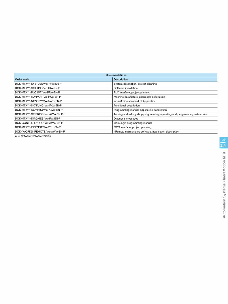
Documentations
Order code Description
DOK-MTX***-SYS*DES*Vxx-PRxx-EN-P System description, project planning
DOK-MTX***-SOFTINS*Vxx-IBxx-EN-P Software installation
DOK-MTX***-PLC*INT*Vxx-PRxx-EN-P PLC interface, project planning
DOK-MTX***-MA*PAR**Vxx-PAxx-EN-P Machine parameters, parameter description
DOK-MTX***-NC*OP***Vxx-AWxx-EN-P IndraMotion standard NC operation
DOK-MTX***-NC*FUNC*Vxx-FKxx-EN-P Functional description
DOK-MTX***-NC**PRO*Vxx-AWxx-EN-P Programming manual, application description
DOK-MTX***-SF*PROG*Vxx-AWxx-EN-P Turning and milling shop programming, operating and programming instructions
DOK-MTX***-DIAGMES*Vxx-IFxx-EN-P Diagnosis messages
DOK-CONTRL-IL**PRO*Vxx-AWxx-EN-P IndraLogic programming manual
DOK-MTX***-OPC*INT*Vxx-PRxx-EN-P OPC interface, project planning
DOK-IWORKS-IREMOTE*Vxx-AWxx-EN-P I-Remote maintenance software, application description
xx = software/firmware version

40 2.5 Automation Systems • IndraMotion for Metal Forming
IndraMotion for Metal Forming – Individual Automation System for Material TransportIndraMotion for Metal Forming is the modular and scalable system solution for cost effective single-axis and multi-axis applications in belt systems and parallel running separation equipment. Preprogram-med controls, compact control units and intelligent drives with a wide range of rotational and linear motors ensure maximum produc-tivity and highest product quality.
The customized automation design is based on the IndraMotion MLD and IndraMotion MLC system solutions. With its integrated and branch-specific extended technology functions, it is exactly tailored to the requirements of modern production plants. Whether the material to be machined is metal, plastic, paper or wood – IndraMotion for Metal Forming solves any and all synchronization and positioning tasks with cost effective efficiency. To meet the various requirements in your pro-duction plant, IndraMotion for Metal Forming is available in the following versions:
• Single-axis applications with IndraMotion MLD-S
- Roll feeds - Feed straighteners - Flying cut-off - Cross cutter - Unwinder - Straightener
• Multi-axis applications with MLD-M and MLC - Belt systems - Parallel running separation
equipment - Profiling systems - Profiling presses - Zigzag feed
Your benefits• Scalable drive platforms with highly
dynamic motors• Standardized programming tools
according to IEC 61131-3 and PLCopen
• Drive-integrated technical safety system, certified according to EN 954-1, Cat. 3
• Intuitive engineering with the IndraWorks software framework
• Low assembly and installation requirements as well as fast startup through matching and pre-configured system components
• Exact synchronization between press and feeding equipment
• Optional technology and communi-cation interfaces
• Ready technology functions for branch-specific “ready-to-apply” solutions
• Easy incorporation of distributed drive solutions in existing or new control designs
• Easy implementation of process functions
IndraMotion for Metal Forming – modular and scalable system solution for perfect and economic material transport

Aut
omat
ion
Sys
tem
s • I
ndra
Mot
ion
for
Met
al F
orm
ing
41
2.5
Additional information
Automation system IndraMotion MLD Chapter 2.2
Automation system IndraMotion MLC Chapter 2.3
Control hardware IndraControl L Chapter 3.1
Visualization devices, controller-based IndraControl VCP Chapter 3.2
Centralized and distributed input/output modules in IP20 Inline Chapter 3.3
Distributed input/output modules in IP67 Fieldline Chapter 3.4
Drive family IndraDrive IndraDrive and IndraDyn product catalog
Engineering framework IndraWorks Chapter 3.5
Your benefit
Complete, perfect and economicl Innovative function blocks, such as function
libraries, user libraries, technology packages and user programs
l Saving of external peripheral componentsl Longer machine life through reduced
mechanical wear
Whether drive-based or rack-based, whether single-axis or multi-axis application, IndraMotion for Metal Forming is a modular and scalable system that will always provide the proper solution.
Motion-Logicdrive-based
IndraMotion MLD-S
Motion-Logiccontroller-based
Ethernet
PROFIBUS
MLD
IndraControl VIndraControl L
InlineInline
IndraDyn IndraDyn IndraDyn IndraDyn
Inline
IndraDrive IndraDrive
Ethernet
PROFIBUS
Ethernet
Engineering Operation
MLD
IndraControl V
Cross Communication
PROFIBUS
Hydraulics Pneumatics
IndraControl V
DDL
Motion-Logicdrive-based
IndraMotion MLD-M IndraMotion MLC
Ethernet
PROFIBUS
MLD
IndraControl VIndraControl L
InlineInline
IndraDyn IndraDyn IndraDyn IndraDyn
Inline
IndraDrive IndraDrive
Ethernet
PROFIBUS
Ethernet
Engineering Operation
MLD
IndraControl V
Cross Communication
PROFIBUS
Hydraulics Pneumatics
IndraControl V
DDL
Ethernet
PROFIBUS
MLD
IndraControl VIndraControl L
InlineInline
IndraDyn IndraDyn IndraDyn IndraDyn
Inline
IndraDrive IndraDrive
Ethernet
PROFIBUS
Ethernet
Engineering Operation
MLD
IndraControl V
Cross Communication
PROFIBUS
Hydraulics Pneumatics
IndraControl V
DDL

42 2.6 Automation Systems • IndraMotion for Handling
IndraMotion for Handling – Turnkey Automation Solution for All Handling TasksIndraMotion for Handling is the system solution for efficient coor-dination of axis movements in fully automated production. This intelli-gent design is based on uniform control and drive platforms and on international software standards. The precisely matching compo-nents allow you to implement your handling applications in any confi-guration you desire.
The essential highlights of IndraMotion for Handling are: easy operation, teach-ing and programming of time-optimized motion sequences to ensure highest product quality. This turnkey automati-on solution with open-source software facilitates engineering and maximizes the flexibility in your individual appli-cation.
Based on the IndraLogic and IndraMotion MLC systems, this solu-tion has been optimized to meet the requirements of handling, assembly, palletizing and pick-and-place applica-tions as well as of machine tools.
Your benefits• Maximum performance and
functionality through innovative control platform
• Free PLC functionality according to IEC 61131-3
• Open standardized communication interfaces
• Flexible scalability for various HMI devices
• Easy teaching, defining and programming of motion sequences through HMI, PC or PLC
• Turnkey open-source solution with PLC basic program
• Complete PLC library and PLCopen function blocks
• Multiple kinematics for various applications
• Quick expansion and easy connec-tion of I/O and function modules
• Drive-integrated technical safety system, certified according to EN 954-1, Cat. 3
• Intuitive engineering with IndraWorks
IndraMotion for Handling – the perfect automation design for time-optimized multi-axis movements in handling and assembly applications.

Aut
omat
isio
n S
yste
ms
• Ind
raM
otio
n fo
r H
andl
ing
43
2.6
IndraMotion for Handling provides all degrees of freedom for centralized and distributed automation, with numerous options for control and visualization devices.
Additional information
Automation system IndraLogic L Chapter 2.1
Automation system IndraMotion MLC Chapter 2.3
Control hardware IndraControl L Chapter 3.1
Visualization devices, embedded PC IndraControl VEH Chapter 3.2
Visualization devices, controller-based IndraControl VCP, VCH Chapter 3.2
Centralized and distributed input/output modules in IP20 Inline Chapter 3.3
Drive family IndraDrive IndraDrive and IndraDyn product catalog
Engineering framework IndraWorks Chapter 3.5
Your benefit
Turnkey, flexible and efficientl Exact positioning with highest precision accuracyl Easy operation and programmingl Time-optimized motion sequencing for minimum
cycle times
Motion-Logiccontroller-based
IndraMotion MLC
Logiccontroller-based
IndraLogic L
IndraControl L IndraControl L IndraControl VIndraControl V
IndraDyn IndraDyn
IndraDrive
IndraControl V
IndraDrive
Ethernet
Engineering
InlineInline
VAC 30
Esc
VAC 30
Operation
IndraControl L IndraControl L IndraControl VIndraControl V
IndraDyn IndraDyn
IndraDrive
IndraControl V
IndraDrive
Ethernet
Engineering
InlineInline
VAC 30
Esc
VAC 30
Operation

44 2.7 Automation Systems • IndraMotion for Packaging
IndraMotion for Packaging – Flexible Automation Systems for the Food Processing and Packaging IndustriesIndraMotion for Packaging ensures shorter cycle times and quicker format change, with simultaneous increased precision. This system allows you to automate your pro-cesses more easily, flexibly and quickly – covering the entire range from the single machine to the link-ed production system. Scalable control platforms and international software standards allow you to implement your various applica-tions in any configuration you desire.
IndraMotion for Packaging will always provide the technically and economi-cally optimal system solution for your application – according to your control architecture and functional require-ments:
• IndraMotion MLD – for drive-based topologies with up to 8 axes, e.g. for carton erectors, labelers
• IndraMotion MLC – for controller-based topologies with up to 32 axes, e.g. for cartoning systems, vertical tubular bag machines
• IndraMotion MLP – for PC-based topologies with up to 32 axes, e.g. for palletizing machines, pick-and-place applications or flow wrappers
Your benefits• Scalable controls on various
platforms• Integrated motion logic functions,
standardized according to IEC 61131-3 and PLCopen
• Time-saving engineering through process-specific technology functions and comprehensive software libraries
• Wide range of HMI devices and I/O components• Scalable drive platforms with highly
dynamic motors• Flexible through various technology
functions• Intuitive software tools for engineering and operation• Open and scalable architectures
with standardized communication interfaces
• Drive-integrated technical safety system, certified according to EN 954-1, Cat. 3
IndraMotion for Packaging – open and scalable complete solution for suc-cessful automation designs in the food processing and packaging industries.

Aut
omat
ion
Sys
tem
s • I
ndra
Mot
ion
for
Pac
kagi
ng
45
2.7
Additional information
Automation system IndraMotion MLD Chapter 2.2
Automation system IndraMotion MLC Chapter 2.3
Automation system IndraMotion MLP In preparation
Control hardware IndraControl L Chapter 3.1
Visualization devices, high-end industrial PC IndraControl VPP Chapter 3.2
Visualization devices, standard industrial PC IndraControl VSP Chapter 3.2
Visualization devices, controller-based IndraControl VCP Chapter 3.2
Centralized and distributed input/output modules in IP20 Inline Chapter 3.3
Distributed input/output modules in IP67 Fieldline Chapter 3.4
Drive family IndraDrive IndraDrive and IndraDyn product catalog
Engineering framework IndraWorks Chapter 3.5
Your benefits
Flexible, open and intelligentl Universal solution for all types of machinesl Standardized interfaces for use worldwidel Innovative solution for shorter cycle times and
faster format changes
Motion-Logicdrive-based
Motion-Logic PC-based
Motion-Logiccontroller-based
Ethernet
PROFIBUS
MLD
IndraControl V
Inline
IndraDyn
IndraDrive
Engineering
Ethernet
Operation
IndraControl L IndraControl V
IndraDyn
Inline
IndraControl V
IndraDyn
Inline
Ethernet
PROFIBUS
MLD
IndraControl V
Inline
IndraDyn
IndraDrive
Engineering
Ethernet
Operation
IndraControl L IndraControl V
IndraDyn
Inline
IndraControl V
IndraDyn
Inline
Ethernet
PROFIBUS
MLD
IndraControl V
Inline
IndraDyn
IndraDrive
Engineering
Ethernet
Operation
IndraControl L IndraControl V
IndraDyn
Inline
IndraControl V
IndraDyn
Inline
IndraMotion MLD IndraMotion MLC IndraMotion MLP
IndraMotion for Packaging, the flexible automation system with scalable control structure is tailored to perfectly meet the requirements of the food processing and packaging industries.

46 03 Control Components
Control Components – Components, Peripherals and Software

Con
trol
Com
pone
nts
47
3
IndraControl L – Controller-Based Controls
Inline – Cabinet-Mount (IP20) I/O Technology
Fieldline – Machine-Mount (IP67) I/O Technology
Software – Engineering Framework IndraWorks
IndraControl V – Human-Machine Interface (HMI) Devices and Industrial PCs
48
3.1
154
3.5
144
3.4
98
3.3
68
3.2

48 3.1 Control Components • IndraControl L
IndraControl L – Controller-Based Control ComponentsIndraControl L the controller-based platform from Rexroth allows easy and consistent automation for all centralized and distributed architec-tures. This technically and economi-cally optimized control design offers a great number of benefits, both for the machine manufacturer and the end user.
IndraControl L – modular and control-ler-based control hardware allowing any factory automation desired, which will also be reliable in the future.
IndraControl L is the flexibly configur-able hardware platform for open con-trol architectures. Whether you intend to implement a motion-control, a CNC or a PLC application – it is always the same hardware you use. Your applica-tion is only defined by the software. To ensure that it matches your application in the best way possible, our control platform is available in various perfor-mance classes. Its open architecture, in combination with many different function modules, facilitates integra-tion in heterogeneous system topolo-gies. Configurable fieldbus interfaces allows the imigration as master and/or slave, depending on the needs of the system.
• Scalable hardware platform• Standardized communication interfaces • Optional expansion through
function and technology modules• Ideal for centralized and distributed
control topologies• Individually expandable with high-
grade Human-Machine Interface (HMI) components
• Modular I/O units

49
3.1
Con
trol
Com
pone
nts
• Ind
raC
ontr
ol L
IndraControl L – compact control platform
Rexroth IndraControl L is the space-saving control platform for easy DIN-rail mounting, requiring less wiring work. It is available in various performance classes with many expansion options. In combination with our PLC system IndraLogic or our motion-control solution IndraMotion, IndraControl L provides a maximum of flexibility and openness for the most varying system designs.
• Uniform hardware platform for all controller-based Rexroth controls
• Performance and function with flexible scalability
• Individual expansion capability through Human-Machine Interface (HMI) and I/O components
• Quick assembly and installation without any tools
• Open through standardized com-munication interfaces
Your benefit
Scalable, future-proof and flexiblel Individual control platform for any topologyl Standardized communication interfacesl Scalable performance and function
IndraControl L – function modules
A range of function modules (fieldbus interfaces and technologie modules) are available to integrate the IndraControl L into heterogeneous control topologies. The modules use the high-speed system bus to com-municate with the control processor – this ensures that the high requirements for performance and functionality are met. Partitial implementation of functions into the modules reduce the load on the controller CPU. • Easy expansion of the functions of the IndraControl L controls• Many communication and technology interfaces• Flexible combination options• Ergonomic design

50 3.1 Control Components • IndraControl L
IndraControl L10
Technical data IndraControl L10
CPU SH4 compatible
RAM 16 MB
Retentive memory 16 kB
Removable storage medium CF Card/128 MB
Diagnostics Temperature monitoring, watchdog, powerfail
Real-time clock –
Display –
Degree of protection IP20
Dimensions (H x W x D) 121 x 123 x 63 mm
Interfaces
I/O modules Inline interface
Communication interfaces 1 x Ethernet TCP/IP (RJ45, 10/100 Base-T)
Inputs/outputs (digital) 8 DC-isolated inputs (with interrupt capability) 4 DC-isolated outputs
I/O expansion Up to 63 Inline I/O modules with up to 128 I/O (16 bytes)
Function modules –
Power supply
Rated value 24 V DC
Tolerance –15/+20 % (without residual ripple)
Residual ripple ±5 %
Umax 30 V DC
Umin 19.2 V DC
Power consumption from ULS max. 1.25 A
Power consumption from UM + US max. 8 A
Environmental conditions
Ambient temperature (operation) +5 to +55 °C
Ambient temperature (transport/storage) –25 to +70 °C
Relative humidity RH-2; 5 % to 95 % acc. to DIN EN 61131-2, no dewing
Atmospheric pressure (operation) Up to 2,700 m above sea level acc. to DIN 60204
Atmospheric pressure (transport/storage) Up to 3,000 m above sea level acc. to DIN 60204
Mechanical strength
Vibration/shock resistance Tested according to EN 60068-2-6/EN 60068-2-27
EMC immunity Tested according to EN 61000-6-2/EN 61000-6-4/EN 61131-2
Availability
Automation system IndraLogic
Ordering data
Type code Description
CML10.1-NN-110-NB-NNNN-NW IndraControl L10 hardware (in preparation)

51
3.1
Con
trol
Com
pone
nts
• Ind
raC
ontr
ol L
IndraControl L15
Technical data IndraControl L15
CPU SH4-compatible
RAM 16 MB
Retentive memory 16 kB
Removable storage medium CF Card/128 MB
Diagnostics Temperature monitoring, watchdog, powerfail
Real-time clock –
Display –
Degree of protection IP20
Dimensions (H x W x D) 121 x 123 x 63 mm
Interfaces
I/O modules Inline interface
Communication interfaces 1 x Ethernet TCP/IP (RJ45, 10/100 Base-T)
1 x SERCOS III-Easy I/O
Inputs/outputs (digital) 8 DC-isolated inputs (with interrupt capability) 4 DC-isolated outputs
I/O expansion Up to 63 Inline I/O modules with up to 129 I/O (16 bytes)
Function modules –
Power supply
Rated value 24 V DC
Tolerance –15/+20 % (without residual ripple)
Residual ripple ±5 %
Umax 30 V DC
Umin 19.2 V DC
Power consumption from ULS max. 1.25 A
Power consumption from UM + US max. 8 A
Environmental conditions
Ambient temperature (operation) +5 to +55 °C
Ambient temperature (transport/storage) –25 to +70 °C
Relative humidity RH–2; 5 % to 95 % acc. to DIN EN 61131-2, no dewing
Atmospheric pressure (operation) Up to 2,700 m above sea level acc. to DIN 60204
Atmospheric pressure (transport/storage) Up to 3,000 m above sea level acc. to DIN 60204
Mechanical strength
Vibration/shock resistance Tested according to EN 60068-2-6/EN 60068-2-27
EMC immunity Tested according to EN 61000-6-2/EN 61000-6-4/EN 61131-2
Availability
Automation system IndraLogic
Ordering data
Type code Description
CML15.1-NS-110-NB-NNNN-NW IndraControl L15 hardware with SERCOS III-Easy I/O (in preparation)

52 3.1 Control Components • IndraControl L
Technical data IndraControl L20
CPU SH4-compatible
RAM 16 MB
Retentive memory 64 kB
Removable storage medium CF Card/128 MB
Diagnostics Temperature monitoring, watchdog, powerfail
Real-time clock Integrated
Display 1 line, 4 operator keys
Degree of protection IP20
Dimensions (H x W x D) 120 x 175 x 76 mm
Interfaces
I/O modules Inline interface
Communication interfaces
1 x Ethernet TCP/IP (RJ45, 10/100 Base-T)
1 x RS232
1 x PROFIBUS DP-Master/Slave interface
Inputs/outputs (digital) 8 DC-isolated inputs (with interrupt capability), 8 DC-isolated outputs
I/O expansion Up to 63 Inline I/O modules with up to 256 I/O (32 bytes)
Function modules –
Power supply
Rated value 24 V DC
Tolerance –15/+20 % (without residual ripple)
Residual ripple ±5 %
Umax 30 V DC
Umin 19.2 V DC
Power consumption from ULS max. 3 A
Power consumption from UM + US max. 8 A
IndraControl L20

53
3.1
Con
trol
Com
pone
nts
• Ind
raC
ontr
ol L
Environmental conditions
Ambient temperature (operation) +5 to +55 °C
Ambient temperature (transport/storage) –25 to +70 °C
Relative humidity RH–2; 5 % to 95 % acc. to DIN EN 61131-2, no dewing
Atmospheric pressure (operation) Up to 2,700 m above sea level acc. to DIN 60204
Atmospheric pressure (transport/storage) Up to 3,000 m above sea level acc. to DIN 60204
Mechanical strength
Vibration/shock resistance Tested according to EN 60068-2-6/EN 60068-2-27
EMC immunity Tested according to EN 61000-6-2/EN 61000-6-4/EN 61131-2
Availability
Automation system IndraLogic
Ordering data
Type code Description
CML20.1-NN-120-NA-NNNN-NW IndraControl L20 hardware
CML20.1-NP-120-NA-NNNN-NW IndraControl L20 hardware with PROFIBUS interface

54 3.1 Control Components • IndraControl L
Technical data IndraControl L40
CPU x86-compatible, L40.1 266 MHz/L40.2 500 MHz
RAM L40.1 32 MB/L40.2 64 MB
Retentive memory L40.1 64 kB/L40.2 128 kB
Removable storage medium CF Card/128 MB
Real-time clock Integrated
Display 1 line, 4 operator keys
Degree of protection IP20
Dimensions (H x W x D) 120 x 175 x 76 mm
Interfaces
Function modules Yes
I/O modules Inline interface
Communication interfaces (standard)1 x Ethernet TCP/IP (RJ45, 10/100 Base-T)
1 x serial RS232 interface
Communication interfaces (optional)
1 x SERCOS interface
1 x PROFIBUS DP master/slave interface
1 x single-pole ready contact
Inputs/outputs (digital) 8 DC-isolated inputs (with interrupt capability), 8 DC-isolated outputs
I/O expansion Up to 63 Inline I/O modules with up to 512 I/O (64 bytes)
Function modules Up to 4
Power supply
Rated value 24 V DC
Tolerance –15/+20 % (without residual ripple)
Residual ripple ±5 %
Umax 30 V DC
Umin 19.2 V DC
Power consumption from ULS max. 3 A
Power consumption from UM + US max. 8 A
IndraControl L40

55
3.1
Con
trol
Com
pone
nts
• Ind
raC
ontr
ol L
Environmental conditions
Ambient temperature (operation) +5 to +55 °C; if the ambient temperature exceeds 45 °C, the optional fan must be installed
Ambient temperature (transport/storage) –25 to +70 °C
Relative humidity RH–2; 5 to 95 % acc. to DIN EN 61131-2, no dewing
Atmospheric pressure (operation) Up to 2,700 m above sea level acc. to DIN 60204
Atmospheric pressure (transport/storage) Up to 3,000 m above sea level acc. to DIN 60204
Mechanical strength
Vibration/shock resistance Tested according to EN 60068-2-6/EN 60068-2-27
EMC immunity Tested according to EN 61000-6-2/EN 61000-6-4/EN 61131-2
Availability
Automation system IndraLogic, IndraMotion MLC, IndraMotion MTX compact
Ordering data
Type code Description
CML40.1-NP-220-NA-NNNN-NW Hardware IndraControl L40, PROFIBUS interface, 32 MB RAM, 64 kB NvRAM, CPU 266 MHz x86-compatible
CML40.1-SP-220-NA-NNNN-NW Hardware IndraControl L40 with SERCOS interface, PROFIBUS interface, 32 MB RAM, 64 kB NvRAM,
CPU 266 MHz x86-compatible
CML40.2-NP-330-NA-NNNN-NW Hardware IndraControl L40, PROFIBUS interface, 64 MB RAM, 128 kB NvRAM, CPU 500 MHz x86-compatible
CML40.2-SP-330-NA-NNNN-NW Hardware IndraControl L40 with SERCOS interface, PROFIBUS interface, 64 MB RAM, 128 kB NvRAM,
CPU 500 MHz x86-compatible

56 3.1 Control Components • IndraControl L
IndraControl L45
Technical data IndraControl L45
CPU x86-compatible/500 MHz
RAM min. 256 MB
Retentive memory min. 128 kB
Removable storage medium CF Card/128 MB
Real-time clock Integrated
Display 1 line, 4 operator keys
Degree of protection IP20
Dimensions (H x W x D) 120 x 175 x 97.5 mm
Interfaces
Function modules Yes
I/O modules Inline interface
Communication interfaces (standard)1 x Ethernet TCP/IP (RJ45, 10/100 Base-T)
1 x single-pole ready contact
Communication interfaces (optional)
1 x SERCOS III interface (2 x RJ45)
1 x PROFInet I/O master or slave (2 x RJ45)
1 x PROFIBUS DP master or slave interface
1 x EtherNet/IP scanner (master) or adapter (slave) (2 x RJ45)
1 x DeviceNet master or slave
Inputs/outputs (digital)8 DC-isolated inputs
8 DC-isolated outputs
I/O expansion Up to 63 Inline I/O modules with up to 512 I/O (64 bytes)
Function modules Up to 4
Power supply
Rated value 24 V DC
Tolerance –15/+20 % (without residual ripple)
Residual ripple ±5 %
Umax 30 V DC
Umin 19.2 V DC
Power consumption from ULS max. 3 A
Power consumption from UM + US max. 8 A

57
3.1
Con
trol
Com
pone
nts
• Ind
raC
ontr
ol L
Environmental conditions
Ambient temperature (operation) +5 to +55 °C
Ambient temperature (transport/storage) –25 to +70 °C
Relative humidity RH–2; 5 % to 95 % acc. to DIN EN 61131-2, no dewing
Atmospheric pressure (operation) Up to 2,700 m above sea level acc. to DIN 60204
Atmospheric pressure (transport/storage) Up to 3,000 m above sea level acc. to DIN 60204
Mechanical strength
Vibration/shock resistance Tested according to EN 60068-2-6/EN 60068-2-27
EMC immunity Tested according to EN 61000-6-2/EN 61000-6-4/EN 61131-2
Availability
Automation system IndraLogic, IndraMotion MLC, IndraMotion MTX compact
Ordering data
Type code Description
CML45.1-xx-xxx-NA-NNNN-NW IndraControl L45 hardware (in preparation)

58 3.1 Control Components • IndraControl L
Technical data IndraControl L65
CPU x86-compatible/1,000 MHz
RAM min. 512 MB
Retentive memory min. 128 kB
Removable storage medium CF Card/128 MB
Real-time clock Integrated
Display 1 line, 4 operator keys
Degree of protection IP20
Dimensions (H x W x D) 120 x 175 x 97.5 mm
Interfaces
Function modules Yes
I/O modules Inline interface
Communication interfaces (standard)1 x Ethernet TCP/IP (RJ45, 10/100 Base-T)
1 x single-pole ready contact
Communication interfaces (optional)
1 x SERCOS III interface (2 x RJ45)
1 x PROFInet I/O master or slave (2 x RJ45)
1 x PROFIBUS DP master or slave interface
1 x EtherNet/IP scanner (master) or adapter (slave) (2 x RJ45)
1 x DeviceNet master or slave
Inputs/outputs (digital)8 DC-isolated inputs
8 DC-isolated outputs
I/O expansion Up to 63 Inline I/O modules with up to 512 I/O (64 bytes)
Function modules Up to 4
Power supply
Rated value 24 V DC
Tolerance –15/+20 % (without residual ripple)
Residual ripple ±5 %
Umax 30 V DC
Umin 19.2 V DC
Power consumption from ULS max. 3 A
Power consumption from UM + US max. 8 A
IndraControl L65

59
3.1
Con
trol
Com
pone
nts
• Ind
raC
ontr
ol L
Environmental conditions
Ambient temperature (operation) +5 to +55 °C
Ambient temperature (transport/storage) –25 to +70 °C
Relative humidity RH–2; 5 % to 95 % acc. to DIN EN 61131-2, no dewing
Atmospheric pressure (operation) Up to 2,700 m above sea level acc. to DIN 60204
Atmospheric pressure (transport/storage) Up to 3,000 m above sea level acc. to DIN 60204
Mechanical strength
Vibration/shock resistance Tested according to EN 60068-2-6/EN 60068-2-27
EMC immunity Tested according to EN 61000-6-2/EN 61000-6-4/EN 61131-2
Availability
Automation system IndraLogic, IndraMotion MLC
Ordering data
Type code Description
CML65.1-xx-xxx-NA-NNNN-NW IndraControl L65 hardware (in preparation)

60 3.1 Control Components • IndraControl L
PROFIBUS DP master
Additional PROFIBUS DP master communication interface
DeviceNet master
Communication interface DeviceNet master
Cross-communication
Cross-communication module for IndraControl L
For implementation of high-speed data exchange between motion-control controls, based on SERCOS interface with Fiber Optics
IndraControl L – Function Modules
SERCOS III
Communication interface SERCOS III
For implementation of the Ethernet-based real-time communication interface SERCOS III, as interface to drives and I/O peripherals

61
3.1
Con
trol
Com
pone
nts
• Ind
raC
ontr
ol L
Cam controller
Function interface, cam controller with 16 high- speed outputs
For implementation of high-speed cams for motion- control applications
SRAM module
Memory module with 8 Mbytes SRAM, battery-buffered
For implementation of additional storage capacity for CNC and motion-control applications
Fast I/O
Function interface, high-speed inputs and outputs for short reaction times
For implementation of I/O with very short reaction times; 8 inputs, 8 outputs and 8 user configurable inputs or outputs
Master axis encoder
1 x EnDat interface (in preparation)

62 3.1 Control Components • IndraControl L
IndraControl L – Function Modules
Technical data PROFIBUS DP master DeviceNet master SERCOS III Cross-communication
Degree of protection IP20 IP20 IP20 IP20
Dimensions (H x W x D) mm 120 x 20 x 70 120 x 20 x 70 120 x 20 x 70 120 x 20 x 70
Adjustable ring cycle time ms – – – 2, 4, 8
max. number of slaves – – – 15, 31, 63
Power supply
Internal System bus System bus System bus System bus
Internal power consumption W 1.65 1.4 2.05 2.3
External V DC – 24 (DeviceNet voltage) – –
External power consumption W – 1.4 – –
Environmental conditions
Ambient temperature (operation) °C +5 to +55
Ambient temperature
(transport/storage)°C –25 to +70
Relative humidity RH–2; 5 % to 95 % acc. to DIN EN 61131-2, no dewing
Atmospheric pressure (operation) Up to 2,700 m above sea level acc. to DIN 60204
Atmospheric pressure
(transport/storage)Up to 3,000 m above sea level acc. to DIN 60204
Mechanical strength
Vibration/shock resistance Tested according to EN 60068-2-6, EN 60068-2-27
EMC immunity Tested according to EN 61000-6-2, EN 61000-6-4
Availability
Automation systemIndraMotion MLC,
IndraLogic
IndraMotion MLC,
IndraLogic, IndraMotion MTXIndraMotion MLC IndraMotion MLC
Type code CFL01.1-P1 CFL01.1-V1 CFL01.1-R3 CFL01.1-Q2

63
3.1
Con
trol
Com
pone
nts
• Ind
raC
ontr
ol L
Technical data Cam controller Fast I/O SRAM
Degree of protection IP20 IP20 IP20
Dimensions (H x W x D) mm 120 x 20 x 70 120 x 20 x 70 120 x 20 x 70
Memory MB – – 8 (SRAM)
Buffer time – – min. 4 years
Battery type – –CR2450 3 V Lithium battery
(CAP01.1-B2)
Power supply
Internal System bus System bus System bus
Internal power consumption W 2.8 0.3 1.0
External V DC 24 24 –
Tolerance (without residual ripple) % –15/+20 –15/+20 –
Residual ripple % ±5 ±5 –
Umax V 30 30 –
Umin V 19.2 19.2 –
Power consumption (max.) A 4 4 –
Digital inputs
Number –max. 16 (of which 8 are fixed and 8 can
be bitwise configured as input or output)–
Connection method – 1-wire –
Potential isolated from logic voltage – Yes –
Reverse polarity protection – Yes –
Input voltage at “0”/”1” V DC – –3 to +5/+11 to +30 –
Sensor supply V DC – 24 –
Digital outputs
Number 16 max. 16 (of which 8 are fixed and 8 can
be bitwise configured as input or output)–
Connection method 1-wire 1-wire –
Output type Semiconductor, no retaining Semiconductor, no retaining –
Output voltage, nominal value V 24 24 –
Rated output current A 0.5 0.5 –
Lamp load at 8 Hz W 5 5 –
Inductive load at 1 Hz W 6.2 (SG 1) 6.2 (SG 1) –
Environmental conditions
Ambient temperature (operation) °C +5 to +55
Ambient temperature
(transport/storage)°C –25 to +70
Relative humidity RH–2; 5 % to 95 % acc. to DIN EN 61131-2, no dewing
Atmospheric pressure (operation) Up to 2,700 m above sea level acc. to DIN 60204
Atmospheric pressure
(transport/storage)Up to 3,000 m above sea level acc. to DIN 60204
Mechanical strength
Vibration/shock resistance Tested according to EN 60068-2-6, EN 60068-2-27
EMC immunity Tested according to EN 61000-6-2, EN 61000-6-4
Availability
Automation system IndraMotion MLC IndraMotion MLC IndraMotion MLC, IndraMotion MTX
Type code CFL01.1-N1 CFL01.1-E2 CFL01.1-Y1
Note: The various function modules are not entirely supported by every system. For information on which function modules are supported by the system version used, please refer to the appropriate system-specific manual.

64 3.1 Control Components • IndraControl L
Ordering data
Type code Description
Fieldbus interfaces
CFL01.1-P1 PROFIBUS DP master
CFL01.1-V1 DeviceNet master
Communication interfaces
CFL01.1-R3 SERCOS III
CFL01.1-Q2 Cross-communication (SERCOS interface with FO)
Function interfaces
CFL01.1-N1 Cam controller with 16 high-speed outputs
CFL01.1-E2 High-speed inputs/outputs, 8 inputs, 8 outputs, 8 freely configurable I/O
CFL01.1-Y1 8 Mbyte SRAM, battery-buffered
CFL01.1-G1 (in preparation) Master axis encoder interface, 1 x EnDat interface
Additional accessories
CAL01.1-F1 Fan
CAP01.1-B2 Spare battery for SRAM module CFL01.1-Y1
R-IB IL CML S01-PLSET Connector set for IndraControl L20, L40, L45, L65
R-IB IL FIELD 2 Labeling field, narrow
R-IB IL FIELD 8 Labeling field, wide
I/O expansion
See Inline modules Chapter 3.3
Ethernet cable sets
RKB0007 Crosslink Cat 5; 2-pair, shielded, RJ45/IP20, RJ45/IP20
RKB0008 Patch cable Cat 5; 2-pair, shielded, RJ45/IP20, RJ45/IP20
RS232 cable sets
RKB0009 RS232 cable, D-SUB, D-SUB
Documentations
Type code Description
DOK-CONTRL-IC*L40*****-PRxx-EN-P Project planning for IndraControl L40 and L40 with SERCOS interface
DOK-CONTRL-IC*L20*****-PRxx-EN-P Project planning for IndraControl L20
Advanced documentations
DOK-CONTRL-R-IL*PBSSYS-AWxx-EN-P Inline PROFIBUS DP, application description
DOK-CONTRL-R-IL*PB*-BK-FKxx-EN-P Inline PROFIBUS DP terminal and module supply, functional description
xx = software/firmware version
IndraControl L – Function Modules

65
3.1
Con
trol
Com
pone
nts
• Ind
raC
ontr
ol L

66 3.1 Control Components • IndraControl L
IndraControl L10, L15 and L20
IndraControl L20
175.4 75.9
126.
7123 63
121
IndraControl L10 and L15
IndraControl L20
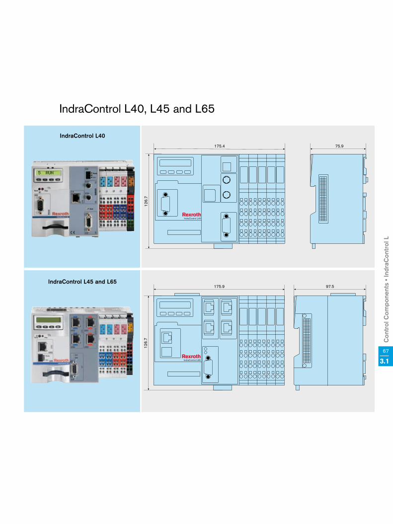
Con
trol
Com
pone
nts
• Ind
raC
ontr
ol L
67
3.1
IndraControl L40, L45 and L65
IndraControl L40
175.4 75.912
6.7
IndraControl L40
175.4 75.9
126.
7
IndraControl L65
175.9 97.5
126.
7
IndraControl L65
175.9 97.5
126.
7
IndraControl L40
IndraControl L45 and L65

68 3.2 Control Components • IndraControl V
Rexroth IndraControl V is the com-prehensive HMI system range for individual control, operation and visualization in all industries. The program range covers controller-based devices, compact embedded PCs and high-performance industri-al PCs. With its scalable hardware and software, IndraControl V can be precisely adapted to your machine-specific requirements.
IndraControl V – the comprehensive product range for individual control, operation and visualization in all industries.
IndraControl V – Trend-Setting Human-Machine Interface (HMI) Devices and Industrial PCs
IndraControl V integrates all functions required for cost effective automation – from convenient operation and clear-ly organized visualization to integrated controls and diagnostics. When com-bined with the proven system solutions from Rexroth, IndraControl V provides you with a complete automation solu-tion for:
• Machine tools• Transfer machines• Printing presses and processing machines• Food processing and packaging machines• Forming machines• Wood processing machines• Textile machines• Handling and assembly systems
IndraControl V is available in the following versions:
• Controller-based - IndraControl VCP - IndraControl VCH
• Embedded-PC-based - IndraControl VEP - IndraControl VEH
• PC-based - IndraControl VSP - IndraControl VPP - IndraControl VDP - IndraControl VPB - IndraControl VSB
• Additional components - IndraControl VAK - IndraControl VAM

Con
trol
Com
pone
nts
• Ind
raC
ontr
ol V
69
3.2
IndraControl VCP – controller-based compact operator terminals
These controller-based compact oper-ator terminals allow you to edit your production data simply by pressing a key or touching the screen. The system versions cover a range from simple small graphics displays to touchscreens with full graphics capa-bilities – with the number of function keys depending on the system design. The comprehensive interface range fulfills almost all of your com-munication wishes, whether Ethernet, fieldbus or serial.
• Inexpensive operation and visualization
• Compact dimensions • Easy configuration of the system
visualization• Comprehensive functions with the
visualization software VI-Composer• Support of Asian characters sets
IndraControl VEP – embedded-PC-based operator terminals
These terminals allow you to operate your machine easily and conveniently via a touchscreen or a virtual key-board. These “almost a PC” devices only use embedded components to maximize reliability. Through the multi-tude of interfaces and slots, the IndraControl VEP devices can be optimally adapted to comply with machine and system requirements. This flexibility allows you to use the devices only for visualization, or to expand them with our soft PLC solution IndraLogic.
• Compact system design for attachment in control cabinet or to pendants
• Hardware without hard disk or rotating media
• Control and visualization in a single device
• Integrated short-time UPS• Visualization, operation and observa-
tion with the common WinStudio visualization software
IndraControl VCH – compact manual operator panel for mobile use
Irrespective of the particular location – IndraControl VCH 08 allows operation, setup, parameterization and diagnos-tics via Ethernet TCP/IP. During connection and disconnection, the stop function is overridden automati-cally, thus ensuring smooth work. Together with the optimal design, the low weight allows fatigue-free work and high operator convenience. The integrated 3-step enabling button and the 2-circuit stop button are looped in through the junction box VAC 30, thus ensuring maximum safety. • Safety functions for man and
machine • Handles with integrated enabling
and stop buttons • Sturdy structure for industrial use • Optimum ergonomics for reliable
fatigue-free handling • Brilliant 3.8“ graphics display and
universal-use touch panel for con-venient operation and visualization
Your benefit
Versatile, sturdy and modularl Consistent range for control, operation and
visualizationl Reliable system technology, even in hostile
industrial environmentsl Reliable in the future through modern
PC technology

70 3.2 Control Components • IndraControl V
IndraControl VPP – PC solution for high-end industrial requirements
Owing to their mechanic and electric design, the compact PC operator terminals IndraControl VPP are designed for use in extreme industrial environments. They are specifically characterized by an integrated UPS and a shock-mounted hard disk. The optimized cooling system and temper-ature monitoring unit additionally ensure highest reliability. The devices and software packages, which are available for an extended time, offer maximum investment protection in the design and production of your machines.
• Best industry compatibility through the use of reliable hardware com-ponents
• Vibration resistance up to 1 g during operation
• Shock loading capacity up to 15 g• Low heat losses through optimized
cooling system• Components, such as processors,
motherboards, etc. available over the long term
• Complete traceability of all modifi-cations over the entire service life
• Ensured service capability, at least 5 years
IndraControl VSP – cost-effective PC technology for industrial use
The operator terminals of the IndraControl VSP series integrate PC, operator and visualization to form one compact unit. This device allows you to control, operate and visualize single machines or stations and even com-plex production lines – economically and with maximum transparency in your production. This makes IndraControl VSP the ideal platform for all tasks in PC-based automation.
• Highest performance through latest PC technology
• High investment protection through standardized hardware and software
• Open and flexible for customer- specific solutions
• High production reliability through EMC-certified design
• Operator- and service-friendly system construction
• Complete traceability of all modifica-tions over the entire service life
• Ensured service capability, at least 3 years
IndraControl VEH – manual operator panel for mobile use
Irrespective of the particular location – IndraControl VEH 30 allows operation, setup, parameterization and diagnos-tics via Ethernet TCP/IP. The hot-plug principle facilitates trouble-free con-nection and disconnection during run-ning operation, while the stop function is reliably overridden. To ensure fatigue-free handling, highest operator conve-nience and ergonomics were the key factors in the design development. The integrated 3-step enabling button and the 2-circuit stop button are looped in through the junction box VAC 30, thus ensuring maximum safety. • Flexible use through hot-plug
principle • Safety functions for man and
machine• Handles with integrated enabling
and stop buttons• Sturdy structure for industrial use• Optimum ergonomics for reliable
fatigue-free handling• Brilliant 8.4“ touchscreen for conven-
ient operation and visualization

Con
trol
Com
pone
nts
• Ind
raC
ontr
ol V
71
3.2
IndraControl VSB, VPB and VDP – ideal PC solution for distributed architecture
IndraControl VSB, VPB and VDP pro-vide a professional solution for appli-cations where PC and control unit have to be separated. While the indus-trial PC is safely kept in the control cabinet, the sturdy and extremely thin operator display can be attached directly to the machine. To meet vari-ous industrial requirements, both the PCs and the displays are available in different versions.
• Cost-effective cabinet PC (VSB) with latest technology for standard applications
• Extreme duty cabinet PC (VPB) with special hardware for hostile industri-al environments
• Thin displays (VDP), with optional keys or touchscreen
• Open and flexible for customer- specific requirements
• Individual solution for distributed operating and control designs
The compact industrial keyboards and the comfortable machine control panels allow you to configure a perfect and individual control and visualization design of your machine. These addition-al components are precisely matched to our IndraControl V devices and, with the industry-compatible design, ensure reliable and safe operation.
Slide-out keyboards VAK • Alphanumeric keyboard and
integrated mouse• Protection to IP65 both
when closed and when open
Touch panels VAK • Robust complete keyboard with
configurable keys and separate number pad
• Protection to IP65 • Low installation depth
Machine control panels VAM • Optimized control design for
standard machine tools and automated production
• Protection to IP54
IndraControl VAK and VAM – ergonomic industrial keyboards and machine control panels
IndraControl VPP 21 – complete PC control units for pendant mounting
IndraControl VPP 21 integrates PC, control, visualization and operating elements in a single ergonomic housing. Precisely matching compo-nents, minimized weight and passive cooling design optimize this control unit for pendant mounting. All inter-faces for control, programming and networking are already on board. For various applications, it is available with touchscreen or with integrated machine control panel.
• Complete solution for control, operation and visualization
• Optimized cooling system for maintenance-free use
• Start, stop and E-stop buttons already integrated
• Large brilliant 14“ display• Operator- and service-friendly
structure• Internal buffering of retentive data

72 3.2 Control Components • IndraControl V
IndraControl VCP
Technical data VCP 02 VCP 05 VCP 08 VCP 11 VCP 20 VCP 25
Display
FSTN FSTN-touch FSTN STN-color touch
With graphics capabilityWith full graphics
capability
5 grey tones 125 colors
3.0“ 3.0“ 3.8“ 3.8“ 5.7“ 5.7“
Resolution 160 x 80 160 x 80 320 x 240 320 x 240 320 x 240 320 x 240, 1/4 VGA
Keyboard/touch Membrane keys Touchscreen Membrane keys Touchscreen
Function keys/
system keys
4/
7 (2 with LED)
6/
24 (3 with LED)
15 (12 with LED)/
22 (3 with LED)–
16 (8 with LED)/
8–
Application memory 3 MB
Flash memory 16 MB
Slot for expansions 1
Line voltage 24 V DC
Interfaces 1 x Ethernet, 2 x USB host, optional: 1 RS232/RS485 module
Fieldbus PROFIBUS DP slave, DeviceNet (optional)
Approvals CE/UL/CSA
Front protection degree IP65
Temperature 5 to 45 °C
Dimensions (W x H x D) 144 x 96 x 58 mm 120 x 168 x 55 mm 155 x 205 x 55 mm 130 x 96 x 55 mm 300 x 160 x 55 mm 203 x 147 x 66 mm
Availability
Automation system IndraMotion MLD, IndraMotion MLC, IndraMotion MTX, IndraLogic (technical details available on request)

Con
trol
Com
pone
nts
• Ind
raC
ontr
ol V
73
3.2
IndraControl VCP 02
144
3.0”
58
96
IndraControl VCP 02
144
3.0”
58
96
IndraControl VCP 05
168
120
3.0”
55
IndraControl VCP 05
168
120
3.0”
55
IndraControl VCP 02 and VCP 05
IndraControl VCP 02
IndraControl VCP 05

74 3.2 Control Components • IndraControl V
IndraControl VCP 08 and VCP 11
IndraControl VCP 11
130
3.8”
55
96
IndraControl VCP 08
IndraControl VCP 11
IndraControl VCP 08
155
3.8”
55
205
IndraControl VCP 11
130
3.8”
55
96

Con
trol
Com
pone
nts
• Ind
raC
ontr
ol V
75
3.2
IndraControl VCP 20 and VCP 25
IndraControl VCP 20
300
5,7”
5516
0
55
203 66
147
IndraControl VCP 25
5.7”
IndraControl VCP 20
300
5,7”
5516
0
55
IndraControl VCP 20
IndraControl VCP 25

76 3.2 Control Components • IndraControl V
Technical data VCH 08
Display 3,8" grey tones
Resolution 320 x 240
Touchscreen –
Keyboard 40 membrane keys
Function keys 18 freely definable function keys
Stop button l
Enabling button 2 two-circuit, three-step buttons
Override potentiometer °
Handwheel °
Processor XScale
RAM 64 MB
Compact flash 64 MB
Line voltage 24 V DC
Human-Machine Interface (HMI) VI-Composer
Approvals UL 508, UL 1740, SIBE
Degree of protection IP65
Temperature 5 – 45 °C
Dimensions (W x H x D) Diameter 250 x 55 & 37 handle
Weight 1.1 kg
Max. height of fall 1.5 m
Cable length 8 m
Availability
Automation system IndraMotion MLD, IndraMotion MLC, IndraMotion MTX, IndraLogic (technical details available on request)
Accessories
Connection unit VAC 30 (interfaces: RJ45, Ethernet, terminals for stop and enabling buttons)
Wall-mounted holder VAS 01.1-002
l Default° Optional
IndraControl VCH

Con
trol
Com
pone
nts
• Ind
raC
ontr
ol V
77
3.2
IndraControl VCH 08
252
3.8”
114
IndraControl VCH 08

78 3.2 Control Components • IndraControl V
IndraControl VEP
Technical data VEP 30 VEP 40 VEP 50 VEP 30 CG
Display 8.4" TFT 12.1" TFT 15" TFT 8.4" TFT
Resolution 800 x 600, SVGA 800 x 600, SVGA 1,024 x 768, XGA 800 x 600, SVGA
Touch screen l
KeyboardThrough virtual keyboard
– 5 additional keys
Processor Celeron 400 MHz
RAM 128 MB
Compact flash 128 MB
Module slots 2 1
Line voltage 24 V DC
Interfaces RS232, VGA, PS/2, 2 x USB, Ethernet
Fieldbus Fieldbus module (PROFIBUS DP master) occupies 1 slot
UPS Short-time UPS for data backup (512 kB) to compact flash
Operating system Windows CE
Approvals CE/UL/CSA
Front protection degree IP65 Front IP64/overall IP40
Temperature 5 to 45 °C
Dimensions of 1 slot (W x H x D) 296 x 200 x 72 mm 350 x 290 x 78 mm 407 x 370 x 82 mm 306 x 241 x 90 mm
Dimensions of 2 slots (W x H x D) 296 x 200 x 92 mm 350 x 290 x 98 mm 407 x 370 x 103 mm –
Availability
Automation system IndraMotion MLC, IndraMotion MTX, IndraLogic (technical details available on request)
Accessories
Keybord expansion – VAS 02
l Default

Con
trol
Com
pone
nts
• Ind
raC
ontr
ol V
79
3.2
306 93
242
8.4"
296 92.520
0 8,4"
IndraControl VEP 30 and VEP 30CG
306 93
242
8,4"
IndraControl VEP 30
IndraControl VEP 30CG

80 3.2 Control Components • IndraControl V
IndraControl VEP 40 and VEP 50
350 83.3
290
12.1"
407 87
370 15.0"
350 83.3
290
12.1"
IndraControl VEP 40
IndraControl VEP 50

Con
trol
Com
pone
nts
• Ind
raC
ontr
ol V
81
3.2

82 3.2 Control Components • IndraControl V
IndraControl VEH
Technical data VEH 30
Display 8.4" TFT
Resolution 800 x 600 SVGA
Touchscreen l
Keyboard Through virtual keyboard
Function keys 34 membrane keys: 2 x 6 jog keys; 2 x 8 free definable; 4 navigation keys; 1 x OK key; 1 x ESC key
Stop button 2-circuit button
Enabling button 2 two-circuit, three-step buttons (optional)
Override potentiometer °
Handwheel °
Processor 300 MHz, Intel-based
RAM 128 MB
Compact flash 128 MB
Line voltage 24 V DC
Operating system Windows CE
Approvals CE/UL/CSA/BG approval
Degree of protection IP65
Temperature 5 to 45 °C
Dimensions (W x H x D) 240 x 250 x 80 + 55 mm handle
Weight 1.6 kg
Max. height of fall 1 m
Cable length 8 m
Availability
Automation system IndraMotion MLC, IndraMotion MTX, IndraLogic (technical details available on request)
Accessories Connection unit Wall-mounted holder
VAC 30 VAS 01
InterfacesRJ45, Ethernet, series terminals
for stop and enabling buttons
l Default° Optional

Con
trol
Com
pone
nts
• Ind
raC
ontr
ol V
83
3.2
IndraControl VEH30
240 134.3
250
8.4"
IndraControl VEH

84 3.2 Control Components • IndraControl V
IndraControl VSP
Technical data VSP 16 VSP 16 VSP 40 VSP 40
Display 12" TFT 15" TFT
Resolution 800 x 600, SVGA 1,024 x 768, XGA
Touchscreen l – l –
Machine/function/additional keys – 16/16/14 – 16/16/14
Alphanumeric keyboard Additional components VAK
Front USB
(protection degree IP65)1
Processor/RAM Celeron 2 GHz/512 MB
Slots (PCI/combined) 6/0
Line voltage 90 – 264 V AC, alternatively 24 V DC
Hard disk > 30 GB l
DVD-ROM/DVD-RW °
Interfaces PS/2 mouse, PS/2 keyboard, VGA, LPT, COM, 2 x USB (2.0), 1 x Ethernet
Status LED Voltage, hard disk
UPS External
Operating system Windows XP
Approvals CE/UL/CSA
Front protection degree IP65
Vibration/shock 0.25 g/5 g
Temperature 5 to 45 °C
Dimensions (W x H x D) 350 x 290 x 210 mm 350 x 290 x 210 mm 407 x 370 x 210 mm 407 x 370 x 210 mm
Availability
Automation system IndraMotion MLC, IndraMotion MTX, IndraLogic (technical details available on request)
l Basic equipment° Optional

Con
trol
Com
pone
nts
• Ind
raC
ontr
ol V
85
3.2
IndraControl VSP 16 and VSP 40
IndraControl VSP 16
12.1"
350 217.5 17
290
IndraControl VSP 40
15"
407 215.6 17
370
IndraControl VSP 16
12.1"
350 217.5 1729
0
IndraControl VSP 16
IndraControl VSP 40

86 3.2 Control Components • IndraControl V
IndraControl VPP
Technical data VPP 16 VPP 16 VPP 40 VPP 40
Display 12" TFT 15" TFT
Resolution 800 x 600, SVGA 1,024 x 768, SVGA
Touchscreen l – l –
Machine/function/additional keys – 16/16/14 – 16/16/14
Alphanumeric keyboard Additional components VAK
Front USB (protection degree IP65) 1
Processor/RAM Celeron M 1.3 GHz/at least 512 MB
Slots (PCI/combined) 2/1 or 3/1
Line voltage 85 – 264 V AC, alternatively 24 V DC
Hard disk > 20 GB, vibration-damped l
DVD-ROM/DVD-RW °
Interfaces PS/2 mouse, PS/2 keyboard, VGA, LPT, COM, 2 x USB, 1 x Ethernet
UPS Integrated electronics, external battery
Monitoring software Voltage, UPS battery voltage, temperature and fan
Status LED Voltage, hard disk, UPS and temperature
Operating system Windows XP
Approvals CE/UL/CSA
Front protection degree IP65
Vibration/shock 1 g/15 g
Temperature 5 to 45 ° C
Dimensions of 3 slots (W x H x D) 350 x 290 x 146 mm 350 x 290 x 146 mm 407 x 370 x 146 mm 407 x 370 x 146 mm
Dimensions of 4 slots (W x H x D) 350 x 290 x 166 mm 350 x 290 x 166 mm 407 x 370 x 166 mm 407 x 370 x 166 mm
Availability
Automation system IndraMotion MLC, IndraMotion MTX, IndraLogic (technical details available on request)
l Default° Optional

Con
trol
Com
pone
nts
• Ind
raC
ontr
ol V
87
3.2
IndraControl VPP 16 and VPP 40
350 158.2 17
290 12"
IndraControl VPP 10
407 156 17
370 15"
IndraControl VPP 40
350 158.2 17
290 12"
IndraControl VPP 10
407 156 17
370 15"
IndraControl VPP 40
IndraControl VPP 16
IndraControl VPP 40

88 3.2 Control Components • IndraControl V
IndraControl VPP 21
Technical data VPP 21 VPP 21
Display 14.1" TFT
Resolution 1,024 x 768, XGA
Touchscreen l –
Machine/function/additional keys
3 pushbuttons (start, stop, E-stop)
/-/
6 navigation keys
3 pushbuttons (start, stop, E-stop)
/12 function buttons/
6 navigation, 16 operating, 8 special keys,
numeric block, cursor keys with button mouse
Processor/RAM Pentium III 700 MHz/512 MB
Slots (PCI) 1
Line voltage 24 V DC
Hard disk > 20 GB l
Compact flash, external °
Interfaces PS/2 mouse, PS/2 keyboard, VGA, LPT, COM, 1 x USB, 2 x Ethernet
Fieldbus master PROFIBUS DP
UPS External
Monitoring functions Status LED, PC box: voltage, hard disk, battery SRAM and temperature
Operating system Windows XP
Approvals CE/UL/CSA
Degree of protection (front/overall) IP64/40
Vibration/shock 0.25 g/5 g
Temperature 5 to 45° C
Dimensions (W x H x D) 402 x 302 x 140 mm 402 x 468 x 140 mm
Availability
Automation system IndraMotion MLC, IndraMotion MTX, IndraLogic (technical details available on request)
l Default° Optional

Con
trol
Com
pone
nts
• Ind
raC
ontr
ol V
89
3.2
IndraControl VPP 21
14.1"
458
402 140 24
INFO
IndraControl VPP 21
14.1"302
402 140 24
IndraControl VPP 21
14.1"
458
402 140 24
INFO
IndraControl VPP 21
14.1"302
402 140 24
IndraControl VPP 21
IndraControl VPP 21

90 3.2 Control Components • IndraControl V
IndraControl VSB, VPB and VDP
Technical data VSB 40 VPB 40 VDP 16 VDP 40
Display – 12" TFT 15" TFT
Resolution – 800 x 600, SVGA 1,024 x 768, SVGA
Touchscreen – l
Machine/function/additional keys – As alternative for touch 16/16/14
Alphanumeric keyboard – Additional components VAK
Front USB (protection degree IP65) – 1
Processor/RAM Celeron 2 GHz/512 MB Celeron 1.3 GHz/512 MB –
Slots (PCI/combined) 6/0 2/1 or 3/1 –
Line voltage 90 to 264 V AC 85 to 264 V AC Via VPB/VSB
Line voltage, alternative – 24 V DC –
Hard disk > 30 GB, permanently installed l – –
Hard disk > 20 GB, vibration-damped ° l –
DVD-ROM/DVD-RW ° –
InterfacesPS/2 mouse, PS/2 keyboard, VGA, LPT, COM,
2 x USB, 1 x Ethernet
PS/2 mouse, PS/2 keyboard, 4 x USB,
PROFIBUS DP slave machine keys (optional)
PC-VDP connection G4 G1/G3/G4 G4
UPS ExternalIntegrated electronics,
external battery–
Status LED –Voltage HDD,
UPS, temperatureDisplay of all LEDs same as with VPP/VSP
Operating system Windows XP –
Approvals CE/UL/CSA CE/UL/CSA
Degree of protection IP20 Front IP65
Vibration/shock 0.25 g/5 g 1 g/15 g 1 g/15 g
Temperature 5 to 45° C 5 to 45 °C
Dimensions (W x H x D) See below See below 350 x 290 x 65 mm 407 x 370 x 69 mm
Dimensions, 3 slots – 364 x 130 x 214 mm –
Dimensions, 4 slots – 364 x 130 x 214 mm –
Dimensions, 6 slots 360 x 260 x 190 mm – –
Availability
Automation system IndraMotion MLC, IndraMotion MTX, IndraLogic (technical details available on request)
l Default° Optional

Con
trol
Com
pone
nts
• Ind
raC
ontr
ol V
91
3.2
IndraControl VSB 40 and VPB 40
130
364 235.7
262 363.8
190
262 363.8
190
IndraControl VSB 40
IndraControl VPB 40

92 3.2 Control Components • IndraControl V
IndraControl VDP 16 and VDP 40
12"
350 69.5 17
290
IndraControl VDP 16
IndraControl VDP 40
407 73.5 17
370 15"
12"
350 69.5 1729
0
IndraControl VDP 16
IndraControl VDP 40
407 73.5 17
370 15"
IndraControl VDP 16
IndraControl VDP 40

Con
trol
Com
pone
nts
• Ind
raC
ontr
ol V
93
3.2

94 3.2 Control Components • IndraControl V
IndraControl VAK and VAM
Technical data VAK 10/40 VAK 11/41 VAM 10/40 VAM 11/41
TypeSlide-out keyboard
(full keyboard)
Touch panel
(full keyboard)
Machine control panel for
standard machine tools
Machine control panel for
automated production
Keyboard Short-stroke keys –
Function and additional keys86 keys, alphanumeric block,
integrated mouse pointer
106 keys, alphanumeric block,
4 variable keys, keyboard mouse– –
Illuminated pushbutton – 2 x 15 short-stroke buttons 3 x 5 short-stroke buttons
E-stop pushbutton – – 2 break contacts
Override – Feed and spindle
Flexible module field – VAM 40 VAM 41
Key switch – 4-step switch with forced and DC-isolated contacts
Pre-cutouts, 22.5 mm
in diameter– – 7 ea/8 ea
Fieldbus – PROFIBUS DP slave
Logic supply UL – 24 V DC (19.2 ... 30 V), PELV
Power consumption from UL – max. 0.5
Input/output supply UQ – 24 V DC (19.2 ... 30 V), PELV
Power consumption 0.01 A 0.01 A max. 1.7 A max. 1.7 A
Line voltage 5 V DC (via PS/2) 24 V DC
Interface PS/2 Interface for external handwheel, 16/8 digital I/O, 24 V DC
Approvals CE/UL/CSA
Front protection degree IP65 IP54
Temperature 5 to 45 °C
Dimensions (W x H x D) 350/407 x 88 x 200 mm 350/407 x 140 x 40 mm 350/407 x 169 x 102 mm 350/407 x 210 x 102 mm
Panel cutout (W x H) 324 x 58/376 x 58 mm 318 x 108/375 x 108 mm 318 x 137/375 x 137 mm 318 x 178/375 x 178 mm
Power cord 1 m –
Weight in kg typ. 2.5/2.6 typ. 1.3/1.4 typ. 1.17/1.38 typ. 1.17/1.38
Color Light grey RAL 7035
Availability
Automation system IndraMotion MLC, IndraMotion MTX, IndraLogic (technical details available on request)

Con
trol
Com
pone
nts
• Ind
raC
ontr
ol V
95
3.2
IndraControl VAK 10, VAK 11, VAK 40 and VAK 41
88VAK 10: 350VAK 40: 407 211.5 19
140
VAK 11: 350VAK 41: 407 34
VAK 11
IndraControl VAK 10, VAK 40
IndraControl VAK 11, VAK 41

96 3.2 Control Components • IndraControl V
IndraControl VAM 10 and VAM 40
VAM 10
169
350 63 39
VAM 40
169
407 63 39
IndraControl VAM 10
IndraControl VAM 40

Con
trol
Com
pone
nts
• Ind
raC
ontr
ol V
97
3.2
IndraControl VAM 11 and VAM 41
VAM 41
210
407 63 39
VAM 11
210
350 63 39IndraControl VAM 11
IndraControl VAM 41
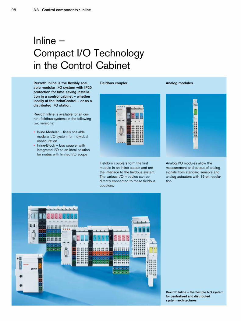
98 3.3 Control components • Inline
Rexroth Inline is the flexibly scal-able modular I/O system with IP20 protection for time-saving installa-tion in a control cabinet – whether locally at the IndraControl L or as a distributed I/O station.
Rexroth Inline is available for all cur-rent fieldbus systems in the following two versions:
• Inline-Modular – finely scalable modular I/O system for individual configuration
• Inline-Block – bus coupler with integrated I/O as an ideal solution for nodes with limited I/O scope
Fieldbus coupler
Fieldbus couplers form the first module in an Inline station and are the interface to the fieldbus system. The various I/O modules can be directly connected to these fieldbus couplers.
Analog modules
Analog I/O modules allow the measurement and output of analog signals from standard sensors and analog actuators with 16-bit resolu-tion.
Inline – Compact I/O Technology in the Control Cabinet
Rexroth Inline – the flexible I/O system for centralized and distributed system architectures.

Con
trol
com
pone
nts
• Inl
ine
Digital modules
Digital I/O modules – for connection of digital signals, from pushbuttons, limit switches or proximity switches.
Power supply/segment modules
Power supply/segment modules allow the insertion of logic voltage or to isolate segments in Inline stations.
Function modules
Function modules can be used to read relative or absolute positions or angu-lar positions.
Relay modules
Relay modules allow switching of an isolated voltage of up to 230 V AC.
DDL master modules
DDL master modules allow easy connectivity to pneumatic valves.
Block I/O modules
Rexroth Inline Block is the ideal soluti-on for low complexity applications with limited I/O requirements. The bus couplers have built-in inputs and out-puts. The compact design saves space and gives you additional options when you develop your automation solution.
Your benefit
Compact, modular and simplel Space-saving I/O technology for attachment to
standard railsl Individually combinable modulesl Well-considered assembly and installation design
99
3.3
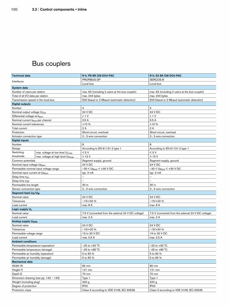
100 3.3 Control components • Inline
Bus couplers
Technical data R-IL PB BK DI8 DO4-PAC R-IL S3 BK DI8 DO4-PAC
Interfaces PROFIBUS DP SERCOS III Local bus Local bus
System data Number of users per station max. 63 (including 2 users at the bus coupler) max. 63 (including 2 users at the bus coupler)Total of all I/O data per station max. 244 bytes max. 244 bytes Transmission speed in the local bus 500 kbaud or 2 Mbaud (automatic detection) 500 kbaud or 2 Mbaud (automatic detection) Digital outputs Number 4 4 Nominal output voltage UOut 24 V DC 24 V DC Differential voltage at INom ≤ 1 V ≤ 1 V Nominal current INom per channel 0.5 A 0.5 A Nominal current tolerances +10 % +10 % Total current 2 A 2 A Protection Short-circuit, overload Short-circuit, overloadActuator connection type 2-, 3 wire connection 2-, 3 wire connection Digital inputs Number 8 8 Design According to EN 61131-2 type 1 According to EN 61131-2 type 1 Switching thresholds
max. voltage at low level ULmax < 5 V < 5 V max. voltage at high level UHmax > 15 V > 15 V
Common potentials Segment supply, ground Segment supply, groundNominal input voltage UINom 24 V DC 24 V DC Permissible nominal input voltage range –30 < UINom < +30 V DC –30 < UINom < +30 V DC Nominal input current at UINom typ. 3 mA typ. 3 mA Delay time tOn – – Delay time tOff – – Permissible line length 30 m 30 m Sensor connection type 2-, 3 wire connection 2-, 3 wire connection Segment feed US/UM Nominal value 24 V DC 24 V DC Tolerances –15/+20 % –15/+20 % Load current max. 8 A max. 8 A Logic supply UL Nominal value 7.5 V (converted from the external 24 V DC voltage) 7.5 V (converted from the external 24 V DC voltage) Load current max. 2 A max. 2 A Analog supply UANA Nominal value 24 V DC 24 V DC Tolerances –15/+20 % –15/+20 % Permissible voltage range 19 to 30 V DC 19 to 30 V DC Load current max. 0.5 A max. 0.5 A Ambient conditions Permissible temperature (operation) –25 to +55 °C –25 to +55 °C Permissible temperature (storage) –25 to +85 °C –25 to +85 °C Permissible air humidity (operation) 5 to 90 % 5 to 90 % Permissible air humidity (storage) 5 to 95 % 5 to 95 % Mechanical data Width W 80 mm 80 mm Height H 121 mm 121 mm Depth D 70 mm 70 mm Dimension drawing (see pp. 140 – 143) Type 1 Type 1Weight (including plug) 320 g 320 g Degree of protection IP20 IP20Protection class Class 3 according to VDE 0106, IEC 60536 Class 3 according to VDE 0106, IEC 60536

Con
trol
com
pone
nts
• Inl
ine
101
3.3
Technical data R-IBS IL 24 BK-T/U R-IBS IL 24 BK-DSUB R-IL DN BK R-IL CAN BK-PAC R-IL SE BK
InterfacesINTERBUS INTERBUS DeviceNet CANopen SERCOS interface (FO)
Local bus Local bus Local bus Local bus Local bus
System data Number of users
per station max. 63 max. 63 max. 63 max. 63 max. 40
Total of all I/O data
per station max. 192 bytes max. 192 bytes max. 192 bytes max. 192 bytes
max. 32 bytes inputs
and 32 bytes outputs
Transmission speed
in the local bus 500 kbaud 500 kbaud 500 kbaud 500 kbaud 500 kbaud
Segment feed US/UM
Nominal value 24 V DC 24 V DC 24 V DC 24 V DC 24 V DC
Tolerances –15/+20 % –15/+20 % –15/+20 % –15/+20 % –15/+20 %
Load current max. 8 A max. 8 A max. 8 A max. 8 A max. 8 A
Logic supply UL
Nominal value 7.5 V (converted from the
external 24 V DC voltage)
7.5 V (converted from the
external 24 V DC voltage)
7.5 V (converted from the
external 24 V DC voltage)
7.5 V (converted from the
external 24 V DC voltage)
7.5 V (converted from the
external 24 V DC voltage)
Load current max. 2 A max. 2 A max. 2 A max. 2 A max. 2 A
Analog supply UANA
Nominal value 24 V DC 24 V DC 24 V DC 24 V DC 24 V DC
Tolerances –15/+20 % –15/+20 % –15/+20 % –15/+20 % –15/+20 %
Permissible voltage range 19 to 30 V DC 19 to 30 V DC 19 to 30 V DC 19 to 30 V DC 19 to 30 V DC
Load current max. 0.5 A max. 0.5 A max. 0.5 A max. 0.5 A max. 0.5 A
Ambient conditions Permissible temperature
(operation) –25 to +55 °C –25 to +55 °C –25 to +55 °C –25 to +55 °C –25 to +55 °C
Permissible temperature
(storage) –25 to +85 °C –25 to +85 °C –25 to +85 °C –25 to +85 °C –25 to +85 °C
Permissible air humidity
(operation) 5 to 90 % 5 to 90 % 5 to 90 % 5 to 90 % 5 to 90 %
Permissible air humidity
(storage) 5 to 95 % 5 to 95 % 5 to 95 % 5 to 95 % 5 to 95 %
Mechanical data
Width W 48.8 mm 90 mm 90 mm 90 mm 90 mm
Height H 120 mm 120 mm 120 mm 120 mm 121 mm
Depth D 70 mm 70 mm 70 mm 70 mm 70 mm
Dimension drawing (see
pp. 140 – 143)Type 3 Type 2 Type 2 Type 2 Type 2
Weight (without plug) 210 g 210 g 210 g 210 g 320 g
Degree of protection IP20 IP20 IP20 IP20 IP20
Protection class Class 3 according to
VDE 0106, IEC 60536
Class 3 according to
VDE 0106, IEC 60536
Class 3 according to
VDE 0106, IEC 60536
Class 3 according to
VDE 0106, IEC 60536
Class 3 according to
VDE 0106, IEC 60536

102 3.3 Control components • Inline
Digital inputs
Technical data R-IB IL 24 DI 2 R-IB IL 24 EDI 2-DES R-IB IL 24 DI 2-NPN-PAC
Digital inputs
Number 2 2 digital inputs
+ 2 diagnostic inputs 2
Design According to EN 61131-2, type 1 According to EN 61131-2, type 1 According to EN 61131-2, type 1
Switching
thresholds
max. voltage at low level ULmax < 5 V < 6 V < 5 V
max. voltage at high level UHmax > 15 V > 13 V > 15 V
Common potentials Segment supply, ground Segment supply, ground Segment supply, ground
Nominal input voltage UINom 24 V DC 24 V DC 24 V DC
Permissible nominal input voltage range –30 < UINom < +30 V DC –30 < UINom < +30 V DC –30 < UINom < +30 V DC
Nominal input current at UINom min. 5 mA min. 3 mA min. 5 mA
Delay time tOn – – –
Delay time tOff – – –
Permissible line length 30 m 30 m 30 m
Sensor connection type 2-, 3 or 4 wire connection According to DESINA specification
or 2-, 3 wire connection 2-, 3 or 4 wire connection
Electric data
Logic voltage UL 7.5 V 7.5 V 7.5 V
Power consumption from local bus UL 35 mA 31 mA 35 mA
Nominal current consumption from US max. 0.5 A (2 x 0.25 A) max. 0.25 A max. 0.5 A
Operating mode: process data mode 2 bits 4 bits 2 bits
Transmission speed 500 kbaud 500 kbaud 500 kbaud
Error message to the higher level control system – Yes –
Ambient conditions
Permissible temperature (operation) –25 to +55 °C –25 to +55 °C –25 to +55 °C
Permissible temperature (storage) –25 to +85 °C –25 to +85 °C –25 to +85 °C
Permissible air humidity (operation) 5 to 90 % 5 to 90 % 5 to 90 %
Permissible air humidity (storage) 5 to 95 % 5 to 95 % 5 to 95 %
Mechanical data
Width W 12.2 mm 12.2 mm 12.2 mm
Height H 120 mm 120 mm 120 mm
Depth D 71.5 mm 71.5 mm 71.5 mm
Dimension drawing (see pp. 140 – 143) Type 4 Type 4 Type 4
Weight (without plug) 38 g 43 g 41 g
Degree of protection IP20 IP20 IP20
Protection class Class 3 according to VDE 0106,
IEC 60536
Class 3 according to VDE 0106,
IEC 60536
Class 3 according to VDE 0106,
IEC 60536

Con
trol
com
pone
nts
• Inl
ine
103
3.3
Technical data R-IB IL 24 DI 4 R-IB IL 24 DI 8 R-IB IL 24 DI 16
Digital inputs
Number 4 8 16
Design According to EN 61131-2, type 1 According to EN 61131-2, type 1 According to EN 61131-2, type 1
Switching
thresholds
max. voltage at low level ULmax < 5 V < 5 V < 5 V
max. voltage at high level UHmax > 15 V > 15 V > 15 V
Common potentials Segment supply, ground Segment supply, ground Segment supply, ground
Nominal input voltage UINom 24 V DC 24 V DC 24 V DC
Permissible nominal input voltage range –30 < UINom < +30 V DC –30 < UINom < +30 V DC –30 < UINom < +30 V DC
Nominal input current at UINom min. 3 mA min. 3 mA min. 3 mA
Delay time tOn – – –
Delay time tOff – – –
Permissible line length 30 m 30 m 30 m
Sensor connection type 2-, 3 or 4 wire connection 2-, 3 or 4 wire connection 2-, 3 or 4 wire connection
Electric data
Logic voltage UL 7.5 V 7.5 V 7.5 V
Power consumption from local bus UL 40 mA 50 mA 60 mA
Nominal current consumption from US max. 1.0 A max. 2.0 A max. 4.0 A
Operating mode: process data mode 4 bits 8 bits 16 bits
Transmission speed 500 kbaud 500 kbaud 500 kbaud
Error message to the higher level control system – – –
Ambient conditions
Permissible temperature (operation) –25 to +55 °C –25 to +55 °C –25 to +55 °C
Permissible temperature (storage) –25 to +85 °C –25 to +85 °C –25 to +85 °C
Permissible air humidity (operation) 5 to 90 % 5 to 90 % 5 to 90 %
Permissible air humidity (storage) 5 to 95 % 5 to 95 % 5 to 95 %
Mechanical data
Width W 12.2 mm 48.8 mm 48.8 mm
Height H 120 mm 120 mm 141 mm
Depth D 71.5 mm 71.5 mm 71.5 mm
Dimension drawing (see pp. 140 – 143) Type 5 Type 6 Type 7
Weight (without plug) 44 g 118 g 122 g
Degree of protection IP20 IP20 IP20
Protection class Class 3 according to VDE 0106,
IEC 60536
Class 3 according to VDE 0106,
IEC 60536
Class 3 according to VDE 0106,
IEC 60536

104 3.3 Control components • Inline
Digital inputs
Technical data R-IB IL 24 DI 16-NPN-PAC R-IB IL 24 DI 32/HD R-IB IL 24 DI 32/HD-NPN-PAC
Digital inputs
Number 16 32 32
Design According to EN 61131-2, type 1 According to EN 61131-2, type 1 According to EN 61131-2, type 1
Switching
thresholds
max. voltage at low level ULmax < 5 V < 5 V DC < 5 V DC
max. voltage at high level UHmax > 15 V > 15 V DC > 15 V DC
Common potentials Segment supply, ground Segment supply, ground Segment supply, ground
Nominal input voltage UINom 24 V DC 24 V DC 24 V DC
Permissible nominal input voltage range –30 < UINom < +30 V DC –30 < UINom < +30 V DC –30 < UINom < +30 V DC
Nominal input current at UINom 3 mA 2.8 mA 2.8 mA
Delay time tOn – 2 ms 2 ms
Delay time tOff – 4 ms 4 ms
Permissible line length 30 m 30 m 30 m
Sensor connection type 2-, 3 wire connection 1 wire connection 1 wire connection
Electric data
Logic voltage UL 7.5 V 7.5 V 7.5 V
Power consumption from local bus UL 60 mA 90 mA 90 mA
Nominal current consumption from US max. 4.0 A – –
Operating mode: process data mode 16 bits 32 bits 32 bits
Transmission speed 500 kbaud 500 kbaud 500 kbaud
Error message to the higher level control system – – –
Ambient conditions
Permissible temperature (operation) –25 to +55 °C –25 to +55 °C –25 to +55 °C
Permissible temperature (storage) –25 to +85 °C –25 to +85 °C –25 to +85 °C
Permissible air humidity (operation) 5 to 90 % 5 to 90 % 5 to 90 %
Permissible air humidity (storage) 5 to 95 % 5 to 95 % 5 to 95 %
Mechanical data
Width W 48.8 mm 48.8 mm 48.8 mm
Height H 141 mm 120 mm 120 mm
Depth D 71.5 mm 71.5 mm 71.5 mm
Dimension drawing (see pp. 140 – 143) Type 7 Type 6 Type 6
Weight (without plug) 122 g 125 g 125 g
Degree of protection IP20 IP20 IP20
Protection class Class 3 according to VDE 0106,
IEC 60536
Class 3 according to VDE 0106,
IEC 60536
Class 3 according to VDE 0106,
IEC 60536

Con
trol
com
pone
nts
• Inl
ine
105
3.3
Technical data R-IB IL 24 DI 8-2MBD-PAC R-IB IL 24 DI 16-2MBD-PAC
Digital inputs
Number 8 16
Design According to EN 61131-2, type 1 According to EN 61131-2, type 1
Switching
thresholds
max. voltage at low level ULmax < 5 V < 5 V
max. voltage at high level UHmax > 15 V > 15 V
Common potentials Segment supply, ground Segment supply, ground
Nominal input voltage UINom 24 V DC 24 V DC
Permissible nominal input voltage range –30 < UINom < +30 V DC –30 < UINom < +30 V DC
Nominal input current at UINom min. 3 mA min. 3 mA
Delay time tOn – –
Delay time tOff – –
Permissible line length 30 m 30 m
Sensor connection type 2-, 3 or 4 wire connection 2-, 3 wire connection
Electric data
Logic voltage UL 7.5 V 7.5 V
Power consumption from local bus UL 80 mA 80 mA
Nominal current consumption from US max. 2.0 A max. 4.0 A
Operating mode: process data mode 8 bits 16 bits
Transmission speed 2 Mbaud 2 Mbaud
Error message to the higher level control system – –
Ambient conditions
Permissible temperature (operation) –25 to +55 °C –25 to +55 °C
Permissible temperature (storage) –25 to +85 °C –25 to +85 °C
Permissible air humidity (operation) 5 to 90 % 5 to 90 %
Permissible air humidity (storage) 5 to 95 % 5 to 95 %
Mechanical data
Width W 48.8 mm 48.8 mm
Height H 120 mm 141 mm
Depth D 71.5 mm 71.5 mm
Dimension drawing (see pp. 140 – 143) Type 6 Type 7
Weight (without plug) 118 g 122 g
Degree of protection IP 20 IP20
Protection class Class 3 according to VDE 0106, IEC 60536 Class 3 according to VDE 0106, IEC 60536

106 3.3 Control components • Inline
Digital outputs
Technical data R-IB IL 24 DO 2-2A R-IB IL 24 DO 2-NPN-PAC R-IB IL 24 DO 4 R-IB IL 24 DO 8
Digital outputs
Number 2 2 4 8
Nominal output voltage UOut 24 V DC 24 V DC 24 V DC 24 V DC
Differential voltage at INom ≤ 1 V ≤ 1 V ≤ 1 V ≤ 1 V
Nominal current INom per channel 2 A 2 A 0.5 A 0.5 A
Nominal current tolerances +10 % +10 % +10 % +10 %
Total current 4 A 1 A 2 A 4 A
Protection Short-circuit/overload Short-circuit/overload Short-circuit/overload Short-circuit/overload
Signal delay upon
power on of
nominal resistive load (12 Ω/48 W) typ. 200 µs typ. 200 µs typ. 100 µs typ. 100 µs
nominal lamp load (48 W) typ. 200 µs typ. 200 µs typ. 100 µs typ. 100 µs
nominal inductive load (1.2 H, 12 Ω) typ. 250 ms typ. 250 ms typ. 100 µs typ. 100 µs
Signal delay upon
power down of
nominal resistive load (12 Ω/48 W) typ. 200 µs typ. 200 µs typ. 1 ms typ. 1 ms
nominal lamp load (48 W) typ. 200 µs typ. 200 µs typ. 1 ms typ. 1 ms
nominal inductive load (1.2 H, 12 Ω) typ. 250 ms typ. 250 ms typ. 50 ms typ. 50 ms
Actuator connection type 2-, 3 or 4 wire connection 2-, 3 or 4 wire connection 2-, 3 wire connection 2-, 3 or 4 wire connection
Electric data
Logic voltage UL 7.5 V 7.5 V 7.5 V 7.5 V
Power consumption from local bus UL max. 35 mA max. 32 mA max. 44 mA max. 60 mA
Segment supply voltage US 24 V DC (nominal value) 24 V DC (nominal value) 24 V DC (nominal value) 24 V DC (nominal value)
Nominal current consumption from US max. 4 A (2 x 2 A) max. 1 A (2 x 0.5 A) max. 2 A (2 x 0.5 A) max. 4 A (8 x 0.5 A)
Operating mode: process data mode 2 bits 2 bits 4 bits 8 bits
Transmission speed 500 kbaud 500 kbaud 500 kbaud 500 kbaud
Error message to the higher level control systemShort-circuit/overload
of an output
Short-circuit/overload
of an output
Short-circuit/overload
of an output
Short-circuit/overload
of an output
Ambient conditions
Permissible temperature (operation) –25 to +55 °C –25 to +55 °C –25 to +55 °C –25 to +55 °C
Permissible temperature (storage) –25 to +85 °C –25 to +85 °C –25 to +85 °C –25 to +85 °C
Permissible air humidity (operation) 5 to 90 % 5 to 90 % 5 to 90 % 5 to 90 %
Permissible air humidity (storage) 5 to 95 % 5 to 95 % 5 to 95 % 5 to 95 %
Mechanical data
Width W 12.2 mm 12.2 mm 12.2 mm 48.8 mm
Height H 120 mm 120 mm 121 mm 120 mm
Depth D 71.5 mm 71.5 mm 71.5 mm 71.5 mm
Dimension drawing (see pp. 140 – 143) Type 4 Type 4 Type 5 Type 6
Weight (without plug) 46 g 42 g 46 g 130 g
Degree of protection IP20 IP20 IP20 IP20
Protection class Class 3 according to
VDE 0106, IEC 60536
Class 3 according to
VDE 0106, IEC 60536
Class 3 according to
VDE 0106, IEC 60536
Class 3 according to
VDE 0106, IEC 60536

Con
trol
com
pone
nts
• Inl
ine
107
3.3
Technical data R-IB IL 24 DO 8-2A R-IB IL 24 DO 8-NPN-PAC R-IB IL 24 DO 16
Digital outputs
Number 8 8 16
Nominal output voltage UOut 24 V DC 24 V DC 24 V DC
Differential voltage at INom ≤ 1 V ≤ 1 V ≤ 1 V
Nominal current INom per channel 2 A 0.5 A 0.5 A
Nominal current tolerances +10 % +10 % +10 %
Total current 8 A (at 50 % synchronism) 4 A 8 A
Protection Short-circuit/overload Short-circuit/overload Short-circuit/overload
Signal delay upon
power on of
nominal resistive load (12 Ω/48 W) typ. 50 µs typ. 100 µs typ. 500 µs
nominal lamp load (48 W) typ. 75 ms typ. 100 ms typ. 100 ms
nominal inductive load (1.2 H, 12 Ω) typ. 50 ms typ. 100 ms typ. 100 ms
Signal delay upon
power down of
nominal resistive load (12 Ω/48 W) typ. 500 µs typ. 1 ms typ. 1 ms
nominal lamp load (48 W) typ. 500 µs typ. 1 ms typ. 1 ms
nominal inductive load (1.2 H, 12 Ω) typ. 150 ms typ. 50 ms typ. 50 ms
Actuator connection type 2-, 3 or 4 wire connection 2-, 3 or 4 wire connection 2-, 3 wire connection
Electric data
Logic voltage 7.5 V 7.5 V 7.5 V
Power consumption from local bus UL max. 60 mA max. 60 mA max. 90 mA
Segment supply voltage US 24 V DC (nominal value) 24 V DC (nominal value) 24 V DC (nominal value)
Nominal current consumption from US max. 8 A max. 4 A (8 x 0.5 A) max. 8 A (16 x 0.5 A)
Operating mode: process data mode 8 bits 4 bits 16 bits
Transmission speed 500 kbaud 500 kbaud 500 kbaud
Error message to the higher level control system – Short-circuit/overload
of an output
Short-circuit/overload
of an output
Ambient conditions
Permissible temperature (operation) –25 to +55 °C –25 to +55 °C –25 to +55 °C
Permissible temperature (storage) –25 to +85 °C –25 to +85 °C –25 to +85 °C
Permissible air humidity (operation) 5 to 90 % 5 to 90 % 5 to 90 %
Permissible air humidity (storage) 5 to 95 % 5 to 95 % 5 to 95 %
Mechanical data
Width W 48.8 mm 48.8 mm 48.8 mm
Height H 120 mm 120 mm 141 mm
Depth D 71.5 mm 71.5 mm 71.5 mm
Dimension drawing (see pp. 140 – 143) Type 6 Type 6 Type 7
Weight (without plug) 130 g 130 g 130 g
Degree of protection IP20 IP20 IP20
Protection class Class 3 according to VDE 0106,
IEC 60536
Class 3 according to VDE 0106,
IEC 60536
Class 3 according to VDE 0106,
IEC 60536

108 3.3 Control components • Inline
Technical data R-IB IL 24 DO 32/HD R-IB IL 24 DO 32/HD-NPN-PAC R-IB IL 24 DO 2-2A-2MBD-PAC
Digital outputs
Number 32 32 2
Nominal output voltage UOut 24 V DC 24 V DC 24 V DC
Differential voltage at INom ≤ 1 V ≤ 1 V ≤ 1 V
Nominal current INom per channel 0.5 A 0.5 A 2 A
Nominal current tolerances +10 % +10 % +10 %
Total current 8 A 8 A 4 A
Protection Short-circuit/overload Short-circuit/overload Short-circuit/overload
Signal delay upon
power on of
nominal resistive load (12 Ω/48 W) typ. 500 µs typ. 500 µs typ. 200 µs
nominal lamp load (48 W) typ. 100 µs typ. 100 µs typ. 200 µs
nominal inductive load (1.2 H, 12 Ω) typ. 100 µs typ. 100 µs typ. 250 µs
Signal delay upon
power down of
nominal resistive load (12 Ω/48 W) typ. 1 µs typ. 1 µs typ. 200 µs
nominal lamp load (48 W) typ. 1 µs typ. 1 µs typ. 200 µs
nominal inductive load (1.2 H, 12 Ω) typ. 50 µs typ. 50 µs typ. 250 µs
Actuator connection type 1 wire connection 1 wire connection 2-, 3 or 4 wire connection
Electric data
Logic voltage 7.5 V 7.5 V 7.5 V
Power consumption from local bus UL max. 140 mA max. 140 mA max. 60 mA
Segment supply voltage US 24 V DC (nominal value) 24 V DC (nominal value) 24 V DC (nominal value)
Nominal current consumption from US max. 8 A (16 x 0.5 A
or 32 x 0.25 A)
max. 8 A (16 x 0.5 A
or 32 x 0.25 A) max. 4 A (2 x 2 A)
Operating mode: process data mode 32 bits 32 bits 2 bits
Transmission speed 500 kbaud 500 kbaud 2 Mbaud
Error message to the higher level control systemShort-circuit/overload
of an output
Short-circuit/overload
of an output
Short-circuit/overload
of an output
Ambient conditions
Permissible temperature (operation) –25 to +55 °C –25 to +55 °C –25 to +55 °C
Permissible temperature (storage) –25 to +85 °C –25 to +85 °C –25 to +85 °C
Permissible air humidity (operation) 5 to 90 % 5 to 90 % 5 to 90 %
Permissible air humidity (storage) 5 to 95 % 5 to 95 % 5 to 95 %
Mechanical data
Width W 48.8 mm 48.8 mm 12.2 mm
Height H 120 mm 120 mm 120 mm
Depth D 71.5 mm 71.5 mm 71.5 mm
Dimension drawing (see pp. 140 – 143) Type 6 Type 6 Type 4
Weight (without plug) 135 g 135 g 46 g
Degree of protection IP20 IP20 IP20
Protection class Class 3 according to VDE 0106,
IEC 60536
Class 3 according to VDE 0106,
IEC 60536
Class 3 according to VDE 0106,
IEC 60536
Digital outputs

Con
trol
com
pone
nts
• Inl
ine
109
3.3
Technical data R-IB IL 24 DO 4-2MBD-PAC R-IB IL 24 DO 8-2MBD-PAC R-IB IL 24 DO 16-2MBD-PAC
Digital outputs
Number 4 8 16
Nominal output voltage UOut 24 V DC 24 V DC 24 V DC
Differential voltage at INom ≤ 1 V ≤ 1 V ≤ 1 V
Nominal current INom per channel 2 A 0.5 A 1 A
Nominal current tolerances +10 % +10 % +10 %
Total current 4 A 4 A 8 A
Protection Short-circuit/overload Short-circuit/overload Short-circuit/overload
Signal delay upon
power on of
nominal resistive load (12 Ω/48 W) typ. 200 µs typ. 100 µs typ. 500 µs
nominal lamp load (48 W) typ. 200 µs typ. 100 µs typ. 100 µs
nominal inductive load (1.2 H, 12 Ω) typ. 250 µs typ. 100 µs typ. 100 µs
Signal delay upon
power down of
nominal resistive load (12 Ω/48 W) typ. 200 µs typ. 1 µs typ. 1 µs
nominal lamp load (48 W) typ. 200 µs typ. 1 µs typ. 1 µs
nominal inductive load (1.2 H, 12 Ω) typ. 250 µs typ. 50 µs typ. 50 µs
Actuator connection type 2-, 3 or 4 wire connection 2-, 3 or 4 wire connection 2-, 3 wire connection
Electric data
Logic voltage UL 7.5 V 7.5 V 7.5 V
Power consumption from local bus UL max. 65 mA max. 85 mA max. 105 mA
Segment supply voltage US 24 V DC (nominal value) 24 V DC (nominal value) 24 V DC (nominal value)
Nominal current consumption from US max. 2 A (4 x 0.5 A) max. 4 A (8 x 0.5 A) max. 8 A (16 x 0.5 A)
Operating mode: process data mode 4 bits 8 bits 16 bits
Transmission speed 2 Mbaud 2 Mbaud 2 Mbaud
Error message to the higher level control systemShort-circuit/overload
of an output
Short-circuit/overload
of an output
Short-circuit/overload
of an output
Ambient conditions
Permissible temperature (operation) –25 to +55 °C –25 to +55 °C –25 to +55 °C
Permissible temperature (storage) –25 to +85 °C –25 to +85 °C –25 to +85 °C
Permissible air humidity (operation) 5 to 90 % 5 to 90 % 5 to 90 %
Permissible air humidity (storage) 5 to 95 % 5 to 95 % 5 to 95 %
Mechanical data
Width W 12.2 mm 48.8 mm 48.8 mm
Height H 141 mm 120 mm 141 mm
Depth D 71.5 mm 71.5 mm 71.5 mm
Dimension drawing (see pp. 140 – 143) Type 5 Type 6 Type 7
Weight (without plug) 44 g 130 g 130 g
Degree of protection IP20 IP20 IP20
Protection class Class 3 according to VDE 0106,
IEC 60536
Class 3 according to VDE 0106,
IEC 60536
Class 3 according to VDE 0106,
IEC 60536

110 3.3 Control components • Inline
Analog inputs
Technical data R-IB IL 24 AI 2/SF R-IB IL 24 AI 2/SF-230-PAC
Analog inputs
Number 2 anlog single-ended inputs 2 anlog single-ended inputs
Digital filtering (averaging) Across 16 measurement values (can be switched off) Across 16 measurement values (can be switched off)
Conversion time of A/D converter typ. 120 µs typ. 120 µs
Voltage inputs
Measuring ranges 0 to 10 V, ±10 V 0 to 10 V, ±10 V
Input resistance > 220 kΩ > 220 kΩ
Limit frequency (–3 dB) of input filters 40 Hz 230 Hz
Process data update of either channel < 1.5 ms < 1.5 ms
Current inputs
Input resistance 50 Ω 50 Ω
Measuring ranges 0 to 20 mA, ±20 mA, 4 to 20 mA 0 to 20 mA, ±20 mA, 4 to 20 mA
Limit frequency (–3 dB) of input filters 40 Hz 230 Hz
Process data update of either channel < 1.5 ms < 1.5 ms
Max. permissible current in each input ±100 mA ±100 mA
Resolution 16 bits 16 bits
Sensor connection type 2-, 3 wire connection 2-, 3 wire connection
Electric data
Logic voltage UL 7.5 V 7.5 V
Power consumption from local bus UL typ. 45 mA typ. 45 mA
Peripheral supply voltage UANA 24 V DC 24 V DC
Power consumption at UANA typ. 12 mA typ. 12 mA
Operating mode: process data mode 32 bits 32 bits
Transmission speed 500 kbaud 500 kbaud
Error message to the higher level control system Failure of supply voltage UANA,
peripheral/user error
Failure of supply voltage UANA,
peripheral/user error
Ambient conditions
Permissible temperature (operation) –25 to +55 °C –25 to +55 °C
Permissible temperature (storage) –25 to +85 °C –25 to +85 °C
Permissible air humidity (operation) 5 to 90 %, no dewing 5 to 90 %, no dewing
Permissible air humidity (storage) 5 to 95 %, no dewing 5 to 95 %, no dewing
Mechanical data
Width W 12.2 mm 12.2 mm
Height H 135 mm 135 mm
Depth D 71.5 mm 71.5 mm
Dimension drawing (see pp. 140 – 143) Type 8 Type 8
Weight (without plug) 47 g 47 g
Degree of protection IP20 IP20
Protection class Class 3 according to VDE 0106, IEC 60536 Class 3 according to VDE 0106, IEC 60536

Con
trol
com
pone
nts
• Inl
ine
111
3.3
Technical data R-IB IL AI 8/IS-PAC
Analog inputs
Number 8 analog single-ended inputs
Digital filtering (averaging) None or across 4, 16 or 32 measurement values
Conversion time of A/D converter max. 10 µs
Current inputs
Input resistance 25 Ω
Measuring ranges 0 to 20 mA, 4 to 20 mA, ±20 mA, 0 to 40 mA, ±40 mA
Limit frequency (–3 dB) of input filters 3.5 kHz
Process data update of either channel Synchronous with the bus
Max. permissible current in each input ±100 mA
Resolution 16 bits
Sensor connection type 2-, 3 wire connection
Electric data
Logic voltage UL 7.5 V
Power consumption from local bus UL typ. 52 mA, max. 65 mA
Peripheral supply voltage UANA 24 V DC
Power consumption at UANA typ. 31 mA, max. 40 mA
Operating mode: process data mode 2 words
Transmission speed 500 kbaud
Error message to the higher level control system Failure of supply voltage UANA, peripheral/user error
Ambient conditions
Permissible temperature (operation) –25 to +55 °C
Permissible temperature (storage) –25 to +85 °C
Permissible air humidity (operation) 5 to 90 %, no dewing
Permissible air humidity (storage) 5 to 95 %, no dewing
Mechanical data
Width W 48.8 mm
Height H 135 mm
Depth D 71.5 mm
Dimension drawing (see pp. 140 – 143) Type 10
Weight (without plug) 125 g
Degree of protection IP20
Protection class Class 3 according to VDE 0106, IEC 60536

112 3.3 Control components • Inline
Analog inputs
Technical data R-IB IL 24 AI 8/SF-PAC
Analog inuts
Number 8 analog single-ended inputs
Digital filtering (averaging) None or across 4, 16 or 32 measurement values
Conversion time of A/D converter max. 10 µs
Voltage inputs
Measuring ranges 0 to 10 V, ±10 V, 0 to 5 V, ±5 V, 0 to 25 V, ±25 V, 0 to 50 V
Input resistance min. 240 kΩ
Limit frequency (–3 dB) of input filters 3.5 kHz
Process data update of either channel < 1.5 ms
Current inputs
Input resistance 25 Ω
Measuring ranges 0 to 20 mA, 4 to 20 mA, ±20 mA, 0 to 40 mA, ±40 mA
Limit frequency (–3 dB) of input filters 3.5 kHz
Process data update of either channel < 1.5 ms
Max. permissible current in each input ±100 mA
Resolution 16 bits
Sensor connection type 2 wire connection
Electric data
Logic voltage UL 7.5 V
Power consumption from local bus UL typ. 48 mA, max. 55 mA
Peripheral supply voltage UANA 24 V DC
Power consumption at UANA typ. 30 mA, max. 35 mA
Operating mode: process data mode 32 bits
Transmission speed 500 kbaud
Error message to the higher level control system Failure of supply voltage UANA, peripheral/user error
Ambient conditions
Permissible temperature (operation) –25 to +55 °C
Permissible temperature (storage) –25 to +85 °C
Permissible air humidity (operation) 5 to 90 %, no dewing
Permissible air humidity (storage) 5 to 95 %, no dewing
Mechanical data
Width W 48.8 mm
Height H 120 mm
Depth D 71.5 mm
Dimension drawing (see pp. 140 – 143) Type 10
Weight (without plug) 125 g
Degree of protection IP20
Protection class Class 3 according to VDE 0106, IEC 60536

Con
trol
com
pone
nts
• Inl
ine
113
3.3
Technical data R-IB IL SGI 2/F-PAC
Analog inputs
Number 2 input channel for strain gauges (4 voltage inputs)
Bridge voltage U0 3.3 V (±0.5 V) or 5 V (±0.5 V)
Measured value representation 15 bits + sign
Process data update Synchronous with the bus
Bus cycle time ≥ 1 ms
Limit frequency of differential bridge input typ. 1.6 kHz
Strain gauge connection type Six- and four-wire principle
Outputs
Number 2 voltage outputs (UV = 3.3 V, UV = 5 V)
Total impedance of Inline module > 60 Ω
Electric data
Logic voltage UL 7.5 V
Power consumption from local bus UL typ. 75 mA
Peripheral supply voltage UANA 24 V DC
Power consumption at UANA typ. 30 mA, max. 35 mA
Without strain gauge typ. 8 mA
With maximum load 60 Ω 32 mA (typ. bei UV = 5 V)
Operating mode: process data mode 48 bits
Transmission speed 500 kbaud
Error message to the higher level control system Yes
Ambient conditions
Permissible temperature (operation) –25 to +55 °C
Permissible temperature (storage) –25 to +85 °C
Permissible air humidity (operation) 5 to 90 %, no dewing
Permissible air humidity (storage) 5 to 95 %, no dewing
Mechanical data
Width W 48.8 mm
Height H 135 mm
Depth D 71.5 mm
Dimension drawing (see pp. 140 – 143) Type 10
Weight (without plug) 125 g
Degree of protection IP20
Protection class Class 3 according to VDE 0106, IEC 60536

114 3.3 Control components • Inline
Technical data R-IB IL 24 AI 8/SF-2MBD-PAC
Analog inputs
Number 8 analog single-ended inputs
Digital filtering (averaging) None or across 4, 16 or 32 measurement values
Conversion time of A/D converter max. 10 µs
Voltage inputs
Measuring ranges 0 to 10 V, ±10 V, 0 to 5 V, ±5 V, 0 to 25 V, ±25 V, 0 to 50 V
Input resistance min. 240 kΩ
Limit frequency (–3 dB) of input filters 3.5 kHz
Process data update of either channel < 1.5 ms
Current inputs
Input resistance 25 Ω
Measuring ranges 0 to 20 mA, 4 to 20 mA, ±20 mA, 0 to 40 mA, ±40 mA
Limit frequency (–3 dB) of input filters 3.5 kHz
Process data update of either channel < 1.5 ms
Max. permissible current in each input ±100 mA
Resolution 16 bits
Sensor connection type 2 wire connection
Electric data
Logic voltage UL 7.5 V
Power consumption from local bus UL typ. 68 mA, max. 85 mA
Peripheral supply voltage UANA 24 V DC
Power consumption at UANA typ. 24 mA, max. 38 mA
Operating mode: process data mode 32 bits
Transmission speed 2 Mbaud
Error message to the higher level control system Failure of supply voltage UANA, peripheral/user error
Ambient conditions
Permissible temperature (operation) –25 to +55 °C
Permissible temperature (storage) –25 to +85 °C
Permissible air humidity (operation) 5 to 90 %, no dewing
Permissible air humidity (storage) 5 to 95 %, no dewing
Mechanical data
Width W 48.8 mm
Height H 135 mm
Depth D 71.5 mm
Dimension drawing (see pp. 140 – 143) Type 10
Weight (without plug) 125 g
Degree of protection IP20
Protection class Class 3 according to VDE 0106, IEC 60536
Analog inputs

Con
trol
com
pone
nts
• Inl
ine
115
3.3
Technical data R-IB IL SGI 2/F-2MBD-PAC
Analog outputs
Number 2 voltage outputs (UV = 3.3 V, UV = 5 V)
Total impedance of Inline module > 60 Ω
Analog inputs
Number 2 input channel for strain gauges (four voltage inputs)
Bridge voltage U0 3.3 V (±0.5 V) or 5 V (±0.5 V)
Measured value representation 15 bits + sign
Process data update Synchronous with the bus
Bus cycle time ≥ 1 ms
Limit frequency of differential bridge input typ. 1.6 kHz
Strain gauge connection type Six- and four-wire principle
Electric data
Logic voltage UL 7.5 V
Power consumption from local bus UL typ. 100 mA
Peripheral supply voltage UANA 24 V DC
Power consumption at UANA
Without strain gauge typ. 8 mA
With maximum load 60 Ω typ. 32 mA (at UV = 5 V)
Operating mode: process data mode 48 bits
Transmission speed 2 Mbaud
Error message to the higher level control system Yes
Ambient conditions
Permissible temperature (operation) –25 to +55 °C
Permissible temperature (storage) –25 to +85 °C
Permissible air humidity (operation) 5 to 90 %, no dewing
Permissible air humidity (storage) 5 to 95 %, no dewing
Mechanical data
Width W 48.8 mm
Height H 135 mm
Depth D 71.5 mm
Dimension drawing (see pp. 140 – 143) Type 10
Weight (without plug) 125 g
Degree of protection IP20
Protection class Class 3 according to VDE 0106, IEC 60536

116 3.3 Control components • Inline
Technical data R-IB IL TEMP 2 RTD R-IB IL TEMP 4/8 RTD-2MBD-PAC
Analog inputs
Number 2 inputs for resistive temperature sensors 8 inputs for resistive temperature sensors
Usable sensor types Pt, Ni, Cu, KTY Pt, Ni, Cu, KTY, linear resistors
Characteristic current According to DIN,
according to SAMA
According to DIN EN 60751: 07/1996,
according to SAMA RC 21-4-1966
Conversion time of A/D converter typ. 120 µs typ. 5 µs, max. 10 µs
Voltage input range – –15 bis +85 mV
Process data update Depending on connection method Depending on connection method
Both channels acc. to two-wire principle 20 ms –
One channel acc. to two-wire principle,
one channel acc. to four-wire principle 20 ms –
Both channels acc. to three-wire principle 32 ms –
Sensor connection type 2-, 3 or 4 wire connection 2-, 3 wire connection
Electric data
Logic voltage UL 7.5 V 7.5 V
Power consumption from local bus UL typ. 43 mA typ. 100 mA
Peripheral supply voltage UANA 24 V DC 24 V DC
Power consumption at UANA typ. 11 mA typ. 41 mA
Operating mode: process data mode 32 bits 80 bits
Transmission speed 500 kbaud 2 Mbaud
Error message to the higher level control system Failure of supply voltage UANA,
peripheral/user error
Failure of supply voltage UANA,
peripheral/user error
Ambient conditions
Permissible temperature (operation) –25 to +55 °C –25 to +55 °C
Permissible temperature (storage) –25 to +85 °C –25 to +85 °C
Permissible air humidity (operation) 5 to 90 %, no dewing 5 to 90 %, no dewing
Permissible air humidity (storage) 5 to 95 %, no dewing 5 to 95 %, no dewing
Mechanical data
Width W 12.2 mm 48.8 mm
Height H 135 mm 120 mm
Depth D 71.5 mm 71.5 mm
Dimension drawing (see pp. 140 – 143) Type 8 Type 10
Weight (without plug) 46 g 125 g
Degree of protection IP20 IP20
Protection class Class 3 according to VDE 0106, IEC 60536 Class 3 according to VDE 0106, IEC 60536
Temperature modules

Con
trol
com
pone
nts
• Inl
ine
117
3.3
Technical data R-IB IL TEMP 2 UTH-PAC
Analog inputs
Number 2 inputs for thermcouples or linear voltages
Usable sensor types B, C, E, J, K, L, N, R, S, T, U, W, HK
Characteristic current DIN EN 60584-1: 1995 (B, E, J, K, N, R, S, T) DIN 43710 (U, L)
Voltage input range –15 to +85 mV
Conversion time of A/D converter typ. 120 µs
Process data update max. 30 ms for either channel
Limit frequency of analog filter 48 Hz
Sensor connection type 2 wire connection
Electric data
Logic voltage UL 7.5 V
Power consumption from local bus UL typ. 43 mA
Peripheral supply voltage UANA 24 V DC
Power consumption at UANA typ. 11 mA
Operating mode: process data mode 32 bits
Transmission speed 500 kbaud
Error message to the higher level control system Failure of supply voltage UANA, peripheral/user error
Ambient conditions
Permissible temperature (operation) –25 to +55 °C
Permissible temperature (storage) –25 to +85 °C
Permissible air humidity (operation) 5 to 90 %, no dewing
Permissible air humidity (storage) 5 to 95 %, no dewing
Mechanical data
Width W 12.2 mm
Height H 135 mm
Depth D 71.5 mm
Dimension drawing (see pp. 140 – 143) Type 8
Weight (without plug) 46 g
Degree of protection IP20
Protection class Class 3 according to VDE 0106, IEC 60536

118 3.3 Control components • Inline
Technical data R-IB IL TEMP 4/8 RTD-PAC
Analog inputs
Number 8 inputs for resistive temperature sensors
Usable sensor types Pt, Ni, Cu, KTY, linear resistors
Characteristic current According to DIN EN 60751: 07/1996; according to SAMA RC 21-4-1966
Voltage input range –15 to +85 mV
Conversion time of A/D converter typ. 5 µs, max. 10 µs
Process data update Depending on connection method
Sensor connection type 2-, 3 wire connection
Electric data
Logic voltage UL 7.5 V
Power consumption from local bus UL typ. 75 mA
Peripheral supply voltage UANA 24 V DC
Power consumption at UANA typ. 28 mA
Operating mode: process data mode 80 bits
Transmission speed 500 kbaud
Error message to the higher level control system Failure of supply voltage UANA, peripheral/user error
Ambient conditions
Permissible temperature (operation) –25 to +55 °C
Permissible temperature (storage) –25 to +85 °C
Permissible air humidity (operation) 5 to 90 %, no dewing
Permissible air humidity (storage) 5 to 95 %, no dewing
Mechanical data
Width W 48.8 mm
Height H 135 mm
Depth D 71.5 mm
Dimension drawing (see pp. 140 – 143) Type 10
Weight (without plug) 125 g
Degree of protection IP20
Protection class Class 3 according to VDE 0106, IEC 60536
Temperature modules

Con
trol
com
pone
nts
• Inl
ine
119
3.3
Technical data R-IB IL AO 2/U/BP
Analog outputs
Number 2 single-ended outputs
Voltage ranges –10 to +10 V/0 to +10 V
Basic error limit ±0.02 %
Output load min. 2 kΩ
Resolution 16 bits
Process data update including conversation time of D/A converter < 1 ms
Actuator connection type 2 wire connection
Electric data
Logic voltage UL 7.5 V
Power consumption from local bus UL typ. 33 mA, max. 40 mA
Peripheral supply voltage UANA 24 V DC
Power consumption at UANA typ. 25 mA, max. 35 mA
Operating mode: process data mode 32 bits
Transmission speed 500 kbaud
Error message to the higher level control system Failure or logic voltage UL not reached
Ambient conditions
Permissible temperature (operation) –25 to +55 °C
Permissible temperature (storage) –25 to +85 °C
Permissible air humidity (operation) 5 to 90 %, no dewing
Permissible air humidity (storage) 5 to 95 %, no dewing
Mechanical data
Width W 12.2 mm
Height H 135 mm
Depth D 71.5 mm
Dimension drawing (see pp. 140 – 143) Type 8
Weight (without plug) 48 g
Degree of protection IP20
Protection class Class 3 according to VDE 0106, IEC 60536
Analog outputs

120 3.3 Control components • Inline
Technical data R-IB IL AO 1/SF
Analog outputs
Number 1, automatically configured in relation to the terminal point used
Current ranges 0 to 20 mA, 4 to 20 mA
Voltage ranges 0 to 10 V
Output load
Voltage ouput 2 kΩ
Current output 0 to 500 Ω
Resolution 16 bits
Process data update including conversion time of D/A converter < 1 ms
Actuator connection type 2 wire connection
Electric data
Logic voltage UL 7.5 V
Power consumption from local bus UL typ. 30 mA, max. 40 mA
Peripheral supply voltage UANA 24 V DC
Power consumption at UANA typ. 50 mA, max. 65 mA
Operating mode: process data mode 32 bits
Transmission speed 500 kbaud
Error message to the higher level control system Failure or logic voltage UL not reached
Ambient conditions
Permissible temperature (operation) –25 to +55 °C
Permissible temperature (storage) –25 to +85 °C
Permissible air humidity (operation) 5 to 90 %, no dewing
Permissible air humidity (storage) 5 to 95 %, no dewing
Mechanical data
Width W 24.4 mm
Height H 135 mm
Depth D 71.5 mm
Dimension drawing (see pp. 140 – 143) Type 9
Weight (without plug) 48 g
Degree of protection IP20
Protection class Class 3 according to VDE 0106, IEC 60536
Analog outputs

Con
trol
com
pone
nts
• Inl
ine
121
3.3
Technical data R-IB IL AO 2/SF-PAC
Analog outputs
Number 2, automatically configured in relation to the terminal point used
Current ranges 0 to 20 mA, 4 to 20 mA
Voltage ranges 0 to 10 V
Basic error limit within current range ±0.003 %
Output load
Voltage ouput min. 2 kΩ
Current output 0 to 500 Ω
Resolution 16 bits
Process data update including conversion time of D/A converter < 1 ms
Actuator connection type 2 wire connection
Electric data
Logic voltage UL 7.5 V
Power consumption from local bus UL typ. 36 mA, max. 45 mA
Peripheral supply voltage UANA 24 V DC
Power consumption at UANA typ. 75 mA, max. 95 mA
Operating mode: process data mode 32 bits
Transmission speed 500 kbaud
Error message to the higher level control system Failure of supply voltage UANA
Ambient conditions
Permissible temperature (operation) –25 to +55 °C
Permissible temperature (storage) –25 to +85 °C
Permissible air humidity (operation) 5 to 90 %, no dewing
Permissible air humidity (storage) 5 to 95 %, no dewing
Mechanical data
Width W 48.8 mm
Height H 135 mm
Depth D 71.5 mm
Dimension drawing (see pp. 140 – 143) Type 10
Weight (without plug) 125 g
Degree of protection IP20
Protection class Class 3 according to VDE 0106, IEC 60536

122 3.3 Control components • Inline
Technical data R-IB IL AO 2/SF-2MBD-PAC
Analog outputs
Number 2, automatically configured in relation to the terminal point used
Current ranges 0 to 20 mA, 4 mA to 20 mA
Voltage ranges 0 to 10 V
Basic error limit within current range ±0.003 %
Output load
Voltage ouput min. 2 kΩ
Current output 0 to 500 Ω
Resolution 16 bits
Process data update including conversion time of D/A converter < 1 ms
Actuator connection type 2 wire connection
Electric data
Logic voltage UL 7.5 V
Power consumption from local bus UL typ. 60 mA, max. 75 mA
Peripheral supply voltage UANA 24 V DC
Power consumption at UANA typ. 75 mA, max. 95 mA
Operating mode: process data mode 32 bits
Transmission speed 2 Mbaud
Error message to the higher level control system Failure of supply voltage UANA
Ambient conditions
Permissible temperature (operation) –25 to +55 °C
Permissible temperature (storage) –25 to +85 °C
Permissible air humidity (operation) 5 to 90 %, no dewing
Permissible air humidity (storage) 5 to 95 %, no dewing
Mechanical data
Width W 48.8 mm
Height H 135 mm
Depth D 71.5 mm
Dimension drawing (see pp. 140 – 143) Type 10
Weight (without plug) 125 g
Degree of protection IP20
Protection class Class 3 according to VDE 0106, IEC 60536
Analog outputs

Con
trol
com
pone
nts
• Inl
ine
123
3.3
Technical data R-IB IL AO 4/8/U/BP-2MBD-PAC
Analog outputs
Number 8
Voltage ranges 0 to 10 V, 0 to 5 V, ±10 V, ±5 V
Basic error limit typ. ±0,1 % of output range and value
Output load typ. 30 kΩ, min. 2 kΩ
Resolution 16 bits
Process data update including conversation time of D/A converter 2 ms
Actuator connection type 2 wire connection with shield connection
Electric data
Logic voltage UL 7.5 V
Power consumption from local bus UL typ. 80 mA
Peripheral supply voltage UANA 24 V DC
Power consumption at UANA typ. 72 mA
Operating mode: process data mode 32 bits
Transmission speed 500 kbaud
Error message to the higher level control system Failure or logic voltage UL not reached, failure of internal peripheral voltage supply
Ambient conditions
Permissible temperature (operation) –25 to +55 °C
Permissible temperature (storage) –25 to +85 °C
Permissible air humidity (operation) 5 to 90 %, no dewing
Permissible air humidity (storage) 5 to 95 %, no dewing
Mechanical data
Width W 12.2 mm
Height H 135 mm
Depth D 71.5 mm
Dimension drawing (see pp. 140 – 143) Type 10
Weight (without plug) 48 g
Degree of protection IP20
Protection class Class 3 according to VDE 0106, IEC 60536

124 3.3 Control components • Inline
Power supply/segment modules
Technical data R-IB IL PWR IN R-IB IL 24 PWR IN/2F-D-2MBD-PAC
24-V peripheral supply (main circuit UM)
Rated value 24 V DC 24 V DC
Permissible range 19.2 to 30 V 19.2 to 30 V
Permissible current max. 8 A max. 8 A
Electric data
Operating mode: process data mode – 2 bits
Transmission speed 500 kbaud 2 Mbaud
Error message to the higher level control system – Yes
Ambient conditions
Permissible temperature (operation) –25 to +55 °C –25 to +55 °C
Permissible temperature (storage) –25 to +85 °C –25 to +85 °C
Permissible air humidity (operation) 5 to 90 % 5 to 90 %
Permissible air humidity (storage) 5 to 95 % 5 to 95 %
Mechanical data
Width W 12.2 mm 12.2 mm
Height H 120 mm 120 mm
Depth D 71.5 mm 71.5 mm
Dimension drawing (see pp. 140 – 143) Type 4 Type 4
Weight (without plug) 44 g 44 g
Degree of protection IP20 IP20
Protection class Class 3 according to VDE 0106, IEC 60536 Class 3 according to VDE 0106, IEC 60536
Technical data R-IB IL 24 SEG/F R-IB IL 24 SEG/F-D-2MBD-PAC
24-V peripheral supply (main circuit UM)
Voltage supply is in the bus terminal or in the supply terminal. No connections for the supply voltage are required at the segment terminal.
The appropriate terminal points are available for testing purposes.
Permissible total current in the potential terminals of the main and segment circuits
Nominal terminal current 6.0 A 6.0 A
Max. permissible value 8.0 A 8.0 A
Electric data
Operating mode: process data mode – –
Transmission speed 500 kbaud 2 Mbaud
Error message to the higher level control system – Yes
Ambient condition
Permissible temperature (operation) –25 to +55 °C –25 to +55 °C
Permissible temperature (storage) –25 to +85 °C –25 to +85 °C
Permissible air humidity (operation) 5 to 90 % 5 to 90 %
Permissible air humidity (storage) 5 to 95 % 5 to 95 %
Mechanical data
Width W 12.2 mm 12.2 mm
Height H 120 mm 120 mm
Depth D 71.5 mm 71.5 mm
Dimension drawing (see pp. 140 – 143) Type 4 Type 4
Weight (without plug) 44 g 44 g
Degree of protection IP20 IP20
Protection class Class 3 according to VDE 0106, IEC 60536 Class 3 according to VDE 0106, IEC 60536

Con
trol
com
pone
nts
• Inl
ine
125
3.3
Technical data R-IB IL PWR IN/R-PAC
24-V power supply for generation of UL and UANA
Rated value 24 V DC
Permissible range 19.2 to 30 V DC
Power consumption at nominal voltage
24-V module supply 1.25 A DC
Logic supply Rated value 7.5 V DC
max. output current 2 A DC
Analog supplyRated value 24 V DC
max. output current 0.5 A DC
24-V peripheral supply (main circuit UM)
Rated value 24 V DC
Permissible range 19.2 to 30 V
Permissible current max. 8 A
Electric data
Operating mode: process data mode –
Transmission speed 500 kbaud
Error message to the higher level control system –
Ambient conditions
Permissible temperature (operation) –25 to +55 °C
Permissible temperature (storage) –25 to +85 °C
Permissible air humidity (operation) 5 to 90 %
Permissible air humidity (storage) 5 to 95 %
Mechanical data
Width W 48.8 mm
Height H 120 mm
Depth D 71.5 mm
Dimension drawing (see pp. 140 – 143) Type 6
Weight (without plug) 132 g
Degree of protection IP20
Protection class Class 3 according to VDE 0106, IEC 60536

126 3.3 Control components • Inline
Function modules
Technical data R-IB IL CNT – counter module
Digital inputs
Number 4
1 counter input for 24-V signals
1 counter input for 5-V signals
1 control input for 24-V signals
1 control input for 5-V signals
Nominal input voltage UIn 24 V DC
Nominal input current UIn 5 mA
Delay time < 5 µs
24-V sensor connection type 2-, 3 wire connection
5-V sensor connection type 2 wire connection
Switching output
Number 1
Nominal output voltage UOut 24 V DC
Nominal current INom max. 0.5 A
Electric data
Logic voltage UL 7.5 V
Power consumption from local bus UL typ. 40 mA, max. 50 mA
Nominal voltage US 24 V DC
Nominal current consumption at US max. 1 A
Operating mode: process data mode 32 bits
Transmission speed 500 kbaud
Error message to the higher level control system Short-circuit/overload of sensor supply
Frequency measurement f ≤ 100 kHz
Event counting f ≤ 100 kHz
Time measurement
0.25 ms ≤ t ≤ 131 ms (Resolution 2 µs, without relation conditons)
1 ms ≤ t ≤131 ms (Resolution 2 µs, with relation conditions)
2 ms ≤ t ≤ 131 s (Resolution 2 ms)
10 ms ≤ t ≤ 655 s (Resolution 10 ms)
Pulse generator 1 kHz ≤ f ≤ 10 kHz
Ambient conditions
Permissible temperature (operation) –25 to +55 °C
Permissible temperature (storage) –25 to +85 °C
Permissible air humidity (operation) 5 to 90 %, no dewing
Permissible air humidity (storage) 5 to 95 %, no dewing
Mechanical data
Width W 24.4 mm
Height H 135 mm
Depth D 71.5 mm
Dimension drawing (see pp. 140 – 143) Type 9
Weight (without plug) 90 g
Degree of protection IP20
Protection class Class 3 according to VDE 0106, IEC 60536

Con
trol
com
pone
nts
• Inl
ine
127
3.3
Technical data R-IB IL INC-IN-PAC – incremental-encoder module
Digital inputs
Number 3
Design of inputs According to EN 61131-2, type 1
Nominal input voltage UIn 24 V DC
Permissible range –30 < UIn < +30 V DC
Nominal input current at UIn typ. 2.7 mA
Delay time < 1 ms
Sensor connection type 2-, 3 wire connection
Digital outputs
Number 1 (double assignment of input E3)
Output type NPN (switches against ground)
Actuator connection type 2-, 3 wire connection
Incremental-value-encoder inputs
Number 1
Encoder signals 2 pulse strings (A and B, electrically shifted by 90°) and 1 reference signal (Z)
Encoder types
Symmetrical incremental-value encoders
(symmetrical pulse train (RS422) with
transverse trace)
Encoder supply 5 or 24 V DC
Signal connection type A and A inverted, B and B inverted, Z and Z inverted
Input frequency max. 300 kHz
Asymmetrical incremental-value encoder
(asymmetrical pulse train without transverse trace
Encoder supply 5 or 24 V DC
Signal connection type A, B, Z
Input frequency max. 300 kHz
Electric data
Logic voltage UL 7.5 V
Power consumption from local bus UL max. 70 mA
Nominal voltage UM typ. 24 V DC
Nominal current consumption at UM typ. 340 mA
Operating mode: process data mode 32 bits
Transmission speed 500 kbaud
Error message to the higher level control system Short-circuit/overload of sensor supply
Ambient conditions
Permissible temperature (operation) –25 to +55 °C
Permissible temperature (storage) –25 to +85 °C
Permissible air humidity (operation) 5 to 90 %, no dewing
Permissible air humidity (storage) 5 to 95 %, no dewing
Mechanical data
Width W 24.4 mm
Height H 141 mm
Depth D 71.5 mm
Dimension drawing (see pp. 140 – 143) Type 9
Weight (without plug) 90 g
Degree of protection IP20
Protection class Class 3 according to VDE 0106, IEC 60536

128 3.3 Control components • Inline
Function modules
Technical data R-IB IL INC-PAC – incremental-encoder module (in preparation)
Digital inputs
Number 4
Design of inputs According to EN 61131-2, type 1
Nominal input voltage UIn 24 V DC
Permissible range –30 < UIn < +30 V DC
Nominal input current at UIn typ. 5 mA
Delay time < 1 ms
Sensor connection type 2-, 3 wire connection
Digital outputs
Number 4
Nominal output voltage UOut 24 V DC
Nominal current per output INom 0.5 A
Total current of outputs 2 A
Actuator connection type 2-, 3 wire connection
Incremental-value-encoder inputs
Number 1
Encoder signals 2 pulse strings (A and B, electrically shifted by 90°)
and 1 reference signal (Z)
Encoder types
Symmetrical incremental-value encoders
(symmetrical pulse train (RS422) with
transverse trace)
Encoder supply 5 or 24 V DC
Signal connection type A and A inverted, B and B inverted, Z and Z inverted
Input frequency max. 500 kHz
Asymmetrical incremental-value encoder
(asymmetrical pulse train without transverse trace
Encoder supply 5 or 24 V DC
Signal connection type A, B, Z
Input frequency max. 50 kHz
Electric data
Logic voltage UL 7.5 V
Power consumption from local bus UL max. 110 mA
Segment supply voltage US 24 V DC
Nominal current consumption at US max. 2 A
Main supply voltage UM 24 V DC
Nominal current consumption at UM max. 1 A
Operating mode: process data mode 32 bits
Transmission speed 500 kbaud
Error message to the higher level control system Failure or overload of encoder supply/
no encoder connected/core break at one of the encoder lines
Ambient conditions
Permissible temperature (operation) –25 to +55 °C
Permissible temperature (storage) –25 to +85 °C
Permissible air humidity (operation) 5 to 90 %, no dewing
Permissible air humidity (storage) 5 to 95 %, no dewing
Mechanical data
Width W 48.8 mm
Height H 141 mm
Depth D 71.5 mm
Dimension drawing (see pp. 140 – 143) Type 10
Weight (without plug) 130 g
Degree of protection IP20
Protection class Class 3 according to VDE 0106, IEC 60536

Con
trol
com
pone
nts
• Inl
ine
129
3.3
Technical data R-IB IL SSI-PAC – SSI module (in preparation)
Digital inputs
Number 4
Design of inputs According to EN 61131-2, type 1
Nominal input voltage UIn 24 V DC
Permissible range –30 < UIn < +30 V DC
Nominal input current at UIn typ. 5 mA
Delay time < 1 ms
Sensor connection type 2-, 3 wire connection
Digital outputs
Number 4
Nominal output voltage UOut 24 V DC
Nominal current per output INom 0.5 A
Total current of outputs 2 A
Actuator connection type 2-, 3 wire connection
Absolute-value encoderNumber 1
Encoder signals Clock pulse, inverted clock pulse, data, inverted data
Encoder types
Types Single-turn or multi-turn
Resolution 8 to 26 bits (parameterizable)
Code type Gray Code, binary code
Parity monitoring None, even, uneven
Rotation direction reversal Yes
Encoder supply 5 V (500 mA) or 24 V (500 mA)
Transmission frequency 400 kHz
Electric data
Logic voltage UL 7.5 V
Power consumption from local bus UL max. 60 mA
Nominal voltage UM 24 V DC
Nominal current consumption at UM max. 2 A
Operating mode: process data mode 32 bits
Transmission speed 500 kbaud
Error message to the higher level control system Failure or overload of encoder supply/no encoder connected/
core break at one of the encoder lines
Ambient conditions
Permissible temperature (operation) –25 to +55 °C
Permissible temperature (storage) –25 to +85 °C
Permissible air humidity (operation) 5 to 90 %, no dewing
Permissible air humidity (storage) 5 to 95 %, no dewing
Mechanical data
Width W 48.8 mm
Height H 141 mm
Depth D 71.5 mm
Dimension drawing (see pp. 140 – 143) Type 10
Weight (without plug) 130 g
Degree of protection IP20
Protection class Class 3 according to VDE 0106, IEC 60536

130 3.3 Control components • Inline
Technical data R-IB IL PWM/2-PAC – PWM output module (in preparation)
Digital outputs, 24 V DC
Number 2
Nominal output voltage UOut 24 V DC
Differential voltage at INom ≤ 1 V
Nominal current INom per channel 0.5 A
Nominal current tolerances +10 %
Protection Short-circuit/overload
Signal delay upon power on of
nominal resistive load (12 Ω/48 W) typ. 80 µs
nominal lamp load (48 W) typ. 100 µs
nominal inductive load (1.2 H, 12 Ω) typ. 150 µs
Signal delay upon power down of
nominal resistive load (12 Ω/48 W) typ. 500 Hz
nominal lamp load (48 W) typ. 500 Hz
nominal inductive load (1.2 H, 12 Ω) typ. 0.3 Hz
Actuator connection type 2-, 3 wire connection
Digital outputs, 5 V DC
Number 2
Nominal output voltage UOut 5 V DC
Differential voltage at INom 0.5 V
Nominal current INom per channel 10 mA
Nominal current tolerances +10 %
Protection Short-circuit/overload
Signal delay on activation of a nominal resistive load 2 µs
Signal delay on deactivation of a nominal resistive load 2 µs
Switching frequency at a nominal resistive load 50 kHz
Electric data
Logic voltage UL 7.5 V
Power consumption from local bus UL 130 mA
Nominal voltage US 24 V DC
Nominal current consumption at US max. 1 A
Operating mode: process data mode 32 bits
Transmission speed 500 kbaud
Error message to the higher level control system Short-circuit/overload of sensor supply
Ambient conditions
Permissible temperature (operation) –25 to +55 °C
Permissible temperature (storage) –25 to +85 °C
Permissible air humidity (operation) 5 to 90 %, no dewing
Permissible air humidity (storage) 5 to 95 %, no dewing
Mechanical data
Width W 24.4 mm
Height H 135 mm
Depth D 71.5 mm
Dimension drawing (see pp. 140 – 143) Type 9
Weight (without plug) 90 g
Degree of protection IP20
Protection class Class 3 according to VDE 0106, IEC 60536
Function modules

Con
trol
com
pone
nts
• Inl
ine
131
3.3
Technical data R-IB IL CNT-2MBD-PAC – counter module (in preparation)
Digital inputs
Number 4
1 counter input for 24 V signals
1 counter input for 5 V signals
1 control input for 24 V signals
1 control input for 5 V signals
Nominal input voltage UIn 24 V DC
Nominal input current at UIn 5 mA
Delay time < 5 µs
24 V sensor connection type 2-, 3 wire connection
5 V sensor connection type 2 wire connection
Switching output
Number 1
Nominal ouput voltage UOut 24 V DC
Nominal ouput current INom max. 0.5 A
Electric data
Logic voltage UL 7.5 V
Power consumption from local bus UL 60 mA
Nominal voltage US 24 V DC
Nominal current consumption at US max. 1 A
Operating mode: process data mode 32 bits
Transmission speed 2 Mbaud
Error message to the higher level control system Short-circuit/overload of sensor supply
Frequency measurement f ≤ 100 kHz
Event counting f ≤ 100 kHz
Time measurement
0.25 ms ≤ t ≤ 131 ms (Resolution 2 µs, without relation conditons)
1 ms ≤ t ≤131 ms (Resolution 2 µs, with relation conditions)
2 ms ≤ t ≤ 131 s (Resolution 2 ms)
10 ms ≤ t ≤ 655 s (Resolution 10 ms)
Pulse generator 1 kHz ≤ f ≤ 10 kHz
Ambient conditions
Permissible temperature (operation) –25 to +55 °C
Permissible temperature (storage) –25 to +85 °C
Permissible air humidity (operation) 5 to 90 %, no dewing
Permissible air humidity (storage) 5 to 95 %, no dewing
Mechanical data
Width W 24.4 mm
Height H 135 mm
Depth D 71.5 mm
Dimension drawing (see pp. 140 – 143) Type 9
Weight (without plug) 90 g
Degree of protection IP20
Protection class Class 3 according to VDE 0106, IEC 60536

132 3.3 Control components • Inline
Communications modules
Technical data R-IB IL RS 232-PRO-PAC R-IB IL RS485/422-PRO-PAC
Serial interface
Type
V.24 interface with DTR/CTS handshake, designed as
data terminal equipment (DTE), electric data acc. to
EIA (RS) 232, CCITT V.28, DIN 66259 Part 1
Half-duplex RS485 or full-duplex RS422, electric data
acc. to EIA (RS) 485, EIA (RS) 422, CCITT V.11
Transmission rate adjustable to 38.4 kbaud 38.4 kbaud
Receiver buffer 4 kbytes 4 kbytes
Transmitter buffer 1 kbyte 1 kbyte
Electric data
Logic voltage UL 7.5 V 7.5 V
Power consumption from local bus UL typ. 170 mA typ. 170 mA
Operating mode: process data mode 96 bits 96 bits
Transmission speed 500 kbaud 500 kbaud
Error message to the higher level control system – –
Ambient conditions
Permissible temperature (operation) –25 to +55 °C –25 to +55 °C
Permissible temperature (storage) –25 to +85 °C –25 to +85 °C
Permissible air humidity (operation) 5 to 90 %, no dewing 5 to 90 %, no dewing
Permissible air humidity (storage) 5 to 95 %, no dewing 5 to 95 %, no dewing
Mechanical data
Width W 24.4 mm 24.4 mm
Height H 120 mm 120 mm
Depth D 71.5 mm 71.5 mm
Dimension drawing (see pp. 140 – 143) Type 9 Type 9
Weight (without plug) 90 g 90 g
Degree of protection IP20 IP20
Protection class Class 3 according to VDE 0106, IEC 60536 Class 3 according to VDE 0106, IEC 60536

Con
trol
com
pone
nts
• Inl
ine
133
3.3
Technical data R-IB IL RS232-PRO-2MBD-PAC R-IB IL RS485/422-PRO-PAC
Serial interface
Type
V.24 interface with DTR/CTS handshake, designed as
data terminal equipment (DTE), electric data acc. to
EIA (RS) 232, CCITT V.28, DIN 66259 Part 1
Half-duplex RS485 or full-duplex RS422, electric data
acc. to EIA (RS) 485, EIA (RS) 422, CCITT V.11
Transmission rate adjustable to 37.5 kbaud 37.5 kbaud
Receiver buffer 4 kbytes 4 kbytes
Transmitter buffer 1 kbyte 1 kbyte
Electric data
Logic voltage UL 7.5 V 7.5 V
Power consumption from local bus UL typ. 170 mA typ. 170 mA
Operating mode: process data mode 96 bits 96 bits
Transmission speed 2 Mbaud 500 kbaud
Error message to the higher level control system – –
Ambient conditions
Permissible temperature (operation) –25 to +55 °C –25 to +55 °C
Permissible temperature (storage) –25 to +85 °C –25 to +85 °C
Permissible air humidity (operation) 5 to 90 %, no dewing 5 to 90 %, no dewing
Permissible air humidity (storage) 5 to 95 %, no dewing 5 to 95 %, no dewing
Mechanical data
Width W 24.4 mm 24.4 mm
Height H 135 mm 135 mm
Depth D 71.5 mm 71.5 mm
Dimension drawing (see pp. 140 – 143) Type 9 Type 9
Weight (without plug) 90 g 90 g
Degree of protection IP20 IP20
Protection class Class 3 according to VDE 0106, IEC 60536 Class 3 according to VDE 0106, IEC 60536

134 3.3 Control components • Inline
Communication modules
Technical data R-IBS IL 24 RB-T
Interface
Type INTERBUS branch module
Max. number of connectable Inline terminals 63
Electric data
Logic voltage UL –
Power consumption from local bus UL –
Analog supply voltage UANA 24 V DC
Nominal current consumption at UANA 29 mA
Operating mode: process data mode –
Transmission speed 500 kbaud
Error message to the higher level control system –
Ambient conditions
Permissible temperature (operation) –25 to +55 °C
Permissible temperature (storage) –25 to +85 °C
Permissible air humidity (operation) 5 to 90 %, no dewing
Permissible air humidity (storage) 5 to 95 %, no dewing
Mechanical data
Width W 12.2 mm
Height H 120 mm
Depth D 71.5 mm
Dimension drawing (see pp. 140 – 143) Type 8
Weight (without plug) 46 g
Degree of protection IP20
Protection class Class 3 according to VDE 0106, IEC 60536

Con
trol
com
pone
nts
• Inl
ine
135
3.3
Technical data R-IB IL DDL – for pneumatic valves
Interface
Type DDL master
Electric data
Logic voltage UL 7.5 V
Power consumption from local bus UL typ. 100 mA
Operating mode: process data mode 64 bits
Transmission speed 500 kbaud
Error message to the higher level control system DDL diagnostics
Ambient conditions
Permissible temperature (operation) –25 to +55 °C
Permissible temperature (storage) –25 to +85 °C
Permissible air humidity (operation) 5 to 90 %, no dewing
Permissible air humidity (storage) 5 to 95 %, no dewing
Mechanical data
Width W 24.4 mm
Height H 135 mm
Depth D 71.5 mm
Dimension drawing (see pp. 140 – 143) Type 9
Weight (without plug) 90 g
Degree of protection IP20
Protection class Class 3 according to VDE 0106, IEC 60536
Technical data R-IB IL 24 FLM-PAC
Serial interface
Type Fieldline M8 local bus
Electric data
Logic voltage UL 7.5 V
Power consumption from local bus UL typ. 110 mA
Segment supply voltage US 24 V DC
Nominal current consumption at US
Fieldline M8 local bus max. 3 A (with voltage supply through return line), max. 6 A (with infeed on either side)
Internal max. 55 mA
Operating mode: process data mode 96 bits
Transmission speed 500 kbaud
Error message to the higher level control system Through upstream segment terminal IB IL 24 SEG/F-D
Ambient conditions
Permissible temperature (operation) –25 to +55 °C
Permissible temperature (storage) –25 to +85 °C
Permissible air humidity (operation) 5 to 90 %, no dewing
Permissible air humidity (storage) 5 to 95 %, no dewing
Mechanical data
Width W 12.2 mm
Height H 120 mm
Depth D 71.5 mm
Dimension drawing (see pp. 140 – 143) Type 8
Weight (without plug) 43 g
Degree of protection IP20
Protection class Class 3 according to VDE 0106, IEC 60536

136 3.3 Control components • Inline
Relay modules
Technical data R-IB IL 24/230 DOR 1/W R-IB IL 24/230 DOR 4/W R-IB IL 24/230 DOR 4/W – 2 MBD-PAC
Relay output
Number 1 4 4
Max. switching voltage 253 V AC, 250 V DC 253 V AC, 250 V DC 253 V AC, 250 V DC
Max. switching capacity 750 VA 750 VA 750 VA
Electric data
Logic voltage UL 7.5 V 7.5 V 7.5 V
Power consumption from local bus UL max. 60 mA max. 187 mA max. 220 mA
Operating mode: process data mode 2 bits 4 bits 4 bits
Transmission speed 500 kbaud 500 kbaud 2 Mbaud
Error message to the higher level
control system – – –
Ambient conditions
Permissible temperature (operation) –25 to +55 °C –25 to +55 °C –25 to +55 °C
Permissible temperature (storage) –25 to +85 °C –25 to +85 °C –25 to +85 °C
Permissible air humidity (operation) 5 to 90 % 5 to 90 % 5 to 90 %
Permissible air humidity (storage) 5 to 95 % 5 to 95 % 5 to 95 %
Mechanical data
Width W 12.2 mm 12.2 mm 12.2 mm
Height H 120 mm 120 mm 120 mm
Depth D 71.5 mm 71.5 mm 71.5 mm
Dimension drawing (see pp. 140 – 143) Type 4 Type 6 Type 6
Weight (without plug) 46 g 46 g 46 g
Degree of protection IP20 IP20 IP20
Protection class Class 3 according to VDE 0106,
IEC 60536
Class 3 according to VDE 0106,
IEC 60536
Class 3 according to VDE 0106,
IEC 60536

Con
trol
com
pone
nts
• Inl
ine
137
3.3
Block I/O modules
Technical data R-ILB PB 24 DI16/DO16 R-ILB IB 24 DI16/DO16 R-ILB DN 24 DI16/DO16 R-ILB S3 24 DI16 DIO16
Interfaces PROFIBUS DP INTERBUS DeviceNet SERCOS III
Digital inputs
Number 16 16 1632 (16 fixed, 16 freely
configurable)
Design According to
EN 61131-2, type 1
According to
EN 61131-2, type 1
According to
EN 61131-2, type 1
According to
EN 61131-2, type 1
Switching
thresholds
max. voltage at low level ULmax < 5 V < 5 V < 5 V < 5 V
max. voltage at high level UHmax > 15 V > 15 V > 15 V > 15 V
Common potentials Segment supply, ground Segment supply, ground Segment supply, ground Segment supply, ground
Nominal input voltage UINom 24 V DC 24 V DC 24 V DC 24 V DC
Permissible nominal input voltage range –30 < UINom
< +30 V DC
–30 < UINom
< +30 V DC
–30 < UINom
< +30 V DC
–30 < UINom
< +30 V DC
Nominal input current at UINom min. 3 mA min. 3 mA min. 3 mA min. 3 mA
Delay time tOn – – – –
Delay time tOff – – – –
Permissible line length 30 m 30 m 30 m 30 m
Sensor connection type 2-, 3 wire connection 2-, 3 wire connection 2-, 3 wire connection 2-, 3 wire connection
Digital outputs
Number 16 16 16 16
Nominal output voltage UOut 24 V DC 24 V DC 24 V DC 24 V DC
Differential voltage at INom ≤ 1 V ≤ 1 V ≤ 1 V ≤ 1 V
Nominal current INom per channel 1 A 1 A 1 A 1 A
Nominal current tolerances 10 % 10 % 10 % 10 %
Total current 8 A 8 A 8 A 8 A
Protection Short-circuit/overload Short-circuit/overload Short-circuit/overload Short-circuit/overload
Signal delay on
activation of a
nominal resistive load (12 Ω/48 W) typ. 500 µs typ. 500 µs typ. 500 µs typ. 500 µs
nominal lamp load (48 W) typ. 100 ms typ. 100 ms typ. 100 ms typ. 100 ms
nominal inductive load (1.2 H, 12 Ω) typ. 100 ms typ. 100 ms typ. 100 ms typ. 100 ms
Actuator connection type 2-, 3 wire connection 2-, 3 wire connection 2-, 3 wire connection 2-, 3 wire connection
Ambient conditions
Permissible temperature (operation) –25 to +55 °C –25 to +55 °C –25 to +55 °C –25 to +55 °C
Permissible temperature (storage) –25 to +85 °C –25 to +85 °C –25 to +85 °C –25 to +85 °C
Permissible air humidity (operation) 5 to 90 % 5 to 90 % 5 to 90 % 5 to 90 %
Permissible air humidity (storage) 5 to 95 % 5 to 95 % 5 to 95 % 5 to 95 %
Mechanical data
Width W 155.8 mm 155.8 mm 155.8 mm 155.8 mm
Height H 55 mm 55 mm 55 mm 55 mm
Depth D 141 mm 141 mm 141 mm 141 mm
Dimension drawing (see pp. 140 – 143) Type 11 Type 12 Type 11 Type 11
Weight (including plug) 500 g 500 g 500 g 500 g
Degree of protection IP20 IP20 IP20 IP20
Protection class Class 3 according to
VDE 0106, IEC 60536
Class 3 according to
VDE 0106, IEC 60536
Class 3 according to
VDE 0106, IEC 60536
Class 3 according to
VDE 0106, IEC 60536

138 3.3 Control components • Inline
Technical data R-ILB S3 AI4 AO2 (in preparation)
Interfaces SERCOS III
Analog inputs
Number 4 analog differential inputs
Conversion time of A-D converter 180 µs
Signal connection type 2-, 3 or 4 wire connection
Analog differential voltage inputs
Number 4
Input range 0 to 10 V, ±10 V, 0 to 5 V, ±5 V
Input resistance > 240 kΩ
Analog differential current inputs
Number 4
Input range 0 to 20 mA, ±20 mA, 4 to 20 mA
Input resistance < 100 ΩAnalog differential RTD inputs
Number 4
Input range PT 100, PT 500, PT 1000, Ni 100, Ni 1000 L&G, 0 to 2500 Ω, 0 to 9500 Ω
Analog outputs
Number 2
Conversion time of A-D converter max. 180 µs
Output load Voltage output RLmin = 2 kΩCurrent output RLB = 0 to 500 Ω
Signal connection type 2 wire connection
Ambient conditions
Permissible temperature (operation) –25 to +55 °C
Permissible temperature (storage) –25 to +85 °C
Permissible air humidity (operation) 5 to 90 %
Permissible air humidity (storage) 5 to 95 %
Mechanical data
Width W 155.8 mm
Height H 55 mm
Depth D 141 mm
Dimension drawing (see pp. 140 – 143) Type 11
Weight (including plug) 500 g
Degree of protection IP20
Protection class Class 3 according to VDE 0106, IEC 60536
Block I/O modules

Con
trol
com
pone
nts
• Inl
ine
139
3.3
Accessories
Ordering data
Type code Description
D-SUB cable sets
IKB0033 Bus cable PROFIBUS, D-SUB, cable outlet 45 °C, D-SUB, cable outlet 45 °C
IKB0034 Bus cable PROFIBUS, D-SUB, cable outlet 45 °C, free line end
Cables which can be prepared in the field
REB0001 Bus cable PROFIBUS, standard cable, fast connect
REB0002 Bus cable PROFIBUS, drag cable, fast connect
D-SUB connectors
RBS0013 D-SUB connector, PROFIBUS, cable outlet 90 °C, insulation displacement
RBS0015 D-SUB connector, PROFIBUS, cable outlet 180 °C, insulation displacement
RBS0014 D-SUB connector, PROFIBUS, cable outlet 90 °C, with additional D-SUB socket, insulation displacement
RBS0010 D-SUB connector, PROFIBUS, cable outlet 90 °C, screwed connection
RBS0012 D-SUB connector, PROFIBUS, cable outlet 180 °C, screwed connection
RBS0011 D-SUB connector, PROFIBUS, cable outlet 90 °C, with additional D-SUB socket, screwed connection

140 3.3 Control components • Inline
Bus couplers
85 71.5
120
48.8 71.5
135
80 71.5
120
80 71.5
120
85 71.5
120
48.8 71.5
135
Type 1
Type 2
Type 3

Con
trol
com
pone
nts
• Inl
ine
141
3.3
48.8 71.5
120
48.8 71.5
141
Digital modules
48.8 71.5
120
48.8 71.5
141
Type 4 Type 5
Type 6 Type 7
12.2 71.5
120
71.5
141
12.212.2 71.5
120
71.5
141
12.2

142 3.3 Control components • Inline
Inline analog, temperature,communication and function modules
48.8 71.5
135
24.4 71.5
135
12.2 71.5
135
24.4 71.5
135
12.2 71.5
135
Type 8
Type 9
Type 10

Con
trol
com
pone
nts
• Inl
ine
143
3.3
Block I/O modules
156 5714
1
156 57
141
156 57
141
156 57
141
Type 11
Type 12

144 3.4 Control Components • Fieldline
Rexroth Fieldline enables on-ma-chine installation with particularly high operational reliability even in harsh environment – thanks to IP67 enclosure rating. User-friendly oper-ation, easy installation and flexible assembly enable I/Os to be con-nected over shorter wiring distance and without a control cabinet.
Fieldline-Stand-Alone M12 – is excellently suited for connecting sensors and actuators through stand-ard M12 connectors in harsh indus-trial environments. The standard bus systems INTERBUS, PROFIBUS and DeviceNet are available. Fieldline-Modular M8 – owes its spe-cial capability of connecting sensors and actuators under the most difficult mounting conditions in the immediate vicinity of the process to its compact design and the M8 connection system. The Fieldline modules can be coupled to our Fieldline-Modular coupler for PROFIBUS or to an Inline-Modular station.
Your benefits• High degree of protection IP67
for harsh industrial environments• Easy handling• Flexible assembly• Simple operation and application• Quick and convenient diagnostics• Intelligent voltage concept for
selective power off• Fast and perfect installation• High operational reliability under
extreme environmental conditions• Compact space-saving design
Fieldline – Robust I/O Technology for Use in the Field
Rexroth Fieldline – allows reliable I/O signal transmission directly at the machine
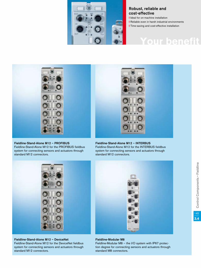
Con
trol
Com
pone
nts
• Fie
ldlin
e
145
3.4
Your benefit
Robust, reliable and cost-effectivel Ideal for on-machine installationl Reliable even in harsh industrial environmentsl Time-saving and cost-effective installation
Fieldline-Stand-Alone M12 – INTERBUSFieldline-Stand-Alone M12 for the INTERBUS fieldbus system for connecting sensors and actuators through standard M12 connectors.
Fieldline-Stand-Alone M12 – PROFIBUSFieldline-Stand-Alone M12 for the PROFIBUS fieldbus system for connecting sensors and actuators through standard M12 connectors.
Fieldline-Stand-Alone M12 – DeviceNetFieldline-Stand-Alone M12 for the DeviceNet fieldbus system for connecting sensors and actuators through standard M12 connectors.
Fieldline-Modular M8Fieldline-Modular M8 – the I/O system with IP67 protec-tion degree for connecting sensors and actuators through standard M8 connectors.

146 3.4 Control Components • Fieldline
Fieldline-Stand-Alone – PROFIBUS
Technical data RF-FLS PB M12 DI 8 M12 RF-FLS PB M12 DIO 4 M12 RF-FLS PB M12 DO 8 M12-2A RF-FLS PB M12 DIO 8 M12Digital inputsNumber 8 4 – 8 Design of inputs according to IEC 61131-2, type 1 – IEC 61131-2, type 1
Definition of switching thresholds
max. low-level voltage
ULmax < 5 V – ULmax < 5 V
min. high-level voltage
UHmin > 11 V – UHmin > 11 V
Nominal input voltage 24 V DC – 24 V DC Range –30 < UIn < +30 V DC – –30 < UIn < +30 V DC Nominal input current 5 mA – 3 mA Current flowing linearly in the range of 1 < UIn < 30 V – 1 < UIn < 30 V Delay time tOn = 3,1 ms/tOff = 4,1 ms – tOn = 3 ms; tOff = 3 ms Permissible line length to the sensor 100 m – < 30 m Digital outputs Number – 4 8 Nominal output voltage UOut – UAxx –1 V Differential voltage at INom – ≤ 1 V Nominal current INom per channel – 2 A 500 mA Total current – 8 A (observe derating) 16 A (observe derating) 4 A (observe derating) Short-circuit current – max. 22 A for 300 µs Protection – Short-circuit/overloadElectric data Supply voltage 24 V DC Range 18 to 30 V DC Power consumption at UL at 24 V DC typ. 35 mA, max. 100 mA typ. 40 mA, max. 100 mA
Power consumption at US at 24 V DC typ. 4.5 mA + sensor current, max. 700 mA typ. 3 mA, max. 700 mA typ. 10 mA + sensor current, max. 500 mA
Power consumption at UAxx at 24 V DC – 6 mA + actuator current, max. 4 A 12 mA + actuator current, max. 4 A 6 mA + actuator current, max. 4 A Transmission medium PROFIBUS-conforming copper cableTransmission rate 9.64 kbaud to 12 Mbaud autobaud selection Transmission speed 12 Mpbs Operation mode 8 bits 4 bits 8 bitsSensor connection type 2-, 3 or 4 wire connection – 2-, 3 or 4 wire connection Actuator connection type – 2-, 3 wire connection Ambient conditions Permissible temperature (operation) –25 to +60 °C Permissible temperature (storage) –25 to +85 °C Permissible air humidity 95 % Permissible atmospheric pressure (operation)
80 to 106 kPa (up to 2,000 m above MSL)
Permissible atmospheric pressure (storage)
70 to 106 kPa (up to 3,000 m above MSL)
Mechanical dataHousing dimensions (W x H x D) 60 x 161 x 44.5 mm 60 x 178 x 49.3 mm Dimension drawing (see pp. 152 – 153) Type 1 Type 2 Type 2 Type 2Weight 310 g 340 g 350 g 340 g Degree of protection IP65/IP67 according to IEC 60529 Protection class Class 3 according to VDE 0106, IEC 60536Vibration test (sinusoidal oscillations) acc. to EN 0068-2-6
5 g load in each spatial direction
Shock test according to EN 60068-2-27 30 g load, half sine wave positive and negative in each spatial direction

Con
trol
Com
pone
nts
• Fie
ldlin
e
147
3.4
Fieldline-Stand-Alone – INTERBUS
Technical data RF-FLS IB M12 DI 8 M12 RF-FLS IB M12 DIO 4 M12 RF-FLS IB M12 DO 8 M12-2A
Digital inputs
Number 8 4 –
Design of inputs according to IEC 61131-2 type 1 –
Definition of switching thresholds
max. low-level voltage ULmax < 5 V –
min. high-level voltage UHmin > 11 V –
Nominal input voltage 24 V DC –
Range –30 < UIn < +30 V DC –
Nominal input current 5 mA –
Current flowing linearly in the range of 1 V < UIn < 30 V 1 V < UIn < 30 V –
Delay time tOn = 3.1 ms/tOff = 4.1 ms –
Permissible line length to the sensor 100 m –
Digital outputs
Number – 4 8
Nominal output voltage UOut – UAxx –1 V
Differential voltage at INom – < 1 V
Nominal current INom per channel – 2 A
Total current – 8 A (observe derating) 16 A (observe derating)
Short-circuit current – max. 22 A for 300 µs
Protection – Short-circuit/overload
Electric data
Supply voltage 24 V DC
Range 18 to 30 V DC
Power consumption at UL at 24 V DC typ. 65 mA, max. 100 mA typ. 60 mA, max. 100 mA typ. 80 mA, max. 100 mA
Power consumption at US at 24 V DC 5 mA + sensor current, max. 700 mA 3.5 mA
Power consumption at UAxx at 24 V DC – 3 mA + actuator current, max. 4 A 12 mA + actuator current, max. 4 A
Transmission rate 500 kbaud
Operation mode 8 bits 4 bits 8 bits
Sensor connection type 2-, 3 or 4 wire connection –
Actuator connection type – 2-, 3 wire connection
Ambient conditions
Permissible temperature (operation) –25 to +60 °C
Permissible temperature (storage) –25 to +85 °C
Permissible air humidity 95 %
Permissible atmospheric pressure (operation) 80 to 106 kPa (up to 2,000 m above MSL)
Permissible atmospheric pressure (storage) 70 to 106 kPa (up to 3,000 m above MSL)
Mechanical data
Housing dimensions (W x H x D) 60 x 161 x 44.5 mm 60 x 178 x 49.3 mm
Dimension drawing (see pp. 152 – 153) Type 1 Type 2 Type 2
Weight 310 g 340 g 350 g
Degree of protection IP65/IP67 according to IEC 60529
Protection class Class 3 according to VDE 0106, IEC 60536
Vibration test (sinusoidal oscillations) according to EN 0068-2-6
5 g load in each spatial direction
Shock test according to EN 60068-2-27 30 g load, half sine wave positive and negative in each spatial direction

148 3.4 Control Components • Fieldline
Fieldline-Stand-Alone – DeviceNet
Technical data RF-FLS DN M12 DI 8 M12 RF-FLS DN M12 DIO 4 M12 RF-FLS DN M12 DO 8 M12-2A
Digital inputs
Number 8 4 –
Design of inputs according to IEC 61131-2, type 1 –
Definition of switching thresholds
ULmax < 5 V –
UHmin > 11 V –
Nominal input voltage 24 V DC –
Range –30 < UIn <+30 V DC –
Nominal input current 5 mA –
Current flowing linearly in the range of 1 V < UIn < +30 V DC –
Delay time tOn = 3.1 ms, tOff = 4.1 ms –
Permissible line length to the sensor < 30 m –
Digital outputs
Number – 4 8
Nominal output voltage UOut – UAxx –1 V
Differential voltage at INom – ≤ 1 V
INom per channel – 2 A
Total current – 8 A (observe derating)
Short-circuit current – max. 28 A for 150 µs
Protection – Short-circuit/overload
Electric data
Supply voltage 24 V DC
Range 18 to 30 V DC
Power consumption at UL at 24 V DC typ. 65 mA, max. 100 mA typ. 60 mA, max. 100 mA typ. 680 mA, max. 100 mA
Power consumption at US at 24 V DC 5 mA + sensor current, max. 700 mA 4.5 mA + sensor current, max. 700 mA 3.5 mA
Power consumption at UAxx at 24 V DC – 12 mA + actuator current, max. 4 A
Transmission medium Copper cable according to DeviceNet specification
Transmission rate 125 kbaud, 250 kbaud, 500 kbaud
Operation mode 8 bits 4 bits 8 bits
Sensor connection type 2-, 3 or 4 wire connection –
Actuator connection type – 2-, 3 wire connection
Ambient conditions
Permissible temperature (operation) –25 to +60 °C
Permissible temperature (storage) –25 to +85 °C
Permissible air humidity 95 %
Permissible atmospheric pressure (operation) 80 to 106 kPa (up to 2,000 m above MSL)
Permissible atmospheric pressure (storage) 70 to 106 kPa (up to 3,000 m above MSL)
Mechanical data
Housing dimensions (W x H x D) 60 x 161 x 44.5 mm 60 x 178 x 49.3 mm
Dimension drawing (see pp. 152 – 153) Type 1 Type 2 Type 2
Weight typ. 310 g typ. 340 g typ. 350 g
Degree of protection IP65/IP67 according to IEC 60529
Protection class Class 3, according to VDE 0106, IEC 60536
Vibration test (sinusoidal oscillations) according to EN 0068-2-6
5 g load in each spatial direction
Shock test according to EN 60068-2-27 30 g load, half sine wave positive and negative in each spatial direction

Con
trol
Com
pone
nts
• Fie
ldlin
e
149
3.4
Fieldline-Modular M8 – digital inputs and outputs
Technical data RF-FLM DI 8 M8 RF-FLM DIO 8/4 M8
Digital inputs
Input description 4 fixed, 4 freely selectable
Connection method 2-, 3 wire connection
Number 8
Protective circuit Reverse polarity protection
Filter time 3 ms
Input characteristic IEC 61131-2, type 1
Input voltage 24 V DC
Input voltage range, low level –30 to 5 V DC
Input voltage range, high level 13 to 30 V DC
Digital outputs
Output description – Can also be used as inputs
Connection method – 2-, 3 wire connection
Number of outputs – 4
max. output current per channel – 500 mA
Protective circuit – Short-circuit protection
Output voltage – 24 V DC
max. output current per channel – 500 mA
Electric data
Designation UL
Supply voltage 24 V DC
Supply voltage range 18 to 30 V DC, IEC 61131-2 (ripple included)
Supply current 3 A
Transmission rate 500 kbaud
Connection type M8 connector
Ambient conditions
Ambient temperature (operation) –25 to 60 °C
Ambient temperature (transport/storage) –25 to 85 °C
Permissible air humidity (operation) 5 to 95 %
Permissible air humidity (storage/transport) 10 to 95 %
Atmospheric pressure (operation) 80 to 106 kPa (up to 2,000 m above MSL)
Atmospheric pressure (transport/storage) 70 to 106 kPa (up to 3,000 m above MSL)
Mechanical data
Housing dimensions (W x H x D) 29.8 x 143 x 26.5 mm
Dimension drawing (see pp. 152 – 153) Type 4 Type 4
Weight 137 g
Drill hole spacing 133 mm
Mounting type Mounted to walls
Test section to peripherals 500 V AC
Degree of protection IP65/67
Protection class 3, VDE 0106, IEC 60536

150 3.4 Control Components • Fieldline
Technical data RF-FLM BK PB M12 DI 8 M12
Digital inputs
Connection type M12 connectors
Connection method 2-, 3 or 4 wire connection
Number of inputs 8
Protective circuit Reverse polarity protection
Filter time 3 ms
Input voltage 24 V DC
Input voltage range, low level –30 to 5 V DC
Input voltage range, high level 13 to 30 V DC
Local bus Gateway
Connection type M12 connectors, B-coded
Transmission rate 500 kbaud
Max. number of local bus users 16
Max. length of local bus 20 m
Interface
Designation PROFIBUS DP
Connection type 2 M12 connectors, B-coded
Transmission rate 9.64 to 12 Mbaud, autobauds
Address space assignment 1 to 127, adjustable
Number of pins 5
Electric data
Connection method M12 connectors
Designation UL
Supply voltage 24 V DC
Supply voltage range 18 to 30 V DC, IEC 61131-2 (ripple included)
Ambient conditions
Ambient temperature (operation) –25 to 60 °C
Ambient temperature (transport/storage) –25 to 85 °C
Permissible air humidity (storage/transport) 95 %
Atmospheric pressure (operation) 80 to 106 kPa (up to 2,000 m above MSL)
Atmospheric pressure (transport/storage) 70 to 106 kPa (up to 3,000 m above MSL)
Mechanical data
Housing dimensions (W x H x D) 70 x 178 x 50 mm
Dimension drawing (see pp. 152 – 153) Type 3
Weight 331 g
Drill hole spacing 168 mm
Mounting type Mounted to walls
Test section to peripherals 500 V AC
Degree of protection IP65/67
Protection class 3, VDE 0106, IEC 60536
Fieldline-Modular M8 – bus couplers

Con
trol
Com
pone
nts
• Fie
ldlin
e
151
3.4
Accessories
Ordering data
Type code Description
M12 cable sets
IKB0048/xxx Bus cable PROFIBUS, M12 male, straight, shielded, 5 pins, B-coded, free line end
IKB0049/xxx Bus cable PROFIBUS, M12 female, straight, shielded, 5 pins, B-coded, free line end
IKB0050/xxx Bus cable PROFIBUS, M12 male, straight, shielded, 5 pins, B-coded, M12 female, straight, shielded, 5 pins, B-coded
IKB0045/xxx Bus cable INTERBUS, M12 male, straight, shielded, 5 pins, B-coded, free line end
IKB0046/xxx Bus cable INTERBUS, M12 female, straight, shielded, 5 pins, B-coded, free line end
IKB0047/xxx Bus cable INTERBUS, M12 male, straight, shielded, 5 pins, B-coded, M12 female, straight, shielded, 5 pins, B-coded
IKB0042/xxx Bus cable DeviceNet, M12 male, straight, shielded, 5 pins, B-coded, free line end
IKB0043/xxx Bus cable DeviceNet, M12 female, straight, shielded, 5 pins, B-coded, free line end
IKB0044/xxx Bus cable DeviceNet, M12 male, straight, shielded, 5 pins, B-coded, M12 female, straight, shielded, 5 pins, B-coded
IKL0267/xxx Voltage cable, female, straight, unshielded, M12 A-coded, 4 pins, open line end
IKL0268/xxx Voltage cable, male, straight, unshielded, M12 A-coded, female, straight, unshielded, M12 A-coded, 4 pins
RKB0003/xxx Voltage cable, Y-connector, straight, M12 on 2 x female, straight, M12
M12 connectors
RBS0001 M12 connector, male, straight, shielded, with screwed connection, 5 pins, B-coded
RBS0002 M12 connector, female, shielded, with screwed connection, 5 pins, B-coded
RBS0003 M12 connector, male, straight, unshielded, A-coded, 4 pins
RBS0004 M12 connector, female, straight, unshielded, A-coded, 4 pins
RBS0005 M12 connector – insulation displacement, male, straight, unshielded, A-coded, 4 pins
RBS0006 M12 connector – insulation displacement, female, straight, unshielded, A-coded, 4 pins
RBS0008 M12 connector, male, shielded, with screwed connection, 5 pins, A-coded
M12 accessories
INS0762/CNN M12 terminating resistor, PROFIBUS, B-coded, 5 pins
M8 cable sets
RKB0014/xxx Local bus cable, M8 male, straight, free line end
RKB0015/xxx Local bus cable, M8 female, straight, free line end
RKB0016/xxx Local bus cable, M8 female, straight, M8 male, straight
RKB0017/xxx Voltage cable, M8 female, straight, free line end
M8 accessories
FLM ADAP M12/M8 Adapter, M12/M8
xxx = cable length in meters

152 3.4 Control Components • Fieldline
Fieldline-Stand-Alone M12
60 44.5
161
60 49.3
178
60 44.5
161
60 49.3
178
Type 1
Type 2

Con
trol
Com
pone
nts
• Fie
ldlin
e
153
3.4
Fieldline-Stand-Alone M8
70 49.3
178
29.8
143
26.5 6
70 49.3
178
29.8
143
26.5 6
Type 3
Type 4

154 3.5 Control Components • IndraWorks
Rexroth IndraWorks allows you to solve all tasks in a uniform and intuitive software environment – from project planning and programming to visualization and diagnostics.
The uniform engineering framework IndraWorks is consistently available for all systems from the Rexroth Automation House. You, as user, profit from the fast and transparent access to all functions and system data of the automation components. The standard-ized tools and interfaces help you to solve all engineering tasks centrally with a single software.
Your benefits• Available for all systems and
solutions from the Rexroth Automation House
• Integrated framework for all engineering tasks
• Consistent operating environment for project planning, programming, visualization and diagnostics
• Central project management with intuitive system navigation
• Intelligent operation with wizard support
• Comprehensive online help
IndraWorks – the Tool for all Engineering Tasks
• Uniform programming according to the PLC standard IEC 61131-3
• PLCopen-conforming function block and technology libraries
• Standardized interfaces for communication
• Transparent access to all system components
• Integrated FDT/DTM interface for integration of the DTM of third party manufacturers
Re
xroth IndraWorks
Engineering Oper
atin
g
Visualization
Service
Operation
Add-ons
Parameterization
Tools
Project development
Programming

Con
trol
Com
pone
nts
• Ind
raW
orks
155
3.5
Your benefit
IndraWorks – the universal engineering frameworkl One tool for all automation tasksl Goal reached quickly through startup guide l Offline configuration of projectsl Comfortable programming environment
Operation and visualization
Apart from providing engineering functions, IndraWorks is also an HMI front end for various applications. IndraWorks allows you to project machine- or system-specific screens. Using the project development tool WinStudio, you can easily integrate standard screens in the user interface. In addition, you can easily integrate prefabricated ActiveX controls in your HMI applications.
Tools
The tools for all engineering tasks are integrated in IndraWorks. Additional solution-specific tools are consistently available in the software framework. Using menus or the project tree, you can access, for example, CamBuilder for creating cams, simulation tools, firmware management, or system-com-patible programming editors.
Project development
The overall system is uniformly and consistently projected for all solu-tions. User and multi-project manage-ment are available in all instances. The project and device explorers provide access to all control compo-nents. With its clearly organized dia-log boxes, IndraWorks guides you intuitively through the configuration of your system.
Parameterization
The project explorer provides access to all data of the system compo-nents. Wizards guide you through all engineering steps, interactively and in sequence. Control and drive options or motion axes can be parameterized easily and clearly, even offline. I/O peripherals and communication inter-faces can be configured through the integrated configurators. The online help provides you with all necessary information.
Programming
The IndraLogic runtime system that is integrated in all solutions is consistent-ly programmed in IndraWorks. The complete language scope specified in IEC 61131-3 is available. System-specific additional functions, such as motion blocks according to PLCopen or technology blocks, can be quickly and transparently implemented in your logic programs.
Diagnostics
Comprehensive tools are implemented in Indraworks to facilitate startup or service activities. Such tools cover the complete range from four-channel oscilloscope and logic analyzer through debugging functions of the PLC logic to manifold status messages and system diagnostics. To provide com-prehensive detailed information on controls, drives, HMI, and peripherals, you just have to press a button.

156 3.5 Control Components • IndraWorks
IndraWorks
1. IndraWorks Engineering
1.1 General information
1.1.1 Multilingualism of framework l
1.1.2 Multilingualism of projects l
1.1.3 Export/import of texts of the PLC projects l
1.1.4 Firmware management l
1.1.5 Deactivating/parking drives in the project ®
1.1.6 Switching between online and offline modes l
1.1.7 Automatic system monitoring units l
1.1.8 Real-time logic analyzer l
1.1.9 Oscilloscope function l
1.1.9.1 Graphical output with zoom function l
1.1.9.2 Display of signal values of drives l
1.1.9.3 Scaling l
1.1.9.4 Measuring with/without trigger l
1.1.10 System-specific expansions ®
1.2 Configuration and project planning
1.2.1 System configurator l
1.2.2 Device library for controls, drives, visualization, peripherals l
1.2.3 Assistants for commissioning of controls and drives l
1.2.4 Project navigator l
1.2.5 I/O configurator l
1.2.6 Fieldbus configurator l
1.2.7 Project archiving l
1.2.8 Parameter monitor for controls and drives l
1.2.9 Offline parameterization of controls and drives l
1.2.10 System-specific expansions ®
1.2.11 Cams editor ®
1.2.11.1 Graphical creation of cams l
1.2.11.2 Kinematic laws according to VDI 2143 l
1.2.11.3Interpolation point calculation: linear, square, sinusoidal,
polynomial up to 8th degree, trapezoidal l
1.2.11.4 Analytic cam disks for motion profiles l
1.2.11.5 Wizards for specific applications l
1.2.11.6 Import/export l
1.3 PLC programming
1.3.1 Graphical editors
1.3.1.1 Sequential function chart (SFC) l
1.3.1.2 Ladder diagram (LD) l
1.3.1.3 Function Block Diagram (FBD) l
1.3.1.4 Continuous Function Chart (CFC) l
1.3.2 Textual editors
1.3.2.1 Instruction List (IL) l
1.3.2.2 Structured Text (ST) l
1. IndraWorks Engineering
1.3.3 Data types
1.3.3.1 Standard according to IEC 61131-3 incl. LREAL l
1.3.3.2 User-defined: arrays, structures, enumeration, alias, pointer l
1.3.4 Special editor features
1.3.4.1 Syntax coloring l
1.3.4.2 Multiple undo/redo l
1.3.4.3 Context-sensitive input help l
1.3.4.4 Context-sensitive menus l
1.3.4.5 Auto-declaration l
1.3.5 Library management l
1.3.6 Libraries
1.3.6.1 General information l
1.3.6.2 System ®
1.3.6.3 PLCopen ®
1.3.6.4 Technology functions ®
1.3.7 Online debugging/commissioning l
1.3.7.1 Monitoring of variables (trace) l
1.3.7.2 Forcing of variables and variable sets l
1.3.7.3 Project debugging l
1.3.7.4 Power flow (sequential check) l
1.3.7.5 Online exchange of function blocks l
1.3.7.6 Offline simulation of PLC variables l
1.3.7.7 Parameter monitor l
1.3.8 Offline programming l
1.4 CNC programming ®
1.4.1 Parts programming l
1.4.2 High-level language programming l
1.4.3 Graphical NC programming l
1.4.4 Graphical NC simulation l
1.5 RC programming ®
1.5.1 Textual robot-control programming l
1.5.2 Parameterization of kinematics l
1.6 HMI project planning ®
1.6.1 Project development tool WinStudio (Lite, 500 variables) l
1.6.2WinStudio extensions (1,500/4,000/64,000/512,000
variables)°
1.7 Kinemtaic simulation °
2. IndraWorks Operation
2.1 Operation and visualization ®
2.2 Configurable user interfaces with all standard functions ®
2.3 Configurable user screens ®
2.4 Automatic system monitoring units ®
2.5 Instructions and error messages in plaintext ®
2.6 System-specific expansions °
l°®
DefaultOptionalSystem-relating

Con
trol
Com
pone
nts
• Ind
raW
orks
157
3.5
Ordering data
Order code Description
SWA-IWORKS-D**-xxVRS-D0-CD650-COPY IndraWorks for drive system IndraDrive
SWA-IWORKS-IL*-xxVRS-D0-CD650 IndraWorks for all IndraLogic systems
SWA-IWORKS-ML*-xxVRS-D0-CD650 IndraWorks for IndraMotion MLC system
SWA-IWORKS-MTX-xxVRS-D0-CD650 IndraWorks for IndraMotion MTX system
SWA-IWORKS-MTX-xxVRS-D0-CD650-OPDENG Standard CNC operating and programming software (operation and engineering)
incl. WinStudio Lite Runtime and Editor (DE/EN)
SWA-IWORKS-MTX-xxVRS-D0-CD650-OPD Standard CNC operating software (operation) incl. WinStudio Lite Runtime (DE/EN)
SWA-IWORKS-MTX-xxVRS-D0-CD650-COM Communication interface for customer-specific user interfaces (DE/EN)
SWA-IWORKS-MTX-xxVRS-D0-CD650-SIMULATORIndraWorks for IndraMotion MTX-CNC systems,
offline and remote programming, MTX simulator (DE/EN)
Software options
SWS-IWORKS-V3D-NNVRS-D0 I IndraWorks 3D-Viewer for kinematic simulation
SWS-IWORKS-REM-xxVRS-D0-CD650 IndraWorks add-on for PC-based remote maintenance
Documentations
Order code Description
DOK-IWORKS-HMI*Vxx****AWxx-EN-P Application description of IndraWorks visualization
DOK-IWORKS-IREMOTE*Vxx-AWxx-EN-P Application description of IndraWorks remote maintenance
xx = software/firmware version

158 3.5 Control Components • IndraWorks
The graphics-based software tool CamBuilder facilitates the creation of cams on the PC. With the help of dialog-controlled inputs, all require-ments and special features of appli-cations, such as cross cutters, feed axes or printing length corrections, are implemented quickly and reliab-ly. They can then be transferred to our drive controllers or controls with only a few inputs.
CamBuilder is an optional tool that is integrated in the IndraWorks engineer-ing framework. But CamBuilder is also available as a stand-alone tool and can be used independently of the controls and drive systems used.
Your benefits• Easy creation of cams with the help
of graphical objects• Convenient editing of existing cams• Editing of several cams at the same
time• Utilization of motion laws according
to VDI 2143• Transmitting and receiving of cams
in Rexroth drives and controls• Automatic display of position,
acceleration, velocity, and jerk• Support for frequent requirements
provided by wizards
CamBuilder – Intuitive Software Tool for Cam Creation
• Import of point tables for partial areas of the cam
• Automatic detection and calcula-tion of marginal conditions of the cam
• Zoom functionality• Switching between standardized
and evaluated views• Import/export functionality with
various formats
CamBuilder – software tool for fast and easy creation of cams

Con
trol
Com
pone
nts
• Ind
raW
orks
159
3.5
Ordering data
Order code Description
CamBuilder Stand-Alone
SWA-CAM*PC-INB-xxVRS-D0-CD650 Cam editor CamBuilder
CamBuilder for IndraWorks (optional)
SWS-IWORKS-CAM-xxVRS-D0 Cam editor CamBuilder in IndraWorks
xx = software/firmware version
Functions
1 General information
1.1 Creation of cams l
1.2 Creation of segmented motion profiles l
1.3 Project explorer l
1.4 Section editor l
1.5 Graphical output of the calculated cam l
1.6 Graph manager l
1.7 List of extreme values of the cam l
1.8 Sections list l
1.9 Representation of profile points of the cam l
1.10 Profile point editor l
1.11 Agents for the creation of application-specific cams l
1.12 Data management incl. import/export l
2 Application-related wizards
2.1 Cross cutter l
2.2 Feeder l
2.3 Printing length correction l
3 Mathematical functions
3.1 Linear rest l
3.2 Straightline (linear interpolation) l
3.3 Quadratic parabola l
3.4 2nd degree polynomial l
Functions
3.5 3rd degree polynomial l
3.6 4th degree polynomial l
3.7 5th degree polynomial l
3.8 6th degree polynomial l
3.9 7th degree polynomial l
3.10 8th degree polynomial l
3.11 Inclined sine line l
3.12 Simple sine line l
3.13 Modified sine line l
3.14 Modified acceleration trapezoid l
3.15 Linear V-cam l
3.16 2nd degree V-cam l
3.17 2nd degree A-cam l
3.18 Linear A-cam l
3.19 Analytic G-G l
3.20 Analytic G-G (5th degree) l
3.21 Analytic G-R (5th degree) l
3.22 Analytic R-G (5th degree) l
3.23 Analytic R-R (5th degree) l
3.24 Analytic R-R (inclined sine line) l
3.25 Import of a point table l
3.26 User-defined kinematic laws l

160 3.5 Control Components • IndraWorks
WinStudio –for More Transparency in Your ProductionWinStudio is the innovative visuali-zation module of the IndraWorks software framework for consistent engineering and user-friendly ope-ration. WinStudio allows you to create your individual applications quickly, easily and efficiently – with one tool for all applications.
Together with the embedded PCs and the PC-based solutions from Rexroth, WinStudio ensures maximum function-ality and optimum performance. The flexible licensing model is available in development and runtime versions. Needing only one development version, you can adapt your applications as often as desired and use them with various runtime versions. This design allows continuous improvement to your machines and is also very cost effective.
Your benefits• Less project development and
maintenance work through a uniform visualization software
• Clearly organized selection of objects via the project explorer
• Easy creation of screens with comprehensive libraries
• Dynamic generation of web sites• Easy project planning without
knowledge of high-level languages• Graded software packages for
individual adaptation• UNICODE characters• Auto-screen scaling
WinStudio – easy and effective project planning in the development environ-ment by drag-and-drop

Con
trol
Com
pone
nts
• Ind
raW
orks
161
3.5
Type WinStudio
lite
WinStudio
1.5 k
WinStudio
4 k
WinStudio
64 k
WinStudio
512 k
WinStudio
lite
WinStudio
1.5 k
WinStudio
4 kDevelopment license Windows XP/2000/NT –Runtime license Windows XP/2000/NT Windows CEVariables 500 1,500 4,000 64,000 512,000 500 1,500 4,000Array size 256 512 1,024 16,384 256 512Classes 32 64 512 32Open screens 1 Unlimited 1Network connections – 2 4 32 Open – 1Recipe handling – l – l
ODBC l –Mathematics l l
Alarm/events – l – l
History – l – l
Driver 1 3 5 8 1 3OPC server – l – l
OPC client l l
TCP/IP server l l
TCP/IP client – l – l
DDE server and client – l –Tags database l l
Web client – 1/4/8 – –l Default
Ordering dataOrder code Description Editor licenses WinNT/2K/XP SWS-WINSTU-RUD-xxVRS-D0-1K5 RUD/1.5K SWS-WINSTU-RUD-xxVRS-D0-4K RUD/4K SWS-WINSTU-RUD-xxVRS-D0-64K RUD/64K SWS-WINSTU-RUD-xxVRS-D0-512K RUD/512K Runtime licenses WinNT/2K/XP SWS-WINSTU-RUN-xxVRS-D0-1K5 RUN/1.5K SWS-WINSTU-RUN-xxVRS-D0-4K RUN/4K SWS-WINSTU-RUN-xxVRS-D0-64K RUN/64K SWS-WINSTU-RUN-xxVRS-D0-512K RUN/512K Runtime licenses WinNT/2K/XP with access to web clients SWS-WINSTU-RUW-xxVRS-D0-64K01CL RUN/64 K – 1 web client SWS-WINSTU-RUW-xxVRS-D0-64K04CL RUN/64 K – 4 web clients SWS-WINSTU-RUW-xxVRS-D0-64K08CL RUN/64 K – 8 web clients Runtime licenses for CE devicesSWS-WINSTU-RUN-xxVRS-D0-WCE1K5 RUN/1.5 K – CE devicesSWS-WINSTU-RUN-xxVRS-D0-WCE4K RUN/4 K – CE devicesData carrier SWA-WINSTU-RUD-xxVRS-D0-CD650 Software CD Dongle B-AC USB dongle USB dongle B-AC LPT dongle LPT dongle Documentation Description DOK-CONTRL-WIS*PC**Vxx-KBxx-EN-P WinStudio xx = software/firmware version

162 3.5 Control Components • IndraWorks
VI-Composer is an easy but power-ful project development tool for the visualization and parameterization of system-related data of the IndraControl VCP/VCH devices. In this convenient development envi-ronment, you can efficiently create your individual application, based on the usual Windows look-and-feel. The programming result can then be used on the various IndraControl VCP/VCH devices as often as desired.
The fully graphical VI-Composer software allows you to develop pro-jects for IndraControl VCP/VCH devices according to the WYSIWYG (What You See Is What You get) prin-ciple, text, variables and graphics are immediately represented just as they will be displayed by the IndraControl VCP/VCH devices. Predefined masks and comprehensive graphics libraries with numerous industry-compatible screen objects facilitate the creation of your applications. Based on Windows- conforming operation, you describe all variables depending on the particu-lar control, whereas masks, graphics, recipes and the like can be created independently of any control. VI-Composer provides direct access to the IndraWorks database and, thus, to all variables of the controls and drives. The performance is completed by comprehensive help functions.
VI-Composer – the Comfortable Project Development Software for Easy Visualization and Parameterization
Your benefits• Language management of
the application with up to 16 languages
• Messaging and recording system• Font editor for creating your own
character sets• Easy graphics incorporation via
OLE• Direct access to all control and
drive variables• Project and firmware download for
reloadable functions• Integrated creation of documenta-
tion and online help• Predefined masks, curves and bar
graphs• Definition of free menu structures• Screen elements: texts, variables,
graphics, switches, buttons, drop-down list boxes, tables, etc.
VI-Composer – efficient programming of your application in a convenient development environment

Con
trol
Com
pone
nts
• Ind
raW
orks
163
3.5
Type VI-Composer
Development license for operation system Windows XP/2000/NT
Firmware Integrated in all VCP devices
Variables 65,535
Connections Download: Ethernet
Communication Serial, PROFIBUS DP, DeviceNet
Messages 9,999
Messaging buffer 3,000
Protocol driver 3S serial, Rexroth BUEP19E, BRC symbolics, DeviceNet, IndraLogic, PROFIBUS DP
Support of Asian characters l
Print reports l
Firmware download l
Application upload l
Recipe handling l
Messaging and recording system l
Online help l
Integrated creation of documentation l
Variables represented by curves and bar graphs l
Translation support for multilingual projects l
Graphics incorporation via OLE With terminals with graphics capability
Development license German/English
l Default
Ordering data
Order code Description
SWA-VIC*PC-INB-xxVRS-D0-CD650 VI-Composer
Documentation
Order code Description
DOK-SUPPL*-VIC*BEDIEN*-AWxx-EN-P Operating instructions
xx = software/firmware version

04 Glossary164
C
Glossary
F
HI
DE
Cam controller Function emitting a binary signal in relation to the current position or to the distance traveled. In the past, this function was realized mechanically. Today, it is executed by programmable electronic controls.
Cams, electronic The desired position of the slave axis is calculated from the actual position of the master axis on the basis of a mathematical “cam disk” function.
CNC Computerized Numerical Control. Digital control for machine tools.
DeviceNet CANbased communication system for linking industrial automation components to higherorder control equipment in a network.
Electronic gear Electronic simulation of a mechanical gear by software.
Fieldbus Conducted communication system which interconnects control units, sensors and actuators. Standardized through IEC 61508.
Firmware Devicespecific software for automation components. Not exchangeable when filed to a readonly memory, or on removable memory media such as compact flash.
Function library Collection of function blocks or functions, for example according to IEC 611313 or PLCopen.
HMI Human Machine Interface. System for operating and visualizing machines and plants.
IndraControl L Control platform from the Rexroth Automation House.
IndraControl V IPC and visualization platform (HMI) from the Rexroth Automation House.
IndraDrive Drive platform from the Rexroth Automation House.
M
IndraDyn Motor platform from the Rexroth Automation House.
IndraLogic Consistent PLC platform according to IEC 611313 from the Rexroth Automation House.
IndraLogic L Controllerbased PLC system family from the Rexroth Automation House.
IndraLogic V PCbased and embeddedPCbased PLC system family from the Rexroth Automation House.
IndraMotion System family of integrated motionlogic solutions from the Rexroth Automation House.
IndraMotion MLC Controllerbased system solution with integrated motion logic from the Rexroth Automation House.
IndraMotion MLD Drivebased system solution with integrated motion logic from the Rexroth Automation House.
IndraMotion MLP PCbased system solution with integrated motion logic from the Rexroth Automation House.
IndraMotion MTX System family of CNC solutions from the Rexroth Automation House.
IndraWorks Software framework for engineering and operation, consistent for all solutions from the Rexroth Automation House.
I/O Input/output – I/O are discrete interfaces for transmitting or receiving digital or analog signals.
IPC Industrial PC – sturdy design of a standard PC, which meets the conditions of an industrial environment.
Master Central bus user controlling access to the bus, while lowerorder users operate as slaves.

Glo
ssar
y
165
4
O
S
V
P
U
Master axis Position or velocity command value of a master for the following slave axes.
Motion control Intelligent and complex guidance of the movements of multiaxis systems. Control and drive functionalities are integrated in a single system.
Motion logic Automation software or firmware with integrated motion control and PLC logic.
Motion profile Method for describing a motion by velocity, time an position.
OPC OLE for Process Control, communication standard for components in the automation sector, to ensure smooth standardized data exchange between controls, operating and visualization systems, field devices and office applications of various manufacturers.
PLC A programmable logic controller, PLC or programmable controller is a small computer used for automation of realworld processes, such as control of machinery on factory assembly lines. Where older automated systems would use hundreds or thousands of relays and cam timers, a single PLC can be programmed as a replacement. Programmable controllers were initially adopted by the automotive manufacturing industry, where software revision replaced the rewiring of hardwired control panels.
PLCopen International community of interests, established by control manufacturers, software companies and institutes (independent of manufacturers and products). In compliance with the PLC standard IEC 611313, technical committees define standards facilitating an increase in the efficiency of application software.
PROFIBUS Process Field Bus – today, mainly serial field busses are used as communication systems for exchanging information among automation systems as well as with the connected distributed field devices.
Safety on Board Integrated safety solutions from the Rexroth Automation House.
SERCOS III Third SERCOS generation – further development of the existing SERCOS interface standard according to IEC/EN 61491, based on standard Ethernet. In this generation, the known SERCOS mechanisms, such as motioncontrol profiles, telegram structure and hardware synchronization, have been applied for hard realtime communication.
SERCOS interface Serial Realtime Communications Standard Interface – open and serial realtime communication standard for highprecision motioncontrol applications, designed by leading manufacturers of numerically controlled drives.
Slave Network user not allowed to participate in data exchange except when addressed by the master.
UPS Uninterruptible Power Supply – ensures continuous user supply for a certain time in the event of a power failure.
User library Collection of userspecific function blocks or functions in the form of a downloadable PLC library.
User program Applicationspecific software.
Virtual master axis
Calculated position or velocity command value of a virtual master for the following slave axes.


Bosch Rexroth AGElectric Drives and ControlsPostfach 13 5797803 Lohr, DeutschlandBgm.-Dr.-Nebel-Str. 297816 Lohr, DeutschlandTel. +49 9352 40-0Fax +49 9352 40-4885www.boschrexroth.com
72 604 AE/07-03 – A1 – HW R911320438© Bosch Rexroth AG 2007Subject to modificationPrinted in Germany
The specified data is only intended to describe the product. Since our products are subject to continuous further development, our information must not be understood as a guaranteed property or suitability for a special applica-tion. This information does not relieve users from performing their own evaluations and tests. Please note that our products are subject to a natural wear and ageing process.
HydraulicsElectric Drivesand Controls
Linear Motion andAssembly Technologies Pneumatics Service
Bosch Rexroth AGElectric Drives and ControlsP.O. Box 13 5797803 Lohr, GermanyBgm.-Dr.-Nebel-Str. 297816 Lohr, GermanyPhone +49 9352-40-0Fax +49 9352-40-4885www.boschrexroth.com
Presented by: