automation system s7-400 configuration and use · 7.1 step 7 - the programming ... 7.2 programming...
TRANSCRIPT
Preface, Contents
SIMATIC - an Overview1
CPUs of the S7-4002
Signal Modules of the S7-4003
Technological Functions of theS7-400
4
Interfaces, Networks and DataCommunication for the S7-400
5
Configuration Variants of theS7-400
6
Programming the S7-4007
Operator Control and Monitoringwith the S7-400
8
Standards, Certificates andApprovals
9
Further Information10
Index
Edition 10/2005A5E00442711-02
Automation System S7-400Configuration and Use
System Description
SIMATIC
This manual has the order number:6ES7498-8AA00-8BB0
!Danger
indicates that death or severe personal injury will result if proper precautions are not taken.
!Warning
indicates that death or severe personal injury may result if proper precautions are not taken.
!Caution
with a safety alert symbol indicates that minor personal injury can result if proper precautions are nottaken.
Caution
without a safety alert symbol indicates that property damage can result if proper precautions are nottaken.
Notice
indicates that an unintended result or situation can occur if the corresponding notice is not taken intoaccount.
If more than one degree of danger is present, the warning notice representing the highest degree ofdanger will be used. A notice warning of injury to persons with a safety alert symbol may also include awarning relating to property damage.
Qualified PersonnelThe device/system may only be set up and used in conjunction with this documentation. Commissioningand operation of a device/system may only be performed by qualified personnel. Within the context of thesafety notices in this documentation qualified persons are defined as persons who are authorized tocommission, ground and label devices, systems and circuits in accordance with established safetypractices and standards.
Prescribed UsageNote the following:
!Warning
This device and its components may only be used for the applications described in the catalog or thetechnical description, and only in connection with devices or components from other manufacturers whichhave been approved or recommended by Siemens.
Correct, reliable operation of the product requires proper transport, storage, positioning and assembly aswell as careful operation and maintenance.
TrademarksAll names identified by ® are registered trademarks of the Siemens AG.The remaining trademarks in this publication may be trademarks whose use by third parties for their ownpurposes could violate the rights of the owner.
Disclaim of LiabilityWe have reviewed the contents of this publication to ensure consistency with the hardware and softwaredescribed. Since variance cannot be precluded entirely, we cannot guarantee full consistency. However,the information in this publication is reviewed regularly and any necessary corrections are included in sub-sequent editions.
Safety GuidelinesThis manual contains notices you have to observe in order to ensure your personal safety, as well as toprevent damage to property. The notices referring to your personal safety are highlighted in the manual bya safety alert symbol, notices referring to property damage only have no safety alert symbol. The noticesshown below are graded according to the degree of danger.
Copyright E Siemens AG 2005Technical data subject to change
SIEMENS AGAutomation and DrivesPostfach 484890437 NÜRNBERGGERMANY
A5E00442711-0210/2005
iiiAutomation System S7-400 Configuration and UseA5E00442711-02
Preface
Purpose of this System Description
The information in this system description is intended to help you do the following:
• Get an overview of the S7-400 automation system.
• Decide if the S7-400 automation system is the optimal controller for yourautomation task.
• Decide which S7-400 CPU and modules are the best solution for you specialapplication.
When putting a SIMATIC S7-400 into operation, you will need the documentationpackage, ”S7-400 Programmable Controller”.
Contents of this System Description
This system description provides you with an overview of the S7-400 automationsystem.
The system description includes the following topics:
• Features of the S7-400
• Communication with the S7-400
• Configuration Options for the S7-400
• Programming the S7-400
• Operator Control and Monitoring with the S7-400
When putting a SIMATIC S7-400 into operation, you will need the documentationpackage, ”Automation System S7-400”.
Required Level of Knowledge
General knowledge about the field of automation engineering is required tounderstand the system description.
You also need basic knowledge about the use of computers or resources similar toPCs (e. g. programming devices) running under the Windows 2000 or XPoperating systems.
Scope of this System Description
This system description applies to the S7-400 automation system. It reflects thetechnological level of development applicable in the year of publication.
Preface
ivAutomation System S7-400 Configuration and Use
A5E00442711-02
Approvals
Chapter 9 provides detailed information about approvals and standards.
Position in the Information Landscape
This system description can be separately ordered with the order number6ES7498-8AA00-8AB0.
Guide
You can quickly access specific information in the manual by using the followingaids:
• At the start of the system description you will find a complete table of contentsand a list of the figures and tables that appear in the publication.
• At the end of the system description you will find a comprehensive index to helpyou quickly find the information you are looking for.

vAutomation System S7-400 Configuration and UseA5E00442711-02
Contents
1 SIMATIC S7 - an Overview 1-1. . . . . . . . . . . . . . . . . . . . . . . . . . . . . . . . . . . . . . . . . . . . . . .
1.1 SIMATIC S7 - a Few Highlights 1-2. . . . . . . . . . . . . . . . . . . . . . . . . . . . . . . . . . .
1.2 What are the features of the S7-400? 1-4. . . . . . . . . . . . . . . . . . . . . . . . . . . . . .
1.3 An Overview of S7-400 Components 1-6. . . . . . . . . . . . . . . . . . . . . . . . . . . . . . .
1.4 S7-400 - Configuration Variants 1-8. . . . . . . . . . . . . . . . . . . . . . . . . . . . . . . . . . .
2 CPUs of the S7-400 2-1. . . . . . . . . . . . . . . . . . . . . . . . . . . . . . . . . . . . . . . . . . . . . . . . . . . . .
2.1 CPUs of the S7-400 - System-wide Compatibility 2-2. . . . . . . . . . . . . . . . . . . .
2.2 Performance Characteristics of the CPUs 2-6. . . . . . . . . . . . . . . . . . . . . . . . . . .
2.3 Memory Concept 2-9. . . . . . . . . . . . . . . . . . . . . . . . . . . . . . . . . . . . . . . . . . . . . . . .
2.4 Multicomputing 2-10. . . . . . . . . . . . . . . . . . . . . . . . . . . . . . . . . . . . . . . . . . . . . . . . . .
2.5 Configuration in Run 2-11. . . . . . . . . . . . . . . . . . . . . . . . . . . . . . . . . . . . . . . . . . . . .
2.6 Clock Synchronicity 2-12. . . . . . . . . . . . . . . . . . . . . . . . . . . . . . . . . . . . . . . . . . . . . .
2.7 The CPUs S7-400H for Fault-tolerant Controllers 2-13. . . . . . . . . . . . . . . . . . . .
2.8 CPU 416F for Fail-safe Controlling (Distributed Safety) 2-18. . . . . . . . . . . . . . .
2.9 The CPUs 41xH for Fail-safe and Fault-tolerant Controllers(F/FH Systems) 2-20. . . . . . . . . . . . . . . . . . . . . . . . . . . . . . . . . . . . . . . . . . . . . . . . .
3 Signal Modules of the S7-400 3-1. . . . . . . . . . . . . . . . . . . . . . . . . . . . . . . . . . . . . . . . . . . .
3.1 Signal Modules 3-2. . . . . . . . . . . . . . . . . . . . . . . . . . . . . . . . . . . . . . . . . . . . . . . . .
3.2 Assigning Parameters to Signal Modules 3-3. . . . . . . . . . . . . . . . . . . . . . . . . . .
3.3 Addressing Signal Modules 3-4. . . . . . . . . . . . . . . . . . . . . . . . . . . . . . . . . . . . . . .
3.4 Overview of the Performance Characteristics of the Signal Modules 3-5. . . .
4 Technological Functions of the S7-400 4-1. . . . . . . . . . . . . . . . . . . . . . . . . . . . . . . . . . .
4.1 S7-400 - The Right Solution for Every Technological Task 4-2. . . . . . . . . . . . .
4.2 Function Modules - the Specialists 4-3. . . . . . . . . . . . . . . . . . . . . . . . . . . . . . . . .
4.3 Counting with the FM 450-1 4-5. . . . . . . . . . . . . . . . . . . . . . . . . . . . . . . . . . . . . . .
4.4 Controlled Positioning with the FM 451 4-6. . . . . . . . . . . . . . . . . . . . . . . . . . . . .
4.5 Cam Controlling with the FM 452 4-7. . . . . . . . . . . . . . . . . . . . . . . . . . . . . . . . . .
4.6 Controlled Positioning with the FM 453 4-8. . . . . . . . . . . . . . . . . . . . . . . . . . . . .
4.7 Controlling with the FM 455 4-9. . . . . . . . . . . . . . . . . . . . . . . . . . . . . . . . . . . . . . .
4.8 High-dynamic Closed-loop Positioning with the FM 458-1 DP 4-11. . . . . . . . . .
4.9 Software Solutions 4-13. . . . . . . . . . . . . . . . . . . . . . . . . . . . . . . . . . . . . . . . . . . . . .
Contents
viAutomation System S7-400 Configuration and Use
A5E00442711-02
5 Interfaces, Networks and Data Communication for the S7-400 5-1. . . . . . . . . . . . .
5.1 The Right Solution for Every Communication Task. 5-2. . . . . . . . . . . . . . . . . .
5.2 Interfaces 5-3. . . . . . . . . . . . . . . . . . . . . . . . . . . . . . . . . . . . . . . . . . . . . . . . . . . . . .5.2.1 MPI - the Interface with Numerous Functions 5-3. . . . . . . . . . . . . . . . . . . . . . .5.2.2 I/O Interface via PROFIBUS DP 5-6. . . . . . . . . . . . . . . . . . . . . . . . . . . . . . . . . . .5.2.3 I/O Interface via PROFINET IO 5-8. . . . . . . . . . . . . . . . . . . . . . . . . . . . . . . . . . .5.2.4 From point-to-point: CP 440, CP441-1 and CP 441-2 5-11. . . . . . . . . . . . . . . . .
5.3 Data Exchange via Communication Functions 5-12. . . . . . . . . . . . . . . . . . . . . . .
6 Configuration Variants of the S7-400 6-1. . . . . . . . . . . . . . . . . . . . . . . . . . . . . . . . . . . . .
6.1 The Structural Design of the S7-400 - Simple and Modular 6-2. . . . . . . . . . . .
6.2 An Overview of S7-400 Components 6-3. . . . . . . . . . . . . . . . . . . . . . . . . . . . . . .
6.3 Connection System of S7-400 Signal Modules 6-5. . . . . . . . . . . . . . . . . . . . . .
6.4 S7-400 Assembly in a Rack 6-7. . . . . . . . . . . . . . . . . . . . . . . . . . . . . . . . . . . . . . .
6.5 Segmented and Split Rack 6-8. . . . . . . . . . . . . . . . . . . . . . . . . . . . . . . . . . . . . . .
6.6 S7-400 Assembly in Multiple Racks 6-10. . . . . . . . . . . . . . . . . . . . . . . . . . . . . . . .
6.7 Mounting Dimensions of an S7-400 Assembly 6-13. . . . . . . . . . . . . . . . . . . . . . .
6.8 Grounded / Ungrounded S7-400 Configurations 6-15. . . . . . . . . . . . . . . . . . . . .
6.9 Utilities for Configuring and Assigning Parameters to anS7-400 Assembly 6-16. . . . . . . . . . . . . . . . . . . . . . . . . . . . . . . . . . . . . . . . . . . . . . .
7 Programming the S7-400 7-1. . . . . . . . . . . . . . . . . . . . . . . . . . . . . . . . . . . . . . . . . . . . . . . .
7.1 STEP 7 - the Programming Package for S7-400 7-2. . . . . . . . . . . . . . . . . . . . .
7.2 Programming Devices for SIMATIC S7 7-4. . . . . . . . . . . . . . . . . . . . . . . . . . . . .
7.3 Convenient Testing and Diagnostic Options 7-5. . . . . . . . . . . . . . . . . . . . . . . . .
8 Operator Control and Monitoring with the S7-400 8-1. . . . . . . . . . . . . . . . . . . . . . . . .
8.1 Convenient Operator Control and Monitoring of Complex Processeswith SIMATIC HMI 8-2. . . . . . . . . . . . . . . . . . . . . . . . . . . . . . . . . . . . . . . . . . . . . . .
9 Standards, Certificates and Approvals 9-1. . . . . . . . . . . . . . . . . . . . . . . . . . . . . . . . . . .
9.1 Standards, Certificates and Approvals 9-2. . . . . . . . . . . . . . . . . . . . . . . . . . . . . .
10 Further Information 10-1. . . . . . . . . . . . . . . . . . . . . . . . . . . . . . . . . . . . . . . . . . . . . . . . . . . . .
Index Index-1. . . . . . . . . . . . . . . . . . . . . . . . . . . . . . . . . . . . . . . . . . . . . . . . . . . . . . . . . . . . . . . .
Contents
viiAutomation System S7-400 Configuration and UseA5E00442711-02
Figures
1-1 An S7-400 configuration 1-6. . . . . . . . . . . . . . . . . . . . . . . . . . . . . . . . . . . . . . . . . .2-1 Arrangement of the S7-400 CPUs’ operator controls and
display components 2-2. . . . . . . . . . . . . . . . . . . . . . . . . . . . . . . . . . . . . . . . . . . . .2-2 Compatible automation solutions with SIMATIC 2-17. . . . . . . . . . . . . . . . . . . . . .5-1 Example of a MPI network 5-4. . . . . . . . . . . . . . . . . . . . . . . . . . . . . . . . . . . . . . . .5-2 Configuration of an MPI network 5-5. . . . . . . . . . . . . . . . . . . . . . . . . . . . . . . . . . .5-3 Example of a PROFIBUS DP network 5-8. . . . . . . . . . . . . . . . . . . . . . . . . . . . . .5-4 Example of a PROFINET IO configuration 5-10. . . . . . . . . . . . . . . . . . . . . . . . . .6-1 Module rack in the S7-400 system with components 6-2. . . . . . . . . . . . . . . . .6-2 Front connectors and module 6-5. . . . . . . . . . . . . . . . . . . . . . . . . . . . . . . . . . . . .6-3 Rack in the S7-400 system with components 6-7. . . . . . . . . . . . . . . . . . . . . . . .6-4 Segmented rack 6-8. . . . . . . . . . . . . . . . . . . . . . . . . . . . . . . . . . . . . . . . . . . . . . . .6-5 Split rack 6-9. . . . . . . . . . . . . . . . . . . . . . . . . . . . . . . . . . . . . . . . . . . . . . . . . . . . . . .6-6 Minimum clearance for an S7-400 assembly 6-14. . . . . . . . . . . . . . . . . . . . . . . .6-7 S7-400 assembly with the removable bridge 6-15. . . . . . . . . . . . . . . . . . . . . . . .
Tables
1-1 Performance characteristics of the automation systems, as of 06/05 1-5. . .1-2 Configuration variants of the S7-400 1-8. . . . . . . . . . . . . . . . . . . . . . . . . . . . . . .2-1 Protection levels of a CPU 2-4. . . . . . . . . . . . . . . . . . . . . . . . . . . . . . . . . . . . . . .2-2 Performance Characteristics of the S7-400 CPUs 2-6. . . . . . . . . . . . . . . . . . .2-3 CPU features of the S7-400H 2-7. . . . . . . . . . . . . . . . . . . . . . . . . . . . . . . . . . . .3-1 Performance Characteristics of the Digital Modules 3-6. . . . . . . . . . . . . . . . . .3-2 Performance Characteristics of the Analog Modules 3-8. . . . . . . . . . . . . . . . .5-1 Characteristics of the MPI 5-3. . . . . . . . . . . . . . . . . . . . . . . . . . . . . . . . . . . . . . . .5-2 Characteristics of PROFIBUS DP 5-7. . . . . . . . . . . . . . . . . . . . . . . . . . . . . . . . .5-3 Characteristics of PROFINET IO 5-9. . . . . . . . . . . . . . . . . . . . . . . . . . . . . . . . . .6-1 Characteristics of Local and Remote Interfacing 6-10. . . . . . . . . . . . . . . . . . . .9-1 Use in industrial environment 9-3. . . . . . . . . . . . . . . . . . . . . . . . . . . . . . . . . . . . .

Contents
viiiAutomation System S7-400 Configuration and Use
A5E00442711-02
1-1Automation System S7-400 Configuration and UseA5E00442711-02
SIMATIC S7 - an Overview
Overview
The following information is contained in this chapter:
• The differences among the WinAC, S7-300 and S7-400 automation systems inregard to their respective features.
• The components with which you can assemble an S7-400.
• The possible configuration variations of the SIMATIC S7-400 and theirrespective technical requirements.
You should soon ”get a feeling” while reading the beginning of this brochure as towhether or not the capabilities of the S7-400 will provide a suitable technicalsolution for your automation tasks.
1
SIMATIC S7 - an Overview
1-2Automation System S7-400 Configuration and Use
A5E00442711-02
1.1 SIMATIC S7 - a Few Highlights
SIMATIC - Trend Setter in Automation Engineering
Three decades of innovation have not only made SIMATIC the global leader, it hasalso made it a synonym for programmable memory controllers.
SIMATIC has not only influenced PLC engineering, it has also set the tone timeand again as a trend setter. The early introduction of structured programming andthe expansion of the product range with ever-more powerful - yet compatible -central processing units (CPUs) are only a few examples from among many.
The system basis has been maintained despite all the innovations. For the fastchanging electronics market this is quite an unusually success story.
SIMATIC S7 - Control for TIA
Totally Integrated Automation (TIA) is the comprehensive and integrated range ofproducts and systems for the automation of the entire production workflow.SIMATIC is responsible for manufacturing and process automation in this range.
SIMATIC S7 - Consistent Compatibility
One of the exceptional features of SIMATIC is the consistent compatibility of thesystem. This compatibility is reflected in the following aspects:
• Programming
• Configuration
• Data storage
• Communication
• Documentation
• Operator control and monitoring
SIMATIC S7 - Certified Quality
Quality for SIMATIC S7 is implicit. Careful work and continuous controls guaranteeconsistently high quality. The quality management of the SIMATIC S7 fulfills DINISO 9001 - this has been confirmed by the Germany Association for QualityAssurance (Deutsche Gesellschaft für Qualitätssicherung - DQS).
SIMATIC S7 - Products Conforming to Standards
The S7-400 automation system fulfills the requirements and criteria of the IEC61131-2 standard (Programmable Logic Controllers, part 2: EquipmentRequirements and Verifications).
SIMATIC S7 - an Overview
1-3Automation System S7-400 Configuration and UseA5E00442711-02
SIMATIC S7 - Environmentally-friendly Product Design
The compact design of the SIMATIC S7 saves on material, weight and packaging.Environmentally hazardous components are not used. The materials used arelabeled, environmentally-friendly and recyclable.
SIMATIC S7 - Tiered Systems
SIMATIC S7 consists of the following automation systems tiered in their range ofperformance and features:
• SIMATIC S7-300, the modular small controller for the lower performance range.
• SIMATIC S7-400, high-performance, optimized for systems in the middle andupper performance range.
• The PC-based control system, the WinAC Slot version offers the functionality ofS7-400 CPUs in PC plug-in cards.
SIMATIC S7 - an Overview
1-4Automation System S7-400 Configuration and Use
A5E00442711-02
1.2 What are the features of the S7-400?
Optimized performance for every area of application
This means the following:
• A tiered CPU landscape
• Upward compatible CPUs
• Quick response times and large performance reserves
• Large user memory
• Simultaneous operation of multiple CPUs in a single automation system
Almost unlimited expansion potential
This means the following:
• Configuration of up to 396 modules in a maximum of 22 racks
• Simple assembly
• Compact modules with high component density
• Operation without fans
• Robust design
• No slot rules for signal and function modules
• Recessed and covered connectors for plugs
• Hot pulling and plugging of the modules
Integrated functionality
This means the following:
• Integrated MPI/DP interface
• Integrated PROFIBUS DP interface
• Integrated system functions, including communication
System-wide compatibility
This means the following:
• Uniform device design, identical display and operator control components
• Uniform programming software, STEP 7
• Uniform configuration, parameter assignment and data storage for all modules
• Uniform programming, operator control and monitoring devices
SIMATIC S7 - an Overview
1-5Automation System S7-400 Configuration and UseA5E00442711-02
Special Applications
The following SIMATIC S7-400 versions are available for special applications:
• S7-400F, with CPU 416-2F for fail-safe applications.
• The fault-tolerant S7-400H, with CPUs 414-4H and 417-4H for fail-safeapplications. As the S7-400HF, this can also be used for fault-tolerantapplications.
• WinAC Slot, S7-400 CPUs as PC plug-in cards for PC-based applications.
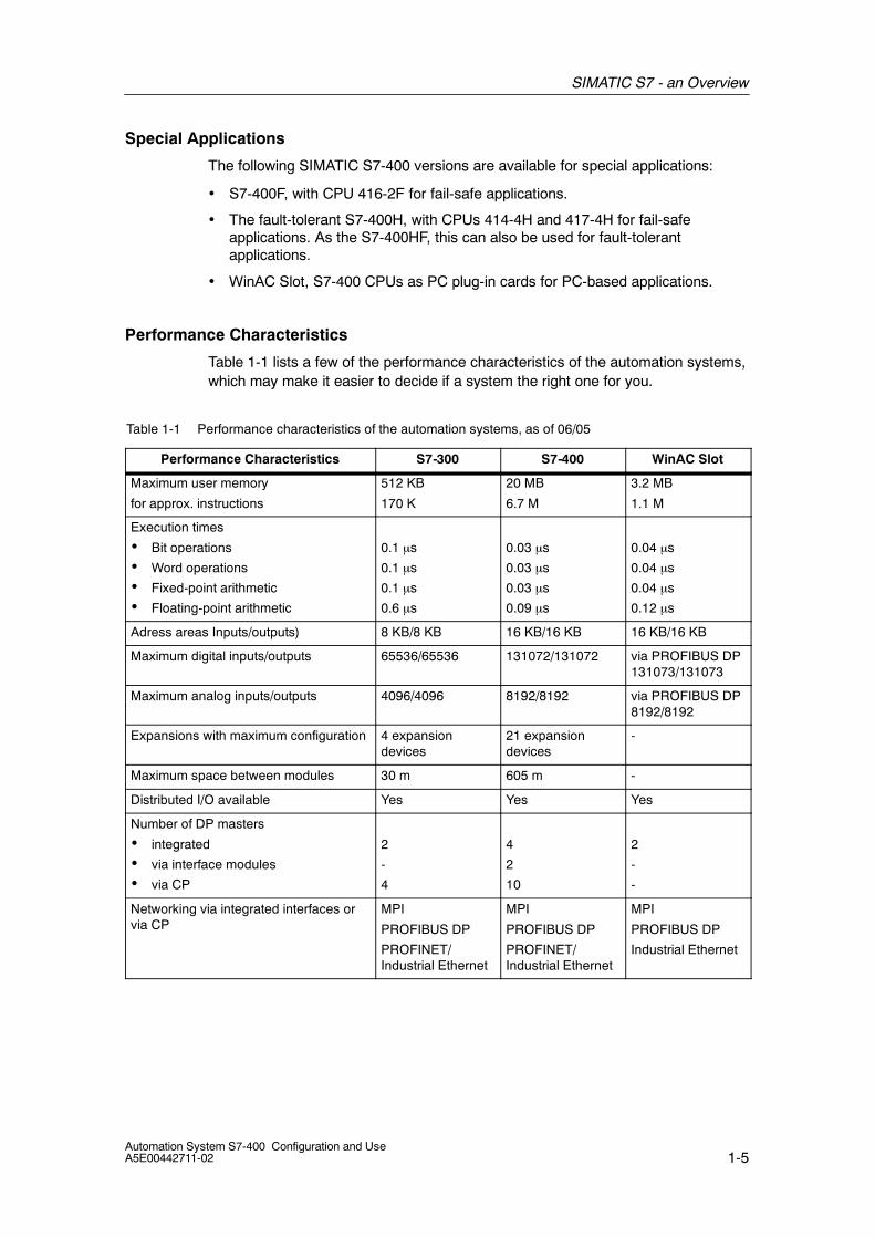
Performance Characteristics
Table 1-1 lists a few of the performance characteristics of the automation systems,which may make it easier to decide if a system the right one for you.
Table 1-1 Performance characteristics of the automation systems, as of 06/05
Performance Characteristics S7-300 S7-400 WinAC Slot
Maximum user memory
for approx. instructions
512 KB
170 K
20 MB
6.7 M
3.2 MB
1.1 M
Execution times
• Bit operations
• Word operations
• Fixed-point arithmetic
• Floating-point arithmetic
0.1 µs
0.1 µs
0.1 µs
0.6 µs
0.03 µs
0.03 µs
0.03 µs
0.09 µs
0.04 µs
0.04 µs
0.04 µs
0.12 µs
Adress areas Inputs/outputs) 8 KB/8 KB 16 KB/16 KB 16 KB/16 KB
Maximum digital inputs/outputs 65536/65536 131072/131072 via PROFIBUS DP131073/131073
Maximum analog inputs/outputs 4096/4096 8192/8192 via PROFIBUS DP8192/8192
Expansions with maximum configuration 4 expansiondevices
21 expansiondevices
-
Maximum space between modules 30 m 605 m -
Distributed I/O available Yes Yes Yes
Number of DP masters
• integrated
• via interface modules
• via CP
2
-
4
4
2
10
2
-
-
Networking via integrated interfaces orvia CP
MPI
PROFIBUS DP
PROFINET/Industrial Ethernet
MPI
PROFIBUS DP
PROFINET/Industrial Ethernet
MPI
PROFIBUS DP
Industrial Ethernet

SIMATIC S7 - an Overview
1-6Automation System S7-400 Configuration and Use
A5E00442711-02
1.3 An Overview of S7-400 Components
Introduction
In order for the S7-400 to adapt to and fulfill each and every task, a tiered range ofcomponents varying in performance is available for a wide range of functions.
All of these components are matched to one another and can therefore be easilyintegrated to form a complete system.
Figure 1-1 shows a configuration of an S7-400 with several modules in a rack.
Figure 1-1 An S7-400 configuration
CPU
The CPU is responsible for the control and regulation of the processes. CPUs withvarying performance capability are offered for the S7-400. They differ from oneanother in the size of the user memory, the processing speed and number ofinterfaces they offer.

SIMATIC S7 - an Overview
1-7Automation System S7-400 Configuration and UseA5E00442711-02
Racks
The various modules of the S7-400 automation system are inserted and fastenedin a rack. The backplane bus of the rack is divided into two different bus systems:
• I/O bus: The P bus is a parallel backplane bus, which is designed for fastexchange of input and output signals.
• C bus: The C bus is a serial backplane bus, which is designed for the exchangeof larges amounts of data.
A total of 22 racks can be connected with one another via interface modules.
Power Supply
The power supply module provides the required operating voltage via thebackplane bus of the rack. The available supply voltage and required drive powerof the modules determines the selection of the correct power supply. Powersupplies are also available with diagnostics and can be configured redundantly ifrequired.
Signal Modules
A wide variety of digital and analog input and output modules (signal modules, SM)are available for adapting to a wide-range of actuators and sensor signals. Signalmodules are also available with alarm processing and diagnostics.
Function Modules
Function modules (FM) are specialists for integrating the following plant functions:
• Counting and measuring
• Positioning
• Controlling
• Cam controlling
Interface Modules
Interface modules (IM) are needed to interconnect racks in multi-tierconfigurations.
Communication Modules
Communication tasks can be realized directly via the interfaces of the CPU orusing special communication modules (communication processors, CP) to connectto the following networks or couplers:
• PROFIBUS DP
• PROFINET
• Industrial Ethernet (including IT functionality)
• Point-to-point connections
SIMATIC S7 - an Overview
1-8Automation System S7-400 Configuration and Use
A5E00442711-02
1.4 S7-400 - Configuration Variants
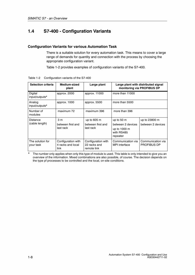
Configuration Variants for various Automation Task
There is a suitable solution for every automation task. This means to cover a largerange of demands for quantity and connection with the process by choosing theappropriate configuration variant.
Table 1-2 provides examples of configuration variants of the S7-400.
Table 1-2 Configuration variants of the S7-400
Selection criteria Medium-sizedplant
Large plant Large plant with distributed signalmonitoring via PROFIBUS DP
Digitalinput/outputs*
approx. 2000 approx. 11000 more than 11000
Analoginput/outputs*
approx. 1000 approx. 5500 more than 5500
Number ofmodules
maximum 72 maximum 396 more than 396
Distance(cable length)
3 m
between first andlast rack
up to 605 m
between first andlast rack
up to 50 m
between 2 devices
up to 1000 mwith RS485repeater
up to 23800 m
between 2 devices
The solution foryour task
Configuration with4 racks and locallink
Configuration with22 racks andremote link
Communication viaMPI interface
Communication viaPROFIBUS DP
* The number only applies when only this type of module is used. This table is only intended to give you anoverview of the information. Mixed combinations are also possible, of course. The decision depends onthe type pf processes to be controlled and the local, on-site conditions.
2-1Automation System S7-400 Configuration and UseA5E00442711-02
CPUs of the S7-400
Overview
The following information is contained in this chapter:
• A few of the exceptional features of the S7-400 CPUs.
• A comparison of the areas of application and performance characteristics ofthese CPUs.
2

CPUs of the S7-400
2-2Automation System S7-400 Configuration and Use
A5E00442711-02
2.1 CPUs of the S7-400 - System-wide Compatibility
Introduction
There is a tiered range of CPUs within the S7-400. You can therefore select themost suitable and economic solution for your application.
The following will describe a few of the features that the S7-400 CPUs have incommon and exemplify the system-wide compatibility. Figure 2-1 shows adouble-width CPU with its interfaces, operator controls and display components.
Operating mode switch
Slot for memory cardwith memory card
Incoming external buffer voltage
Module slot withinterface module 1
Module slot withinterface module2
MPI/Profibus DP interface
Profibus DP interface
LED indicators INTF, EXTF,BUS1F, FRCE, RUN, STOP,
BUS2F, IFM1F, IFM2F
Label with module name, productversion, abbreviated order number and
firmware version
Figure 2-1 Arrangement of the S7-400 CPUs’ operator controls and display components
Operating Mode Switch of the S7-400
You can use the operating mode switch to set the CPU in the operating modesRUN or STOP or to bootstrap the CPU. The operating mode switch is a toggleswitch.
You can also change the operating mode in STEP 7.
CPUs of the S7-400
2-3Automation System S7-400 Configuration and UseA5E00442711-02
Uniform Displays
The following applies to the status and error displays of the S7-400:
• Identical errors are always displayed in the same way.
• Identical displays are always located at the same location on the front of themodule.
• The meaning of flash frequencies is always the same.
To summarize, once you understand the display principle of one module, you caninterpret the displays of all other modules.
MPI/DP Interface
All CPUs feature an integrated interface with multi-point capability (MPI).
The MPI interfacce is used for the following tasks:
• Programming and parameter assignment
• Operator control and monitoring
• Configuring simple network structures between CPUsS7-300 and S7-400 CPUs exchange data via the MPI interface using a varietyof communication functions.
Using this interface as a DP interface and the CPU as a DP master, you canoperate up to 32 DP slaves.
Profibus DP Interface
Except for the CPU 412-1, all CPUs feature at least one other interface forconnecting to Profibus DP in addition to the MPI/DP interface.
The Profibus DP interfacce is used for the following tasks:
• The CPU acts as the DP master to accees all stations on the Profibus DP.
• The CPU itself is a DP slave on a DP interface.
You can equip CPUs 41x-3 and 41x-4 with interface modules to provide additionalDP interfaces.
I/O Expansion
Any CPU can be used in the S7-400 product range.
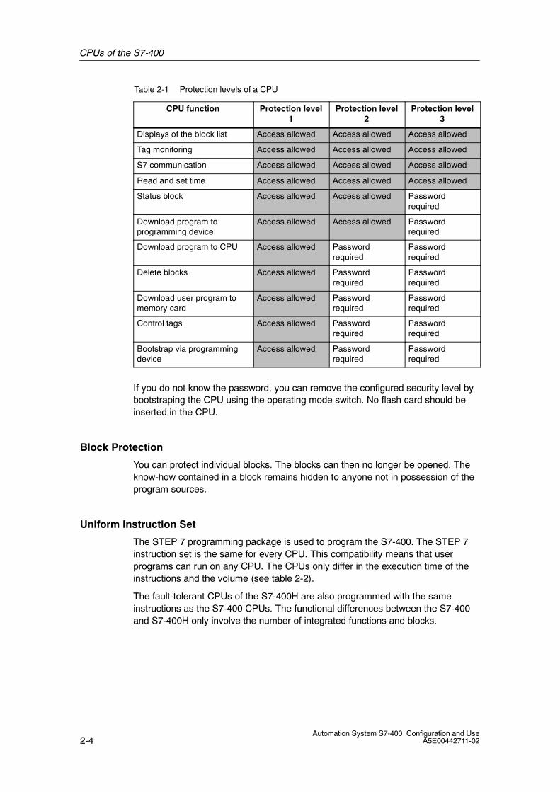
Password Protection
You can assign three levels of access rights for CPUs from the programmingdevice in STEP 7. To assign a protection level, you specify a password, which hasto be entered before unrestricted access to a ”protected” CPU is allowed.
Table 2-1 shows an example of a selection of CPU functions and how they areassigned to the various levels of protection.
CPUs of the S7-400
2-4Automation System S7-400 Configuration and Use
A5E00442711-02
Table 2-1 Protection levels of a CPU
CPU function Protection level1
Protection level2
Protection level3
Displays of the block list Access allowed Access allowed Access allowed
Tag monitoring Access allowed Access allowed Access allowed
S7 communication Access allowed Access allowed Access allowed
Read and set time Access allowed Access allowed Access allowed
Status block Access allowed Access allowed Passwordrequired
Download program toprogramming device
Access allowed Access allowed Passwordrequired
Download program to CPU Access allowed Passwordrequired
Passwordrequired
Delete blocks Access allowed Passwordrequired
Passwordrequired
Download user program tomemory card
Access allowed Passwordrequired
Passwordrequired
Control tags Access allowed Passwordrequired
Passwordrequired
Bootstrap via programmingdevice
Access allowed Passwordrequired
Passwordrequired
If you do not know the password, you can remove the configured security level bybootstraping the CPU using the operating mode switch. No flash card should beinserted in the CPU.
Block Protection
You can protect individual blocks. The blocks can then no longer be opened. Theknow-how contained in a block remains hidden to anyone not in possession of theprogram sources.
Uniform Instruction Set
The STEP 7 programming package is used to program the S7-400. The STEP 7instruction set is the same for every CPU. This compatibility means that userprograms can run on any CPU. The CPUs only differ in the execution time of theinstructions and the volume (see table 2-2).
The fault-tolerant CPUs of the S7-400H are also programmed with the sameinstructions as the S7-400 CPUs. The functional differences between the S7-400and S7-400H only involve the number of integrated functions and blocks.
CPUs of the S7-400
2-5Automation System S7-400 Configuration and UseA5E00442711-02
Integrated Functions
The operating system of each CPU features the following integrated functions,which simplify the user program considerably:
• Operating control and monitoring functions
• Functions for communication
• Functions for diagnostics
• Functions for transmission of data records
• Functions for program control
• Functions for interrupt handling
• Functions for generating messages
The integration of these functions in the operating system means that there is noneed for tedious programming and the cycle time load of the CPU is reduced.
Diagnostics Buffer
Each CPU features a diagnostics buffer, in which error and diagnostic messagesare entered and stored.
Messages are entered into the diagnostics buffer either by the CPU or othermodules. User-defined diagnostic messages can also be entered by the userprogram.
These messages can be read by the programming device at any time. The dateand time of the entry is also included. Messages can also be sent to operatorcontrol and monitoring stations. The diagnostics buffer entries cannot bemanipulated. The most recent 120 entries are retained even after ”bootstrapping”.
CPUs of the S7-400
2-6Automation System S7-400 Configuration and Use
A5E00442711-02
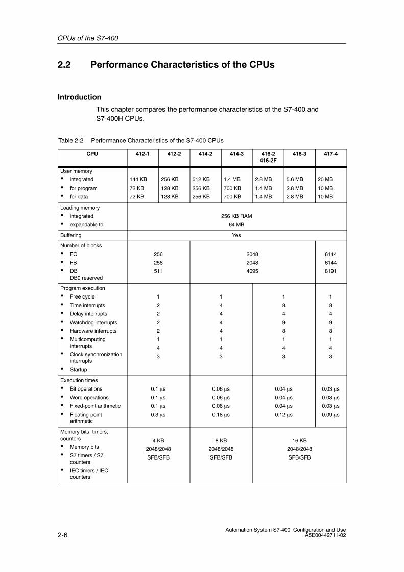
2.2 Performance Characteristics of the CPUs
Introduction
This chapter compares the performance characteristics of the S7-400 andS7-400H CPUs.
Table 2-2 Performance Characteristics of the S7-400 CPUs
CPU 412-1 412-2 414-2 414-3 416-2416-2F
416-3 417-4
User memory
• integrated
• for program
• for data
144 KB
72 KB
72 KB
256 KB
128 KB
128 KB
512 KB
256 KB
256 KB
1.4 MB
700 KB
700 KB
2.8 MB
1.4 MB
1.4 MB
5.6 MB
2.8 MB
2.8 MB
20 MB
10 MB
10 MB
Loading memory
• integrated
• expandable to
256 KB RAM
64 MB
Buffering Yes
Number of blocks
• FC
• FB
• DBDB0 reserved
256
256
511
2048
2048
4095
6144
6144
8191
Program execution
• Free cycle
• Time interrupts
• Delay interrupts
• Watchdog interrupts
• Hardware interrupts
• Multicomputinginterrupts
• Clock synchronizationinterrupts
• Startup
1
2
2
2
2
1
4
3
1
4
4
4
4
1
4
3
1
8
4
9
8
1
4
3
1
8
4
9
8
1
4
3
Execution times
• Bit operations
• Word operations
• Fixed-point arithmetic
• Floating-pointarithmetic
0.1 µs
0.1 µs
0.1 µs
0.3 µs
0.06 µs
0.06 µs
0.06 µs
0.18 µs
0.04 µs
0.04 µs
0.04 µs
0.12 µs
0.03 µs
0.03 µs
0.03 µs
0.09 µs
Memory bits, timers,counters
• Memory bits
• S7 timers / S7counters
• IEC timers / IECcounters
4 KB
2048/2048
SFB/SFB
8 KB
2048/2048
SFB/SFB
16 KB
2048/2048
SFB/SFB
CPUs of the S7-400
2-7Automation System S7-400 Configuration and UseA5E00442711-02
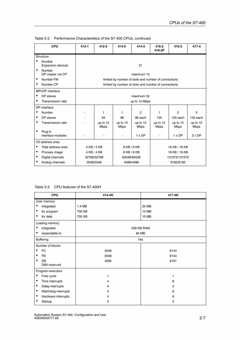
Table 2-2 Performance Characteristics of the S7-400 CPUs, continued
CPU 417-4416-3416-2416-2F
414-3414-2412-2412-1
Structure
• NumberExpansion devices
• NumberDP master via CP
• Number FM
• Number CP
21
maximum 10
limited by number of slots and number of connections
limited by number of slots and number of connections
MPI/DP interface
• DP slaves
• Transmission rate
maximum 32
up to 12 Mbps
DP interface
• Number
• DP slaves
• Transmission rate
• Plug-ininterface modules
-
-
-
-
1
64
up to 12Mbps
-
1
96
up to 12Mbps
-
2
96 each
up to 12Mbps
1 x DP
1
125
up to 12Mbps
-
2
125 each
up to 12Mbps
1 x DP
3
125 each
up to 12Mbps
2 x DP
I/O address area
• Total address area
• Process image
• Digital channels
• Analog channels
4 KB / 4 KB
4 KB / 4 KB
32768/32768
2048/2048
8 KB / 8 KB
8 KB / 8 KB
65536/65536
4096/4096
16 KB / 16 KB
16 KB / 16 KB
131072/131072
8192/8192
Table 2-3 CPU features of the S7-400H
CPU 414-4H 417-4H
User memory
• integrated
• for program
• for data
1.4 MB
700 KB
700 KB
20 MB
10 MB
10 MB
Loading memory
• integrated
• expandable to
256 KB RAM
64 MB
Buffering Yes
Number of blocks
• FC
• FB
• DBDB0 reserved
2048
2048
4095
6144
6144
8191
Program execution
• Free cycle
• Time interrupts
• Delay interrupts
• Watchdog interrupts
• Hardware interrupts
• Startup
1
4
4
4
4
2
1
8
4
9
8
2

CPUs of the S7-400
2-8Automation System S7-400 Configuration and Use
A5E00442711-02
Table 2-3 CPU features of the S7-400H, continued
CPU 417-4H414-4H
Execution times
• Bit operations
• Word operations
• Fixed-point arithmetic
• Floating-pointarithmetic
0.06 µs
0.06 µs
0.06 µs
0.18 µs
0.03 µs
0.03 µs
0.03 µs
0.09 µs
Memory bits, timers,counters
• Memory bits
• S7 timers / S7counters
• IEC timers / IECcounters
8 KB
2048/2048
SFB/SFB
16 KB
2048/2048
SFB/SFB
Structure
• NumberExpansion devices
• NumberDP master via CP
• Number FM
• Number CP 441
21
maximum 10
limited by number of slots and number of connections
limited by number of connections, maximum 30
MPI/DP interface
• DP slaves
• Transmission rate
maximum 32
up to 12 Mbps
DP interface
• Number
• DP slaves
• Transmission rate
1
96 each
up to 12 Mbps
1
125 each
up to 12 Mbps
I/O address area
• Total address area
• Process image
• Digital channels
• Analog channels
8 KB / 8 KB
8 KB / 8 KB
65536/65536
4096/4096
16 KB / 16 KB
16 KB / 16 KB
131072/131072
8192/8192
CPUs of the S7-400
2-9Automation System S7-400 Configuration and UseA5E00442711-02
2.3 Memory Concept
Introduction
The CPUs of the S7-400 have the following types of memory:
• Loading memory for project data, for example, blocks, configuration andparameter assignment data including symbols and comments.
• User memory for the runtime-relevant blocks (code blocks and data blocks) andthe system memory.
Loading Memory
The loading memory consists of a plug-in memory card (RAM or FLASH EPROM).An integrated RAM is provided for test purposes or for reloading/correcting blockswhen a FLASH EPROM memory card is used.
Additional information is stored in the loading memory along with the project data.This might include format identifications, symbols and comments, to enable fulldecompiling of the user program with any programming device. The loadingmemory also stores the parameter blocks for other modules used in theautomation system.
User Memory
The user memory (integrated RAM) is used to hold the parts of the user programthat are relevant for executing the program. The program is executed exclusively inthe area of the user and system memory.
System Memory
The system memory contains the memory elements that each CPU makesavailable to the user program, such as the process image of the inputs and outputsand local data.
Buffering
The CPUs of the SIMATIC S7-400 are buffered by the power supply module,enabling them to retain their entire memory contents if a power failure occurs. Thepower supply modules feature either one or two batteries. They can also beoperated with a back-up battery, however.
The CPUs can also be backed up by an external power source.
Retention of Timers, Counters, Memory Bits and Data Blocks
Timers, counters, memory bits and data blocks can retain their old values evenafter reboot. All you have to do for this is to define these operands as non-volatileusing STEP 7.

CPUs of the S7-400
2-10Automation System S7-400 Configuration and Use
A5E00442711-02
2.4 Multicomputing
Introduction
Multicomputing mode is the simultaneous operation of several (maximum of four)CPUs in a single central controller of the S7-400.
The CPUs involved automatically change their modes synchronously. In otherwords, they start up together and change to STOP mode together. The userprogram runs on each CPU irrespective of the user programs in the other CPUs.This makes it possible to execute controller tasks in parallel.
Multicomputing mode is not available with the CPUs of the S7-400H.
When do you use multicomputing?
It is advantageous to use multicomputing in the following cases:
• If your user program is too large for a single CPU and memory is limited, youcan distribute your program over several CPUs.
• If a certain part of your system is supposed to be processed quickly, separatethe relevant program section from the overall program and have it processed bya dedicated, “fast” CPU.
• If your system consists of several different parts that can be easily separatedfrom one another and can therefore be controlled relatively independently, letCPU1 process system part 1, CPU 2 system part 2 and so on.
Assigning Modules to the CPUs
In multicomputing mode, the individual CPUs can each access the modules thatwere allocated to them during configuration with STEP 7. The address area of amodule is always assigned ”exclusively” to one CPU.
Each interrupt-capable module is therefore assigned to a CPU. Interruptsoriginating from such a module cannot be received by the other CPUs.
I/O Volume
The typical I/O volume of an automation system in multicomputing modecorresponds to the volume of the CPU with the most resources
CPUs of the S7-400
2-11Automation System S7-400 Configuration and UseA5E00442711-02
2.5 Configuration in Run
Introduction
The ability to modify the system during operation using CiR (Configuration in RUN)allows you to make certain changes to the configuration in the RUN mode.Processing is halted for a brief period in order to accomplish this. During this time,the process inputs retain their most recent value.
Area of Application
You can modify the system during operation using CiR in system segments withdistributed I/O. This can be done with all standard CPUs of the S7-400 and for thefault-tolerant S7-400H-CPUs running in single mode.
Permitted Configuration Changes in Run Overview
The following modifications can be made to the system in the Run mode:
• Modules can be added to the modular DP slave ET 200M, if it has not beenconnected as a DPV0 slave (using a GSD file).
• ET 200M modules can be reconfigured, for example, another interrupt limit canbe selected or previously unused channels can be used.
• A previously unused channel in a module or a module for the modular slavesET 200M, ET 200S, ET 200iS can be used.
• DP slaves can be added to an existing DP master system.
• PA slaves (field devices) can be added to an existing PA master system.
• DP/PA couplers can be added downstream from an IM157.
• PA links (including PA master systems) can be added to an existing DP mastersystem.
• Modules can be assigned to a process image partition.
• Existing modules in ET 200M stations (standard modules and fail-safe signalmodules in standard mode) can be reconfigured.
• Changes can be reversed: added modules, DP slaves and PA slaves (fielddevices) can be removed.
Configuration Changes in Run with Fault-tolerant CPUs
In addition to the system changes described above, you can make the followingconfiguration changes in Run when using fault-tolerant automation systems:
• Upgrade to a newer product version
• Switch the master with only one available redundancy coupling

CPUs of the S7-400
2-12Automation System S7-400 Configuration and Use
A5E00442711-02
2.6 Clock Synchronicity
Introduction
Clock synchronicity is the synchronous coupling of the signal detection and signaloutput via the distributed I/O and the program execution to the PROFIBUS clockpulse.
Clock synchronicity is not available with the CPUs of the S7-400H.
Advantages
Clock synchronicity offers the following advantages:
• The input data are always read in the same intervals and the output data arealways generated in the same intervals.
• All input and output data are transmitted in a consistent manner. All the data inthe process image belong together in both a logical and a chronological sense.
• The user program, the acquisition of the input data and the generation of outputdata are synchronized. The process reaction times are therefore always thesame.
CPUs of the S7-400
2-13Automation System S7-400 Configuration and UseA5E00442711-02
2.7 The CPUs S7-400H for Fault-tolerant Controllers
Introduction
You use redundant automation systems to increase availability and avoidproduction losses.
The higher the costs of a production standstill, the more worthwhile it is to use afault-tolerant system. The investment costs associated with a fault-tolerant systemis quickly offset by the savings resulting from decreased production downtime.
The S7-400H automation system meets the high requirements for availability,intelligence and distributed operation that are required of modern automationsystems. It also features all the functions for acquiring and preparing process dataand for controlling, regulating and monitoring equipment and plants.
Tiered Availability with Redundant Components
The S7-400H is designed with redundancy so that it remains available in everysituation.
This includes the CPU, the power supply and the hardware for interconnecting thetwo CPUs.
The two CPUs form the core of the S7-400H. You set the rack numbers of theCPUs with a switch at the back. The two subsystems can be identified by theirrespective rack number.
You yourself can decide which components to implement redundantly to increasetheir availability based on the process you are automating.
Synchronization Modules
Synchronization modules are used for the communication between two redundantS7-400H CPUs. They are integrated into the CPUs and interconnected via fiberoptic cables. You need two synchronization modules for each CPU.
There are two types of synchronization modules, one with a cable length of 10 mbetween the CPUs and another with a cable length of up to 10 km.
You can replace a synchronization module when it is energized. This supports therepair scenario for H systems and thus can overcome the failure of the redundantconnection without having to bring the plant to a stop.
CPUs of the S7-400
2-14Automation System S7-400 Configuration and Use
A5E00442711-02
Linking and Synchronizing
There are two methods for linking and synchronizing:
• In a “normal” link and synchronization procedure, the fault-tolerant systemshould change from single mode to redundant system mode. The two CPUsthen process the same program synchronously.
• In the case of a link and synchronization with master/standby switch-over, thesecond CPU with modified components may take over process control. Eitherthe hardware configuration or the memory configuration can be modified.
In order to return to redundant system mode, a “normal“ link andsynchronization must be subsequently performed.
Programming an H System
When you configure and program a fault-tolerant automation system with H CPUs,certain differences to the standard S7-400 CPUs become apparent. On the onehand, compared to a standard S7-400 CPU, a fault-tolerant CPU has additionalfunctions, while on the other hand an H CPU does not support certain otherfunctions. This has to be taken in account particularly if you wish to run a programthat was created for a standard S7-400 CPU on an H CPU.
Fault-tolerant Connections
The controller and the I/O can be redundantly configured for a fault-tolerantcontroller. With growing demands on the availability of an overall system, it isnecessary to increase the fault tolerance of the communication. To do this,configure redundant communication and use fault-tolerant S7 connections.
Unlike the S7 connection, a fault-tolerant S7 connection consists of at least twolower-level partial connections. From the point of view of the user program, theconfiguration and the connection diagnostics, the fault-tolerant S7 connection withits subordinate partial connections is represented by exactly one ID (like astandard S7 connection). Depending on the configuration, it can consist of up tofour partial connections, of which two are always established (active). Thismaintains communications in the event of an error. The number of partialconnections depends on possible alternative paths and is determinedautomatically.
If the active partial connection fails, a previously established second partialconnection assumes responsibility for communications.
CPUs of the S7-400
2-15Automation System S7-400 Configuration and UseA5E00442711-02
Self-test
Disruptions or errors have to be detected, located and reported as quickly aspossible. Consequently, wide-ranging self-test functions have been implemented inthe S7-400H that run automatically and entirely in the background.
The following components and functions are tested:
• Interconnection of the central controllers
• Internal memory of the CPU
• I/O bus
If the self-test detects an error, the fault-tolerant system tries to eliminate it or tosuppress its effects.
Single-channel, One-way I/O
In the single-channel, one-way configuration, there are single input/output modules(single-channel). The input/output modules are located in just one of thesubsystems and are only addressed by that subsystem.
The single-channel, one-way I/O configuration is recommended for individualinput/output channels for which normal availability of the I/O is sufficient.
Single-channel, Switched I/O
In the single-channel, switched configuration, there are single input/output modules(single-channel). In redundant mode, they can be addressed by both subsystems.The single-channel, switched I/O configuration is recommended for devices thattolerate the failure of individual modules.
The single-channel, switched I/O configuration is possible with the ET 200M undET 200 iSP distributed I/O devices or redundant standard slaves, for example.
PROFIBUS PA can be connected to a redundant system using DP/PA Link. Asingle-channel DP master system can be connected to a redundant system using aY-coupler.
Redundant I/O
I/O modules are considered redundant when there are two of each and they areconfigured and operated as redundant pairs. The use of redundant I/O providesthe highest degree of availability since it means that failure of a CPU failure andfailure of a signal module are both tolerated.
The implementation of redundant I/O is supported by the software blocksintegrated in STEP 7.
Redundant Input Modules
With redundant input modules, the measured values or input signals are read byboth modules and the results are compared. When the results are the same orwithin a configured tolerance window, they are further processed.
CPUs of the S7-400
2-16Automation System S7-400 Configuration and Use
A5E00442711-02
Redundant Digital Output Modules
The fault-tolerant control of an actuator can be achieved by connecting two outputsof two digital output modules in parallel
Redundant Analog Output Modules
You can redundantly operate analog output modules with power outputs.
The value to be output is halved and each module outputs one half of the value. Ifone of the modules fails, this is detected and the remaining module outputs the fullvalue. This reduces any current surge to the output module when an error occurs.
Single Operation
You can also use an H CPU in a standard SIMATIC-400 station.
This allows you to use the following applications that cannot be used with thestandard CPUs from the S7-400 range:
• Use of fault-tolerant connections
• Configuration of the S7-400F/FH fail-safe automation system

CPUs of the S7-400
2-17Automation System S7-400 Configuration and UseA5E00442711-02
System-wide Compatibility
The S7-400H automation system and all other SIMATIC components such as theSIMATIC PCS7 control system are perfectly matched. Full system compatibility,from the control console to the sensors and actuators, guarantees maximumsystem performance.
Control console
Automationsystems
S7-400S7-400H
SystemS7-300
ET 200M
ET 200B ET 200L ET 200pro
OS single station
Log printer
Server Server
S7-400 with
H-CPU
Client Client
Engineering
system
DP/PA bus coupler
LAN, optical ring
PROFIBUS DP (redundant)
Distributed
I/OSensors/actuators
ET 200MET 200pro
DP/PA bus coupler
Distributed
I/OSensors/actuators
S7-400
ET 200L
ET 200M DP/PA bus coupler
PROFIBUS DP
Distributed
I/O
Sensors/actuators
IE/PB Link
PN IO
PROFIBUS DP
PN/IO
Figure 2-2 Compatible automation solutions with SIMATIC
CPUs of the S7-400
2-18Automation System S7-400 Configuration and Use
A5E00442711-02
2.8 CPU 416F for Fail-safe Controlling (Distributed Safety)
Introduction
Fail-safe, S7 Distributed Safety is used in the area of machine and personnelprotection (for example, for emergency stop devices for machining and processingequipment) and in the process industry (for example, for implementation ofprotection functions for small instrumentation and control devices and smallburners).
S7-400F Automation System
An S7-400F automation system is built with a CPU 416F. The CPU 416F is basedon the corresponding standard CPU 416. Its hardware and operating system isenhanced by several protection mechanisms that allow the CPU 416F to executesafety programs.
Safety Requirements
F-systems S7 Distributed Safety can fulfill the following safety requirements:
• Requirement class AK1 to AK6 in accordance with DIN V 19250/DIN V VDE0801
• Safety class (Safety Integrity Level) SIL1 to SIL3 in accordance with IEC 61508
• Category 2 to 4 in accordance with EN 954-1
Principle of Safety Functions S7 Distributed Safety
Fail-safe behavior is achieved by means of safety functions primarily in thesoftware. Safety functions are executed by the S7 F Distributed Safetyprogrammable controller in order to return the system to a safe state, or keep it ina safe state when a hazardous event occurs. The safety functions are primarilyincorporated in the following components:
• In the safety-related user program on the central processing unit
• In the fail-safe input/output modules
The fail--safe I/O ensure safe processing of field information (emergency OFFbuttons, light barriers, motor control). They contain all of the required hardware andsoftware components for safe processing, in accordance with the required safetyclass. The user only programs the user safety function. The safety function for theprocess can be provided through a user safety function or a fault reaction function.In the event of a fault, if the F-system can no longer execute its actual user safetyfunction, it executes the fault reaction function; for example, the associated outputsare deactivated and the F-CPU switches to STOP mode, if necessary.
CPUs of the S7-400
2-19Automation System S7-400 Configuration and UseA5E00442711-02
Hardware Components
The hardware components of an S7 Distributed Safety include the following:
• F-capable CPU, e. g. CPU 416-2F
• Fail-safe I/O
In addition, the F-system can be expanded with standard components of theS7-400.
Software Components
The software components of an S7 Distributed Safety include the following:
• Optional package on the programming device/ES for configuring andprogramming the F-system
• Safety program in the F-CPU
Optional Package S7 Distributed Safety
S7 Distributed Safety is the configuration and programming software for theS7 Distributed Safety fail-safe system. With S7 Distributed Safety, you receive thefollowing:
• Support for configuring the F-I/O in STEP 7 using HW Config
• Support for creating the safety program and integrating error detection functionsinto the safety program
• F-library containing fail-safe application blocks that you can use in your safetyprogram.
Moreover, S7 Distributed Safety offers functions for comparing safety programsand for assisting you with the system acceptance test.

CPUs of the S7-400
2-20Automation System S7-400 Configuration and Use
A5E00442711-02
2.9 The CPUs 41xH for Fail-safe and Fault-tolerantControllers (F/FH Systems)
Introduction
Fail-safe S7 F/FH systems are used in process engineering and instrumentationand control systems in which a safe state can be attained by switching off thefail-safe outputs.
S7-400F Automation System
An S7-400F system consists of a fail-safe capable CPU such as CPU 417-4 H thatcan run a fail-safe user program
S7-400FH Automation System
An S7-400FH system consists of a fault-tolerant S7 400H system (master andstandby) running a fail-safe user program
An S7-400FH automation system is built with S7-400H CPUs. You increase theavailability by implementing a redundant power supply, CPU, communication andI/O.
Safety Requirements
Fail-safe S7 F/FH Systems can satisfy the following safety requirements:
• Requirement class AK1 to AK6 in accordance with DIN V 19250/DIN V VDE0801
• Safety class (Safety Integrity Level) SIL1 to SIL3 in accordance with IEC 61508
• Category 2 to Category 4 in accordance with EN 954--1
Principle of Safety Functions
Functional safety is implemented principally through safety functions in thesoftware. Safety functions are executed by the fail-safe S7 F/FH system to placeor maintain the system in a safe state in case of a dangerous occurrence.Thesafety function for the process can be provided through a user safety function or afault reaction function. In the event of a fault, if the F-system can no longer executeits actual user safety function, it executes the fault reaction function. For example,the associated outputs are deactivated, and the safety program or parts of thesafety programm are disabled, if necessary.

CPUs of the S7-400
2-21Automation System S7-400 Configuration and UseA5E00442711-02
Hardware Components
An F-System consists of hardware components that fulfill certain safetyrequirements, such as:
• A CPU, such as the CPU 417-4H, with an F-copy license
• F-I/Os
You can also expand the F--System with standard components.
Software Components
The software components of a S7 F-System include the following:
• S7 F Systems (Programming)
• S7 F Configuration Pack (Configuration of the F-I/Os)
• The fail-safe user program (F user program) on the CPU
Creating a Fail-safe User Program
You create the fail-safe user program in CFC using fail-safe blocks from the”Fail-safe Blocks” library. For the connection to the F-I/Os, you use F channel andmodule driver blocks, to which you have to assign parameters. Some of theparameters are assigned automatically as a result of the hardware configuration ofthe F-I/Os.
When the executable fail-safe user program is generated, safety tests are carriedout automatically and additional fault detection functions incorporated.

CPUs of the S7-400
2-22Automation System S7-400 Configuration and Use
A5E00442711-02
3-1Automation System S7-400 Configuration and UseA5E00442711-02
Signal Modules of the S7-400
Overview
The following information is contained in this chapter:
• Configuration of the S7-400 signal modules using STEP 7 on the programmingdevice.
• Addressing the S7-400 signal modules.
• An overview of the S7-400 signal modules with their most importantperformance characteristics.
3
Signal Modules of the S7-400
3-2Automation System S7-400 Configuration and Use
A5E00442711-02
3.1 Signal Modules
Introduction
There are numerous signal modules for the S7-400 automation system. You cantherefore select the most suitable and economic solution for your application.
Digital and Analog Modules
Digital and analog modules are collectively referred to as ”signal modules” (SM).The ’SM’ abbreviation that is printed on these modules stands for the internationaldesignation, ”signal module”.
Advantages
The modules of the S7-400 offer you the following advantages:
• The modules of the S7-400 are compact and feature high channel density.
• The modules of the S7-400 require little space and are extremely easy tomount.
• The modules of the S7-400 are designed with uniform connection and displayfeatures.
• All connections are located behind a hinged cover on the front of the modules.
• All modules are configured using the programming software, STEP 7.
• The modules can be hot pulled and plugged.
Signal Modules of the S7-400
3-3Automation System S7-400 Configuration and UseA5E00442711-02
3.2 Assigning Parameters to Signal Modules
Introduction
In this chapter you will learn more about the options available for configuring andassigning parameters to the modules of SIMATIC S7.
Parameter Assignment with Software
STEP 7 enables you to easily enter all parameters in guided dialogs. For example,the measurement range for analog modules is set using STEP 7.
The parameters are transferred to the CPU with STEP 7. The CPU then distributesthe parameters to the modules at startup.
Advantages
Parameter assignment using STEP 7 offers you the following advantages:
• The modules are easily configured, you can easily change and convenientlydocument the parameter assignments.
• It is impossible to make incorrect settings when exchanging modules.
• Since the parameters and addresses are stored in STEP 7, you can alwayscopy, document and easily change these settings for a whole series of similarcontrollers.
Signal Modules of the S7-400
3-4Automation System S7-400 Configuration and Use
A5E00442711-02
3.3 Addressing Signal Modules
Introduction
The address ranges of the S7-400 are adapted to the requirements foreasy-to-operate, high-performance controllers. In this chapter, you will learn whichaddress areas are used for SIMATIC S7 and how the addresses are assigned.
Address Ranges
The following address ranges are used for working with SIMATIC S7:
• I/O area
Inputs/outputs of digital and analog modules, function modules
• System data area
Parameter sets, diagnostic data
Access to the I/O Area of Digital Modules
The process image is accessed indirectly. The information from the inputs and tothe outputs is stored in the process image. Direct access is also possible here.
Access to the I/O Area of Analog Modules
The inputs and outputs are access directly. In other words, currently queued valuesat the inputs are processed in the program and the results are immediatelyforwarded to the outputs. Indirect access is also possible via the process image.
Access to System Data
System calls are integrated in the CPU. The system calls allow access to systemdata for parameter sets and diagnostic data for each slot and are performed in theuser program.
Addressing with STEP 7
You can use STEP 7 to set the addresses for communicating with the modules. Nohardware settings using jumpers or switches are needed.
Signal Modules of the S7-400
3-5Automation System S7-400 Configuration and UseA5E00442711-02
3.4 Overview of the Performance Characteristics of theSignal Modules
Introduction
Varying signal types (analog and digital) and signal levels (voltage levels) of theactuators and sensors required different signal modules to process the signals inthe CPU.
The S7-400 offers a wide range of signal modules to handle any type of controllersignals.
Process Interrupt
The signals of the modules are read by the CPU in cycles and processed in theuser program.
Some applications, however, require fast response to certain signal transitions inthe I/O. This task demands signal modules that are capable of triggering processinterrupts. The process interrupt stops the processing and user program and callsup a configured interrupt OB.
Diagnostics
When an fault occurs, a wire-break at the module, for example, the cyclic programis stopped, a diagnostic interrupt triggered and a specific error program started. Adiagnostic message is also entered in the diagnostics buffer of the CPU.

Signal Modules of the S7-400
3-6Automation System S7-400 Configuration and Use
A5E00442711-02
Performance Characteristics of the Digital Modules
Table 3-1 provides an overview of the performance characteristics of the S7-400digital modules.
Table 3-1 Performance Characteristics of the Digital Modules
Module Performance characteristics
Digital input module SM 421
DI 32 x 24 V DC
6ES7421-1BLxx-0AA0
• 32 inputs, isolated in a group of 32
• Rated input voltage 24 V DC
• Suitable for switches and 2/3/4 wire proximity switches (BEROs,IEC 61131-2; Typ 1)
DI 16 x 24 V DC
6ES7421-7BHxx-0AB0
• 16 inputs, isolated in 2 groups of 8
• Very fast signal processing: Input filter from 50 µs
• Rated input voltage 24 V DC
• Suitable for switches and 2/3/4 wire proximity switches(BEROs, IEC 61131-2; Typ 2)
• 2 short-circuit-proof encoder supplies for 8 channels each
• Optional external redundant power supply to supply encoders
• “Encoder supply (Vs) OK” status display
• Group error display for internal and external faults
• Programmable diagnostics
• Programmable diagnostic interrupt
• Programmable hardware interrupt
• Programmable input delays
• Programmable substitute values in the input range
DI 16 x 24/60 V UC
6ES7421-7DHxx-0AB0
• 16 inputs, isolated in 16 groups of 1
• Rated input voltage 24 V UC to 60 V UC
• Suitable for switches and 2-wire proximity switches (BEROs)
• Suitable as active high and active low input
• Group error display for internal and external faults
• Programmable diagnostics
• Programmable diagnostic interrupt
• Programmable hardware interrupt
• Programmable input delays
DI 16 x 120/230 V UC
6ES7421-1FHxx-0AA0
• 16 inputs, isolated in 4 groups of 4
• Rated input voltage 120/230 V UC
• Suitable for switches and 2-wire proximity switches
With a second version:
• Input characteristic curve according to IEC 61131-2; Type 2
Signal Modules of the S7-400
3-7Automation System S7-400 Configuration and UseA5E00442711-02
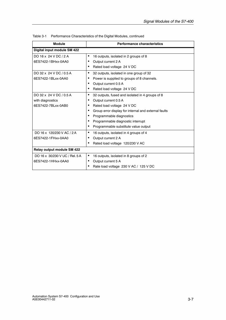
Table 3-1 Performance Characteristics of the Digital Modules, continued
Module Performance characteristics
Digital input module SM 422
DO 16 x 24 V DC / 2 A
6ES7422-1BHxx-0AA0
• 16 outputs, isolated in 2 groups of 8
• Output current 2 A
• Rated load voltage 24 V DC
DO 32 x 24 V DC / 0.5 A
6ES7422-1BLxx-0AA0
• 32 outputs, isolated in one group of 32
• Power is supplied to groups of 8 channels.
• Output current 0.5 A
• Rated load voltage 24 V DC
DO 32 x 24 V DC / 0.5 A
with diagnostics
6ES7422-7BLxx-0AB0
• 32 outputs, fused and isolated in 4 groups of 8
• Output current 0.5 A
• Rated load voltage 24 V DC
• Group error display for internal and external faults
• Programmable diagnostics
• Programmable diagnostic interrupt
• Programmable substitute value output
DO 16 x 120/230 V AC / 2A
6ES7422-1FHxx-0AA0
• 16 outputs, isolated in 4 groups of 4
• Output current 2 A
• Rated load voltage 120/230 V AC
Relay output module SM 422
DO 16 x 30/230 V UC / Rel. 5 A
6ES7422-1HHxx-0AA0
• 16 outputs, isolated in 8 groups of 2
• Output current 5 A
• Rate load voltage 230 V AC / 125 V DC
Signal Modules of the S7-400
3-8Automation System S7-400 Configuration and Use
A5E00442711-02
Performance Characteristics of the Analog Modules
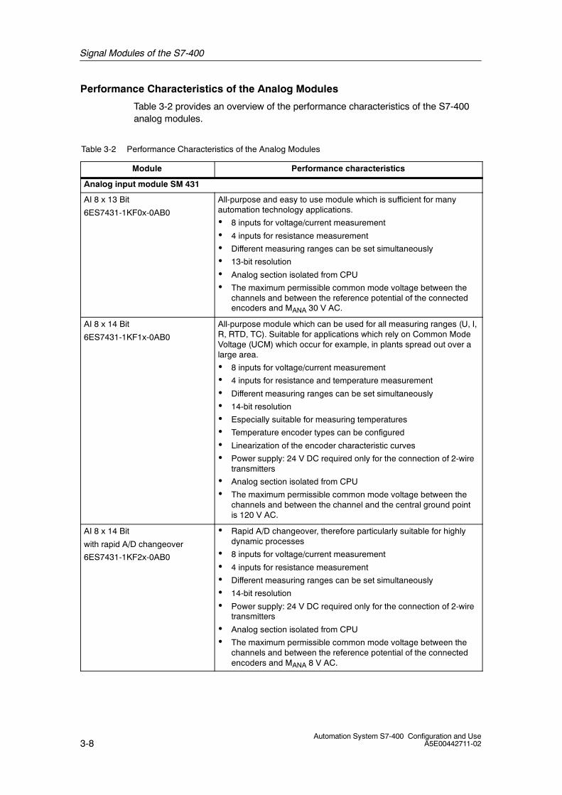
Table 3-2 provides an overview of the performance characteristics of the S7-400analog modules.
Table 3-2 Performance Characteristics of the Analog Modules
Module Performance characteristics
Analog input module SM 431
AI 8 x 13 Bit
6ES7431-1KF0x-0AB0
All-purpose and easy to use module which is sufficient for manyautomation technology applications.
• 8 inputs for voltage/current measurement
• 4 inputs for resistance measurement
• Different measuring ranges can be set simultaneously
• 13-bit resolution
• Analog section isolated from CPU
• The maximum permissible common mode voltage between thechannels and between the reference potential of the connectedencoders and MANA 30 V AC.
AI 8 x 14 Bit
6ES7431-1KF1x-0AB0
All-purpose module which can be used for all measuring ranges (U, I,R, RTD, TC). Suitable for applications which rely on Common ModeVoltage (UCM) which occur for example, in plants spread out over alarge area.
• 8 inputs for voltage/current measurement
• 4 inputs for resistance and temperature measurement
• Different measuring ranges can be set simultaneously
• 14-bit resolution
• Especially suitable for measuring temperatures
• Temperature encoder types can be configured
• Linearization of the encoder characteristic curves
• Power supply: 24 V DC required only for the connection of 2-wiretransmitters
• Analog section isolated from CPU
• The maximum permissible common mode voltage between thechannels and between the channel and the central ground pointis 120 V AC.
AI 8 x 14 Bit
with rapid A/D changeover
6ES7431-1KF2x-0AB0
• Rapid A/D changeover, therefore particularly suitable for highlydynamic processes
• 8 inputs for voltage/current measurement
• 4 inputs for resistance measurement
• Different measuring ranges can be set simultaneously
• 14-bit resolution
• Power supply: 24 V DC required only for the connection of 2-wiretransmitters
• Analog section isolated from CPU
• The maximum permissible common mode voltage between thechannels and between the reference potential of the connectedencoders and MANA 8 V AC.

Signal Modules of the S7-400
3-9Automation System S7-400 Configuration and UseA5E00442711-02
Table 3-2 Performance Characteristics of the Analog Modules, continued
Module Performance characteristics
AI 16 x 13 Bit
6ES7431-0HHxx-0AB0
Simple module for current and voltage measurement, offers highchannel density at a very low channel price.
• 16 inputs for voltage/current measurement
• Different measuring ranges can be set simultaneously
• 13-bit resolution
• Analog section non-isolated from CPU
• The maximum permissible common mode voltage between thechannels and the reference potentials of the connected encodersand central ground point is 2 V AC/DC.
AI 16 x 16 Bit
6ES7431-7QHxx-0AB0
Can be used univerally due to its ability to cover all measuring ranges(U, I, R, RTD, TC). Suitable for applications requiring higher andhighest precision and resolution, for example, in process engineeringplants.
• 16 inputs for voltage/current and temperature measurement withthermocouples (TC)
• 8 inputs for resistance and temperature measurement withresistance thermometers (RTD)
• Different measuring ranges can be set simultaneously
• 16-bit resolution
• Programmable diagnostics
• Programmable diagnostic interrupt
• Programmable interrupt for limit violation
• Programmable end-of-cycle interrupt
• Analog section isolated from CPU
• The maximum permissible common mode voltage between thechannels and between the channel and the central ground pointis 120 V AC.
AI 8 x RTD x 16 Bit
6ES7431-7KF1x-0AB0
Special module for temperature acquisition via resistancethermometer (RTD). Very high precision and resolution with a shortbasic conversion time (25 ms for all 8 channels) allow it to be usedeven in high-speed processes.
• 8 differential inputs for the resistance thermometer
• Programmable resistance thermometer
• Linearization of the resistance thermometer characteristic curves
• 16-bit resolution
• Update rate of 25 ms for 8 channels
• Programmable diagnostics
• Programmable diagnostic interrupt
• Programmable interrupt for limit violation
• Analog section isolated from CPU
• The maximum permissible common mode voltage between thechannel and the central ground point is 120 V AC.
Signal Modules of the S7-400
3-10Automation System S7-400 Configuration and Use
A5E00442711-02
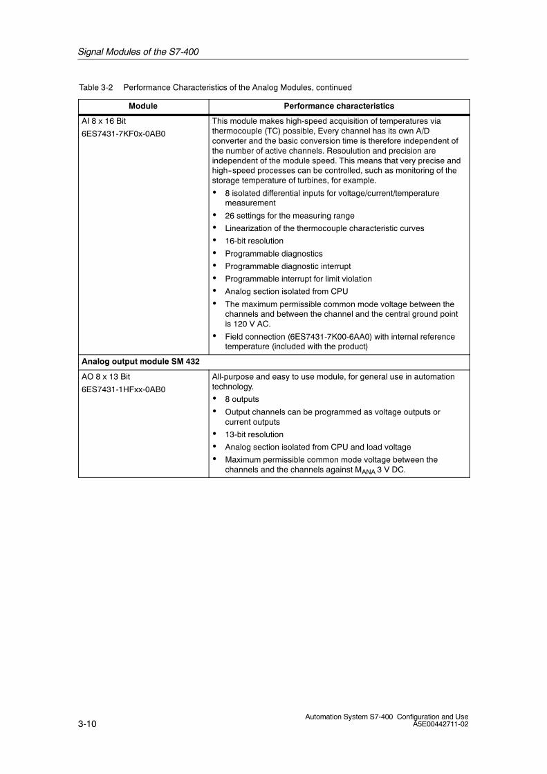
Table 3-2 Performance Characteristics of the Analog Modules, continued
Module Performance characteristics
AI 8 x 16 Bit
6ES7431-7KF0x-0AB0
This module makes high-speed acquisition of temperatures viathermocouple (TC) possible, Every channel has its own A/Dconverter and the basic conversion time is therefore independent ofthe number of active channels. Resoulution and precision areindependent of the module speed. This means that very precise andhigh--speed processes can be controlled, such as monitoring of thestorage temperature of turbines, for example.
• 8 isolated differential inputs for voltage/current/temperaturemeasurement
• 26 settings for the measuring range
• Linearization of the thermocouple characteristic curves
• 16-bit resolution
• Programmable diagnostics
• Programmable diagnostic interrupt
• Programmable interrupt for limit violation
• Analog section isolated from CPU
• The maximum permissible common mode voltage between thechannels and between the channel and the central ground pointis 120 V AC.
• Field connection (6ES7431-7K00-6AA0) with internal referencetemperature (included with the product)
Analog output module SM 432
AO 8 x 13 Bit
6ES7431-1HFxx-0AB0
All-purpose and easy to use module, for general use in automationtechnology.
• 8 outputs
• Output channels can be programmed as voltage outputs orcurrent outputs
• 13-bit resolution
• Analog section isolated from CPU and load voltage
• Maximum permissible common mode voltage between thechannels and the channels against MANA 3 V DC.
4-1Automation System S7-400 Configuration and UseA5E00442711-02
Technological Functions of the S7-400
Overview
The following information is contained in this chapter:
• The technological functions provided by the function modules
• The technological functions provided by the software package
4
Technological Functions of the S7-400
4-2Automation System S7-400 Configuration and Use
A5E00442711-02
4.1 S7-400 - The Right Solution for Every Technological Task
Introduction
Automation tasks with high technological requirements demand special solutionsthat can be simply and economically integrated into the system.
For the S7-400 automation system, the available function modules can handleeven the most complex process because that are specialized for specific tasks.
Another way to realize technological functions is the integration of softwarepackages in the controller. The wide-range of packages available enable you tocover a wide field of applications quickly and with little effort.

Technological Functions of the S7-400
4-3Automation System S7-400 Configuration and UseA5E00442711-02
4.2 Function Modules - the Specialists
Introduction
Function modules enable you to find fast solutions for complex technological tasks.The function modules use the same address ranges and are configured in thesame way as signal modules using STEP 7. Function modules are offered for thefollowing application areas:
• Counting and frequency measurement
• Positioning
• Controlling
Counting and Frequency Measurement
The following function module is available for counting and frequencymeasurement tasks:
• FM 450 counter module for fast counting up to 500 kHz cut-off frequency,2-channel
Positioning
The following function modules are available for positioning tasks depending on theapplication:
• FM 451 rapid/creep positioning, 3-channel
• FM 452 electronic cam controller, 1-channel
• FM 453 positioning with stepping motors, 3-channel
• FM 454 positioning with servomotors, 3-channel
• FM 458-1 DP high-dynamic closed-loop positioning
Controlling
The following function module is available for controlling tasks:
• FM 455 with 16 channels
Access to Function Modules
Function modules are accessed via function blocks that are called from the userprogram.
Technological Functions of the S7-400
4-4Automation System S7-400 Configuration and Use
A5E00442711-02
Advantages
The realization of technological functions using function modules offers thefollowing advantages:
• Tasks do not depend on the CPU and are therefore processed independent ofthe cycle time.
• Economic solutions
• Uniform configuration of all function modules using STEP 7 reducesengineering costs
• Easy, convenient operation due to common data storage

Technological Functions of the S7-400
4-5Automation System S7-400 Configuration and UseA5E00442711-02
4.3 Counting with the FM 450-1
Introduction
You can use the intelligent counter module, FM 450-1, for a wide range ofhigh-frequency counting tasks. It provides the following features to relieve the loadon the CPU:
• Direct evaluation of the signals from incremental encoders
• Direct evaluation of gate signals such as those from photoelectric barriers viaintegrated digital inputs
• Comparison operations and response output via integrated digital outputs
Counter functions of the FM 450-1
The FM 450-1 provides you with the following counter functions:
• Continuous counting
• Single counting
• Periodic counting
Performance Characteristics of the FM 450-1
The FM 450-1 has the following performance characteristics:
• Maximum counting frequency
-- 500 kHz with 5 V encoders
-- 200 kHz with 24 V encoders
• Maximum counting width
-- 32 bit
• Connectable encoders
-- 5-V incremental encoder with RS 422 interface
-- 24 V incremental encoder
-- 24 V directional encoder
-- 24 V pulse generator

Technological Functions of the S7-400
4-6Automation System S7-400 Configuration and Use
A5E00442711-02
4.4 Controlled Positioning with the FM 451
Introduction
The FM 451 positioning module is used to set and position mechanical axes withthe rapid/creep method. It provides the following features to relieve the load on theCPU:
• Monitoring of standstill and target approach
• Setting of actual value / actual value on-the-fly
• Zero offset
• Setting of reference point
• Deleting of distance remaining
Functions of the FM 451
The FM 451 provides you with the following functions:
• Configuration in inching mode
• Absolute/relative incremental approach
• Reference point approach
• Loop traverse
Performance characteristics of the FM 451
The FM 451 has the following performance characteristics:
• Number of axes:
-- 3 linear or rotary axis
• Inputs and outputs
-- 4 digital inputs per axis
-- 4 digital outputs per axis
• Typical drives
-- Standard motor, contactor controlled
-- Standard motor with frequency converter, e.g. Micromaster
-- Asynchronous motor connected to power unit with vector control
• Connectable encoders:
-- Incremental encoder 5 V differential signal, symmetrical
-- Incremental encoder with 24 V signal, asymmetrical
-- SSI absolute encoder
Technological Functions of the S7-400
4-7Automation System S7-400 Configuration and UseA5E00442711-02
4.5 Cam Controlling with the FM 452
Introduction
The FM 452 is an electronic cam controller that triggers functions based onposition or time. It provides the following features to relieve the load on the CPU:
• Setting and resetting of electronic cams based on actual values
Functions of the FM 452
The FM 452 provides you with the following functions:
• Position-based cam controlling
• Time-based cam controlling
Each can be implemented as a position or time cam. You can optionally configuretwo counter cam tracks and one brake cam track.
Performance characteristics of the FM 452
The FM 452 has the following performance characteristics:
• Number of axes:
-- 1 linear or rotary axis
• Number of cams
-- Configurable, 16, 32, 64 or 128
• Inputs and outputs
-- 11 digital inputs, 8 of these enable inputs
-- 16 digital outputs as cam tracks
• Connectable encoders:
-- Incremental encoder 5 V differential signal, symmetrical
-- Incremental encoder with 24 V signal, asymmetrical
-- SSI absolute encoder
Technological Functions of the S7-400
4-8Automation System S7-400 Configuration and Use
A5E00442711-02
4.6 Controlled Positioning with the FM 453
Introduction
The FM 453 is a positioning module for servo-controlled positioning with steppingmotors and servomotors. It provides the following features to relieve the load onthe CPU:
• Actual-value acquisition and servo-control positioning
• Data storage on the FM 453
Functions of the FM 453
The FM 453 provides you with the following functions:
• Configuration in inching mode
• Controlling
• Reference point approach
• Incremental mode, relative
• Manual data input (MDI)
• Automatic and automatic single block
Performance characteristics of the FM 453
The FM 453 has the following performance characteristics:
• Number of axes:
-- 3 linear or rotary axes
• Inputs and outputs
-- 4 digital inputs per axis
-- 4 digital outputs per axis
• Typical drives
-- Asynchronous motor
-- DC motor
• Connectable encoders for positioning with servomotors:
-- Incremental encoder 5 V differential signal, symmetrical
-- SSI absolute encoder

Technological Functions of the S7-400
4-9Automation System S7-400 Configuration and UseA5E00442711-02
4.7 Controlling with the FM 455
Introduction
The FM 455 is a universal controller module. The FM 455C is a continuouscontroller for controlling analog actuators and the FM 455S is a step controller forcontrolling motor-driven actuators. The FM 455 provides the following features torelieve the load on the CPU:
• Temperature controller (fuzzy controller)
• PID controller
Functions of the FM 455
The FM 455 provides you with the following functions:
• Fixed setpoint control
• Follow-up control
• Three-component control
• Cascade control
• Ratio control
• Blending control
• Split-range control

Technological Functions of the S7-400
4-10Automation System S7-400 Configuration and Use
A5E00442711-02
Performance characteristics of the FM 455
The FM 455 has the following performance characteristics:
• Number of controllers:
-- 16 independent controllers in 16 channels
• Inputs and outputs
-- 16 digital inputs
-- 32 digital outputs on the FM 455S
-- 16 analog inputs
-- 16 analog outputs on the FM 455C
-- 1 reference junction input for compensation of thermocouples
• Connectable sensors for actual value acquisition:
-- Current sensor 0 to 20 mA
-- Current sensor 4 to 20 mA
-- Voltage sensor 0 to 10 V
-- Pt 100, -200 ... 850 °C
-- Pt 100, -200 ... 556 °C, double resolution
-- Pt 100, -200 ... 130 °C, quadruple resolution
-- Thermocouple types B, J, K, R und S and free thermocouple

Technological Functions of the S7-400
4-11Automation System S7-400 Configuration and UseA5E00442711-02
4.8 High-dynamic Closed-loop Positioning with the FM 458-1DP
Introduction
With the FM 458-1 DP application module you can configure high-performancecontrolling and technological applications in a SIMATIC S7-400. Together with twoadditional plug-in expansion modules, the FM 458-1 DP allows the implementationof a a large number of high-dynamic applications, especially drive-relatedapplications.
Functions of the FM 458-1 DP
The FM 458-1 DP provides you with the following functions:
• Torque controls
• Speed controls
• Position and closed-loop position controls
Performance characteristics of the FM 458-1 DP
The FM 458-1 DP has the following performance characteristics:
• Cycle time 0.5 ms typical
• DRAM user memory (16 MB) 12 MB for user programs
• SRAM (256 KB)
• Exchangeable program memory MMC (2, 4, or 8 MB)
• 8 interrupt tasks can be called via 8 digital inputs.
• Profibus DP Interface
• RS-232 interface (V.24)
• LE bus
Configuring the FM 458-1 DP
Control engineering functions can be easily configured using the graphicconfiguration interface, CFC (Continuous Function Chart). You can take blocksfrom a library comprising approximately 250 function blocks and place them on apage using simple drag-and-drop. The block I/Os are interconnected by clicking onan output and an input. For inputs assigned with a fixed value and are not to beconnected, the value is specified in a parameter assignment dialog.
The configuration created in this way is then compiled by CFC, the graphicconfiguration interface, and downloaded to the FM 458-1 DP application module.
Technological Functions of the S7-400
4-12Automation System S7-400 Configuration and Use
A5E00442711-02
Expansion Module EXM 438-1
The EXM 438-1 I/O expansion module provides the following additional inputs andoutputs as well as interfaces for incremental and absolute value encoders:
• 16 digital inputs, 24 V
• 8 digital outputs, 24 V
• 5 analog inputs
• 4 analog outputs 12 bit
• 4 analog outputs 16 bit
• 8 interfaces for incremental encoders
• 4 interfaces for absolute value encoders, SSI or EnDat
Expansion Module EXM 448
The communication expansion module EXM 448 has the following interfaces:
• Profibus DP, master or slave
• RS 232
You can optionally use MASTERDRIVES plug-in modules, e.g. SLB for SIMOLINKand SBM2 for higher-resolution multi-turn encoders.
Expansion Module EXM 448-2
The communication expansion module EXM 448-2 has the following interfaces:
• SIMOLINK with master function for controlling up to 200 MASTERDRIVES
• SIMOLINK with slave function for fast coupling to SIMADYN D or multiple FM458-1 DP

Technological Functions of the S7-400
4-13Automation System S7-400 Configuration and UseA5E00442711-02
4.9 Software Solutions
Introduction
Some automation tasks can be quickly and easily solved by integrating blocks inthe CPU. It is important within this context for the adopted solution to be supportedby a user-friendly graphic interface. This chapter gives you an overview of thenumerous solutions for technological tasks provided by software packages.
Easy Motion Control
Easy Motion Control consists of a set of function blocks (FBs) that containalgorithms for closed-loop positioning. You can assemble your positioner myinterconnected individual blocks.
The function blocks from Easy Motion Control were developed according to the”Technical Specification V1.0” from PLCopen.
Easy Motion Control is used to position an axis on a target with selectableacceleration, velocity and deceleration or move it at constant velocity. The requiredtravel movements are started by triggering travel function blocks.
Easy Motion Control provides the following functions:
• Inching
• Reference point approach
• Absolute/relative positioning
• Electronic gears
• Reference point setting
• Velocity override
• Closed-loop controlling
• Simulation
• Preassembled drivers for encoders or analog output modules
Technological Functions of the S7-400
4-14Automation System S7-400 Configuration and Use
A5E00442711-02
Modular PID Control
Modular PID Control consists of a set of function blocks (FBs) that containalgorithms for generating control engineering functions. You can assemble yourcontroller structure my interconnected individual blocks.
The block library is supplemented by a number of ready-to-use controllerstructures (single-loop fixed setpoint controller, ratio controller etc.) in the form ofexamples. You can copy and adapt these examples to suit your own control task.
A wide-range of plant controls can be easily configured using the control calldistributor. This is especially useful when numerous control loops need to beconfigured at varying intervals - but still equidistant - based on the inertia of therespective process. This also ensures that the workload on the CPU is evenlydistributed.
To help you install and test individual control loops, the Modular PID Control Toolconfiguration software is provided. It contains a loop monitor, a graphic plotter foroperating and monitoring process variables, and an algorithm for optimizing thePID parameters.
Standard PID Control
Standard PID Control consists of two function blocks (FBs) and a function (FC),which contain the algorithms for generating control and signal-processing functionsfor continuous or step controllers.
The behavior of the controller itself and the properties of the functions in themeasuring and adjusting channel are realized or simulated by means of thenumerical algorithms of the function block. The data required for these cycliccalculations is saved in data blocks for the specific control loop. An FB is onlyrequired once to create several controllers.
There are also ready-to-use controller structures (step controller, blend controller,cascade controller etc.) in the form of examples. You can copy and adapt theseexamples to suit your own control task.
A wide-range of plant controls can be easily configured using the control calldistributor. This is especially useful when numerous control loops need to beconfigured at varying intervals - but still equidistant - based on the inertia of therespective process. This also ensures that the workload on the CPU is evenlydistributed.

Technological Functions of the S7-400
4-15Automation System S7-400 Configuration and UseA5E00442711-02
PID Temperature Control
PID Temperature Control consists of two function blocks (FBs), which contain thealgorithms for generating control and signal-processing functions for temperaturecontrollers.
The respective blocks are used to assemble the following controllers:
• Temperature controller for actuators with a continuous or pulsed input signal.This controller block also includes a self-tuning function for the PI/PIDparameters.
• Temperature step controller for actuators with an integral component such as apositioning motor.
The temperature controller operates with the PID control algorithm and featuresadditional functions for temperature processes. The controller supplies analogmanipulated values and pulse-duration modulated actuating signals. The controlleroutputs signals to one actuator; in other words, you can use the controller for eithera pure heating process or a pure cooling process.
To improve the control response, the block includes a control zone and reduction ofthe P component if there is a setpoint step change. The controller can set thePI/PID parameters itself using a controller tuning function.
The temperature step controller operates with the PI control algorithm of thesampling controller, supplemented by function groups for generating the binaryoutput signal from the analog actuating signal. You can also use the controller in acascade control as a secondary position controller, for example, for temperaturecontrol with heating power regulation using pulse-break activation and coolingcontrol using a butterfly valve.
You can externally influence the manipulated value signals of the temperature stepcontroller. The step controller operates without a position feedback signal.
PID Self-Tuner
The PID Self-Tuner enables you to expand the following PID controllers fromSIMATIC S7 to create self-tuning PID controllers.
• Standard PID Control
• Modular PID Control
• Controller module FM 455
PID Self-Tuners are particularly useful for the following:
• Temperature controls
• Liquid level controls
• Flow controls (not for pure control value regulation)
Technological Functions of the S7-400
4-16Automation System S7-400 Configuration and Use
A5E00442711-02
PMC (Process Monitoring and Controlling)
Many operating and monitoring functions demand signals to be monitored andmessages to be displayed when they change. This functionality can be quickly andeasily realized with this software package.
In the configuration phase you determine which binary signals should be monitoredfor change, whether it be inputs, outputs, memory bits or data bits. You canconfigure up to 2048 signals, depending on the CPU. Each operand is assigned isown message text. The CPU monitors the configured signals in a specific timepattern (scan cycle). Each change to the configured signals is reported by the CPUto the connected HMI device, which then displays the assigned message texts.
In addition to the change messages, the CPU can send up to ten values from theCPU to the HMI station.
5-1Automation System S7-400 Configuration and UseA5E00442711-02
Interfaces, Networks and DataCommunication for the S7-400
In this Chapter
The following information is contained in this chapter:
• The connection of multiple automation systems via the MPI interface of theCPU. An example is provided to show how easy it is to realize datacommunication among three central controller modules.
• The I/O connection via PROFIBUS DP to couple S7-400 with the distributed I/Oand devices from the SIMATIC S5 automation series.
• The I/O connection via PROFINET IO to interface distributed I/O directly toIndustrial Ethernet.
• The point-to-point communication via the communication modules CP 440,CP 441-1 and CP 441-2
• Data exchange via communication functions
5

Interfaces, Networks and Data Communication for the S7-400
5-2Automation System S7-400 Configuration and Use
A5E00442711-02
5.1 The Right Solution for Every Communication Task.
Introduction
The demands placed on modern automation systems can no longer be met bycentralized solutions alone. But relying on autonomous systems and subsystemsbrings problems of data communication among the individual units.
Communication Solutions
S7-400 offers numerous solutions for communication. The following characteristicscan be underscored:
• A tiered range of performance (volume capabilities)
• A convenient user interface integrated in STEP 7
• Integration of communication tasks in the components
Data communication can be performed via the following:
• Integrated MPI/DP interfaces in the CPU
• Communication modules for a variety of networks
-- CP 443-5 on PROFIBUS
-- CP 443-1 on Industrial Ethernet
-- CP 440, CP 441-1 and CP 441-2 for point-to-point -connection
Using system functions (SFCs and SFBs), you can perform data communicationusing the user program and a variety of communication networks. The SFBs andSFCs are integrated in the operating system of the CPU.
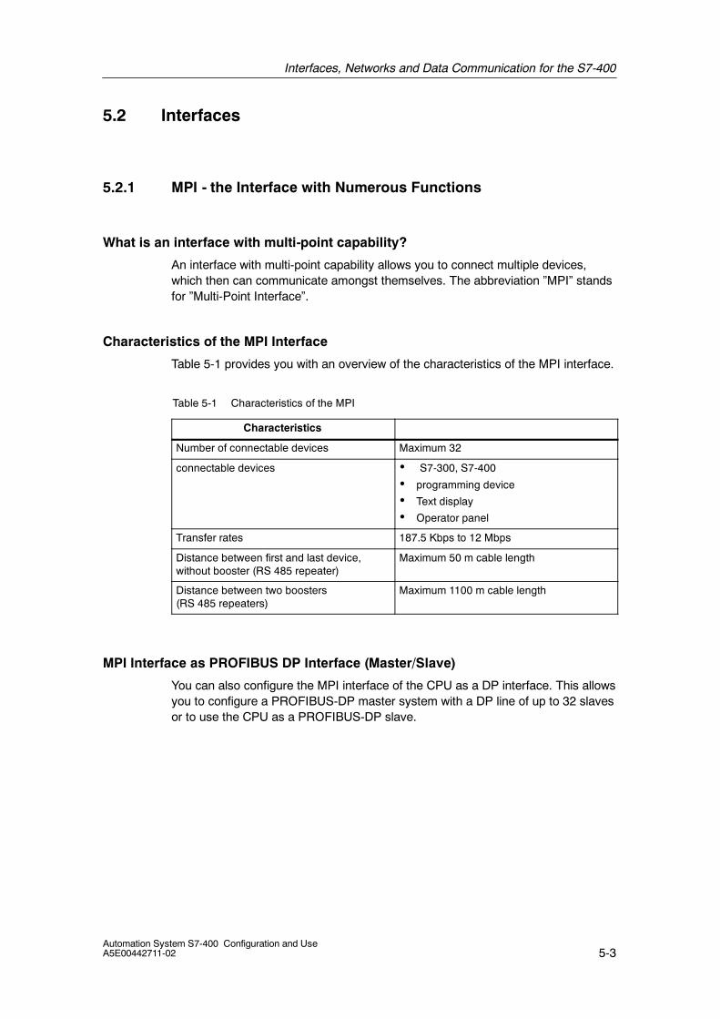
Interfaces, Networks and Data Communication for the S7-400
5-3Automation System S7-400 Configuration and UseA5E00442711-02
5.2 Interfaces
5.2.1 MPI - the Interface with Numerous Functions
What is an interface with multi-point capability?
An interface with multi-point capability allows you to connect multiple devices,which then can communicate amongst themselves. The abbreviation ”MPI” standsfor ”Multi-Point Interface”.
Characteristics of the MPI Interface
Table 5-1 provides you with an overview of the characteristics of the MPI interface.
Table 5-1 Characteristics of the MPI
Characteristics
Number of connectable devices Maximum 32
connectable devices • S7-300, S7-400
• programming device
• Text display
• Operator panel
Transfer rates 187.5 Kbps to 12 Mbps
Distance between first and last device,without booster (RS 485 repeater)
Maximum 50 m cable length
Distance between two boosters(RS 485 repeaters)
Maximum 1100 m cable length
MPI Interface as PROFIBUS DP Interface (Master/Slave)
You can also configure the MPI interface of the CPU as a DP interface. This allowsyou to configure a PROFIBUS-DP master system with a DP line of up to 32 slavesor to use the CPU as a PROFIBUS-DP slave.
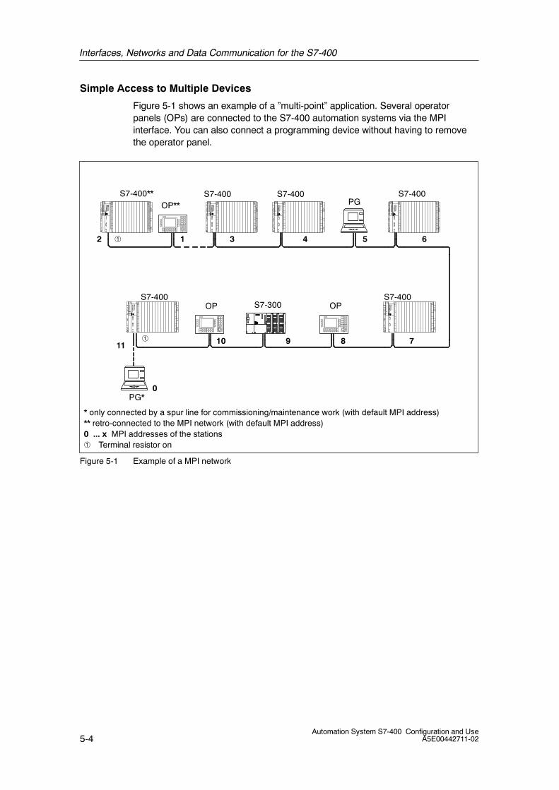
Interfaces, Networks and Data Communication for the S7-400
5-4Automation System S7-400 Configuration and Use
A5E00442711-02
Simple Access to Multiple Devices
Figure 5-1 shows an example of a ”multi-point” application. Several operatorpanels (OPs) are connected to the S7-400 automation systems via the MPIinterface. You can also connect a programming device without having to removethe operator panel.
* only connected by a spur line for commissioning/maintenance work (with default MPI address)** retro-connected to the MPI network (with default MPI address)0 ... x MPI addresses of the stations
Terminal resistor on
S7-400** S7-400 S7-400 S7-400
S7-400 S7-400
0
11 78910
12 3 4 5 6
PG*
OP OP
PGOP**
S7-300
Figure 5-1 Example of a MPI network
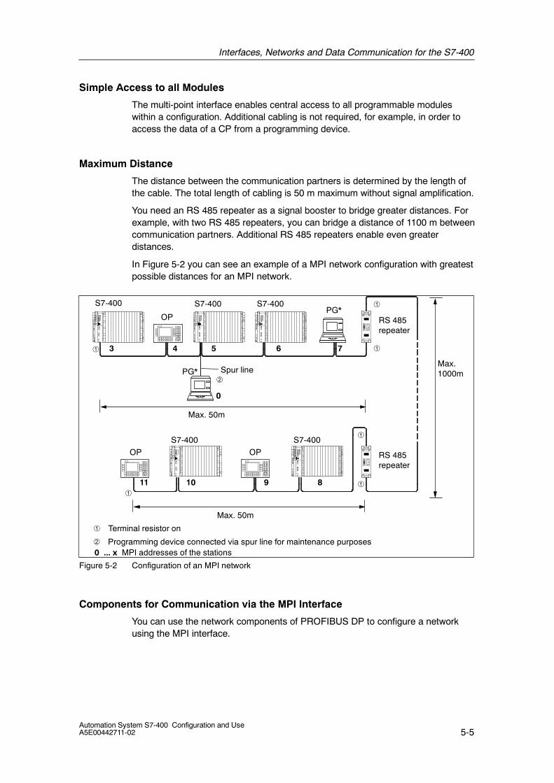
Interfaces, Networks and Data Communication for the S7-400
5-5Automation System S7-400 Configuration and UseA5E00442711-02
Simple Access to all Modules
The multi-point interface enables central access to all programmable moduleswithin a configuration. Additional cabling is not required, for example, in order toaccess the data of a CP from a programming device.
Maximum Distance
The distance between the communication partners is determined by the length ofthe cable. The total length of cabling is 50 m maximum without signal amplification.
You need an RS 485 repeater as a signal booster to bridge greater distances. Forexample, with two RS 485 repeaters, you can bridge a distance of 1100 m betweencommunication partners. Additional RS 485 repeaters enable even greaterdistances.
In Figure 5-2 you can see an example of a MPI network configuration with greatestpossible distances for an MPI network.
Max. 50m
Max. 50m
Max.1000m
Terminal resistor on
Programming device connected via spur line for maintenance purposes0 ... x MPI addresses of the stations
RS 485repeater
RS 485repeater
S7-400 S7-400 S7-400
S7-400 S7-400
Spur line
0
11
7
8910
3 4 5 6
OP
PG*
PG*
OP
OP
Figure 5-2 Configuration of an MPI network
Components for Communication via the MPI Interface
You can use the network components of PROFIBUS DP to configure a networkusing the MPI interface.

Interfaces, Networks and Data Communication for the S7-400
5-6Automation System S7-400 Configuration and Use
A5E00442711-02
5.2.2 I/O Interface via PROFIBUS DP
Introduction
The flexibility of a controller is a crucial factor for the productivity of amanufacturing plant. To achieve the highest degree of flexibility, complex controltasks can be grouped and distributed to several devices. This brings the followingadvantages:
• Signals can be acquired locally, saving costs.
• You get easy-to-handle small units. You can easily configure, commission,perform diagnostics, change, operation and monitor the entire process.
• You have more control over your plant. If a unit fails, the remaining system cancontinue operating.
The solution is called PROFIBUS DP.
You can meet the increasing demand on data volume and the associated transferspeeds needed for this with PROFIBUS DP.
With the DP interface of the S7-400 CPU, connecting ET 200 distributed I/O andstandard slaves poses no problem.
Use and Area of Application
I/O interfacing via PROFIBUS DP can be used in the following situations:
• You want a distributed configuration for you plant.
• You want to use the S7-400 with the tried-and-proven components of the ET200 distributed I/O system.
Typical Configuration
PROFIBUS DP consists of a DP master and multiple DP slaves, PROFIBUS withthe DP protocol and STEP 7 for assigning parameters to the PROFIBUS DPconfiguration.
• DP master: The DP master links the controller with the distributed I/O systems.It exchanges data with the distributed I/O via PROFIBUS DP and monitors thefieldbus.
• DP slaves: I/O devices are connected as DP slaves. The DP slaves prepare theencoder and actuator data on-site so that they can be transmitted viaPROFIBUS DP.
• Programming device / PC: STEP 7, installed on the programming device or PC,is used to configure the assembly and put PROFIBUS DP into service.
S7-400 as DP Master / DP Slave
You can integrate the S7-400 as a DP master or a DP slave in PROFIBUS DP.
Interfaces, Networks and Data Communication for the S7-400
5-7Automation System S7-400 Configuration and UseA5E00442711-02
DP slaves
Numerous stations are available as DP slaves, for example:
• Distributed I/O from the ET 200 series
• Drives (power converters, frequency converters)
• CNC controllers
• Standard slaves from other manufacturers
Characteristics of PROFIBUS DP
Table provides you with an overview of the characteristics of the PROFIBUS DP.
Table 5-2 Characteristics of PROFIBUS DP
Connectable devices Field devices such as drives, valves,distributed I/O
Maximum number of slaves 125
Maximum data volume per slave 244 bytes inputs, 244 bytes outputs
Transfer rates 9.6 Kbps to 12 Mbps
Typical reaction time 1 ms (at 12 Mbps and 16 DP slaves)
Transmission medium Shielded two-wire cables orfiber-optic cables (glass or plastic)
Distance Two-wire cable: 9.6 kmFiber-optic cable: 23.8 km
Typical degree of protection for the slavemodule
IP20 to IP67
Standard PROFIBUS according to IEC 61158 /IEC 61784-1:2002 Ed1 CP 3/1
Access to Distributed I/O
I/O is addressed via PROFIBUS DP as easily as the central I/O in the CPU.
The distributed I/O modules have the same functions as the modules connecteddirectly to the central rack, for example:
• You can trigger diagnostic interrupts.
• You can trigger process interrupts.
• You can assign parameters with the user program.

Interfaces, Networks and Data Communication for the S7-400
5-8Automation System S7-400 Configuration and Use
A5E00442711-02
Example of a PROFIBUS DP Configuration
Figure 5-5 shows an example of a PROFIBUS DP configuration with devices fromthe SIMATIC S7, SIMATIC S5 and ET 200 series. The S7-400 is the DP master inthis configuration, all other devices are DP slaves.
* only connected by a spur line for commissioning/maintenance work (with PROFIBUS DP address= 0)
0 ... x PROFIBUS DP addresses of the stations
S7-400 withCPU 414-2-DPas DP master ET 200M
0 678
1 2 3 4 5
PG*
OP
PGET 200M S5-95U
ET 200BET 200B
Terminal resistor on
Figure 5-3 Example of a PROFIBUS DP network
5.2.3 I/O Interface via PROFINET IO
Introduction
Full communication from the field to the control center is one of the most importantdemands in automation engineering today. The technology employed must meetthe following requirements:
• Standardized connection systems
• Uniform network management
• IT access mechanisms
• Comprehensive diagnostic options

Interfaces, Networks and Data Communication for the S7-400
5-9Automation System S7-400 Configuration and UseA5E00442711-02
PROFINET IO
PROFINET is an open and vendor-independent Industrial Ethernet standard forautomation. PROFINET IO allows you to connect I/O directly to Industrial Ethernet.
Typical Configuration
PROFINET IO operates with a provider-consumer model. The provider is thesender, who transmits his data without request from the communication partner.The consumer process the data. The assignment as a provider or consumer isspecified in the configuration.
The following device types are used for PROFINET IO.
• IO controller: The controller of the automation system
• IO devices: The distributed I/O that is assigned to an IO controller.
• IO supervisor: A programming device, PC or HMI device for commissioning anddiagnostics.
• IE PB Link PN IO: This enables the integration of existing PROFIBUS fieldbussystem without having to change the existing devices.
Configuration
You configure the IO devices with STEP 7. The devices are uniquely identified bydescription files (General Station Description, GSD). The description files can beimported in STEP 7.
Communication Processor CP 443-1 Advanced
The communication processor CP 443-1 Advanced is designed for operation in anS7-400 automation system (not in H systems or H CPUs). It enables theconnection of the S7-400 to Industrial Ethernet.
With its services for PROFINET IO, CP 443-1 Advanced allows direct access toPROFINET IO devices via Industrial Ethernet
Characteristics of PROFINET IO
Table provides you with an overview of the characteristics of the PROFINET IO.
Table 5-3 Characteristics of PROFINET IO
Connectable devices Field devices such as drives, valves,distributed I/O
Maximum number of devices 125
Data record length Max. 1432 bytes
Transfer rates 100 Mbps switching technology
Typical reaction time 1 ms

Interfaces, Networks and Data Communication for the S7-400
5-10Automation System S7-400 Configuration and Use
A5E00442711-02
Table 5-3 Characteristics of PROFINET IO, continued
Transmission medium Shielded two-wire cables orfiber-optic cables (glass or plastic)
Cable length between network componentsor between terminals and networkcomponents
Two-wire cable: Max. 100 mMultimode fiber-optic cable: 3000 mMonomode fiber-optic cable: Max. 26 km
Standard PROFINET according to IEC 61158
Example of a PROFINET IO Configuration
Figure 5-5 shows an example of a PROFINET IO configuration with devices fromthe SIMATIC S7, SIMATIC S5 and ET 200 series.
S7-400 with CP 443-1Advanced as IO controller
ET 200M ET 200MET 200BET 200B
Programming deviceas IO supervisor
IE/PB LinkPN IO
ET 200S
PROFINET IO
PROFIBUS DP
Figure 5-4 Example of a PROFINET IO configuration
Interfaces, Networks and Data Communication for the S7-400
5-11Automation System S7-400 Configuration and UseA5E00442711-02
5.2.4 From point-to-point: CP 440, CP441-1 and CP 441-2
Introduction
The point-to-point connection is a high-performance, economic alternative to thebus systems. It enables the connection of barcode readers, scales and displays,for example. But it can also be used to interconnect to other automation systems.
Point-to-point with CP 441-1 and CP 441-2
You can select two communication modules (CP) for point-to-point connection:
• CP 440
• CP441-1 with a plug-in interface module
• CP441-2 with two plug-in interface modules
Plug-in interface modules
A variety of interface modules can be plugged into the CP. The following areavailable:
• TTY module
• RS 232C module
• RS 422/485 module
ASCII, 3964 (R) and RK 512 drivers are available as protocols.
Loadable Drivers
Additional loadable CP drivers are available for special protocols.

Interfaces, Networks and Data Communication for the S7-400
5-12Automation System S7-400 Configuration and Use
A5E00442711-02
5.3 Data Exchange via Communication Functions
Introduction
Data exchange via a variety of bus systems, such as MPI and Industrial Ethernet,PROFIBUS DP or point-to-point connection can be triggered and controlled in theuser program.
You determined the desired functionality for this program-driven communication bycalling a communication function in the user program. This might be a point in time,the amount of data or the transmission method.
Corresponding communication functions (SFCs, SFBs, loadable FC/FBs) areavailable on the S7-400 for data exchange.
SFCs for S7 Basic Communication via an MPI Subnet
You can transmit up to 76 bytes of data via an MPI subnet using these functions. Aconnection configuration is not necessary.
SFC Description
SFC 65SFC 66
X_SENDX_RCV
Secure transfer of a data block to the communication partner. Thismeans that data transmission is not completed until the receivefunction (X_RCV) in the communication partner has accepted thedata.
SFC 67 X_GET This SFC can be used to read a variable from a communicationpartner without having to place a corresponding SFC in thecommunication partner.
SFC 68 X_PUT This SFC can be used to write a variable to a communication partnerwithout having to place a corresponding SFC in the communicationpartner.
SFC 69 X_ABORT This SFC can be used to abort an existing link explicitly withouthaving to transfer data.
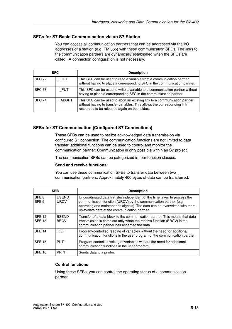
Interfaces, Networks and Data Communication for the S7-400
5-13Automation System S7-400 Configuration and UseA5E00442711-02
SFCs for S7 Basic Communication via an S7 Station
You can access all communication partners that can be addressed via the I/Oaddresses of a station (e.g. FM 355) with these communication SFCs. The links tothe communication partners are dynamically established when the SFCs arecalled. A connection configuration is not necessary.
SFC Description
SFC 72 I_GET This SFC can be used to read a variable from a communication partnerwithout having to place a corresponding SFC in the communication partner.
SFC 73 I_PUT This SFC can be used to write a variable to a communication partner withouthaving to place a corresponding SFC in the communication partner.
SFC 74 I_ABORT This SFC can be used to abort an existing link to a communication partnerwithout having to transfer variables. This allows the corresponding linkresources to be released again on both sides.
SFBs for S7 Communication (Configured S7 Connections)
These SFBs can be used to realize acknowledged data transmission viaconfigured S7 connection. The communication functions are not limited to datatransfer, additional functions can be used to control and monitor thecommunication partner. Communication is only possible within an S7 project.
The communication SFBs can be categorized in four function classes:
Send and receive functions
You can use these communication SFBs to transfer data between twocommunication partners. Approximately 400 bytes of data can be transferred.
SFB Description
SFB 8SFB 9
USENDURCV
Uncoordinated data transfer independent of the time taken to process thecommunication function (URCV) by the communication partner (e.g.operating and maintenance signals). The data can be overwritten with moreup-to-date data at the communication partner.
SFB 12SFB 13
BSENDBRCV
Transfer of a data block to the communication partner. This means that datatransmission is complete only when the receive function (BRCV) in thecommunication partner has accepted the data.
SFB 14 GET Program-controlled reading of variables without the need for additionalcommunication functions in the user program of the communication partner.
SFB 15 PUT Program-controlled writing of variables without the need for additionalcommunication functions in the user program.
SFB 16 PRINT Sends data to a printer.
Control functions
Using these SFBs, you can control the operating status of a communicationpartner.
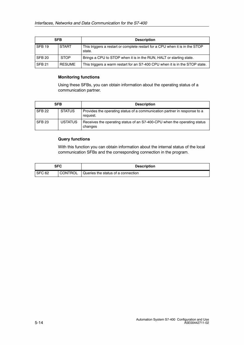
Interfaces, Networks and Data Communication for the S7-400
5-14Automation System S7-400 Configuration and Use
A5E00442711-02
SFB Description
SFB 19 START This triggers a restart or complete restart for a CPU when it is in the STOPstate.
SFB 20 STOP Brings a CPU to STOP when it is in the RUN, HALT or starting state.
SFB 21 RESUME This triggers a warm restart for an S7-400 CPU when it is in the STOP state.
Monitoring functions
Using these SFBs, you can obtain information about the operating status of acommunication partner.
SFB Description
SFB 22 STATUS Provides the operating status of a communication partner in response to arequest.
SFB 23 USTATUS Receives the operating status of an S7-400-CPU when the operating statuschanges
Query functions
With this function you can obtain information about the internal status of the localcommunication SFBs and the corresponding connection in the program.
SFC Description
SFC 62 CONTROL Queries the status of a connection
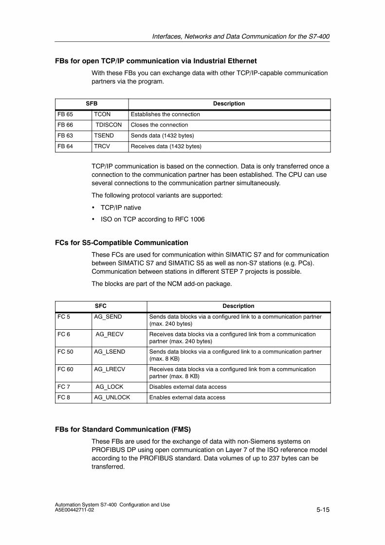
Interfaces, Networks and Data Communication for the S7-400
5-15Automation System S7-400 Configuration and UseA5E00442711-02
FBs for open TCP/IP communication via Industrial Ethernet
With these FBs you can exchange data with other TCP/IP-capable communicationpartners via the program.
SFB Description
FB 65 TCON Establishes the connection
FB 66 TDISCON Closes the connection
FB 63 TSEND Sends data (1432 bytes)
FB 64 TRCV Receives data (1432 bytes)
TCP/IP communication is based on the connection. Data is only transferred once aconnection to the communication partner has been established. The CPU can useseveral connections to the communication partner simultaneously.
The following protocol variants are supported:
• TCP/IP native
• ISO on TCP according to RFC 1006
FCs for S5-Compatible Communication
These FCs are used for communication within SIMATIC S7 and for communicationbetween SIMATIC S7 and SIMATIC S5 as well as non-S7 stations (e.g. PCs).Communication between stations in different STEP 7 projects is possible.
The blocks are part of the NCM add-on package.
SFC Description
FC 5 AG_SEND Sends data blocks via a configured link to a communication partner(max. 240 bytes)
FC 6 AG_RECV Receives data blocks via a configured link from a communicationpartner (max. 240 bytes)
FC 50 AG_LSEND Sends data blocks via a configured link to a communication partner(max. 8 KB)
FC 60 AG_LRECV Receives data blocks via a configured link from a communicationpartner (max. 8 KB)
FC 7 AG_LOCK Disables external data access
FC 8 AG_UNLOCK Enables external data access
FBs for Standard Communication (FMS)
These FBs are used for the exchange of data with non-Siemens systems onPROFIBUS DP using open communication on Layer 7 of the ISO reference modelaccording to the PROFIBUS standard. Data volumes of up to 237 bytes can betransferred.
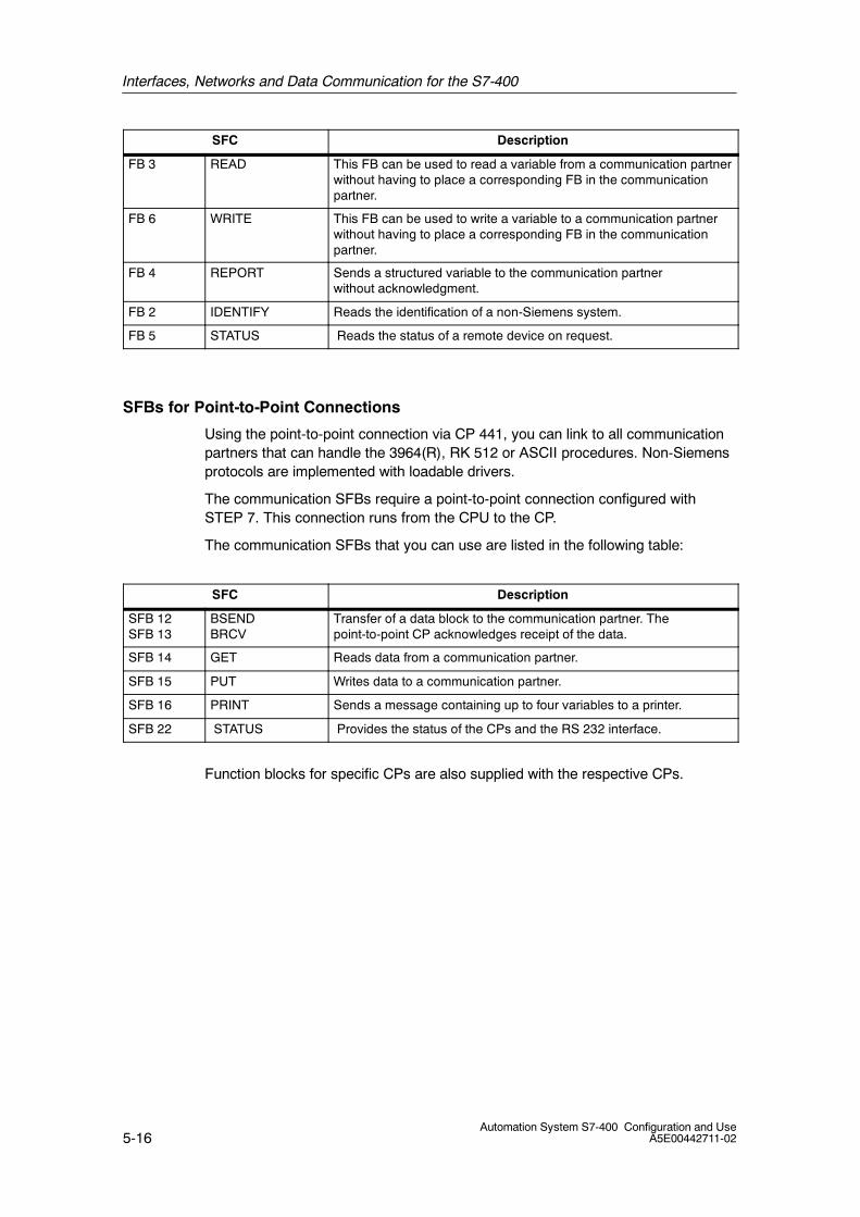
Interfaces, Networks and Data Communication for the S7-400
5-16Automation System S7-400 Configuration and Use
A5E00442711-02
SFC Description
FB 3 READ This FB can be used to read a variable from a communication partnerwithout having to place a corresponding FB in the communicationpartner.
FB 6 WRITE This FB can be used to write a variable to a communication partnerwithout having to place a corresponding FB in the communicationpartner.
FB 4 REPORT Sends a structured variable to the communication partnerwithout acknowledgment.
FB 2 IDENTIFY Reads the identification of a non-Siemens system.
FB 5 STATUS Reads the status of a remote device on request.
SFBs for Point-to-Point Connections
Using the point-to-point connection via CP 441, you can link to all communicationpartners that can handle the 3964(R), RK 512 or ASCII procedures. Non-Siemensprotocols are implemented with loadable drivers.
The communication SFBs require a point-to-point connection configured withSTEP 7. This connection runs from the CPU to the CP.
The communication SFBs that you can use are listed in the following table:
SFC Description
SFB 12SFB 13
BSENDBRCV
Transfer of a data block to the communication partner. Thepoint-to-point CP acknowledges receipt of the data.
SFB 14 GET Reads data from a communication partner.
SFB 15 PUT Writes data to a communication partner.
SFB 16 PRINT Sends a message containing up to four variables to a printer.
SFB 22 STATUS Provides the status of the CPs and the RS 232 interface.
Function blocks for specific CPs are also supplied with the respective CPs.
6-1Automation System S7-400 Configuration and UseA5E00442711-02
Configuration Variants of the S7-400
Overview
The following information is contained in this chapter:
• The structural design of the SIMATIC S7-400.
• The most important components for the configuration of an S7-400.
• How easily you can wire and exchange modules.
• The configuration of an S7-400 in one or more racks.
• The dimensions of a variety of S7-400 configurations and the spacing betweenadjacent equipment, cabinet walls, etc.
• When the S7-400 should be grounded and ungrounded.
• The configuration resources for your S7-400 assembly.
6
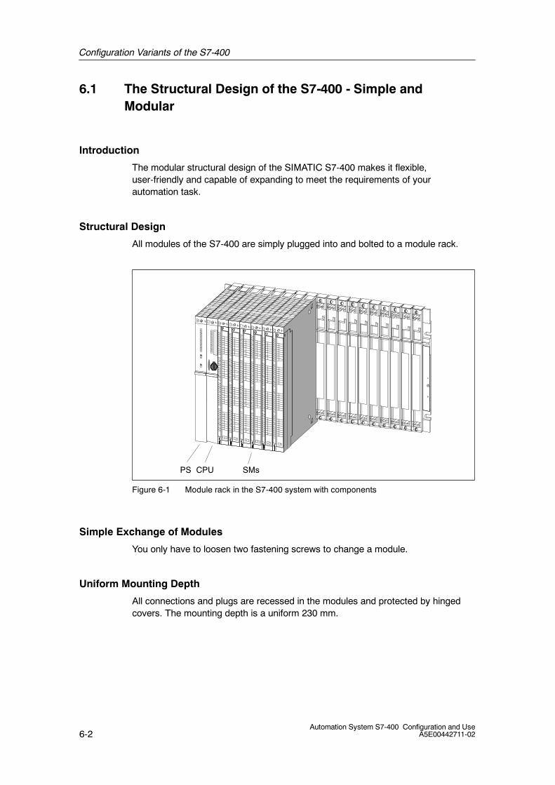
Configuration Variants of the S7-400
6-2Automation System S7-400 Configuration and Use
A5E00442711-02
6.1 The Structural Design of the S7-400 - Simple andModular
Introduction
The modular structural design of the SIMATIC S7-400 makes it flexible,user-friendly and capable of expanding to meet the requirements of yourautomation task.
Structural Design
All modules of the S7-400 are simply plugged into and bolted to a module rack.
PS CPU SMs
Figure 6-1 Module rack in the S7-400 system with components
Simple Exchange of Modules
You only have to loosen two fastening screws to change a module.
Uniform Mounting Depth
All connections and plugs are recessed in the modules and protected by hingedcovers. The mounting depth is a uniform 230 mm.

Configuration Variants of the S7-400
6-3Automation System S7-400 Configuration and UseA5E00442711-02
6.2 An Overview of S7-400 Components
Introduction
The S7-400 has a simple modular design. The most important components of anS7-400 are described in this chapter.
Component Function Image
Racks(UR = Universal Rack)(CR = Central Rack)(ER = Extension Rack)
Racks provide the mechanicaland electrical connections be-tween the S7-400 modules.
Power supply modules(PS = Power Supply)
Accessories:Back-up battery
Power supply modules convertthe mains voltage ( 120/230 VAC or 24 V DC) into the operat-ing voltage required by theS7-400, 5 V DC and 24 V DC.
CPUs(CPU = Central Processing Unit)
CPUs execute the user program;they communicate with otherCPUs and with programming de-vices.
V4.0
Memory cards Memory cards are used to storethe user program andparameters.
Interface module IF 964-DP The interface module IF 964-DPis used to connect the distributedI/O via ”PROFIBUS-DP
Signal Modules(SM = Signal Module)(digital input modules,digital output modules,analog input modulesanalog output modules)Accessories:Front connectors with three differ-ent connection systems
Signal modules adapt variousprocess signal levels to theS7-400.Signal modules form the inter-face between the PLC and theprocess.
Interface Modules(IM = Interface Module)Accessories:Cable
Terminal plug
Interface modules interconnectseparate racks of an S7-400.
Cable duct The cable duct is used lay cablesand for ventilation.

Configuration Variants of the S7-400
6-4Automation System S7-400 Configuration and Use
A5E00442711-02
Component ImageFunction
PROFIBUS bus cable PROFIBUS bus cables connectCPUs and programming devices.
Programming device cable Programming device cables con-nect a CPU with a programmingdevice.
PROFIBUS componentse.g. PROFIBUS bus terminal
PROFIBUS components con-nects an S7-400 to otherS7-400s or programming de-vices.
RS 485 repeater The RS 485 repeater boostsdata signals on bus lines andcouples bus segments.
Programming device (PG) or PCwith the STEP 7 software pack-age
STEP 7 is used to configure, as-sign parameters, program andtest the S7-400.
Fan subassembly(for special areas of application)
The fan subassembly ventilatesmodules in special applications;it can be operated with or withouta filter.

Configuration Variants of the S7-400
6-5Automation System S7-400 Configuration and UseA5E00442711-02
6.3 Connection System of S7-400 Signal Modules
Introduction
This chapter describes how you can quickly and easily establish S7-400connections to sensors and actuators.
Wiring with Front Connectors
You can use front connectors to wire the S7-400. The connection between thesignal modules of your S7-400 and the sensors and actuators of your plant isperformed in two steps:
1. Wire the front connectors, insert the cables to and from the sensors/actuatorsinto the front connectors.
2. Mount the front connectors
Figure 6-2 Front connectors and module
Configuration Variants of the S7-400
6-6Automation System S7-400 Configuration and Use
A5E00442711-02
Advantages
Wiring the S7-400 with front connectors offers you the following advantages:
• Front connectors allow you to use pre-assembled cables.
• You save time and money during assembly.
• The capability to pull and plug a completely wired front connector makesexchanging modules fast and easy.
• It makes it difficult to accidentally insert the front connectors in the wrongdirection, since they have mechanical polarization; front connectors andmodules are assigned to one another.
Fully Modular Connection
Signals can not only be connected directly to the signal modules, they can also beconnected to a remote terminal. The terminal is connected to a front connectormodule that is plugged into the signal module instead of the front connector. Thedistance between the terminal and signal module can reach up to 30 m.
Advantages
Wiring with a fully modular connection offers the following advantages:
• Fast, low-cost wiring
• High degree of wiring safety, orderly cabinet wiring
• The supply voltage for the module can be connected to the front connectormodule or to the terminal block.

Configuration Variants of the S7-400
6-7Automation System S7-400 Configuration and UseA5E00442711-02
6.4 S7-400 Assembly in a Rack
Introduction
Regardless of the S7-400 CPU you decide to use, you can equip the module rackwhere the CPU is located with up to 16 other modules in addition to the CPU andthe power supply module.
Only Two Slot Rules
You only have to observe two rules when arranging modules in a rack:
• The power supply module must be inserted in slot 1 in all racks. Redundantpower supply modules are inserted in slots 1 and 3.
• The receive IM in the expansion device must always be install at the far right.
Maximum Assembly with One Rack
Figure 6-3 shows an example of a module configuration in an S7-400 assemblyfully equipped with a power supply module, a CPU and 16 other modules.
PS CPU SMs
Figure 6-3 Rack in the S7-400 system with components
There are racks with 4, 9 or 18 slots for the S7-400.
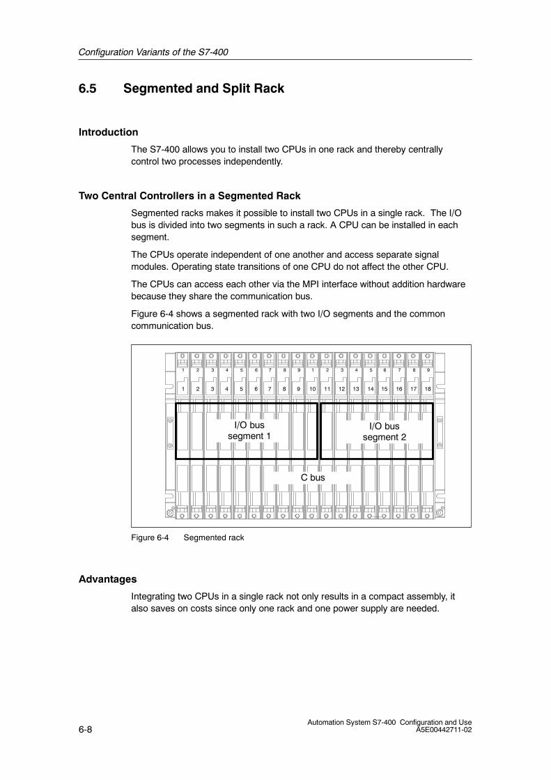
Configuration Variants of the S7-400
6-8Automation System S7-400 Configuration and Use
A5E00442711-02
6.5 Segmented and Split Rack
Introduction
The S7-400 allows you to install two CPUs in one rack and thereby centrallycontrol two processes independently.
Two Central Controllers in a Segmented Rack
Segmented racks makes it possible to install two CPUs in a single rack. The I/Obus is divided into two segments in such a rack. A CPU can be installed in eachsegment.
The CPUs operate independent of one another and access separate signalmodules. Operating state transitions of one CPU do not affect the other CPU.
The CPUs can access each other via the MPI interface without addition hardwarebecause they share the communication bus.
Figure 6-4 shows a segmented rack with two I/O segments and the commoncommunication bus.
1 2 3 4 5 6 7 8 9 1 2 3 4 5 6 7 8 9
1 2 3 4 5 6 7 8 9 10 11 12 13 14 15 16 17 18
C bus
I/O bussegment 2
I/O bussegment 1
Figure 6-4 Segmented rack
Advantages
Integrating two CPUs in a single rack not only results in a compact assembly, italso saves on costs since only one rack and one power supply are needed.

Configuration Variants of the S7-400
6-9Automation System S7-400 Configuration and UseA5E00442711-02
Two CPUs in a Split Rack
With split racks, the I/O bus and communication bus are divided into twosegments. A CPU can be installed in each segment.
Functionally, a split rack represents two electrically isolated racks on the samemounting rail.
Figure 6-5 shows a configuration of a split rack with 2x9 slots.
1 2 3 4 5 6 7 8 9 1 2 3 4 5 6 7 8 9
Device I Device II
Figure 6-5 Split rack
Advantages
Split racks are usually used for compact redundant S7-400H systems (two devicesor systems in a single rack).
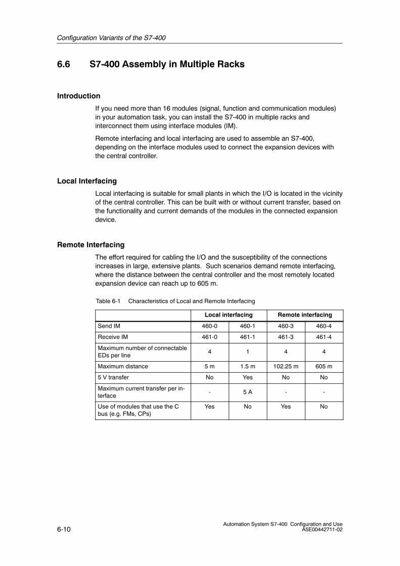
Configuration Variants of the S7-400
6-10Automation System S7-400 Configuration and Use
A5E00442711-02
6.6 S7-400 Assembly in Multiple Racks
Introduction
If you need more than 16 modules (signal, function and communication modules)in your automation task, you can install the S7-400 in multiple racks andinterconnect them using interface modules (IM).
Remote interfacing and local interfacing are used to assemble an S7-400,depending on the interface modules used to connect the expansion devices withthe central controller.
Local Interfacing
Local interfacing is suitable for small plants in which the I/O is located in the vicinityof the central controller. This can be built with or without current transfer, based onthe functionality and current demands of the modules in the connected expansiondevice.
Remote Interfacing
The effort required for cabling the I/O and the susceptibility of the connectionsincreases in large, extensive plants. Such scenarios demand remote interfacing,where the distance between the central controller and the most remotely locatedexpansion device can reach up to 605 m.
Table 6-1 Characteristics of Local and Remote Interfacing
Local interfacing Remote interfacing
Send IM 460-0 460-1 460-3 460-4
Receive IM 461-0 461-1 461-3 461-4
Maximum number of connectableEDs per line
4 1 4 4
Maximum distance 5 m 1.5 m 102.25 m 605 m
5 V transfer No Yes No No
Maximum current transfer per in-terface
- 5 A - -
Use of modules that use the Cbus (e.g. FMs, CPs)
Yes No Yes No

Configuration Variants of the S7-400
6-11Automation System S7-400 Configuration and UseA5E00442711-02
Interfacing Rules
Interface modules are divided into send IMs and receive IMs A send IM sendssignals to the connected expansion device, the corresponding receive IM receivesand forwards the signals. The following rules apply to connecting interfacemodules:
• The send IM must always be located in the central controller.
• You can connect up to four receive IM to one send IM.
• Up to six send IMs can be installed in the central controller.
Maximum of 22 Racks
Interfacing with send and receive IMs, you can connect up to 21 expansion devicesto a central controller.
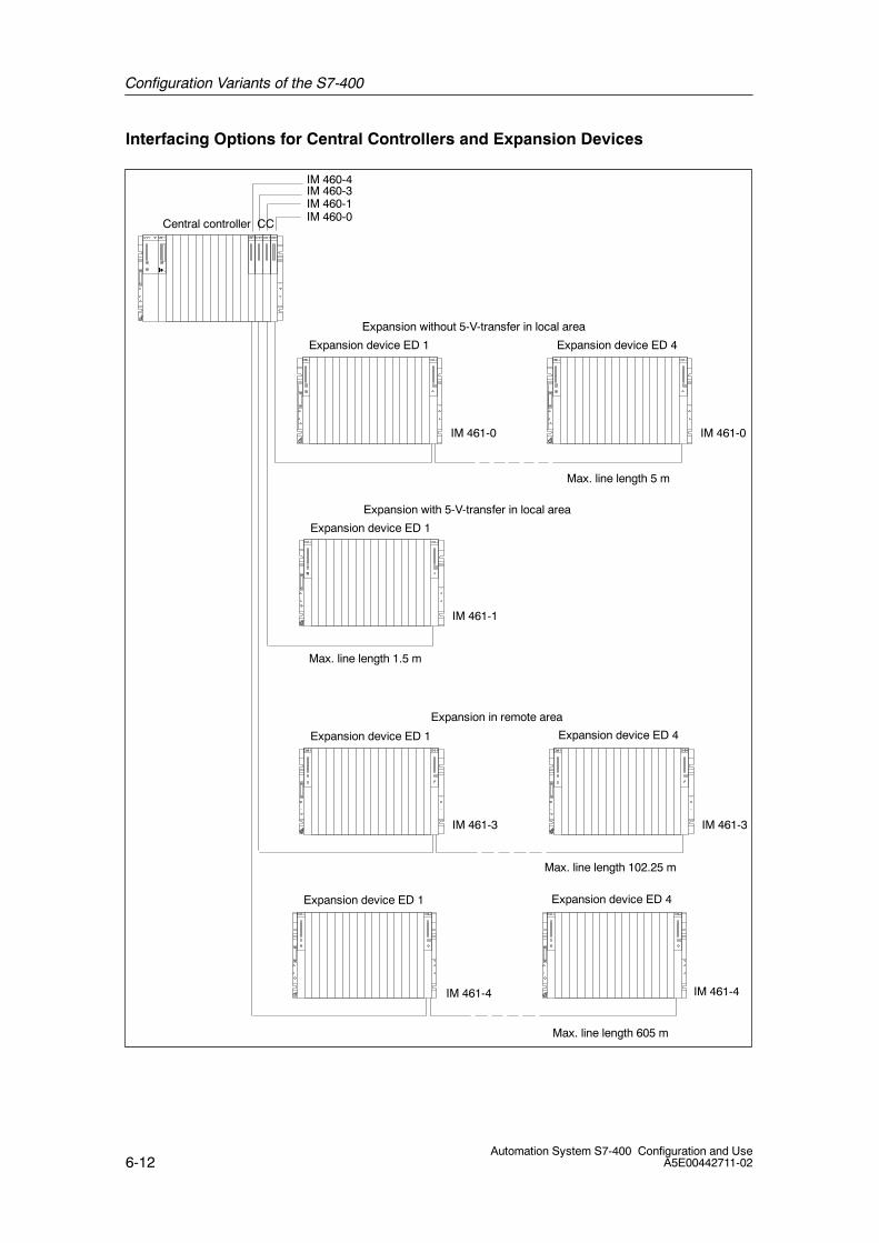
Configuration Variants of the S7-400
6-12Automation System S7-400 Configuration and Use
A5E00442711-02
Interfacing Options for Central Controllers and Expansion Devices
Central controller CC
Expansion device ED 1 Expansion device ED 4
Expansion device ED 1
Expansion device ED 1 Expansion device ED 4
Expansion without 5-V-transfer in local area
Expansion with 5-V-transfer in local area
Expansion in remote area
IM 460-0IM 460-1IM 460-3
Max. line length 102.25 m
Max. line length 1.5 m
IM 461-0 IM 461-0
IM 461-1
IM 461-3 IM 461-3
IM 460-4
Expansion device ED 1 Expansion device ED 4
Max. line length 605 m
IM 461-4 IM 461-4
Max. line length 5 m
Configuration Variants of the S7-400
6-13Automation System S7-400 Configuration and UseA5E00442711-02
6.7 Mounting Dimensions of an S7-400 Assembly
Introduction
This chapter describes the varying mounting dimensions of an S7-400 assembly.
Mounting height
The mounting height of an S7-400 assembly is determined by the height of therack. The height of the rack is 290 mm.
Special Height
If you use a fan subassembly or a cable duct in a rack, the mounting height of therack increases by the mounting height of these components.
Mounting depth
The mounting depth of a S7-400 assembly is 227.5 mm. All connectors and plugsare recessed and are within the maximum mounting depth.
Width of an S7-400 Assembly
The width of an S7-400 assembly is determined by the width of the rack used. Themounting width is:
• 132 mm for a rack with 4 slots
• 258 mm for a rack with 9 slots
• 483 mm for a rack with 18 slots
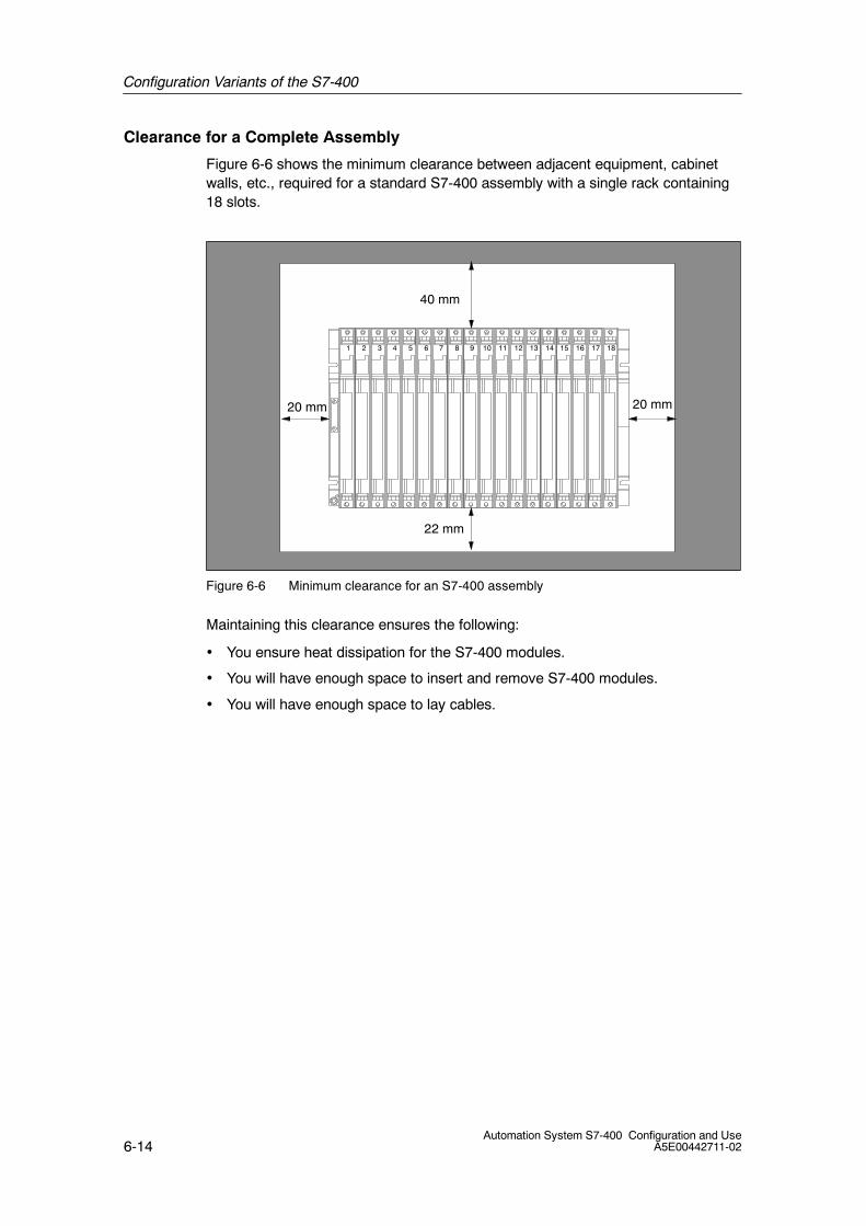
Configuration Variants of the S7-400
6-14Automation System S7-400 Configuration and Use
A5E00442711-02
Clearance for a Complete Assembly
Figure 6-6 shows the minimum clearance between adjacent equipment, cabinetwalls, etc., required for a standard S7-400 assembly with a single rack containing18 slots.
20 mm 20 mm
40 mm
22 mm
1 2 3 4 5 6 7 8 9 10 11 12 13 14 15 16 17 18
Figure 6-6 Minimum clearance for an S7-400 assembly
Maintaining this clearance ensures the following:
• You ensure heat dissipation for the S7-400 modules.
• You will have enough space to insert and remove S7-400 modules.
• You will have enough space to lay cables.
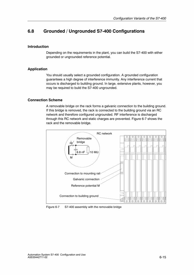
Configuration Variants of the S7-400
6-15Automation System S7-400 Configuration and UseA5E00442711-02
6.8 Grounded / Ungrounded S7-400 Configurations
Introduction
Depending on the requirements in the plant, you can build the S7-400 with eithergrounded or ungrounded reference potential.
Application
You should usually select a grounded configuration. A grounded configurationguarantees a high degree of interference immunity. Any interference current thatoccurs is discharged to building ground. In large, extensive plants, however, youmay be required to build the S7-400 ungrounded.
Connection Scheme
A removable bridge on the rack forms a galvanic connection to the building ground.If this bridge is removed, the rack is connected to the building ground via an RCnetwork and therefore configured ungrounded. RF interference is dischargedthrough this RC network and static charges are prevented. Figure 6-7 shows therack and the removable bridge.
Galvanic connection
Connection to mounting rail
Connection to building ground
RC network
M
6.8 nF 10 MΩ
Removablebridge
Reference potential M
Figure 6-7 S7-400 assembly with the removable bridge

Configuration Variants of the S7-400
6-16Automation System S7-400 Configuration and Use
A5E00442711-02
6.9 Utilities for Configuring and Assigning Parameters to anS7-400 Assembly
Introduction
One task involved in configuring a plant is assigning parameters to the hardware ofthe automation system. Increasingly complex automation tasks require more andmore effort to configure.
Configuration with STEP 7
STEP 7 provides system software to help you configure and assign parameters toyour plant. It is characterized by easy handling (selection, setting marks and fillingout dialog forms).
You can also use STEP 7 to configure modules such as CPUs and FMs. Modulesare selected from an electronic catalog. The configuration and parameterassignment data are transferred to the CPU and automatically distributed to theindividual modules at startup.
If you do not specify special values, the system automatically starts up with itsdefault settings. In other words, parameter assignment is possible but notnecessary.

7-1Automation System S7-400 Configuration and UseA5E00442711-02
Programming the S7-400
Overview
This chapter provides you with information about the system software, STEP 7.STEP 7 is used for programming, configuring, assigning parameters, testing andperforming diagnostics for the S7-400.
It also provides you with information about the programming devices and PCs inuse.
7

Programming the S7-400
7-2Automation System S7-400 Configuration and Use
A5E00442711-02
7.1 STEP 7 - the Programming Package for S7-400
Introduction
The software for programming, testing and commissioning SIMATIC S7 is calledSTEP 7. STEP 7 comes in programming packages for different ranges ofperformance.
Software User Interface
STEP 7 runs under the MS Windows 2000 Professional and MS Windows XPProfessional operating systems and is adapted to their graphic, object-orientedoperation style.
STEP 7 is based on DIN EN 6 1131-3
The STEP 7 programming software is based on the international standardDIN EN 6 1131-3. This means that STEP 7 has the same appearance as other IECprogramming languages for programmable logic controllers.
Advantage
The advantage of a programming language based on DIN EN 6 1131-3 is how littletime it takes a programmer to become acquainted with it. Programming controllersfrom different manufacturers is very similar using these programming languages.
Comprehensive Help for STEP 7
Comprehensive online help is provided to help you to a quick start and supportyour work with the various tools. It features context-sensitive instructions as well asa wide range of reference information.
Program Structure
STEP 7 offers you the option of dividing the user program into separate programsegments. There are a variety of blocks with defined properties for the variousprogram segments. The blocks can be easily tested and used over and over.
Blocks to Access the System
There are block types for structuring a program, FB (function blocks), FC(functions) and OB (organization blocks). You do not have to program everyfunction yourself. You can program communication functions, for example, usingpre-configured blocks that are available in the operating system on the CPUs.
Programming the S7-400
7-3Automation System S7-400 Configuration and UseA5E00442711-02
Program and Data Storage
Projects are used to store the data and programs which are created when you puttogether an automation solution. The data collected together in a project include:
• Configuration data on the hardware structure and parameters for modules
• Configuration data for communication in networks
• Programs for programmable modules
Data are stored in a project in object form. The objects in a project are arranged ina tree structure (project hierarchy). The display of the hierarchy in the projectwindow is similar to that of the Windows Explorer.
Program Editor
The program editor enables you to program in conformity to the IEC 1131 standardfor the S7-400 automation system. You can use both symbolic and absoluteaddressing of the operands when writing programs.
Programming Languages
• LAD (Ladder Logic) is a graphic programming language. Its syntax for theinstructions is similar to a circuit diagram. Ladder allows you to track the powerflow between power rails as it passes through various contacts, complexelements, and output coils.
• STL (Statement List) is a textual programming language similar to machinecode. If a program is written in Statement List, the individual instructionscorrespond to the steps with which the CPU executes the program. To makeprogramming easier, Statement List has been extended to include somehigh-level language constructions (such as structured data access and blockparameters).
• FBD (Function Block Diagram) is a graphic programming language and usesthe logic boxes familiar from Boolean algebra to represent the logic. Complexfunctions (for example, math functions) can be represented directly inconjunction with the logic boxes.
• SCL (Structured Control Language) is a programming language resemblingPascal used especially for programming complex algorithms and mathematicalfunctions or for task definitions from the area of data processing.
• CFC (Continuous Function Chart) enables you to accomplish technologicaltasks in completed, executable automation programs with minimal effort. Youcan insert the ready-to-use blocks from a library into a CFC chart usingdrag-and-drop, graphically interconnect them and assign parameters to them.In-depth programming knowledge is not needed.
Data Storage in the Programming Device
The programming device stores the data for all S7-400 components. This meansyou only have to enter your data once and then it is available for configuration,programming and for operator control and monitoring functions.
Programming the S7-400
7-4Automation System S7-400 Configuration and Use
A5E00442711-02
7.2 Programming Devices for SIMATIC S7
Introduction
A programming device (PG) is a special industrial-grade personal computer with acompact design. It is fully equipped for programming SIMATIC automationsystems.
Characteristics of the Programming Devices
A PG or PC with the meeting the following requirements is needed to workeffectively with STEP 7:
PG/PC Properties Recommendation
Operating system and user interface Microsoft Windows 2000, Windows XP
Processor Pentium
• for Windows 2000 P 600
• for Windows XP P 600
Main memory at least 256 MB
512 MB recommended
Free disk space 300 to 600 MB, depending on scope of theinstallation
Graphics XGA 1024x768,16-bit color depth
Color monitor, keyboard and mouse Windows-compatible
If you have large STEP 7 projects or HW configurations, you should use aprogramming device or a PC with processing power that corresponds with what iscurrently available on the market.
Programming the S7-400
7-5Automation System S7-400 Configuration and UseA5E00442711-02
7.3 Convenient Testing and Diagnostic Options
Testing Functions
SIMATIC S7 provides convenient testing functions for testing the user program.You can monitor both the block status and the variable status.
The test functions allow you to perform quick commissioning and easily locateerrors.
Information Functions
High-performance information functions are provided in addition to the testingfunctions. The CPUs provide information about:
• Type and version of the CPU
• Their ”performance specifications”(e.g. type and number of operands)
• Available and used memory capacity
• Current status of the automation system(e.g. module(s) ”Ok”, configuration of the automation system, error eventsthat have occurred, chronology of the events).
Diagnostics in the User Program
You can include blocks for error handling in the user program with STEP 7.
Example: Organization blocks (OBs) for handling programming and device errors,for example, for calling unloaded blocks, for unacknowledged modules or forbattery failure.
Not only CPUs can trigger an OB call, diagnostic-capable modules can also dothis. These modules generate a diagnostic interrupt that results in the call of anerror OB. The error OBs provide detailed information about the type, location andtime of the error.
Diagnostics with PG or OP
What must you do to have diagnostic data displayed by the display system such asa programming device or operator panel? The answer in the easiest case isnothing! For example, when the CPU is set to STOP by an error, it automaticallysends the most recent diagnostic message to the connected display system,providing you with immediate feedback about what is happening in the automationsystem.
Every diagnostic event, even one that does not result in a CPU STOP, can beevaluated with the connected display system. Several options are available for anevaluation:
• Evaluation of the current status of the automation system
• Evaluation of the ”history” of diagnostic events
Programming the S7-400
7-6Automation System S7-400 Configuration and Use
A5E00442711-02
Diagnostics Buffer
A diagnostics buffer in the CPU is available for evaluating the history of diagnosticevents. The size of this diagnostics buffer depends on the type of CPU used
Example: A CPU with a diagnostics buffer for 200 diagnostic entries show the last200 diagnostics entries. New incoming diagnostic messages overwrite the ”oldest”diagnostic entries.
Advantages
The testing and diagnostic options for the S7-400 offers you the followingadvantages:
• Easy to understand because of a uniform system solution
• Less time needed for program testing and commissioning
• Fast error analysis and correction, increases plant availability
• Permits verification of prohibited and incorrect operations and manipulationsbased on the entries in the diagnostics buffer (e.g. STOP SWITCH ACTIVATED10/20/04 23:59; module removed ...)

8-1Automation System S7-400 Configuration and UseA5E00442711-02
Operator Control and Monitoring with theS7-400
Overview
This chapter provides you with information about the operator control andmonitoring devices for S7-400 and their easy and convenient operation.
8

Operator Control and Monitoring with the S7-400
8-2Automation System S7-400 Configuration and Use
A5E00442711-02
8.1 Convenient Operator Control and Monitoring of ComplexProcesses with SIMATIC HMI
Introduction
The more complex automation processes are, the more important a process-based”human-machine interface” becomes. SIMATIC HMI is a mature system forconvenient process control and monitoring.
Touch Panels and Operator Panels
Operator panels (OPs) and touch panels (TPs) enable fast intervention on themachine. They are usually used at a station or by service personnel. You can usethem to change parameters for specific machines alphanumerically andgraphically.
You can enter data on the touch panels using a touch-sensitive display and onmembrane keyboards on an operator panel.
Mobile Panel
The portable HMI devices allow you to perform operator control and monitoring atthe actual location where something is occurring with direct access and visiblecontact to the process. It offers simple and safe hot pulling and plugging, and cantherefore be used flexible at machines or plants.
Win CC flexible
Win CC flexible is the engineering software for all HMI devices. It allowscomprehensive configuration of every HMI device and even PC-based visualizationstations. Once a configuration is created, you can use it anywhere in the SIMATICHMI product range.
WinCC flexible is available in a variety of versions based on price and performanceand tailored to the individual classes of HMI devices.

9-1Automation System S7-400 Configuration and UseA5E00442711-02
Standards, Certificates and Approvals
In this Chapter
This chapter describes the standards, certificates and approvals maintained andfulfilled by the modules and components of the S7-400 automation system.
Warning
This chapter describes the standards, certificates and approvals. You will find thecurrent approvals on the rating plate of the respective products.
9
Standards, Certificates and Approvals
9-2Automation System S7-400 Configuration and Use
A5E00442711-02
9.1 Standards, Certificates and Approvals
!Warning
Open equipment
Death, serious injury, or considerable damage to property may occur.
Modules of the S7 400 are open equipment. This means you can only install theS7-400 in enclosures or cabinets.
The enclosures or cabinets may only be access by a key or with a tool and only byauthorized personnel.
IEC 61131-2
The S7-400 automation system fulfills the requirements and criteria of the IEC61131-2 standard (Programmable Logic Controllers, part 2: EquipmentRequirements and Verifications).
CE Label
Our products fulfill the requirements and protection goals of the following ECguidelines and matches the harmonized European standards (EN)that have been published for the programmable logic controllers in the officialjournals of the European communities:
• 73/23/EEC ”Electrical Equipment for Use within Fixed Voltage Ranges”(Low-Voltage Directive)
• 89/336/EEC ”Electromagnetic Compatibility” (EMC Directive)
• 94/9/EC ”Equipment and protective systems intended for use in potentiallyexplosive atmospheres” (Explosion Protection Directive)
The EC declarations of conformity are kept available for the responsible authoritiesat the following address:
Siemens AktiengesellschaftAutomation and DrivesA&D AS RD STP.O. Box 1963D-92209 AmbergFederal Republic of Germany
You can find this for downloading at the Internet customer support site under theheading of ”Conformity Declarations”.
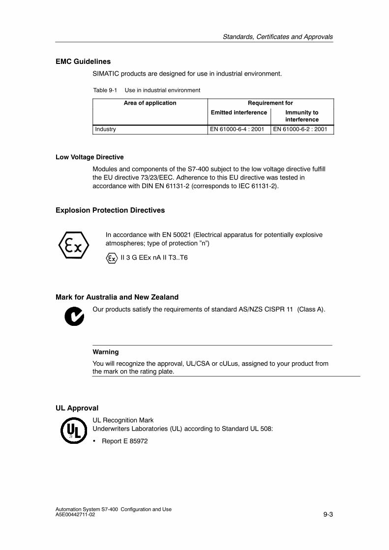
Standards, Certificates and Approvals
9-3Automation System S7-400 Configuration and UseA5E00442711-02
EMC Guidelines
SIMATIC products are designed for use in industrial environment.
Table 9-1 Use in industrial environment
Area of application Requirement for
Emitted interference Immunity tointerference
Industry EN 61000-6-4 : 2001 EN 61000-6-2 : 2001
Low Voltage Directive
Modules and components of the S7-400 subject to the low voltage directive fulfillthe EU directive 73/23/EEC. Adherence to this EU directive was tested inaccordance with DIN EN 61131-2 (corresponds to IEC 61131-2).
Explosion Protection Directives
In accordance with EN 50021 (Electrical apparatus for potentially explosiveatmospheres; type of protection ”n”)
II 3 G EEx nA II T3..T6
Mark for Australia and New Zealand
Our products satisfy the requirements of standard AS/NZS CISPR 11 (Class A).
Warning
You will recognize the approval, UL/CSA or cULus, assigned to your product fromthe mark on the rating plate.
UL Approval
UL Recognition MarkUnderwriters Laboratories (UL) according to Standard UL 508:
• Report E 85972
Standards, Certificates and Approvals
9-4Automation System S7-400 Configuration and Use
A5E00442711-02
CSA Approval
CSA Certification MarkCanadian Standard Association (CSA) according to Standard C 22.2 No. 142:
• Certification Record 212191-0-000
or
cULus Approval
Underwriters Laboratories Inc. according to
S UL 508 (Industrial Control Equipment)
S CSA C22.2 No. 142 (Process Control Equipment)
or cULus Approval, Hazardous Location
CULUS Listed 7RA9 INT. CONT. EQ. FOR HAZ. LOC.
Underwriters Laboratories Inc. according to
S UL 508 (Industrial Control Equipment)
S CSA C22.2 No. 142 (Process Control Equipment)
S UL 1604 (Hazardous Location)
S CSA-213 (Hazardous Location)
APPROVED for Use in
S Cl. 1, Div. 2, GP. A, B, C, D T4A
S Cl. 1, Zone 2, GP. IIC T4
Please read the notes below.
HAZ. LOC.
Standards, Certificates and Approvals
9-5Automation System S7-400 Configuration and UseA5E00442711-02
or cULus Approvals, Hazardous Location for Relay Modules
CULUS Listed 7RA9 INT. CONT. EQ. FOR HAZ. LOC.
Underwriters Laboratories Inc. according to
S UL 508 (Industrial Control Equipment)
S CSA C22.2 No. 142 (Process Control Equipment)
S UL 1604 (Hazardous Location)
S CSA-213 (Hazardous Location)
APPROVED for Use in
S Cl. 1, Div. 2, GP. A, B, C, D T4A
S Cl. 1, Zone 2, AEx nC IIC T4
S Cl. 1, Zone 2, Ex nC IIC T4
Please read the notes below.
Warning
This plant has to be mounted according to the NEC (National Electric Code)stipulations.
When used in environments according to class I, division 2 (see above) , S7-400must be mounted in an enclosure that corresponds to at least IP54 according toEN 60529.
FM Approval
Factory Mutual Approval Standard Class Number 3611, Class I, Division 2, GroupA, B, C, D.
Temperature class: T4 at 60 °C ambient temperature
!Warning
Personal injury and property damage can occur.
In hazardous areas, personal injury or property damage can result if you create orbreak an electrical circuit during operation of an S7-400 (for example, by means ofplug-in connections, fuses, switches).
Do not create or break live electric circuits unless you are certain there is nodanger of explosion.
If you use S7-400 under FM conditions, it has to be mounted in an enclosure,which at least corresponds to IP54 in accordance with EN 60529.
HAZ. LOC.

Standards, Certificates and Approvals
9-6Automation System S7-400 Configuration and Use
A5E00442711-02
Marine Type Approval
Classification organizations:
• ABS (American Bureau of Shipping)
• BV (Bureau Veritas)
• DNV (Det Norske Veritas)
• GL (Germanischer Lloyd)
• LRS (Lloyds Register of Shipping)
• Class NK (Nippon Kaiji Kyokai)
Safety Requirements for Installation
The S7-400 automation systems are “open type” equipment according to theIEC 61131-2 standard and therefore adhere to the EU directive 73/23/EEC“Low-Voltage Directive” and are UL/CSA certified as such.
To fulfill requirements for safe operation with regard to mechanical stability, flameretardence, stability, and shock-hazard protection, the following alternative types ofinstallation are specified:
• Installation in a suitable cabinet
• Installation in a suitable enclosure
• Installation in a suitably equipped, enclosed operating area
10-1Automation System S7-400 Configuration and UseA5E00442711-02
Further Information
Documentation Landscape
This appendix presents you with the documentation landscape for SIMATIC S7.The following types of documentation are available, addressing a variety of goalsand user groups:
• Catalogs
• System-based brochures
• Product-based manuals
Catalogs
Our catalogs include information and order information for the hardware andsoftware components that you can use with SIMATIC S7.
Manuals
Our manual are based on products and provide you with comprehensiveinformation and the explicit instructions you need to solve your automation taskusing SIMATIC S7.
Getting Started
Getting Started manuals provide step-by-step instructions for initial commissioningof specific products. A Getting Started manual allows you to become acquaintedwith a product using a concrete example of an application.
Documentation in the InternetThe guide to the collection of technical documentation for individual SIMATICproducts and systems is available at:
http://www2.automation.siemens.com/simatic/portal/html_00/techdoku.htm
You can download manuals there free of charge.
The online catalog and the online ordering system is located at:
http://www2.automation.siemens.com/simatic/controller/html_00/ecommerce/ecommerce.htm
10

Further Information
10-2Automation System S7-400 Configuration and Use
A5E00442711-02
Manual Collection
All SIMATIC manuals are available in electronic form in the SIMATIC ManualCollection. It provides fast access to information for commissioning and servicing,and for office use where you can save the space often required by paperdocuments.
The SIMATIC Manual Collection includes the electronic form of the manuals for thefollowing product ranges:
• LOGO!
• SIMADYN
• SIMATIC Bus Components
• SIMATIC C7
• SIMATIC Distributed I/O
• SIMATIC HMI
• SIMATIC M7
• SIMATIC Machine Vision
• SIMATIC NET
• SIMATIC PC-Based Automation
• SIMATIC PCS 7
• SIMATIC PG/PC
• SIMATIC S7
• SIMATIC Software
• SIMATIC TDC
The SIMATIC Manual Collection in five languages consists of the followingcomponents:
• 5 CD-ROMs with the SIMATIC Manual Collection without SIMATIC HMI
• 2 CD-ROMs with the SIMATIC HMI Manual Collection
• 1 DVD with both manual collections in all five languages
The collection is update several time a year.
Courses
We offer a number of courses to help you become familiar with the SIMATIC S7automation system. Please contact your regional training center or our centraltraining center in D 90327 Nuremberg, Germany for details:
Tel.: +49 (911) 895-3200.
Internet: http://www.sitrain.com

Index-1Automation System S7-400 Configuration and UseA5E00442711-02
Index
A
Address ranges, 3-4Analog module, 3-2Analog modules, Performance characteristics,
3-8Approval
CSA, 9-4UL, 9-3
Availability, 2-13
BBuffering, 2-9
CC-bus:, 6-9Cam controlling, 4-7CE-Label, 9-2Certifications and approvals, 9-2CFC, 7-3CiR, 2-11Clock Synchronicity, 2-12Communication functions, 5-12Communication modules, 1-7Configuration Changes, 2-11Configuration variants, 1-8Configuration with STEP 7, 6-16Connection, Fully modular, 6-6Connection system, 6-5Continuous Function Chart, 7-3Controlling, 4-3, 4-9Counting, 4-3CP 440, 5-11CP 441--2, 5-11CP 443--1 Advanced, 5-9CP441--1, 5-11CPU, 1-6, 6-3CPU 416F, 2-18CPUs, Performance characteristics, 2-6CSA, Approval, 9-4cULus Approval, 9-4
Hazardous Location, 9-4, 9-5
DData storage, 7-3Diagnostics, 3-5, 7-5Diagnostics Buffer, 2-5Diagnostics buffer, 7-6Digital module, 3-2Digital modules, Performance characteristics,
3-6DIN V 19250/DIN V VDE 0801, 2-18Displays, 2-3Distributed I/O, 5-7Distributed safety, 2-18Documentation package, ivDP master, 5-6DP slave, 5-6
EEasy Motion Control, 4-13EMC-Guidelines, 9-3EN 6 1131--3, 7-2EN 954--1, 2-18Error displays, 2-3EXM 438--1, 4-12EXM 448, 4-12EXM 448--2, 4-12Expansion, 1-4Explosion Protection Directives, 9-3
FFail--safe user program, 2-21Fault--tolerant connections, 2-14FBD, 7-3FM, Approval, 9-5FM 450--1
Counter functions, 4-5Performance characteristics, 4-5
FM 451Functions:, 4-6Performance characteristics, 4-6
FM 452Functions:, 4-7Performance characteristics, 4-7

Index
Index-2Automation System S7-400 Configuration and Use
A5E00442711-02
FM 453Functions:, 4-8Performance characteristics, 4-8
FM 455Functions:, 4-9Performance characteristics, 4-10
FM 458--1 DPConfiguration, 4-11Functions, 4-11Performance characteristics, 4-11
Frequency measurement, 4-3Front connectors, 6-5Fully modular connection , 6-6Function diagram, 7-3Function Modules, Access, 4-3Function modules, 1-7, 4-3
GGrounded configuration, 6-15Grounded reference potential, 6-15Guide, to the manual, iv
II/O, 2-3
redundant, 2-15Single--channel, one--way, 2-15Single--channel, switched, 2-15
I/O area, 3-4I/O-bus:, 6-9I/O interface
PROFIBUS DP, 5-6PROFINET IO, 5-8
IE PB Link PN IO, 5-9IEC 61131-2, 1-2, 9-2IEC 61508, 2-18Information functions, 7-5Instruction Set, 2-4Interface Modules, 1-7IO controller:, 5-9IO device, 5-9
Configuration, 5-9IO supervisor, 5-9
LLAD, 7-3Ladder Logic, 7-3Linking, 2-14Loading memory, 2-9Local interfacing, 6-10Low Voltage Directive, 9-3
MManual, Purpose, iiiManual package, ivMarine type approval, 9-6Mobile panel, 8-2Modular PID Control, 4-14Mounting depth, 6-13Mounting height, 6-13MPI interface, 5-3MPI/DP Interface, 2-3Multicomputing, 2-10
OOpen equipment, 9-2Operating Mode Switch, 2-2Operator panel, 8-2
PPartial connection, active, 2-14PASCAL, 7-3Password, 2-3Performance Characteristics, 1-5Performance characteristics of the analog
modules, 3-8Performance Characteristics of the CPUs, 2-6Performance characteristics of the digital
modules, 3-6PID Self--Tuner, 4-15PID Temperature Control, 4-15PMC , 4-16Point--to--point connections, 5-16Positioning, 4-3
Closed--loop, 4-8, 4-11Controlled, 4-6
Power Supply, 6-3Power supply, 1-7Process interrupt, 3-5PROFIBUS DP
Characteristics, 5-7Structure, 5-6, 5-8
Profibus DP Interface, 2-3PROFINET IO
Characteristics, 5-9Structure, 5-9, 5-10
Program Editor , 7-3Program storage, 7-3Programming device, 7-4
Characteristics, 7-4Protection level, 2-3
Index
Index-3Automation System S7-400 Configuration and UseA5E00442711-02
RRacks, 1-7, 6-3, 6-7
Segmented, 6-8Split, 6-9
Redundant I/O, 2-15Reference potential, 6-15Remote interfacing, 6-10Required level of knowledge, iiiRetention, 2-9RS 232C module, 5-11RS 422/485 module, 5-11
SS5--compatible communication, 5-15S7 basic communication, 5-12, 5-13S7 communication, 5-13S7--400F, 2-18S7--400H, 2-13Safety functions, 2-18, 2-20SCL, 7-3Scope, of the manual, iiiSelf--test, 2-15Signal module, 3-2
Address range, 3-4Addressing, 3-4I/O area, 3-4Parameter assignment, 3-3
Signal modules, 1-7Signal modules (SM), 6-3Single operation, 2-16Single--channel, one--way I/O, 2-15Single--channel, switched I/O, 2-15Standard communication, 5-15Standard PID Control, 4-14
Standards, 9-2Statement List, 7-3Status displays, 2-3STEP 7, 7-2STL, 7-3Structural design, 6-2Structure
Grounded, 6-15Ungrounded, 6-15
Structured Control Language, 7-3Synchronization modules, 2-13Synchronizing, 2-14System data area, 3-4System memory, 2-9
TTCP/IP communication, 5-15Testing functions, 7-5Totally Integrated Automation, 1-2Touch panel, 8-2TTY module, 5-11
UUL, Approval, 9-3Ungrounded configuration, 6-15Ungrounded reference potential, 6-15User memory, 2-9
WWin CC flexible, 8-2Wiring, 6-5

Index
Index-4Automation System S7-400 Configuration and Use
A5E00442711-02