automatic velocity estimation of targets in dynamic stereo · automatic velocity estimation of...
TRANSCRIPT

AUTOMATIC VELOCITY ESTIMATION OF TARGETS IN DYNAMIC STEREO
Norbert Scherer, Michael Kirchhof, Rolf Schafer
FGAN-FOM Research Institute for Optronics and Pattern Recognition, Gutleuthausstr. 1, 76275 Ettlingen, Germany
KEY WORDS: camera calibration, homography, parameter estimation, position estimation, velocity estimation, structure from motion
ABSTRACT:
In this paper we focus on a stereo system consisting of one stationary and one moving platform. The stationary platform detectsmotions and gives cues to the moving platform. When an object is in the field of view of both sensors the object’s position, velocity,and acceleration are estimated from stereo. To prove the results a second stationary sensor platform is available to compute a referencefrom traditional stereo. We describe investigations about the accuracy and reliability concerning the automatic velocity estimation oftargets in image sequences of multi-ocular systems with emphasis on moving sensor platforms. In order to make the assessment morecomprehensible, we discuss a stereo-system consisting of one stationary and one moving platform. Therefore in this context dynamicstereo means that the stereo basis and relative orientation are varying within the image sequence.We present image sequences originating from different sensors at different positions including one moving sensor that were recordedduring the same time span. Since all-day capability is required for warning systems predominantly infrared (IR) sensors were employed.We took image sequences of scenarios with one or more vehicles. The vehicles moved with typical velocities in natural surrounding.Their distances to the sensors was in the close range. The trajectories of all sensors and vehicles were registered with GPS-recorders toobtain ground-truth data.
1 INTRODUCTION
Modern automatic surveillance and warning systems need to en-sure the safety of high value targets. To achieve results that guar-antee adequate protection against different attacks high qualityclassifications of threats are essential. Incorporating the move-ment patterns of active objects appearing in the field of view ofthe surveillance system into the analysis of potential threats im-proves the reliability of the classification results. This is true evenmore, if the information about the movement of the objects is ofhigh quality. The required high quality information could be ob-tained by a reconstruction of the trajectory of the objects in timeand space, which can be done with multi-ocular stereo vision.Furthermore, a more precise definition of the threat is obtained,if the accuracy of the reconstructed trajectory allows the deriva-tion of the three-dimensional velocity and acceleration of eachobject. Especially for objects moving directly towards the sensor,the three-dimensional position, velocity or even acceleration ofthe object are of highest interest, since they result in more robustfeatures than shape, size, texture or intensity for the analysis ofthe threat. Since also moving objects need protection, e.g., con-voys of vehicles, the necessity to discuss a moving sensor plat-form arises. In order to make the assessment more comprehensi-ble, we discuss a stereo-system consisting of one stationary andone moving platform.
The analysis starts with detection and tracking of objects in eachindividual image sequence. Additionally the trajectory of themoving sensor is estimated by Structure-From-Motion methods(Hartley and Zisserman, 2000), (Kirchhof and Stilla, 2006). Theaccuracy of the trajectory and relative orientation is improved bysliding bundle adjustment over up to 100 subsequent frames. Theresulting trajectory is then matched with the corresponding GPS-track of the vehicle carrying the moving sensor. This ensures thatall cameras can now be described in the same coordinate sys-tem. Afterwards the correspondence problem is solved and thethree-dimensional trajectories and velocities of the observed ob-jects are reconstructed (Scherer and Gabler, 2004). The accuracyof the reconstructed trajectories in space and time is assessed by
comparison to the recorded GPS-data. Furthermore to analyzepossible performance degradations arising from the movement ofsensors, we compare the results of the moving stereo system withthe results of a stereo system consisting of two stationary sensors.The solution to the correspondence problem and the trajectoryand velocity estimation of the observed object is identical for thestationary and the dynamic case.
1.1 Related Work
Typical approaches for the estimation of the trajectory and ve-locity of moving objects assume that the objects move on an ob-served plane. In this case a monocular image sequence is suffi-cient to determine the trajectory and velocity of a moving object.One typical example may be (Reinartz et al., 2006). Reinartzet al. compute a georeferenced image sequence which allowsto compute the position and velocity directly from image dis-placements. Nister presented quite different work about dynamicstereo (Nister et al., 2004) introducing a system of a stereo cam-era mounted on a vehicle. The advantage of this system is thatthe stereo basis and relative orientation remain constant over thesequence although the sensors are moving. The approach pre-sented here is based on (Scherer and Gabler, 2004) where therange and velocity of objects at long ranges were computed fromtriangulation. Caused by the long range application the contri-bution focuses on discretization effects in the range and velocityestimation. For such applications the relative rotations betweenthe sensors is very important while the relative positioning errorcan be very large without effecting the results. Therefore posi-tioning the sensors with GPS was sufficient in that work.
Our application is in close range where the relative positioningerror induces very large disparities. Therefore the registration ofthe stationary sensor positions was improved by adjustments overmany GPS-measurements supported by distance measurements.Additionally the registration of the orientation was done by thecomparison of the sensor’s view with the view of a virtual cameracomputed from laser measurements taken from a helicopter.
In: Stilla U et al (Eds) PIA07. International Archives of Photogrammetry, Remote Sensing and Spatial Information Sciences, 36 (3/W49B)¯¯¯¯¯¯¯¯¯¯¯¯¯¯¯¯¯¯¯¯¯¯¯¯¯¯¯¯¯¯¯¯¯¯¯¯¯¯¯¯¯¯¯¯¯¯¯¯¯¯¯¯¯¯¯¯¯¯¯¯¯¯¯¯¯¯¯¯¯¯¯¯¯¯¯¯¯¯¯¯¯¯¯¯¯¯¯¯¯¯¯¯¯¯¯¯¯¯¯¯¯¯¯¯¯¯¯¯¯
151

1.2 Notation
We describe experiments in which we employed different vehi-cles (V1, V2 and V3). The vehicles V1 and V2 where monitoredwith three different cameras (C1, C2 and CV ). Cameras C1 andC2 were stationary, whereas camera CV was mounted on top ofvehicle V3, which followed V1 and V2. V1 was driving in frontof V2. The positions of the vehicles were tracked with GlobalPositioning Systems (GPS). The GPS-receivers are described bythe letter G. The connection to the vehicle, which’s position ismeasured, is established by the use of an index that correspondsto the vehicle, i. e. the GPS-system in the vehicle V1 is depictedby G1. To obtain further ground-truth information we used theinformation of a GPS-system GH mounted on a helicopter VH ,which performed laser measurements of the area in which ourexperiments took place.
2 DATA ACQUISITION
The data described in this paper had been recorded during a mea-surement campaign realized by the authors and other members ofFGAN-FOM. The campaign took place at the end of September2006.
Three infrared cameras (C1, C2 and CV ) were used as imagingsensors. The cameras C1 and C2 were from AIM INFRAROT-MODULE. Camera CV was from FLIR Systems. The technicaldetails of the cameras are summarized in table 1.
Ground truth data were recorded using the Global PositioningSystem (GPS). The vehicles V1 and V2 employed portable GPS-systems GPSMAP 76CSx (G1 and G2). V3, which carried theCamera CV , was equipped with a GPS-mouse system (G3). Theportable GPS-systems were also used to determine the positionsof the stationary cameras C1 and C2 and some additional outstand-ing points in the terrain.
Furthermore the terrain was scanned with a Riegl LMS Q650laser scanner, which was mounted on a Helicopter (VH ) of typeBell UH-1D. The scans produced several overlapping stripescontaining height profiles of the terrain. VH was equipped withan Inertial Measurement Unit (IMU) and a GPS-antenna (GH ).The signals from both sensors were processed by a special com-puter in such a way that position, orientation and acceleration ofthe helicopter are known during the data acquisition phase. Fur-ther details of the helicopter equipment can be found in (Hebel etal., 2006).
3 TRIANGULATION AND VELOCITY ESTIMATION
We are now going to describe our general approach. First weshow the general procedure of obtaining a three-dimensionaltrack for the case of two stationary cameras. Second the neces-sary modifications to expand the approach to the case of movingsensors are depicted.
Generally the approach is divided into two steps. In the first stepthe image sequences of each sensor are processed separately. The
Camera FOV Spectrum No. of PixelsC1 17.5◦ × 13.3◦ 4.4 - 5.2 µm 640 × 480C2 18.7◦ × 14.1◦ 2.0 - 5.3 µm 384 × 288CV 20.0◦ × 15.0◦ 3.0 - 5.0 µm 320 × 256
Table 1: Technical Data of the used IR-cameras.
results of this step are then used as input to the second step. Thesecond step combines the results of the analysis of the two imagesequences and constitutes the desired three-dimensional track ofthe object of interest.
3.1 Stationary Case
The first step of creating a three-dimensional track applies an In-frared Search and Track (IRST) algorithm to each of the imagesequences. This algorithm starts with pre-processing the imagesto correct for sensor specific inhomogeneities. Afterwards the im-age sequences are integrated to increase the signal-to-noise-ratio.In the resulting sequences point like objects are tracked, so thattwo-dimensional tracks of these objects are created in each imagesequence.
Figures 1, 2 and 3 show examples of the ’point-like objects’ asseen from the cameras C1, C2 and CV . The images have beentaken at the same time. The point-like objects found by the appli-cation of the IRST-algorithm are marked with rectangles. Pleasenotice that not all of the marked points in one image must have acorresponding mark in any of the other two images. On the otherhand the blue rectangle in each image marks a point that has cor-respondences in the other images. That point belongs to the backof vehicle V1. An example of a two-dimensional track resultingfrom one object is given in figure 4.
The second step uses the two-dimensional tracks that havebeen created by the IRST-algorithm and reconstructs the three-dimensional trajectories of objects by combining correspondingtwo-dimensional tracks from the image sequences. For this re-construction the knowledge of the camera’s position and orien-tation are important. Further details and a theoretical discussionof the accuracy and reliability of this approach can be found in(Scherer and Gabler, 2004).
3.2 Dynamic Case
In the dynamic case one camera is moving during the observation.Therefore the second step of the analysis procedure is modified insuch a way that the possible changes of the positional information(position and orientation) of the camera are considered. Theseinformation are obtained with Structure from Motion methods asdescribed later in 4.3.
Since these methods only return relative positional informations,they have to be transformed into our reference frame by an Eu-clidean transformation. This is done by fitting the whole track ofthe moving camera CV to the whole track of the sensor carryingvehicle V3 obtained from the GPS-system G3.
Due to the variance of the positional information obtained by ourGPS-receivers a final translation of the whole track of the mov-ing camera is needed. This translation is obtained by comparingthe position of the moving camera at one point in time with theposition where it is seen in the corresponding image of one of thestationary cameras.
4 CALIBRATION AND SYNCHRONIZATION
The measurement of the velocity of vehicles requires knowledgeabout the time at which the vehicle is at a certain point. Since wewant to estimate the velocity from different cameras and comparethe results with ground-truth-data the data-streams of all sensorsneed to be ’synchronized’ not only in time but also in space.
PIA07 - Photogrammetric Image Analysis --- Munich, Germany, September 19-21, 2007¯¯¯¯¯¯¯¯¯¯¯¯¯¯¯¯¯¯¯¯¯¯¯¯¯¯¯¯¯¯¯¯¯¯¯¯¯¯¯¯¯¯¯¯¯¯¯¯¯¯¯¯¯¯¯¯¯¯¯¯¯¯¯¯¯¯¯¯¯¯¯¯¯¯¯¯¯¯¯¯¯¯¯¯¯¯¯¯¯¯¯¯¯¯¯¯¯¯¯¯¯¯¯¯¯¯¯¯¯
152

‘
Figure 1: Image from camera C1. In the center of the picture ve-hicle V1 can be seen. Vehicle V2 follows V1. The rectangles mark’objects’ for which two-dimensional tracks had been created bythe IRST-algorithm.
Figure 2: Image from Camera C2 taken at the same time as theimage shown in figure 1. Rectangles mark ’objects’ that had beenfound by the application of the IRST-algorithm.
4.1 Spatial Registration
The positions of the stationary cameras C1 and C2 were estab-lished by combing all available position measurements (GPS, po-sition information derived from the laser scans of the helicopterand some additional distance measurements), stating a minimiza-tion problem for the position and distance differences betweenthe measurements and solving it with the Levenberg-Marquardtalgorithm.
As a result of this procedure we obtained the camera positionswithin a precision less than half a meter, which is much betterthan the variance of one of our single GPS-measurements.
Now that the position of the stationary cameras had been fixedwe obtained the orientation of the cameras with the virtual over-lay technique. By this we use the data of the height profiles fromthe laser scanner to produce ’images’ of a camera with a virtualreality tool. These pictures are then compared with the real cam-era image. The comparison is done in an overlay of the real andthe virtual image. The parameters of the virtual camera are thenmanually modified until a reasonable conformance between bothimages is reached. An example of an overlay image is seen infigure 5.
Figure 3: Picture from camera CV taken at the same time as thepicture 1. ’objects’ resulting from the processing of this videostream by the IRST-algorithm are again marked as rectangles.
Figure 4: Same image as in figure 1. Here a two-dimensionaltrack, as it resulted from the application of the IRST-algorithm tothe whole image-sequence of camera CV , is overlayed. The trackbelongs to the ’object’ that had been marked with a blue rectanglein the center of figure 1.
4.2 Temporal Registration
For the temporal registration, we need to synchronize our cam-eras to a global time, e. g. GPS-time. Fortunately in order toachieve the synchronization we only need to determine one con-stant time-shift for each camera, since each image sequence isequipped with timestamps of a local clock. We identified thisconstant at that parts of the image-sequences that show startingvehicles, since this incident could be identified with high preci-sion in the GPS-time-stream.
4.3 Structure from Motion
Since the GPS-data contains no information about the orientation(rotation) of the sensor an image-based reconstruction approachis required. The reconstruction is initially computed indepen-dently from the available GPS-data and is improved by slidingbundle adjustment which takes the GPS-data into account. Weassume that the internal camera parameters are known for exam-ple by the use of self-calibration techniques like (Zhang, 1999).
In the first step points of interest are detected in the first frame(Forstner and Gulch, 1987). These points are then tracked
In: Stilla U et al (Eds) PIA07. International Archives of Photogrammetry, Remote Sensing and Spatial Information Sciences, 36 (3/W49B)¯¯¯¯¯¯¯¯¯¯¯¯¯¯¯¯¯¯¯¯¯¯¯¯¯¯¯¯¯¯¯¯¯¯¯¯¯¯¯¯¯¯¯¯¯¯¯¯¯¯¯¯¯¯¯¯¯¯¯¯¯¯¯¯¯¯¯¯¯¯¯¯¯¯¯¯¯¯¯¯¯¯¯¯¯¯¯¯¯¯¯¯¯¯¯¯¯¯¯¯¯¯¯¯¯¯¯¯¯
153
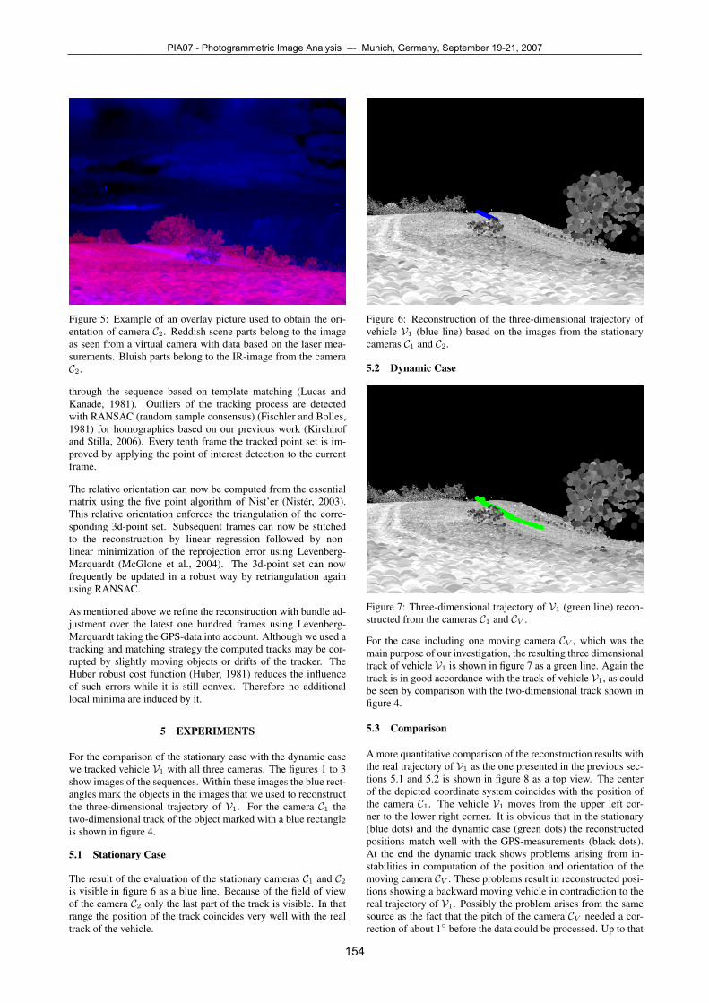
Figure 5: Example of an overlay picture used to obtain the ori-entation of camera C2. Reddish scene parts belong to the imageas seen from a virtual camera with data based on the laser mea-surements. Bluish parts belong to the IR-image from the cameraC2.
through the sequence based on template matching (Lucas andKanade, 1981). Outliers of the tracking process are detectedwith RANSAC (random sample consensus) (Fischler and Bolles,1981) for homographies based on our previous work (Kirchhofand Stilla, 2006). Every tenth frame the tracked point set is im-proved by applying the point of interest detection to the currentframe.
The relative orientation can now be computed from the essentialmatrix using the five point algorithm of Nist’er (Nister, 2003).This relative orientation enforces the triangulation of the corre-sponding 3d-point set. Subsequent frames can now be stitchedto the reconstruction by linear regression followed by non-linear minimization of the reprojection error using Levenberg-Marquardt (McGlone et al., 2004). The 3d-point set can nowfrequently be updated in a robust way by retriangulation againusing RANSAC.
As mentioned above we refine the reconstruction with bundle ad-justment over the latest one hundred frames using Levenberg-Marquardt taking the GPS-data into account. Although we used atracking and matching strategy the computed tracks may be cor-rupted by slightly moving objects or drifts of the tracker. TheHuber robust cost function (Huber, 1981) reduces the influenceof such errors while it is still convex. Therefore no additionallocal minima are induced by it.
5 EXPERIMENTS
For the comparison of the stationary case with the dynamic casewe tracked vehicle V1 with all three cameras. The figures 1 to 3show images of the sequences. Within these images the blue rect-angles mark the objects in the images that we used to reconstructthe three-dimensional trajectory of V1. For the camera C1 thetwo-dimensional track of the object marked with a blue rectangleis shown in figure 4.
5.1 Stationary Case
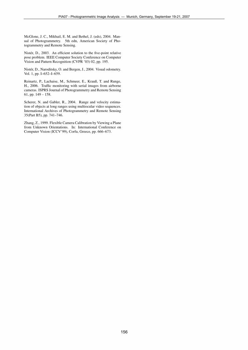
The result of the evaluation of the stationary cameras C1 and C2is visible in figure 6 as a blue line. Because of the field of viewof the camera C2 only the last part of the track is visible. In thatrange the position of the track coincides very well with the realtrack of the vehicle.
Figure 6: Reconstruction of the three-dimensional trajectory ofvehicle V1 (blue line) based on the images from the stationarycameras C1 and C2.
5.2 Dynamic Case
Figure 7: Three-dimensional trajectory of V1 (green line) recon-structed from the cameras C1 and CV .
For the case including one moving camera CV , which was themain purpose of our investigation, the resulting three dimensionaltrack of vehicle V1 is shown in figure 7 as a green line. Again thetrack is in good accordance with the track of vehicle V1, as couldbe seen by comparison with the two-dimensional track shown infigure 4.
5.3 Comparison
A more quantitative comparison of the reconstruction results withthe real trajectory of V1 as the one presented in the previous sec-tions 5.1 and 5.2 is shown in figure 8 as a top view. The centerof the depicted coordinate system coincides with the position ofthe camera C1. The vehicle V1 moves from the upper left cor-ner to the lower right corner. It is obvious that in the stationary(blue dots) and the dynamic case (green dots) the reconstructedpositions match well with the GPS-measurements (black dots).At the end the dynamic track shows problems arising from in-stabilities in computation of the position and orientation of themoving camera CV . These problems result in reconstructed posi-tions showing a backward moving vehicle in contradiction to thereal trajectory of V1. Possibly the problem arises from the samesource as the fact that the pitch of the camera CV needed a cor-rection of about 1◦ before the data could be processed. Up to that
PIA07 - Photogrammetric Image Analysis --- Munich, Germany, September 19-21, 2007¯¯¯¯¯¯¯¯¯¯¯¯¯¯¯¯¯¯¯¯¯¯¯¯¯¯¯¯¯¯¯¯¯¯¯¯¯¯¯¯¯¯¯¯¯¯¯¯¯¯¯¯¯¯¯¯¯¯¯¯¯¯¯¯¯¯¯¯¯¯¯¯¯¯¯¯¯¯¯¯¯¯¯¯¯¯¯¯¯¯¯¯¯¯¯¯¯¯¯¯¯¯¯¯¯¯¯¯¯
154

point the results are quite good, as seen in the transition to thetrack reconstructed from the stationary cameras.
Figure 8: Comparison between the positions obtained in the sta-tionary (marked by green dots) and the dynamic (blue dots) casewith GPS-measurements. Black dots represent the positions ofvehicle V1 as measured with G1.
Based on the good three-dimensional reconstruction of the posi-tion it is now possible to derive the velocity of the vehicle V1.The velocity is calculated as a running linear regression over 15time points. Figure 9 shows the results as green dots for the dy-namic case and blue dots for the stationary case. The mean ve-locity value from the GPS-data is shown as a black line. For bothcases the velocities vary around the mean value obtained fromthe GPS-data. Obviously the velocity values from the dynamiccase are distorted by the reconstruction problems of the trajectorymentioned in the previous paragraph, which start at 26.5 secondsin figure 9. On the other hand it is seen, that without these prob-lems the stationary data are a good continuation of dynamic ones.Furthermore the figure shows that the variation of the velocity ob-tained from the dynamic case (up to 26.5 seconds) is equal to thevariation of the velocity obtained from the stationary case.
Figure 9: Comparison of the velocities obtained from the station-ary (marked by green dots) and the dynamic (blue dots) case. Thehorizontal black line represents the mean velocity obtained fromthe GPS-data.
6 CONCLUSION
We described the results obtained from systems for automatic ve-locity estimation from stereo data. One of the systems had a fixedstereo basis, the other had a varying stereo basis since the secondcamera of the stereo pair was mounted on a moving vehicle. Ithas been shown that the described approach is applicable in prin-ciple, provided that a high quality registration of all necessarydata is available.
The structure from motion methods need to be supported by addi-tional metrical information, e. g., GPS in our case. But the obtain-able results seem to depend strongly on the quality of this addi-tional information. In our case the velocity calculation was quitegood in the beginning, but failed when the position estimates ob-tained by the structure from motion approach break down. Fur-ther detailed investigations will be necessary to find the cause ofthis failure.
7 OUTLOOK
As we pointed out above the structure from motion approach isthe bottleneck of the presented work. The 3d registration canbe improved by considering not only the relative orientation ofthe monocular moving sensor but also the relative orientation be-tween the moving and the stationary sensor. This is in generala wide base stereo approach. Therefore the used descriptors forpoints of interest have to be replaced by rotational and scale (andin the optimal case affine) invariant descriptors like SIFT (Lowe,2004) - or MSR - features. Additional improvement can be ob-tained by detecting the moving objects and exclude them fromfurther processing.
8 ACKNOWLEDGMENTS
The work described above has been supported by BMVg (Bun-desverteidigungsministerium, German Ministry of Defense) andBWB (Bundesamt fur Wehrtechnik und Beschaffung, GermanOffice for Armament and Procurement). The assistance of theWTD 81 (Wehrtechnische Dienststelle fur Informationstechnolo-gie und Elektronik) for preparation and realization of the mea-surement campaign at Greding in September 2006 is gratefullyacknowledged.
REFERENCES
Fischler, M. A. and Bolles, R. C., 1981. Random Sample Con-sensus: A Paradigm for Model Fitting with Applications to Im-age Analysis and Automated Cartography. Communications ofthe Association for Computing Machinery 24(6), pp. 381–395.
Forstner, W. and Gulch, E., 1987. A Fast Operator for Detectionand Precise Location of Distinct Points, Corners and Centres ofCircular Features. In: ISPRS Intercommission Workshop, Inter-laken.
Hartley, R. and Zisserman, A., 2000. Multiple View Geometry inComputer Vision. Cambridge University Press, Cambridge, UK.
Hebel, M., Bers, K.-H. and Jager, K., 2006. Imaging sensor fu-sion and enhanced vision for helicopter landing operations. In:J. J. G. Jacques G Verly (ed.), Signal Processing, Sensor Fusionand Target Recognition XV, Vol. 6226, SPIE.
Huber, P. J., 1981. Robust Statistics. John Wiley Publishers.
Kirchhof, M. and Stilla, U., 2006. Detection of moving objects inairborne thermal videos. ISPRS Journal of Photogrammetry andRemote Sensing 61, pp. 187 – 196.
Lowe, D., 2004. Distinctive image features from scale-invariantkeypoints. Int. J. of Computer Vision 60(2), pp. 91–110.
Lucas, B. T. and Kanade, T., 1981. An Iterative Image Registra-tion Technique with an Application to Stereo Vision. In: Proc. ofImage Understanding Workshop, pp. 212–130.
In: Stilla U et al (Eds) PIA07. International Archives of Photogrammetry, Remote Sensing and Spatial Information Sciences, 36 (3/W49B)¯¯¯¯¯¯¯¯¯¯¯¯¯¯¯¯¯¯¯¯¯¯¯¯¯¯¯¯¯¯¯¯¯¯¯¯¯¯¯¯¯¯¯¯¯¯¯¯¯¯¯¯¯¯¯¯¯¯¯¯¯¯¯¯¯¯¯¯¯¯¯¯¯¯¯¯¯¯¯¯¯¯¯¯¯¯¯¯¯¯¯¯¯¯¯¯¯¯¯¯¯¯¯¯¯¯¯¯¯
155
McGlone, J. C., Mikhail, E. M. and Bethel, J. (eds), 2004. Man-ual of Photogrammetry. 5th edn, American Society of Pho-togrammetry and Remote Sensing.
Nister, D., 2003. An efficient solution to the five-point relativepose problem. IEEE Computer Society Conference on ComputerVision and Pattern Recognition (CVPR ’03) 02, pp. 195.
Nister, D., Naroditsky, O. and Bergen, J., 2004. Visual odometry.Vol. 1, pp. I–652–I–659.
Reinartz, P., Lachaise, M., Schmeer, E., Krauß, T. and Runge,H., 2006. Traffic monitoring with serial images from airbornecameras. ISPRS Journal of Photogrammetry and Remote Sensing61, pp. 149 – 158.
Scherer, N. and Gabler, R., 2004. Range and velocity estima-tion of objects at long ranges using multiocular video sequences.International Archives of Photogrammetry and Remote Sensing35(Part B5), pp. 741–746.
Zhang, Z., 1999. Flexible Camera Calibration by Viewing a Planefrom Unknown Orientations. In: International Conference onComputer Vision (ICCV’99), Corfu, Greece, pp. 666–673.
PIA07 - Photogrammetric Image Analysis --- Munich, Germany, September 19-21, 2007¯¯¯¯¯¯¯¯¯¯¯¯¯¯¯¯¯¯¯¯¯¯¯¯¯¯¯¯¯¯¯¯¯¯¯¯¯¯¯¯¯¯¯¯¯¯¯¯¯¯¯¯¯¯¯¯¯¯¯¯¯¯¯¯¯¯¯¯¯¯¯¯¯¯¯¯¯¯¯¯¯¯¯¯¯¯¯¯¯¯¯¯¯¯¯¯¯¯¯¯¯¯¯¯¯¯¯¯¯
156