automatic vehicle identification system (avi) training
TRANSCRIPT
System: AVI Title: AVI Training Manual Chapter 9: Procedures
Owner: APICS Page 1 of 29 Revision: 1.1
Document: Chp9 Procedures.doc Revised: 2008 Feb 27
Automatic Vehicle Identification System (AVI)
Training Manual
Chapter 9: Procedure
System: AVI Title: AVI Training Manual Chapter 9: Procedures
Owner: APICS Page 2 of 29 Revision: 1.1
Document: Chp9 Procedures.doc Revised: 2008 Feb 27
TABLE OF CONTENTS
9 PROCEDURES .......................................................................................................................4 9.1 AVI WORKCELL: MAINTENANCE PROCEDURES......................................................................4
9.1.1 Overview ......................................................................................................................4
9.1.2 AVI Workcell Logs .......................................................................................................4
9.1.3 AVI Workcell Databases ..............................................................................................4
9.1.4 Logging into the Workcell............................................................................................5
9.1.5 Viewing Logs................................................................................................................6
9.1.6 Stopping the Workcell Controller (WCC)..................................................................13
9.1.7 Starting the WCC .......................................................................................................14
9.2 AVI WORKCELL: BUILD OUT PROCEDURES .........................................................................15
9.2.1 Using APIC HMI applications to facilitate model year build out. ............................16
9.3 AVI WORKCELL: MARRIAGE RESEEDING.............................................................................20
9.3.1 Reseeding Procedure .................................................................................................21
9.4 AVI SUPERVISOR: CHANGEOVER PROCEDURES....................................................................27
9.4.1 Overview ....................................................................................................................27
9.4.2 Terms..........................................................................................................................27
9.4.3 AVI Supervisor PLC Organization ............................................................................28
9.4.4 PLC Change-over ......................................................................................................29

System: AVI Title: AVI Training Manual Chapter 9: Procedures
Owner: APICS Page 3 of 29 Revision: 1.1
Document: Chp9 Procedures.doc Revised: 2008 Feb 27
Document Revision History
Date Revision
Number
Name Description (include pages affected)
2008
Feb 27
1.1 Mas40 Change name to Chrysler
2006
Dec 15
1.0 MAS40 2006 AVI Training Manual Update Project
Supporting Documentation
The Chrysler documents listed below are instrumental in defining this chapter's systems and its
configuration.
Doc. No. Rev. Date Title Link
0.1 2000 Mar 31 Introduction to AVI Logs Request from APICS
Workcell team
2.2 2002 Jun 12 Configuring AVI Workcell Database Request from APICS
Workcell team
1.2 2006 Mar 16 AVI Multi-State Supervisor
Configuration and
User Manual
APICS web site
System: AVI Title: AVI Training Manual Chapter 9: Procedures
Owner: APICS Page 4 of 29 Revision: 1.1
Document: Chp9 Procedures.doc Revised: 2008 Feb 27
9 PROCEDURES
9.1 AVI Workcell: Maintenance Procedures
9.1.1 Overview
The RS6K AVI Workcell controllers boot on IBM AIX 5.3 systems and have
what is considered a boot IP address and a hostname. There is an “A” and a “B”
system. At any given time, only one system may be running the AVI applications
as the “service” box.
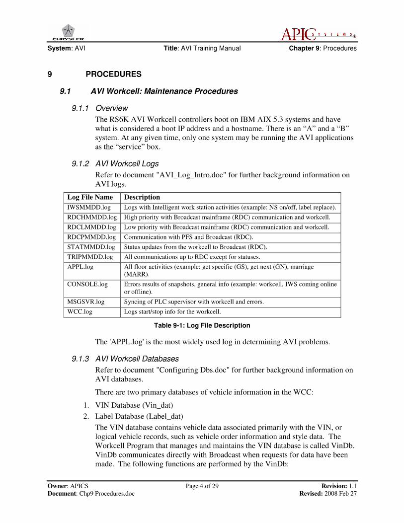
9.1.2 AVI Workcell Logs
Refer to document "AVI_Log_Intro.doc" for further background information on
AVI logs.
Log File Name Description
IWSMMDD.log Logs with Intelligent work station activities (example: NS on/off, label replace).
RDCHMMDD.log High priority with Broadcast mainframe (RDC) communication and workcell.
RDCLMMDD.log Low priority with Broadcast mainframe (RDC) communication and workcell.
RDCPMMDD.log Communication with PFS and Broadcast (RDC).
STATMMDD.log Status updates from the workcell to Broadcast (RDC).
TRIPMMDD.log All communications up to RDC except for statuses.
APPL.log All floor activities (example: get specific (GS), get next (GN), marriage
(MARR).
CONSOLE.log Errors results of snapshots, general info (example: workcell, IWS coming online
or offline).
MSGSVR.log Syncing of PLC supervisor with workcell and errors.
WCC.log Logs start/stop info for the workcell.
Table 9-1: Log File Description
The 'APPL.log' is the most widely used log in determining AVI problems.
9.1.3 AVI Workcell Databases
Refer to document "Configuring Dbs.doc" for further background information on
AVI databases.
There are two primary databases of vehicle information in the WCC:
1. VIN Database (Vin_dat)
2. Label Database (Label_dat)
The VIN database contains vehicle data associated primarily with the VIN, or
logical vehicle records, such as vehicle order information and style data. The
Workcell Program that manages and maintains the VIN database is called VinDb.
VinDb communicates directly with Broadcast when requests for data have been
made. The following functions are performed by the VinDb:
System: AVI Title: AVI Training Manual Chapter 9: Procedures
Owner: APICS Page 5 of 29 Revision: 1.1
Document: Chp9 Procedures.doc Revised: 2008 Feb 27
� Communicates with the mainframe and tells it the VIN of the last vehicle that
was downloaded from the mainframe to the Workcell
� Allocates, de-allocates, and updates vehicle information
� Initiates Next in Schedule (NS) Request processing
The Label database has a record for each label that is known to AVI. It contains
vehicle data primarily associated with a particular body, such as current location,
routing information, and quality data. It forwards label replacement information
to broadcast so that changes can be reflected on the mainframe.
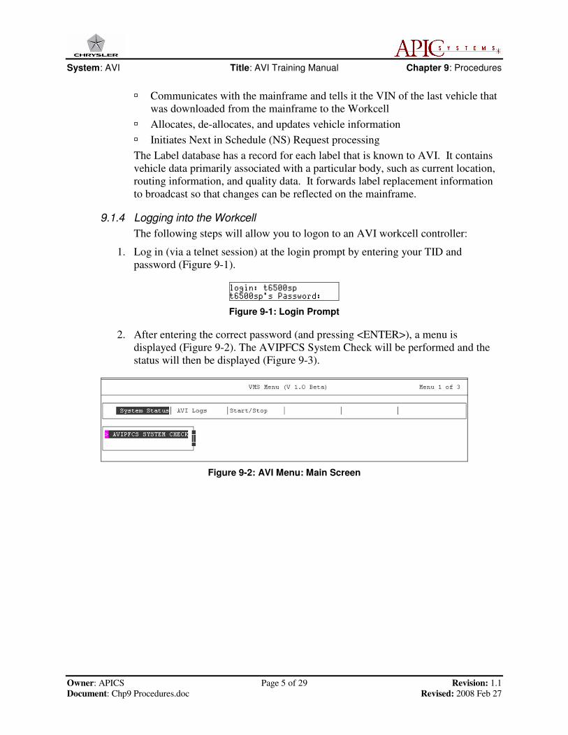
9.1.4 Logging into the Workcell
The following steps will allow you to logon to an AVI workcell controller:
1. Log in (via a telnet session) at the login prompt by entering your TID and
password (Figure 9-1).
Figure 9-1: Login Prompt
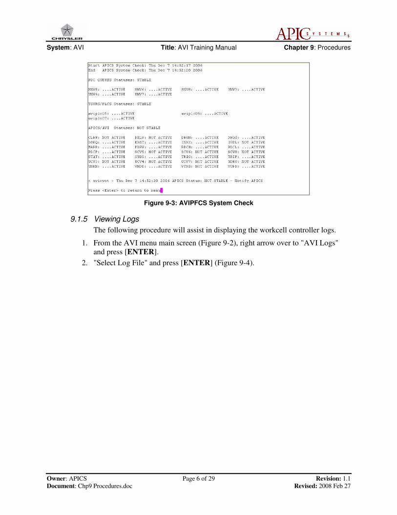
2. After entering the correct password (and pressing <ENTER>), a menu is
displayed (Figure 9-2). The AVIPFCS System Check will be performed and the
status will then be displayed (Figure 9-3).
Figure 9-2: AVI Menu: Main Screen
System: AVI Title: AVI Training Manual Chapter 9: Procedures
Owner: APICS Page 6 of 29 Revision: 1.1
Document: Chp9 Procedures.doc Revised: 2008 Feb 27
Figure 9-3: AVIPFCS System Check
9.1.5 Viewing Logs
The following procedure will assist in displaying the workcell controller logs.
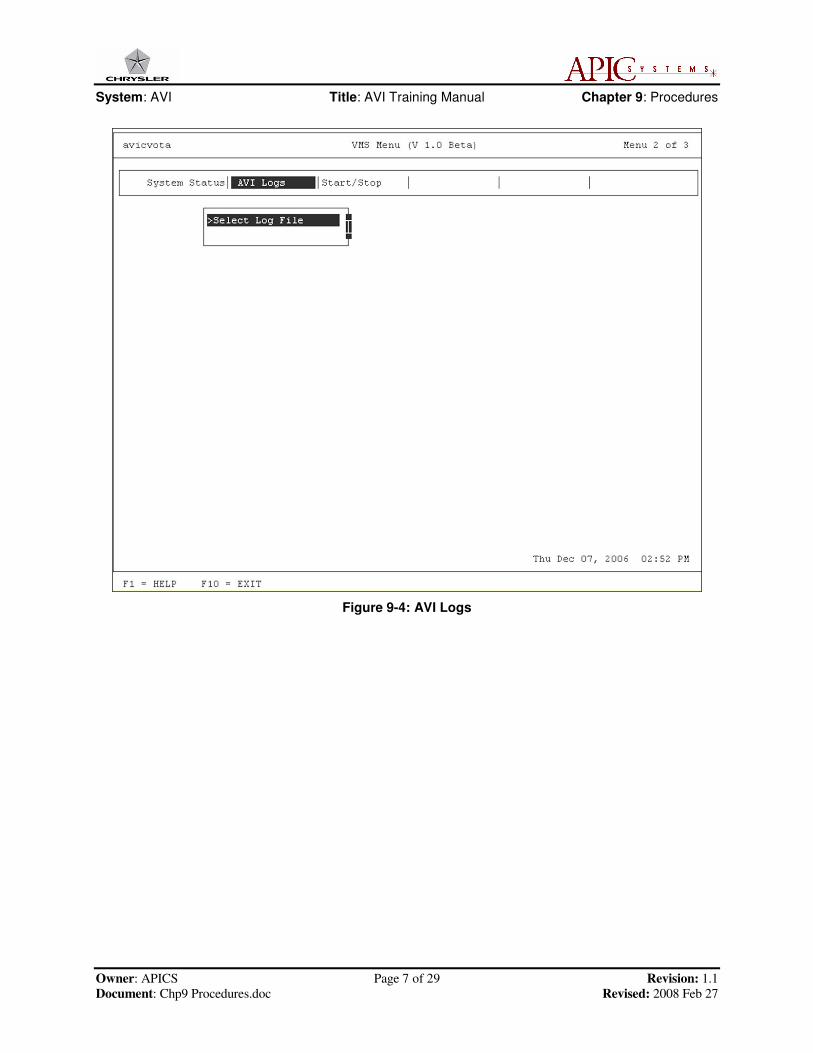
1. From the AVI menu main screen (Figure 9-2), right arrow over to "AVI Logs"
and press [ENTER].
2. "Select Log File" and press [ENTER] (Figure 9-4).
System: AVI Title: AVI Training Manual Chapter 9: Procedures
Owner: APICS Page 7 of 29 Revision: 1.1
Document: Chp9 Procedures.doc Revised: 2008 Feb 27
Figure 9-4: AVI Logs
System: AVI Title: AVI Training Manual Chapter 9: Procedures
Owner: APICS Page 8 of 29 Revision: 1.1
Document: Chp9 Procedures.doc Revised: 2008 Feb 27
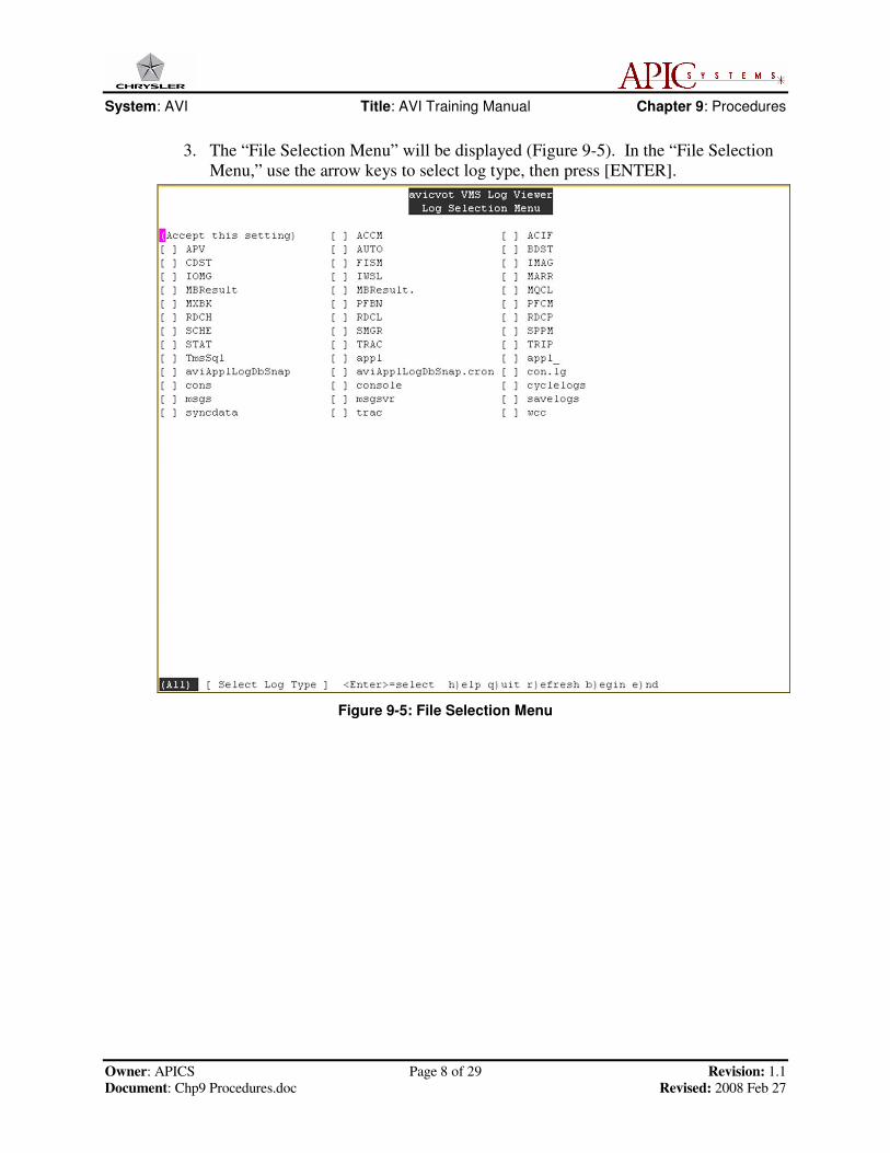
3. The “File Selection Menu” will be displayed (Figure 9-5). In the “File Selection
Menu,” use the arrow keys to select log type, then press [ENTER].
Figure 9-5: File Selection Menu
System: AVI Title: AVI Training Manual Chapter 9: Procedures
Owner: APICS Page 9 of 29 Revision: 1.1
Document: Chp9 Procedures.doc Revised: 2008 Feb 27
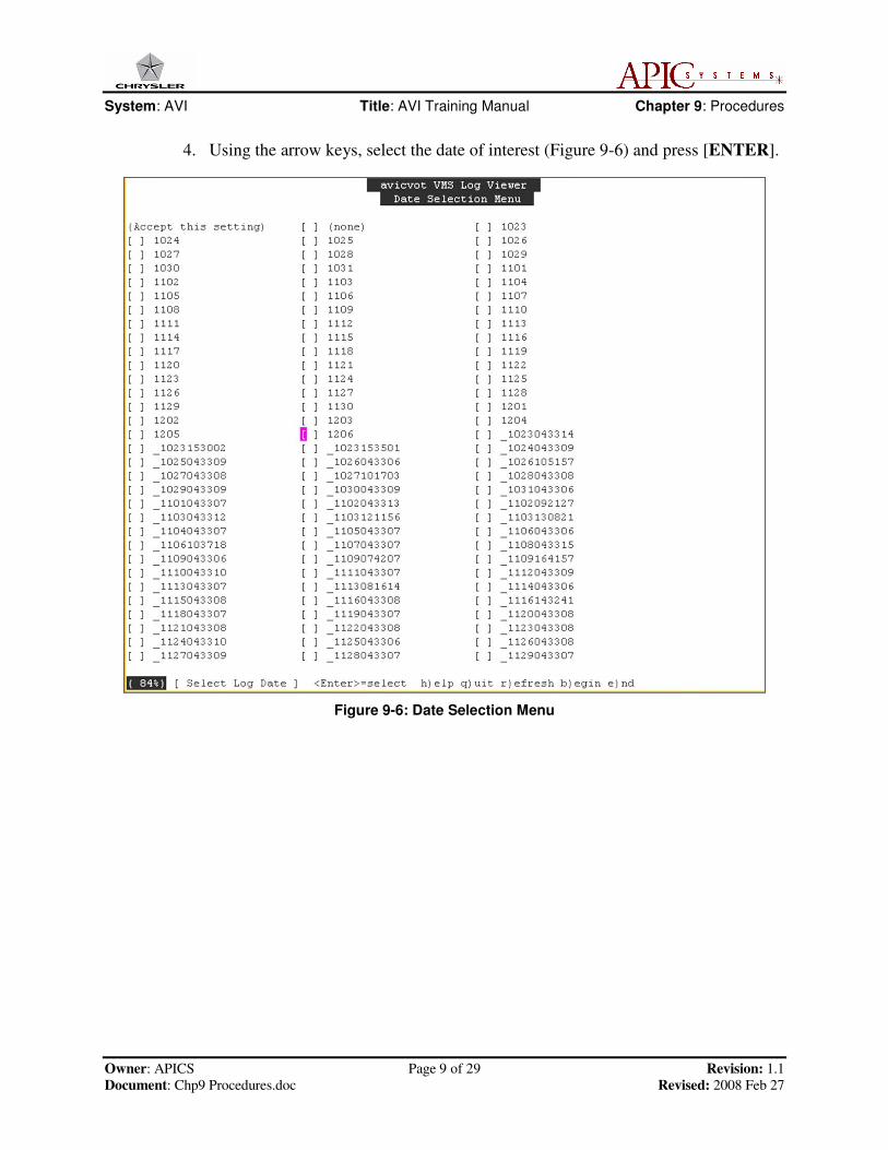
4. Using the arrow keys, select the date of interest (Figure 9-6) and press [ENTER].
Figure 9-6: Date Selection Menu
System: AVI Title: AVI Training Manual Chapter 9: Procedures
Owner: APICS Page 10 of 29 Revision: 1.1
Document: Chp9 Procedures.doc Revised: 2008 Feb 27
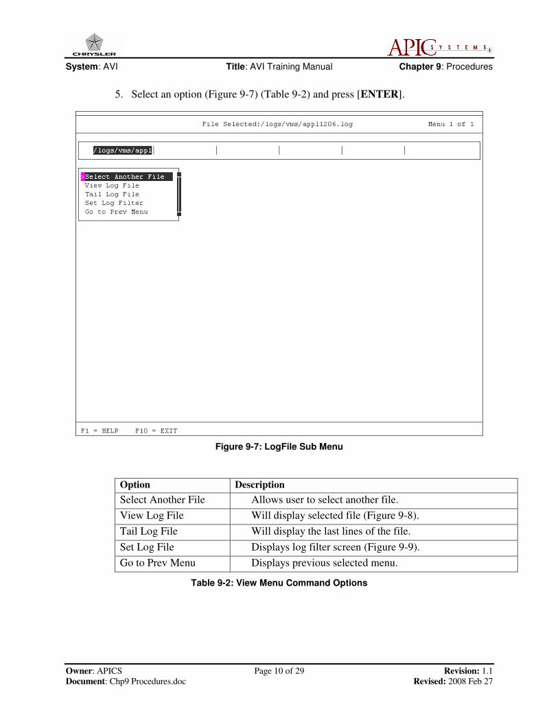
5. Select an option (Figure 9-7) (Table 9-2) and press [ENTER].
Figure 9-7: LogFile Sub Menu
Option Description
Select Another File Allows user to select another file.
View Log File Will display selected file (Figure 9-8).
Tail Log File Will display the last lines of the file.
Set Log File Displays log filter screen (Figure 9-9).
Go to Prev Menu Displays previous selected menu.
Table 9-2: View Menu Command Options
System: AVI Title: AVI Training Manual Chapter 9: Procedures
Owner: APICS Page 11 of 29 Revision: 1.1
Document: Chp9 Procedures.doc Revised: 2008 Feb 27
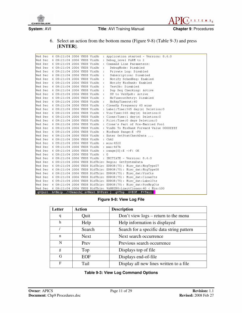
6. Select an action from the bottom menu (Figure 9-8) (Table 9-3) and press
[ENTER].
Figure 9-8: View Log File
Letter Action Description
q Quit Don’t view logs – return to the menu
h Help Help information is displayed
/ Search Search for a specific data string pattern
n Next Next search occurrence
N Prev Previous search occurrence
g Top Displays top of file
G EOF Displays end-of-file
F Tail Display all new lines written to a file
Table 9-3: View Log Command Options

System: AVI Title: AVI Training Manual Chapter 9: Procedures
Owner: APICS Page 12 of 29 Revision: 1.1
Document: Chp9 Procedures.doc Revised: 2008 Feb 27
7. Select an action from the Set Log File menu (Figure 9-9) (Table 9-4) and press
[ENTER]. Use a combination of filter selections to build your own filter. The
choices and results of the filter selections will appear on the lower portion of this
screen.
Figure 9-9: Set Log Filter
Item Action Description
1 Return Return to the menu
2 Filter by Hour Allows “hour to hour” filter range selection
3 Filter by VIN/Label Allows VIN/label filter selection
4 Filter by Point Allows AVI point number filter selection
5 Build Your Own Filter Use any combinations of filter selections
6 Clear All Filters Clears all filter selections
7 View Filtered Log Displays the filtered log
8 Email Log File Send an Email of log file
Table 9-4: Filter Menu Descriptions

System: AVI Title: AVI Training Manual Chapter 9: Procedures
Owner: APICS Page 13 of 29 Revision: 1.1
Document: Chp9 Procedures.doc Revised: 2008 Feb 27
9.1.6 Stopping the Workcell Controller (WCC)
Stop the workcell controller using the following steps:
1. Use the arrow keys to select “Start/Stop” from the menu (Figure 9-10) then select
“Stop” and press [ENTER].
Figure 9-10: Start/Stop Menu (with “Stop” Selected)
2. Answer “y” at the prompt “ARE YOU SURE YOU WANT TO STOP WCC
FUNCTIONS.” The workcell will then begin to stop the AVI application, the
PFCS applications, and the platform applications. The workcell will reconfigure
itself onto its boot IP address and hostname.
When the process is complete, a screen similar to Figure 9-11 will be displayed.
Figure 9-11: Screen Displayed When WCC Has Been Stopped
3. On the console, press [ENTER] to return to the main menu. Using a telnet
session, open another session to the BOOT address/hostname.
System: AVI Title: AVI Training Manual Chapter 9: Procedures
Owner: APICS Page 14 of 29 Revision: 1.1
Document: Chp9 Procedures.doc Revised: 2008 Feb 27
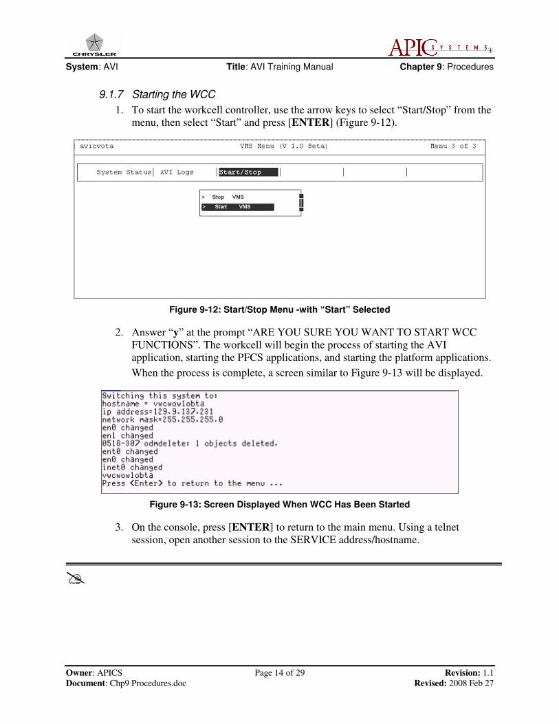
9.1.7 Starting the WCC
1. To start the workcell controller, use the arrow keys to select “Start/Stop” from the
menu, then select “Start” and press [ENTER] (Figure 9-12).
Figure 9-12: Start/Stop Menu -with “Start” Selected
2. Answer “y” at the prompt “ARE YOU SURE YOU WANT TO START WCC
FUNCTIONS”. The workcell will begin the process of starting the AVI
application, starting the PFCS applications, and starting the platform applications.
When the process is complete, a screen similar to Figure 9-13 will be displayed.
Figure 9-13: Screen Displayed When WCC Has Been Started
3. On the console, press [ENTER] to return to the main menu. Using a telnet
session, open another session to the SERVICE address/hostname.
�

System: AVI Title: AVI Training Manual Chapter 9: Procedures
Owner: APICS Page 15 of 29 Revision: 1.1
Document: Chp9 Procedures.doc Revised: 2008 Feb 27
9.2 AVI Workcell: Build Out Procedures
The following is a list of procedures related to the build out process that the plant
ITM personnel will use to build out the model year vehicles. These procedures are
listed in sequence and will be performed by experienced plant ITM personnel. Some
procedures may require contacting the APICS support group for assistance or by
having APICS support perform these procedures remotely.
1. NS Request Stop
a. Increase pre-marriage count.
b. Stop NS request at last marriage using IWS “Stop and Start NS Request”
screen.
c. See section “Using APICS HMI applications to facilitate model year build
out”
2. Clean-Up AVI Database
a. Run IWS “Aging Screen Report” to list VINs between certain points that
have not been touched in more than 48 hours. If uncertain call APICS
support.
b. Locate clone VINs that are unmarried.
c. Run IWS “Aging Screen Report” several times a day.
3. Reset Setup Point
a. Reset by downloading AVI setup points by broadcast group.
4. Recovery of database from broadcast.
a. Download AVI data.
5. Initialize Marriage Application
6. Fix next new VIN record in miscellaneous data.
7. Start NS Request. (Plant Scheduling)
8. Fix PES rules if needed. (Sales code conversions)
9. Ask broadcast to fix PARM card if needed.
a. May need to adjust PARM card to pull remaining non-married from
Broadcast. (Broadcast)
10. Fix production year in clone template that is defined in the vehicle code database.
11. Clean VIN and label database, then perform a recovery of data from broadcast.
System: AVI Title: AVI Training Manual Chapter 9: Procedures
Owner: APICS Page 16 of 29 Revision: 1.1
Document: Chp9 Procedures.doc Revised: 2008 Feb 27
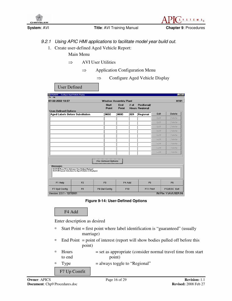
9.2.1 Using APIC HMI applications to facilitate model year build out.
1. Create user-defined Aged Vehicle Report:
Main Menu
⇒ AVI User Utilities
⇒ Application Configuration Menu
⇒ Configure Aged Vehicle Display
Figure 9-14: User-Defined Options
Enter description as desired
� Start Point = first point where label identification is “guaranteed” (usually
marriage)
� End Point = point of interest (report will show bodies pulled off before this
point)
� Hours = set as appropriate (consider normal travel time from start
to end point)
� Type = always toggle to “Regional”
User Defined
F4 Add
F7 Up Comfit
System: AVI Title: AVI Training Manual Chapter 9: Procedures
Owner: APICS Page 17 of 29 Revision: 1.1
Document: Chp9 Procedures.doc Revised: 2008 Feb 27
2. Return to Main Menu
3. Run Aged Vehicle application
Main Menu
⇒ Vehicle Info Menu
⇒ Aged Vehicles
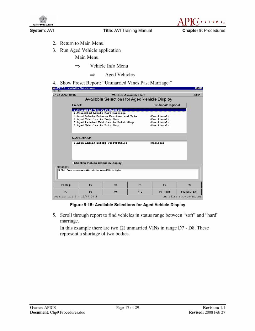
4. Show Preset Report: “Unmarried Vines Past Marriage.”
Figure 9-15: Available Selections for Aged Vehicle Display
5. Scroll through report to find vehicles in status range between “soft” and “hard”
marriage.
In this example there are two (2) unmarried VINs in range D7 - D8. These
represent a shortage of two bodies.
System: AVI Title: AVI Training Manual Chapter 9: Procedures
Owner: APICS Page 18 of 29 Revision: 1.1
Document: Chp9 Procedures.doc Revised: 2008 Feb 27
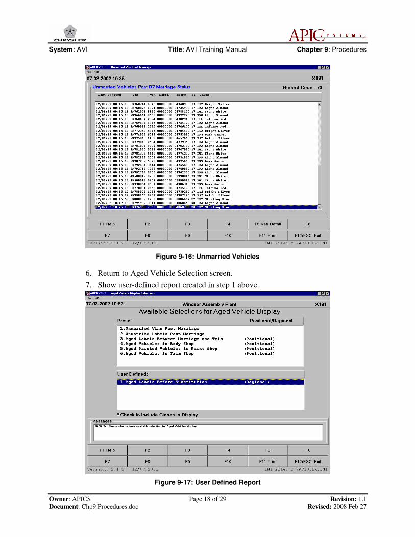
Figure 9-16: Unmarried Vehicles
6. Return to Aged Vehicle Selection screen.
7. Show user-defined report created in step 1 above.
Figure 9-17: User Defined Report

System: AVI Title: AVI Training Manual Chapter 9: Procedures
Owner: APICS Page 19 of 29 Revision: 1.1
Document: Chp9 Procedures.doc Revised: 2008 Feb 27
8. Identify all married labels.
Figure 9-18: Identified Married Labels
In this example, there are six (6) married Labels which have not progressed to
substitution. These represent a shortage of six bodies.
9. Conclusion: Based on the AVI reports in this example, there is a shortage of 8
bodies prior to substitution. This number of units must be inserted at the start of
process (check body styles!!)
�
System: AVI Title: AVI Training Manual Chapter 9: Procedures
Owner: APICS Page 20 of 29 Revision: 1.1
Document: Chp9 Procedures.doc Revised: 2008 Feb 27
9.3 AVI Workcell: Marriage Reseeding
Reseeding is the process of reinserting units into the assembly line for vehicle
production. The reseeding procedure is described in Section 9.3.1.
The user must be familiar with the following terms in order to reseed the assembly
line.
♦ Marriage Point: Where metal and vehicle options are joined together
♦ Marriage Type: Options that is associated with a specify model
♦ Gate Line Sequence Number: The number assigned at time of vehicle order
♦ Set up Number: Assigned during the seeding for build order of product
System: AVI Title: AVI Training Manual Chapter 9: Procedures
Owner: APICS Page 21 of 29 Revision: 1.1
Document: Chp9 Procedures.doc Revised: 2008 Feb 27
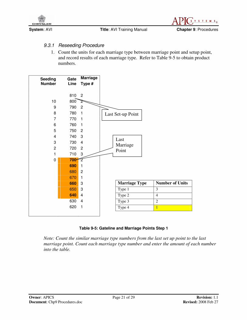
9.3.1 Reseeding Procedure
1. Count the units for each marriage type between marriage point and setup point,
and record results of each marriage type. Refer to Table 9-5 to obtain product
numbers.
Table 9-5: Gateline and Marriage Points Step 1
Note: Count the similar marriage type numbers from the last set up point to the last
marriage point. Count each marriage type number and enter the amount of each number
into the table.
Seeding Number
Gate Line
Marriage
Type #
810 2
10 800 2
9 790 2
8 780 1
7 770 1
6 760 1
5 750 2
4 740 3
3 730 4
2 720 2
1 710 3
0 700 2
690 1
680 2
670 1
660 3
650 3
640 4
630 4
620 1
Last Set-up Point
Last
Marriage
Point
Marriage Type Number of Units
Type 1 3
Type 2 4
Type 3 2
Type 4 1
System: AVI Title: AVI Training Manual Chapter 9: Procedures
Owner: APICS Page 22 of 29 Revision: 1.1
Document: Chp9 Procedures.doc Revised: 2008 Feb 27
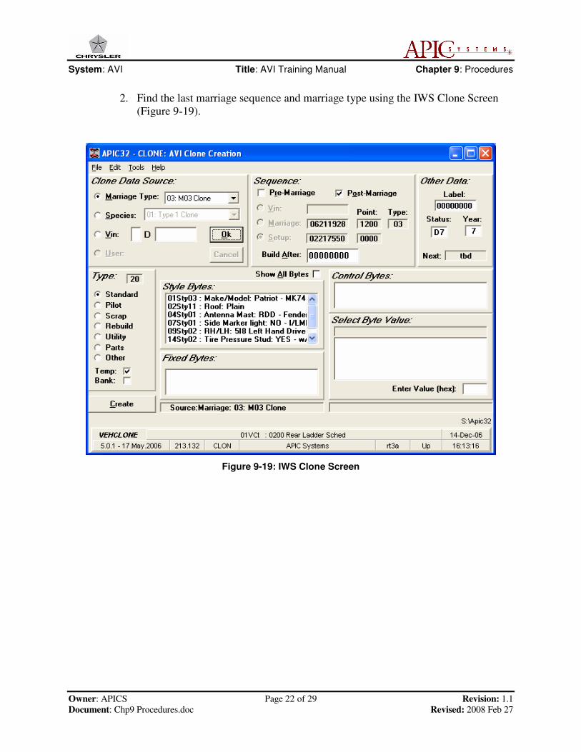
2. Find the last marriage sequence and marriage type using the IWS Clone Screen
(Figure 9-19).
Figure 9-19: IWS Clone Screen

System: AVI Title: AVI Training Manual Chapter 9: Procedures
Owner: APICS Page 23 of 29 Revision: 1.1
Document: Chp9 Procedures.doc Revised: 2008 Feb 27
3. Find the lowest Gate Line Sequence (Table 9-6) from all marriage types.
Table 9-6: Gate Line Sequence Chart Step 3
Note: Count all the marriage types and the number of units within each marriage. Then,
determine which marriage type has the lowest Gate Line Sequence Number of the entire
group.
Seeding Number
Gate Line
Marriage
Type
810 2
10 800 2
9 790 2
8 780 1
7 770 1
6 760 1
5 750 2
4 740 3
3 730 4
2 720 2
1 710 3
0 700 2
690 1
680 2
670 1
660 3
650 3
640 4
630 4
620 1
Lowest Gate Line Sequence
Number for each Marriage Type
Type 1 = 690
Type 2 = 700
Type 3 = 660
Type 4 = 640
Type 4 is the lowest of the group
System: AVI Title: AVI Training Manual Chapter 9: Procedures
Owner: APICS Page 24 of 29 Revision: 1.1
Document: Chp9 Procedures.doc Revised: 2008 Feb 27
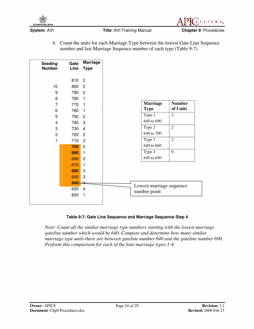
4. Count the units for each Marriage Type between the lowest Gate Line Sequence
number and last Marriage Sequence number of each type (Table 9-7).
Table 9-7: Gate Line Sequence and Marriage Sequence Step 4
Note: Count all the similar marriage type numbers starting with the lowest marriage
gateline number which would be 640. Compare and determine how many similar
marriage type units there are between gateline number 640 and the gateline number 690.
Perform this comparison for each of the four marriage types 1-4.
Seeding Number
Gate Line
Marriage
Type
810 2
10 800 2
9 790 2
8 780 1
7 770 1
6 760 1
5 750 2
4 740 3
3 730 4
2 720 2
1 710 3
700 2
690 1
680 2
670 1
660 3
650 3
640 4
630 4
620 1
Marriage
Type
Number
of Units
Type 1
640 to 690
2
Type 2
640 to 700
2
Type 3
640 to 660
2
Type 4
640 to 640
0
Lowest marriage sequence
number point
System: AVI Title: AVI Training Manual Chapter 9: Procedures
Owner: APICS Page 25 of 29 Revision: 1.1
Document: Chp9 Procedures.doc Revised: 2008 Feb 27
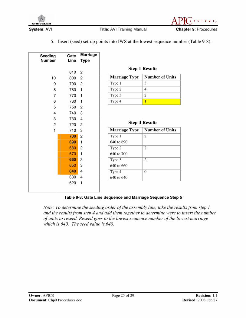
5. Insert (seed) set-up points into IWS at the lowest sequence number (Table 9-8).
Step 1 Results
Step 4 Results
Table 9-8: Gate Line Sequence and Marriage Sequence Step 5
Note: To determine the seeding order of the assembly line, take the results from step 1
and the results from step 4 and add them together to determine were to insert the number
of units to reseed. Reseed goes to the lowest sequence number of the lowest marriage
which is 640. The seed value is 640.
Seeding Number
Gate Line
Marriage
Type
810 2
10 800 2
9 790 2
8 780 1
7 770 1
6 760 1
5 750 2
4 740 3
3 730 4
2 720 2
1 710 3
700 2
690 1
680 2
670 1
660 3
650 3
640 4
630 4
620 1
Marriage Type Number of Units
Type 1 3
Type 2 4
Type 3 2
Type 4 1
Marriage Type Number of Units
Type 1
640 to 690
2
Type 2
640 to 700
2
Type 3
640 to 660
2
Type 4
640 to 640
0
System: AVI Title: AVI Training Manual Chapter 9: Procedures
Owner: APICS Page 26 of 29 Revision: 1.1
Document: Chp9 Procedures.doc Revised: 2008 Feb 27
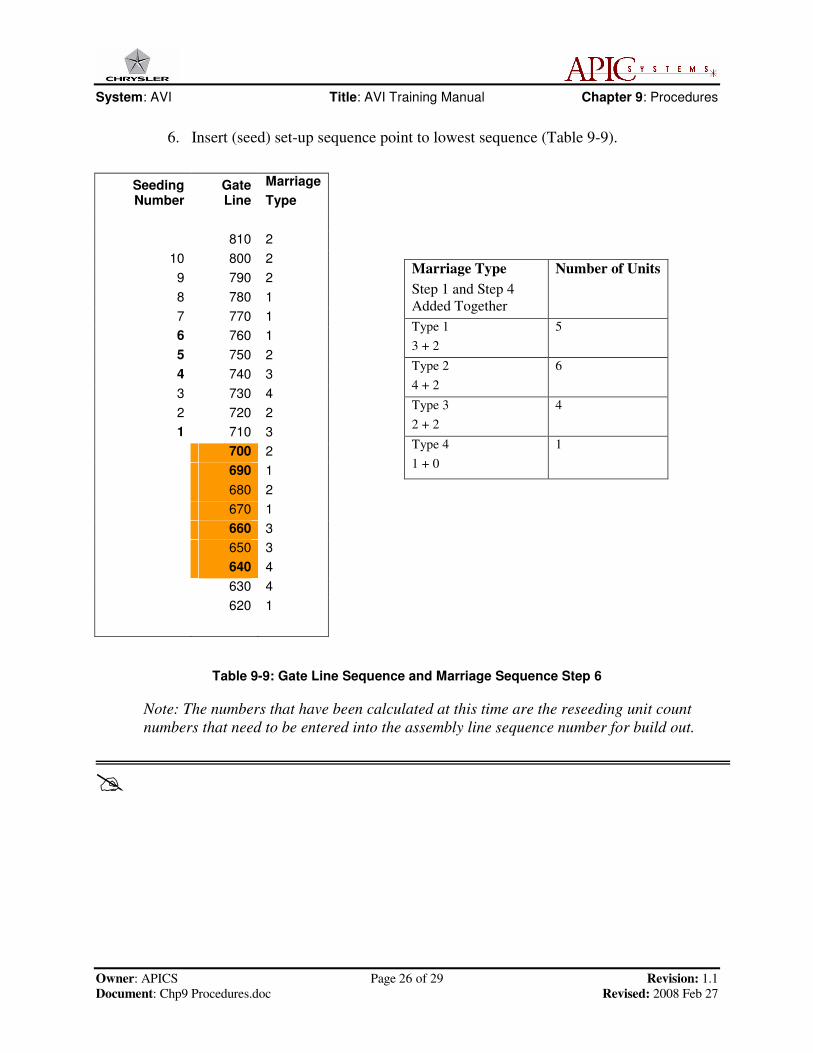
6. Insert (seed) set-up sequence point to lowest sequence (Table 9-9).
Table 9-9: Gate Line Sequence and Marriage Sequence Step 6
Note: The numbers that have been calculated at this time are the reseeding unit count
numbers that need to be entered into the assembly line sequence number for build out.
�
Seeding Number
Gate Line
Marriage
Type
810 2
10 800 2
9 790 2
8 780 1
7 770 1
6 760 1
5 750 2
4 740 3
3 730 4
2 720 2
1 710 3
700 2
690 1
680 2
670 1
660 3
650 3
640 4
630 4
620 1
Marriage Type
Step 1 and Step 4
Added Together
Number of Units
Type 1
3 + 2
5
Type 2
4 + 2
6
Type 3
2 + 2
4
Type 4
1 + 0
1
System: AVI Title: AVI Training Manual Chapter 9: Procedures
Owner: APICS Page 27 of 29 Revision: 1.1
Document: Chp9 Procedures.doc Revised: 2008 Feb 27
9.4 AVI Supervisor: Changeover Procedures
9.4.1 Overview
For Supervisor configuration, refer to Chapter 5 Plant Floor Installation and
Configuration of the AVI Training Manual. Also refer to document "AVI Multi-
State Supervisor Configuration and User Manual".
To complete the supervisor change over procedures, the person completing these
procedures must meet some minimum requirements as described below.
� Working knowledge of PLCs
� General wiring practices
� Equipment needed to implement supervisor change over procedures is:
� Rockwell Software
� AI5 series programming software or equivalent
� Connectivity to the supervisor PLCs
9.4.2 Terms
A user must be familiar with the following terms in order to back-up or change over
the Supervisor PLCs for AVI.
� AVI Workcell: A RSC 6000 computer that controls the AVI system.
� Supervisor PLC: Six PLCs 5/60’s that are used as data concentrators for AVI
messaging between the AVI Workcell Controller and Plant Floor PLCs that
are running the AVI Driver. Three Supervisory PLCs control the messaging
between the AVI Work Cell and area Plant Floor PLCs. These areas are BIW,
Paint, and TCF. The other three Supervisor PLCs are ready back-ups.
� DCM: The remote I/O network connected between the Supervisor PLCs and
Plant Floor PLCs that are running the AVI Driver. This network is used solely
for AVI messaging.
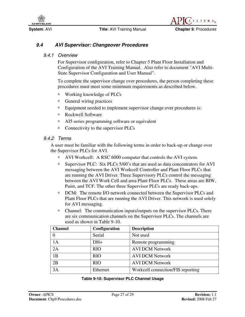
� Channel: The communication inputs/outputs on the supervisor PLCs. There
are six communication channels on the Supervisor PLCs. The channels are
used as shown in Table 9-10.
Channel Configuration Description
0 Serial Not used
1A DH+ Remote programming
2A RIO AVI DCM Network
1B RIO AVI DCM Network
2B RIO AVI DCM Network
3A Ethernet Workcell connection/FIS reporting
Table 9-10: Supervisor PLC Channel Usage
System: AVI Title: AVI Training Manual Chapter 9: Procedures
Owner: APICS Page 28 of 29 Revision: 1.1
Document: Chp9 Procedures.doc Revised: 2008 Feb 27
9.4.3 AVI Supervisor PLC Organization
The Supervisor PLCs are named as follows (MS indicates “Main Supervisor”):
� AVI1_MS
� AVI2_MS
� AVI3_MS
� AVI4_MS
� AVI5_MS
� AVI6_MS
The main/back-up Supervisor PLCs are paired as follows:
� AVI1_MS and AVI4_MS (BIW)
� AVI2_MS and AVI5_MS (Paint)
� AVI3_MS and AVI6_MS (TCF)
Each Main Supervisor PLC has only one Back-up Supervisor PLC. The
supervisor PLC that is on-line and running will be considered the main.
Note: If an assembly plant has only one Back-up Supervisory PLC, the Back-Up
Supervisor PLC will need to have the current Supervisor PLC program for the area it
will back up (BIW, Paint, TCF) before the Change Over Procedure can be accomplished.
All six Supervisor PLCs will be connected to a central programming workstation
(PWS, a PC with PLC logic programming software loaded onto it).
The three main supervisor programs will be backed up weekly and stored on the
central PWS. When the back-ups are completed, the most current program will be
loaded to the associated paired Supervisor PLCs.
On a monthly basis, the cabling will be switched to make the current Back-up
Supervisor PLCs the new Main Supervisor PLCs (see Change Over Procedures).
If a hardware malfunction occurs on any Main Supervisor PLCs, the cabling will
be switched to make the current Back-up Supervisor PLC the Main Supervisor
PLC (see Change Over Procedures).

System: AVI Title: AVI Training Manual Chapter 9: Procedures
Owner: APICS Page 29 of 29 Revision: 1.1
Document: Chp9 Procedures.doc Revised: 2008 Feb 27
9.4.4 PLC Change-over
The following procedure changes the Main Supervisor PLC to the Back-up
Supervisor PLC. This procedure is used for the monthly maintenance change
over, and for fault operation change over.
Note: If an assembly plant has only one Back-up Supervisory PLC, the Back-up
Supervisor PLC will need to have the current Supervisor PLC program for the area it
will back up (BIW, Paint, TCF) before the Change Over Procedure can be accomplished.
1. Verify that the Back-up Supervisor PLC has the latest supervisor program from
the central PWS.
2. Unplug the Remote I/O cables from the Main Supervisor PLC channels 1B, 2A,
and 2B. Plug these cables into the same channels on the Back-up Supervisor PLC.
3. Unplug the Ethernet cable from channel 3A of the Main Supervisor PLC and plug
the cable into channel 3A of the Back-up Supervisor PLC.
4. Turn the Back-up Supervisor PLC to “Remote Run” mode.
5. From the central PWS, connect the Back-up Supervisor PLC and verify
communication with the Workcell Controller and all links.
6. The Back-up Supervisor PLC is now the Main Supervisor PLC.
�