automatic transmission / trans ± automatic … · 4005r±02 d25120 add if hot ok if hot automatic...
TRANSCRIPT

4005R–02
D25120
Add if hot
OK if hot
–AUTOMATIC TRANSMISSION / TRANS AUTOMATIC TRANSAXLE FLUID40–1
2076Author�: Date�:
2002 CAMRY REPAIR MANUAL (RM881U)
AUTOMATIC TRANSAXLE FLUIDON–VEHICLE INSPECTION
1. CHECK FLUID LEVELHINT:Drive the vehicle so that the engine and transaxle are at normaloperating temperature.
Fluid temperature: 70 – 80 °C (158 – 176 °F)
(a) Park the vehicle on a level surface and set the parkingbrake.
(b) With the engine idling and the brake pedal depressed,shift the shift lever into all positions from P to L positionand return to P position.
(c) Take out the dipstick and wipe it clean.(d) Put it back fully into the pipe.(e) Take it out and check that the fluid level is in the HOT posi-
tion.If there are leaks, it is necessary to repair or replace O–rings,FIPGs, oil seals, plugs or other parts.

4005T–02
40–2–AUTOMATIC TRANSMISSION / TRANS AUTOMATIC TRANSAXLE ASSY
2077Author�: Date�:
2002 CAMRY REPAIR MANUAL (RM881U)
AUTOMATIC TRANSAXLE ASSYPRECAUTION1. The automatic transaxle is composed of highly precision–finished parts, necessitating careful
inspection before reassembly because even a small nick could cause fluid leakage or affectthe performance. The instructions here are organized so that you work on only one componentgroup at a time. This w ill help to avoid confusion from similar–looking parts of different sub–as-semblies being on your workbench at the same time. The component groups are inspected andrepaired from the converter housing side. Inspect, repair and reassemble as much as posiblebefore proceeding to the next component group. If a defect is found in a certain componentgroup during reassembly, inspect and repair this group immediately. If a component group can-not be assembled because parts are being ordered, be sure to keep all parts of the group in aseparate container while proceeding with disassembly, inspection, repair and reassembly ofother component groups.Recommended ATF: T–IV
2. All disassembled parts should be washed clean and any fluid passages and holes should beblown through with compressed air.
3. Dry all parts with compressed air, never use shop rags.4. When using compressed air, always do not aim at yourself to prevent accidentally spraying ATF
or kerosene on your face.5. The recommended automatic transaxle fluid or kerosene should be used for cleaning.6. After cleaning, the parts should be arranged in the correct order for efficient inspection, repairs,
and reassembly.7. When disassembling a valve body, be sure to match each valve together with the correspond-
ing spring.8. New discs for the brakes and clutches that are to be used for replacement must be soaked in
ATF for at least 15 minutes before reassembly.9. All oil seal rings, clutch discs, clutch plates, rotating parts, and sliding surfaces should be
coated with ATF prior to reassembly.10. All gaskets and rubber O–rings should be replaced.11. Do not apply adhesive cements to gaskets and similar parts.12. Make sure that the ends of a snap ring are not aligned with one of the cutouts and are installed
in the groove correctly.13. When replacing a worn bushing, the sub–assembly containing the bushing must also be re-
placed.14. Check thrust bearings and races for wear or damage. Replace if necessary.15. Use petroleum jelly to keep parts in place.16. When working with FIPG material, you must perform the following.
Using a razor blade and a gasket scraper, remove all the old packing (FIPG) material from thegasket surface.Thoroughly clean all components to remove all the material being come off.Clean both sealing surfaces with a non–residue solvent.Parts must be reassembled within 10 minutes of application. Otherwise, the packing (FIPG) ma-terial must be removed and reapplied.

400FJ–01
D25414
D25415
D09644
–AUTOMATIC TRANSMISSION / TRANS PARK/NEUTRAL POSITION SWITCH ASSY40–3
2078Author�: Date�:
2002 CAMRY REPAIR MANUAL (RM881U)
PARK/NEUTRAL POSITION SWITCH ASSYREPLACEMENT1. REMOVE BATTERY2. REMOVE ENGINE COVER SUB–ASSY NO.1
3. REMOVE AIR CLEANER ASSY
4. REMOVE AIR CLEANER HOSE NO.1
5. REMOVE INTAKE AIR RESONATOR SUB–ASSY
6. REMOVE ENGINE UNDER COVER LH
7. DISCONNECT TRANSMISSION CONTROL CABLEASSY
(a) Remove the nut from the control shaft lever.(b) Disconnect the control cable from the control shaft lever.
(c) Remove the clip and disconnect the control cable fromthe control cable bracket.
8. REMOVE PARK/NEUTRAL POSITION SWITCH ASSY
(a) Disconnect the park/neutral position switch connector.(b) Remove the nut, washer and control shaft lever.

C91493
C91494
D09639
D09639
D09641
40–4–AUTOMATIC TRANSMISSION / TRANS PARK/NEUTRAL POSITION SWITCH ASSY
2079Author�: Date�:
2002 CAMRY REPAIR MANUAL (RM881U)
(c) Pry out the lock plate.
(d) Remove the lock nut and lock plate.
(e) Remove the 2 bolts and pull out the park/neutral positionswitch.
9. INSTALL PARK/NEUTRAL POSITION SWITCH ASSY
(a) Install the park/neutral position switch to the manual valveshaft.
(b) Temporarily install the 2 bolts.(c) Place a new lock plate and tighten the nut.
Torque: 6.9 N ⋅m (70 kgf ⋅cm, 61 in. ⋅lbf)(d) Temporarily install the control shaft lever.
(e) Turn the lever counterclockwise until it stops, then turn itclockwise 2 notches.
(f) Remove the control shaft lever.

D25513
Groove
Neutral Basic Line
D09643
D09644
D25414
D25415
–AUTOMATIC TRANSMISSION / TRANS PARK/NEUTRAL POSITION SWITCH ASSY40–5
2080Author�: Date�:
2002 CAMRY REPAIR MANUAL (RM881U)
(g) Align the groove with neutral basic line.(h) Hold the switch in position and tighten the 2 bolts.
Torque: 5.4 N ⋅m (55 kgf ⋅cm, 48 in. ⋅lbf)
(i) Using a screwdriver, stake the nut with the lock plate.
(j) Install the control shaft lever, washer and nut.Torque: 12.7 N ⋅m (130 kgf ⋅cm, 9 ft ⋅lbf)
10. INSTALL TRANSMISSION CONTROL CABLE ASSY(a) Temporarily install the control cable to the control shaft le-
ver with the nut.
(b) Install the control cable and a new clip to the bracket.(c) Connect the park/neutral position switch connector.

40–6–AUTOMATIC TRANSMISSION / TRANS PARK/NEUTRAL POSITION SWITCH ASSY
2081Author�: Date�:
2002 CAMRY REPAIR MANUAL (RM881U)
11. ADJUST SHIFT LEVER POSITION(See page 40–47)12. INSPECT SHIFT LEVER POSITION(See page 40–47)13. INSPECT PARK/NEUTRAL POSITION SWITCH ASSY
(See page 40–7)14. INSTALL ENGINE UNDER COVER LH
15. INSTALL INTAKE AIR RESONATOR SUB–ASSY
16. INSTALL AIR CLEANER HOSE NO.1
17. INSTALL AIR CLEANER ASSY
18. INSTALL ENGINE COVER SUB–ASSY NO.1
19. INSTALL BATTERY

4005Z–02
D25514
Groove
Neutral Basic Line
–AUTOMATIC TRANSMISSION / TRANS PARK/NEUTRAL POSITION SWITCH ASSY40–7
2082Author�: Date�:
2002 CAMRY REPAIR MANUAL (RM881U)
ADJUSTMENT1. INSPECT PARK/NEUTRAL POSITION SWITCH ASSY
(a) Apply the parking brake and turn the ignition switch to ON.(b) Depress the brake pedal and check that the engine starts only when the shift lever is set in N or P posi-
tion.(c) Check that the back–up light is lit and the reverse warning buzzer sounds only when the shift lever is
set in R position.If a failure is found, check the park/neutral position switch for continuity.
2. ADJUST PARK/NEUTRAL POSITION SWITCH ASSY
(a) Loosen the 2 bolts of park/neutral position switch and setthe shift lever to the N position.
(b) Align the groove with neutral basic line.(c) Hold the switch in position and tighten the 2 bolts.
Torque: 5.4 N ⋅m (55 kgf ⋅cm, 48 in. ⋅lbf)(d) After adjustment, perform the inspection described in
step 1.

40061–02
C90566
C90565
C83204
C90567
40–8–AUTOMATIC TRANSMISSION / TRANS AUTOMATIC TRANSAXLE ASSY (1MZ–FE)
2083Author�: Date�:
2002 CAMRY REPAIR MANUAL (RM881U)
AUTOMATIC TRANSAXLE ASSY (1MZ–FE)REPLACEMENT1. REMOVE ENGINE ASSEMBLY WITH TRANSAXLE(See page 14–155)2. REMOVE FRONT DRIVE SHAFT ASSY RH
(See page 30–8)3. REMOVE FRONT DRIVE SHAFT ASSY LH
(See page 30–8)
4. REMOVE TRANSMISSION CONTROL CABLEBRACKET NO.2
(a) Remove the bolt and transmission control cable bracketNo.2.
5. REMOVE WIRE HARNESS CLAMP(a) Disconnect the wire harness from the clamps.(b) Remove the 2 bolts and 2 clamps.
6. DISCONNECT WIRE HARNESS(a) Remove the bolt and wire harness.
7. REMOVE STARTER ASSY
(a) Disconnect the connector.(b) Remove the 2 bolts and starter assy.
C92537
C92538
SST
D25420
–AUTOMATIC TRANSMISSION / TRANS AUTOMATIC TRANSAXLE ASSY (1MZ–FE)40–9
2084Author�: Date�:
2002 CAMRY REPAIR MANUAL (RM881U)
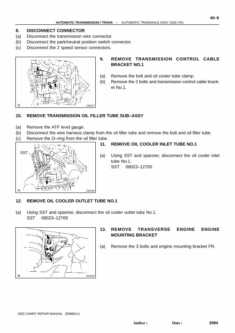
8. DISCONNECT CONNECTOR(a) Disconnect the transmission wire connector.(b) Disconnect the park/neutral position switch connector.(c) Disconnect the 2 speed sensor connectors.
9. REMOVE TRANSMISSION CONTROL CABLEBRACKET NO.1
(a) Remove the bolt and oil cooler tube clamp.(b) Remove the 2 bolts and transmission control cable brack-
et No.1.
10. REMOVE TRANSMISSION OIL FILLER TUBE SUB–ASSY
(a) Remove the ATF level gauge.(b) Disconnect the wire harness clamp from the oil filler tube and remove the bolt and oil filler tube.(c) Remove the O–ring from the oil filler tube.
11. REMOVE OIL COOLER INLET TUBE NO.1
(a) Using SST and spanner, disconnect the oil cooler inlettube No.1.SST 09023–12700
12. REMOVE OIL COOLER OUTLET TUBE NO.1
(a) Using SST and spanner, disconnect the oil cooler outlet tube No.1.SST 09023–12700
13. REMOVE TRANSVERSE ENGINE ENGINEMOUNTING BRACKET
(a) Remove the 3 bolts and engine mounting bracket FR.

C90568
D02828
C96138
C83119
40–10–AUTOMATIC TRANSMISSION / TRANS AUTOMATIC TRANSAXLE ASSY (1MZ–FE)
2085Author�: Date�:
2002 CAMRY REPAIR MANUAL (RM881U)
14. REMOVE FLYWHEEL HOUSING UNDER COVER(a) Remove the 2 bolts and flywheel housing under cover.
15. REMOVE AUTOMATIC TRANSAXLE ASSY
(a) Turn the crankshaft to gain access and remove the 6 boltswhile holding the crankshaft pulley bolt with a wrench.
(b) Remove the 8 bolts.(c) Separate and remove the automatic transaxle.
16. REMOVE TORQUE CONVERTER CLUTCH ASSY
17. INSPECT TORQUE CONVERTER CLUTCH ASSY(See page 40–20)SST 09350–32014 (09351–32010, 09351–32020)
18. INSTALL TORQUE CONVERTER CLUTCH ASSY
(a) Install the torque converter clutch to the automatic trans-axle.
(b) Using vernier calipers, measure the dimension ”A” be-tween the transaxle fitting part and the converter fittingpart of the drive plate.
C65911Dimension B
C96138
A
AA
A
A
BB
B
D02828
C90568
D25420
–AUTOMATIC TRANSMISSION / TRANS AUTOMATIC TRANSAXLE ASSY (1MZ–FE)40–11
2086Author�: Date�:
2002 CAMRY REPAIR MANUAL (RM881U)
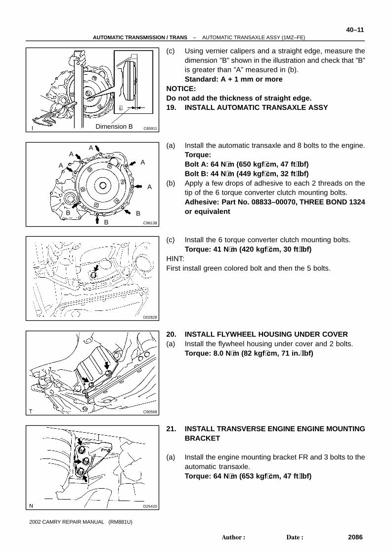
(c) Using vernier calipers and a straight edge, measure thedimension ”B” shown in the illustration and check that ”B”is greater than ”A” measured in (b).Standard: A + 1 mm or more
NOTICE:Do not add the thickness of straight edge.19. INSTALL AUTOMATIC TRANSAXLE ASSY
(a) Install the automatic transaxle and 8 bolts to the engine.Torque:Bolt A: 64 N ⋅m (650 kgf ⋅cm, 47 ft ⋅lbf)Bolt B: 44 N ⋅m (449 kgf ⋅cm, 32 ft ⋅lbf)
(b) Apply a few drops of adhesive to each 2 threads on thetip of the 6 torque converter clutch mounting bolts.Adhesive: Part No. 08833–00070, THREE BOND 1324or equivalent
(c) Install the 6 torque converter clutch mounting bolts.Torque: 41 N ⋅m (420 kgf ⋅cm, 30 ft ⋅lbf)
HINT:First install green colored bolt and then the 5 bolts.
20. INSTALL FLYWHEEL HOUSING UNDER COVER(a) Install the flywheel housing under cover and 2 bolts.
Torque: 8.0 N ⋅m (82 kgf ⋅cm, 71 in. ⋅lbf)
21. INSTALL TRANSVERSE ENGINE ENGINE MOUNTINGBRACKET
(a) Install the engine mounting bracket FR and 3 bolts to theautomatic transaxle.Torque: 64 N ⋅m (653 kgf ⋅cm, 47 ft ⋅lbf)

C83206
C92539
C92540
SST
40–12–AUTOMATIC TRANSMISSION / TRANS AUTOMATIC TRANSAXLE ASSY (1MZ–FE)
2087Author�: Date�:
2002 CAMRY REPAIR MANUAL (RM881U)
22. INSTALL TRANSMISSION OIL FILLER TUBE SUB–ASSY
(a) Coat a new O–ring with ATF, and install them to the oil filler tube.(b) Install the oil filler tube and bolt to the automatic transaxle.
Torque: 5.5 N ⋅m (56 kgf ⋅cm, 49 in. ⋅lbf)(c) Connect the wire harness clamp to the oil filler tube.(d) Install the ATF level gauge.
23. INSTALL TRANSMISSION CONTROL CABLEBRACKET NO.1
(a) Install the control cable bracket No.1 and 2 bolts.Torque: 11.8 N ⋅m (122 kgf ⋅cm, 9 ft ⋅lbf)
24. INSTALL OIL COOLER INLET TUBE NO.1
(a) Temporarily install the oil cooler outlet tube No.1.(b) Temporarily install the oil cooler inlet tube No.1.
(c) Install the oil cooler tube clamp and bolt.Torque: 5.4 N ⋅m (55 kgf ⋅cm, 48 in. ⋅lbf)
HINT:Install them so that the oil cooler tube cushion is positioned asbeing illustrated.
(d) Using SST and spanner, tighten the oil cooler inlet tubeNo.1.SST 09023–12700Torque: 34.3 N ⋅m (350 kgf ⋅cm, 25 ft ⋅lbf)
25. INSTALL OIL COOLER OUTLET TUBE NO.1
(a) Using SST and spanner, tighten the oil cooler outlet tube No.1 .SST 09023–12700Torque: 34.3 N ⋅m (350 kgf ⋅cm, 25 ft ⋅lbf)

C90567
C83204
C90565
C90566
–AUTOMATIC TRANSMISSION / TRANS AUTOMATIC TRANSAXLE ASSY (1MZ–FE)40–13
2088Author�: Date�:
2002 CAMRY REPAIR MANUAL (RM881U)
26. INSTALL STARTER ASSY
(a) Install the starter assy and 2 bolts.Torque: 37 N ⋅m (377 kgf ⋅cm, 27 ft ⋅lbf)
(b) Connect the connecter.
27. INSTALL WIRE HARNESS(a) Install the wire harness and bolt.
Torque: 25.5 N ⋅m (260 kgf ⋅cm, 19 ft ⋅lbf)
28. INSTALL WIRE HARNESS CLAMP(a) Install the 2 clamps and 2 bolts.
Torque: 8.4 N ⋅m (86 kgf ⋅cm, 74 in. ⋅lbf)(b) Connect the wire harness to the clamps.
29. INSTALL TRANSMISSION CONTROL CABLEBRACKET NO.2
(a) Install the transmission control cable bracket No.2 withthe bolt.Torque: 11.8 N ⋅m (122 kgf ⋅cm, 9 ft ⋅lbf)
30. INSTALL FRONT DRIVE SHAFT ASSY LH(See page 30–8)
31. INSTALL FRONT DRIVE SHAFT ASSY RH(See page 30–8)
32. INSTALL ENGINE ASSEMBLY WITH TRANSAXLE(See page 14–155)

400FK–01
C90566
C90565
C83204
C90567
40–14–AUTOMATIC TRANSMISSION / TRANS AUTOMATIC TRANSAXLE ASSY (2AZ–FE)
2089Author�: Date�:
2002 CAMRY REPAIR MANUAL (RM881U)
AUTOMATIC TRANSAXLE ASSY (2AZ–FE)REPLACEMENT1. REMOVE ENGINE ASSEMBLY WITH TRANSAXLE(See page 14–22)2. REMOVE FRONT DRIVE SHAFT ASSY RH
(See page 30–8)3. REMOVE FRONT DRIVE SHAFT ASSY LH
(See page 30–8)
4. REMOVE TRANSMISSION CONTROL CABLEBRACKET NO.2
(a) Remove the bolt and transmission control cable bracketNo.2.
5. REMOVE WIRE HARNESS CLAMP(a) Disconnect the wire harness from the clamps.(b) Remove the 2 bolts and 2 clamps.
6. DISCONNECT WIRE HARNESS(a) Remove the bolt and wire harness.
7. REMOVE STARTER ASSY
(a) Disconnect the connector.(b) Remove the 2 bolts and starter assy.

C92537
C92538
SST
D25420
–AUTOMATIC TRANSMISSION / TRANS AUTOMATIC TRANSAXLE ASSY (2AZ–FE)40–15
2090Author�: Date�:
2002 CAMRY REPAIR MANUAL (RM881U)
8. DISCONNECT CONNECTOR(a) Disconnect the transmission wire connector.(b) Disconnect the park/neutral position switch connector.(c) Disconnect the 2 speed sensor connectors.
9. REMOVE TRANSMISSION CONTROL CABLEBRACKET NO.1
(a) Remove the bolt and oil cooler tube clamp.(b) Remove the 2 bolts and transmission control cable brack-
et No.1.
10. REMOVE TRANSMISSION OIL FILLER TUBE SUB–ASSY
(a) Remove the ATF level gauge.(b) Disconnect the wire harness clamp from the oil filler tube and remove the bolt and oil filler tube.(c) Remove the O–ring from the oil filler tube.
11. REMOVE OIL COOLER INLET TUBE NO.1
(a) Using SST and spanner, disconnect the oil cooler inlettube No.1.SST 09023–12700
12. REMOVE OIL COOLER OUTLET TUBE NO.1
(a) Using SST and spanner, disconnect the oil cooler outlet tube No.1.SST 09023–12700
13. REMOVE TRANSVERSE ENGINE ENGINEMOUNTING BRACKET
(a) Remove the 3 bolts and engine mounting bracket FR.

D25407
D25408
C96139
C83051
40–16–AUTOMATIC TRANSMISSION / TRANS AUTOMATIC TRANSAXLE ASSY (2AZ–FE)
2091Author�: Date�:
2002 CAMRY REPAIR MANUAL (RM881U)
14. REMOVE FLYWHEEL HOUSING UNDER COVER
(a) Remove the flywheel housing under cover.
15. REMOVE AUTOMATIC TRANSAXLE ASSY
(a) Remove the 6 bolts while holding the crankshaft pulleybolt with a wrench.
(b) Remove the 9 bolts.(c) Separate and remove the automatic transaxle.
16. REMOVE TORQUE CONVERTER CLUTCH ASSY
17. INSPECT TORQUE CONVERTER CLUTCH ASSY(See page 40–20)SST 09350–32014 (09351–32010, 09351–32020)
18. INSTALL TORQUE CONVERTER CLUTCH ASSY
(a) Install the torque converter clutch to the automatic trans-axle.
(b) Using vernier calipers, measure the dimension ”A” be-tween the transaxle fitting part and the converter fittingpart of the drive plate.

C65911Dimension B
C96139
A A
A
B
B
CC C
C
D25408
D25407
D25420
–AUTOMATIC TRANSMISSION / TRANS AUTOMATIC TRANSAXLE ASSY (2AZ–FE)40–17
2092Author�: Date�:
2002 CAMRY REPAIR MANUAL (RM881U)
(c) Using vernier calipers and a straight edge, measure thedimension ”B” shown in the illustration and check that ”B”is greater than ”A” measured in (b).Standard: A + 1 mm or more
NOTICE:Do not add the thickness of straight edge.19. INSTALL AUTOMATIC TRANSAXLE ASSY
(a) Install the automatic transaxle and 9 bolts to the engine.Torque:Bolt A: 64 N ⋅m (650 kgf ⋅cm, 47 ft ⋅lbf)Bolt B: 46 N ⋅m (470 kgf ⋅cm, 34 ft ⋅lbf)Bolt C: 44 N ⋅m (449 kgf ⋅cm, 32 ft ⋅lbf)
(b) Apply a few drops of adhesive to each 2 threads on thetip of the 6 torque converter clutch mounting bolts.Adhesive: Part No. 08833–00070, THREE BOND 1324or equivalent
(c) Install the 6 torque converter clutch mounting bolts.Torque: 41 N ⋅m (420 kgf ⋅cm, 30 ft ⋅lbf)
HINT:First install green colored bolt and then the other 5 bolts.
20. INSTALL FLYWHEEL HOUSING UNDER COVER
(a) Install the flywheel housing under cover.
21. INSTALL TRANSVERSE ENGINE ENGINE MOUNTINGBRACKET
(a) Install the engine mounting bracket FR and 3 bolts to theautomatic transaxle.Torque: 64 N ⋅m (653 kgf ⋅cm, 47 ft ⋅lbf)

C83206
C92539
C92540
SST
40–18–AUTOMATIC TRANSMISSION / TRANS AUTOMATIC TRANSAXLE ASSY (2AZ–FE)
2093Author�: Date�:
2002 CAMRY REPAIR MANUAL (RM881U)
22. INSTALL TRANSMISSION OIL FILLER TUBE SUB–ASSY
(a) Coat a new O–ring with ATF, and install them to the oil filler tube.(b) Install the oil filler tube and bolt to the automatic transaxle.
Torque: 5.5 N ⋅m (56 kgf ⋅cm, 49 in. ⋅lbf)(c) Connect the wire harness clamp to the oil filler tube.(d) Install the ATF level gauge.
23. INSTALL TRANSMISSION CONTROL CABLEBRACKET NO.1
(a) Install the control cable bracket No.1 and 2 bolts.Torque: 11.8 N ⋅m (122 kgf ⋅cm, 9 ft ⋅lbf)
24. INSTALL OIL COOLER INLET TUBE NO.1
(a) Temporarily install the oil cooler outlet tube No.1.(b) Temporarily install the oil cooler inlet tube No.1.
(c) Install the oil cooler tube clamp and bolt.Torque: 5.4 N ⋅m (56 kgf ⋅cm, 49 in. ⋅lbf)
HINT:Install them so that the oil cooler tube cushion is positioned asbeing illustrated.
(d) Using SST and spanner, tighten the oil cooler inlet tubeNo.1.SST 09023–12700Torque: 34.3 N ⋅m (350 kgf ⋅cm, 25 ft ⋅lbf)
25. INSTALL OIL COOLER OUTLET TUBE NO.1
(a) Using SST and spanner, tighten the oil cooler outlet tube No.1.SST 09023–12700Torque: 34.3 N ⋅m (350 kgf ⋅cm, 25 ft ⋅lbf)

C90567
C83204
C90565
C90566
–AUTOMATIC TRANSMISSION / TRANS AUTOMATIC TRANSAXLE ASSY (2AZ–FE)40–19
2094Author�: Date�:
2002 CAMRY REPAIR MANUAL (RM881U)
26. INSTALL STARTER ASSY
(a) Install the starter assy and 2 bolts.Torque: 37 N ⋅m (377 kgf ⋅cm, 27 ft ⋅lbf)
(b) Connect the connecter.
27. INSTALL WIRE HARNESS(a) Install the wire harness and bolt.
Torque: 25.5 N ⋅m (260 kgf ⋅cm, 19 ft ⋅lbf)
28. INSTALL WIRE HARNESS CLAMP(a) Install the 2 clamps and 2 bolts.
Torque: 8.4 N ⋅m (86 kgf ⋅cm, 74 in. ⋅lbf)(b) Connect the wire harness to the clamps.
29. INSTALL TRANSMISSION CONTROL CABLEBRACKET NO.2
(a) Install the transmission control cable bracket No.2 andbolt.Torque: 11.8 N ⋅m (122 kgf ⋅cm, 9 ft ⋅lbf)
30. INSTALL FRONT DRIVE SHAFT ASSY LH(See page 30–8)
31. INSTALL FRONT DRIVE SHAFT ASSY RH(See page 30–8)
32. INSTALL ENGINE ASSEMBLY WITH TRANSAXLE(See page 14–22)

40063–02
AT0953
SST
AT3306
Hold
Turn
Lock
Free
D25367
Sample showing minimum amount ofpowders in ATF
Actual Size
40–20–AUTOMATIC TRANSMISSION / TRANS TORQUE CONVERTER CLUTCH AND DRIVE PLATE
2095Author�: Date�:
2002 CAMRY REPAIR MANUAL (RM881U)
TORQUE CONVERTER CLUTCH AND DRIVE PLATEINSPECTION
1. INSPECT TORQUE CONVERTER CLUTCH ASSY
(a) Inspect the one–way clutch.(1) Set SST into the inner race of the one–way clutch.SST 09350–32014 (09351–32010)(2) Install SST so that it fits in the notch of the converter
hub and outer race of the one–way clutch.SST 09350–32014 (09351–32020)
(3) With the torque converter clutch setting up on itsside, check that the one–way clutch locks when it isturned counterclockwise, and rotates clockwisesmoothly.
If necessary, clean the converter and retest the one–wayclutch.Replace the converter if the one–way clutch still fails the test.
(b) Determine the condition of the torque converter clutchassy.(1) If the inspection result of the torque converter clutch
assy meets the following item, replace the torqueconverter clutch.
Malfunction item:Any metallic sound is heard from the torque convert-er clutch during stall test or when the shift lever is inneutral position.One–way clutch is free or locked in both directions.Fine powders exceeding the sample limit is identifiedin ATF. (See the sample.)
HINT:The sample shows the auto fluid of approx. 0.25 liters (0.26 USqts, 0.22 Imp. qts) that is taken out from the removed torqueconverter clutch(c) Exchange the ATF in the torque converter clutch.
(1) If the ATF is discolored and/or has a foul odor, com-pletely stir the ATF in the torque converter clutchand drain the ATF with the torque converter facingto up.

C11090
D25368
OK NG
The Bottom is Damaged
C81014
–AUTOMATIC TRANSMISSION / TRANS TORQUE CONVERTER CLUTCH AND DRIVE PLATE40–21
2096Author�: Date�:
2002 CAMRY REPAIR MANUAL (RM881U)
(d) Clean and check the oil cooler and oil pipe line.(1) If the torque converter clutch is inspected or the ATF
is exchanged, clean the oil cooler and oil pipe line.HINT:� Spray compressed air of 196 kPa (2 kgf/cm2, 28 psi) from
the inlet hose.� If plenty of fine powders are identified in the ATF, add new
ATF using a bucket pump and clean it again.(2) If the ATF is cloudy, inspect the oil cooler (radiator).
(e) Prevent deformation of the torque converter clutch anddamage to the oil pump gear.(1) When any marks due to interference are found on
the end of the bolt for the torque converter clutchand on the bottom of the bolt hole, replace the boltand the torque converter clutch.
(2) All of the bolts must be the same length.(3) The bolts with washers must be used.
2. INSPECT DRIVE PLATE & RING GEAR SUB–ASSY
(a) Set up a dial indicator and measure the drive plate runout.(b) Check the damage of the ring gear.
Maximum runout: 0.20 mm (0.0079 in.)If the runout is not within the specification or ring gear is dam-aged, replace the drive plate.
4005U–02
C90569
C90570
C90570
40–22–AUTOMATIC TRANSMISSION / TRANS TRANSMISSION REVOLUTION SENSOR
2097Author�: Date�:
2002 CAMRY REPAIR MANUAL (RM881U)
TRANSMISSION REVOLUTION SENSORREPLACEMENT1. REMOVE BATTERY2. REMOVE ENGINE COVER SUB–ASSY NO.1
3. REMOVE AIR CLEANER ASSY
4. REMOVE AIR CLEANER HOSE NO.1
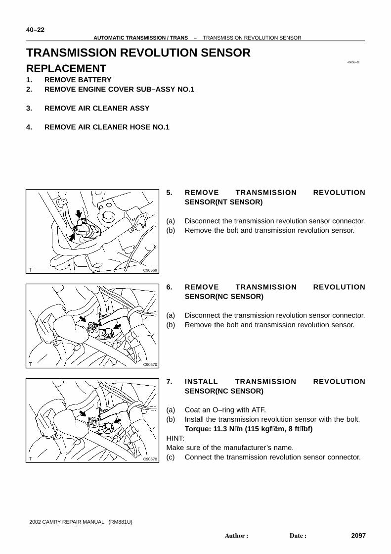
5. REMOVE TRANSMISSION REVOLUTIONSENSOR(NT SENSOR)
(a) Disconnect the transmission revolution sensor connector.(b) Remove the bolt and transmission revolution sensor.
6. REMOVE TRANSMISSION REVOLUTIONSENSOR(NC SENSOR)
(a) Disconnect the transmission revolution sensor connector.(b) Remove the bolt and transmission revolution sensor.
7. INSTALL TRANSMISSION REVOLUTIONSENSOR(NC SENSOR)
(a) Coat an O–ring with ATF.(b) Install the transmission revolution sensor with the bolt.
Torque: 11.3 N ⋅m (115 kgf ⋅cm, 8 ft ⋅lbf)HINT:Make sure of the manufacturer’s name.(c) Connect the transmission revolution sensor connector.
C90569
–AUTOMATIC TRANSMISSION / TRANS TRANSMISSION REVOLUTION SENSOR40–23
2098Author�: Date�:
2002 CAMRY REPAIR MANUAL (RM881U)
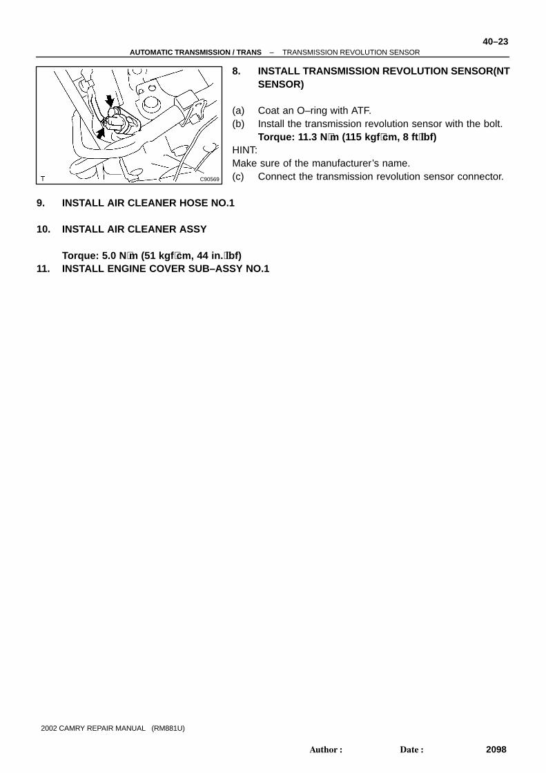
8. INSTALL TRANSMISSION REVOLUTION SENSOR(NTSENSOR)
(a) Coat an O–ring with ATF.(b) Install the transmission revolution sensor with the bolt.
Torque: 11.3 N ⋅m (115 kgf ⋅cm, 8 ft ⋅lbf)HINT:Make sure of the manufacturer’s name.(c) Connect the transmission revolution sensor connector.
9. INSTALL AIR CLEANER HOSE NO.1
10. INSTALL AIR CLEANER ASSY
Torque: 5.0 N ⋅m (51 kgf ⋅cm, 44 in. ⋅lbf)11. INSTALL ENGINE COVER SUB–ASSY NO.1

40060–02
C90569
C90570
C90570
40–24–AUTOMATIC TRANSMISSION / TRANS SPEED SENSOR
2099Author�: Date�:
2002 CAMRY REPAIR MANUAL (RM881U)
SPEED SENSORREPLACEMENT1. REMOVE BATTERY2. REMOVE ENGINE COVER SUB–ASSY NO.1
3. REMOVE AIR CLEANER ASSY
4. REMOVE AIR CLEANER HOSE NO.1
5. REMOVE SPEED SENSOR(NT SENSOR)
(a) Disconnect the speed sensor connector.(b) Remove the bolt and speed sensor.
6. REMOVE SPEED SENSOR(NC SENSOR)
(a) Disconnect the speed sensor connector.(b) Remove the bolt and speed sensor.
7. INSTALL SPEED SENSOR(NC SENSOR)
(a) Coat an O–ring with ATF.(b) Install the speed sensor with the bolt.
Torque: 11.3 N ⋅m (115 kgf ⋅cm, 8 ft ⋅lbf)HINT:Make sure of the manufacturer’s name.(c) Connect the speed sensor connector.

C90569
–AUTOMATIC TRANSMISSION / TRANS SPEED SENSOR40–25
2100Author�: Date�:
2002 CAMRY REPAIR MANUAL (RM881U)
8. INSTALL SPEED SENSOR(NT SENSOR)
(a) Coat an O–ring with ATF.(b) Install the speed sensor with the bolt.
Torque: 11.3 N ⋅m (115 kgf ⋅cm, 8 ft ⋅lbf)HINT:Make sure of the manufacturer’s name.(c) Connect the speed sensor connector.
9. INSTALL AIR CLEANER HOSE NO.1
10. INSTALL AIR CLEANER ASSY
Torque: 5.0 N ⋅m (51 kgf ⋅cm, 44 in. ⋅lbf)11. INSTALL ENGINE COVER SUB–ASSY NO.1

4005V–02
C83111
AT0103
D25591
C50009
40–26–AUTOMATIC TRANSMISSION / TRANS TRANSMISSION WIRE
2101Author�: Date�:
2002 CAMRY REPAIR MANUAL (RM881U)
TRANSMISSION WIREREPLACEMENT1. REMOVE ENGINE UNDER COVER LH
2. DRAIN AUTOMATIC TRANSAXLE FLUID(a) Remove the drain plug and gasket, and drain ATF.(b) Install a new gasket and drain plug.
Torque: 49 N ⋅m (500 kgf ⋅cm, 36 ft ⋅lbf)
3. REMOVE AUTOMATIC TRANSAXLE OIL PANSUB–ASSY
(a) Remove the 18 bolts, oil pan and gasket.NOTICE:Some fluid will remain in the oil pan. Remove all pan bolts,and carefully remove the oil pan assembly.(b) Remove the 2 magnets from the oil pan.
(c) Examine particles in pan.(1) Remove the magnets and use them to collect any
steel chips. Look carefully at the chips and particlesin the pan and the magnet to anticipate what typeof wear you will find in the transaxle.Steel (magnetic): bearing, gear and plate wearBrass (non–magnetic): bearing wear
4. DISCONNECT TRANSMISSION WIRE
(a) Disconnect the 5 shift solenoid valve connectors.(b) Remove the bolt and lock plate, and disconnect the ATF
temperature sensor.
5. REMOVE TRANSMISSION WIRE
(a) Disconnect the transmission wire connector.(b) Remove the bolt and transmission wire.

D03636
C50009
D25591
D25674
C83111
–AUTOMATIC TRANSMISSION / TRANS TRANSMISSION WIRE40–27
2102Author�: Date�:
2002 CAMRY REPAIR MANUAL (RM881U)
6. INSTALL TRANSMISSION WIRE
(a) Coat a O–ring of the transmission wire connector withATF.
(b) Install the transmission wire.
(c) Install the bolt.Torque: 5.4 N ⋅m (55 kgf ⋅cm, 48 in. ⋅lbf)
7. CONNECT TRANSMISSION WIRE
(a) Coat a O–ring of the ATF temperature sensor with ATF.(b) Install the ATF temperature sensor with the lock plate and
bolt.Torque: 6.6 N ⋅m (67 kgf ⋅cm, 58 in. ⋅lbf)
(c) Connect the 5 shift solenoid valve connectors.
8. INSTALL AUTOMATIC TRANSAXLE OIL PANSUB–ASSY
(a) Install the 2 magnets in the oil pan.(b) Apply seal packing or equivalent to 18 bolts.
Seal packing:THREE BOND 2430 or equivalent
(c) Install a new gasket, oil pan and 18 bolts to the transaxlecase.Torque: 7.8 N ⋅m (80 kgf ⋅cm, 69 in. ⋅lbf)
NOTICE:Because the bolts should be seal bolts, apply seal packingto bolts and tighten them within 10 minutes after applica-tion.

40–28–AUTOMATIC TRANSMISSION / TRANS TRANSMISSION WIRE
2103Author�: Date�:
2002 CAMRY REPAIR MANUAL (RM881U)
9. ADD AUTOMATIC TRANSAXLE FLUID10. INSPECT AUTOMATIC TRANSAXLE FLUID(See page 40–1)11. INSTALL ENGINE UNDER COVER LH

40064–02
C83111
AT0103
D25591
D09179
–AUTOMATIC TRANSMISSION / TRANS TRANSMISSION VALVE BODY ASSY40–29
2104Author�: Date�:
2002 CAMRY REPAIR MANUAL (RM881U)
TRANSMISSION VALVE BODY ASSYREPLACEMENT1. REMOVE ENGINE UNDER COVER RH
2. DRAIN AUTOMATIC TRANSAXLE FLUID(a) Remove the drain plug and gasket, and drain ATF.(b) Install a new gasket and drain plug.
Torque: 49 N ⋅m (500 kgf ⋅cm, 36 ft ⋅lbf)
3. REMOVE AUTOMATIC TRANSAXLE OIL PANSUB–ASSY
(a) Remove the 18 bolts, oil pan and gasket.NOTICE:Some fluid will remain in the oil pan. Remove all pan bolts,and carefully remove the oil pan assembly.(b) Remove the 2 magnets from the oil pan.
(c) Examine particles in pan.(1) Remove the magnets and use them to collect any
steel chips. Look carefully at the chips and particlesin the pan and the magnet to anticipate what typeof wear you will find in the transaxle.Steel (magnetic): bearing, gear and plate wearBrass (non–magnetic): bearing wear
4. DISCONNECT TRANSMISSION WIRE
(a) Disconnect the 5 shift solenoid valve connectors.(b) Remove the bolt and lock plate, and disconnect the ATF
temperature sensor.
5. REMOVE VALVE BODY OIL STRAINER ASSY
(a) Remove the 3 bolts and oil strainer.NOTICE:Be careful as some fluid will come out with the oil strainer.

C69150
D03553
C50017
D02938
D02938
A
A B B
B
40–30–AUTOMATIC TRANSMISSION / TRANS TRANSMISSION VALVE BODY ASSY
2105Author�: Date�:
2002 CAMRY REPAIR MANUAL (RM881U)
(b) Remove the O–ring from the oil strainer.
6. REMOVE TRANSMISSION VALVE BODY ASSY
(a) Support the valve body assy and remove the 17 bolts andthe valve body assy.
NOTICE:Be careful not to drop the check valve body, spring and ac-cumulator piston.
(b) Remove the check ball body and spring.
(c) Remove the 5 bolts and 5 shift solenoid valves.
7. INSTALL TRANSMISSION VALVE BODY ASSY
(a) Install the 5 shift solenoid valves with the 5 bolts.Torque:Bolt A: 6.6 N·m (67 kgf·cm, 58 in. ⋅lbf)Bolt B: 10.8 N·m (110 kgf·cm, 8 ft ·lbf)Bolt length:Bolt A: 12 mm (0.47 in.)Bolt B: 45 mm (1.77 in.)

C50017
D03553
B
C
A
A
A
B
B �
CC�
C69150
D09179
–AUTOMATIC TRANSMISSION / TRANS TRANSMISSION VALVE BODY ASSY40–31
2106Author�: Date�:
2002 CAMRY REPAIR MANUAL (RM881U)
(b) Install the spring and check ball body.
(c) Align the groove of the manual valve with the pin of lever.(d) Install the 17 bolts.
Torque: 10.8 N ⋅m (110 kgf ⋅cm, 8 ft ⋅lbf)NOTICE:� Push the valve body against the accumulator piston
spring and the check ball body to install it.� Tighten those bolts marked by � in the illustration
first temporarily because they are positioning bolts.Bolt length:Bolt A: 25 mm (0.984 in.)Bolt B: 41 mm (1.614 in.)Bolt C: 45 mm (1.771 in.)
8. INSTALL VALVE BODY OIL STRAINER ASSY
(a) Coat a new O–ring with ATF.(b) Install the O–ring to the oil strainer.
(c) Install the oil strainer with the 3 bolts.Torque: 10.8 N ⋅m (110 kgf ⋅cm, 8 ft ⋅lbf)

D25591
D25674
C83111
40–32–AUTOMATIC TRANSMISSION / TRANS TRANSMISSION VALVE BODY ASSY
2107Author�: Date�:
2002 CAMRY REPAIR MANUAL (RM881U)
9. INSTALL TRANSMISSION WIRE
(a) Coat an O–ring with ATF.(b) Install the ATF temperature sensor with the lock plate and
bolt.Torque: 6.6 N ⋅m (67 kgf ⋅cm, 58 in. ⋅lbf)
(c) Connect the 5 shift solenoid valve connectors.
10. INSTALL AUTOMATIC TRANSAXLE OIL PANSUB–ASSY
(a) Install the 2 magnets in the oil pan.(b) Apply seal packing or equivalent to 18 bolts.
Seal packing:THREE BOND 2430 or equivalent
(c) Install a new gasket, oil pan and 18 bolts to the transaxlecase.Torque: 7.8 N ⋅m (80 kgf ⋅cm, 69 in. ⋅lbf)
NOTICE:Because the bolts should be seal bolts, apply seal packingto bolts and tighten them within 10 minutes after applica-tion.
11. ADD AUTOMATIC TRANSAXLE FLUID12. INSPECT AUTOMATIC TRANSAXLE FLUID(See page 40–1)

40065–02
D25827
SST
D25828
SST
D25829
SST
–AUTOMATIC TRANSMISSION / TRANS FRONT DIFFERENTIAL OIL SEAL (U241E)40–33
2108Author�: Date�:
2002 CAMRY REPAIR MANUAL (RM881U)
FRONT DIFFERENTIAL OIL SEAL (U241E)REPLACEMENT1. REMOVE FRONT WHEEL2. REMOVE ENGINE UNDER COVER RH
3. REMOVE ENGINE UNDER COVER LH
4. DRAIN AUTOMATIC TRANSAXLE FLUID(a) Remove the drain plug and gasket, and drain ATF.(b) Install a new gasket and drain plug.
Torque: 49 N ⋅m (500 kgf ⋅cm, 36 ft ⋅lbf)5. REMOVE FRONT DRIVE SHAFT ASSY RH
(See page 30–8)6. REMOVE FRONT DRIVE SHAFT ASSY LH
(See page 30–8)
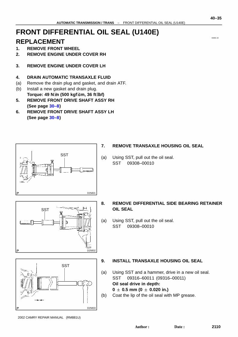
7. REMOVE TRANSAXLE HOUSING OIL SEAL
(a) Using SST, pull out the oil seal.SST 09308–00010
8. REMOVE DIFFERENTIAL SIDE BEARING RETAINEROIL SEAL
(a) Using SST, pull out the oil seal.SST 09308–00010
9. INSTALL TRANSAXLE HOUSING OIL SEAL
(a) Using SST and a hammer, drive in a new oil seal.SST 09316–60011 (09316–00011)Oil seal drive in depth:0 � 0.5 mm (0 � 0.020 in.)
(b) Coat the lip of the oil seal with MP grease.
D25830SST
40–34–AUTOMATIC TRANSMISSION / TRANS FRONT DIFFERENTIAL OIL SEAL (U241E)
2109Author�: Date�:
2002 CAMRY REPAIR MANUAL (RM881U)
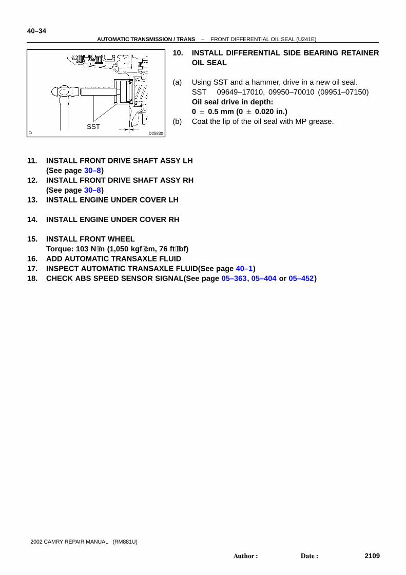
10. INSTALL DIFFERENTIAL SIDE BEARING RETAINEROIL SEAL
(a) Using SST and a hammer, drive in a new oil seal.SST 09649–17010, 09950–70010 (09951–07150)Oil seal drive in depth:0 � 0.5 mm (0 � 0.020 in.)
(b) Coat the lip of the oil seal with MP grease.
11. INSTALL FRONT DRIVE SHAFT ASSY LH(See page 30–8)
12. INSTALL FRONT DRIVE SHAFT ASSY RH(See page 30–8)
13. INSTALL ENGINE UNDER COVER LH
14. INSTALL ENGINE UNDER COVER RH
15. INSTALL FRONT WHEELTorque: 103 N ⋅m (1,050 kgf ⋅cm, 76 ft ⋅lbf)
16. ADD AUTOMATIC TRANSAXLE FLUID17. INSPECT AUTOMATIC TRANSAXLE FLUID(See page 40–1)18. CHECK ABS SPEED SENSOR SIGNAL(See page 05–363, 05–404 or 05–452)
40066–02
D25831
SST
D25832
SST
D25833
SST
–AUTOMATIC TRANSMISSION / TRANS FRONT DIFFERENTIAL OIL SEAL (U140E)40–35
2110Author�: Date�:
2002 CAMRY REPAIR MANUAL (RM881U)
FRONT DIFFERENTIAL OIL SEAL (U140E)REPLACEMENT1. REMOVE FRONT WHEEL2. REMOVE ENGINE UNDER COVER RH
3. REMOVE ENGINE UNDER COVER LH
4. DRAIN AUTOMATIC TRANSAXLE FLUID(a) Remove the drain plug and gasket, and drain ATF.(b) Install a new gasket and drain plug.
Torque: 49 N ⋅m (500 kgf ⋅cm, 36 ft ⋅lbf)5. REMOVE FRONT DRIVE SHAFT ASSY RH
(See page 30–8)6. REMOVE FRONT DRIVE SHAFT ASSY LH
(See page 30–8)
7. REMOVE TRANSAXLE HOUSING OIL SEAL
(a) Using SST, pull out the oil seal.SST 09308–00010
8. REMOVE DIFFERENTIAL SIDE BEARING RETAINEROIL SEAL
(a) Using SST, pull out the oil seal.SST 09308–00010
9. INSTALL TRANSAXLE HOUSING OIL SEAL
(a) Using SST and a hammer, drive in a new oil seal.SST 09316–60011 (09316–00011)Oil seal drive in depth:0 � 0.5 mm (0 � 0.020 in.)
(b) Coat the lip of the oil seal with MP grease.
D25834
SST
40–36–AUTOMATIC TRANSMISSION / TRANS FRONT DIFFERENTIAL OIL SEAL (U140E)
2111Author�: Date�:
2002 CAMRY REPAIR MANUAL (RM881U)
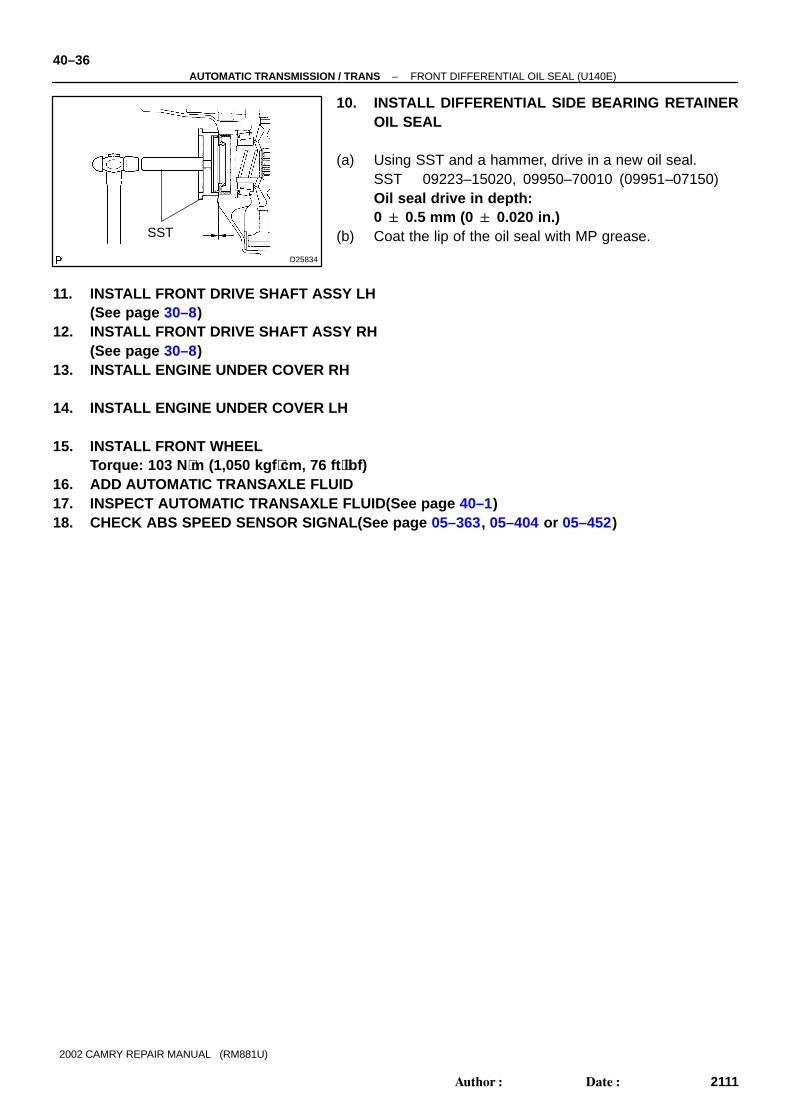
10. INSTALL DIFFERENTIAL SIDE BEARING RETAINEROIL SEAL
(a) Using SST and a hammer, drive in a new oil seal.SST 09223–15020, 09950–70010 (09951–07150)Oil seal drive in depth:0 � 0.5 mm (0 � 0.020 in.)
(b) Coat the lip of the oil seal with MP grease.
11. INSTALL FRONT DRIVE SHAFT ASSY LH(See page 30–8)
12. INSTALL FRONT DRIVE SHAFT ASSY RH(See page 30–8)
13. INSTALL ENGINE UNDER COVER RH
14. INSTALL ENGINE UNDER COVER LH
15. INSTALL FRONT WHEELTorque: 103 N ⋅m (1,050 kgf ⋅cm, 76 ft ⋅lbf)
16. ADD AUTOMATIC TRANSAXLE FLUID17. INSPECT AUTOMATIC TRANSAXLE FLUID(See page 40–1)18. CHECK ABS SPEED SENSOR SIGNAL(See page 05–363, 05–404 or 05–452)

40067–02
C63995IG ESTP
–AUTOMATIC TRANSMISSION / TRANS SHIFT LOCK SYSTEM40–37
2112Author�: Date�:
2002 CAMRY REPAIR MANUAL (RM881U)
SHIFT LOCK SYSTEMON–VEHICLE INSPECTION1. CHECK SHIFT LOCK OPERATION(a) Shift the shift lever to P position.(b) Turn the ignition switch to LOCK.(c) Check that the shift lever cannot be shifted to any other positions other than P.(d) Turn the ignition switch to ON, depress the brake pedal and check that the shift lever can be shifted
to any other positions.2. CHECK SHIFT LOCK RELEASE BUTTON OPERATION(a) Using a screwdriver, remove the shift lock release button cover.(b) When operating the shift lever with the shift lock release button pressed and the ignition key in ACC
or ON, check that the lever can be shifted to any other position.3. CHECK KEY INTERLOCK OPERATION(a) Turn the ignition switch to ON.(b) Depress the brake pedal and shift the shift lever to any other positions other than P.(c) Check that the ignition key cannot be turned to LOCK.(d) Shift the shift lever to P position, turn the ignition key to LOCK and check that the ignition key can be
removed.
4. INSPECT SHIFT LOCK CONTROL SWITCH(a) Using a voltmeter, measure the voltage at each terminal.HINT:Do not disconnect the shift lock control unit connector.
Terminal Measuring Condition Voltage (V)
5 (IG) – 1 (E) Ignition switch ON 10 – 14
5 (IG) – 1 (E) Ignition switch OFF 0
3 (STP) – 1 (E) Depress brake pedal 10 – 14
3 (STP) – 1 (E) Release brake pedal 0

C63995
E
40–38–AUTOMATIC TRANSMISSION / TRANS SHIFT LOCK SYSTEM
2113Author�: Date�:
2002 CAMRY REPAIR MANUAL (RM881U)
(b) Using an ohmmeter, measure the resistance at terminalE (1) and body ground.
Terminal Measuring Condition Specified Value
1 (E) – Body ground Always Continuity

400FL–01
C90600
C92346
–AUTOMATIC TRANSMISSION / TRANS FLOOR SHIFT ASSY40–39
2114Author�: Date�:
2002 CAMRY REPAIR MANUAL (RM881U)
FLOOR SHIFT ASSYOVERHAUL1. REMOVE CONSOLE PANEL UPPER REAR
(See page 71–12)2. REMOVE CONSOLE BOX CARPET
3. REMOVE RR CONSOLE BOX(See page 71–12)4. REMOVE INSTRUMENT PANEL CUP HOLDER TRAY(W/O ASHTRAY)
(See page 71–12)5. REMOVE INSTRUMENT PANEL ASH RECEPTACLE ASSY(W/ ASHTRAY)
(See page 71–12)6. REMOVE CONSOLE PANEL UPPER
(See page 71–12)7. REMOVE CONSOLE BOX FRONT
(See page 71–12)8. REMOVE AIR DUCT REAR NO.1
(See page 71–12)9. REMOVE AIR DUCT REAR NO.2
(See page 71–12)10. REMOVE CONSOLE BOX DUCT NO.1
(See page 71–12)
11. DISCONNECT FLOOR SHIFT PARKING LOCK CABLEASSY
(a) Disconnect the parking lock cable from the transmissionfloor shift assy.
12. DISCONNECT FLOOR SHIFT CABLE TRANSMISSIONCONTROL SHIFT
(a) Disconnect the floor shift cable from the transmissionfloor shift assy.
13. REMOVE FLOOR SHIFT ASSY(a) Disconnect the shift lock control computer connector.(b) Disconnect the transmission control switch connector.

C90589
C90590
C90591
C90592
40–40–AUTOMATIC TRANSMISSION / TRANS FLOOR SHIFT ASSY
2115Author�: Date�:
2002 CAMRY REPAIR MANUAL (RM881U)
(c) Remove the 4 bolts and transmission floor shift assy.
14. REMOVE INDICATOR LAMP WIRE SUB–ASSY
(a) Releasing the lock by pressing the slick, disconnect theindicator lamp wire connector from the shift lever plate.
(b) Disconnect the indicator lamp from the position indicatorhousing.
(c) Using a screwdriver, release the stopper of the connector.(d) Using a small screwdriver, disengage the locking lug of
the terminals 3 and 4, and pull the terminals out from therear.
(e) Disconnect the wire harness from the clamps, and re-move the indicator lamp wire.
(f) Remove the indicator lamp cap and indicator lamp bulbfrom the indicator lamp wire sub–assy.
15. REMOVE FLOOR SHIFT SHIFT LEVER KNOBSUB–ASSY
(a) Lower the position indicator slide cover.(b) Remove the 2 screws and shift lever knob from the shift
lever.
16. REMOVE POSITION INDICATOR SLIDE COVER
(a) Remove the position indicator slide cover from the shift lever.

C90593
C90594
C90595
C90596
–AUTOMATIC TRANSMISSION / TRANS FLOOR SHIFT ASSY40–41
2116Author�: Date�:
2002 CAMRY REPAIR MANUAL (RM881U)
17. REMOVE TRANSMISSION CONTROL SWITCH
(a) Using a screwdriver, remove the transmission controlswitch from the shift lever knob.
18. REMOVE SHIFT LEVER KNOB BUTTON
(a) Using a screwdriver, release the claw and remove theshift lever knob button
(b) Remove the compression spring.
19. REMOVE SHIFT LOCK RELEASE BUTTON COVER
(a) Using a screwdriver, remove the shift lock release buttoncover.
20. REMOVE POSITION INDICATOR HOUSING UPPER
(a) Using a screwdriver, release the 4 claws and remove theposition indicator housing upper.
21. REMOVE POSITION INDICATOR HOUSING COVER
22. REMOVE POSITION INDICATOR SLIDE COVER
C90597
C90598
C90599
C90599
40–42–AUTOMATIC TRANSMISSION / TRANS FLOOR SHIFT ASSY
2117Author�: Date�:
2002 CAMRY REPAIR MANUAL (RM881U)
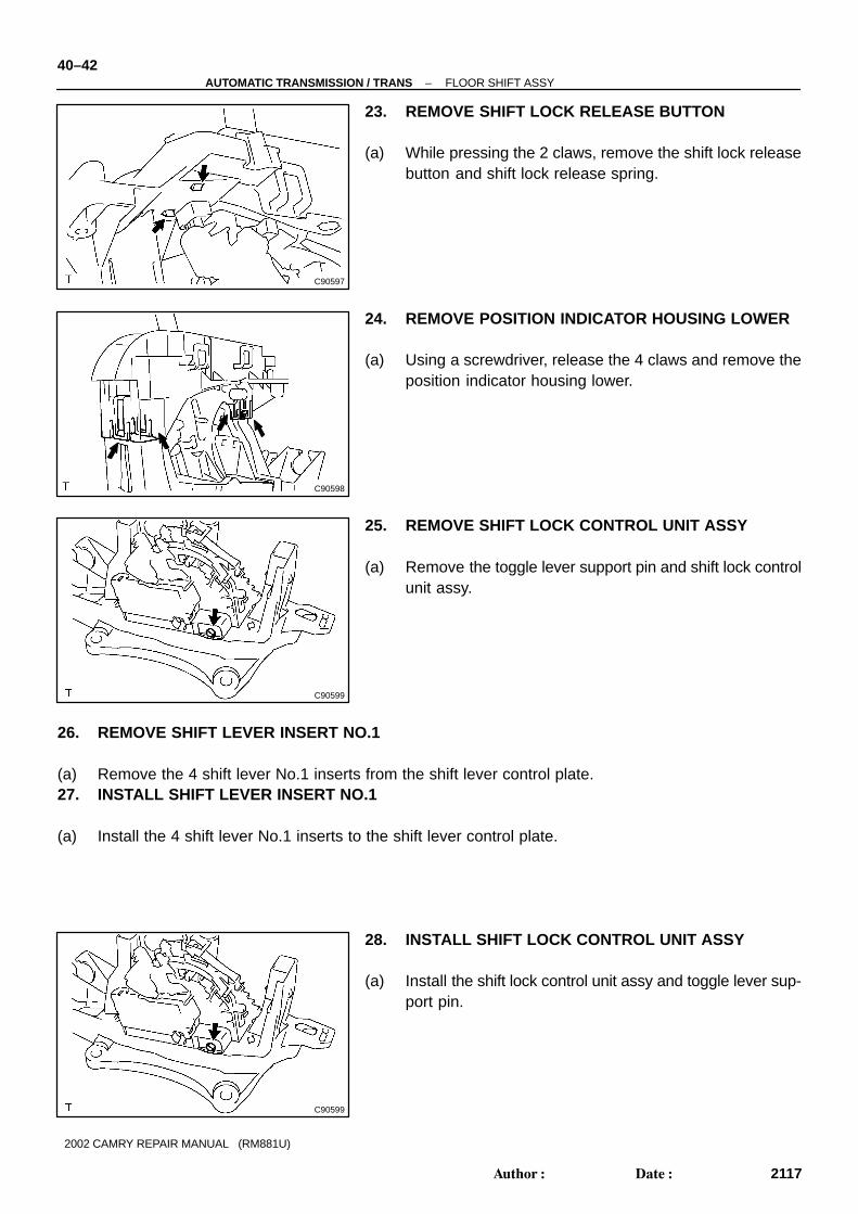
23. REMOVE SHIFT LOCK RELEASE BUTTON
(a) While pressing the 2 claws, remove the shift lock releasebutton and shift lock release spring.
24. REMOVE POSITION INDICATOR HOUSING LOWER
(a) Using a screwdriver, release the 4 claws and remove theposition indicator housing lower.
25. REMOVE SHIFT LOCK CONTROL UNIT ASSY
(a) Remove the toggle lever support pin and shift lock controlunit assy.
26. REMOVE SHIFT LEVER INSERT NO.1
(a) Remove the 4 shift lever No.1 inserts from the shift lever control plate.27. INSTALL SHIFT LEVER INSERT NO.1
(a) Install the 4 shift lever No.1 inserts to the shift lever control plate.
28. INSTALL SHIFT LOCK CONTROL UNIT ASSY
(a) Install the shift lock control unit assy and toggle lever sup-port pin.
C90598
C90601
C90596
C90595
–AUTOMATIC TRANSMISSION / TRANS FLOOR SHIFT ASSY40–43
2118Author�: Date�:
2002 CAMRY REPAIR MANUAL (RM881U)
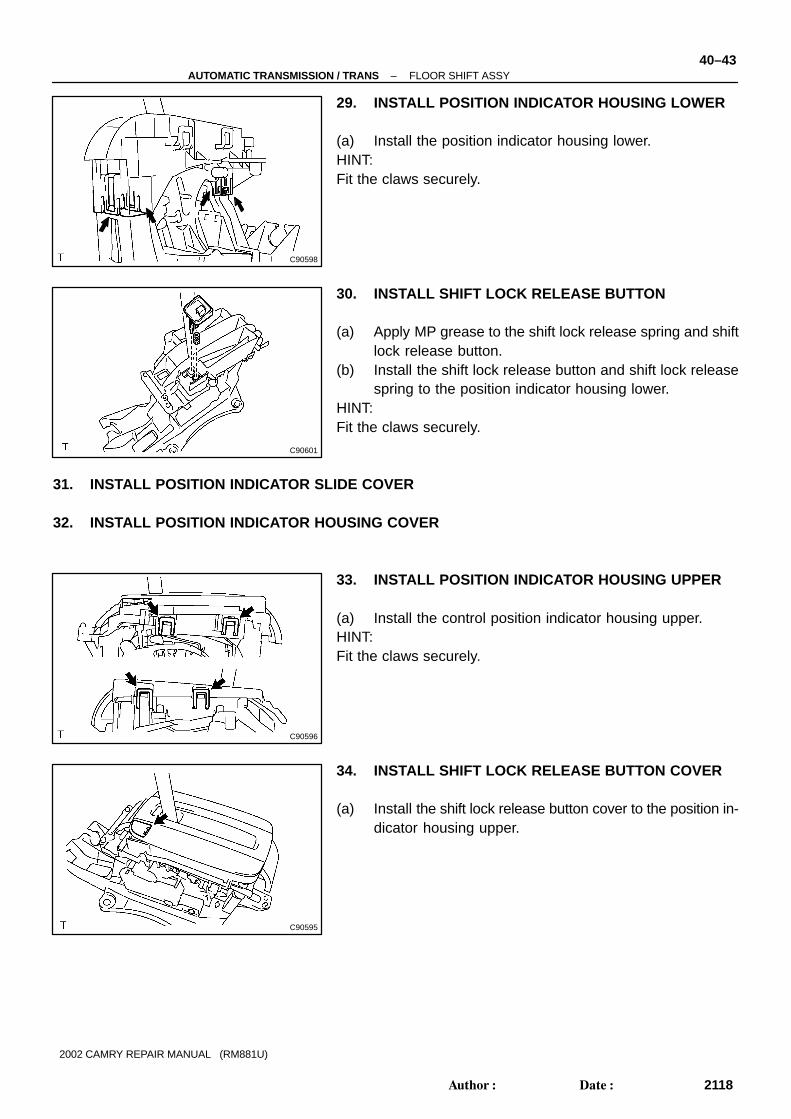
29. INSTALL POSITION INDICATOR HOUSING LOWER
(a) Install the position indicator housing lower.HINT:Fit the claws securely.
30. INSTALL SHIFT LOCK RELEASE BUTTON
(a) Apply MP grease to the shift lock release spring and shiftlock release button.
(b) Install the shift lock release button and shift lock releasespring to the position indicator housing lower.
HINT:Fit the claws securely.
31. INSTALL POSITION INDICATOR SLIDE COVER
32. INSTALL POSITION INDICATOR HOUSING COVER
33. INSTALL POSITION INDICATOR HOUSING UPPER
(a) Install the control position indicator housing upper.HINT:Fit the claws securely.
34. INSTALL SHIFT LOCK RELEASE BUTTON COVER
(a) Install the shift lock release button cover to the position in-dicator housing upper.

C90602
C92357
C90590
40–44–AUTOMATIC TRANSMISSION / TRANS FLOOR SHIFT ASSY
2119Author�: Date�:
2002 CAMRY REPAIR MANUAL (RM881U)
35. INSTALL SHIFT LEVER KNOB BUTTON
(a) Apply MP grease to the shift lever knob button and com-pression spring and install them to the shift lever knob.
HINT:Fit the claws securely.
36. INSTALL TRANSMISSION CONTROL SWITCH
(a) Install the transmission control switch to the shift lever knob.HINT:Fit the claws securely.37. INSTALL POSITION INDICATOR SLIDE COVER
(a) Install the position indicator slide cover to the shift lever.38. INSTALL FLOOR SHIFT SHIFT LEVER KNOB
SUB–ASSY
(a) Install the wire harness of the transmission control switch.
(b) Install the shift lever knob to the shift lever with 2 screws.(c) Install the position indicator slide cover to the shift lever
knob.
39. INSTALL INDICATOR LAMP WIRE SUB–ASSY
(a) Install the indicator lamp bulb and indicator lamp cap tothe indicator lamp wire.
(b) Connect the transmission control switch wire harness tothe indicator lamp wire harness connector.
(c) Install the indicator lamp wire to the position indicatorhousing lower.
(d) Install the indicator lamp wire harness and connector asshown in the illustration.

C90589A
B
C
D
C92346
C92314
C92571 C92745
TMC Made:
TMMK Made:
Accessory tool
Accessory tool
C90586
–AUTOMATIC TRANSMISSION / TRANS FLOOR SHIFT ASSY40–45
2120Author�: Date�:
2002 CAMRY REPAIR MANUAL (RM881U)
40. INSTALL FLOOR SHIFT ASSY(a) Install the floor shift assy to the vehicle with the 4 bolts.
Torque: 11.8 N ⋅m (122 kgf ⋅cm, 9 ft ⋅lbf)HINT:Tighten them in the order, A, B, C and D.(b) Connect the transmission control switch connector.(c) Connect the shift lock control computer connector.
41. CONNECT FLOOR SHIFT CABLE TRANSMISSIONCONTROL SHIFT
(a) Connect the floor shift cable to the floor shift assy.HINT:� Install it with the uneven surface facing to up.� Fit the claws securely.
42. CONNECT FLOOR SHIFT PARKING LOCK CABLEASSY
(a) Set the accessory tool.(1) Shift the shift lever to P position and turn the ignition
switch to LOCK. (TMC made)(2) Shift the shift lever to N position and turn the ignition
switch to ACC. (TMMK made)(3) Set the accessory tool to the shift lock control unit
assy as shown in the illustration.Accessory tool parts No.:TMC Made: 33693–33010TMMK Made: 33693–06010
HINT:Only in the case of reusing the shift lock control unit assy.
(b) Using a screwdriver, unlock the claw of the lock key of au-tomatic adjustment part.
C92665
C63997
40–46–AUTOMATIC TRANSMISSION / TRANS FLOOR SHIFT ASSY
2121Author�: Date�:
2002 CAMRY REPAIR MANUAL (RM881U)
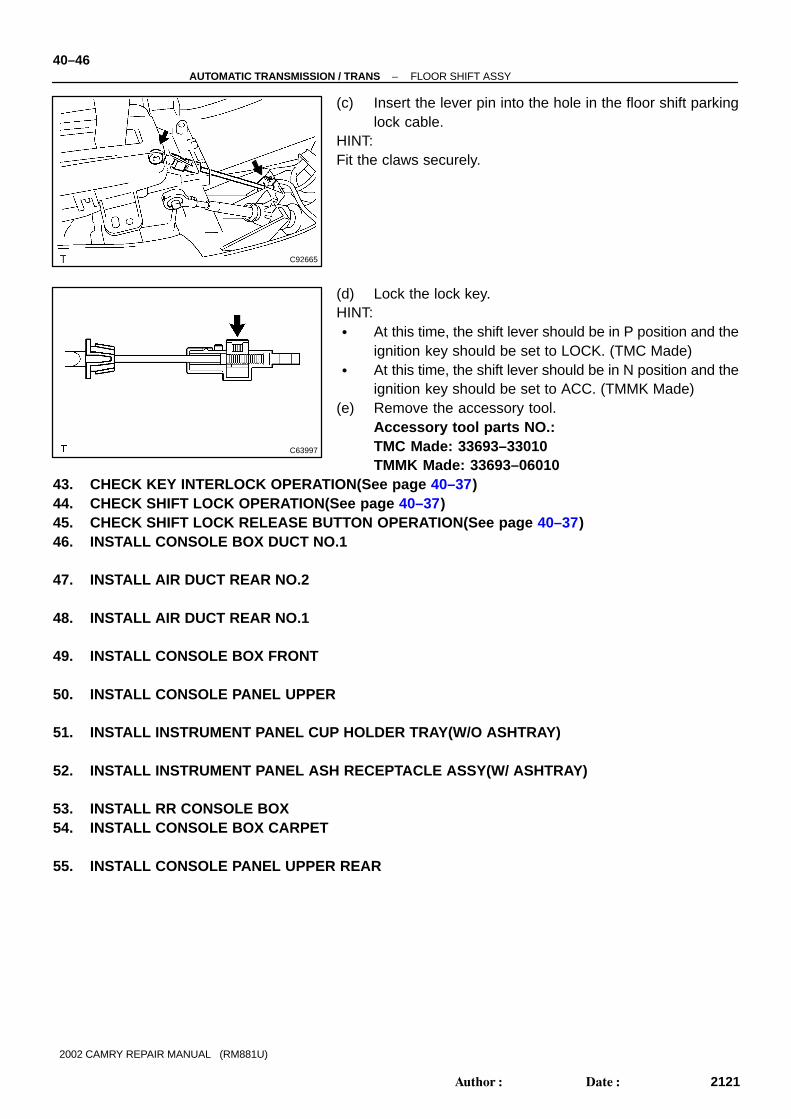
(c) Insert the lever pin into the hole in the floor shift parkinglock cable.
HINT:Fit the claws securely.
(d) Lock the lock key.HINT:� At this time, the shift lever should be in P position and the
ignition key should be set to LOCK. (TMC Made)� At this time, the shift lever should be in N position and the
ignition key should be set to ACC. (TMMK Made)(e) Remove the accessory tool.
Accessory tool parts NO.:TMC Made: 33693–33010TMMK Made: 33693–06010
43. CHECK KEY INTERLOCK OPERATION(See page 40–37)44. CHECK SHIFT LOCK OPERATION(See page 40–37)45. CHECK SHIFT LOCK RELEASE BUTTON OPERATION(See page 40–37)46. INSTALL CONSOLE BOX DUCT NO.1
47. INSTALL AIR DUCT REAR NO.2
48. INSTALL AIR DUCT REAR NO.1
49. INSTALL CONSOLE BOX FRONT
50. INSTALL CONSOLE PANEL UPPER
51. INSTALL INSTRUMENT PANEL CUP HOLDER TRAY(W/O ASHTRAY)
52. INSTALL INSTRUMENT PANEL ASH RECEPTACLE ASSY(W/ ASHTRAY)
53. INSTALL RR CONSOLE BOX54. INSTALL CONSOLE BOX CARPET
55. INSTALL CONSOLE PANEL UPPER REAR

40069–02
F00693
With the brake pedal depressed,shift while holding the shift leverknob button in. (The ignitionswitch must be in ON position.)
Shift normally
Shift while holding the shiftlever knob button in.
D25118
D25119
–AUTOMATIC TRANSMISSION / TRANS FLOOR SHIFT ASSY40–47
2122Author�: Date�:
2002 CAMRY REPAIR MANUAL (RM881U)
ADJUSTMENT
1. INSPECT SHIFT LEVER POSITION(a) When shifting the shift lever to each position, make sure
that it moves smoothly, and the position indicator displayscorrectly.Positions which can be shifted without pressing theshift lever knob buttonR → N → D, L → 2 → D → NPositions which can be operated only while pressingthe shift lever knob buttonD → 2 → L, N → R → PPositions which can be operated only while pressingthe shift lever knob button, ignition switch ON andbrake pedal depressedP → R
(b) Start the engine and make sure that the vehicle movesforward when shifting the lever from N to D position, andmoves rearward when shifting to R position.
2. ADJUST SHIFT LEVER POSITION(a) Loosen the nut on the control shaft lever.
(b) Push the control shaft fully downward.(c) Return the control shaft lever 2 notches to N position.(d) Set the shift lever to N position.(e) While holding the shift lever lightly toward the R position
side, tighten the shift lever nut.Torque: 14.7 N·m (150 kgf·cm, 10 ft·lbf)
(f) Start the engine and make sure that the vehicle movesforward when shifting the lever from N to D position andmoves rearward when shifting it to R position.

400FM–01
40–48–AUTOMATIC TRANSMISSION / TRANS FLOOR SHIFT PARKING LOCK CABLE ASSY
2123Author�: Date�:
2002 CAMRY REPAIR MANUAL (RM881U)
FLOOR SHIFT PARKING LOCK CABLE ASSYREPLACEMENT1. PRECAUTION2. DISCONNECT BATTERY NEGATIVE TERMINAL3. REMOVE STEERING WHEEL COVER LOWER NO.2
(See page 50–6)4. REMOVE STEERING WHEEL COVER LOWER NO.3(W/O STEERING PAD SWITCH 4 SPOKE
STEERING WHEEL)(See page 50–6)
5. REMOVE CONNECTOR COVER(W/ STEERING PAD SWITCH 4 SPOKE STEERING WHEEL)(See page 50–6)
6. REMOVE STEERING WHEEL COVER LOWER NO.3(3 SPOKE STEERING WHEEL ASSY)(See page 50–6)
7. PLACE FRONT WHEELS FACING STRAIGHT AHEAD8. REMOVE HORN BUTTON ASSY
(See page 50–9 or 50–22)9. REMOVE STEERING WHEEL ASSY
(See page 50–9 or 50–22)SST 09950–50013 (09951–05010, 09952–05010, 09953–05020, 09954–05021)
10. REMOVE INSTRUMENT CLUSTER FINISH PANEL(See page 71–12)
11. REMOVE STEERING COLUMN COVER(See page 50–9 or 50–22)
12. REMOVE FRONT DOOR SCUFF PLATE LH(See page 71–12)
13. REMOVE COWL SIDE TRIM SUB–ASSY LH(See page 71–12)
14. REMOVE INSTRUMENT PANEL COIN BOX SUB–ASSY(See page 71–12)
15. REMOVE INSTRUMENT PANEL SUB–ASSY UPPER(See page 71–12)
16. REMOVE INSTRUMENT PNL INSERT SUB–ASSY LWR LH(See page 71–12)
17. REMOVE CONSOLE PANEL UPPER REAR(See page 71–12)
18. REMOVE CONSOLE BOX CARPET(See page 71–12)
19. REMOVE RR CONSOLE BOX(See page 71–12)20. REMOVE INSTRUMENT PANEL CUP HOLDER TRAY(W/O ASHTRAY)
(See page 71–12)21. REMOVE INSTRUMENT PANEL ASH RECEPTACLE ASSY(W/ ASHTRAY)
(See page 71–12)22. REMOVE CONSOLE PANEL UPPER
(See page 71–12)23. REMOVE CONSOLE BOX FRONT
(See page 71–12)24. REMOVE AIR DUCT REAR NO.2
(See page 55–29)

C92665
C90583
C90584
C90585
–AUTOMATIC TRANSMISSION / TRANS FLOOR SHIFT PARKING LOCK CABLE ASSY40–49
2124Author�: Date�:
2002 CAMRY REPAIR MANUAL (RM881U)
25. REMOVE AIR DUCT REAR NO.1(See page 55–29)
26. REMOVE CONSOLE BOX DUCT NO.1(See page 55–29)
27. REMOVE FLOOR SHIFT PARKING LOCK CABLEASSY
(a) Disconnect the parking lock cable end from the lever pinof the floor shift assembly.
(b) Using a screwdriver, disconnect the parking lock cablefrom the floor shift assembly and clamp.
(c) Disconnect the cable clamp.(d) Turn the ignition switch to ACC or ON.
(e) Using a screwdriver, remove the cable from the upperbracket.

C90585
C90584
C90583
C92314
C92571 C92745
TMC Made:
TMMK Made:
Accessory tool
Accessory tool
40–50–AUTOMATIC TRANSMISSION / TRANS FLOOR SHIFT PARKING LOCK CABLE ASSY
2125Author�: Date�:
2002 CAMRY REPAIR MANUAL (RM881U)
28. INSTALL FLOOR SHIFT PARKING LOCK CABLEASSY
(a) Turn the ignition switch to ACC or ON.(b) Connect the cable to the upper bracket.
(c) Connect the cable clamp.
(d) Insert the slide cap into the through hole and install.
(e) Set the accessory tool.(1) Shift the shift lever to P position and turn the ignition
switch to LOCK. (TMC made)(2) Shift the shift lever to N position and turn the ignition
switch to ACC. (TMMK made)(3) Set the accessory tool to the shift lock control unit
assy.Accessory tool parts No.:TMC Made: 33693–33010TMMK Made: 33693–06010
C90586
C92665
C63997
–AUTOMATIC TRANSMISSION / TRANS FLOOR SHIFT PARKING LOCK CABLE ASSY40–51
2126Author�: Date�:
2002 CAMRY REPAIR MANUAL (RM881U)
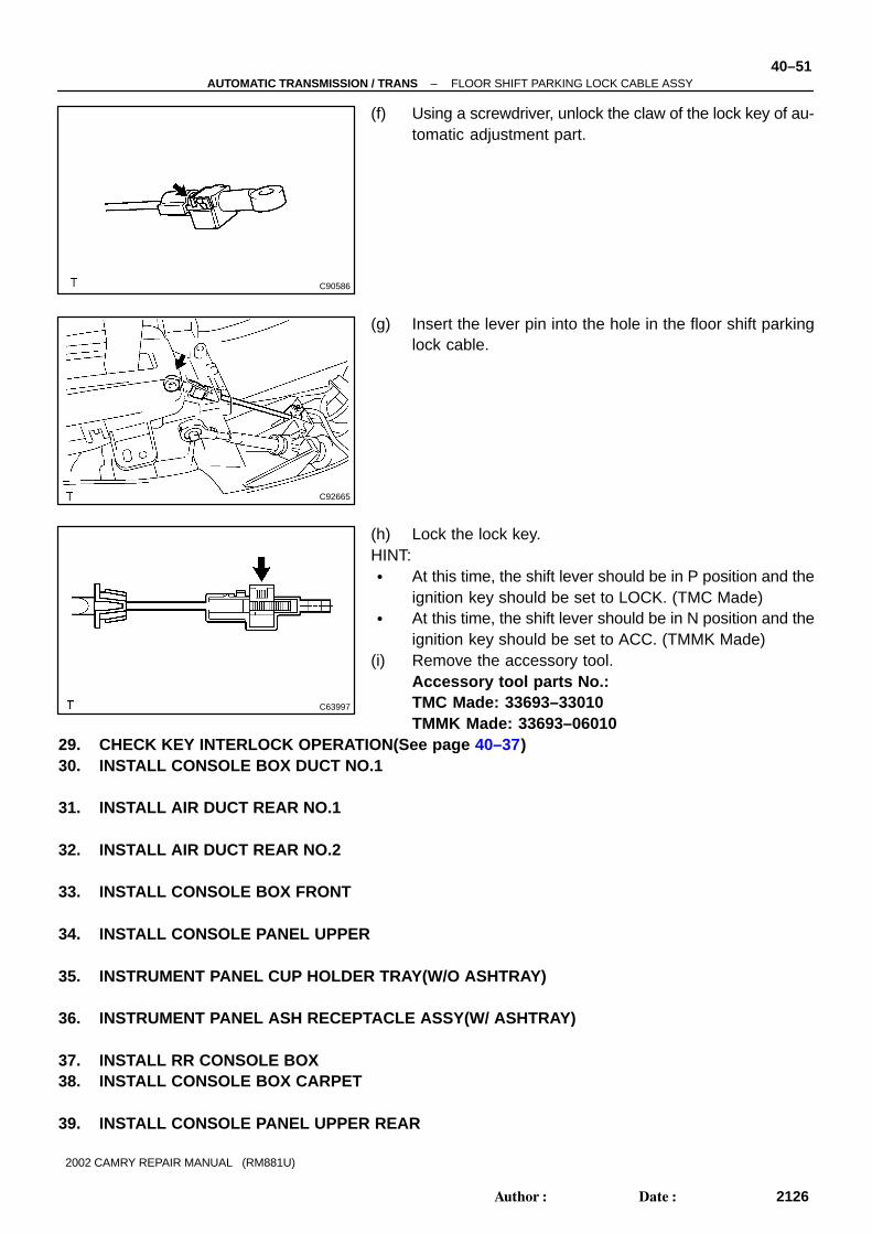
(f) Using a screwdriver, unlock the claw of the lock key of au-tomatic adjustment part.
(g) Insert the lever pin into the hole in the floor shift parkinglock cable.
(h) Lock the lock key.HINT:� At this time, the shift lever should be in P position and the
ignition key should be set to LOCK. (TMC Made)� At this time, the shift lever should be in N position and the
ignition key should be set to ACC. (TMMK Made)(i) Remove the accessory tool.
Accessory tool parts No.:TMC Made: 33693–33010TMMK Made: 33693–06010
29. CHECK KEY INTERLOCK OPERATION(See page 40–37)30. INSTALL CONSOLE BOX DUCT NO.1
31. INSTALL AIR DUCT REAR NO.1
32. INSTALL AIR DUCT REAR NO.2
33. INSTALL CONSOLE BOX FRONT
34. INSTALL CONSOLE PANEL UPPER
35. INSTRUMENT PANEL CUP HOLDER TRAY(W/O ASHTRAY)
36. INSTRUMENT PANEL ASH RECEPTACLE ASSY(W/ ASHTRAY)
37. INSTALL RR CONSOLE BOX38. INSTALL CONSOLE BOX CARPET
39. INSTALL CONSOLE PANEL UPPER REAR

40–52–AUTOMATIC TRANSMISSION / TRANS FLOOR SHIFT PARKING LOCK CABLE ASSY
2127Author�: Date�:
2002 CAMRY REPAIR MANUAL (RM881U)
40. INSTALL INSTRUMENT PNL INSERT SUB–ASSY LWR LH
41. INSTALL INSTRUMENT PANEL SUB–ASSY UPPER
42. INSTALL INSTRUMENT PANEL COIN BOX SUB–ASSY
43. INSTALL COWL SIDE TRIM SUB–ASSY LH
44. INSTALL FRONT DOOR SCUFF PLATE LH
45. INSTALL STEERING COLUMN COVER(See page 50–9 or 50–22)
46. INSTALL INSTRUMENT CLUSTER FINISH PANEL
47. INSTALL STEERING WHEEL ASSY(See page 50–9 or 50–22)
48. INSPECT STEERING WHEEL CENTER POINT49. INSTALL HORN BUTTON ASSY
(See page 50–9 or 50–22)50. INSTALL STEERING WHEEL COVER LOWER NO.2
(See page 50–6)51. INSTALL STEERING WHEEL COVER LOWER NO.3(W/O STEERING PAD SWITCH 4 SPOKE
STEERING WHEEL)(See page 50–6)
52. INSTALL CONNECTOR COVER(W/ STEERING PAD SWITCH 4 SPOKE STEERING WHEEL)(See page 50–6)
53. INSTALL STEERING WHEEL COVER LOWER NO.3(3 SPOKE STEERING WHEEL ASSY)(See page 50–6)
54. CONNECT BATTERY NEGATIVE TERMINAL55. INSPECT SRS WARNING LIGHT(See page 05–690)

400FN–01
C90581
D25414
D25415
–AUTOMATIC TRANSMISSION / TRANS FLOOR SHIFT CABLE TRANSMISSION CONTROLSHIFT
40–53
2128Author�: Date�:
2002 CAMRY REPAIR MANUAL (RM881U)
FLOOR SHIFT CABLE TRANSMISSION CONTROL SHIFTREPLACEMENT1. REMOVE INSTRUMENT PANEL SAFETY PAD SUB–ASSY
(See page 71–12)2. REMOVE AIR CONDITIONING RADIATOR ASSY
(See page 55–29)3. REMOVE AIR BAG SENSOR ASSY CENTER
(See page 60–56)4. REMOVE BATTERY5. REMOVE AIR CLEANER ASSY
6. REMOVE AIR CLEANER HOSE NO.1
7. REMOVE INTAKE AIR RESONATOR SUB–ASSY
8. DISCONNECT SHIFT CABLE GROMMET RETAINERNO.2
(a) Remove the 2 bolts and disconnect shift cable grommetretainer No.2.
9. REMOVE FLOOR SHIFT CABLE TRANSMISSIONCONTROL SHIFT
(a) Remove the nut from the control shaft lever.(b) Disconnect the control cable from the control shaft lever.
(c) Remove the clip and disconnect the control cable fromthe control cable bracket.

C90579
C90580
C90580
C90579
D25415
40–54 –AUTOMATIC TRANSMISSION / TRANS FLOOR SHIFT CABLE TRANSMISSION CONTROLSHIFT
2129Author�: Date�:
2002 CAMRY REPAIR MANUAL (RM881U)
(d) Disconnect the control cable from the control cableclamp.
(e) Disconnect the floor shift cable from the transmissionfloor shift assy.
(f) Pull out the control cable from the body.(g) Remove the shift cable grommet retainer No. 2.
10. INSTALL FLOOR SHIFT CABLE TRANSMISSIONCONTROL SHIFT
(a) Put in the control cable to the body.(b) Install the shift cable grommet retainer No.2 to the floor
shift cable.(c) Install the floor shift cable as shown in the illustration.HINT:� Install it with the uneven surface facing to up.� Fit the claws securely.
(d) Connect the control cable to the control cable clamp.
(e) Install the control cable and a new clip to the bracket.

D25414
C90581
–AUTOMATIC TRANSMISSION / TRANS FLOOR SHIFT CABLE TRANSMISSION CONTROLSHIFT
40–55
2130Author�: Date�:
2002 CAMRY REPAIR MANUAL (RM881U)
(f) Temporarily install the control cable to the control shaft le-ver with nuts.
11. INSTALL SHIFT CABLE GROMMET RETAINER NO.2
(a) Install the shift cable grommet retainer No.2 with the 2bolts.Torque: 4.9 N ⋅m (50 kgf ⋅cm, 43 in. ⋅lbf)
12. INSTALL AIR BAG SENSOR ASSY CENTER(See page 60–56)
13. INSTALL AIR CONDITIONING RADIATOR ASSY
14. ADJUST SHIFT LEVER POSITION(See page 40–47)15. INSPECT SHIFT LEVER POSITION(See page 40–47)16. INSTALL INTAKE AIR RESONATOR SUB–ASSY
17. INSTALL AIR CLEANER HOSE NO.1
18. INSTALL AIR CLEANER ASSY
19. INSTALL BATTERY