automatic power router
TRANSCRIPT

PTC Model III Programmable
Turntable Controller
Automatic Power Router
Installation Instructions
New York Railway SupplyNew York Railway SupplyNew York Railway SupplyNew York Railway Supply
13225 Thornton Dr Westlake, TX 76262 (817) 233-5068
http://www.nyrs.com
© NYRS Inc2010, Rev 7/10, US Patents Pending
A
APR Model I, Automatic Power Router Installation Instructions, Rev 7/10 - Page 2
APR Model I
Automatic Power Router Installation Instructions
OVERVIEW
The Automatic Power Routing Module (APR) provides a method for
removing power from turntable service tracks and optionally the
turntable lead track when the bridge is not pointing to them. The
APR can control up to 48 service tracks (47 if you are going to
switch power on the lead track). It will reduce the amount of wiring
necessary on the layout by not requiring switches on a control panel
to be connected to the service tracks. The APR can be installed at
anytime and does not have to be part of your initial installation of the
PTCIII.
The APR will work only with the PTCIII turntable controller with
versions stamped on them of at least 10.1 for rotary and pushbutton
or 11.1 for keypad track selectors. Contact NYRS for information on
upgrading your controller to these versions. The type of system used
to power the track does not matter for the APR. DC, AC, DCC are all
compatible.
TECHNICAL OVERVIEW
The PTCIII communicates with the APR via an RS-232 interface.
Upon power up the PTCIII transmits its current position to the
APR. After each position change the PTC transmits the new bridge
position to the APR. The APR disconnects the power to the existing
track at the end of the move and applies power to the newly selected
track.
The APR controller unit can switch up to 48 tracks. A remote relay
board is required for every 12 tracks. These boards are connected to
the APR unit via a ribbon cable. There are four connectors on the
back panel of the APR. An internal jumper block permits the option
of including up to 3 lead tracks in this count. If included the lead
tracks would be switched off when the bridge is not in position. This
would preclude engineers or runaway locos from driving off into the
pit. The other option is to not switch the lead tracks and this would
provide the means to switch additional service tracks.
Please review these instructions thoroughly before you begin to set
up your system.
APR - PARTS LIST
The Automatic Power Routing Kit includes the following parts:
• APR control unit
• Interconnect cable to PTCIII
• Relay board for each 12 tracks to be switched.
• These instructions.
ADDITIONAL ITEMS
• Power Supply for Relay Board – Either your own or optional
wall supply from NYRS. See Track Power section on Page 4.
• Mounting Hardware -To complete the installation, you will need
to some means to mount the relay boards to your benchwork.
We recommend some nylon spacers and wood screws obtainable
from any hardware store. See photos.
INSTALLATION
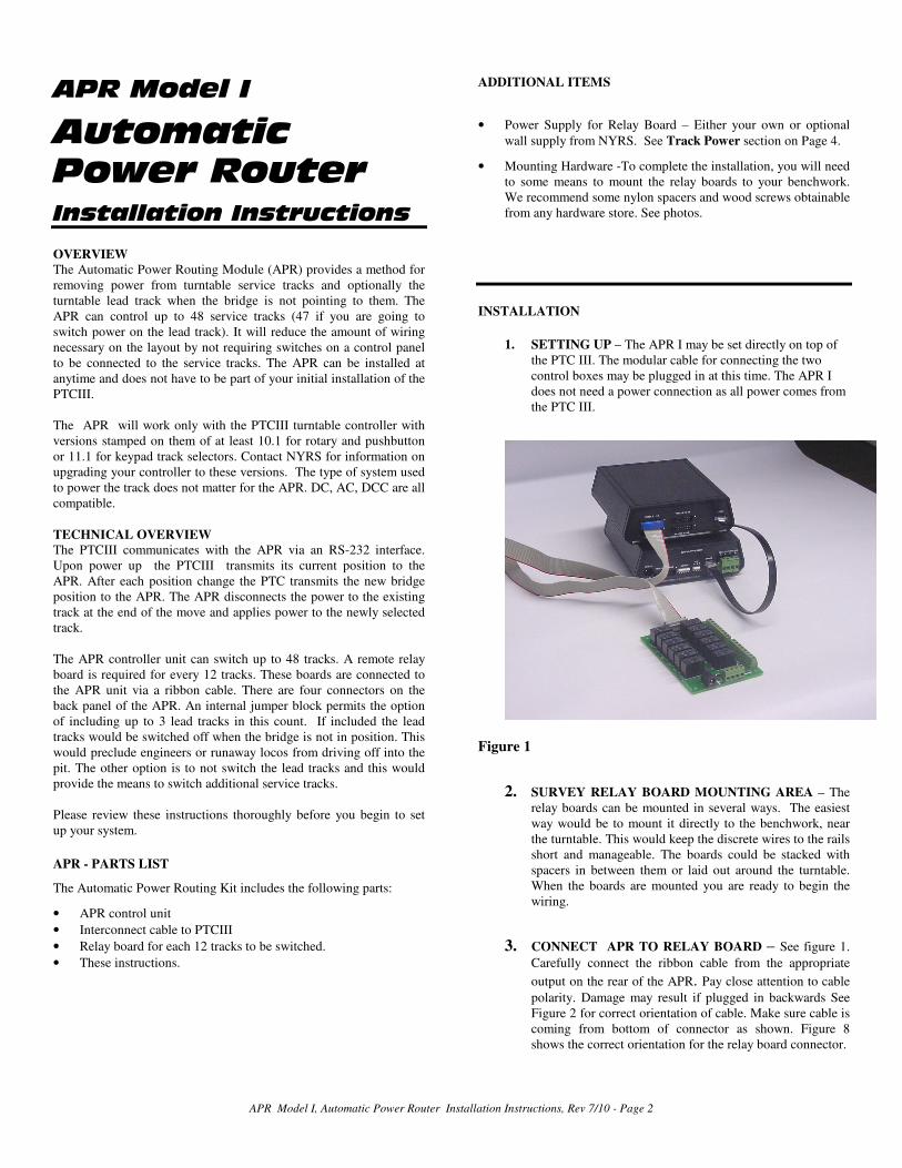
1. SETTING UP – The APR I may be set directly on top of
the PTC III. The modular cable for connecting the two
control boxes may be plugged in at this time. The APR I
does not need a power connection as all power comes from
the PTC III.
Figure 1
2. SURVEY RELAY BOARD MOUNTING AREA – The
relay boards can be mounted in several ways. The easiest
way would be to mount it directly to the benchwork, near
the turntable. This would keep the discrete wires to the rails
short and manageable. The boards could be stacked with
spacers in between them or laid out around the turntable.
When the boards are mounted you are ready to begin the
wiring.
3. CONNECT APR TO RELAY BOARD – See figure 1.
Carefully connect the ribbon cable from the appropriate
output on the rear of the APR. Pay close attention to cable
polarity. Damage may result if plugged in backwards See
Figure 2 for correct orientation of cable. Make sure cable is
coming from bottom of connector as shown. Figure 8
shows the correct orientation for the relay board connector.
APR Model I, Automatic Power Router Installation Instructions, Rev 7/10 - Page 3
Figure 2
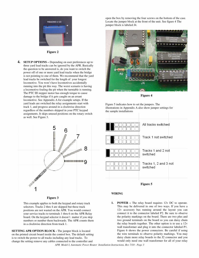
4. SETUP OPTIONS – Depending on user preferences up to
three yard lead tracks can be ignored by the APR. Basically
the question to be answered is, do you want to switch the
power off of one or more yard lead tracks when the bridge
is not pointing to one of them. We recommend that the yard
lead tracks be switched for the length of your longest
locomotive. You won’t have locomotives accidentally
running into the pit this way. The worst scenario is having
a locomotive fouling the pit when the turntable is running.
The PTC III stepper motor has enough torque to cause
damage to the bridge if it gets caught on an errant
locomotive. See Appendix A for example setups. If the
yard leads are switched the relay assignments start with
track 1, and progress around in a clockwise direction
regardless of the numbers skipped in your PTC keypad
assignments. It skips unused positions on the rotary switch
as well. See Figure 3.
Figure 3
This example applies to both the keypad and rotary track
selectors. Tracks 2 thru 4 are skipped but these track
positions are not wasted on the APR. You would connect
your service tracks to terminals 1 thru 6 on the APR Relay
board. On the keypad selector it doesn’t matter if you skip
numbers or number them backwards. The APR counts them
in a clockwise direction from track 1.
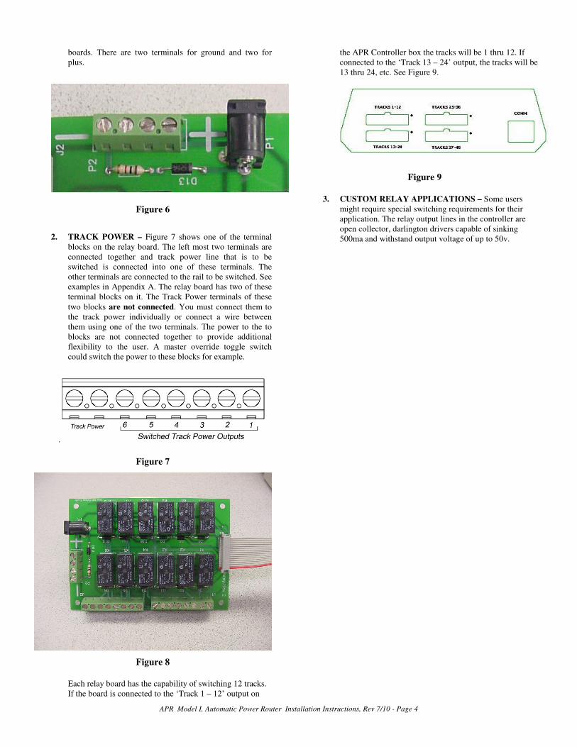
SETTING APR OPTION BLOCK - The jumper block is located
on the printed circuit board inside the control box. The default setting
is to switch the power to all tracks including any lead tracks. To
change the setting remove any cables connected to the controller and
open the box by removing the four screws on the bottom of the case.
Locate the jumper block at the front of the unit. See figure 4 The
jumper block is labeled J4.
Figure 4
Figure 5 indicates how to set the jumpers. The
illustrations in Appendix A also show jumper settings for
the sample installations
Figure 5
WIRING
1. POWER – The relay board requires 12v DC to operate.
This may be delivered in one of two ways. If you have a
12v accessory bus running around the layout you can
connect it to the connector labeled P2. Be sure to observe
the polarity markings on the board. There are two plus and
two ground terminals on the board so you can daisy chain
the relay boards together. The other option is to use a 12v
wall transformer and plug it into the connector labeled P1.
Figure 6 shows the power connectors. Be careful if using
the wire terminals to observe polarity markings. You may
daisy chain more relay boards to the J2 connector and you
would only need one wall transformer for all of your relay
APR Model I, Automatic Power Router Installation Instructions, Rev 7/10 - Page 4
boards. There are two terminals for ground and two for
plus.
Figure 6
2. TRACK POWER – Figure 7 shows one of the terminal
blocks on the relay board. The left most two terminals are
connected together and track power line that is to be
switched is connected into one of these terminals. The
other terminals are connected to the rail to be switched. See
examples in Appendix A. The relay board has two of these
terminal blocks on it. The Track Power terminals of these
two blocks are not connected. You must connect them to
the track power individually or connect a wire between
them using one of the two terminals. The power to the to
blocks are not connected together to provide additional
flexibility to the user. A master override toggle switch
could switch the power to these blocks for example.
.
Figure 7
Figure 8
Each relay board has the capability of switching 12 tracks.
If the board is connected to the ‘Track 1 – 12’ output on
the APR Controller box the tracks will be 1 thru 12. If
connected to the ‘Track 13 – 24’ output, the tracks will be
13 thru 24, etc. See Figure 9.
Figure 9
3. CUSTOM RELAY APPLICATIONS – Some users
might require special switching requirements for their
application. The relay output lines in the controller are
open collector, darlington drivers capable of sinking
500ma and withstand output voltage of up to 50v.

APR Model I, Automatic Power Router Installation Instructions, Rev 7/10 - Page 5
4.
APPENDIX A – Example Setups
Lead Tracks – 1
Service Tracks – 5
All tracks are switched using outputs 1 – 6 of APR.

APR Model I, Automatic Power Router Installation Instructions, Rev 7/10 - Page 6
Lead Tracks – 1
Service Tracks – 5
All service tracks are switched using outputs 1 – 5 of APR. Lead track is not switched.
APR Model I, Automatic Power Router Installation Instructions, Rev 7/10 - Page 7
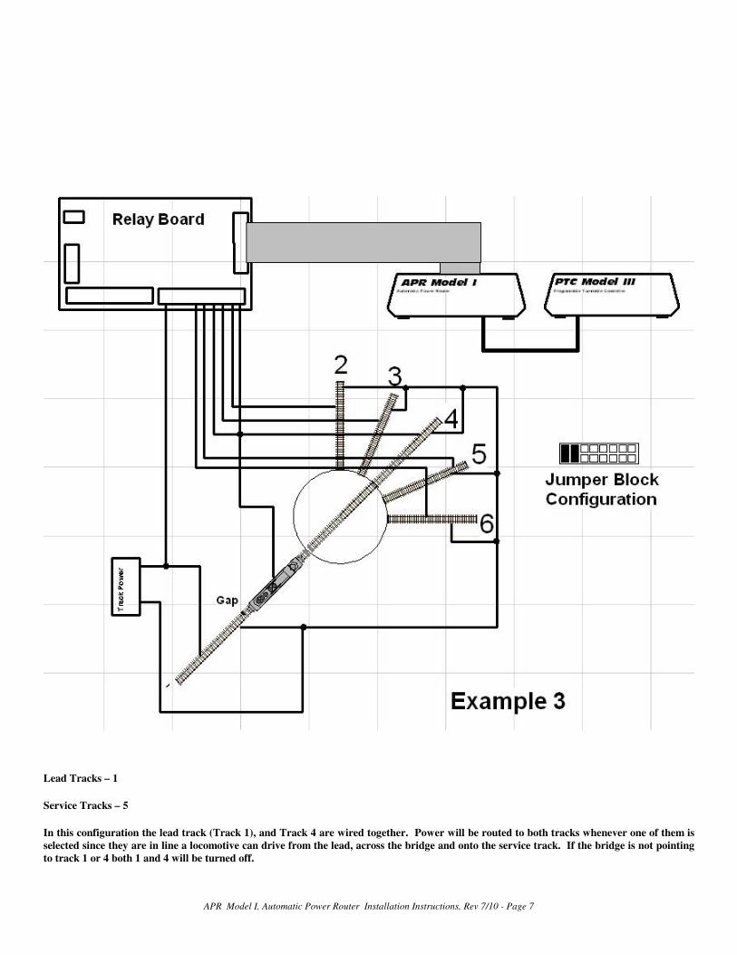
Lead Tracks – 1
Service Tracks – 5
In this configuration the lead track (Track 1), and Track 4 are wired together. Power will be routed to both tracks whenever one of them is
selected since they are in line a locomotive can drive from the lead, across the bridge and onto the service track. If the bridge is not pointing
to track 1 or 4 both 1 and 4 will be turned off.
APR Model I, Automatic Power Router Installation Instructions, Rev 7/10 - Page 8
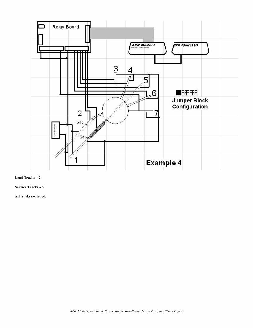
Lead Tracks – 2
Service Tracks – 5
All tracks switched.
APR Model I, Automatic Power Router Installation Instructions, Rev 7/10 - Page 9
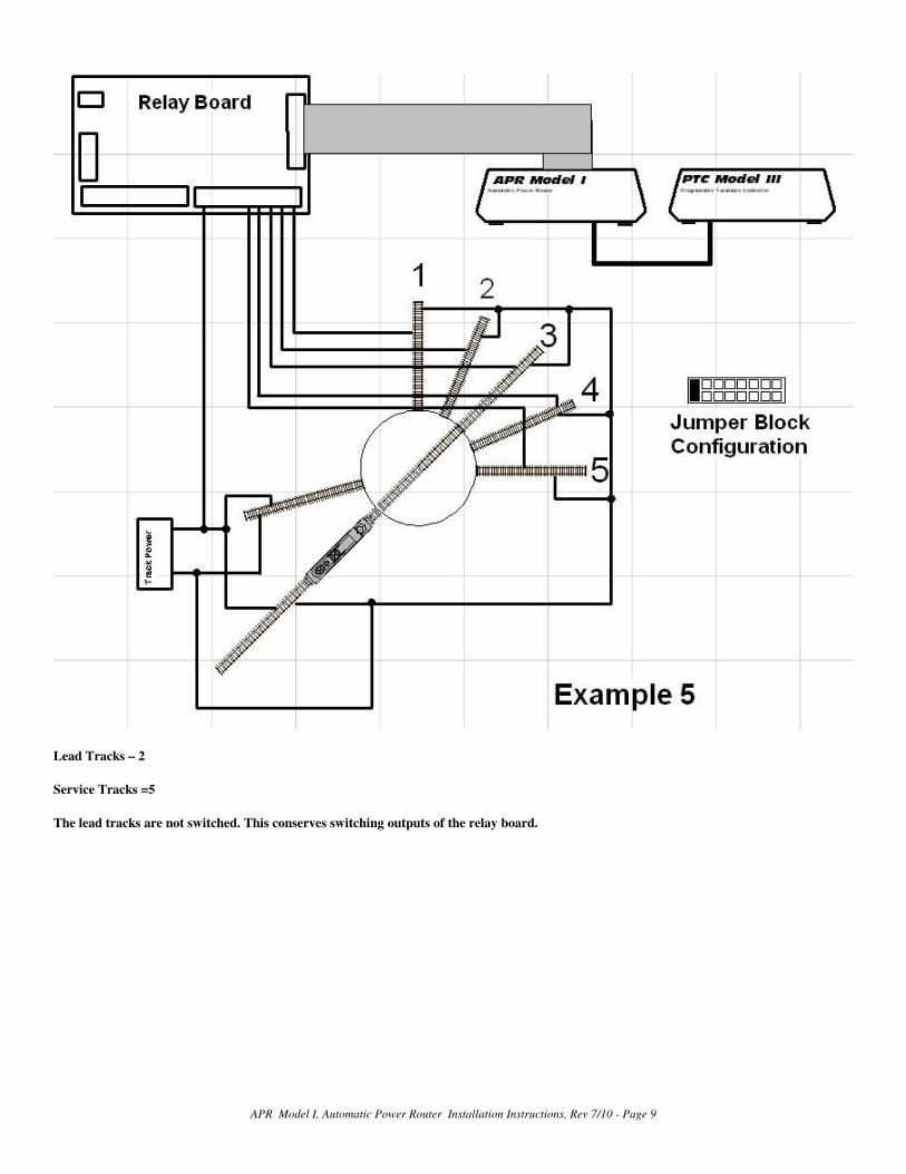
Lead Tracks – 2
Service Tracks =5
The lead tracks are not switched. This conserves switching outputs of the relay board.

APR Model I, Automatic Power Router Installation Instructions, Rev 7/10 - Page 10
Lead Tracks – 2
Service Tracks =5
The lead tracks are not switched. This conserves switching outputs of the relay board.

APR Model I, Automatic Power Router Installation Instructions, Rev 7/10 - Page 11
Lead Tracks – 3
Service Tracks =5
FOR MORE INFORMATION
This document and others are available in downloadable format at our web site, noted below. Feel welcome to call or write us at:
NEW YORK RAILWAY SUPPLY
13225 Thornton Dr Westlake, TX 76262
Tel: (817) 233-5068, Fax: (682) 831-0419
www.nyrs.com

APR Model I, Automatic Power Router Installation Instructions, Rev 7/10 - Page 12