automatic planning of laser measurements for a large-scale
TRANSCRIPT

Automatic Planning of Laser Measurements for a Large-scaleEnvironment using CPS-SLAM System
Souichiro Oshima1, Shingo Nagakura1, Jeong Yongjin1, Akihiro Kawamura2, Yumi Iwashita2, Ryo Kurazume2
Abstract— In recent years, several low-cost 3D laser scannersare being brought to the market and 3D laser scanningis becoming widely used in many fields. For example, 3Dmodeling of architectural structures or digital preservation ofcultural heritages are typical applications for 3D laser scanning.Despite of the development of light-weight and high-speed laserscanners, however, the complicated measurement procedureand long measurement time are still a heavy burden for thewidespread use of laser scanning. We have proposed a robotic3D scanning system using multiple robots named CPS-SLAM,which consists of parent robots with a 3D laser scanner andchild robots with target markers. In this system, a large-scale 3D model can be acquired by an on-board 3D laserscanner on a parent robot from several positions determinedprecisely by the localization technique using multiple robotsnamed Cooperative Positioning System, CPS. Therefore, thissystem enables to build a 3D model without complicated post-processing procedures such as ICP. In addition, this systemis an open-loop SLAM system and a quite precise 3D modelcan be obtained without closed loops. This paper proposesan automatic planning technique of a laser measurement forCPS-SLAM. By planning a proper scanning strategy dependingon a target structure, it is possible to perform laser scanningefficiently and accurately even for a large-scale and complexenvironment. Proposed technique plans an efficient scanningstrategy automatically by taking account of several criteria,such as visibility between robots, error accumulation, andefficient traveling. We conducted computer simulations andoutdoor experiments to verify the performance of the proposedtechnique.
Index Terms— Laser measurement, Multiple robots, 3D mod-elling, Automatic sensing planning
I. INTRODUCTION
Owing to the development of low-cost laser measurementsystems such as FARO Focus 3D, Leica Scanstation, andTOPCON GLS-1500, laser measurement is becoming popu-lar in recent years in civil engineering, construction, or digitalpreservation of historical cultural properties.
For acquiring a whole 3D model of a large-scale architec-ture, multiple laser scanning has to be performed repeatedlyaround the target architecture. Then the obtained partialrange data are aligned precisely using predefined markersor data points themselves by ICP (Iterative Closest Point) orNDT (Normal Distribution Transform) algorithms. In these
1 Souichiro Oshima, Shingo Nagakura, Jeong Yongjin are withFaculty of Information Science and Electrical Engineering, KyushuUniversity, 744, Motooka, Nishi-ku, Fukuoka, 8190395, [email protected]
2 Akihiro Kawamura, Yumi Iwashita and Ryo Kurazumeare with the Department of Information Science and ElectricalEngineering, Kyushu University, Kyushu University, 744, Motooka,Nishi-ku, Fukuoka, 8190395, JAPAN {kawamura, yumi,kurazume}@ait.kyushu-u.ac.jp
procedures, the Next Best View (NBV) problem, whichplans best scanning positions to capture a whole 3D modelefficiently, is quite important to reduce the measurement timeand scanning cost. However, in actual fields, a scanningstrategy is often determined by the operator’s experiencesand intuitions.
We have been developing a multiple robot system namedCPS-SLAM, which consists of a parent robot and multiplechild robots, for scanning a large-scale architecture. In thissystem, a parent robot is equipped with a laser measurementdevice such as a total station, and child robots are equippedwith target markers. For localizing the parent robot, thechild robots keep stand-still state and act as landmarks.Meanwhile, for localizing the child robots, the parent robotstops and acts as a landmark vice versa. By using thelaser measurement device and the target markers, the robotpositions are determined with the high accuracy of landsurveying. Since the parent and child robots move coordi-nately to localize each other, we call this the cooperativepositioning system or CPS [1]. Moreover, laser scanningis performed repeatedly by the laser scanner mounted onthe parent robot at a number of locations whose positionsare determined precisely by CPS. The obtained range dataare aligned using their position information directly withoutapplying ICP or NDT algorithms. We have performed anumber of measurement experiments including the DazaifuTenmangu shrine in Japan or tunnel shape measurementexperiments in construction sites [2], [3].
Although the NBV problem is quite important even inthe CPS-SLAM system, the scan planning is usually de-termined manually based on the operator’s experiences andintuitions. Therefore, the efficiency and optimality have notbeen considered qualitatively and explicitly, and thus, insome cases, measurement time tends to become longer sincesome regions are overlapped unexpectedly or unnecessarymovements are planned.
This paper proposes a solution of the NBV problemfor the laser measurement system using multiple robots,CPS-SLAM. We consider the visibility between robots, thesuppression of error accumulation, and the efficient robotmovements and develop an automatic planning technique ofa large-scale architecture for CPS-SLAM.
II. RELATED WORKS
Optimum design of sensor positions which are utilizedfor, for instance, a security camera system has been studiedfor many years in the fields of computational geometry orcomputer vision [5], [6], [7].
2015 IEEE/RSJ International Conference on Intelligent Robots and Systems (IROS)Congress Center HamburgSept 28 - Oct 2, 2015. Hamburg, Germany
978-1-4799-9993-4/15/$31.00 ©2015 IEEE 4437
In general, this problem can be categorized into twocategories whether the geometry of an environment and/or atarget object is known or not. In case that the geometricalinformation is available, the problem of optimum sensorpositions which minimizes blind regions in a surveillancearea or an efficient appearance inspection planning havebeen considered. Especially, an optimum layout problem ofsensors (observers) in an indoor environment is caller as“art gallery problem”, and has been studied in the fieldof computer science [8], [9]. Allen et al. [10] proposed ainteractive layout planning system to reduce blind regions.
Topcuoglu et al. [11] shows a technique for a widetopological map which realizes an optimum sensor layoutand the confidentiality of the sensors at a same time. Chen[12] and Scotto [13] proposed optimum observation planningtechniques of an object with a known shape which achieveshigh efficiency and accuracy using a 3D range sensor. Prietoet al. [14] discussed an optimum inspection planning foran object with CAD data using a range sensor with highaccuracy.
On the other hand, for an object with unknown geo-metrical information, observation planning techniques for ashape measurement [15], [16], [17], [18], [19] and activerecognition systems utilizing sensor motions [20], [21] havebeen proposed. Okamoto et al. [22] proposed a fundamentalscheme for the NBV problem which determines a properobservation location utilizing a stochastic observation modeland probabilistic sensor fusion technique. Li et al. [19]utilized information entropy to describe an uncertainty ofan observation model, and selected an optimum location atwhich the acquired information is expected to be maximizedas a solution of the NBV problem.
The technique proposed in this paper belongs to the lattercase. However, since CPS-SLAM utilizes the CooperativePositioning System (CPS) for localization of multiple robotsas described below, we have to consider some strong re-strictions such that the robots must be seen each other.Therefore, the proposed approach is quite different from theconventional problems mentioned above in which the viewposition can be chosen freely.
III. LASER MEASUREMENT SYSTEM USING MULTIPLE
ROBOTS FOR A LARGE-SCALE ARCHITECTURE,CPS-SLAM
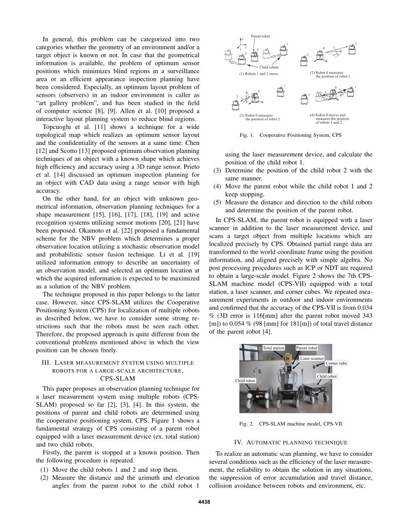
This paper proposes an observation planning technique fora laser measurement system using multiple robots (CPS-SLAM) proposed so far [2], [3], [4]. In this system, thepositions of parent and child robots are determined usingthe cooperative positioning system, CPS. Figure 1 shows afundamental strategy of CPS consisting of a parent robotequipped with a laser measurement device (ex. total station)and two child robots.
Firstly, the parent is stopped at a known position. Thenthe following procedure is repeated.
(1) Move the child robots 1 and 2 and stop them.(2) Measure the distance and the azimuth and elevation
angles from the parent robot to the child robot 1
02
1y
z
x
Parent robot
Child robots
(1) Robots 1 and 2 move. (2) Robot 0 measures the position of robot 1.
1
2
0 r1
1
1ψ
φ
(3) Robot 0 measures the position of robot 2.
1
2
0
2
2
r2
ψ
φ
(4) Robot 0 moves and measures the position of robots 1 and 2.
1
2
0
1
r1
1ψφr2
φ22ψ
Fig. 1. Cooperative Positioning System, CPS
using the laser measurement device, and calculate theposition of the child robot 1.
(3) Determine the position of the child robot 2 with thesame manner.
(4) Move the parent robot while the child robot 1 and 2keep stopping.
(5) Measure the distance and direction to the child robotsand determine the position of the parent robot.
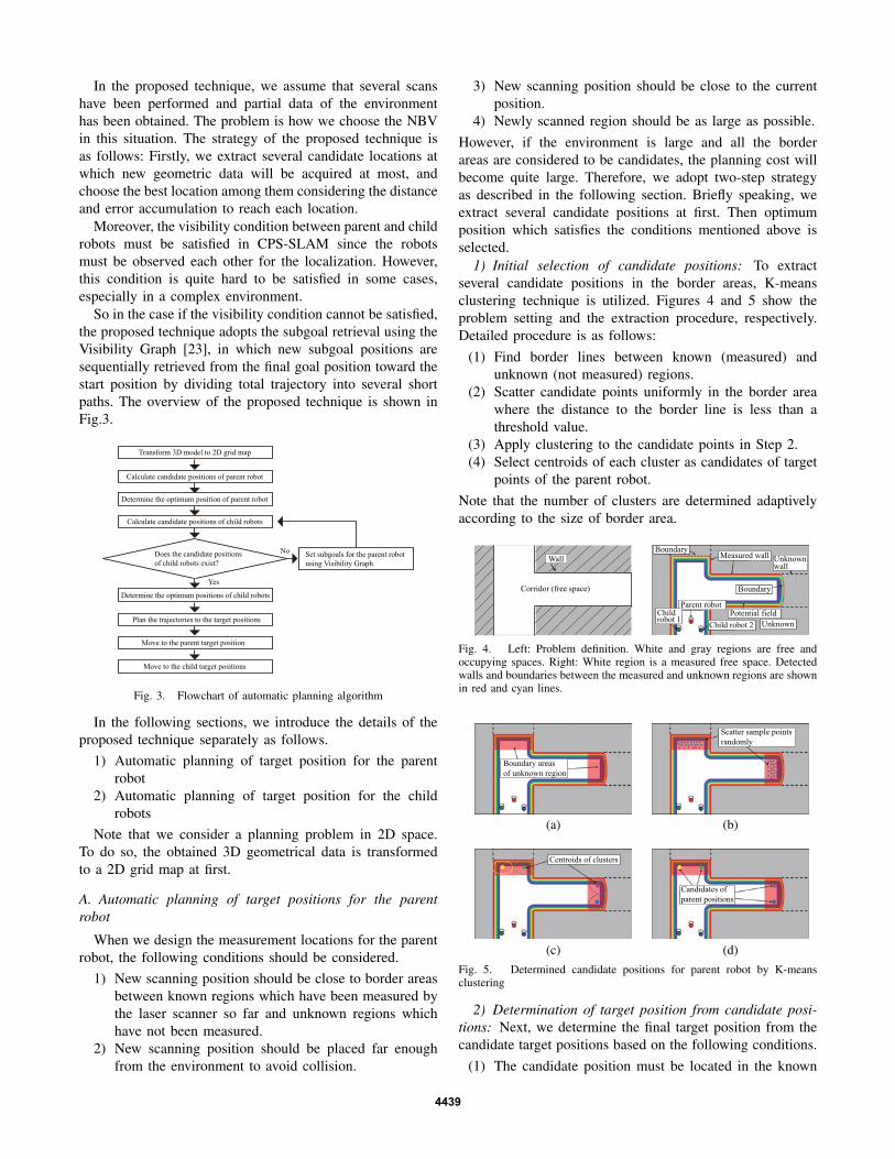
In CPS-SLAM, the parent robot is equipped with a laserscanner in addition to the laser measurement device, andscans a target object from multiple locations which arelocalized precisely by CPS. Obtained partial range data aretransformed to the world coordinate frame using the positioninformation, and aligned precisely with simple algebra. Nopost processing procedures such as ICP or NDT are requiredto obtain a large-scale model. Figure 2 shows the 7th CPS-SLAM machine model (CPS-VII) equipped with a totalstation, a laser scanner, and corner cubes. We repeated mea-surement experiments in outdoor and indoor environmentsand confirmed that the accuracy of the CPS-VII is from 0.034% (3D error is 116[mm] after the parent robot moved 343[m]) to 0.054 % (98 [mm] for 181[m]) of total travel distanceof the parent robot [4].
Total station Parent robot
Corner cube
Child robotChild robot
Laser scanner
Fig. 2. CPS-SLAM machine model, CPS-VII
IV. AUTOMATIC PLANNING TECHNIQUE
To realize an automatic scan planning, we have to considerseveral conditions such as the efficiency of the laser measure-ment, the reliability to obtain the solution in any situations,the suppression of error accumulation and travel distance,collision avoidance between robots and environment, etc.
4438
In the proposed technique, we assume that several scanshave been performed and partial data of the environmenthas been obtained. The problem is how we choose the NBVin this situation. The strategy of the proposed technique isas follows: Firstly, we extract several candidate locations atwhich new geometric data will be acquired at most, andchoose the best location among them considering the distanceand error accumulation to reach each location.
Moreover, the visibility condition between parent and childrobots must be satisfied in CPS-SLAM since the robotsmust be observed each other for the localization. However,this condition is quite hard to be satisfied in some cases,especially in a complex environment.
So in the case if the visibility condition cannot be satisfied,the proposed technique adopts the subgoal retrieval using theVisibility Graph [23], in which new subgoal positions aresequentially retrieved from the final goal position toward thestart position by dividing total trajectory into several shortpaths. The overview of the proposed technique is shown inFig.3.
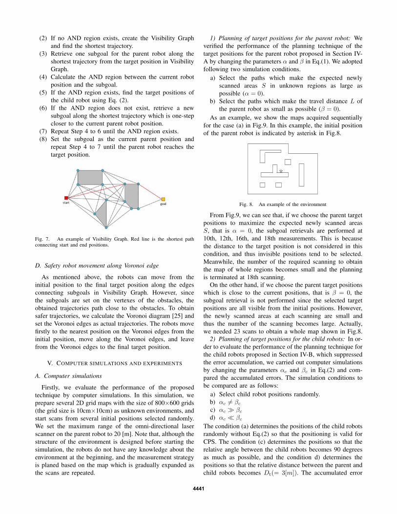
Transform 3D model to 2D grid map
Calculate candidate positions of parent robot
Determine the optimum position of parent robot
Calculate candidate positions of child robots
Does the candidate positions
of child robots exist?
Determine the optimum positions of child robots
Plan the trajectories to the target positions
Move to the parent target position
Move to the child target positions
Set subgoals for the parent robot
using Visibility Graph
No
Yes
Fig. 3. Flowchart of automatic planning algorithm
In the following sections, we introduce the details of theproposed technique separately as follows.
1) Automatic planning of target position for the parentrobot
2) Automatic planning of target position for the childrobots
Note that we consider a planning problem in 2D space.To do so, the obtained 3D geometrical data is transformedto a 2D grid map at first.
A. Automatic planning of target positions for the parentrobot
When we design the measurement locations for the parentrobot, the following conditions should be considered.
1) New scanning position should be close to border areasbetween known regions which have been measured bythe laser scanner so far and unknown regions whichhave not been measured.
2) New scanning position should be placed far enoughfrom the environment to avoid collision.
3) New scanning position should be close to the currentposition.
4) Newly scanned region should be as large as possible.
However, if the environment is large and all the borderareas are considered to be candidates, the planning cost willbecome quite large. Therefore, we adopt two-step strategyas described in the following section. Briefly speaking, weextract several candidate positions at first. Then optimumposition which satisfies the conditions mentioned above isselected.
1) Initial selection of candidate positions: To extractseveral candidate positions in the border areas, K-meansclustering technique is utilized. Figures 4 and 5 show theproblem setting and the extraction procedure, respectively.Detailed procedure is as follows:
(1) Find border lines between known (measured) andunknown (not measured) regions.
(2) Scatter candidate points uniformly in the border areawhere the distance to the border line is less than athreshold value.
(3) Apply clustering to the candidate points in Step 2.(4) Select centroids of each cluster as candidates of target
points of the parent robot.
Note that the number of clusters are determined adaptivelyaccording to the size of border area.
Parent robot
Corridor (free space)
Wall Measured wall Unknown wall
Parent robotChild robot 1
Child robot 2
Potential field
Unknown
Boundary
Boundary
Fig. 4. Left: Problem definition. White and gray regions are free andoccupying spaces. Right: White region is a measured free space. Detectedwalls and boundaries between the measured and unknown regions are shownin red and cyan lines.
Boundary areas
of unknown region
(a)
Scatter sample points
randomly
(b)
Centroids of clusters
(c)
Candidates of
parent positions
(d)
Fig. 5. Determined candidate positions for parent robot by K-meansclustering
2) Determination of target position from candidate posi-tions: Next, we determine the final target position from thecandidate target positions based on the following conditions.
(1) The candidate position must be located in the known
4439

area and can be reached from the current parentposition.
(2) The candidate position must be distant from obstacles.(3) Travel distance from the current parent position is
small.(4) Expected newly scanned area in unknown regions is
large.To choose an optimum target position which satisfies
all the condition mentioned above, the following value isevaluated for each candidate target point.
G = R · (P−1 + αL−1 + β · S) (1)
where G is an evaluated value of each candidate target point,R is a constant value of 0 (unknown or inaccessible) or 1(known and accessible) which shows the grid condition ofthe candidate target point, P is a potential value (inverseof distance from the closest obstacle), L is a travel dis-tance from the current parent position, S is a size of anexpected newly scanned area in unknown regions where nogeometrical information has been obtained so far, and αand β are weights of terms, respectively. To calculate S,we assume that no objects other than the ones which havebeen measured until now exist in the environment. Thenwe count the number of grids which can be seen from thecandidate target position directly without being blocked byobstacles and are located within the maximum range of thelaser scanner except the areas scanned previously. We choosethe position with the maximum evaluation value among thecandidate target positions as the final target position of theparent robot.
B. Automatic planning of target position for the child robot
The target positions of the child robots have to be seenfrom both the final target position and the initial position ofthe parent robot, since the positioning with CPS is impossibleif obstacles exist between the parent and the child robots andcannot be seen from each other. In this paper, we call a regionfrom where both the initial and target parent positions arevisible as “AND region”.
Target position of parent robot
Parent robot
Child robot 2
Child robot 1
(a)
Visible from current position of parent robot
(b)
Visible from targetposition of parent robot
(c)
AND 領域
Candidate positions of child robots
AND region
(d)
Fig. 6. AND region and candidate positions for child robots
The candidate target position of the child robot is de-termined in this AND region according to the followingconditions.
(1) The candidate position must be located in the ANDregion and can be reached from the current childposition.
(2) The candidate position must be distant from obstacle.(3) Distance from the parent robot is less than a threshold.(4) Relative angle between two child robots from the
parent robot is close to 90 degrees.where (3) is established due to the performance of the lasermeasurement device and (4) is set based on the fact thatthe error accumulation in CPS is suppressed at most if therelative angles of the child robots is close to 90 degrees [24].
To select the candidate positions of the child robots whichsatisfy the conditions mentioned above, the following valueis calculated at every grids in AND regions to find optimumtarget positions of two child robots at the same time.
Gc = P−1 + αc · |θ − θt|−1 + βc · |D −Dt|−1 (2)
where Gc is an evaluated value of each candidate target point,P is a potential value (inverse of distance from the closestobstacle), θ is the relative angle between the two child robots,D is the distance from the target position of the parent robot,θt (= 90 degrees) and Dt are constant values, and αc andβc are weights of terms, respectively. If the current positionof the child robot is located in the AND region, we do notdetermine the next position and keep the child robot stayingat the current position.
C. Subgoal retrieval using Visibility Graph
In some cases in the procedure for determining the targetposition of the child robot mentioned above, proper candidatepositions which satisfy the visibility condition cannot beobtained. For example, if the target position of the parentrobot is quite far from the current position of the child robotand the child robot must pass though several corners to reachthere, the AND region in which both the current and targetpositions of the parent robot can be seen directly does notexist. In these cases, we adopt the subgoal retrieval usingthe Visibility Graph [23], in which new subgoal positions ofthe parent robot are sequentially retrieved from the final goalposition to the start position by dividing the total trajectoryinto several short paths.
The Visibility Graph is a graph representation of all theaccessible paths connecting the vertices of the obstacles inthe environment. Figure 7 shows an example of the VisibilityGraph. By applying graph search algorithms, the shortesttrajectory between the current and the target positions can beobtained. In this graph representation, each line connectingvertices indicates that both vertices can be seen from eachother. Therefore, if all the robots travel along this line,each robot can be seen from each other and thus the CPSprocedure is executable. Owing to this fact, we definitelyobtain trajectories to move from the current parent positionto the target parent position using CPS.
The detailed procedure for subgoal retrieval using theVisibility Graph is shown as follows:
(1) Confirm whether the AND region exists between thecurrent and target positions of the parent robot or not.
4440
(2) If no AND region exists, create the Visibility Graphand find the shortest trajectory.
(3) Retrieve one subgoal for the parent robot along theshortest trajectory from the target position in VisibilityGraph.
(4) Calculate the AND region between the current robotposition and the subgoal.
(5) If the AND region exists, find the target positions ofthe child robot using Eq. (2).
(6) If the AND region does not exist, retrieve a newsubgoal along the shortest trajectory which is one-stepcloser to the current parent robot position.
(7) Repeat Step 4 to 6 until the AND region exists.(8) Set the subgoal as the current parent position and
repeat Step 4 to 7 until the parent robot reaches thetarget position.
Fig. 7. An example of Visibility Graph. Red line is the shortest pathconnecting start and end positions.
D. Safety robot movement along Voronoi edge
As mentioned above, the robots can move from theinitial position to the final target position along the edgesconnecting subgoals in Visibility Graph. However, sincethe subgoals are set on the vertexes of the obstacles, theobtained trajectories path close to the obstacles. To obtainsafer trajectories, we calculate the Voronoi diagram [25] andset the Voronoi edges as actual trajectories. The robots movefirstly to the nearest position on the Voronoi edges from theinitial position, move along the Voronoi edges, and leavefrom the Voronoi edges to the final target position.
V. COMPUTER SIMULATIONS AND EXPERIMENTS
A. Computer simulations
Firstly, we evaluate the performance of the proposedtechnique by computer simulations. In this simulation, weprepare several 2D grid maps with the size of 800×600 grids(the grid size is 10cm×10cm) as unknown environments, andstart scans from several initial positions selected randomly.We set the maximum range of the omni-directional laserscanner on the parent robot to 20 [m]. Note that, although thestructure of the environment is designed before starting thesimulation, the robots do not have any knowledge about theenvironment at the beginning, and the measurement strategyis planed based on the map which is gradually expanded asthe scans are repeated.
1) Planning of target positions for the parent robot: Weverified the performance of the planning technique of thetarget positions for the parent robot proposed in Section IV-A by changing the parameters α and β in Eq.(1). We adoptedfollowing two simulation conditions.
a) Select the paths which make the expected newlyscanned areas S in unknown regions as large aspossible (α = 0).
b) Select the paths which make the travel distance L ofthe parent robot as small as possible (β = 0).
As an example, we show the maps acquired sequentiallyfor the case (a) in Fig.9. In this example, the initial positionof the parent robot is indicated by asterisk in Fig.8.
Fig. 8. An example of the environment
From Fig.9, we can see that, if we choose the parent targetpositions to maximize the expected newly scanned areasS, that is α = 0, the subgoal retrievals are performed at10th, 12th, 16th, and 18th measurements. This is becausethe distance to the target position is not considered in thiscondition, and thus invisible positions tend to be selected.Meanwhile, the number of the required scanning to obtainthe map of whole regions becomes small and the planningis terminated at 18th scanning.
On the other hand, if we choose the parent target positionswhich is close to the current positions, that is β = 0, thesubgoal retrieval is not performed since the selected targetpositions are all visible from the initial positions. However,the newly scanned areas at each scanning are small andthus the number of the scanning becomes large. Actually,we needed 23 scans to obtain a whole map shown in Fig.8.
2) Planning of target positions for the child robots: In or-der to evaluate the performance of the planning technique forthe child robots proposed in Section IV-B, which suppressedthe error accumulation, we carried out computer simulationsby changing the parameters αc and βc in Eq.(2) and com-pared the accumulated errors. The simulation conditions tobe compared are as follows:
a) Select child robot positions randomly.b) αc �= βc
c) αc � βc
d) αc � βc
The condition (a) determines the positions of the child robotsrandomly without Eq.(2) so that the positioning is valid forCPS. The condition (c) determines the positions so that therelative angle between the child robots becomes 90 degreesas much as possible, and the condition d) determines thepositions so that the relative distance between the parent andchild robots becomes Dt(= 3[m]). The accumulated error
4441
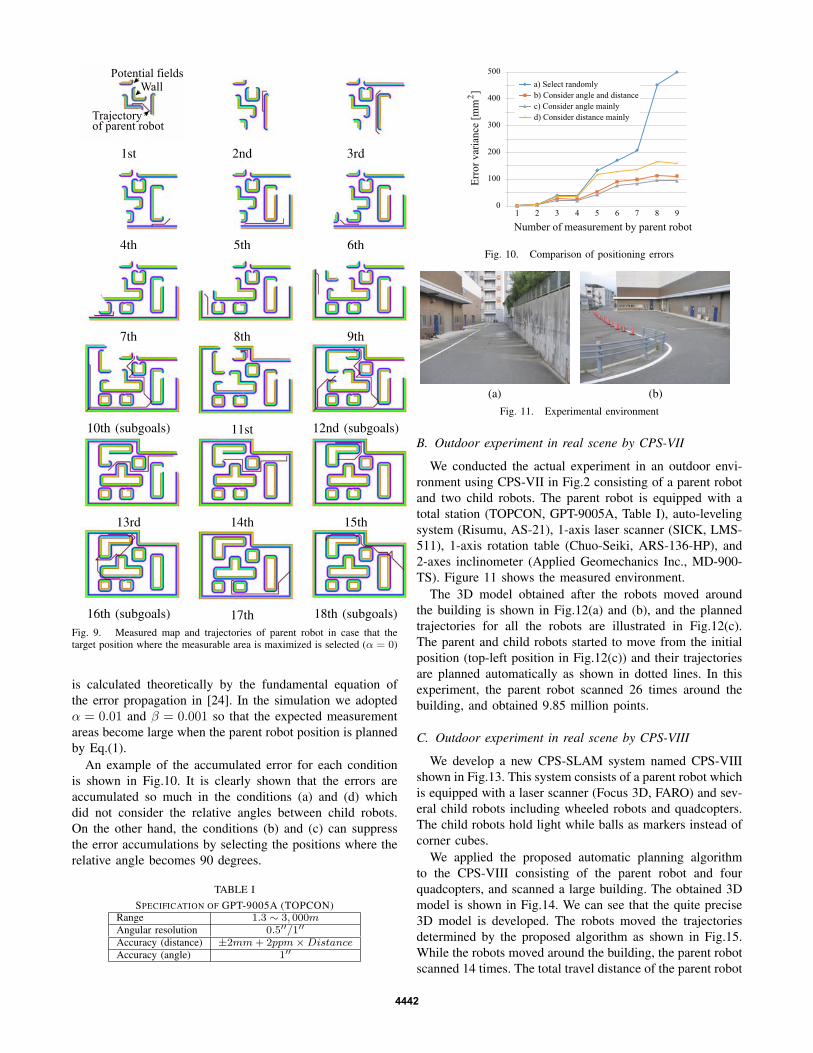
Potential fields
Trajectoryof parent robot
Wall
1st 2nd 3rd
4th 5th 6th
7th 8th 9th
10th (subgoals) 11st 12nd (subgoals)
13rd 14th 15th
16th (subgoals) 17th 18th (subgoals)Fig. 9. Measured map and trajectories of parent robot in case that thetarget position where the measurable area is maximized is selected (α = 0)
is calculated theoretically by the fundamental equation ofthe error propagation in [24]. In the simulation we adoptedα = 0.01 and β = 0.001 so that the expected measurementareas become large when the parent robot position is plannedby Eq.(1).
An example of the accumulated error for each conditionis shown in Fig.10. It is clearly shown that the errors areaccumulated so much in the conditions (a) and (d) whichdid not consider the relative angles between child robots.On the other hand, the conditions (b) and (c) can suppressthe error accumulations by selecting the positions where therelative angle becomes 90 degrees.
TABLE I
SPECIFICATION OF GPT-9005A (TOPCON)Range 1.3 ∼ 3, 000mAngular resolution 0.5′′/1′′Accuracy (distance) ±2mm+ 2ppm×DistanceAccuracy (angle) 1′′
0
100
200
300
400
500
1 2 3 4 5 6 7 8 9
Number of measurement by parent robot
Err
or
var
iance
[m
m ]
2
a) Select randomly
b) Consider angle and distance
c) Consider angle mainly
d) Consider distance mainly
Fig. 10. Comparison of positioning errors
(a) (b)
Fig. 11. Experimental environment
B. Outdoor experiment in real scene by CPS-VII
We conducted the actual experiment in an outdoor envi-ronment using CPS-VII in Fig.2 consisting of a parent robotand two child robots. The parent robot is equipped with atotal station (TOPCON, GPT-9005A, Table I), auto-levelingsystem (Risumu, AS-21), 1-axis laser scanner (SICK, LMS-511), 1-axis rotation table (Chuo-Seiki, ARS-136-HP), and2-axes inclinometer (Applied Geomechanics Inc., MD-900-TS). Figure 11 shows the measured environment.
The 3D model obtained after the robots moved aroundthe building is shown in Fig.12(a) and (b), and the plannedtrajectories for all the robots are illustrated in Fig.12(c).The parent and child robots started to move from the initialposition (top-left position in Fig.12(c)) and their trajectoriesare planned automatically as shown in dotted lines. In thisexperiment, the parent robot scanned 26 times around thebuilding, and obtained 9.85 million points.
C. Outdoor experiment in real scene by CPS-VIII
We develop a new CPS-SLAM system named CPS-VIIIshown in Fig.13. This system consists of a parent robot whichis equipped with a laser scanner (Focus 3D, FARO) and sev-eral child robots including wheeled robots and quadcopters.The child robots hold light while balls as markers instead ofcorner cubes.
We applied the proposed automatic planning algorithmto the CPS-VIII consisting of the parent robot and fourquadcopters, and scanned a large building. The obtained 3Dmodel is shown in Fig.14. We can see that the quite precise3D model is developed. The robots moved the trajectoriesdetermined by the proposed algorithm as shown in Fig.15.While the robots moved around the building, the parent robotscanned 14 times. The total travel distance of the parent robot
4442

(a) 3D model
(b) 3D model (Top view)
Parent robot
Child robot 2
Child robot 1
20m Slope (Height 1m)
(c) Trajectories
Fig. 12. 3D models and trajectories of parent and child robots (case 3)
is 270.1 [m]. The total number of points is 6.13 billions. Weadopted α = 0.01 and β = 0.001 for this experiment.
In addition, we evaluated the accuracy of the positioningand the 3D model by comparing positions of six corners ofthe 3D model which are in the circle shown in Fig.15 at 1stand 14th scanning. The average error of these six cornersis 23.1[mm], which is 0.0085% of total travel distance(270.1[m]). This result shows clearly that the proposed CPS-SLAM performs a quite accurate 3D modeling comparingconventional SLAM systems. One of the reasons why theaccuracy is improved comparing with CPS-VII is that thetotal station and the laser scanner in CPS-VII are integratedand replaced by the single laser scanner, and thus no calibra-tion error between these sensors exist in CPS-VIII. Figure16 shows the 3D model with some photos taken from thesame positions.
Note that we can apply ICP to the measured point data aswe did in [2]. However, we think that the absolute accuracycannot be guaranteed for aligned data since each data isaligned so that the total relative error is minimized. In theworst case, the obtained 3D model differs from the real shapeif the point correspondences are not determined appropri-ately. On the other hand, the proposed measurement systemcan guarantee the accuracy level in terms of the absoluteaccuracy, and thus it is quite useful for real applications
Parent robot
Quadcopter robots (child robots)
Child robotChild robot
3Dscanner
Target marker
(a) CPS-VIII
(b) Target balls on quadcopters
Fig. 13. The 8th CPS machine model, CPS-VIII
(a) View from point A in Fig.15
(b) Total view
Fig. 14. 3D model created by CPS-VIII
such as field robot navigation or 3D shape measurementsin construction sites.
VI. CONCLUSIONS
This paper proposes an automatic planning technique foran efficient laser measurement for the CPS-SLAM system,which realizes an accurate 3D modeling using multiplerobots and a laser scanner. By planning a proper scanningstrategy which satisfies several conditions to validate CPSmotion, efficient and accurate laser scanning can be per-formed even for a large-scale environment. The proposedtechnique plans a reliable scanning trajectory using thesubgoal retrieval by Visibility Graph, and the minimizationof the error accumulation by considering the relative robotpositions is also realized. The validity of the proposedtechnique is verified through computer simulations and actual
4443

2345
6
7
8 9 10 11
12
13
Parent robot
Child robot
70m
114
A
D
C
B
E
Fig. 15. Route planned by the proposed algorithm
Photos 3D model
Fig. 16. Comparison with photos and 3D models captured from points B,C, D, and E in Fig.15
experiments in the outdoor environment. Although this paperdealt with the planning in 2D space, the proposed algorithmcan be applied to the planning in 3D space by consideringmutual visibilities and expected newly scanned areas in 3D.
ACKNOWLEDGEMENT
The present study was supported in part by a Grant-in-Aidfor Scientific Research (A) (26249029).
REFERENCES
[1] Ryo Kurazume, Shigemi Nagata, Shigeo Hirose: “Cooperative Posi-tioning with Multiple Robots”, Proc. IEEE Int. Conf. on Robotics andAutomation, Vol. 2, pp. 1250-1257, 1994.
[2] Ryo Kurazume, Yusuke Noda, Yukihiro Tobata, Kai Lingemann, YumiIwashita, Tsutomu Hasegawa: “Laser-based Geometric Modeling us-ing Cooperative Multiple Mobile Robots”, in Proc. IEEE Int. Conf.on Robotics and Automation, pp.3200-3205, May 12-17, 2009.
[3] Yukihiro Tobata, Ryo Kurazume, Yusuke Noda, Kai Lingemann, YumiIwashita, Tsutomu Hasegawa: Laser-based geometrical modeling oflarge-scale architectural structures using co-operative multiple robots’,Autonomous Robot, Vol.32, No.1, pp. 49-62, 2012.
[4] Yongjin Jeong, Ryo Kurazume, Yoonseok Pyo, Yumi Iwashita,Tsutomu Hasegawa, High-Precision Three-Dimensional Laser Mea-surement System by Cooperative Multiple Mobile Robots, 2012IEEE/SICE International Symposium on System Integration (SII2012),pp.198-205, 2012
[5] K. A. Tarabanis, P. K. Allen, and R. Y. Tsai, A survey of sensorplanning in computer vision, IEEE Trans. on Robotics and automation,Vol.RA-11, No.1, pp. 86-104, 1995.
[6] T.S. Newman and A.K. Jain, A survey of automated visual inspection,Computer Vision and Image Understanding, Vol.61, No.2, pp.231-262,1995.
[7] Aaron Mavrinac and Xiang Chen. Modeling coverage in cameranetworks: A survey, International journal of computer vision, Vol.101,No.1, 205-226, 2013.
[8] A. Aggarwal, The art gallery theorem: Its variations, applications, andalgorithmic aspects, Ph.D. thesis, Johns Hopkins University, 1984.
[9] J. O Rourke, Art Gallery Theorems and Algorithms. London, U.K.:Oxford Univ. Press, 1987.
[10] I. Stamos, P. K. Allen, Interactive sensor planning, Proc. of theIEEE Computer Society Conference on Computer Vision and PatternRecognition, pp.489-494, 1998.
[11] Haluk Rahmi Topcuoglu, Murat Ermis, and Mesut Sifyan, Positioningand Utilizing Sensors on a 3-D Terrain Part I Theory and Modeling,IEEE Trans. on Systems, Man and Cybernetics Part C: Applicationsand Reviews Vol.41, No.3, 2011.
[12] S.Y. Chen and Y.F. Li, Automatic sensor placement for model-basedrobot vision, Systems, Man, and Cybernetics, Part B: Cybernetics,IEEE Transactions on , vol.34, no.1, pp.393-408, 2004.
[13] W.R. Scott, G. Roth, and J.-F. Rivest, View planning with a regis-tration constraint, Proc. Third Int. Conf. on 3-D Digital Imaging andModeling, pp. 127 -134, 2001.
[14] F. Prieto, T. Redarce, et al, CAD-based range sensor placement foroptimum 3D data acquisition, Proc. Second Int. Conf. on 3-D DigitalImaging and Modeling, pp. 128 -137, 1999.
[15] D. Papadopoulos-Orfanos and F. Schmitt, Automatic 3-D digitizationusing a laser rangefinder with a small field of view, Conf. on RecentAdvances in 3-D Digital Imaging and Modeling, pp. 60 -67, 1997.
[16] H. Zha, K. Morooka, T. Hasegawa, and T. Nagata, Active modeling of3-D objects: Planning on the next best pose (NBP) for acquiring rangeimages, Proc. Int. Conf. on Recent Advances 3-D Digital ImagingModeling, pp. 68-75, 1997.
[17] E. Marchand and F. Chaumette, Active sensor placement for com-plete scene reconstruction and exploration, Proc. IEEE Int. Conf. onRobotics and Automation, pp. 743-750, 1997.
[18] S.Y. Chen and Y.F. Li, Vision sensor planning for 3-D model acqui-sition, IEEE Transactions on Systems, Man, and Cybernetics, Part B:Cybernetics, vol.35, no.5, pp.894-904 2005.
[19] Y.F. Li and Z.G. Liu, Information entropy-based viewpoint planningfor 3-D object reconstruction, IEEE Transactions on Robotics, vol.21,no.3, pp.324-337, 2005.
[20] Ruzena Bajcsy, Active perception,.Proc. of the IEEE, Vol.76, No.8,pp.966-1005, 1988.
[21] Yiannis Aloimonos, ed. Active perception. Psychology Press, 2013.[22] J. Okamoto, M. Milanova, U. Bueker, Active perception system for
recognition of 3D objects in image sequences, 5th Int. Workshop onAdvanced Motion Control, pp. 700-705, 1998.
[23] Mark de Berg et al., Computational Geometry: Algorithms and Ap-plications, Springer, 1997.
[24] Ryo Kurazume and Shigeo Hirose, “Study on Cooperative PositioningSystem - Optimum Moving Strategies for CPS-III -”, Proc. IEEE Int.Conf. on Robotics and Automation, Vol. 4, pp. 2896-2903, 1998.
[25] Franz Aurenhammer, Voronoi Diagrams, A Survey of a FundamentalGeometric Data Structure, ACM Computing Surveys (CSUR), Vol 23,Issue 3, pp.345-405, 1991.
4444