automatic identification systems (ais - nmea 2010 conference ais... · automatic identification...
TRANSCRIPT

Automatic Identification Systems
(AIS)
Automatic Identification Systems
–AIS Fundamentals–Equipment Installation–Configuration Requirements
What is an AIS?
An automated shipboard system operating on marine
VHF channels for the purpose of transmitting and
receiving vessel position, speed, heading and other
vessel specific information.

• Purpose: Increase Vessel Safety
– Automatic Exchange of Navigation Information– Reduction of VHF Navigational Traffic
• Available to– All AIS-Equipped Vessel Operators– Shore-Based Traffic Control Operations

Carriage Requirements
33 CFR 164.46• Vessels on International Voyages
– Tankers– Passenger Vessels > 150 Gross Tons– Any Other Vessel > 300 Gross Tons
• Vessels Transiting VTS Areas– Self-propelled, > 65 Feet (Other Than Fishing or Small
Passenger Vessels)– Towing Vessels > 26 Feet and > 600 Horsepower– Passenger Vessels > 150 Gross Tons

• IMO – International Maritime Organization (UN)
MSC (Marine Safety Committee)• COMSAR Subcommittee• Safety Nav Subcommittee• Plus 7 others related to training, design, pollution, …

• ITU – International Telecommunication Union (UN) -Spectrum
• IEC – International Electrotechnical Commission -Standards
• ISO – International Standards Organization – Standards• IHO – International Hydrographic Organization - Charts• IALA – International Association of Marine Aids to
Navigation and Lighthouse Authorities- Aids to Navigation Standards
• RTCM – Radio Technical Committee for Maritime Services - Standards
• NMEA – National Marine Electronics Association -Standards
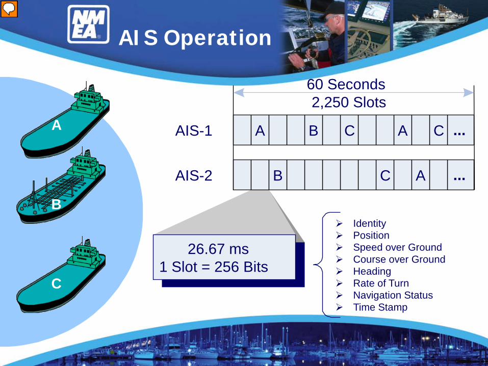
AIS Operation
A ...ACB
...CB
C
A
60 Seconds2,250 Slots
26.67 ms1 Slot = 256 Bits
AIS-1
AIS-2
Identity Position Speed over Ground Course over Ground Heading Rate of Turn Navigation Status Time Stamp
A
B
C

Class A AIS Schematic

Class B AIS Schematic

Class A broadcasts the following information every 2 – 10 seconds while underway and every 3 minutes while at anchor.
• Longitude - to 1/1000 minute • Latitude – to 1/1000 minute• Course over Ground – relative to true north 1/10th degree • True Heading – 0-359 degrees derived from gyro input• Time Stamp – the universal time to the nearest second the
information was generated
Messages

• MMSI Number – unique identification• Navigation Status – as defined by the COLREGS• Rate of Turn – right or left 0-720 degree/min • Speed over Ground – 1/10 knot resolution from 0–102 knots• Position Accuracy – differential GPS or other indication if
RAIM (Receiver Autonomous Integrity Monitoring) processing is being used
Messages

Class A broadcasts the following information every 6 minutes
• MMSI – same unique id number• IMO Number – unique id• Radio Call Sign– international call sign assigned to ship• Name - name of ship up to 20 characters are available• Type of Ship/Cargo – there is a table of possibilities• Dimensions of Ship – to the nearest meter
Messages
• Location of Reference Point – where reference point for position reports are located
• Type of Position Fixing Device – various options from differential GPS to undefined
• Draught of Ship – 1/10 -25.5 meter (note “air draught is not provided)
• Destination - 20 characters are available• Estimated Time of Arrival at Destination– month, day,
hour, minute in UTC
Messages

Class B broadcasts the following information every 30 seconds if traveling in excess of 2 knots and every 3 minutes slower than 2 knots
• Longitude - to 1/10000 minute • Latitude – to 1/10000 minute• True Heading – 0-359 degrees derived from gyro input (if
available)• Time Stamp – the universal time to the nearest second the
information was generated• DSC Receiver Installed – Y/N
Messages

• MMSI Number – unique identification• Speed over Ground – 1/10th resolution from 0 to 102 knots• Position Accuracy – differential GPS or other indication if
RAIM (Receiver Autonomous Integrity Monitoring) processing is being used
• Course of Ground – relative to true north 1/10th degree
Messages
Class B broadcasts the following information every 6 minutes
• MMSI – same unique id number, links the data to the vessel• Radio Call Sign– international call sign assigned to ship• Name - name of ship, 20 characters are available• Vendor ID number• Type of Ship/Cargo – there is a table of possibilities• Dimensions of Ship – to the nearest meter• Location of Reference Point – where reference point for
position reports are located
Messages

Installation
SN Circular 227 – AIS Installations
• Drawings• VHF Antenna Placement• Cable Types• GNSS Antenna Placement• Power Sources• Pilot Plug• Interfacing• Programming

Drawings
There should be the following documentation for a new AIS installation:
1 – Antenna layout showing the placement of the AIS related antennas with respect to the others.
2 – AIS arrangement in the Pilothouse showing component locations
3 – A one line Block diagram showing the AIS, its power supply(s), pilot plug, antennas. Cable types and circuit breaker locations are suggested.
VHF Antennas
An AIS is fundamentally a VHF-FM transceiver with a companion GPS antenna input
• A very important difference on the VHF side is:
The normal transmit frequencies are on the high end ofthe VHF-FM band (@ 162 mhz).
Because of this, the standard marine VHF antennas are not manufactured for optimum performance at those transmitter frequencies.

VHF Antennas
Solution
Make sure that you supply an antenna whosebandwidth covers the AIS frequencies.
You want to maximize your effective radiated power wherever you can and that starts with your antenna.
(A = 12.5 watts and B = 2 watts!)

VHF Antennas
• VHF Antenna– Possibly Integrated GPS
Antenna
• 6’ Feet from Conductive Objects
• Ideally 6’ Directly above or below VHF
• Otherwise 30’ Horizontal Separation
6'Minimum
Main VHFAntenna
AIS VHFAntenna

Antenna Location

Antenna Location

Coax Cables
1 - The recommendation is to use RG214 coax which is the double silver shielded coax. In fact, the loss of this cable vs. RG213 is the same (2.3 db for 100 feet @ 150 mhz), however, the shielding of the 214 is about 2 points better (95% vs. 97%).
2 – The loss of RG-58 is 6 db per 100 feet and its shielding is 93%.
Point – go for the bigger cable whenever you can and if you suspect shielding issues, use a foil + shield cable.
GNSS Antennas
Simply put, the GPS antenna needs to be installed at the highest point that you can. The recommendation is for a 360 degree view between the zenith and 5 degrees elevation. Lacking that availability, find the spot with the less likelyopportunity for blockage. In cases where you have a combined VHF/GPS antenna, that could very well be a compromise of access and servicing vs sightlines.

A
B
DC
GPS/ReferenceLocation
Distance (m)A 0 – 511 m
511 m = 511 m or GreaterB 0 – 511 m
511 m = 511 m or GreaterC 0 – 63 m
63 m = 63 m or GreaterD 0 – 63 m
63 m = 63 m or GreaterWhen Reference Location Unavailable, Use: A = B = C = D = 0
When Reference Location Unavailable, Vessel Dimensions in B, DA = C = 0, B ≠ 0, D ≠ 0

Power Sources
For Class A systems, the IMO recommendation SN Circ 227 isthat the unit should be connected to an Emergency Source.
For IMO vessels built after 1986, this means the Emergency Generator to which all the Communication and Navigation
equipment is to be connected to.
In addition, an Supplement to the Recommendation also requests that the AIS be connected to a UPS to ensure that the
switchover from Main to Emergency does not shut down the AIS

Power Sources
For Class B systems, there is no recommendation. However, I would suggest that the AIS be connected to the ‘last’ power source on the boat as should the VHF be as
well.
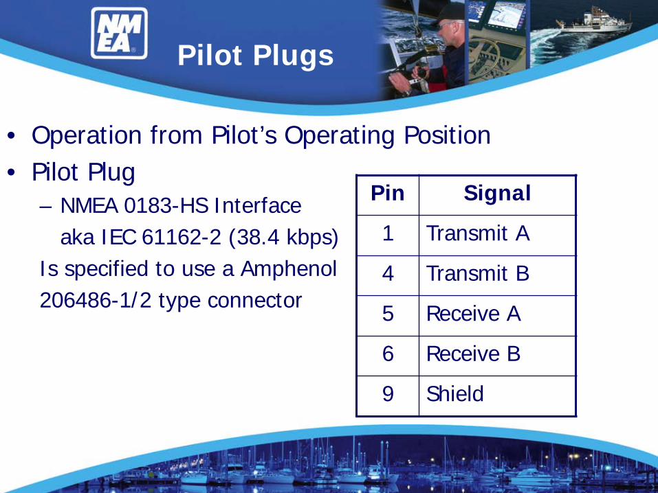
Pilot Plugs
• Operation from Pilot’s Operating Position• Pilot Plug
– NMEA 0183-HS Interfaceaka IEC 61162-2 (38.4 kbps)
Is specified to use a Amphenol206486-1/2 type connector
Pin Signal
1 Transmit A
4 Transmit B
5 Receive A
6 Receive B
9 Shield

Interfacing
NMEA 0183 or HS
Single WireNMEA 0183 HSNMEA 0183 HSNMEA 0183 HS
NMEA 0183 or HSNMEA 0183 or HS
AIS TransceiverOther Equipment
Sensor #1
Long Range
User Interface (Display/KBD)Sensor #3Sensor #2
Aux User / Pilot Interface
GPS Antenna VHF Antenna
BIIT

Interfacing
NMEA 2000®
Single Wire
NMEA 0183 HS
AIS TransceiverOther Equipment
BIIT
Aux User / Pilot Interface
Sensors and Displays
GPS Antenna VHF Antenna


Connections
Data NMEA 0183 Sentence Format
Reference Datum DTM
Positioning System:Time of Position, Latitude / Longitude, Position Accuracy
GNS,GLL
GGA, RMC
Speed over Ground (SOG) VBW VTG, OSD, RMC
Course over Ground (COG) RMC VTG, OSD
Heading HDT OSD
RAIM Indicator GBS
Rate of Turn (ROT) ROT
WGS84
BIIT (Built-in Integrity Test) Is Connected to an Alarm Relay

Programming
• Vessel Data– Maritime Mobile Service Identity (MMSI) Number *– IMO Vessel Number– Radio Call Sign *– Vessel Name *– Vessel Type *– GPS Antenna Location/Reference Position *– Type of Navigational Input (GPS, GLONASS, other)– ROT fitted (Y/N)
WebResources
• http://www.imo.org• http://www.vesseltracker.com/app
• http://www.navcen.uscg.gov
