automatic guitar tuner - ucf department of eecs · trenton ahrens, alex capo, ernesto wong 5-1-2015...
TRANSCRIPT

Trenton Ahrens, Alex Capo, Ernesto Wong 5-1-2015
University of Central Florida
Automatic Guitar Tuner Group 1

EEL4919 Fall 2014 Group 1 - Trenton Ahrens, Alex Capo, Ernesto Wong
i
Table of Contents 1 Executive Summary ....................................................................................... 1
2 Project Description ......................................................................................... 2
2.1 Motivation ................................................................................................ 2
2.2 Objectives ................................................................................................ 3
2.2.1 Tuning Time ...................................................................................... 3
2.2.2 Accuracy ........................................................................................... 3
2.2.3 Convenience ..................................................................................... 4
2.2.4 Budget .............................................................................................. 4
2.2.5 Experience ........................................................................................ 4
2.2.6 Knowledge Gain................................................................................ 4
2.3 Project Requirements and Specifications ................................................ 4
2.3.1 Accuracy ........................................................................................... 5
2.3.2 Tuning Preference ............................................................................ 5
2.3.3 Time .................................................................................................. 5
2.3.4 User friendly ...................................................................................... 5
2.3.5 Environment ...................................................................................... 5
2.3.6 Power ................................................................................................ 5
2.3.7 PCB .................................................................................................. 5
3 Research ........................................................................................................ 6
3.1 Relevant Technology ............................................................................... 6
3.1.1 Gibson Min-ETune ............................................................................ 6
3.2 Similar Reference Ideas .......................................................................... 6
3.2.1 "The Mechanix" Guitar Tuner - Cornell University ............................. 7
3.2.2 "Tune Squad" SMARTune - Calvin College ...................................... 7
3.3 4-String Bass Guitar Tuning .................................................................... 7
3.4 Motors ................................................................................................... 10
3.4.1 Servo Motors .................................................................................. 10
3.4.2 Stepper Motors ............................................................................... 11
3.4.3 DC Motor ........................................................................................ 11
3.5 Pickups .................................................................................................. 13
EEL4919 Fall 2014 Group 1 - Trenton Ahrens, Alex Capo, Ernesto Wong
ii
3.5.1 Magnetic Pickups ............................................................................ 13
3.5.2 Polyphonic Pickups ......................................................................... 14
3.5.3 Piezoelectric Pickups ...................................................................... 14
3.5.4 Humbuckers .................................................................................... 16
3.6 Microcontroller ....................................................................................... 17
3.6.1 Arduino Due .................................................................................... 17
3.6.2 BeagleBone .................................................................................... 17
3.6.3 MSP430 .......................................................................................... 18
3.6.4 PIC Microcontrollers ........................................................................ 18
3.6.5 Atmel AVR ...................................................................................... 19
3.7 Signal Processing .................................................................................. 19
3.7.1 Fast Fourier Transform ................................................................... 20
3.7.2 Wavelet Transform .......................................................................... 20
3.7.3 Goertzel Algorithm .......................................................................... 21
3.7.4 Analog to Digital Converter ............................................................. 22
3.8 Power Source ........................................................................................ 22
3.8.1 Batteries .......................................................................................... 23
3.8.2 Power Supply .................................................................................. 25
3.9 User Interface ........................................................................................ 25
3.9.1 Mobile operating system and application ........................................ 25
3.9.2 Bluetooth Specs .............................................................................. 27
3.9.3 Bluetooth Protocol Stack ................................................................. 30
3.10 Encoders ............................................................................................ 33
3.11 H-Bridge ............................................................................................. 34
4 Hardware and Software Design ................................................................... 35
4.1 Block Diagrams ..................................................................................... 35
4.1.1 Overall System Architecture ........................................................... 35
4.1.2 Power Distribution ........................................................................... 36
4.1.3 Hardware ........................................................................................ 37
4.1.4 Bluetooth Connection ...................................................................... 38
4.1.5 User Interface ................................................................................. 38

EEL4919 Fall 2014 Group 1 - Trenton Ahrens, Alex Capo, Ernesto Wong
iii
4.1.6 Microcontroller ................................................................................ 39
4.1.7 Tuning Mechanism (Electrical) ........................................................ 40
4.1.8 Tuning Mechanism (Mechanical) .................................................... 41
4.2 Hardware ............................................................................................... 42
4.2.1 Pickups ........................................................................................... 42
4.2.2 Motor Design .................................................................................. 43
4.2.3 ROB-12472 ..................................................................................... 45
4.2.4 Black & Decker Li2000 .................................................................... 45
4.2.5 Decision .......................................................................................... 46
4.2.6 H-Bridge Design.............................................................................. 46
4.2.7 Encoder Design .............................................................................. 48
4.2.8 Microcontroller ................................................................................ 50
PIC16F1719 ....................................................................................................... 54
4.2.9 Bluetooth Module ............................................................................ 54
4.2.10 PCB ............................................................................................. 56
4.2.11 Mobile Device .............................................................................. 60
4.3 Software ................................................................................................ 60
4.3.1 Mobile Application ........................................................................... 60
4.3.2 Signal Processing Algorithm ........................................................... 62
4.4 Integration of Hardware and Software ................................................... 63
4.4.1 Communication Protocol ................................................................. 63
4.4.2 Microcontroller Programming .......................................................... 65
4.5 Power Design ........................................................................................ 65
4.5.1 Overall Power Circuitry ................................................................... 65
4.5.2 Adafruit 6xAA Battery Pack Holder ................................................. 66
4.5.3 Adafruit 4xAA Battery Pack Holder ................................................. 66
4.5.4 Alkaline 9 Volt Battery ..................................................................... 66
4.5.5 Lithium Ion Polymer Battery ............................................................ 66
4.5.6 Decision .......................................................................................... 67
5 Prototyping ................................................................................................... 67
5.1 Parts Acquisition .................................................................................... 67

EEL4919 Fall 2014 Group 1 - Trenton Ahrens, Alex Capo, Ernesto Wong
iv
5.1.1 Funding ........................................................................................... 68
5.1.2 Vendors .......................................................................................... 68
5.2 Construction .......................................................................................... 68
5.2.1 Motor Prototyping ............................................................................ 68
5.2.2 H-Bridge Prototyping ....................................................................... 68
5.2.3 Encoder Prototyping ....................................................................... 68
5.2.4 Power Prototyping ........................................................................... 69
5.2.5 Microcontroller ................................................................................ 69
5.2.6 HC-05 to MSP430 ........................................................................... 69
5.2.7 Mobile Application ........................................................................... 70
5.3 PCB Vendor .......................................................................................... 70
5.3.1 OSH Park ........................................................................................ 70
5.3.2 4PCB .............................................................................................. 71
5.3.3 Software .......................................................................................... 71
5.4 Coding ................................................................................................... 71
5.4.1 Android SDK ................................................................................... 71
5.4.2 Mobile Application GUI ................................................................... 72
5.4.3 Bluetooth Functionalities ................................................................. 72
6 Testing ......................................................................................................... 76
6.1 Safety .................................................................................................... 76
6.1.1 Soldering Iron ................................................................................. 76
6.1.2 Power Tools .................................................................................... 76
6.1.3 Electrical components ..................................................................... 76
6.1.4 Bluetooth Radiation ......................................................................... 77
6.2 Testing Environment.............................................................................. 77
6.2.1 Test Procedure ............................................................................... 77
6.2.2 Data Logging .................................................................................. 79
6.3 PCB Testing .......................................................................................... 79
7 Administrative Content ................................................................................. 80
7.1 Milestones ............................................................................................. 80
7.1.1 Establishing an Idea ........................................................................ 80

EEL4919 Fall 2014 Group 1 - Trenton Ahrens, Alex Capo, Ernesto Wong
v
7.1.2 The Research Process ................................................................... 81
7.1.3 Design ............................................................................................. 81
7.1.4 Prototyping and Testing .................................................................. 81
7.2 Budget ................................................................................................... 82
8 Summary and Conclusion ............................................................................ 87
9 Appendices ..................................................................................................... i
9.1 Appendix A – References ......................................................................... i
9.2 Appendix B – Copyright Permissions .......................................................ii

EEL4919 Fall 2014 Group 1 - Trenton Ahrens, Alex Capo, Ernesto Wong
1
1 Executive Summary This project associates the expression of music as art form. The expression is a complex arrangement of frequencies in the form of sound that is pleasant to the ears. It can be expressed in many forms and can be derived from various origins using pitch, harmony, melody, and tempo. With modern technology, we are able to create, evaluate and express music like never before. It is an evolving art form, constantly changing over time. The tools and instruments needed to produce music incorporate sound frequencies needed to properly function. This includes having the correct pitch of notes, or tuning, set on a particular instrument. Based on how an instrument is played, a vast number of playing styles can be expressed by the player. This project aims to assist in creating music that is aesthetic. When it comes to composing and appreciating music, it is necessary to have order within the notes played. Humans need to hear the correct assembly of pitch along with tempo, harmony, and melody in order to find pleasure in the music heard. Music can otherwise sound unpleasant. This project will explore the science and technology behind sound. This project aims to look and explore the attributes of sound, mainly frequency. As mentioned before, in order to find music pleasurable, the right pitch must be set when composing music with an instrument. The proper tuning of notes will allow the player to make „good‟ music. This project will use modern technology to analyze and correct the pitch of strings on a bass guitar with accuracy and minimal effort. This project consists of five subsystems. These include the pickups, the microcontroller, the motors, the power supply, and user interface. Together these subsystems will all work together to achieve the goal of a self-tuning guitar with the computer and electrical engineering skills and knowledge to assist. For the flow of operation, the user will interact with the user interface through a mobile smartphone application. The settings and preferences selected by the user will be communicated via Bluetooth to the microcontroller. The pickups on the guitar will read the frequency on the string be plucked and the information will be analyzed by the microcontroller. Based on the user input of tuning preference, the microcontroller will send an output to the motors intended to control the tension of the strings. The motors will either tighten or loosen the string and therefore adjust the pitch of the note correlating the string being plucked. During this process, the pickups will continually capture the frequency of the string and send information to the microcontroller. When the desired pitch has been reach, the tightening or loosening of the strings will cease. The overall process is then repeated for the next string. This project will challenge the team members to apply engineering skills. The team will apply their knowledge and acquire new engineering skills through the design and testing process. Planning, management, the procedure for testing, and safety will be emphasized and practiced to achieve optimal results.

EEL4919 Fall 2014 Group 1 - Trenton Ahrens, Alex Capo, Ernesto Wong
2
2 Project Description The following sections will outline the details of the project as a whole. This was important in order to give the user a good starting idea of how the project came to be, as well as what the goals of the project are.
2.1 Motivation Upon brainstorming senior design ideas, the group struggled to compromise and commit to one idea at first. Although they were still in the early stage of the semester, making timely decisions came to be a factor. The group would meet time after time to get to know each other personally as well as become more comfortable with each other‟s presence and engagement in brainstorming as a team. Days would go by as they slowly got to know each other, sharing common interests, likes and dislikes. Soon enough, a realization that all member enjoy music with a passion occurred. It was recognized that two of the members both have experience playing guitar and have a passion for playing, with a third member who is avid in music produced with guitar playing. The team took advantage of this shared interest of guitar playing and made the next step upon reaching a compromise for a senior design idea. The group established a common basis for their senior design and made their first steps to reaching a final idea for a project. With this new kick start of motivation, the team began to narrow their brainstorming ideas. Through continuous brainstorming sessions, of course the team wanted to incorporate hardware and software into the project. They had a desire to apply their knowledge of engineering acquired through years of education and combine it with their passion for guitar playing. Through lectures in Senior Design, the team realized hardware and software components are expected in the project. Our group continued to narrow down ideas and once again, they compromised on another idea. As musicians, it is desired to have instruments that are functioning properly. However, problems can arise with the instruments that can conflict with producing music. One problem that was recognized that can occur is having an instrument be out of tune. The musicians would have to adjust his or her tuning of the instrument in order to continue producing music. The group came together once again and decided to capitalize this idea of problem solving. The team envisioned an automated process for tuning a bass guitar. As the team got closer and closer to a final Senior Design project idea, time was then spent on research for automated tuning processes for guitars. Information that was researched were shared with the group and some more brainstorming sessions were taken place. It was then recognized that the idea was challenging but also feasible. Base on the information gathered, the team slowly began to piece to together the components and subsystems necessary to accomplish the goal of a self-tuning bass guitar.

EEL4919 Fall 2014 Group 1 - Trenton Ahrens, Alex Capo, Ernesto Wong
3
A compromise on the idea of a mounted device on a guitar was made after further sharing of ideas and information. The group was set on creating a device that will automatically tune a bass guitar. Through the early stages of research, the team came across similar project ideas done in the past. Knowing they had reference material to assist in the design escalated the motivation to pursue the idea of a self-tuning bass guitar. Upon further understanding of what is expected for this idea to be successful, the team recognized that they would have to learn some new skills in order to accomplish the goal. Within the group, there is a yearning for preparation of their future careers. The group wanted to be able to get something out of this project that they can take with them after graduation. The group craved the knowledge and skills needed for their future careers. One member in particular has an interest in wireless communication. It was ideal to incorporate wireless technology into the project by adding a Bluetooth feature for the user interface and microcontroller. Another member has adequate experience with microcontrollers, which is ideal, for it is the backbone of the entire automated design. The third member has a deep interest in physical electrical components, soldering and wiring. He is also motivated to tackling the mechanical components of the design. Overall, every member within the group is motivated to creating an automatic guitar tuner. The team is devoted to taking on the challenges and hardships of this project, knowing something will be gained at the end.
2.2 Objectives The following information will contain the team objectives that will need to be met in order to have the desired functionality from the Automatic Guitar Tuner.
2.2.1 Tuning Time The team decided that the time it should take for each individual string to be properly tuned should take no more than 30 seconds. This gives the user the ability to change the pitch on each string in only a couple of minutes. Experienced guitarists are able to change their settings in a couple of minutes if not less, which means our timing should convenience them in that they will not have to manually do so. However for the beginner, this manual tuning time may be more drawn out. Not only will this speed up the beginners tuning time, but it will also accelerate the learning process of being able to recognize each specific desired pitch.
2.2.2 Accuracy In order for the system to be valuable, the accuracy for each individual setting must be within a certain percentage of difference from the exact desired pitch. The term used to describe this precise measurement is the "just noticeable

EEL4919 Fall 2014 Group 1 - Trenton Ahrens, Alex Capo, Ernesto Wong
4
difference," also referred to as the "difference threshold" or "least perceptible difference." The JND for the human ear on a guitar string is about + /- 5 cents from the correct value.
2.2.3 Convenience In order to maintain a comfortable playing posture, the system should be small enough that it does not interfere with the user while performing. That means that the motors mounted on the head of the guitar and the circuitry and wiring that will be on the guitars base must be small enough that it does not affect the user while playing. In order to achieve this, the team must come up with a convenient, yet feasible design to apply to the bass guitar.
2.2.4 Budget In order to replicate the design, the components to be used must be affordable and portable. It must be affordable in means that will meet the provided budget donated by Boeing. The budget given for the team must be spent on required parts for the design, and because the value of said budget is not too substantial, much thought must be put into each part before acquisition. Therefore much research must be done in order to select the most suitable component for the system. Putting effort into research on each individual part will provide good experience that will be repeated much in each member's future career.
2.2.5 Experience The experience that will be obtained by completing this project may be the most important objective. Not only will it provide hands on experience when piecing together the final product, but the experience with the design of the entire system is the most important of all. Usually engineers work together in a team environment throughout their entire career, so performing this task is the perfect jump start to entering the world for each member.
2.2.6 Knowledge Gain Each member of the group will benefit from the project equally. Though each member has their own specific assignment to focus on, all members will gain a further understanding of each subsystem being used. Because each subsystem is an electrical component of some form, completing the project will provide substantial information that will be carried on into each member‟s future. All of which are applicable to possible future careers which will be found beneficial to each member.
2.3 Project Requirements and Specifications This section defines the projects requirements and specifications that need to be met in the final design.
EEL4919 Fall 2014 Group 1 - Trenton Ahrens, Alex Capo, Ernesto Wong
5
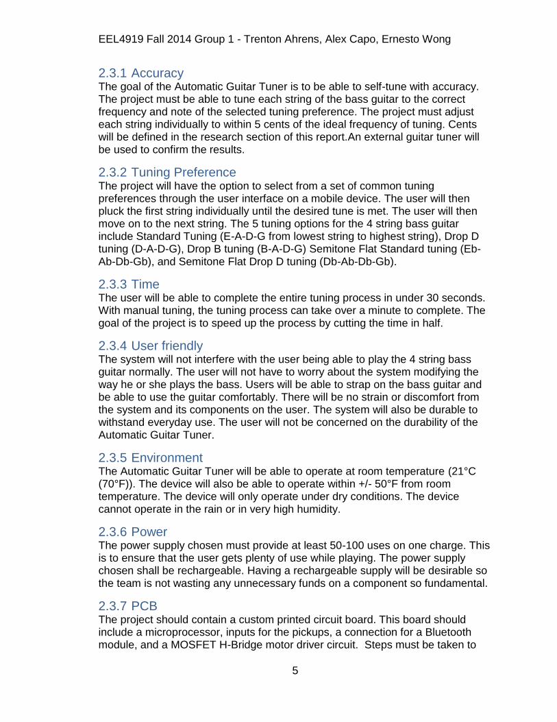
2.3.1 Accuracy The goal of the Automatic Guitar Tuner is to be able to self-tune with accuracy. The project must be able to tune each string of the bass guitar to the correct frequency and note of the selected tuning preference. The project must adjust each string individually to within 5 cents of the ideal frequency of tuning. Cents will be defined in the research section of this report.An external guitar tuner will be used to confirm the results.
2.3.2 Tuning Preference The project will have the option to select from a set of common tuning preferences through the user interface on a mobile device. The user will then pluck the first string individually until the desired tune is met. The user will then move on to the next string. The 5 tuning options for the 4 string bass guitar include Standard Tuning (E-A-D-G from lowest string to highest string), Drop D tuning (D-A-D-G), Drop B tuning (B-A-D-G) Semitone Flat Standard tuning (Eb-Ab-Db-Gb), and Semitone Flat Drop D tuning (Db-Ab-Db-Gb).
2.3.3 Time The user will be able to complete the entire tuning process in under 30 seconds. With manual tuning, the tuning process can take over a minute to complete. The goal of the project is to speed up the process by cutting the time in half.
2.3.4 User friendly The system will not interfere with the user being able to play the 4 string bass guitar normally. The user will not have to worry about the system modifying the way he or she plays the bass. Users will be able to strap on the bass guitar and be able to use the guitar comfortably. There will be no strain or discomfort from the system and its components on the user. The system will also be durable to withstand everyday use. The user will not be concerned on the durability of the Automatic Guitar Tuner.
2.3.5 Environment The Automatic Guitar Tuner will be able to operate at room temperature (21°C (70°F)). The device will also be able to operate within +/- 50°F from room temperature. The device will only operate under dry conditions. The device cannot operate in the rain or in very high humidity.
2.3.6 Power The power supply chosen must provide at least 50-100 uses on one charge. This is to ensure that the user gets plenty of use while playing. The power supply chosen shall be rechargeable. Having a rechargeable supply will be desirable so the team is not wasting any unnecessary funds on a component so fundamental.
2.3.7 PCB The project should contain a custom printed circuit board. This board should include a microprocessor, inputs for the pickups, a connection for a Bluetooth module, and a MOSFET H-Bridge motor driver circuit. Steps must be taken to
EEL4919 Fall 2014 Group 1 - Trenton Ahrens, Alex Capo, Ernesto Wong
6
ensure that the H-Bridge is isolated from the processor as driving motors could cause noise and large voltage spikes. The layout of the board will be determined once all components have been specified
3 Research The following sections will outline the majority of the research done for the project. The group split up the workload up into thirds in order to obtain as much knowledge as possible. When the team collaborated they shared what they had learned on their own with the rest of the team. It was decided that once the research portion had been completed, thought would then be put into the particular components to be purchased for the project.
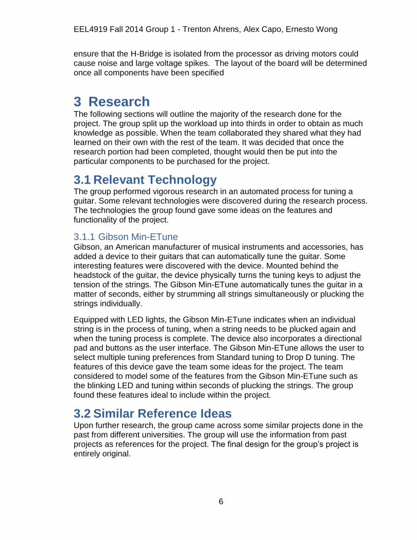
3.1 Relevant Technology The group performed vigorous research in an automated process for tuning a guitar. Some relevant technologies were discovered during the research process. The technologies the group found gave some ideas on the features and functionality of the project.
3.1.1 Gibson Min-ETune Gibson, an American manufacturer of musical instruments and accessories, has added a device to their guitars that can automatically tune the guitar. Some interesting features were discovered with the device. Mounted behind the headstock of the guitar, the device physically turns the tuning keys to adjust the tension of the strings. The Gibson Min-ETune automatically tunes the guitar in a matter of seconds, either by strumming all strings simultaneously or plucking the strings individually.
Equipped with LED lights, the Gibson Min-ETune indicates when an individual string is in the process of tuning, when a string needs to be plucked again and when the tuning process is complete. The device also incorporates a directional pad and buttons as the user interface. The Gibson Min-ETune allows the user to select multiple tuning preferences from Standard tuning to Drop D tuning. The features of this device gave the team some ideas for the project. The team considered to model some of the features from the Gibson Min-ETune such as the blinking LED and tuning within seconds of plucking the strings. The group found these features ideal to include within the project.
3.2 Similar Reference Ideas Upon further research, the group came across some similar projects done in the past from different universities. The group will use the information from past projects as references for the project. The final design for the group‟s project is entirely original.

EEL4919 Fall 2014 Group 1 - Trenton Ahrens, Alex Capo, Ernesto Wong
7
3.2.1 "The Mechanix" Guitar Tuner - Cornell University The project entitled “The Mechanix” Guitar Tuner is one of the projects the team came across during research. This project came from Cornell University and was done by group of guitar enthusiasts. The group recognized the similarities within this project to the desired features, functionalities and requirements of the Automatic Guitar Tuner.
According to the website, the Mechanix is a motorized guitar tuner for 6 string, fixed bridge electric and acoustic guitars. The website, however, is not very detail oriented. The group noticed some missing information such as how the device is mounted or a picture of the final design. The group still has access to various information, from the frequency of each string for Standard tuning to the source code used in the software. In comparison, the Mechanix and Automatic Guitar Tuner both achieve the same goal. The Mechanix guitar tuner can be used for both electric and acoustic guitars. The Automatic Guitar Tuner, on the other hand, will be fixed in place on the headstock of a bass guitar.
3.2.2 "Tune Squad" SMARTune - Calvin College The project entitled “Tune Squad” SMARTune is another project the team stumbled upon during the research process. This project originated from Calvin College and was also done by a team of avid guitar players. Upon researching through their website, the team found various information pertaining to the SMARTune. The group discovered that the SMARTune uses a standard, 4 string bass guitar. The SMARTune is mounted and fixed in place on the headstock of the bass and is not interchangeable. The SMARTune consists of 5 subsystems which operate together to achieve the automatic tuning goal. The group discovered the various aspects of the SMARTune and decided to model some of the functionalities and features into the Automatic Guitar Tuner.
According to the website, the objectives for SMARTune include tuning within a “just noticeable difference,” optimized tuning process to be complete within 15 seconds or less, fully integrate onto a bass guitar, and allow the user to select a range of tuning preferences. The group decided to model the objectives of the SMARTune into the Automatic Guitar Tuner as well as adding some additional requirements and objectives. In addition, the Automatic Guitar Tuner will allow the user to use a mobile device as the user interface through Bluetooth communication. The Automatic Guitar Tuner will also allow the user to operate the bass guitar without any interference of the system.
3.3 4-String Bass Guitar Tuning Each string on any stringed instrument must be tuned to the correct pitch, or frequency, in order for the user to play the instrument properly. Each string is tuned to a certain frequency that corresponds to the note. Below lists the correct frequencies with the corresponding note for a 4-string bass guitar in Standard tuning.

EEL4919 Fall 2014 Group 1 - Trenton Ahrens, Alex Capo, Ernesto Wong
8
Standard Tuning For a 4 String Bass Guitar
String Note Frequency (Hz)
1 (thinnest) G 98
2 D 73.42
3 A 55
4 (thickest) E 41.2
Table 1
In music, an interval is the difference between two frequencies. Musical intervals can be perceived by the ear and is defined by a ratio of frequencies. The ear can easily distinguish and is sensitive to these ratios of frequencies. When two notes are played, the ear can recognize an interval if any. The easiest interval to recognize is an octave, which is a 2:1 ratio of frequencies. An octave is the same note being played just at a higher pitch than the other. For example, a note with a frequency of 100Hz and another note with a frequency of 200 Hz are described as an octave.
Frequency Ratios
Table 2
Within musical intervals are units of pitch called cents. By definition, there are 100 cents in a semitone or minor second (from C to C#) and therefore 1200 cents in an octave. Since there are 1200 cents in an octave, one can see the power of 2 relationship when calculating frequency in terms of cents. The advantage of using cents notation is that it expresses the same musical interval throughout, regardless of the range of frequency [1].
Interval Frequency Ratio
Minor second 16:15
Major second 9:8
Minor third 6:5
Major third 5:4
Perfect fourth 4:3
Diminished fifth 7:5
Perfect fifth 3:2
Minor sixth 8:5
Major sixth 5:3
Minor seventh 7:4
Major seventh 15:8
Octave 2:1

EEL4919 Fall 2014 Group 1 - Trenton Ahrens, Alex Capo, Ernesto Wong
9
𝑓2
𝑓1= 2
¢1200
𝑙𝑛 𝑓2
𝑓1 =
¢
1200ln 2 or ¢ = 1200
𝑙𝑛 𝑓2𝑓1
𝑙𝑛 (2)
To the human ear, a just noticeable difference (JND) is equal to about 5 cents, meaning the ear can only hear a difference of about 5 cents.
For a bass guitar, the diameter of each string, or string gauge, affects the tone produced when plucking. String gauges range from weight depending on the user‟s desired tone. Each string gauge is measured in thousandths of an inch. The heavier or thicker the string, the more deep or lower the tone will produce when played. Below is a list of common gauges for a 4 string bass guitar.
String Gauges
Weight Scale (4) E string (3) A string (2) D string (1) G string
Extra Light 0.095 0.075 0.055 0.035
Light 0.100 0.080 0.060 0.040
Medium 0.105 0.085 0.065 0.045
Heavy 0.110 0.090 0.070 0.050
Extra Heavy 0.115 0.095 0.075 0.055
Table 3
The construction of each string also determines the tone of the sound produced. The most common bass strings have an outer winding wrapped around a steel core wire usually made of stainless steel or nickel. There are 3 popular styles of winding for electric bass strings: Roundwound, Flatwound, and Groundwound [2].
Roundwound: Most popular of all string windings. It produces a bright, louder sound. Rigged texture, which can wear down frets over time.
Flatwound: Smoother feel that produces a mellow, rounder tone. Less fretboard wear than Roundwound.
Groundwound: a hybrid of Roundwound and Flatwound. Offers some brightness of Roundwound with less wear on the frets.
Cross-Section Diagram

EEL4919 Fall 2014 Group 1 - Trenton Ahrens, Alex Capo, Ernesto Wong
10
Figure 1
3.4 Motors This portion of the document covers the means in which the gears are controlled. In order to tune the guitar, the team must come to a conclusion of what the best way to turn the gears will be. There are different motor options available to do so and these options will be explored in the following subsections.
3.4.1 Servo Motors A servomotor is a rotary actuator that allows the user to obtain precise control of angular position, velocity and acceleration. This is done by pairing an appropriate motor to a position sensor that will provide feedback of the current position of the motor compared to its desired output. Many microcontrollers are capable of controlling the input and output of these motors and prove to be a valuable component to the project.
A servomotor is actually a servomechanism that uses a closed loop analysis in order to control the motors motion and desired position. The input signal can be either analog or digital, which will determine the position needed by the output. For the task at hand, analog signals will be read by the pickups that are to be mounted on the guitar. These signals will be fed into the systems microcontroller, and will then be attenuated accordingly.
The motor uses an encoder to provide position and speed feedback. For simplicity, only position feedback servomotors will be considered initially. These motors are said to be easier to control, and may be of enough precision for the teams design requirements. These types of motors take the current positioning of the output and compare it to the set position. If the output is off, an error is recorded. The motors will adjust according to the error, either forward or backward. Many samples will be taken and changes will be made until the error read by the encoder is zero. Once this is met, the guitar will be in tune.
There are more complex servomotors available that use speed, along with position, as a means of feedback. Because of this, the accuracy and timing of the
EEL4919 Fall 2014 Group 1 - Trenton Ahrens, Alex Capo, Ernesto Wong
11
motor can be greatly increased. The team aims for simplicity and low cost components, therefore these types of motors will only be considered if the position only feedback motors prove to be insufficient.
Servomotors seem to be a feasible option when it comes to tuning control of the guitar. If servomotors end up being the best choice for the team, different options will be looked into before making any final purchase decisions.
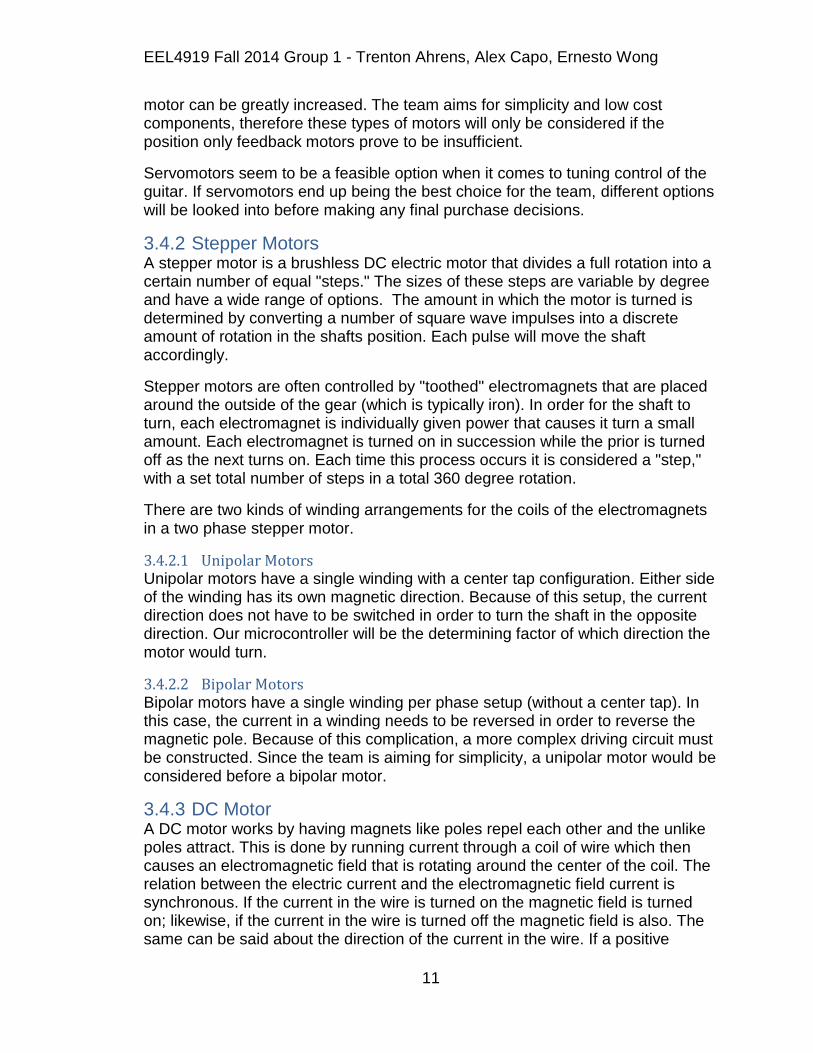
3.4.2 Stepper Motors A stepper motor is a brushless DC electric motor that divides a full rotation into a certain number of equal "steps." The sizes of these steps are variable by degree and have a wide range of options. The amount in which the motor is turned is determined by converting a number of square wave impulses into a discrete amount of rotation in the shafts position. Each pulse will move the shaft accordingly.
Stepper motors are often controlled by "toothed" electromagnets that are placed around the outside of the gear (which is typically iron). In order for the shaft to turn, each electromagnet is individually given power that causes it turn a small amount. Each electromagnet is turned on in succession while the prior is turned off as the next turns on. Each time this process occurs it is considered a "step," with a set total number of steps in a total 360 degree rotation.
There are two kinds of winding arrangements for the coils of the electromagnets in a two phase stepper motor.
3.4.2.1 Unipolar Motors Unipolar motors have a single winding with a center tap configuration. Either side of the winding has its own magnetic direction. Because of this setup, the current direction does not have to be switched in order to turn the shaft in the opposite direction. Our microcontroller will be the determining factor of which direction the motor would turn.
3.4.2.2 Bipolar Motors Bipolar motors have a single winding per phase setup (without a center tap). In this case, the current in a winding needs to be reversed in order to reverse the magnetic pole. Because of this complication, a more complex driving circuit must be constructed. Since the team is aiming for simplicity, a unipolar motor would be considered before a bipolar motor.
3.4.3 DC Motor A DC motor works by having magnets like poles repel each other and the unlike poles attract. This is done by running current through a coil of wire which then causes an electromagnetic field that is rotating around the center of the coil. The relation between the electric current and the electromagnetic field current is synchronous. If the current in the wire is turned on the magnetic field is turned on; likewise, if the current in the wire is turned off the magnetic field is also. The same can be said about the direction of the current in the wire. If a positive

EEL4919 Fall 2014 Group 1 - Trenton Ahrens, Alex Capo, Ernesto Wong
12
current is applied to the wire the magnetic field will turn in one direction, whereas when a negative current is applied to the wire the magnetic field will turn in
direction 180°.
The simplest form of a DC motor has a stationary set of two magnets in the stator with a series of either two or more windings of wire in the armature. The coil wire is wrapped in insulated stack slots around iron poles with the ends of the wires attached to the commutator. Also on the armature are mounting bearings which keep it centered on the motor and power shaft of the motor and commutator connections. The wire winding loops around the armature and uses either single or parallel wires that also wrap several times around the iron poles. The strength of the electromagnetic field is largely determined by the amount of current sent through the windings as well as the size of the wire and the material in which it is wrapped around. The selection powering on a particular coil will dictate the direction in which the electromagnetic field will permeate. By doing this, these rotating magnetic fields induced by the coils interact with the magnet fields of the stationary or electromagnets that are mounted on the stator. This interaction then creates a force on the armature that causes it to rotate. There are some situations that occur where the DC motor designs the stator to use electromagnets to create their magnetic field which can then allow greater motor control.
The commutator is the part of the armature that allows the coil to be activated. This is done typically by using two brushes that make a moving contact with the commutator. Recent designs of DC motors use brushless setups and instead use special electronics that will switch the current on and off. This is ideal because the user does not have to worry about the motors wearing out or creating sparks which can be harmful to the hardware.
The amount of speed at which these motors can rotate and torque they can produce is determined by the number of active fields in the stator and armature as well as what method of connection is used. The speed of the motor is directly proportional to the amount of voltage applied to the armature. Nowadays, this speed is variable by adding an adjustable resistance to the armature circuit or field circuit. Another way of adjusting the voltage seen by the armature is by cutting the voltage on and off in cycles, doing so thus causes a lower voltage to be transmitted to the armature and causes a reduced speed. DC motors output their highest torque at a low speeds and is exactly what will be necessary for the Automatic Guitar Tuner. The motor picked must be able to apply a substantial amount of torque but at a low rotational speed in order to accurately tune the frequency on each string. Not only do DC motors meet the projects rotational needs, but they are capable of being powered off batteries. With the power portion of the system being wireless, a battery will be integrated in the system already and can hopefully supply enough power to move the motors as well.
The topology of the connections between the stator and rotor is the driving factor on the speed and torque in which the motor can provide. There are three different types of connections: series, parallel (also known as shunt) and a
EEL4919 Fall 2014 Group 1 - Trenton Ahrens, Alex Capo, Ernesto Wong
13
compound connection, which is the combination of series and parallel connections. Each connection technique has its own unique characteristics in terms of different load torque and speed.
A series connection connects a DC power source in series to the armature and field windings. Doing this allows for a very high starting torque which is capable of moving large loads. An example of this motor would be one whose purpose is to move a train, the train being a very large load needs this type of a motor to operate. For the tuning pegs of the guitar, this type of motor may or may not be necessary. With a 36 lb-in torque requirement from the motor, the team would have to ensure that the motor would not damage the guitar by applying an excess amount of torque on the peg too fast. The motor speed for a series DC motor varies non-linearly to the size of the load, so if the load of the guitar was in a reasonable range for optimal performance of the motor, this could be a good choice.
A parallel/shunt DC motor has the armature and field windings connected in parallel to a DC source. This motor allows for better than average speed control even as the load size increases, but negates the large amount of starting torque that the series connection offers. The amount of torque required by the tuning pegs seems quite high, thus requiring a substantial amount of initial starting torque. The use of a parallel connection DC motor seems like a doubtful final decision in terms of parts acquisition.
The compound DC motor connects the armature and filed windings in both shunt and series connections. This intuitively gives both high starting torque and speed control of the motor. This type of motor could possibly be the perfect fit for the task at hand. The team will put serious thought into this classification of DC motors because it would offer the best possible outcome in terms of controlling the tuning mechanism for the Automatic Guitar Tuner.
3.5 Pickups The pickups on a guitar are responsible reading the mechanical vibration of the strings. The pickup is usually a transducer that will capture mechanical vibrations from the strings on the guitar, or instrument, and convert them to an electrical signal. These signals can then be amplified, modified, or recorded.
3.5.1 Magnetic Pickups Magnetic pickups are the most common and widely used pickups. A magnetic pickup consists of a permanent magnet wrapped with several thousand turns of copper wire. The permanent magnet creates a magnetic field. When a string vibrates it disturbs this magnetic field. This creates a change in magnetic flux which in turn induces a voltage in the coil. Magnetic pickups, specifically single coil pickups, can act as a directional antenna and can be prone to picking up "mains hum." Mains hum is caused by interference from power cables, power transformers, and sources of AC power.
EEL4919 Fall 2014 Group 1 - Trenton Ahrens, Alex Capo, Ernesto Wong
14
The alternating current can cause a change in magnetic flux in the pickups and induce a voltage. This causes interference and creates noise in the signal.
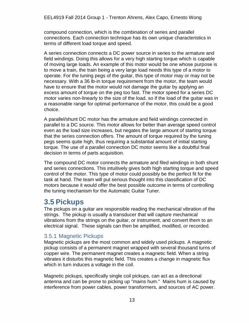
The output voltage of magnetic pickups usually varies between 100mV rms up to 1V rms on higher output pickups. An intense strum on all six strings of the guitar can induce voltage peaks of 5 volts on single coil magnetic pickups, and 10 volts on dual coil magnetic pickups. The higher outputs that can occur on high-output pickups are achieved by using stronger magnets thus creating more magnetic flux, and a higher output.
Single Coil Pickup
Figure 2
3.5.2 Polyphonic Pickups Polyphonic pickups are a type of passive pickups. Passive pickups are the most common type of pickups. They consist of wire wound around a magnet. They generate electric potential without requiring external circuitry or power. Their output is usually low as a result. Polyphonic pickups are used to produce separate signals for each individual string on a guitar. They consist of a separate wire wound magnet for each string. This allows the individual strings to be analyzed separately. Each string creates a signal in the closest pickup. However, a bleeding or cross-talk can occur due to the short distance between each pickup. However, on a bass guitar the strings are farther apart so less cross-talk between pickups occurs.
3.5.3 Piezoelectric Pickups Piezoelectric pickups are a type of active pickup. Active pickups require a source of additional power. This usually consists of batteries on the guitar. They also require additional circuitry to operate. This usually consists of a preamp, some

EEL4919 Fall 2014 Group 1 - Trenton Ahrens, Alex Capo, Ernesto Wong
15
active filtering, and an active EQ. The requirement of additional power results in a much higher output. They are less affected by the connectors, the length of the cable, the amplifier characteristics, and other forms of signal noise or degradation. Piezoelectric pickups are commonly used in semi-acoustic and acoustic guitars and some bases. They are sometimes used with, or instead of magnetic pickups. They are mounted differently than electric guitar pickups. They are usually mounted on the guitar body near the bridge as shown below. An advantage of Piezoelectric pickups is that they do not pick up any other magnetic field. This can be useful if a very clean sound or signal is required. Other types of pickups can pick up interference from nearby magnetic fields which can distort the signal. When using piezoelectric pickups, a preamp is usually required. Piezoelectric pickups have a very high output impedance. They can create a capacitance in series with a voltage source. As a result they need to have a buffer amplifier, or a preamp. This allows the maximum frequency response to be obtained from the pickups. Unlike Magnetic Pickups, which have a limited frequency response with an emphasis on mid-range, piezoelectric pickups have a flat frequency response and a very wide range of 10-100kHz. They also give larger amplitude signals from the strings. Due to the large amplitude the buffer requires a high voltage (around 9V), otherwise clipping or distortion can occur[3].
Piezoelectric Pickup Diagram
Figure 3
EEL4919 Fall 2014 Group 1 - Trenton Ahrens, Alex Capo, Ernesto Wong
16
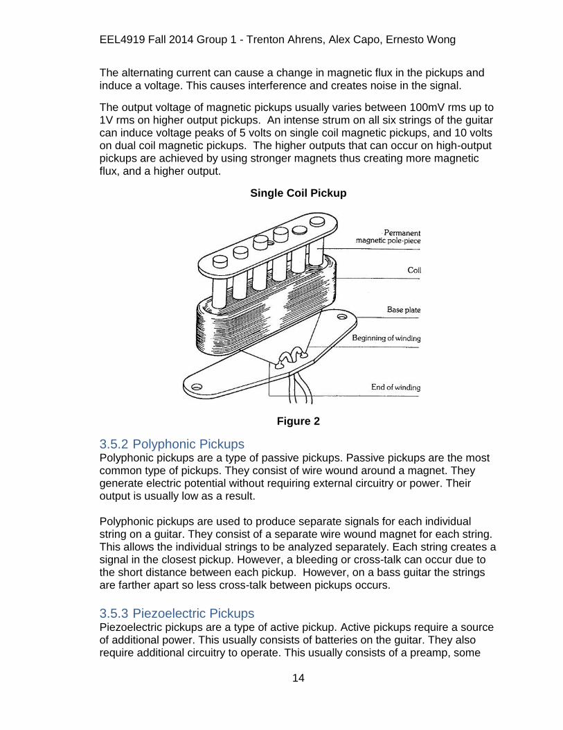
3.5.4 Humbuckers Single coil pickups can act like a directional antenna and can be prone to picking up mains hum(nuisance electromagnetic interference generated by electrical power cables, power transformers, and fluorescent light ballasts in the area) that is combined with the signal from the strings. Mains hum consists of a fundamental signal at a nominal 50 or 60 Hz, depending on local alternating current frequency, and usually some harmonic content. The changing magnetic flux caused by the mains current links with the windings in the pickup, which induces a voltage by transformer action. The pickups can also be sensitive to the electromagnetic field from nearby cathode ray tubes in video monitors or televisions, although this is less of a problem with modern LCD displays. A humbucking pickup, shown in the image below, is composed of two coils. Each coil is wound reverse to one another. However, the six magnetic poles are opposite in polarity in each winding. Since ambient hum from power-supply transformers, radio frequencies, or electrical devices reaches the coils as common-mode noise, it induces an electrical current of equal magnitude in each coil. Because the windings are reversed in each pickup coil, the electro-magnetic interference sine wave signals in each pickup are equal and opposite in phase, resulting in them canceling each other. However, the signal from the guitar string is doubled, due to the phase reversal caused by the out of phase magnets. The magnets being out of phase in conjunction with the coil windings being out of phase put the guitar string signal from each pickup in phase with one another. Therefore, the voltage of the signal is approximately doubled, if the two coils are connected in series.
Humbucker Diagram
Figure 4

EEL4919 Fall 2014 Group 1 - Trenton Ahrens, Alex Capo, Ernesto Wong
17
When wired in series, as is most common, the overall inductance of the pickup is increased, which lowers its resonance frequency and attenuates the higher frequencies, giving a tone with less treble than either of the two component single-coil pickups would give by themselves. Because the two coils are wired in series, the resulting signal that is output by the pickup is larger in amplitude, thus more able to overdrive the early stages of the amplifier. An alternative wiring places the coils in buck parallel. The equal common-mode mains hum interference cancels, while the string variation signal sums. This method has a more neutral effect on resonant frequency. The mutual capacitance is doubled (which if inductance were constant would lower the resonant frequency), and inductance is halved (which would raise the resonant frequency without the capacitance change). The net is no change in resonant frequency. This pickup wiring is rare, as guitarists have come to expect that humbucking 'has a sound', and is not neutral. On fine jazz guitars, the parallel wiring produces significantly cleaner sound, as the lowered source impedance drives capacitive cable with lower high frequency attenuation [4].
3.6 Microcontroller 3.6.1 Arduino Due The Arduino Due is an ARM based board. It has an Atmel 32 bit ARM Cortex M3 running at 84MHz. It has 4 high speed serial communication ports and 70 input/output pins. The Due also has 12 ADC inputs with 12-bit resolution. This is crucial for being able to process the signal received from the pickups on the guitar. This eliminates the possibility of using the Arduino Uno, since it does not have ADC inputs. The Arduino Due differs from other microcontrollers in that the maximum voltage that the I/O pins can tolerate is 3.3 volts, higher voltages such as 5 volts can damage the board.
The Due also has 12 PWM channels which will be required to control the motors when tuning the guitar. The board also has 512 kB of flash memory and 96 kB of SRAM. The Due has a DMA controller that can relieve the cpu from having to do memory intensive taksk. The size of the board is 102 mm by 53 mm. The Arduino Due is available for $49.95 from www.adafruit.com and $44.93 from www.amazon.com.
3.6.2 BeagleBone The Beaglebone Black has a Texas Instruments AM335X ARM Cortex A8 processor that runs at 1GHz. This is much faster than the Arduino or MSP 430 run at allowing for faster computation. It has 8 12-bit ADC's and 3 PWM channels. The Black has 512 MB of DDR3 memory and 4 kB of EEPROM. It has 4GB of eMMC on-board flash storage, 3D graphic accelerator, 2x PRU 32-bit microcontrollers. The Black has USB, Ethernet, HDMI outputs, and 2x 46 pin headers for connectivity.
EEL4919 Fall 2014 Group 1 - Trenton Ahrens, Alex Capo, Ernesto Wong
18
The BeagleBone Black is a very powerful board and is usually used with operating systems. It is very commonly used to run linux based software. It can run Debian, Android, Ubuntu, Cloud9 IDE, and other operating systems. As this project will not require running an operating system, the BeagleBone Black will most likely not be chosen.
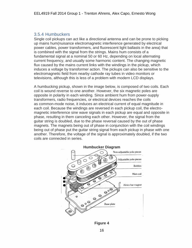
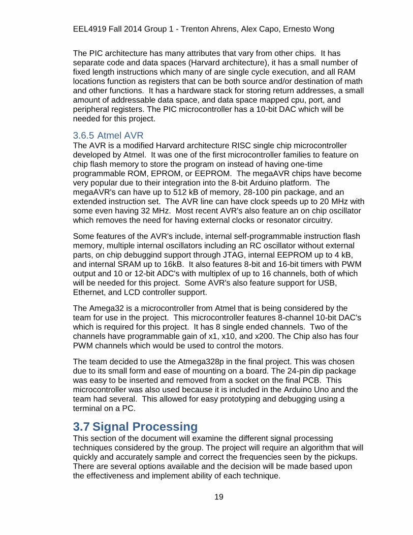
3.6.3 MSP430 The MSP 430 is a microprocessor family from Texas Instruments. They are a basic line of 16-bit microprocessors. They are typically very low cost and have very little power consumption. They are designed specifically for embedded use. The current drawn in idle mode can be less than 1 µA. The fastest processor speed available is 25 MHz allowing for less power consumption. The MSP 430 has six different low power modes that will turn off unneeded cpu's and clocks. They are capable of having wake up times of less than one microsecond. This allows the device to stay in sleep mode longer and reduce power consumption. The Texas Instruments MSP 430 line would be a great choice for this project. They have numerous choices with varying capabilities and use cases. Some of the features available on the MSP 430 line include; PWM, USART, internal oscillator, ADC's, 12-bit DAC, and USB.
Figure 5
3.6.4 PIC Microcontrollers The PIC microcontrollers are a family of chips of modified Harvard architecture made by Microchip Technology. The name PIC refers to Peripheral Interface Controller but is commonly shortened to PIC. The PIC controllers are very popular with industrial developers and hobbyists due to the low cost, wide availability, and extensive user base.
EEL4919 Fall 2014 Group 1 - Trenton Ahrens, Alex Capo, Ernesto Wong
19
The PIC architecture has many attributes that vary from other chips. It has separate code and data spaces (Harvard architecture), it has a small number of fixed length instructions which many of are single cycle execution, and all RAM locations function as registers that can be both source and/or destination of math and other functions. It has a hardware stack for storing return addresses, a small amount of addressable data space, and data space mapped cpu, port, and peripheral registers. The PIC microcontroller has a 10-bit DAC which will be needed for this project.
3.6.5 Atmel AVR The AVR is a modified Harvard architecture RISC single chip microcontroller developed by Atmel. It was one of the first microcontroller families to feature on chip flash memory to store the program on instead of having one-time programmable ROM, EPROM, or EEPROM. The megaAVR chips have become very popular due to their integration into the 8-bit Arduino platform. The megaAVR's can have up to 512 kB of memory, 28-100 pin package, and an extended instruction set. The AVR line can have clock speeds up to 20 MHz with some even having 32 MHz. Most recent AVR's also feature an on chip oscillator which removes the need for having external clocks or resonator circuitry.
Some features of the AVR's include, internal self-programmable instruction flash memory, multiple internal oscillators including an RC oscillator without external parts, on chip debuggind support through JTAG, internal EEPROM up to 4 kB, and internal SRAM up to 16kB. It also features 8-bit and 16-bit timers with PWM output and 10 or 12-bit ADC's with multiplex of up to 16 channels, both of which will be needed for this project. Some AVR's also feature support for USB, Ethernet, and LCD controller support.
The Amega32 is a microcontroller from Atmel that is being considered by the team for use in the project. This microcontroller features 8-channel 10-bit DAC's which is required for this project. It has 8 single ended channels. Two of the channels have programmable gain of x1, x10, and x200. The Chip also has four PWM channels which would be used to control the motors.
The team decided to use the Atmega328p in the final project. This was chosen due to its small form and ease of mounting on a board. The 24-pin dip package was easy to be inserted and removed from a socket on the final PCB. This microcontroller was also used because it is included in the Arduino Uno and the team had several. This allowed for easy prototyping and debugging using a terminal on a PC.
3.7 Signal Processing This section of the document will examine the different signal processing techniques considered by the group. The project will require an algorithm that will quickly and accurately sample and correct the frequencies seen by the pickups. There are several options available and the decision will be made based upon the effectiveness and implement ability of each technique.
EEL4919 Fall 2014 Group 1 - Trenton Ahrens, Alex Capo, Ernesto Wong
20
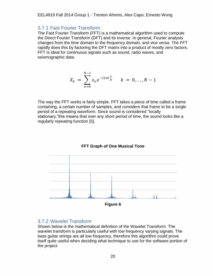
3.7.1 Fast Fourier Transform The Fast Fourier Transform (FFT) is a mathematical algorithm used to compute the Direct Fourier Transform (DFT) and its inverse. In general, Fourier analysis changes from the time domain to the frequency domain, and vice versa. The FFT rapidly does this by factoring the DFT matrix into a product of mostly zero factors. FFT is ideal for continuous signals such as sound, radio waves, and seismographic data.
𝑋𝑘 = 𝑥𝑛𝑒−𝑖2𝜋𝑘𝑛
𝑁
𝑁−1
𝑛=0
𝑘 = 0, . . . , 𝑁 − 1
The way the FFT works is fairly simple. FFT takes a piece of time called a frame containing, a certain number of samples, and considers that frame to be a single period of a repeating waveform. Since sound is considered "locally stationary,”this means that over any short period of time, the sound looks like a regularly repeating function [5].
FFT Graph of One Musical Tone
Figure 6
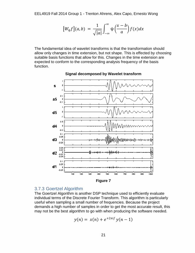
3.7.2 Wavelet Transform Shown below is the mathematical definition of the Wavelet Transform. The wavelet transform is particularly useful with low frequency varying signals. The bass guitar strings are all low frequency, therefore this algorithm could prove itself quite useful when deciding what technique to use for the software portion of the project.
EEL4919 Fall 2014 Group 1 - Trenton Ahrens, Alex Capo, Ernesto Wong
21
𝑊ѱ𝑓 (𝑎, 𝑏) = 1
𝑎 ѱ
𝑥 − 𝑏
𝑎 𝑓(𝑥)𝑑𝑥
∞
−∞
The fundamental idea of wavelet transforms is that the transformation should allow only changes in time extension, but not shape. This is effected by choosing suitable basis functions that allow for this. Changes in the time extension are expected to conform to the corresponding analysis frequency of the basis function.
Signal decomposed by Wavelet transform
Figure 7
3.7.3 Goertzel Algorithm The Goertzel Algorithm is another DSP technique used to efficiently evaluate individual terms of the Discrete Fourier Transform. This algorithm is particularly useful when sampling a small number of frequencies. Because the project demands a high number of samples in order to get the most accurate result, this may not be the best algorithm to go with when producing the software needed.
𝑦 𝑛 = 𝑥 𝑛 + 𝑒+2𝜋𝑖𝑓 𝑦 𝑛 − 1

EEL4919 Fall 2014 Group 1 - Trenton Ahrens, Alex Capo, Ernesto Wong
22
= 𝑥(𝑘)𝑒+2𝜋𝑖𝑓 (𝑛−𝑘)
𝑛
𝑘=−∞
= 𝑒+2𝜋𝑖𝑓𝑛 𝑥(𝑘)𝑒−2𝜋𝑖𝑓𝑘
𝑛
𝑘=0
3.7.4 Threshold Crossing The team decided to go with a method of threshold crossings to calculate the frequency in the final design. This is accomplished by calculating the period of the wave and determining the frequency. If the signal is increasing and crosses a midpoint (2.5V), it starts timing until it crosses that point again with a positive slope to calculate the period of the signal. The frequency is then calculated from that period and is used to determine if the string is in tune or not.
3.7.5 Analog to Digital Converter An analog to digital converter is a widely used electronic device that has multiple applications in every day engineering. The device will take in analog signals, which will be measured by some peripheral device, and convert that continuous signal into discrete digital values. Because the process involves quantization of the input, there will always be some naturally small error. The way this is done is by "sampling" many different periods rather than only doing one conversion at a time. ADC can be found as peripheral components on a lot of different microcontrollers, so we must pick one suitable for our design needs.
The analog to digital converters are a key part to the design. With the bass guitar having four strings, the microcontroller we choose must have at least four ADC inputs. The pickups will take analog signal inputs once the guitar string is strummed, and the ADC will take these signals and convert them to a digital values. Based on the analog signals received, the microcontroller attenuates the tension on each string accordingly.
3.8 Power Source This portion of the document will cover power options for the system. The system requires that the tuning mechanism shall be able to supply at least 50-100 uses on a single charge. With this being said, the team must explore feasible power supply components that will be able to make this happen. Along with the expected amount of uses, portability is a key factor also when designing the power supply. That means the route the team decides to take must also provide a light weight design.
The team‟s initial goal is to be able to provide power to each individual subsystem with just one source. In order to do this, a circuit design must be obtained in order to drop down or amplify the sources voltage to the appropriate amount required by each subsystem. Different suitable options will be considered when coming to a final decision on the systems means of power.

EEL4919 Fall 2014 Group 1 - Trenton Ahrens, Alex Capo, Ernesto Wong
23
3.8.1 Batteries A battery is a device that consists of one or more electromechanical cells that convert stored chemical energy into electric energy. Each battery cell has a positive and negative terminal, which are referred to as the cathode and anode respectively. Electrolytes are what allows ions to move between the electrodes and terminals, which allow electric current to flow out of the battery to the load.
Primary or disposable batteries are one time use batteries and are the most common type of battery used today. These batteries can be identified as the alkaline battery used for flashlights and many other hand held devices. Secondary or rechargeable batteries can be used multiple times due to their discharge and recharge ability. The electrodes in this case are able to be restored by reverse current during their charging process. Lead acid batteries used in cars are a prime example of a secondary battery. A secondary battery would be most useful to the team because it would deduct excess funds spent on the constant replacement of batteries during the prototyping process. For the means of the task at hand, a lithium ion battery would be the classification of battery used. The size of these batteries come in many different variations as well as their shape. There are batteries small enough to power something as small as a hearing aid and then ones big enough to power large computer data banks.
Batteries cell types have been changing over time and consist of varying chemical processes and designs ranging from galvanic cells, electrolytic cells, fuel cells and many others. A wet cell (also known as a flooded cell) battery got its name because it has a liquid electrolyte composition. Wet cells were used before dry cells and are commonly used as learning tools for electrochemistry. These batteries are capable of being built with commonly used laboratory supplies for demonstrations of these cells work. Wet cells are capable of being primary or secondary batteries. Car batteries are examples of wet cell batteries, however for portable devices are usually not used.
A dry cell battery uses a paste type electrolyte with only enough moisture to allow current flow. The advantage of using a dry cell versus a wet cell is that its orientation can take on any posture without spilling, because it does not contain any free liquid and makes it suitable for portable equipment. A dry cell battery would be the type of battery investigated if battery power is the option chosen. Dry cell batteries typically distribute 1.5 volts which may prove to be too minimal for the requirements of the project. However combining many of them in series could up the voltage output.
The battery performance can very different given certain circumstances. The load amount is the driving factor in the battery performance. Because more power may be drawn from the battery at certain times than others, a good battery performance is a must for the system. Temperature also plays a role in the performance of the battery, therefore optimal cooling conditions may need to be investigated in order to keep the system at a prime operating temperature. The
EEL4919 Fall 2014 Group 1 - Trenton Ahrens, Alex Capo, Ernesto Wong
24
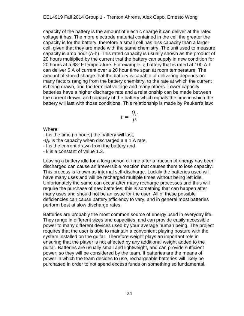
capacity of the battery is the amount of electric charge it can deliver at the rated voltage it has. The more electrode material contained in the cell the greater the capacity is for the battery, therefore a small cell has less capacity than a larger cell, given that they are made with the same chemistry. The unit used to measure capacity is amp hour (A-h). This rated capacity is usually shown as the product of 20 hours multiplied by the current that the battery can supply in new condition for
20 hours at a 68° F temperature. For example, a battery that is rated at 100 A-h can deliver 5 A of current over a 20 hour time span at room temperature. The amount of stored charge that the battery is capable of delivering depends on many factors ranging from the battery chemistry, to the rate at which the current is being drawn, and the terminal voltage and many others. Lower capacity batteries have a higher discharge rate and a relationship can be made between the current drawn, and capacity of the battery which equals the time in which the battery will last with those conditions. This relationship is made by Peukert's law:
𝑡 = 𝑄𝑃
𝐼𝑘
Where: - t is the time (in hours) the battery will last,
-𝑄𝑃 is the capacity when discharged a a 1 A rate, - I is the current drawn from the battery and - k is a constant of value 1.3.
Leaving a battery idle for a long period of time after a fraction of energy has been discharged can cause an irreversible reaction that causes them to lose capacity. This process is known as internal self-discharge. Luckily the batteries used will have many uses and will be recharged multiple times without being left idle. Unfortunately the same can occur after many recharge processes and thus will require the purchase of new batteries; this is something that can happen after many uses and should not be an issue for the user. All of these possible deficiencies can cause battery efficiency to vary, and in general most batteries perform best at slow discharge rates.
Batteries are probably the most common source of energy used in everyday life. They range in different sizes and capacities, and can provide easily accessible power to many different devices used by your average human being. The project requires that the user is able to maintain a convenient playing posture with the system installed on the guitar. Therefore weight plays an important role in ensuring that the player is not affected by any additional weight added to the guitar. Batteries are usually small and lightweight, and can provide sufficient power, so they will be considered by the team. If batteries are the means of power in which the team decides to use, rechargeable batteries will likely be purchased in order to not spend excess funds on something so fundamental.

EEL4919 Fall 2014 Group 1 - Trenton Ahrens, Alex Capo, Ernesto Wong
25
3.8.2 Power Supply A power supply is an electronic device that supplies electrical energy to a load. The main function of a power supply is to convert one form of electrical energy to another in order to supply power to any peripheral device. There are some power supplies that are small and standalone and others are much larger and can be built into other devices along with their loads. Your most common power supply can be referred to the one in your desktop computer. The power supply must maintain the amount of energy required by its load, in addition to any power consumed by the supply while performing the task from its source.
Power supplies can receive their energy from various sources, ranging from electrical energy transmission, solar energy, batteries, electromechanical systems like generators and alternators or any other power supplying mechanism. The supply consists of an input it uses to receive energy from its source, and an output that delivers energy to its load. In most cases power supplies use electrical connections made through a hard wired circuit to transfer its energy, but some are capable of wirelessly employing energy to its source by other means.
Functional power supplies are used to control the output of the supply and are the same type of supplied used in the electronics labs at the University of Central Florida. They are capable of maintaining a constant output voltage or current despite changes in the load current or input voltage when regulated. When unregulated the supplies output voltage can vary based upon changes in input voltage or load current. For the project, the team will need a regulated voltage to ensure that the peripheral components are not damaged. Adjustable power supplies allow the output voltage or current to be controlled mechanically through programs or from a controlled input or both. An adjustable regulated power supply is one that is adjustable and regulated.
A power supply is usually quite large and bulky and requires an input itself, which is usually taken from a wall outlet. This means that the entire system would have to be near an outlet in order to work. With the requirements stressing convenience on the user, these types of power sources will likely be ruled out unless a situation occurs where one is needed.
3.9 User Interface 3.9.1 Mobile operating system and application One of the goals of the team‟s Senior Design project is to incorporate a user interface via mobile application on a smartphone. Two popular operating systems for today‟s smartphones are Google Android and Apple iOS. Apple iOS is the second most widely used operating system in the world for smartphones. The operating system is exclusive only to Apple devices. The latest version of the operating system is iOS8.1. Within iOS, there are 4

EEL4919 Fall 2014 Group 1 - Trenton Ahrens, Alex Capo, Ernesto Wong
26
abstraction layers: the Core OS layer, the Core Services layer, the Media layer, and the Cocoa Touch layer. The Core OS layer contains frameworks that provide low-level services to hardware and networks. The Core OS layer also contains high-level features such as Gatekeeper, which blocks the installation of software that doesn‟t come from the Apple App store, and App Sandbox, which is a safeguard for stolen, corrupted or deleted user data within an app. The Core Bluetooth Framework is another framework within the Core OS layer allows communication with Bluetooth accessories. The Core Service layer provides services to the apps with no direct presence in the app‟s user interface. Some high-level features within the Core Service layer include iCloud storage, which include document storage, key-value storage, and core data storage. Another high-level feature is social media integration, which make it easier for users to share content via social media services. The Media layer contains the graphic, video, and audio technologies and frameworks used to implement multimedia capabilities in the apps.The Cocoa Touch layer contains the frameworks responsible for key functionalities such as multitasking, push notifications, touch-based and gesture-based inputs, and other high-level services. This layer is responsible for most of the user interactions with the device.The current version of the operating system (iOS 8.1), dedicates 1.3 - 1.5GB of a device's flash memory for the system partition. Roughly 800 MB of that partition for iOS itself depending on the model of the device. Apps developed for Apple have to be distributed through the Apple App store, due to the Gatekeeper framework is the OS Core layer. App developers must register through Apple and acquire certification in order to upload apps to the App store. For app development, Apple Xcode is the most popular integrated development environment (IDE). This IDE is free for registered apple developers. The language used is Objective-C, which is a form of the C programming language with added Smalltalk programming language. Xcode has features such as source code editor, graphic user interface editor, debugger, and autofill capabilities. The IDE aims to allow easy navigation and construction of apps for Mac developers of all skill level. Android is the largest, most widely used operating system in the world for smartphones. Android is based Linux kernel so it is mostly open source and free, but some software is licensed and proprietary. Its open nature encourages developers to use Android for the foundation of software projects, hence the world-wide popularity. The latest version of Android is Android 5.0. Also known as Android Lollipop, it is designed with a user interface primarily for touchscreen devices such as smartphones and tablets. The user interface is uses direct manipulation which corresponds to simple and smooth touch actions such as tapping, swiping, and pinching to manipulate on screen objects.

EEL4919 Fall 2014 Group 1 - Trenton Ahrens, Alex Capo, Ernesto Wong
27
The applications within Android are used to further extend the functionalities of smartphones, tablets, and other devices. They are primarily written in the Java programming language using the Android software development kit (SDK). Within the SDK there are several sets of development tools such as software libraries, debugger, documentation, sample codes and tutorials. Eclipse is the official integrated development environment (IDE) for Android using the Android Development Tools (ADT) plugin. Other developer tools include Google App Inventor, which is an ideal tool for novice programmers. Android applications are saved as an APK, or Android application package, file format. APK files are archive files in a zip format containing several directories needed to install software like the Manifest file and the lib directory containing the compiled code that is specific to the software layer of a processor. Android recommends at least 512 MB of RAM for optimal functionality. Android requires a 32-bit ARMv7, MIPS, or x86 architecture processor along with an OpenGL ES 1.1, 2.0, or 3.0 compatible GPU in order to support most of the Android applications. Incorporated within Android devices, many hardware components are used to support Android features and functionalities such as touchscreen, GPS, accelerometers, gyroscopes, pressure sensors, proximity sensors, thermometers, and Bluetooth module. App Inventor for Android is an open-source application development tool founded by Google and is now maintained by Massachusetts Institute of Technology (MIT). App Inventor is designed to help programmers of all skill level develop fully functional applications for Android devices. The tool is blocks-based providing visual simplicity when editing code and assisting in logical processes. The complier is based on the Kawa language, which is a dialect of the Scheme programming language. Kawa‟s framework is written in Java that implements Scheme. Based upon the team‟s research, the team decided to develop the project‟s user interface using Android OS. The open source nature of Android made it ideal for the team to develop a mobile application that will function as the user interface for the Automatic Guitar Tuner.
3.9.2 Bluetooth Specs Bluetooth is a wireless communication between two devices over a short distance. It was designed to replace physical cables between electronic devices. Bluetooth can be found in numerous devices ranging from mobile phones to medical devices to home entertainment systems to automobile dashboards. Bluetooth technology is low cost and operates under low power, which are both ideal for consumers. The Bluetooth technology uses a radio technology called frequency-hopping spread spectrum. The team found this technology to be an ideal feature to the Automatic Guitar Tuner. The low cost and low power
EEL4919 Fall 2014 Group 1 - Trenton Ahrens, Alex Capo, Ernesto Wong
28
consumption was an adequate fit for the communication medium between the user‟s mobile device and the microcontroller.
In order for Bluetooth to function properly, at least two devices have to have Bluetooth capabilities. The devices are required to „find‟ and connected to each other in a process called pairing. The devices need to be within a close proximity to each other with the defined range that the Bluetooth can reach. The range can vary depending on the class of radio used.
Classes of Bluetooth
Class of radio Range Maximum Power Consumed (mW)
Class 1 Up to 100 feet 100
Class 2 Up to 33 feet 2.5
Class 3 Up to 3 feet 1
Table 4
Bluetooth operates in the range of 2400 to 2483.5 MHz, which is in the 2.4 GHz short-range radio frequency band. Bluetooth is a packet based protocol. When transmitting data, the data is divided into packets. Each packet is transmitted onto one of the 79 designated channels. Each channel consists of a bandwidth of 1 MHz. The first channel starts at 2402 MHz and continues up in 1 MHz steps until 2480 MHz is reached. With the Adaptive Frequency-Hopping (AFH) capability enabled, Bluetooth performs about 1600 hops per second. This allows for a more efficient transmission of data and less interference with other protocols that use the 2.4GHz band.
The technology has a Master-Slave structure, meaning one device has unidirectional control over one or more other devices within proximity. Bluetooth creates its own network among devices called a piconet. Piconets are established dynamically and automatically as Bluetooth enabled devices come in and out of the radio proximity. This means that a device can easily connect at any time with convenience as long as Bluetooth is enabled within the device. Each device within a piconet can simultaneously connect and communicate with up to seven other devices in a single piconet. Each individual device can also simultaneously belong to several other piconets. Bluetooth‟s ability to do this creates a vast range for communication.
There are many versions of Bluetooth, each one more advanced than the previous. The latest version released is Bluetooth v4.1. Bluetooth v4.1 is a slight upgrade to Bluetooth v4.0, or Bluetooth Smart. Version v4.1 is aimed to have overall low power consumption compared to the previous versions. The chip design consists of two types of implementations, single-mode and dual-mode. In single-mode implementation, a low energy protocol stack is implemented. It features a lightweight Link Layer. Link Layer features ultra-low power idle mode

EEL4919 Fall 2014 Group 1 - Trenton Ahrens, Alex Capo, Ernesto Wong
29
operation, simple device discovery, and a reliable point-to-multipoint data transfer with state of the art power-save and secure encrypted connections.
All of these features are advanced while maintaining at the lowest possible cost. In dual-mode, functionalities of Bluetooth v4.0 are integrated into the Classic Bluetooth controller, which consist of legacy Bluetooth protocols. Bluetooth v4.1 specifications include mobile wireless service coexistence signaling, fast data advertising interval, and train nudging, and generalized interlaced scanning.
The power consumption for Bluetooth technology is designed to be very low power. Bluetooth technology turns on the radio only when needed for data transfer, giving optimal power benefit while aiding in the secure transmission of the radios. Bluetooth v4.1 consumes between 1/2 and 1/100 the power of Classic Bluetooth technology. The amount of power consumed varies among radio classes.
When two devices are the pairing, they establish a connection by creating a shared key known as a link key. If both devices store a link key they are said to be paired. A device that wants to communicate only with a paired device can cryptographically authenticate the identity of the other device. This ensures that it is the same device it previously paired with. Once a link key has been created, an authenticated asynchronous connection-less (ACL) link between the devices can be encrypted so that the data being exchanged over the airwaves is protected against snooping and hacking.
Link keys can be deleted at any time by either device. If either device removes the key, it will implicitly remove the bonding between the devices. Therefore it is possible for one of the devices to have a link key stored but not be aware that it is no longer bonded to the device associated with that given link key. Bluetooth services generally require either encryption or authentication, and as such require pairing before they allow a remote device to use the data or service. Link keys may be stored on the device file system rather than on the Bluetooth chip itself. Many Bluetooth chip manufacturers allow link keys to be stored on the device, however, if the device is removable this means that the link key will move with the device.
The pairing mechanisms have changed significantly with the introduction of Secure Simple Pairing in Bluetooth v2.1. In Bluetooth v2.0 and before, Legacy pairing is the only mechanism used for pairing. Each device in Legacy pairing must enter a PIN code. Pairing would only be successful if the PIN code inputted for each device matched. For the Bluetooth Hands-free headset, a 4 digit PIN was used to establish connection. For numeric input device such a mobile phones, a numeric PIN of up to 16 digits in length were used. Alpha-numeric input devices such as PCs and smartphones, user would enter full UTF-8 text as a PIN code.
Secure Simple Pairing (SSP) was introduced in Bluetooth v2.1. Secure Simple Pairing uses a form of public key cryptography. SSP requires no user interaction other than confirming the pairing process. SSP features a method called Numeric
EEL4919 Fall 2014 Group 1 - Trenton Ahrens, Alex Capo, Ernesto Wong
30
Comparison, which has a display and at least one can accept a binary yes or no input. This method displays a 6-digit numeric code on each device then the user compares the numbers to ensure they are identical. This provide Man in the Middle (MITM) protection, assuming the user confirms on both devices. Passkey entry can also be used between devices with a numeric keyboard or keypad. This method displays a 6-digit numeric code to the user, who then enters the code on the keyboard to confirm connection.
Prior to Bluetooth v2.1, encryption was not required and can be turned on an off at any time, however the encryption key is only good for approximately 23.5 hours. Using a single encryption key longer than this time allows simple hack attacks to retrieve the encryption key. Bluetooth v2.1 and versions after that requires an encryption key. They also require that the encryption key be refreshed before it expires.
3.9.3 Bluetooth Protocol Stack The protocol stack for Bluetooth consists of many layers. At the base of the Bluetooth protocol stack is the radio layer. The radio module in a Bluetooth device is responsible for the modulation and demodulation of data into RF signals for transmission through the medium, in this case the air. The radio layer also describes the physical characteristics that the Bluetooth device‟s receiver-transmitter component must have. These include sensititvity level, modulation characteristics, and radio frequency tolerance.
The next layer above the radio layer is the baseband and link controller layer. The Bluetooth specification doesn‟t establish a clear distinction between the responsibilities of the baseband and those of the link controller. To put it simply, the baseband part of the layer is responsible for properly formatting data for transmission to and from the radio layer with the addition of handling the synchronization of links. The link controller portion of this layer is responsible for carrying out the link manager‟s commands and establishing and maintaining the link by the link manager.
Above the baseband and link controller layer is the link manager. This layer translates the host controller interface (HCI) commands it receives into baseband-level operations. It is responsible for establishing and configuring links and managing power-change requests, along with other tasks.
There are two types of links. Each link type is associated with a specific packet type. A synchronous, connection-oriented (SCO), for isochronous and voice communication such as headsets.The SCO link provides reserved channel bandwidth for communication between a master and a slave, and handles consistent, periodic exchange of data with no retransmission of SCO packets.
The other type of link is an asynchronous, connectionless (ACL) link, used for data communication such as the exchange of vCards. ACL link exists between a master and a slave the instance a connection is established. The data packets Bluetooth uses for ACL links have 142 bits of encoding information in addition to

EEL4919 Fall 2014 Group 1 - Trenton Ahrens, Alex Capo, Ernesto Wong
31
a load that can be as big as 2,712 bits. This extra amount of data that is encoded elevates the transmission security as well as maintaining a robust and secure communication link in an environment filled with other devices.
The HCI (host controller interface) layer, which is the next layer above the link manager layer, supports Bluetooth systems that are implemented across two separate processors. The HCI layer is what separates the lower layers from the higher layers of the protocol stack.For one processor, a Bluetooth system on a computer will use a Bluetooth module„s processor to implement the lower layers of the protocol stack, which includes the radio, baseband, link controller, and link manager layers. For the other processor, it will then use its own processor to implement the upper layers, which include the L2CAP, RFCOMM, SDP, OBEX, and application layers.
The next layers above the HCI layer are the upper layers of the protocol stack. The first of these is the L2CAP (Logical Link Control and Adaptation Protocol) layer. The L2CAP is primarily responsible for establishing connections across already established ACL links or requesting an ACL link if one does not already exist. The L2CAP layer also handles multiplexing between different higher layer protocols, such as RFCOMM and SDP, to allow many different applications to use a single ACL link. Lastly, the L2CAP layer is responsible for repackaging the data packets it receives from the higher layers into the form expected to be seen by the lower layers.The L2CAP layer employs the concept of channels to keep track of where data packets come from and where they should go. A channel can be represented as a logical representation of the data flow between the L2CAP layers in remote devices. Since the L2CAP layer plays such a central role in the communication between the upper and lower layers of the Bluetooth protocol stack, it is a requirement for every Bluetooth system.
Above the L2CAP layer are the SDP (service discovery protocol) and the RFCOMM layerof the Bluetooth protocol stack.The SDP exists independently of the other upper layers of the protocol stack. Itdefines actions for both servers and clients of Bluetooth services. The specification defines a service as any feature that is usable by another (remote) Bluetooth device. A single Bluetooth device can be both a server and a client of services. An SDP client communicates with an SDP server using a reserved channel on an L2CAP link to search for what services are available. When the client finds the desired service, it requests a separate connection to use the service. The reserved channel is dedicated to SDP communication so that a device always knows how to connect to the SDP service on any other device. An SDP server maintains its own SDP database, which is a set of service records that describe the services the server offers. Along with information describing how a client can connect to the service, the service record contains the service‟s UUID, or universally unique identifier.
Also above the L2CAP layer is the RFCOMM layer. The RFCOMM layer emulates the serial cable line settings and status of an RS-232 serial port. RFCOMM connects to the lower layers of the Bluetooth protocol stack through the L2CAP layer.By providing the serial-port emulation, RFCOMM supports

EEL4919 Fall 2014 Group 1 - Trenton Ahrens, Alex Capo, Ernesto Wong
32
legacy serial-port applications. It also supports the the next layer, the OBEX protocol, and applications layer.
The OBEX (object exchange) is a transfer protocol layer that defines data objects and a communication protocol two devices can use to easily exchange those data objects. Bluetooth adopted OBEX from the IrDA IrOBEX specification because the lower layers of the IrOBEX protocol are very similar to the lower layers of the Bluetooth protocol stack. In addition, the IrOBEX protocol is already widely accepted and therefore a good choice for the Bluetooth, which strives to promote adoption by using existing technologies.
A Bluetooth device is described to be the client device if it wants to set up an OBEX communication session with another device. The client device first sends SDP requests to make sure the other device can act as a server of OBEX services.If the server device can provide OBEX services, it responds with its OBEX service record or information. This record contains the RFCOMM channel number the client should use to establish an RFCOMM channel. Any further communication between the two devices is conveyed in packets, which contain requests, responses, and data. The format of the packet is defined by the OBEX session protocol[6].
Lower and Upper Layers of the Bluetooth Protocol Stack
Figure 8

EEL4919 Fall 2014 Group 1 - Trenton Ahrens, Alex Capo, Ernesto Wong
33
3.10 Encoders An encoder can take on many forms, being either a software program, circuit, algorithm, or even a person. The objective of the encoder is to take one piece of information or code, and convert it to another domain. For the means of the task at hand, the encoder would take the sampled signal's difference from the desired signal, and convert that difference into a digital representation that will be used to appropriately adjust the tuning pegs of the guitar. There are different classifications of encoders, but for the project a transducer type encoder will be used. Transducers use motion sensors to detect either position or orientation as a reference for feedback to control an objects position. For the automatic guitar tuner, the positioning of the pegs on the guitar will be the variable being controlled.
Transducers are capable of controlling either linear position, or rotational position. For the automatic guitar tuner, the guitar pegs rotary position is what will need to be adjusted in order to acquire the correct tension on each string. That being said, a rotary type transducer will be necessary in order to accurately control the amount in which the pegs shall be turned. The rotary encoder will take the difference in the induced analog signal frequency versus the controlled signal's frequency, and based upon the difference in the two frequencies, will output the amount in which the motors are to turn the peg.
For a bass guitar, because one complete turn on a peg can cover a pretty high range of frequencies, the encoder must be capable of commanding the motors to make fractions of turns. This will be necessary to accurately tune the guitar within the JND threshold.
Rotary Shaft Encoder Example
Figure 9

EEL4919 Fall 2014 Group 1 - Trenton Ahrens, Alex Capo, Ernesto Wong
34
In the end the team determined that the use of encoders was not necessary due to the very slow rotation of the motors and the signal constantly being sampled.
3.11 H-Bridge An H-Bridge in a nutshell is a device that allows an applied voltage across a load to be sent in either direction. It is an electronic circuit that uses synchronous switches in order to give this capability. H-Bridges are used often in robotics and other applications with DC motors to give forward and backward capability. The Automatic Guitar Tuner's motors will need one in order to control their functionality.
The term "H-Bridge" was derived from the geometry of the circuit, which has an "H-like" appearance. The H-Bridge has four switches that can either be mechanical or solid-state. Based upon the picture above, when switches S1 and S4 are closed (while S2 and S3 are open), a positive voltage will be sent across the motor. Likewise when S2 and S3 are closed (while S1 and S4 are open), the same voltage will be applied across the motor in a reverse fashion, which allows bidirectional operation of the motor. Using the same references, if switches S1 and S2 are closed, a short circuit would occur on the input voltage. That being said, switches S1 and S2, switches S3 and S4 should never be closed at the same time. This condition is referred to is "shoot-through."
The configuration of the H-Bridge is generally displayed as shown above, with the same conditions as stated. In addition to the functionality expressed prior, the motor can also be commanded to come to a sudden stop or "brake." In addition to the sudden stop, the motor can be commanded to "run free" until they come to a stop on their own over time. Below shows a diagram that explicitly portrays the required synchronous closed switching for each individual command.
H-Bridge Motor Control
S1
S2
S3
S4
Command
Closed
Open
Open
Closed
Motor turns right
Open
Closed
Closed
Open
Motor turns left
Open
Open
Open
Open
Motor Runs Free
Open
Closed
Open
Closed
Motor Brakes
Closed
Open
Closed
Open
Motor Brakes
Closed
Closed
Open
Open
Shoot-through
Open
Open
Closed
Closed
Shoot-through
EEL4919 Fall 2014 Group 1 - Trenton Ahrens, Alex Capo, Ernesto Wong
35
Closed
Closed
Closed
Closed
Shoot-through
Table 5
One way to construct an H-Bridge is by using an array of relays from a relay board. One relay known as the "double pole double throw" can obtain the same electrical functionality as the usual functionality depicted above. This approach uses mechanical components and has the possibility of wear and tear due to said components. Another approach would be to use a semi-conductor constructed H-Bridge. This is preferable because it yields a smaller physical size in comparison to the relay. It also provides high speed switching as needed. For the Automatic Guitar Tuner, durability is one of the main aspects of the design meaning that the user is able to get multiple uses from the device without it breaking. With that said the team would likely look to go with a semi-conductor design for the H-bridge design.
A solid-state H-Bridge is most of the time built using opposite polarity devices. These devices usually tend to be PNP BJT's or P-channel MOSTFETs that would be connected to the high voltage terminal, whereas NPN BJT's or P-channel MOSFETs would be connected to the low voltage terminal. It is possible to achieve an H-Bridge design using all N-channel MOSFETs. This approach requires a more complex design but at the same time provides a more efficient design because N-channel MOSFETs have about a third of the "on" resistance of P-channel MOSFETs. Due to the complex design requirements, the team will likely rule out this particular design unless it proves to be the best approach.
4 Hardware and Software Design The following section will describe the design of the systems hardware and software. The design process is likely the most important part of the entire project and critical thinking must be done in order to come up with a feasible plan. The design presented is viable to change as that there may be problems that occur when prototyping is taking place.
4.1 Block Diagrams The following subsections will contain block diagrams that will describe different aspects of the entire Automatic Tuning Guitar System. It will begin with the overall system architecture and will be followed with further detailed diagrams for each of the subsystems used.
4.1.1 Overall System Architecture Below in Figure 12 is the overall system architecture for the project as a whole. There are a total of five different key components that will work together to provide the desired output. The user will control the mobile application from an Android app that will provide the appropriate GUI to make the desired frequency

EEL4919 Fall 2014 Group 1 - Trenton Ahrens, Alex Capo, Ernesto Wong
36
selections. The mobile application will connect to the microcontroller wirelessly via Bluetooth. Once the desired settings are selected, the microcontroller will wait for an electrical analog signal input that will be read from the pickups, once the user strums a string on the guitar. The software installed on the microcontroller will use ADCs to read the induced analog voltage signal read by the pickups and will then compare the sampled signals to the desired output. Based upon the difference in the sampled signal and desired output signal, the motors will then make the appropriate turns to attempt properly tuning the tension on the string. All of this will be able to be done with the power source providing the correct amount of voltage to each individual component that requires a voltage input.
Overall System Architecture
Figure 10
4.1.2 Power Distribution Below Figure 13 is a bare skeleton of what the finalized power supply design will look like. It provides a basis of what the team expects to be doing. Of course some sort of signal reduction or amplification will be made from the power source in between the connections. A voltage regulator will likely be chosen to reduce the voltage provided by the source down to an appropriate rating required by both the microcontroller and motors.If other components are added into the systems overall architecture that are not presented currently, the necessary changes to the power distrubution diagram will be made. Changes will only be made if the additional components require power from the systems power source.
Power Distribution

EEL4919 Fall 2014 Group 1 - Trenton Ahrens, Alex Capo, Ernesto Wong
37
Figure 11
4.1.3 Hardware Below in Figure 14 is the overall hardware architecture of the system. When the user plucks the string of the bass guitar, the vibration from the string will create an induced analog voltage signal on the pickups that will be mounted on the guitar. The induced analog signals read by the pickups will be put through the microcontrollers ADC and the converted digital signals will be processed in the microcontrollers signal processing algorithm. The signals will be compared to the controlled signals and based upon the comparison, the appropriate output will be sent to the systems motors. The microcontroller will be powered by an appropriate power source.
Hardware
Figure 12
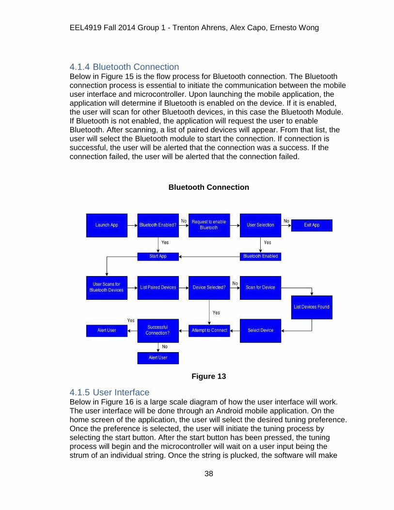
EEL4919 Fall 2014 Group 1 - Trenton Ahrens, Alex Capo, Ernesto Wong
38
4.1.4 Bluetooth Connection Below in Figure 15 is the flow process for Bluetooth connection. The Bluetooth connection process is essential to initiate the communication between the mobile user interface and microcontroller. Upon launching the mobile application, the application will determine if Bluetooth is enabled on the device. If it is enabled, the user will scan for other Bluetooth devices, in this case the Bluetooth Module. If Bluetooth is not enabled, the application will request the user to enable Bluetooth. After scanning, a list of paired devices will appear. From that list, the user will select the Bluetooth module to start the connection. If connection is successful, the user will be alerted that the connection was a success. If the connection failed, the user will be alerted that the connection failed.
Bluetooth Connection
Figure 13
4.1.5 User Interface Below in Figure 16 is a large scale diagram of how the user interface will work. The user interface will be done through an Android mobile application. On the home screen of the application, the user will select the desired tuning preference. Once the preference is selected, the user will initiate the tuning process by selecting the start button. After the start button has been pressed, the tuning process will begin and the microcontroller will wait on a user input being the strum of an individual string. Once the string is plucked, the software will make
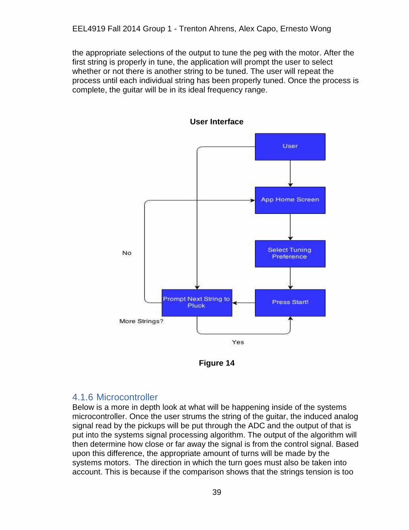
EEL4919 Fall 2014 Group 1 - Trenton Ahrens, Alex Capo, Ernesto Wong
39
the appropriate selections of the output to tune the peg with the motor. After the first string is properly in tune, the application will prompt the user to select whether or not there is another string to be tuned. The user will repeat the process until each individual string has been properly tuned. Once the process is complete, the guitar will be in its ideal frequency range.
User Interface
Figure 14
4.1.6 Microcontroller Below is a more in depth look at what will be happening inside of the systems microcontroller. Once the user strums the string of the guitar, the induced analog signal read by the pickups will be put through the ADC and the output of that is put into the systems signal processing algorithm. The output of the algorithm will then determine how close or far away the signal is from the control signal. Based upon this difference, the appropriate amount of turns will be made by the systems motors. The direction in which the turn goes must also be taken into account. This is because if the comparison shows that the strings tension is too

EEL4919 Fall 2014 Group 1 - Trenton Ahrens, Alex Capo, Ernesto Wong
40
tight, the motor must turn one way. Whereas if the comparison shows that the string is too loose, it must turn in the opposite direction. The direction in which the motor turns will be determined by the H-Bridge.
Microcontroller
Figure 15
4.1.7 Tuning Mechanism (Electrical) Below is the electrical side of how the motors are being controlled. The motors direction will be determined by the H-bridge. The direction in which the H-bridge will turn the motors will be determined by the microcontrollers signal processing algorithm. The amount in which the peg will be turned is to be determined by the systems encoder.
Tuning Mechanism (Electrical)

EEL4919 Fall 2014 Group 1 - Trenton Ahrens, Alex Capo, Ernesto Wong
41
Figure 16
4.1.8 Tuning Mechanism (Mechanical) Below is the mechanical side of the system‟s tuning mechanism. The motor's mechanical input will be determined by the system‟s microcontroller tuning algorithm. The input signal will begin the turning of the gear in the motor. Once the motor begins to turn the gear shaft will turn the peg that is attached to the worm gear. The turn in the worm gear will then modify the string's tension. The peg will also be accessible to manual tuning by the user.
Tuning Mechanism (Mechanical)

EEL4919 Fall 2014 Group 1 - Trenton Ahrens, Alex Capo, Ernesto Wong
42
Figure 17
4.2 Hardware The following sections will discuss the hardware design and the different options that were available to consideration. The team is operating on a limited budget and therefore will look for cost friendly components and techniques when choosing and assembling all components.
4.2.1 Pickups The team will be using quadraphonic pickups for this project as it allows for each individual string to be analyzed separately more easily than some other type of pickup. As there are few hexaphonic pickups for sale, and even less quadraphonic pickups, there are not many places to purchase from. One place to purchase quadraphonic pickups from is Ubertar. They have a quadraphonic pickup for sale, but at $135 other options will have to be considered. Another option is the Roland GK-3. This pickup contains six polyphonic pickups contained in a plastic housing. The GK-3 is priced at $170 so it is not going to be a feasible option. Also the coils are very small and contained in a special housing. Tearing down the GK-3 would be very difficult, as would remounting the pickups under the four bass guitar strings. The pickups that will be chosen are the hexaphonic pickups from the Power Gig Guitar. The guitar can be easily obtained from Amazon or EBay for around $50. The guitar will simply be torn down and the pickups will be removed to use in the

EEL4919 Fall 2014 Group 1 - Trenton Ahrens, Alex Capo, Ernesto Wong
43
project. They individual pickups can easily be removed from the PCB so that they can be aligned with the four strings of the bass guitar.
4.2.2 Motor Design The motors selected must be capable of turning the thickest string of the guitar (E string) at its highest frequency (highest tension). The following subsections will outline the design process the team went with when coming to a final decision on the motor to be used.
4.2.2.1 Requirements The requirements needed by the systems motors was something that the team put a large amount of thought into. The motor control will be handled by the microcontroller, and the direction by the H-Bridge, which amount of turn will be determined by the signal recognized through the pickups. Once the user makes the desired note selection through the user interface, the signal induced on the pickups will be compared to the desired signal. Based upon the difference in frequency between the two signals, the tuning motors will begin to rotate accordingly.
In order for this to work, the motors must be able to supply a sufficient amount of torque. Calculations are shown below that consider the torque required by the motor for the highest torque required scenario (the thickest string at its highest tension). The torque needed by the motor was not the only parameter considered, but the size of the motor played an even more important role. The size of the motor needs to be able to fit on the head of the guitar so that it can be properly mounted to the tuning gear. With the geometry of the bass guitar used having four strings, with two on either side of the head, the amount of space available for the motors is limited. In addition, the current draw was another important factor in the motor design.
The team estimated a maximum of 1000 mA currents draw from the motors in order to get minimal power consumption. This estimation was based upon the calculated torque values provided. Finally the team must consider low cost as the most important factor. With a limited budget and the need for four motors, the team must examine feasible options in terms of motor cost.
4.2.2.2 Tension Calculations There is an equation available to use in order to determine the tension at which your string will vibrate. You need three pieces of information which are the Unit Weight (UW), the Scale Length (L), and the Frequency (F) of the string. The equation is show below[7].
𝑇 =(𝑈𝑊 ∗ (2 ∗ 𝐿 ∗ 𝐹)2)
386.4
EEL4919 Fall 2014 Group 1 - Trenton Ahrens, Alex Capo, Ernesto Wong
44
The unit weight (UW) of the string is expressed in pounds per linear inch (lb/in), the scale length (L) is measured in inches (in), and the frequency (F) is measured in hertz (Hz). The bass guitar used has a scale length of 34 inches which is the standard length for a bass guitar. Its unit weight was undetermined due to the team being unsure of the exact strings used, so an estimated value of 0.00053791 was used based upon information found on the web.
The frequency for the E string is 41.2 Hz. With these being the standard used to determine the maximum tension needed to be overcome, a value of 10.9 lbs must be considered. With the exact string composition being unsure, the team decided to do additional research to find a reasonable torque gauge that the bass guitar string must overcome. It was found through research that no string shall be tuned passed 40-45 lbs-in for regular playing. It was also found that the smaller gauge strings break when reaching 60 lb-in of torque, and the larger gauge strings being anywhere from 90-150 lb-in of torque. Obviously the goal is not to break the string of the guitar, therefore the team's motor need in terms of torque should be able to apply up to 30-40 lb-in of torque[8].
4.2.2.3 NEMA 17 Stepper Motor The NEMA 17 stepper motor was the first motor the team came across during the selection process. There was a lot of five motors sold in a bundle for $39.99 on eBay. This amount and price was very appealing the team for a couple of reasons. One reason being the number of motors needed by the project was only four, with five motors the team had the option to see what one motor alone is capable of through stress testing. The motors were 1.7" by 1.7" which meets the size needed by the head of the bass guitar. It draws up to 1.2 A meaning a low power consumption. It also had the option of 1.8° or 0.9° per step, with either 200 or 400 steps. This was another very attractive feature to the team because it allows the pegs to be tuned very precisely. The only downfall to this motor was the torque output. The NEMA 17 was only capable of delivering up to 62 oz-in of torque which corresponds to about 3.9 lb-in of torque, thus the team ruled it out of consideration.
4.2.2.4 NEMA 24 Stepper Motor The NEMA 24 stepper motor was the second option considered by the team. It is the same manufacturer as the NEMA 17, with the difference being the amount of torque it can provide. It also provides a low noise/low vibration which is desired by the team. It has a 567 oz-in torque capability which translates to about 35.4 lb-in of torque and meets the teams requirements in that respect. The two main downsides to this particular motor is the price and current draw. For a single motor, the cost is $71.99 on eBay and its current draw is up to 4 A. With only a $200.00 budget and a desired 1 A current draw, the team decided to rule this motor out as well.

EEL4919 Fall 2014 Group 1 - Trenton Ahrens, Alex Capo, Ernesto Wong
45
4.2.2.5 Pololu 1501MG Servo Motor The Pololu 1501MG servo motor was examined by the team. It requires only 6 volts to power and is an attractive component in terms of size and price. The 1501MG costs $19.95 per motor and has a light weight of only 60 grams. The downside for this motor again was the torque output only being able to deliver 240 oz-in of torque which translates to 15 lb-in of torque. With the cost of the motors considered already being quite high and with minimal torque output being displayed, the team must begin to consider other options in order to turn the pegs with enough torque, and still be a reasonable price.
4.2.3 ROB-12472 The ROB-12472 Standard Gear motor was the most appealing find in terms of motors for the project and seemed to checkout in all requirements also. Its operating range has a range from 3-12 V which gave the team options in terms of power for the motor. It also has a stall current of 0.5 A (at 12 V) which falls under the 1 A current draw limit. The ROB-12472 is also capable of supplying up to 613 oz-in of torque which is approximately 38 lb-in and is the first motor to meet the minimum torque requirements. The price for this motor was only $19.95 and the size of it also met project specifications.
4.2.4 Black & Decker Li2000 The Black & Decker Li2000 power screwdriver was another option considered by the team. A power screwdriver is essentially the same thing as a DC gear motor and could be another reasonable option for the team in terms of motors. The Li2000 is capable of supplying up to 40 lb-in of torque and can be modified to fit the around on the tuning peg. Its low price of $19.99 was another appealing factor. One main reason the team considered this is because it comes with it own rechargeable lithium ion battery, which would negate the need to power the screwdrivers from the PCB's power source. It is available at the nearest hardware store and could prove to be a good choice for the team.
Motor Comparison Table
Motor
RequiredTorque
Continuous
Rotation
Cost
Friendly
H-Bridge
Compatibility
In
stock
NEMA17 No Yes Yes Yes Yes
NEMA 24 No Yes No Yes Yes
Pololu 1501MG
No Yes Yes Yes Yes
ROB-12472
Yes Yes Yes Yes Yes
Table 6

EEL4919 Fall 2014 Group 1 - Trenton Ahrens, Alex Capo, Ernesto Wong
46
4.2.5 Decision With a limited budget and time becoming a factor, the team decided to go with the ROB-12472 Standard Gearmotor for the projects tuning motors. The motors are affordable given that they are the most expensive piece of the project. They meet all of the requirements the project calls for with the exception of the desired tuning time. The ROB-12472 motor is only capable of a maximum 6 rpm meaning that it would take 10 seconds to do a full rotation. With the amount of more capable motors being out of the given price range, and the general expectation that most users instruments will not be too far out of tune from the next desired setting, the team thought this was a necessary sacrifice. Below are figures of the ROB-12472 Standard Gearmotor used in the project[9].
ROB-12472 Dimensions
Figure 18
4.2.6 H-Bridge Design The design needs H-Bridge circuits in order to allow the DC motor operate in a bi-directional manner, be controlled through software, and also be able to stop at an instants notice. The following will outline the different components considered during the H-Bridge design process.
4.2.6.1 Bipolar Junction Transistor (BJT) A lot of H-Bridge circuits use BJTs to control motor direction. The BJT acts as a current controlled switch, where the base of the component requires a minute amount of current in order to let the collector and emitter pass a much higher current. BJT's are solid state devices and thus have very fast switching time and operate with minimal noise. A standard 0.7 voltage drop is realized across the base and emitter nodes. This drop paired with the amount of current the device is passing is able to control the power dissipation of the device. BJTs are capable
EEL4919 Fall 2014 Group 1 - Trenton Ahrens, Alex Capo, Ernesto Wong
47
of digital signal controlling and can handle different current characteristics and thus are a viable component to be considered for the H-Bridge design.
4.2.6.2 Field Effect Transistor (FET) Like BJTs, FETs are another example of common components used in H-Bridge design. They are solid state like the BJT yielding a low noise output, the main difference being they are voltage controlled devices in contrast to current controlled. When an appropriate amount of voltage is applied to the gate, current is allowed to pass through both the source and gate terminals. Unlike the BJT, FETs do not exhibit a voltage drop across the junctions. The analogous effect to the voltage drop in the BJT for the FET would be the internal resistance seen that dictates the maximum current the device is able to allow, along with the power dissipation. FETs also are capable of handling digital signal control and high current, and because of these were considered by the team.
4.2.6.3 Electromechanical Relay (EMR) An electromechanical relay H-Bridge circuit uses mechanical switches that are controlled by a magnetic force. Like the BJT, a small voltage drop is realized across the EMR. EMRs are also capable of passing high current for required applications. The main downfall to these relays is the mechanical switching components, which can be loud, bulky, and have a slow performance in terms of switching time. The team will likely not choose an EMR component in order to design the systems H-Bridge.
4.2.6.4 Solid State Relay (SSR) Solid state relays work very similarly to electromechanical relays with the exception of utilizing mechanical components. Since these relays are solid state, they tend to be more reliable and perform faster than the aforementioned electromechanical relay. One negative feature that stuck out to the team was the size of these components in respect to the needs of the project. A higher amount of current requires a larger relay and this requirement results in a price that is out of the teams budget range.
4.2.6.5 Texas Instruments L293 Dual H-Bridge The team began to veer away from manually assembling an H-Bridge when schematics were investigated. The complexity of the schematics would leave much too large of a footprint on the overall system, therefore integrated H-Bridge circuits were investigated instead. The first find was the TI L293 dual H-Bridge. It has a very wide voltage range from 4.5-36 VDC and has a low cost of only $3.75. The biggest benefit was that one single IC had two H-Bridge circuits built in, meaning the purchase of only two ICs would be necessary.
4.2.6.6 Decision After comparing the different options the team decided to go with the IC approach in terms of H-Bridge design. With two ICs only costing a total of $7.50 the team thought this was the best option because the budget supplied was beginning to slowly diminish. These ICs are also capable of taking in PWM signals for speed and rotational controls which was a requirement for the motors

EEL4919 Fall 2014 Group 1 - Trenton Ahrens, Alex Capo, Ernesto Wong
48
in order to output prime tuning performance. Below in Figure 22 is a picture of the L293 dual H-bridge[10].
L293DNE Pins
Figure 19
4.2.7 Encoder Design In order for the system to know how many turns that the motors have made an encoder must be included. Time based tuning algorithms prove to be an unsatisfactory method of approach due to the tension in the string and the battery charge playing a role in the speed in which the motors may turn. To negate that problem the team decided to implement a turn based algorithm that would enable to motors to make fractions of turns. Through trial and error the team was able to recognize about a 16 Hz change per full turn on the tuning pegs, which equates to 4 Hz change per quarter turn. Rotary encoders are capable of keeping track of turns and are able to command the motors to make a certain amount of turns as well. Several different rotary encoders were examined before selecting one that the team will purchase.
4.2.7.1 Photoresistor A photoresistor works by changing its resistance based upon the amount of light that it is receiving. This type of encoder could work by facing the output of the encoder toward an LED. In order for the encoder to be able to see if it is receiving light from the LED, a small disk that rotates could be mounted in between the output of the encoder and the LED itself. There could be two holes on the disk that allow light to pass, and two covered spots on the disk that would not allow light to pass. This would allow for quarter turns to take place by the

EEL4919 Fall 2014 Group 1 - Trenton Ahrens, Alex Capo, Ernesto Wong
49
encoder reading HIGH when it is receiving light from the LED and LOW when no light is being read. This process could be easily implemented as the parts required are cheap and readily available, but it has been found that the response time of these encoders can prove to be inadequate for some applications.
4.2.7.2 Photodiode A photodiode works similarly to the functionality of the photoresister. The difference is that instead of reading light as a resistance, the sensor converts that light into current. The same method of approach would be used as the photoresister with the rotating disk with alternating holes. The parts for this process are easily accessible and could be easily implemented on the Automatic Guitar Tuner.
4.2.7.3 Reflective Sensor A reflective sensor works by using an infrared LED and phototransistor to measure the amount of reflectance an object is emitting to the sensor. In order for this to work, the object must be only about an eighth of an inch away from the sensor. The object for the projects applications again would be a disk, but instead of having holes would have different colors. In order for the encoder to read HIGH, the output sensor must see a dark color, and for the encoder to read LOW, it must sense a highly reflective color. This is an option that the team will take into deep consideration in that it would be very simple to implement, and would not require the cutting of holes into the rotating disk. The disk would only have to change color from white to black, which could be done by filling in portions of the disk with marker.
4.2.7.4 Synchro The synchro encoder uses a conductive collar, an insulator and a signal wire. The collar would be fitted around the axle of the tuning peg in the case of the Automatic Guitar Tuner. The insulator would be applied to the surface of the collar in an alternating fashion. The conductive collar would then charge and the signal wire would contact the surface of the collar where it will contact the conductive surface of the collar and the insulator in an alternating fashion. This means that when the signal wire contacts the insulator, the encoder reads LOW, whereas when signal wire contacts the collar the encoder reads HIGH. Implementing this technique would be difficult because of the geometry of the project and will likely be ruled on in terms of the decision on which encoder is to be used.
4.2.7.5 Reed Switch The Reed Switch encoder works similarly to that of the reflective sensor, the difference being instead of reading a reflection, this encoder reads if there is a magnet being seen by the output. If the output sensor reads that there is a magnet in front if it, the switch would activate and read HIGH, in contrast if there is not a magnet in front of the sensor, a LOW would be read. The Reed Switch would be a good fit for the design but works based upon the amount of magnet

EEL4919 Fall 2014 Group 1 - Trenton Ahrens, Alex Capo, Ernesto Wong
50
strength, meaning that the results would be variable. If the magnets were not of sufficient strength, the Reed Switch may not read a HIGH at all.
4.2.7.6 Decision After much research was put in by the team, it was decided that implementing the reflective sensor encoder option would be the best option. The reason that this encoder was the best option is that the mounting of it only required the disk and the encoder alone. It does not require an additional LED or magnet to take readings from. It also would not result in cutting out holes in the disk, which could prove to be an ineffective approach because the size of the disk will already be small. There also is no resistive discharge time that a resistance reading component would have to go through, meaning that the response time of the reflective sensor would provide the best results.
4.2.7.7 Pololu QTR-1RC Reflective Sensor The QTR-1RC is a reflective sensor made by Pololu. It is a tiny component that has dimensions of 0.5" by 0.3" and can be bought in packs of two for only $4.25. This meets the systems requirements in both terms of footprint size and cost effectiveness. It is equipped with a single infrared LED and phototransistor pair. The sensor will be mounted on the head of the guitar in front of an alternating color rotating disk. Below in Figure 24 is a picture of the QTR-1RC reflective sensor.
4.2.8 Microcontroller Before designing a microcontroller, the chip being used must be selected. There are many microcontrollers already made like Arduino and the MSP 430. They already have a microprocessor on them and sometimes other features. This is a great way to test different brands of microprocessors to see which will fit best for the project. A microcontroller always has a datasheet where its functionality is described. In the datasheet, there is usually a reference schematic design for the microcontroller. This makes it easy to get a microcontroller board designed and built. When designing the microcontroller, power supply regulation is very important. Most microcontrollers run at either 5v or 3.3v. There are two main types of DC-DC power regulation, linear and switching. Linear is simple, but switching is more efficient. Linear involves one device, usually a three pin IC and some capacitors, whereas switching will require a larger IC and various other components. Usually at least three power supply caps: ~10uF Aluminum across the unregulated supply, ~4.7uF across the regulated supply, and 0.1uF ceramic across the power rails of the microcontroller. If there is not one elsewhere in the circuit there should be a ~300uF aluminum cap across the unregulated power too. A power indication LED is not necessary, but makes it easy to tell if the board has power. A LED in series with a 1K ohm resistor, running off the regulated is one method. Most microcontrollers have some sort of reset or clear pin that, when bought to a certain state, resets the microcontroller and makes it start its program again.

EEL4919 Fall 2014 Group 1 - Trenton Ahrens, Alex Capo, Ernesto Wong
51
Usually the pin should be held at a high state enabling the microcontroller to operate and a reset switch can be added that momentarily brings it to low, thus resetting the microcontroller. Some microcontrollers have built in pull up resistors, so that all is required is adding a switch to ground. The programming header is where the microcontroller connects to a computer to receive its program. Different chips have different number of pinned headers. The datasheet will tell what the pins are and where to connect to the header. Sometimes there can be problems with adjacent data or clock lines, and sometimes it is recommend adding an R/C filter on one or both of the lines. This can help reduce crosstalk and interference, resulting in less problems later on. Not all microcontrollers have an internal oscillator. An oscillator somewhere is required to give the microprocessor a synchronized clock for all of its sub-systems. Even if it does, sometimes a particularly high or low operating frequency, or a more accurate clock for intense timing applications may be necessary. These can take various forms. An R/C Oscillator is cheap and inaccurate. A crystal oscillator is more accurate. They will require a couple of small capacitors to function. A canned oscillatoris essentially a crystal oscillator and the capacitors in a little box or container. Port headers are simply male or female headers connected to relevant pins. Terminal blocks can also be used for more heavy-duty use. Most microcontrollers will not need pull up or pull down resistors, but can be added to 'default' the pins to high or low. 47K-67K ohms, to +V or GND are often used. Other times some extra circuitry between the MCU and the external connections may be required for certain applications. For an application involving motors extra circuitry is required to drive the motors. A H-bridge is usually used to allow voltage to be applied to the motor in either direction. For certain motors the can allow not only operation in both directions, but also braking, free running, and shoot-through. A separate H-bridge is required for each of the motors. In the case of this project, that will be four. One thing to consider when powering the motors is noise and interference. Since the motors will likely be powered by the same power supply as the rest of the circuit, it is important to design for this. It is important to design the motor drivers so that they do not generate noise to interfere with the microcontroller, and do not cause large current or voltage spikes that could damage or destroy the microcontroller. A 442X MOSFET driver can be used to combat these problems. This is used to drive the MOSFET's controlled by a low current 5 volt signal from the microcontroller. EMF protection diodes and capacitors of different sizes can be used to support the circuit‟s power requirements. This often includes a 47uF Electrolytic Capacitor and a 20uF Tantalum capacitor in parallel across the power rails, and a 0.1uF ceramic/ capacitor across the power rails of every IC.

EEL4919 Fall 2014 Group 1 - Trenton Ahrens, Alex Capo, Ernesto Wong
52
4427 MOSFET Driver
Figure 20
The team is considering using the Atmega32. Using the Atmega32 would make the PCB design easier. The Atmega32 is not a surface mount chip so a socket could be used. The IC socket is used for a not fixed connection of a microcontroller with a target system, so that it can be changed anytime or to be plugged in a programming interface. This would allow the microcontroller to easily be swapped out in case it was damaged. The following figure is the pin layout of the Atmega32.
Figure 21

EEL4919 Fall 2014 Group 1 - Trenton Ahrens, Alex Capo, Ernesto Wong
53
Another option for the microcontroller that is being considered in this project is using the Texas Instruments MSP430F5529 processor. The team is already in possession of a Launchpad board that features this microcontroller. This will assist in the design and testing of the project. This chip is a quad flat pack (QFP) chip so the chip will not be able to easily swap out the chip like the Atmega32. The chip must be carefully soldered onto the PCB. Using a soldering iron will be the most likely method of mounting. Using solder paste and a hot air rework station is another option that is sometimes used for soldering smaller components. It uses hot air to melt the solder paste so the chip is not at risk of being damaged by a hot iron. The following figure is the pin layout of the MSP430F5529.
MSP430 Pins
Figure 22
After considering multiple microcontrollers, the team had decided to go with the MSP430F5529 due to its higher ADC resolution, and the team is familiar with the
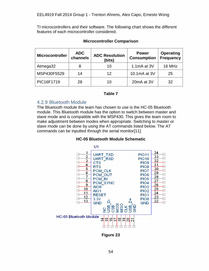
EEL4919 Fall 2014 Group 1 - Trenton Ahrens, Alex Capo, Ernesto Wong
54
TI microcontrollers and their software. The following chart shows the different features of each microcontroller considered.
Microcontroller Comparison
Microcontroller ADC
channels
ADC Resolution
(bits)
Power Consumption
Operating Frequency
Atmega32 8 10 1.1mA at 3V 16 MHz
MSP430F5529 14 12 10.1mA at 3V 25
PIC16F1719 28 10 20mA at 3V 32
Table 7
4.2.9 Bluetooth Module The Bluetooth module the team has chosen to use is the HC-05 Bluetooth module. This Bluetooth module has the option to switch between master and slave mode and is compatible with the MSP430. This gives the team room to make adjustment between modes when appropriate. Switching to master or slave mode can be done by using the AT commands listed below. The AT commands can be inputted through the serial monitor[11].
HC-05 Bluetooth Module Schematic
Figure 23

EEL4919 Fall 2014 Group 1 - Trenton Ahrens, Alex Capo, Ernesto Wong
55
Main Pin Assignments For HC-05
Pin Name Description
1 TXD Data transmission line (UART Data output)
2 RXD Data transmission line (UART Data input)
11 Reset Connect to low for reset
12 3.3V VCC (Voltage supply for logic)
13 GND Ground
31 Module Status
1 Hz Flashing LED = for power on at command mode
2 Hz fast flashing = Pairing mode
2 Hz slow flashing = communication mode
32 Pairing Status Output low TTL before pairing, and vice versa
34 Mode
Selection High TTL for AT commands mode
Low TTL for pairing and communication mode
Table 8
Common AT Command List For HC-05
Command Description
AT+ROLE = 0 Set to Slave mode
AT+ROLE = 1 Set to Master mode
AT+CMODE = 1 Set memory mode; allow any address
for connecting
AT+CMODE = 0 Set memory mode; only allow certain
address for connecting
AT+PSWD = xxxx Set pairing password
AT+UART= <Param>, <Param2>, <Param3>, ( i.e. AT+UART=9600, 0, 0)
Refer to BT0305 module AT command list
AT+NAME = xxxx Set Bluetooth name
Table 9

EEL4919 Fall 2014 Group 1 - Trenton Ahrens, Alex Capo, Ernesto Wong
56
4.2.10 PCB Virtually every electronic product is constructed with one or more printed-circuit boards (PCB's). The PCBs hold the ICs and other components and implement the connections between them. PCBs are created in abundance for portable electronics, computers, and entertainment equipment. Using a PCB is a requirement for this project and must be carefully designed.
The PCB for this project will be designed using EAGLE Light Edition. The only limitations of the Light version of EAGLE PCB Design Software is that the useableboard area is 4 x 3.2 inches, and the board can only have two signal layers (top and bottom). There is a lot that needs to be included when designing a PCB. The PCB‟s documents should include hardware dimensional drawings, schematic, BOM, layout file, component placement file, assembly drawings and instructions, and Gerber file set. User guides are not required but can be helpful. The Gerber file set is PCB terminology for the output files of the layout that are used by many PCB manufacturers to create the printed circuit board. A complete set of Gerber files includes the following:
Silkscreen top and bottom
Solder mask top and bottom
All metal layers
Paste mask top and bottom
Component map (X-Y coordinates)
Assembly drawing top and bottom
Drill file
Drill legend
FAB outline (dimensions, special features)
Netlist file The special features included in the FAB outline normally include notches, cutouts, bevels, back-filled vias-in-pad (used for BGA-type IC packages that have an array of pins under the device), blind or buried vias, surface finish and leveling, hole tolerances, layer count, and more. The schematic is an important part of designing a printed circuit board. Schematics control the project, so accuracy and completeness are crucial for success. They include information that is necessary for the proper operation of the circuit. A schematic should include adequate design details, such as pin numbers, names, component values, and component ratings. Embedded within each schematic for each component is the manufacturer part number used to determine price and specifications. The package specification determines the size of the footprint for each component. The first step when placing components should be to make sure the exposed copper for each part is in the proper location and is made slightly larger than the component pins (3 to 20 mils) depending on available board area and soldering method to be used.
EEL4919 Fall 2014 Group 1 - Trenton Ahrens, Alex Capo, Ernesto Wong
57
Component placement is the next step in the process of designing a PCB. Component placement is determined based on thermal management, function, and electrical noise considerations. A first-pass component placement step commences after an outline of components has been made and interconnect position have been assigned. Immediately after the individual components are placed, they should be reviewed so that adjustments can be made to make routing easier and optimize performance. Placement and package sizes are often reconsidered and changes are made at this point based on size and cost. Components that consume more than 10 mW of power or more than 10 mA of current are usually considered to be powerful enough for additional thermal and electrical considerations. Sensitive signals should be shielded from noise sources with planes and be kept impedance-controlled. Power management components, such as voltage regulators, should utilize ground planes or power planes for heat flow to remove heat from the component quickly and efficiently. Layer transitions for high current paths should be made with two to four vias at each layer transition. Multiple vias should be placed at layer transitions to increase reliability, reduce resistive and inductive losses, and improve overall thermal conductivity. The heat generated by the IC is transferred from the device to the copper layers of the PCB. The ideal thermal design is to have the entire board at the same temperature. The copper thickness, number of layers, continuity of thermal paths, and board area will have a direct impact on the operating temperature of components. To easily reduce operating temperatures of components, more layers of solid ground or power planes should be used that are connected directly to heat sources with multiple vias. Establishing effective heat and high-current routes will optimize the heat transfer by means of convection. The use of thermally conductive planes to spread the heat evenly can dramatically lower the temperature by maximizing the area used for heat transfer to the atmosphere. For even heat distribution, the following formula should be used to estimate surface temperatures:
𝑃 = (𝐻𝑒𝑎𝑡𝐶𝑜𝑛𝑣𝑒𝑐𝑡𝑖𝑜𝑛 ) 𝑥 𝐴𝑟𝑒𝑎 𝑥 (𝛥𝑇) Where: - P is power dissipated on the board, area is simply board area, - ΔT is surface temperature – ambient temperature, and - HeatConvection is the convection constant based on ambient conditions. When placing components, they should be placed in the following order: connectors, power circuits, sensitive and precision circuits, critical circuit components, and then the rest. The schematic is built around each part on the PCB and completely interconnected. Routing priority for the circuit is chosen

EEL4919 Fall 2014 Group 1 - Trenton Ahrens, Alex Capo, Ernesto Wong
58
based on power levels, noise susceptibility, or generation and routing capability. In general, trace widths of 10 to 20 mils are used for traces carrying 10 to 20 mA and 5 to 8 mils for traces carrying less current than 10 mA. High-frequency (greater than 3 MHz) and rapidly changing signals should be carefully considered when routed along with high-impedance nodes. The final layout should be reviewed so that physical locations and routing paths can be adjusted iteratively until the circuit is optimized for all design constraints. The number of layers depends on power levels and complexity. Add layers in pairs since the copper cladding is produced in pairs, usually of two or four layers. The routing of power signals and planes, the grounding scheme, and the board‟s ability to be used as intended all influence operation. Final inspections should involve verification that sensitive nodes and circuits are properly shielded from noise sources, solder mask exists between pins and vias, and the silkscreen is clear and concise. When determining layer stack-up, use the first inner layer below the component sides as ground and assign power planes to other layers. Stack-ups are created in a manner that balances the board relative to the midpoint of the Z axis. Design Rule Checking or DRC is the area of Electronic Design Automation that determines whether the physical layout of a particular chip layout satisfies a series of recommended parameters called Design Rules. The DRC can only catch errors that it has been programmed to monitor, and DRC rule sets often change based on individual designs. At the minimum, the design rule checking should cover package-to-package spacing, unconnected nets (a unique name identifying each node of the circuit), shorted nets, air-gap violations, if vias are too close to solder pads, if vias are too close to each other, and vertical clearance violations. Many other important DRC rules can be set to ensure a robust design. For example, clearances should be kept at or above 5 mils. Vias should not be located within surface-mount pads (unless back-filled). And, solder mask should be between all solder points. Cost is often a driving influence behind PCB design, so it is good to understand the cost adders in PCB manufacturing. A typical board is two to four layers, with no drill holes less than 10 mils in diameter and 5-mil minimum air gaps and trace widths. It also should be 0.062 in. thick with standard FR-4 and a copper foil weight of 1 oz. Additional layers, extra thick or thin boards, vias-in-pad, back-filled vias (non-conductive preferred due to conductivity limitations and thermal expansion differences), blind/buried vias, and lead time all substantially add to the overall cost. Manufacturer capabilities should be understood when the PCB design commences. PCB fabs are routinely contacted about capabilities and cost reduction techniques when designing PCBs for manufacturability.
The final PCB was designed using Eagle Cad and printed by OSH Park. Below is the design schematic and the board layout.

EEL4919 Fall 2014 Group 1 - Trenton Ahrens, Alex Capo, Ernesto Wong
59
Board Schematic
Figure 24
Board Layout

EEL4919 Fall 2014 Group 1 - Trenton Ahrens, Alex Capo, Ernesto Wong
60
Figure 25
4.2.11 Mobile Device The mobile device being used for the user interface will be a Samsung Galaxy S4. This mobile device will serve as the first device used for testing the mobile application. This device includes Bluetooth capabilities, which is required in order for the Automatic Guitar Tuner to work properly. Once the mobile application is ready and fully functional, the application can be downloaded onto any Android mobile device.
4.3 Software Aside from the hardware, the software is the backbone of this project. The project requires the software in order to perform the tuning process in a quick, accurate, and efficient manner.
4.3.1 Mobile Application The user interface is done through a mobile application on an Android smartphone. The team decided to use Android OS due to its open source nature as opposed to Apple iOS. Also each member has an Android smartphone, which the team found convenient. It would be complete nonsense to use funds for a device that the team already has.
The user interface will be an application on an Android smartphone that will communicate to the microcontroller wirelessly through Bluetooth technology. This feature will allow the user to easily set the tuning preferences on an everyday device. It will also allow the user to access the controls within a close proximity to the Automatic Guitar Tuner. At first the user will have to establish a Bluetooth connection with the Android smartphone and the Bluetooth module on the microcontroller. Once the devices are connected, piconet will be created so the two devices can automatically connect to each other once they are within close radio proximity as long as Bluetooth in both devices are enabled.
On the Android smartphone, the user can go into Settings → Bluetooth to enable Bluetooth or select the Bluetooth button on the home screen. From there, the user can search and select for the Bluetooth module on the microcontroller if it is in close proximity. Once this is done, the application will be able to use the Bluetooth function properly.
The GUI (Graphic User Interface) for the application is designed for easy use and navigation. The first screen will welcome the user to the application and will prompt the user to select one of the five pre-set tuning preferences. Through a drop down menu, the user will select a tuning preference. Once chosen, the selected tuning preference will display. The screen will then prompt the user to press the Start to initiate the tuning process. The user will then be prompted to pluck the first string (the E string). Once plucked the system will input the vibrations of the string and process the signal. The output will then signal the

EEL4919 Fall 2014 Group 1 - Trenton Ahrens, Alex Capo, Ernesto Wong
61
motors to adjust the strings tension to match the correct tuning frequency. When the automated tuning process is finished with all 4 strings, the screen will return back to the home screen and prompt to select a tuning preference. A button to exit will also be available on the home screen to allow the user to exit the application. Below are examples of the desired layout of the GUI for the application.
Home Screen Design
Figure 26
Process Screen Design

EEL4919 Fall 2014 Group 1 - Trenton Ahrens, Alex Capo, Ernesto Wong
62
Figure 27
Process Complete Screen Design
Figure 28
4.3.2 Signal Processing Algorithm The Automatic Guitar Tuner has to be able to quickly and efficiently analyze the frequency of each individual string when it is plucked by the user. The speed and the quality of this information is based heavily on the type of frequency analysis technique chosen, in this case using Fast Fourier Transform (FFT). The Fast Fourier Transform is the most common and efficient way of processing musical signals in general.
The FFT algorithm will be used on the sample of data collected by the pickups from the analog input of the MSP430. The algorithm will have to analyze these samples fast enough so that it can send signals to the motors on how much to turnwhile simultaneously updating that information based on feedback from the algorithm. This system will function by repeating the process for each the four strings on the bass guitar.
From the receiving signal samples, the algorithm must continuously compare it to the proper tuning frequency selected by the user on the user interface. First the team will have to input the frequencies of all 5 tuning presets by manually tuning the bass guitar to each tuning preset and record the proper frequencies. The signal samples will then be saved and stored on the MSP430.
In order to tune the guitar in less than 30 seconds with accuracy specified in the objectives, the system will have to implement the FFT algorithm in excess of
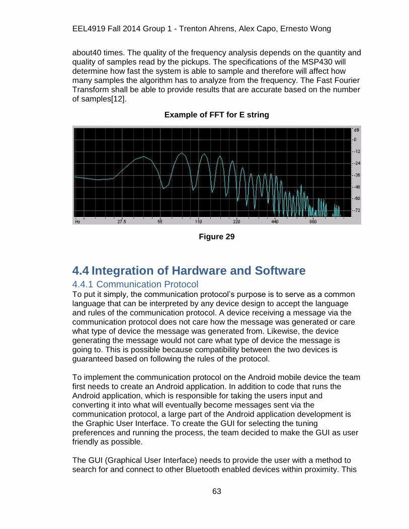
EEL4919 Fall 2014 Group 1 - Trenton Ahrens, Alex Capo, Ernesto Wong
63
about40 times. The quality of the frequency analysis depends on the quantity and quality of samples read by the pickups. The specifications of the MSP430 will determine how fast the system is able to sample and therefore will affect how many samples the algorithm has to analyze from the frequency. The Fast Fourier Transform shall be able to provide results that are accurate based on the number of samples[12].
Example of FFT for E string
Figure 29
4.4 Integration of Hardware and Software 4.4.1 Communication Protocol To put it simply, the communication protocol‟s purpose is to serve as a common language that can be interpreted by any device design to accept the language and rules of the communication protocol. A device receiving a message via the communication protocol does not care how the message was generated or care what type of device the message was generated from. Likewise, the device generating the message would not care what type of device the message is going to. This is possible because compatibility between the two devices is guaranteed based on following the rules of the protocol. To implement the communication protocol on the Android mobile device the team first needs to create an Android application. In addition to code that runs the Android application, which is responsible for taking the users input and converting it into what will eventually become messages sent via the communication protocol, a large part of the Android application development is the Graphic User Interface. To create the GUI for selecting the tuning preferences and running the process, the team decided to make the GUI as user friendly as possible. The GUI (Graphical User Interface) needs to provide the user with a method to search for and connect to other Bluetooth enabled devices within proximity. This

EEL4919 Fall 2014 Group 1 - Trenton Ahrens, Alex Capo, Ernesto Wong
64
will be implemented utilizing the device settings menu, which is found on all android devices. Upon selecting the device settings menu, the user is presented with the option to search for and connect to remote Bluetooth devices. After which the user is presented with the names and MAC addresses of devices found within proximity. The user sees when interacting with the Android application.
In addition to the Graphic User Interface, the control logic written in Java for the Android application has an even larger role in this project. This is where all of the activity takes place to interpret the user‟s input, support the Graphic User Interface, manage the Bluetooth connection and data transmissions, and implement checks if the process is complete. The application checks to see that Bluetooth is enabled on the mobile device, requesting user input when prompt ,and allow the user to exit the application and therefore terminate the process. Although it is possible to write an application that will enable Bluetooth communication on its own without notifying or requesting permission from the user, this generally unwanted due to the possibility of malicious activity to take place. The Android development community, as well as most application users, usually frowns upon this. When applications start to modify the state of the device without first requesting permission, the trust between the two can be lost very quickly and is not likely to be regained. Therefore it is within the team‟s best interest to avoid this automatic connection and required permission first. Along with detecting and connecting to a remote Bluetooth device, the Android application is also responsible for obtaining the user‟s input through the user interface and converting the selecting inputs on the touch screen into parameters for adjusting the string tension through the motors and encoders. Ultimately, the application takes the user‟s input, constructs messages that fit the established communication protocol, and then transmits the messages via the Bluetooth connection. The team aims to have successful connection with the microcontroller and maintain connection so it can continuously monitor the user inputs and transfer data to the microcontroller. The data transmission is triggered by pressing the Start button on the user interface and then plucking the string, however if the user input is not received or remains unchanged over a period of time, data will not be transmitted. This is one of the methods for implementing the communication protocol. The task of implementing the communication protocol between the motors and encoders and the microcontroller is similar to that of its implementation on the Android device. The one key difference that simplifies the task on the motors is that there is no user interface required. While instead of interfacing with a user and obtaining input, the microcontroller is tasked with reading input signals through the pickups, converting the analog signal to digital signal, process the

EEL4919 Fall 2014 Group 1 - Trenton Ahrens, Alex Capo, Ernesto Wong
65
signals to compare the tuning frequency, and outputting signals to drive the motors for string tension adjustment to match the desired tune. To establish connection and communication between the Bluetooth module and the microcontroller as well as setting the module in the correct mode for accepting connection attempts, the module must first be configured. This is done via the asynchronous serial interface with RTS/CTS (Request to Send/Clear to Send) flow control which can be established between the microcontroller and the Bluetooth module.
4.4.2 Microcontroller Programming Programming the microcontroller will required different methods depending on which microcontroller manufacturer is chosen. If a launchpad is being used the microcontroller can be programmed directly by USB. Some chips like the Atmega32 can be programmed with a programmer such as USBasp. USBasp is a USB in-circuit programmer for Atmel AVR controllers. It simply consists of an ATMega88 or an ATMega8 and a couple of passive components. The programmer uses a firmware-only USB driver, no special USB controller is needed.
4.5 Power Design The following information will cover the power design of the entire system. Power is a key component because without it, nothing works. Therefore finding a power source that will not only be able to last for a long enough time, but also supply the required amount of power is vital. It will outline the different components considered and their individual power requirements. Once this has been illustrated, the decision the team went with will be shown along with reasoning as to why the decision was made.
4.5.1 Overall Power Circuitry In order to save money and keep the design as simple as possible, the team intends on using one power source to power each peripheral device. The reason this is approach is desired is to not only to save money and keep the design easy, but also to not have any additional unnecessary weight added to the guitar. If multiple different rated power sources were chosen, too much additional weight would be added to the system as a whole, and thus cause for an overall undesired playing experience for the user. Each component of the system requires less than nine volts to power each part. With that being said, a rechargeable nine volt source is to be sought out by the team.
Appropriate voltage regulators will be added to the design in order to drop the voltage down from nine volts, and provide the required amount of voltage for each individual component. If a single nine volt source proves to not provide an efficient enough current supply for all devices in the system, a second source may be put in parallel with the first. This will be done in order to ensure enough current may be drawn by all devices at the same time. With the initial idea of the

EEL4919 Fall 2014 Group 1 - Trenton Ahrens, Alex Capo, Ernesto Wong
66
hardware and PCB to be mounted to the back of the body of the guitar, the team must limit their options only to ones that will meet these requirements.
4.5.2 Adafruit 6xAA Battery Pack Holder The battery holster found on Adafruit holds either 6 Alkaline or NiMH batteries which can supply either 9 V with 3000-4000 mA-h or 7.5 V with 2000 mA-h respectively. Either of these options would provide enough ample voltage and current needed by the Automatic Guitar Tuner system. It has a listed price of only $5.00, however the batteries are not included. The upside of using a battery holster is that rechargeable batteries could be acquired and the unit itself is very portable and compact. The power output is a 5.5mm by 2.1mm barrel jack and is a good size to be inserted into the PCB. Also the weight is not a factor due to the small size.
4.5.3 Adafruit 4xAA Battery Pack Holder The 4xAA battery pack holder may also work for the Automatic Guitar Tuner system. With four slots for either alkaline or rechargeable AA batteries, this could prove to be enough power and have a smaller footprint than the six battery holster listed above. With four alkaline batteries installed in the holster it can provide 6 V DC and with rechargeable batteries will supply 4.8 V DC. If this is the means of power chosen by the group, alkaline batteries would have to be chosen in order to provide enough voltage to power the components. However with only a maximum of 6 V output, using this source seems doubtful. It would result in better portability and less weigh than the six pack holster and even has an on off switch. Unfortunately a 9 V requirement will likely be needed to power the motors when they are at their maximum load, and this battery pack will not provide the necessary voltage requirements in that respect.
4.5.4 Alkaline 9 Volt Battery A simple alkaline 9 V battery was another option considered by the team in terms of power for the project. At a low price of $2.50 per battery, and a 500 mA-h rating, these batteries meet the exact specifications required by the motors which range from 3-9 V and draw a maximum of 500 mA. The adapters for the batteries are also available on Adafruit's website and thus would make for an even more portable and compact power design in comparison to the AA battery holder, however the project's requirements state that only on source of power is to be utilized to distribute energy to the entire system. If these batteries were chosen, at least four would need to be purchased for the motors alone, with an additional two in parallel to provide the required amount of current for the microcontroller. The only reason these batteries may be used is if there are no other options to power the ROB-12472 Standard Gearmotors.
4.5.5 Lithium Ion Polymer Battery The lithium ion polymer battery would be a good choice based upon the fact that it has recharge ability. It also has a very small size and can supply a substantial amount of current, however the voltage ratings for these batteries are rather low for the available prices. A 3.7 V 2500 mA-h lithium ion polymer battery starts at
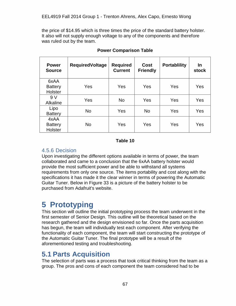
EEL4919 Fall 2014 Group 1 - Trenton Ahrens, Alex Capo, Ernesto Wong
67
the price of $14.95 which is three times the price of the standard battery holster. It also will not supply enough voltage to any of the components and therefore was ruled out by the team.
Power Comparison Table
Power Source
RequiredVoltage
Required Current
Cost
Friendly
Portablility
In
stock
6xAA Battery Holster
Yes Yes Yes Yes Yes
9 V Alkaline
Yes No Yes Yes Yes
Lipo Battery
No Yes No Yes Yes
4xAA Battery Holster
No Yes Yes Yes Yes
Table 10
4.5.6 Decision Upon investigating the different options available in terms of power, the team collaborated and came to a conclusion that the 6xAA battery holster would provide the most sufficient power and be able to withstand all systems requirements from only one source. The items portability and cost along with the specifications it has made it the clear winner in terms of powering the Automatic Guitar Tuner. Below in Figure 33 is a picture of the battery holster to be purchased from Adafruit's website.
5 Prototyping This section will outline the initial prototyping process the team underwent in the first semester of Senior Design. This outline will be theoretical based on the research gathered and the design envisioned so far. Once the parts acquisition has begun, the team will individually test each component. After verifying the functionality of each component, the team will start constructing the prototype of the Automatic Guitar Tuner. The final prototype will be a result of the aforementioned testing and troubleshooting.
5.1 Parts Acquisition The selection of parts was a process that took critical thinking from the team as a group. The pros and cons of each component the team considered had to be

EEL4919 Fall 2014 Group 1 - Trenton Ahrens, Alex Capo, Ernesto Wong
68
deeply regarded. The table provided below will outline the part picked by the team.
5.1.1 Funding A significant portion of the team‟s funds are provided by Boeing. At the beginning of Senior Design the team provided a funding proposal to both Duke Energy and Boeing. Midway through the semester the two companies got back to UCF with the supplied funding amounts. Boeing supported the Automatic Tuning Guitar with a $200.00 budget.
5.1.2 Vendors Most of the circuit components such as the MSP430, resistors, capacitors, and transistors can be obtained from Digi-key or Mouser. The pickups will be obtained from either EBay or Amazon. The motors, Bluetooth module, and external guitar tuner can also be obtained from Amazon.
5.2 Construction 5.2.1 Motor Prototyping In order to make sure the motors function correctly, the team will initially purchase a single motor to ensure it is capable of handling the highest load. This will be done in the testing lab by hooking the motor up to the bread board and supplying it with the maximum power input it can take. It will then be fitted into the peg of the thickest strings tuning key for testing. Once it is setup, the team will attempt to tune the guitar string with the ROB-12472 to ensure the motor works. If the motor proves efficient enough, the team will purchase the final 3 motors and begin the mounting process. If the motor does not work, the team will reconsider options for motors for the Automatic Guitar Tuner.
5.2.2 H-Bridge Prototyping The prototyping process for the H-Bridge will be done after the motors. Once the motors are confirmed and working, the H-Bridge will be tested with two motors at once, this is because the H-Bridge has dual compatibility. Once the H-Bridge proves to be working successfully, the team will begin to implement them on the mounting design with the motors. This process will likely be fast because the H-Bridge is such a small component that finding a place for it on the final design should not be difficult.
5.2.3 Encoder Prototyping Prototyping for the encoder will be done first by picking out a material that is highly reflective in order to get a good sensor reading. A bright white material will be purchased to first see if the sensor reads LOW. If the material tested proves to work, the team will then test different methods of how to have the sensor read a HIGH. Coloring sections of the material with a black permanent marker will be the first option tested by the team. If this color difference works, the team will cut the material into four small disks (one for each tuning peg) and will have two white sections and two black (for quarter turn resolution). If the black marker is

EEL4919 Fall 2014 Group 1 - Trenton Ahrens, Alex Capo, Ernesto Wong
69
not dark enough, the team will implement the same idea as stated above but with a different material. The second material to be tested will be black electrical tape. If this method proves to have a better response time for the sensor, the team will section the disks with tape instead.
5.2.4 Power Prototyping There are three separate components in the Automatic Guitar Tuner system that will require power. These three parts are the Bluetooth module, the MSP430 microprocessor and the DC Standard Gearmotors. Both the Bluetooth module and the MSP430 require a 3.3 V input voltage to operate and the DC motors can take an input voltage in the range of 3-9 V. The torque output of the motors will be determined by the amount of input voltage they are receiving. In order to find an ideal input voltage for the motors, the team will begin the power prototyping process by testing the motors torque output at the minimum voltage requirement. The lower power consumption the better and will thus result in a longer lasting product. If the motors are capable of turning the pegs at a low voltage, the team may modify the battery chosen and replace it for something of a lesser voltage amount. If this is not the case, the team will use either 7.5 or 9 V for the motors, and use this same source for the both the Bluetooth module and MSP430. Because the voltage required for the Bluetooth module and MSP430 are only 3.3 V, a voltage regulator will be implemented to drop down the voltage of the source, to ensure these two loads are not receiving too high of an input voltage. Once all of the components are proven to be powered by one source, the team will begin the mounting process of the power supply on the Automatic Guitar Tuner system.
5.2.5 Microcontroller Since the MSP430F5529 is being used in the project, the team can use the launchpad version to prototype the design. The launchpad has connectors that allow all the inputs and outputs to be connected to. A breadboard can be used to connect all the separate components together to test. Once the PCB has been made including the microcontroller and H-bridge's, it will be mounted on the underside of the guitar. The board will be mounted on standoffs that will be screwed into the guitar.
5.2.6 HC-05 to MSP430 The pins on the Bluetooth module, HC-05, is connected to the pins on the MSP430. It is important that whoever is handling these components must discharge him or herself to prevent damaging the components. Also, the team made sure that the VCC pins are connected last to prevent shorting the components and damaging them. After this is done, the team will proceed with the construction of the rest of the system.

EEL4919 Fall 2014 Group 1 - Trenton Ahrens, Alex Capo, Ernesto Wong
70
Basic Bluetooth module to MSP430 connection
Figure 30
5.2.7 Mobile Application The Android mobile application is constructed using Eclipse IDE from the Android SDK toolkit. While constructing the code, the mobile device is always connected through USB to the computer using Eclipse IDE. By doing this, the transferring of files, debugging the code, and testing the functionality of the GUI will be easy and convenient.
5.3 PCB Vendor Our project will require at least two different printed circuit boards. One for the microprocessor and a second for the motors. There are many different manufactures to obtain PCB's from.
5.3.1 OSH Park OSH Park offers two layer PCB's for $5 per square inch. They have a turn time of about 12 calendar days and can be ordered from their site. They also offer four layer boards for $10 per square inch. They have a turn time of about twelve weeks and can also be ordered from their site. OSH Park also includes three copies of each PCB for both of these options
OSH Park has different specifications for the different amount of board layers. The two layer boards are 1.6mm thick and have 1 ounce of copper on both side. The minimum specs are 6 mil traces with 6 mil spacing, and 13 mil drills with 7 mil annular rings. They have ENIG finish and are FR4 170tG/290Td which are suitable for lead-free processes and temperature.
The 4 layer boards are FR408 (180Tg). They also have ENIG finish for excellent solderability and environmental resistance. They are 1.6mm thick and have 1 ounce copper on both sides. The internal copper is 0.5 ounce. The minimum

EEL4919 Fall 2014 Group 1 - Trenton Ahrens, Alex Capo, Ernesto Wong
71
specs are 5 mil traces with 5 mil spacing, and 10 mil drills with 4 mil annular rings. Internal cutouts are supported for both boards, but Plated slots are not supported.
OSH Park allows PCB's to be designed using Eagle CAD. They are currently processing uploaded Eagle BRD files with Eagle CAD version 6.6 and are compatible with all Eagle versions up to 7.1
5.3.2 4PCB 4PCB by Advanced Circuits has special discounts for students. They offer 2 layer full spec boards for $33 each. They have 4 layer full spec boards for $66. They do not require a minimum quantity when ordering. Advanced Circuits has their own PCB layout software that can be used to design the PCB.
4PCB also offers a PCB file check. A PCB design software file can be uploaded to receive a free design file report. An email will be received within minutes that will identify any problems with the design that will affect manufacturability. This ensures that all designs meet fabrication specifications and all required files are included.
5.3.3 Software Some PCB manufactures offer free PCB design software like 4PCB. There are other programs available to design PCB's. Eagle CAD has software available for students for $160. They also have a free version available. The only limitations of the free version are that it must be 100 x 80 mm, can only have two signal layers (top and bottom), and the schematic editor can only create one sheet.
5.4 Coding This section will describe the architecture of the coding of the mobile application and microcontroller. This section will outline the original design and layout of the source codes used in this project.
5.4.1 Android SDK The code for the Android mobile application is compiled using the Android SDK. The Android SDK provides the API libraries and developer tools necessary to build, test, and debug apps for Android. The code is written using Java programming language. The team figured this tool kit would be an ideal choice for this project, seeing that the provided features are very useful for the task at hand. The numerous amount of tools provided will make constructing the code for the mobile application easy. The official IDE is Eclipse using Android Development Tools Plugin and is what the team will use as the integrated development environment. When constructing the code for the Bluetooth connection, the mobile device will be connected at all times. This will help see how the code affects the device as it is constructed. By doing this, the team will be able to see the progress of the code and fix any errors along the way [13].
EEL4919 Fall 2014 Group 1 - Trenton Ahrens, Alex Capo, Ernesto Wong
72
5.4.2 Mobile Application GUI Within Eclipse, first the team needs to layout the GUI to the desired layout design. This includes dragging and dropping buttons, text fields, and scroll down menus to match the desired layout illustrated below. This is done within the Main.xml file under the Graphical Layout tab. With all the fields laid out, the team can then assign the functions for each corresponding field within the Main.java file in Eclipse.
TextField1 will contain the string of the title for the mobile app. “Automatic Guitar Tuner” will be the string used
TextField2 will contain the string “Select tuning preference”
DropdownMenu1 will contain all 5 fields corresponding to each of the 5 tuning preferences, Standard Tuning (E-A-D-G from lowest string to highest string), Drop D tuning (D-A-D-G), Drop B tuning (B-A-D-G) Semitone Flat Standard tuning (Eb-Ab-Db-Gb), and Semitone Flat Drop D tuning (Db-Ab-Db-Gb).
Button1 will initiate the automated process of the selected tuning preference. The text of Button1 displays “Start”. Pressing Button1 will change to a screen that will prompt the user to pluck the first string upon pressing Button1.
Button2 on the home screen will exit the application. The text “Exit” is used to label Button2. Button2 on the next screen will cancel the automatic tuning process and will return the user back to the home screen.
Button3 is used to search and connect to Bluetooth enabled devices within close proximity. This will initialize the discovery method
In the Main.xml tab under Main.xml, all the text fields, buttons, and dropdown menu will be listed along with their layout ID, layout width, layout height, text, and other layout characteristics. Here the team can change the characteristics to match the desired layout design
5.4.3 Bluetooth Functionalities For the mobile application, it first needs to check if the device using the app has Bluetooth capabilities. The team first needs to access the Android Manifest Permissions and enable users permissions and save it.The team then needs to create classes to set up the buttons, the ListView, and the array adapter that is associated with the ListView for the Bluetooth connection. Under the public class Main Activity, a string ArrayAdapter, a button, preferably named connectNew, a Listview, and a BluetoothAdapter is made and imported. A method for initialization is then made to initialize the first button, listview, listadapter, and BluetoothAdapter by their assigned class names. BluetoothAdapter will get the default adapter and run a check to see if it is null, or if the data value doesn‟t exit. A conditional statement will take of this and will return a message telling the user that no Bluetooth can be detected. If Bluetooth is detected, BluetoothAdapter will

EEL4919 Fall 2014 Group 1 - Trenton Ahrens, Alex Capo, Ernesto Wong
73
request to enable Bluetooth. The option to cancel this process also needs to be implemented in case the user decides to cancel the action.
When scanning for new devices, a Broadcast receiver class is used, however the Broadcast receiver needs to be filtered in order to perform certain actions. The team does so by creating and initializing a Broadcastreceiver class and filter class. The filter class will filter for IntentsACTION_DISCOVERY_STARTED, ACTION_DISCOVERY_FINISHED, and ACTION_STATE_CHANGED and they are registered to the receiver. Under the onReceive method, the Intents will perform the actions assigned to them.
ACTION_DISCOVERY_STARTED– code that will initialize the automatic tuning process on the microcontroller and the bass.
ACTION_DISCOVERY _FINISHED–checks if discovered device are already paired by the mobile device
ACTION_STATE_CHANGED – action for when the state of Bluetooth connectivity changes. Turn on Bluetooth
A method is then created upon receiving a signal from a new device. At the same time, the method will add the new device to the array of devices stored in memory and also activate the Bluetooth. It will also call out other functions upon receiving signal from the other device; in this case the code to initialize the automatic tuning process on the bass. The team also needed to add an „unregister the receiver‟ on the pause method in order to prevent the code from crashing.
Next the app needs to recall any previously paired connections. This will prevent having to constantly request permission to previously paired devices. The team will do this by creating an array of devices that can be stored into memory. The getPairedDevices method will first check for non-null values in the array instead of wasting time checking for null values. Then listadapter will add device to the array of devices. A string of array list will need to be created in order to list the names of devices being stored.
To start discovering devices, the startDISCOVERY method method will immediately return with a boolean indicating whether discovery has successfully started. The discovery process usually involves an inquiry scan of about 12 seconds, followed by a page scan of each found device to retrieve its Bluetooth name. For each device, the system will broadcast the ACTION_FOUND Intent. This Intent holds the extra fields, EXTRA_DEVICE and EXTRA_CLASS, containing a BluetoothDevice and a BluetoothClass, respectively. A method called onItemClick is made to perform the action once the search Bluetooth devices button is pressed.The application needs to display what devices are paired and display a check mark next to paired devices. The team does so by using a for loop to cycle through the device array and check one by one which devices are paired [14].

EEL4919 Fall 2014 Group 1 - Trenton Ahrens, Alex Capo, Ernesto Wong
74
Bluetooth Permission Request
Figure 31
Example of Screen of Listed Bluetooth Devices
Figure 32
The mobile device serves as the client and Bluetooth module connect to the microcontroller is the server. In order to initiate a connection with theBluetooth module,the Bluetooth Deviceobject that represents the Bluetooth module must first be obtained. The BluetoothDevicethen acquires aBluetoothSocket, the connection point that allows the application to exchange data with another Bluetooth device, and initiate the connection.Using the BluetoothDevice, the team obtains the BluetoothSocket by calling the createRfcommSocketToServiceRecord(UUID). This initializes
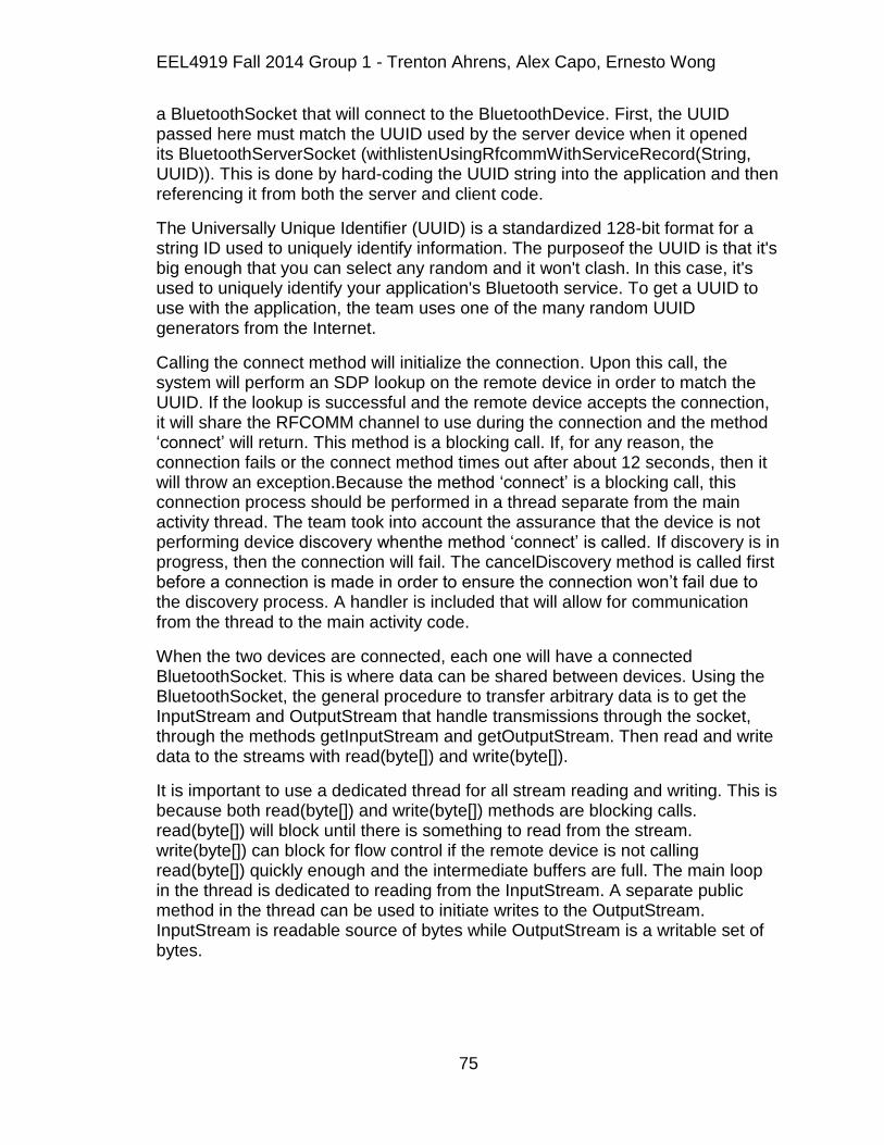
EEL4919 Fall 2014 Group 1 - Trenton Ahrens, Alex Capo, Ernesto Wong
75
a BluetoothSocket that will connect to the BluetoothDevice. First, the UUID passed here must match the UUID used by the server device when it opened its BluetoothServerSocket (withlistenUsingRfcommWithServiceRecord(String, UUID)). This is done by hard-coding the UUID string into the application and then referencing it from both the server and client code.
The Universally Unique Identifier (UUID) is a standardized 128-bit format for a string ID used to uniquely identify information. The purposeof the UUID is that it's big enough that you can select any random and it won't clash. In this case, it's used to uniquely identify your application's Bluetooth service. To get a UUID to use with the application, the team uses one of the many random UUID generators from the Internet.
Calling the connect method will initialize the connection. Upon this call, the system will perform an SDP lookup on the remote device in order to match the UUID. If the lookup is successful and the remote device accepts the connection, it will share the RFCOMM channel to use during the connection and the method „connect‟ will return. This method is a blocking call. If, for any reason, the connection fails or the connect method times out after about 12 seconds, then it will throw an exception.Because the method „connect‟ is a blocking call, this connection process should be performed in a thread separate from the main activity thread. The team took into account the assurance that the device is not performing device discovery whenthe method „connect‟ is called. If discovery is in progress, then the connection will fail. The cancelDiscovery method is called first before a connection is made in order to ensure the connection won‟t fail due to the discovery process. A handler is included that will allow for communication from the thread to the main activity code.
When the two devices are connected, each one will have a connected BluetoothSocket. This is where data can be shared between devices. Using the BluetoothSocket, the general procedure to transfer arbitrary data is to get the InputStream and OutputStream that handle transmissions through the socket, through the methods getInputStream and getOutputStream. Then read and write data to the streams with read(byte[]) and write(byte[]).
It is important to use a dedicated thread for all stream reading and writing. This is because both read(byte[]) and write(byte[]) methods are blocking calls. read(byte[]) will block until there is something to read from the stream. write(byte[]) can block for flow control if the remote device is not calling read(byte[]) quickly enough and the intermediate buffers are full. The main loop in the thread is dedicated to reading from the InputStream. A separate public method in the thread can be used to initiate writes to the OutputStream. InputStream is readable source of bytes while OutputStream is a writable set of bytes.

EEL4919 Fall 2014 Group 1 - Trenton Ahrens, Alex Capo, Ernesto Wong
76
6 Testing This section will describe the different aspects of testing the prototype. This section will include adhering to safety, testing environment and test procedure. This will be the guidelines to properly test the system.
6.1 Safety Safety is the number one priority when constructing the project. The team addressed all the potential hazards that associate with this project. The following guidelines helped avoid injuries.
6.1.1 Soldering Iron A soldering iron can reach temperatures up to 400°C. Hold wires to be
heated with clamps or tweezers. Never directly touch the tip of the soldering iron. Keep all flammable materials out of reach of the iron.
Return the soldering iron when to its stand when not in use. Turn off
soldering iron when not in use for extended periods of time.
Wear eye protection to avoid injuries to the eyes due to flying debris when
soldering
Avoid toxic fumes. Work in a well-ventilated area. Become familiar with all
material involved and read the MSDS (Material Safety Data Sheet).
6.1.2 Power Tools Avoid touching any moving mechanical parts when using power tools.
Loose clothing, hair, and jewelry should be tucked in and away from
moving parts.
Avoid eye injuries from flying debris by wearing eye protection.
Turn off all power tools that are not in use.
Practice proper handling of power tools.
6.1.3 Electrical components Before handling any piece of electrical component, one must discharge
him or herself of static electricity that can seriously damage a component
(ie. a Chip, Processor)
Avoid short circuits by making sure all ground leads to the same point.
Never touch two pieces of equipment simultaneously.
Avoid electrical shocks by turning off the power when handling
components. Turn off power when assembling and disassembling project.
Avoid heat dissipating surfaces of high wattage resistors and loads
because they can cause severe burns.
Make sure hands are dry. Never handle wet, damp, or ungrounded
equipment

EEL4919 Fall 2014 Group 1 - Trenton Ahrens, Alex Capo, Ernesto Wong
77
6.1.4 Bluetooth Radiation The team thought it was necessary to limit the exposure of radiation from Bluetooth devices. The amount of radiation emitted from Bluetooth devices depend on the type of class.
Class 1 transmitter – The most powerful emitter. Ranges up to 100 meters (300 ft.) with transmission power of 100 mW.
Class 2 transmitter – Less powerful than Class 1. Ranges up to 10 meters (30 ft.) with transmission power of 2.5mW
Class 3 transmitter – The least powerful class. Emits the lowest level of radiation. Ranges less than 10 meters (30 ft.) with transmission power of 1mW.
To avoid severe electrical sensitivity symptoms, the team used a Class 2 or Class 3 transmission and avoided Class 1 transmitters. There is no sense in using a range of up to 100 meters for this project.
6.2 Testing Environment Testing is an important part of the project. Thorough testing is required to ensure that the final project works properly and has no bugs. A test procedure shall be created to ensure that all parts of the project are tested thoroughly and that all the objectives are met.
6.2.1 Test Procedure The first part of a good test procedure is a good test strategy. The objective of this test procedure is to ensure that the project is properly working and all bugs have been address and fixed. When testing, the team aims to ensure all the previously set objectives are met. Any problems or errors that arise will be noted and taken care of. The team must be especially careful not to cause any damage to any components, for it can delay the project completion. The best way to approach testing the project would be to split the test up between the different subsystems. After all the subsystems are tested, then the project can be tested as a whole. This will ensure that some smaller bugs can be found within the subsystems. When testing the project as a whole it is harder to see what is occurring between the different parts. One subsystem to be tested is the motors. Once the motors are selected and purchased it is important to ensure that they work properly. Once they are installed they shall be tested in the mounts. It is important that during this step that the guitar strings are not installed to avoid breaking the strings and possible injury. Ensure that the motor is able to turn the peg and would be able to tighten or loosen the string if they were installed. Once the microcontroller is working and installed, it is important to make sure that the motors are receiving a signal from the board when it is sending a signal to tune the strings.
EEL4919 Fall 2014 Group 1 - Trenton Ahrens, Alex Capo, Ernesto Wong
78
Once the power supply is built, it also should be tested. The circuits that supply power to the microcontroller and the motors should be tested to make sure they supply the correct voltages and current. This will ensure that no damage is done to them once powered on. Once the power supply has been tested and is working properly, it should be tested by running the motors under load to make sure that it can handle the current draw. Once the microcontroller is received it should be tested to make sure that it operates correctly. It should be programmed with the code for the project and tested to see if the code executes correctly. Once the board is installed onto the guitar, ensure that the board is communicating correctly with the other sub-systems. The motors should be receiving the proper signal to tighten or loosen the string based on the frequency of the string. The board should be communicating with the Bluetooth module to receive information from the mobile device. The Bluetooth module needs to be tested to ensure proper communication between the microcontroller and the application on the mobile device. Once installed, test the module to make sure it powers up. Once on check to see if the device is correctly communicating with the microcontroller and the mobile device. Once the mobile application has been created and installed, it needs to be tested for bugs. Once installed, make sure that the phone is able to pair successfully with the Bluetooth module. Once paired try testing the functions of the application and check whether the microcontroller receives the commands or not. Once the pickups have been installed onto the guitar and wired to the proper circuits, they also need to be tested. The user will pluck each string and check the microcontroller to ensure that the proper signal is being received. Any unwanted noise or static will have to be eliminated in order to achieve a clean and clear sound. That would mean re-wiring and re-soldering. Once all the different subsystems have been tested the project must be tested as a whole. Power on the microcontroller and connect the mobile phone to the Bluetooth module. Once everything is on and running, the first string will be plucked string to make the string is being tuned automatically. Once the string is finished being tuned, test the remaining strings. After all four strings have been tested, use an external guitar tuner to compare the desired tuning to what is actually measured. The procedure is then repeated using the mobile application for the rest of the tuning presets. Test the guitar again to see if it tunes to the new desired frequencies. Once finished test again with an external guitar tuner. Check for the following when testing.
Did the device power up correctly?
Did the device connected to the correct device(s)?
Is the proper data/signal being transmitted/received?
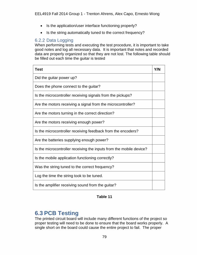
EEL4919 Fall 2014 Group 1 - Trenton Ahrens, Alex Capo, Ernesto Wong
79
Is the application/user interface functioning properly?
Is the string automatically tuned to the correct frequency?
6.2.2 Data Logging When performing tests and executing the test procedure, it is important to take good notes and log all necessary data. It is important that notes and recorded data are properly organized so that they are not lost. The following table should be filled out each time the guitar is tested
Test Y/N
Did the guitar power up?
Does the phone connect to the guitar?
Is the microcontroller receiving signals from the pickups?
Are the motors receiving a signal from the microcontroller?
Are the motors turning in the correct direction?
Are the motors receiving enough power?
Is the microcontroller receiving feedback from the encoders?
Are the batteries supplying enough power?
Is the microcontroller receiving the inputs from the mobile device?
Is the mobile application functioning correctly?
Was the string tuned to the correct frequency?
Log the time the string took to be tuned.
Is the amplifier receiving sound from the guitar?
Table 11
6.3 PCB Testing The printed circuit board will include many different functions of the project so proper testing will need to be done to ensure that the board works properly. A single short on the board could cause the entire project to fail. The proper
EEL4919 Fall 2014 Group 1 - Trenton Ahrens, Alex Capo, Ernesto Wong
80
precautions must be taken to ensure that there is no noise or interference between subsystems as well. Visual inspection will be done to check for obvious imperfections and defects.
Once the components are installed they need to be inspected also. This inspection is crucial as it is where mistakes can easily be made. Small surface mount components can easily be mixed up. Check for obvious shorts from soldering between components. The components should be inspected to ensure that the correct components are in the correct places and that they are also the correct values. Ensure that the microprocessor is oriented correctly especially if the chip has an equal number of pins on all sides. Incorrect orientation of the processor could be catastrophic. Processors usually have a notch or indentation to indicate orientation. This should match what is in the design and sometimes indicated on the board.
7 Administrative Content
7.1 Milestones The team would spend many meetings discussing the every aspect of this project. These meetings were either brief or extensive depending on the topic or agenda. The team would discuss ideas and delegate tasks in order to complete this project in a timely manner. Focus and productivity are the main goals for completion of the project with correspondence to the guidelines discussed in Senior Design lectures.
7.1.1 Establishing an Idea The first major milestone for the team was to settle for a project idea that ever member would agree on. Through continuous brainstorming, the team noticed a shared interest in guitars and music in general. The team finally decided to integrate this common interest and the teams engineering background into an idea of a self-tuning bass guitar. This idea was then set to be the overall goal of the project. The team recognized the tasks and challenges ahead and created a proposal for the project idea.
From feedback on the proposal, the team was lacking one aspect of the project. Originally, our project would require a user to set a tuning preference on an LED screen and then pluck each individual string to automatically tune the guitar. The team was lacking a software/digital aspect of the project and the original proposal was rejected. To fix this, one member proposed that instead of using an LED screen as the user interface, the user would select the tuning preferences through a mobile device and have it communicate through Bluetooth. This would then add more software to the project, as well as a new challenge. Integrating a mobile device as a user interface into the project was the last feature needed for approval in order to continue.

EEL4919 Fall 2014 Group 1 - Trenton Ahrens, Alex Capo, Ernesto Wong
81
7.1.2 The Research Process Research is the second major stepping stone for this project‟s completion. This process was detailed oriented to make sure the team‟s approach is organized and accurate. During this process, the team was able to first practice planning and collaborating together as a team. The team recognized the task at hand and divided the work evenly with no hassle. Each team member set aside time to commit to the research towards the Automatic Guitar Tuner. About 10-15 hours a week was dedicated to research by each member of the team. All together, the information gathered set the foundation for the design and testing process.
7.1.3 Design The next major milestone was to come up with a design for the project. Upon collaborating on a single and final design, the team combined the information each member gathered through research. Through information gathering, the team also stumbled across similar designs for a similar project done in the past by other students from other universities. The team used these designs as references to create an original design for the project.
The next step was to map out the individual subsystems of the project and assign who would be responsible for each subsystem. This was necessary to help visualize the flow of operation for the entire system. Once this was established, more in-depth research was done by each member in correspondence to their subsystem responsibilities.Slowly, the research and information gathered turned into one final design layout that will act as the team‟s blueprint for prototyping.
7.1.4 Prototyping and Testing Once the team established the blueprint for the project, the team began building and testing the design for the Automatic Guitar Tuner. This was the team‟s next major milestone. The team acquired the parts and components through online retailers and stores using the funds provided by Boeing. Numerous days were spent selecting the proper parts and constructing the device. Tedious hours were set aside soldering, cutting, measuring, and screwing together components that will be the team‟s project. Even more hours were spent coding and debugging the device in order to achieve the desired functionality.
Through hard work, the team was finally able to test the finished the device. Though it was expected that errors would arise the first time around, the team kept their heads up high and overcame the hardships of debugging and adjusting the device in order for the device to function properly. The team ran through the check list of desired objectives in order to make sure they were in compliance with the goals. Whenever a problem or error would come up, it was back to the drawing board with the design. The team was prepared for the arising problems and was able to compensate and fix whatever needed to be fixed. In the end, the team achieved the overall goal and constructed the Automatic Guitar Tuner.

EEL4919 Fall 2014 Group 1 - Trenton Ahrens, Alex Capo, Ernesto Wong
82
Hours Spent on Project
Alex Ernesto Trenton
Research 15 hrs/week 15 hrs/week 15 hrs/week
Constructing 20 hrs/week 10 hrs/week 15 hrs/week
Coding 10 hrs/week 25 hrs/week 10 hrs/week
Testing/Debugging 17 hrs/week 20 hrs/week 20 hrs/week
Table 12
7.2 Budget The team‟s budget was possibly the most important factor of the project as a whole. With a $200.00 fund provided by Boeing, the team immediately understood that finding cost friendly components were a must. If the situation occurs where the budget provided by Boeing proved to be insufficient, the team would come together with and look for additional options and resources before spending extra money. If the options available would not make ends meet in terms of requirements from the design, the team would deposit money from their own pockets in order to have a high quality design, so that the user could get the best experience possible. Below will show a table of the starting budget and the items picked by the team. It will also show the cost of each component and the deduction made after purchase.
Budget List
Description
Price
Balance
Starting Budget
$200.00
ROB-12472 (x4)
$79.80
$120.20
Adafruit 6xAA Holster
$5.00
$115.20
Energizer 8xAA NiMH Batteries
$20.56
$95.64
HC-05 Bluetooth Module
$10.00
$85.64
MSP 430
$8.06 $77.58

EEL4919 Fall 2014 Group 1 - Trenton Ahrens, Alex Capo, Ernesto Wong
83
Power Gig Guitar Pickups $45.99 $31.59
PCB $33.00 -$1.41
QTR-1RC (x4) $8.50 -$9.91
L293DNE (x2) $7.50 -$17.41
Miscellaneous Components
$10.00 -$27.41
Table 13
8 Final Design Decisions The end project was designed very similarly to the original proposed design with only a few minor changes. The original designs did not have any major flaws, only requiring a few minor tweaks.
8.1 Pickups Alternative The first change to the project was the use of the original pickups. The original plan was to install polyphonic pickups under each of the four strings on the guitar. However, this would require removing some of the wood on the guitar. This would not only be complicated, but also could change the sound of the guitar. Any adjustments to the wood on the guitar can cause the sound of the guitar to be changed. After some testing, it was determined that the original pickups worked well enough. The signal obtained from the guitar was clean enough to be used by the ADC. Below is a waveform of the guitar signal.
Guitar Waveform
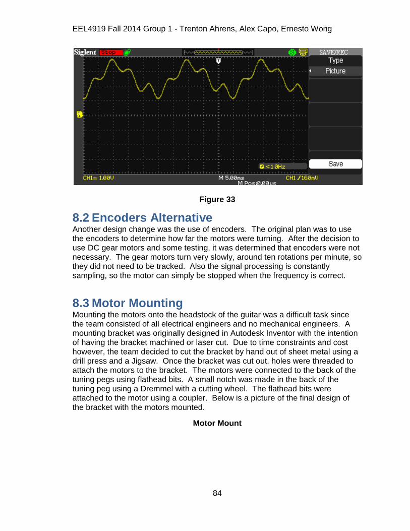
EEL4919 Fall 2014 Group 1 - Trenton Ahrens, Alex Capo, Ernesto Wong
84
Figure 33
8.2 Encoders Alternative Another design change was the use of encoders. The original plan was to use the encoders to determine how far the motors were turning. After the decision to use DC gear motors and some testing, it was determined that encoders were not necessary. The gear motors turn very slowly, around ten rotations per minute, so they did not need to be tracked. Also the signal processing is constantly sampling, so the motor can simply be stopped when the frequency is correct.
8.3 Motor Mounting Mounting the motors onto the headstock of the guitar was a difficult task since the team consisted of all electrical engineers and no mechanical engineers. A mounting bracket was originally designed in Autodesk Inventor with the intention of having the bracket machined or laser cut. Due to time constraints and cost however, the team decided to cut the bracket by hand out of sheet metal using a drill press and a Jigsaw. Once the bracket was cut out, holes were threaded to attach the motors to the bracket. The motors were connected to the back of the tuning pegs using flathead bits. A small notch was made in the back of the tuning peg using a Dremmel with a cutting wheel. The flathead bits were attached to the motor using a coupler. Below is a picture of the final design of the bracket with the motors mounted.
Motor Mount
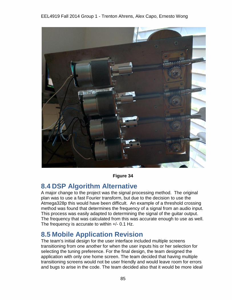
EEL4919 Fall 2014 Group 1 - Trenton Ahrens, Alex Capo, Ernesto Wong
85
Figure 34
8.4 DSP Algorithm Alternative A major change to the project was the signal processing method. The original plan was to use a fast Fourier transform, but due to the decision to use the Atmega328p this would have been difficult. An example of a threshold crossing method was found that determines the frequency of a signal from an audio input. This process was easily adapted to determining the signal of the guitar output. The frequency that was calculated from this was accurate enough to use as well. The frequency is accurate to within +/- 0.1 Hz.
8.5 Mobile Application Revision The team's initial design for the user interface included multiple screens transitioning from one another for when the user inputs his or her selection for selecting the tuning preference. For the final design, the team designed the application with only one home screen. The team decided that having multiple transitioning screens would not be user friendly and would leave room for errors and bugs to arise in the code. The team decided also that it would be more ideal

EEL4919 Fall 2014 Group 1 - Trenton Ahrens, Alex Capo, Ernesto Wong
86
for the user interface to only pair with the Bluetooth module on the Automatic Guitar Tuner. The team hardcoded the MAC address of the module into the code, thus avoiding pairing with any Bluetooth device that doesn't pertain to the project. In the final design, the home screen layout consists of the five buttons for the each tuning preference. Upon selecting a preference, a message pops up at the bottom of the screen indicating that the corresponding preference has been selected. It is also an indicator for the user to commence plucking the first string. Below in Figure 35 is the final design for our application home screen.
Automatic Guitar Tuner Home Screen
Figure 35
8.6 The Final Design The final design came out to be almost exactly what was anticipated. The only adjustments were the aforementioned technical decisions, as well as the location of the PCB on the final design. It was originally intended to be mounted on the body of the guitar, however to eliminate unnecessary wire mess, it was placed on

EEL4919 Fall 2014 Group 1 - Trenton Ahrens, Alex Capo, Ernesto Wong
87
the head of the guitar on the mount with the motors. To ensure that the PCB would be unaffected from any outside interaction, an acyclic casing was designed using Maker Case, and then created at the T.I. lab in the UCF engineering atrium. This provided protection for the PCB and also allowed access to it for any future adjustments to the hardware on board. Below in Figure XX is the final design of the Automatic Guitar Tuner.
Figure 36
9 Summary and Conclusion The senior design project is a final measurement of our knowledge that we‟ve gained during our time at the university in the college of engineering. The team is

EEL4919 Fall 2014 Group 1 - Trenton Ahrens, Alex Capo, Ernesto Wong
88
expected to demonstrate everything that they have learned during their coursework. As engineering students, the team is naturally curious, especially in electronics. During the time spent at UCF, the team had the urge to apply their knowledge to the real world problems. To undertake some projects however, certain courses must be taken to obtain the knowledge required. Now that the team is close to graduation, the team has sufficient knowledge to tackle real challenges. The team spent the first semester of senior design researching and designing the Automatic Guitar Tuner. Extensive research was done on the individual portions of the project. The team divided up parts of the project to be researched and designed individually. The team held frequent meetings to stay current on the progress of the project. When issues arose, the team tackled them as a unit to make sure that they all had a proper understanding of the issue. Once the issue was solved, the team would split back up into their individually assigned research and development. The process took up a majority of the semester and once it was finished the team constructed the term paper document. By reading through this document, the user should understand how the Automatic Guitar Tuner works and how to operate it. The second semester of senior design was spent designing and actually building the project. The three team members each worked on individual subsystems of the project and then combined them all for the final design at the end. When problems arose they were dealt with by their respective team member, or by the entire team if the problem required the work of the entire team to solve. During the design and build of the project, the team members learned many practical skills. Often times there were extraneous additions on the project that were determined to be unnecessary after building and testing. The team hopes to take the newly gained knowledge and experience into the work field after graduation. From circuit design to programming design, the skill acquired from this project will serve useful, for it is necessary in the engineering field. Critical thinking and problem solving are the main skills necessary for engineering. The team is satisfied with the work they put into this project to achieve these skills.

EEL4919 Fall 2014 Group 1 - Trenton Ahrens, Alex Capo, Ernesto Wong
i
10 Appendices
10.1 Appendix A – References [1] “Calculating Cents” Internet:
http://hyperphysics.phy-astr.gsu.edu/hbase/music/cents.html#c2, [October 2014]
[2] “How to Choose the Right Strings for your Bass Guitar” Internet:
http://thehub.musiciansfriend.com/bass-guitar-buying-guide/how-to-choose-the-right-strings-for-your-bass-guitar, [February 2014 ]
[3] “Piezo Pickup Diagram” Internet:
https://www.flickr.com/photos/omegatron/129267668 , [April 2006] [4] “Pickups (Music Technology)” Internet:
http://en.wikipedia.org/wiki/Pickup_%28music_technology%29, [November 2014]
[5] “The Secret of Accuate Tuner for Windows…” Internet:
http://wmpoweruser.com/the-secret-of-accurate-tuner-for-windows-phone-it-works-like-a-human-ear, [July 2012]
[6] “Bluetooth Device Access Guide” Internet:
https://developer.apple.com/library/mac/documentation/DeviceDrivers/Conceptual/Bluetooth/BT_Bluetooth_Basics/BT_Bluetooth_Basics.html [June 2012]
[7] “Catalog Supplement…” Internet;
http://www.daddario.com/upload/tension_chart_13934.pdf,
[8] “How Much Tension to Break an E-String” Internet;
http://www.talkbass.com/threads/how-much-tension-to-break-an-e-string.749742/, [March 2011]
[9] “Standard Gearmotor” Internet;
https://www.sparkfun.com/products/12472,
[10] “Dual H-Bridge” Internet;
http://commons.wikimedia.org/wiki/File:L293DNE_Dual_H-bridge.jpg, [March 2014]
[11] “Orcad Capture Library for HC Seried Bluetooth Modules” Internet;
http://www.123mylist.com/2013/11/orcad-capture-library-for-hc-series.html, [November 2013]

EEL4919 Fall 2014 Group 1 - Trenton Ahrens, Alex Capo, Ernesto Wong
ii
[12] “Electric Bass Signals” Internet;
http://www.cafewalter.com/cafewalter/signals/basssignals.htm, [April 2000]
[13] “Setting up Eclipse and Android SDK on openSUSE 11.3” Internet;
http://thsundel.blogspot.com/2010/08/setting-up-eclipse-and-android-sdk-on.html, [August 2010]
[14] “Android Connectivity” Internet;
http://www.codeproject.com/Articles/814814/Android-Connectivity, [September 2014]
10.2 Appendix B – Copyright Permissions Texas Insruments
Samsung
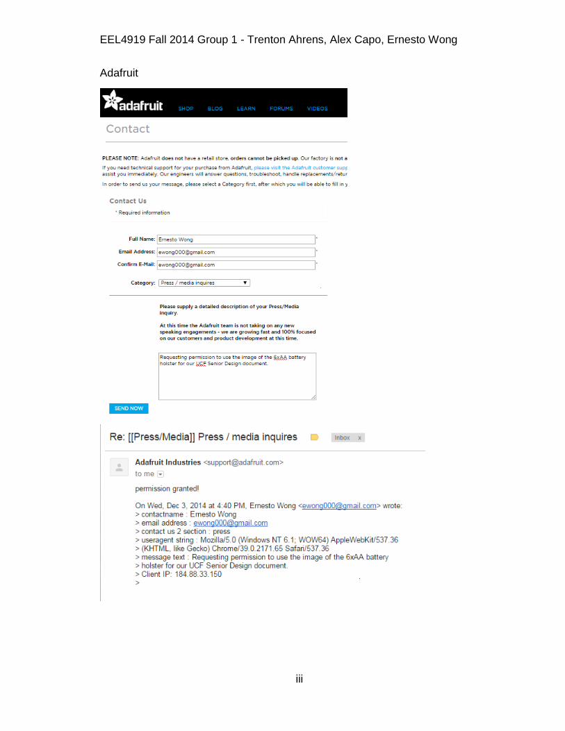
EEL4919 Fall 2014 Group 1 - Trenton Ahrens, Alex Capo, Ernesto Wong
iii
Adafruit

EEL4919 Fall 2014 Group 1 - Trenton Ahrens, Alex Capo, Ernesto Wong
iv
Sparkfun
D‟Addario