automatic controlst automatic controls printed in japan 2018.12 z shinjuku garden tower 22f 8-2,...
TRANSCRIPT

T
AUTOM
ATIC CON
TROLS
Printed in Japan2018.12 z
Shinjuku Garden Tower 22F8-2, Okubo 3-chome, Shinjuku-ku, Tokyo, 169-0072 JapanTel : +81 3 6205 9123 Fax : +81 3 6205 9125E-mail : [email protected] : http://www.saginomiya-global.com/en/
AutomaticControls
REFERENCE INFORMATIONAPPROVAL STANDARD LIST
PRESSURE CONTROLSTEMPERATURE & HUMIDITY CONTROLS
PRESSURE & TEMPERATURE CONTROLS INFORMATIONEXPANSION VALVES
SOLENOID VALVES & CONTROL VALVESOTHER VALVES
OTHER CONTROL EQUIPMENT
背幅:7.2mm(本文132p)
英文総合カタログ_T 表1/表4 4c
2018.12改訂 T版_Gai

英文総合カタログ_T 表2/表3 1c
2018.12改訂 T版_Gai
背幅:7.2mm(本文132p)
FOSHAN HUALU AUTOMATICCONTROLS LIMITED (China)No.59&61, Wenhua Nan Road, Chancheng DistrictFoshan, Guangdong, ChinaSales & ManufacturingTel: +86 757 8383 1558 Fax: +86 757 8383 1218
RIMSA SAGINOMIYA, S.A. DE C.V. (Mexico)Av. Central No. 126, Parque IndustrialToluca 2000, Km. 52.8 Carretera TolucaNaucalpan, C. P. 50200, Toluca, Edo. deMexico, MexicoSalesTel: +52 722 279 3680 Fax: +52 722 279 0234
Danfoss Saginomiya Sp. z o.o. (Poland)ul. Chrzanowska 5, 05-825 GrodziskMazowiecki, PolandManufacturingTel: +48 22 7550 500 Fax: +48 22 7550 505
SAGINOMIYA EUROPE Sp. z o.o. (Poland)Aleje Jerozolimskie 212 02-486 Warsaw, PolandSalesTel: +48 22 101 30 00 Fax: +48 22 101 30 01
SAGINOMIYA AMERICA, INC. (USA)655 Metro Place South suite 700, Dublin Ohio 43017, U.S.A. SalesTel: +1 614 766 7390 Fax: +1 614 766 7391
Saginomiya (Thailand) Co., Ltd. (Thailand)159 Serm-mit Tower 19th Fl., Room No.1903/1Sukhumvit 21 Rd., Klongtoey-NuaWattana, Bangkok 10110, ThailandSales & ManufacturingTel: +662 260 8364 Fax: +662 260 8366
Shinjyuku Garden Tower 22F8-2, Okubo 3-chome, Sinjyuku-kuTokyo, 169-0072 JapanTel : +81 3 6205 9123 Fax : +81 3 6205 9125E-mail: [email protected]
OVERSEAS NETWORK
First edition 1975. 4 Z
WARNINGFailure to read and follow all instruction carefully before installing or operation the product could cause personal injury and/or property damage.
Specifications are subject to change without notice.
CONSENT RELATED TO DISCLAIMERS
Revsion1(2014.12) 2014.10
We, SAGINOMIYA SEISAKUSHO, INC., (hereinafter referred to as “Saginomiya”), truly appreciate your choosing Saginomiya’s products (hereinafter referred to as “Products”).When the Products are used, this document as provided below shall be applicable except to the extent that there is anything to the contrary in any applicable estimate, agreement, catalogue, specification, etc.
CONFIRMATION OF OPERATIONAll customers using the Products (hereinafter referred to as “Customers”) are requested to, after properly installing the Products, test the operation of the Products to confirm that all the systems in connection with the Products fully function.In order to prevent the occurrence of bodily injury, fire accidents, serious damage, etc., in connection with the Customers’ machinery or equipment due to improper installation of the Products, Saginomiya kindly requests the Customers to take the necessary safety measures by preparing safe designs such as a fail-safe design (*1) and a fire spread prevention design, as well as to make the proper adjustments for product reliability necessary for fault-tolerance (*2).
(*1) Fail-safe design: Design to ensure safety in the event of any mechanical failure(*2) Fault-tolerance: Utilization of redundancy technology
Periodic Inspection of the ProductsBe sure to confirm the proper operation of the Products and keep records of such operation at least once a year.
Saginomiya shall be held harmless and be indemnified by the Customers from any damages incurred due to the Customers failing to conduct the above operational procedures, provided, however, that, this shall not apply if the damages which the Customers incurred due to the defect of the Products caused by Saginomiya.
RESTRICTIONS OF USEThe Products are designed and manufactured for the purpose of using them for cooling and heating and refrigerating appliances and air conditioning equipment or various industrial equipment, but are not designed and manufactured for the purpose of using the Products for any instrument or system related to human life or health purposes.Therefore, the use of the Products in fields related to items (1) through (3) below is not intended whatsoever. Saginomiya shall be held harmless and be indemnified from any and all damages incurred by use of the Products under item (3).
(1) In any field related to nuclear power and radiation;(2) In any field related to space or seafloor equipment;(3) In any equipment or device requiring a high degree of reliance on such equipment or device with respect to which it is reasonably foreseeable that failure or malfunction of the equipment or device would either directly or indirectly cause serious damage to human life, health or property;
Also, when using the Products under the fields related to items (1) through (9) below (except for item (3), in relation to which the Products must never be used), please be sure to notify our Saginomiya’s contact desk in charge of sales and obtain Saginomiya’s prior written approval for such use. Saginomiya shall be held harmless and be indemnified from any and all damages incurred by use of the Products in relation to these fields if the Customers do not notify Saginomiya’s contact desk and obtain Saginomiya’s prior written approval.
(4) Transportation device (railroad, aviation, ship or vessel, vehicle equipment, etc.);(5) Disaster-prevention or crime-prevention device;(6) Facility or application directly related to medical equipment, burning appliances, electro thermal equipment, amusement rides and devices, facilities/applications associated directly with billing, or device using flammable fluid;
(7) Equipment requiring high reliance on supply systems such as electricity, gas, water, etc., in large-scale communication system, or in transportation or air traffic control system;
(8) Facilities that are to comply with regulations of governmental / public agencies or specific industries or(9) Other machineries or equipment equivalent to those set forth in the above items (4) to (8) which require for high reliability and safety.
It is recommended to replace the Products within 5 to 10 years of delivery if no other duration of use is provided in the applicable specifications or instruction manual because the conditions and environment of use also have an impact on the Products.
SCOPE OF WARRANTYSAGINOMIYA WILL PROVIDE THE CUSTOMERS WITH REPLACEMENT OR REPAIRED THE PRODUCTS DELIVERED, FREE OF COST, ONLY WITHIN ONE YEAR OF DELIVERY TO THE CUSTOMER, IF FAILURE OCCURS IN THE CUSTOMERS’ EQUIPMENT USING THE PRODUCTS DUE TO A DEFECT OF THE PRODUCTS; PROVIDED, HOWEVER, THAT IN ANY EVENT THE RATIO OF THE AMOUNT THAT SAGINOMIYA BEARS FOR THE DAMAGES INCURRED BY THE FAILURE OF THE PRODUCTS OR CUSTOMERS’ EQUIPMENT SHALL NOT EXCEED THE PRICE OF THE PRODUCTS WE DELIVERED. IN ADDITION, SAGINOMIYA SHALL BE HELD HARMLESS AND BE INDEMNIFIED FROM ANY AND ALL DAMAGES INCURRED WHEN THE FAILURE OF THE CUSTOMERS’ EQUIPMENT OCCURRED DUE TO ANY CAUSE SET FORTH BELOW.
(1) WHEN CAUSED BY INAPPROPRIATE HANDLING OR USE OF THE PRODUCTS BY THE CUSTOMERS (SUCH AS NOT COMPLYING WITH THE CONDITIONS, ENVIRONMENTAL SPECIFICATIONS OR CAUTIONS INDICATED IN ANY APPLICABLE CATALOGUE, SPECIFICATIONS, INSTRUCTION MANUAL, ETC.);
(2) WHEN FAILURE OCCURRED DUE TO ANY REASON OTHER THAN THE PRODUCTS;(3) WHEN CAUSED BY MODIFICATION OR REPAIR OF THE PRODUCTS MADE BY ANYONE OTHER THAN SAGINOMIYA OR DESIGNEE OF SAGINOMIYA;
(4) WHEN CAUSED BY THE USE OF THE PRODUCTS IN VIOLATION OF THE ABOVE “RESTRICTIONS OF USE” OR “CONFIRMATION OF OPERATION”;
(5) WHEN SUCH FAILURE WAS NOT REASONABLY FORESEEABLE AT THE TIME OF SAGINOMIYA’S SHIPMENT; OR(6) BY ANY OTHER CAUSE NOT ATTRIBUTABLE TO SAGINOMIYA, SUCH AS AN ACT OF GOD, DISASTER, OR ACT OF ANY THIRD PARTY.
PLEASE NOTE THAT THE CUSTOMERS WILL NOT BE ENTITLED TO ANY OF THE ABOVE WARRANTY IF THE CUSTOMERS PURCHASED THE PRODUCTS FROM INTERNET AUCTION, ETC.
SAGINOMIYA AMERICA, INC. (USA)655 Metro Place South suite 700, Dublin Ohio 43017, U.S.A. SalesTel: +1 614 766 7390 Fax: +1 614 766 7391
Headquarters Tokorozawa Plant Yonezawa Production Department
Sayama Plant

1
AUTOMATIC CONTROLSCatalog-edition-T
REFERENCE INFORMATION
APPROVAL STANDARD LIST
PRESSURE CONTROLS
TEMPERATURE & HUMIDITY CONTROLS
PRESSURE & TEMPERATURE CONTROLS INFORMATION
EXPANSION VALVES
SOLENOID VALVES & CONTROL VALVES
OTHER VALVES
OTHER CONTROL EQUIPMENT
This condensed catalog-T is a revised edition of catalog-S

1
REFERENCE INFORMATIONCONVERSION TABLES・ ・・・・・・・・・・・・・・・・・・・・・1–3
SATURATED VAPOUR PRESSURE CURVE・・・・・・・・・・・ 4
APPLICATION EXAMPLES・・・・・・・・・・・・・・・・・・・・5–6
APPROVAL STANDARD LISTAPPROVAL STANDARD LIST・ ・・・・・・・・・・・・・・・・・・ 7
PRESSURE CONTROLSSMALL PRESSURE CONTROLS・ ・・・・・・・・・・・・・・ 9–10
Type ACB & LCB
SMALL PRESSURE CONTROLS・ ・・・・・・・・・・・・・ 11–12
Type LTB, ETB, HTB & FTB
SINGLE FUNCTION PRESSURE CONTROLS・・・・・・・ 13–14
Type SNS & HNS
DUAL PRESSURE CONTROLS・ ・・・・・・・・・・・・・・ 15–16
Type DNS
SINGLE FUNCTION PRESSURE CONTROLS・・・・・・・・・ 17
Type SYS
DUAL PRESSURE CONTROLS・ ・・・・・・・・・・・・・・・・ 18
Type DYS
PRESSURE CONTROLS WITH NARROW DIFFERENTIAL・・・ 19–20
Type FNS & ANS
OIL PROTECTION CONTROLS・ ・・・・・・・・・・・・・・ 21–22
Type ONS
DIFFERENTIAL PRESSURE CONTROLS・ ・・・・・・・・・・ 23
Type WNS & YNS
DIGITAL PRESSURE CONTROLS・・・・・・・・・・・・・・・・ 24
Type CFE
PRESSURE SENSORS・ ・・・・・・・・・・・・・・・・・・・ 25–27
Type NSK & XSK
TEMPERATURE & HUMIDITY CONTROLSTEMPERATURE CONTROLS・・・・・・・・・・・・・・・・・ 29–30
Type LWS, FWS, RWS & EWS
TEMPERATURE CONTROLS・・・・・・・・・・・・・・・・・ 31–32
Type TNS, CNS & INS
TEMPERATURE CONTROLS・・・・・・・・・・・・・・・・・・・ 33
Type ALS & BLS
CONTENTS
PROPORTIONAL TEMPERATURE CONTROLS・・・・・・・・ 34
Type PWS
ROOM THERMOSTATS・・・・・・・・・・・・・・・・・・・・ 35–36
Type ARS
ROOM THERMOSTATS・・・・・・・・・・・・・・・・・・・・・・ 37
Type WRS
ROOM HUMIDISTATS・・・・・・・・・・・・・・・・・・・・・・・ 38
Type AHS
DIGITAL THERMOSTATS & DIGITAL HUMIDISTATS・・・ 39–42
Type ALE & BLE
DIGITAL THERMOSTATS・・・・・・・・・・・・・・・・・・・・・ 43
Type TNE
PRESSURE &TEMPERATURE CONTROLS INFORMATIONCONNECTION & ACCESSORIES・ ・・・・・・・・・・・・・ 45–47
DRIP PROOF & WATER PROOF CONTROLS・・・・・・・ 48–53
Series NS–W & NS–P
EXPANSION VALVESGENERAL INFORMATION・ ・・・・・・・・・・・・・・・・・ 55–56
EXPANSION VALVES・ ・・・・・・・・・・・・・・・・・・・・・・ 57
Type ARX
EXPANSION VALVES・ ・・・・・・・・・・・・・・・・・・・・ 58–60
Type QCX & RCX
EXPANSION VALVES・ ・・・・・・・・・・・・・・・・・・・・ 61–63
Type SCX
EXPANSION VALVES・ ・・・・・・・・・・・・・・・・・・・・・・ 64
Type BHX
EXPANSION VALVES・ ・・・・・・・・・・・・・・・・・・・・ 65–66
Type ATX (R410A)
EXPANSION VALVES・ ・・・・・・・・・・・・・・・・・・・・ 67–68
Type ATX
EXPANSION VALVES・ ・・・・・・・・・・・・・・・・・・・・ 69–70
Type AEX
ELECTRONIC EXPANSION VALVES・ ・・・・・・・・・・・ 71–73
Type UKV, VKV & AKV
ELECTRONIC EXPANSION VALVES・ ・・・・・・・・・・・・・ 74
Type UKV–F
A ACB・ ・・・・・・・・ 9–10 ACV・ ・・・・・・・・・ 99 ADV・ ・・・・・・・・・111 AEX・ ・・・・・・・ 69–70 AHS・ ・・・・・・・・・ 38 AKM・・・・・・・・・・122 AKV・ ・・・・・・・ 71–73 ALE・ ・・・・・・・ 39–42 ALS・・・・・・・・・・ 33 ANS・ ・・・・・・・ 19–20 ANS–P・・・・・・・ 48–53 ANS–W・ ・・・・・ 48–53 ARS・ ・・・・・・・ 35–36 ARX・ ・・・・・・・・・ 57 ATX・・・・・・・・・ 67–68 ATX (R410A)・・・ 65–66 AWR・・・・・・・101–102
B BCV・ ・・・・・・・・・ 99 BHX・ ・・・・・・・・・ 64
BKM・・・・・・・・・・122 BLE・ ・・・・・・・ 39–42 BLS・ ・・・・・・・・・ 33 BPV・ ・・・・・・・・・ 86
C CAV・ ・・・・・・123–124 CCB・ ・・・・・・125–127 CFE・ ・・・・・・・・・ 24 CNS・ ・・・・・・・ 31–32 CNS–P・・・・・・・ 48–53 CNS–W・ ・・・・・ 48–53 CRV・ ・・・・・・123–124 CWR・・・・・・・101–102
D DNS・ ・・・・・・・ 15–16 DNS–P・・・・・・・ 48–53 DNS–W・ ・・・・・ 48–53 DPR・ ・・・・・・107–108 DYS・ ・・・・・・・・・ 18
E EGK・ ・・・・・・・ 93–84 ELK・ ・・・ 115,123–124 EPR・ ・・・・・・105–106 ETB・ ・・・・・・・ 11–12 EWS・ ・・・・・・・ 29–30
F FNS・ ・・・・・・・ 19–20 FNS–P・・・・・・・ 48–53 FNS–W・・・・・・ 48–53 FQS・ ・・・・・・・・・116 FTB・・・・・・・・ 11–12 FWS・ ・・・・・・・ 29–30
G GWR・・・・・・・101–102
H HBL・ ・・・・・・・・・128 HEV・ ・・・・・・123–124 HNS・ ・・・・・・・ 13–14 HNS–W・ ・・・・・ 48–53 HPR・ ・・・・・・109–110
HPV・ ・・・・・・125–127 HSK・ ・・・・・・125–127 HTB・ ・・・・・・・ 11–12 HWR・・・・・・・103–104
I INS・・・・・・・・・ 31–32 INS–W・・・・・・・ 48–53 IEV・・・・・・・・・・・ 87
J JKV・・・・・・・125–127
L LCB・ ・・・・・・・・ 9–10 LNE・ ・・・・・・・・・ 75 LTB・・・・・・・・・ 11–12 LWS・ ・・・・・・・ 29–30
M MDP・・・・・・・・・・118 MJV・ ・・・・・・・ 91–92 MWR・・・・・・・101–102
T Y P E N U M B E R I N D E X

2
PULSE CONVERTERS・・・・・・・・・・・・・・・・・・・・・・・ 75
Type LNE
SOLENOID VALVES & CONTROL VALVESSOLENOID VALVES FOR REFRIGERANT・ ・・・・・・・・・・ 77
Type TEV & VPV
SOLENOID VALVES FOR REFRIGERANT・ ・・・・・・・・ 78–79
Type SEV
SOLENOID VALVES FOR REFRIGERANT・ ・・・・・・・・ 80–81
Type RPV
SOLENOID VALVES FOR REFRIGERANT・ ・・・・・・・・ 82–84
Type REV & UEV
SOLENOID VALVES FOR WATER・・・・・・・・・・・・・・・・ 85
Type WEV
BI-FLOW SOLENOID VALVES・ ・・・・・・・・・・・・・・・・・ 86
Type BPV
3-WAY SOLENOID VALVES・・・・・・・・・・・・・・・・・・・・ 87
Type IEV
4-WAY REVERSING VALVES・・・・・・・・・・・・・・・・・ 88–90
Type STF
MOTORIZED BALL VALVES・ ・・・・・・・・・・・・・・・・ 91–92
Type MJV
DAMPER & VALVE MOTOR ACTUATORS・・・・・・・・・ 93–94
Type EGK & WGK
2-WAY & 3-WAY CONTROL VALVES・ ・・・・・・・・・・・ 95–97
Type NVK
OTHER VALVESCHECK VALVES・ ・・・・・・・・・・・・・・・・・・・・・・・・・ 99
Type ACV & BCV
PRESSURE ACTUATED WATER REGULATING VALVES・ ・・・・・・100
Type VWR
PRESSURE ACTUATED WATER REGULATING VALVES・ ・・・101–102
Type CWR, AWR, GWR, MWR & SWR
TEMPERATURE ACTUATED WATER REGULATING VALVES・・・・103–104
Type OWR, HWR & XWR
PRESSURE REGULATING VALVES・・・・・・・・・・・・105–106
Type EPR
PRESSURE REGULATING VALVES・・・・・・・・・・・・107–108
Type SPR & DPR
PRESSURE REGULATING VALVES・・・・・・・・・・・・109–110
Type HPR
DIAPHRAGM TYPE STOP VALVES・ ・・・・・・・・・・・・・・111
Type ADV
BELLOWS TYPE STOP VALVES・・・・・・・・・・・・・・112–113
Type NBV
OTHER CONTROL EQUIPMENTFLOW SENSORS・・・・・・・・・・・・・・・・・・・・・・・・・・115
Type ELK
FLOW SWITCHES・ ・・・・・・・・・・・・・・・・・・・・・・・・116
Type FQS
DRAIN PUMPS・ ・・・・・・・・・・・・・・・・・・・・・・・・・・117
Type SDP
DRAIN PUMPS・ ・・・・・・・・・・・・・・・・・・・・・・・・・・118
Type MDP
CONDENSER FAN SPEED CONTROLLERS・・・・・・・119–120
Type RGE
CONDENSER FAN SPEED CONTROLLERS・・・・・・・・・・121
Type XGE
TEMPERATURE RECORDERS・・・・・・・・・・・・・・・・・・122
Type AKM & BKM
CONTROL APPLIANCES FOR HOT WATER SUPPLY UNITS・・・・123–124
Type CRV, VSV, WSV, HEV, XJV, QJV,
TCV, CAV, ELK
CO2 REFRIGERANT APPLICATIONS・・・・・・・・・・・125–127
Type CCB, HSK, HPV, UKV–J & JKV
BELLOWS・・・・・・・・・・・・・・・・・・・・・・・・・・・・・・128
Type HBL & WSL
OTHER CONTROLS & VALVES・ ・・・・・・・・・・・・・・・・129
Type RKV & BI-METAL (No. 03, 05 & 24)
N NBV・ ・・・・・・112–113 NSK・ ・・・・・・・ 25–27 NVK・ ・・・・・・・ 95–97
O ONS・ ・・・・・・・ 21–22 ONS–W・ ・・・・・ 48–53 OWR・・・・・・・103–104
P PKV・ ・・・・・・・・・129 PWS・ ・・・・・・・・・ 34
Q QCX・ ・・・・・・・ 58–60 QJV・ ・・・・・・123–124
R RCX・ ・・・・・・・ 58–60 REV・ ・・・・・・・ 82–84 RGE・ ・・・・・・119–120 RKV・ ・・・・・・・・・129 RPV・ ・・・・・・・ 80–81 RWS・・・・・・・・ 29–30
S SCX・ ・・・・・・・ 61–63 SDP・ ・・・・・・・・・117 SEV・ ・・・・・・・ 78–79 SNS・ ・・・・・・・ 13–14 SNS–P・・・・・・・ 48–53 SNS–W・ ・・・・・ 48–53 SPR・ ・・・・・・107–108 STF・・・・・・・・・ 88–90 SWR・・・・・・・101–102 SYS・ ・・・・・・・・・ 17
T TCV・ ・・・・・・123–124 TEV・・・・・・・・・・ 77 TNE・ ・・・・・・・・・ 43 TNS・ ・・・・・・・ 31–32 TNS–P・・・・・・・ 48–53 TNS–W・ ・・・・・ 48–53
U UEV・ ・・・・・・・ 82–84 UKV・ ・・・・・・・ 71–73
UKV–F・・・・・・・・・ 74 UKV–J・・・・・・125–127
V VKV・ ・・・・・・・ 71–73 VPV・・・・・・・・・・ 77 VSV・・・・・・・・123–124 VWR・・・・・・・・・・100
W WEV・ ・・・・・・・・・ 85 WGK・・・・・・・・ 93–94 WNS・・・・・・・・・・ 23 WNS–W・・・・・・ 48–53 WRS・・・・・・・・・・ 37 WSL・ ・・・・・・・・・128 WSV・ ・・・・・・123–124
X XGE・ ・・・・・・・・・121 XJV・・・・・・・・123–124 XSK・ ・・・・・・・ 25–27 XWR・・・・・・・103–104
Y YNS・ ・・・・・・・・・ 23 YNS-W・・・・・・・ 48–53
No.03・ ・・・・・・・・129 No.05・ ・・・・・・・・129 No.24・ ・・・・・・・・129

1
REFERENCE INFORMATION
1. CONVERSION TABLES 1) Temperature conversion table (°C °F)
The figures in the center column show the temperature to be converted. The figures on the left show conversion from Fahrenheit to Centigrade and the figures on the right from Centigrade to Fahrenheit.
Example : Temperature conversion formula :
°C=5/9 (°F−32)°F=9/5×°C+32
5°C→41.0°F
−15.0°C←5°F
°C °F
−15.0 5 41.0
°C °F
−101.1 −150 −238.0
−95.6 −140 −220.0
−90.0 −130 −202.0
−84.4 −120 −184.0
−78.9 −110 −166.0
−73.3 −100 −148.0
−67.8 −90 −130.0
−62.2 −80 −112.0
−56.7 −70 −94.0
−51.1 −60 −76.0
−45.6 −50 −58.0
−45.0 −49 −56.2
−44.4 −48 −54.4
−43.8 −47 −52.6
−43.3 −46 −50.8
−42.8 −45 −49.0
−42.2 −44 −47.2
−41.7 −43 −45.4
−41.1 −42 −43.6
−40.6 −41 −41.8
−40.0 −40 −40.0
−39.4 −39 −38.2
−38.9 −38 −36.4
−38.3 −37 −34.6
−37.8 −36 −32.8
°C °F
−37.2 −35 −31.0
−36.7 −34 −29.2
−36.1 −33 −27.4
−35.6 −32 −25.6
−35.0 −31 −23.8
−34.4 −30 −22.0
−33.9 −29 −20.2
−33.3 −28 −18.4
−32.8 −27 −16.6
−32.2 −26 −14.8
−31.7 −25 −13.0
−31.1 −24 −11.2
−30.6 −23 −9.4
−30.0 −22 −7.6
−29.4 −21 −5.8
−28.9 −20 −4.0
−28.3 −19 −2.2
−27.8 −18 −0.4
−27.2 −17 1.4
−26.7 −16 3.2
−26.1 −15 5.0
−25.6 −14 6.8
−25.0 −13 8.6
−24.4 −12 10.4
−23.9 −11 12.2
°C °F
−23.3 −10 14.0
−22.8 −9 15.8
−22.2 −8 17.6
−21.7 −7 19.4
−21.1 −6 21.2
−20.6 −5 23.0
−20.0 −4 24.8
−19.4 −3 26.6
−18.9 −2 28.4
−18.3 −1 30.2
−17.8 0 32.0
−17.2 1 33.8
−16.7 2 35.6
−16.1 3 37.4
−15.6 4 39.2
−15.0 5 41.0
−14.4 6 42.8
−13.9 7 44.6
−13.3 8 46.4
−12.8 9 48.2
−12.2 10 50.0
−11.7 11 51.8
−11.1 12 53.6
−10.6 13 55.4
−10.0 14 57.2
°C °F
−9.4 15 59.0
−8.9 16 60.8
−8.3 17 62.6
−7.8 18 64.4
−7.2 19 66.2
−6.7 20 68.0
−6.1 21 69.8
−5.6 22 71.6
−5.0 23 73.4
−4.4 24 75.2
−3.9 25 77.0
−3.3 26 78.8
−2.8 27 80.6
−2.2 28 82.4
−1.7 29 84.2
−1.1 30 86.0
−0.6 31 87.8
0.0 32 89.6
0.6 33 91.4
1.1 34 93.2
1.7 35 95.0
2.2 36 96.8
2.8 37 98.6
3.3 38 100.4
3.9 39 102.2
°C °F
4.4 40 104.0
5.0 41 105.8
5.6 42 107.6
6.1 43 109.4
6.7 44 111.2
7.2 45 113.0
7.8 46 114.8
8.3 47 116.6
8.9 48 118.4
9.4 49 120.2
10.0 50 122.0
15.6 60 140.0
21.1 70 158.0
26.7 80 176.0
32.2 90 194.0
37.8 100 212.0
43.3 110 230.0
48.9 120 248.0
54.4 130 266.0
60.0 140 284.0
65.6 150 302.0
71.1 160 320.0
76.7 170 338.0
82.2 180 356.0
87.8 190 374.0

2
2) Temperature difference conversion table (°C °F)
3) Pressure conversion table (kgf/cm2 MPa)
The figures in the center column show the pressure to be converted. The figures on the left show conversion from MPa to kgf/cm2 and the figures on the right from kgf/cm2 to MPa.
Example : 1 MPa=10.1972kgf/cm2, 1kgf/cm2=0.09807 MPa
This table is a comparison table of temperature difference. For example, a 9°F difference (77°F−68°F) corresponds to a 5°C difference (25°C−20°C).
kgf/cm2 MPa
0 0 0
1.01972 0.1 0.009806
2.03944 0.2 0.019613
3.05916 0.3 0.029420
4.07888 0.4 0.039226
5.09860 0.5 0.049033
6.11832 0.6 0.058839
7.13804 0.7 0.068646
8.15776 0.8 0.078453
9.17748 0.9 0.088259
10.1972 1 0.09807
20.3944 2 0.19613
30.5916 3 0.29420
40.7888 4 0.39227
50.9860 5 0.49033
61.1832 6 0.58840
71.3804 7 0.68647
81.5776 8 0.78453
91.7748 9 0.88260
101.972 10 0.98066
112.169 11 1.07873
122.366 12 1.17680
132.563 13 1.27486
142.760 14 1.37293
152.958 15 1.47100
163.155 16 1.56906
173.352 17 1.66713
183.549 18 1.76520
193.746 19 1.96133
203.944 20 1.96133
kgf/cm2 MPa
214.141 21 2.05940
224.338 22 2.15746
234.535 23 2.25553
244.732 24 2.35360
254.930 25 2.45166
265.127 26 2.54973
275.324 27 2.64780
285.521 28 2.74586
295.718 29 2.84393
305.916 30 2.94199
316.113 31 3.04006
326.310 32 3.18313
336.507 33 3.23619
346.704 34 3.33426
356.902 35 3.43233
367.099 36 3.53039
377.296 37 3.62846
387.493 38 3.72653
397.690 39 3.82459
407.888 40 3.92266
418.085 41 4.02073
428.282 42 4.11879
438.479 43 4.21686
448.676 44 4.31493
458.874 45 4.41299
469.071 46 4.51106
479.268 47 4.60913
489.465 48 4.70719
499.662 49 4.80526
509.860 50 4.90332
kgf/cm2 MPa
520.057 51 5.00139
530.254 52 5.09946
540.451 53 5.19752
550.648 54 5.29559
560.846 55 5.39366
571.043 56 5.49172
581.240 57 5.58279
591.437 58 5.68786
601.634 59 5.78592
611.832 60 5.88399
622.029 61 5.98206
632.226 62 6.08012
642.423 63 6.17819
652.620 64 6.27626
662.818 65 6.37432
673.015 66 6.47239
683.212 67 6.57046
693.409 68 6.66852
703.606 69 6.76659
713.804 70 6.86465
724.001 71 6.96272
734.198 72 7.06079
744.395 73 7.15885
754.592 74 7.25692
764.790 75 7.35499
774.987 76 7.45305
785.184 77 7.55112
795.381 78 7.64919
805.578 79 7.74725
815.776 80 7.84532
kgf/cm2 MPa
825.973 81 7.94339
836.170 82 8.04145
846.367 83 8.13952
856.564 84 8.23759
866.762 85 8.33565
876.959 86 8.43372
887.156 87 8.53179
897.353 88 8.62985
907.550 89 8.72792
917.748 90 8.82598
927.945 91 8.92405
938.142 92 9.02212
948.339 93 9.12018
958.536 94 9.21825
968.734 95 9.31632
978.931 96 9.41438
989.128 97 9.51245
999.325 98 9.61052
1000.52 99 9.70858
1019.72 100 9.80665
1529.58 150 14.70997
2039.44 200 19.6133
2549.30 250 24.51662
3059.16 300 29.41995
3569.02 350 34.32327
4078.88 400 39.2266
4588.74 450 44.12992
5098.60 500 49.03325
°C °F
0.056 0.1 0.18
0.111 0.2 0.36
0.278 0.5 0.90
0.56 1 1.8
1.11 2 3.6
1.67 3 5.4
2.22 4 7.2
2.78 5 9.0
°C °F
3.33 6 10.8
3.89 7 12.6
4.44 8 14.4
5.00 9 16.2
5.56 10 18.0
6.11 11 19.8
6.67 12 21.6
8.33 15 27.0

3
4) Pressure conversion table (kgf/cm2 psi)
5) Capacity conversion table (kW kcal/h)1kW 860kcal/h
7) Vacuum conversion table(MPa MPa (abs) cmHgv kgf/cm2(abs))
8) Other conversion values 1 kg=2.20462 Ib, 1mm=0.03937 inch 1 U.S. Refrigeration Ton=12,000 Btu/h=3,024 kcal/h 1 kgf/cm2=98.0667 kPa=0.980667 bar
6) Length conversion table(In mm)
kgf/cm2 psi
0 0 0
0.0070 0.1 1.422
0.0141 0.2 2.845
0.0211 0.3 4.267
0.0281 0.4 5.689
0.0352 0.5 7.112
0.0422 0.6 8.534
0.0492 0.7 9.956
0.0562 0.8 11.379
0.0633 0.9 12.801
0.0703 1 14.22
0.1406 2 28.45
0.2109 3 42.67
0.2812 4 56.89
0.3515 5 71.12
0.4218 6 85.34
0.4922 7 99.56
0.5625 8 113.79
0.6328 9 128.01
0.7031 10 142.22
kgf/cm2 psi
0.773 11 156.5
0.844 12 170.8
0.914 13 184.9
0.984 14 199.1
1.055 15 213.4
1.125 16 227.6
1.195 17 241.8
1.266 18 256.0
1.336 19 270.2
1.406 20 284.5
1.477 21 298.7
1.547 22 312.9
1.617 23 327.1
1.687 24 341.4
1.758 25 355.6
1.828 26 369.8
1.898 27 384.0
1.969 28 398.3
2.039 29 412.5
2.109 30 426.7
kgf/cm2 psi
2.180 31 440.9
2.250 32 455.2
2.320 33 469.4
2.390 34 483.6
2.461 35 497.8
2.531 36 512.0
2.601 37 526.3
2.672 38 540.5
2.742 39 554.7
2.812 40 568.9
2.883 41 583.2
2.953 42 597.4
3.023 43 611.6
3.094 44 625.8
3.164 45 640.1
3.234 46 654.3
3.304 47 668.5
3.375 48 682.7
3.445 49 696.9
3.515 50 711.2
kgf/cm2 psi
4.218 60 853.4
4.922 70 995.6
5.625 80 1137.9
6.328 90 1280.1
7.031 100 1422.3
7.734 110 1564.5
8.437 120 1706.8
9.140 130 1849.0
9.843 140 1991.2
10.55 150 2133.5
14.06 200 2844.6
21.09 300 4266.9
28.12 400 5689.2
35.15 500 7111.5
42.18 600 8533.8
49.22 700 9956.1
56.25 800 11378.4
63.30 900 12800.7
70.31 1000 14223.0
In mm In mm 1/8 3.18 1/64 0.40 1/4 6.35 3/64 1.19 3/8 9.53 5/64 1.98 1/2 12.70 7/64 2.78 5/8 15.88 9/64 3.57 3/4 19.05 11/64 4.39 7/8 22.23 13/64 5.16 1 25.40 15/64 5.95 1/16 1.59 17/64 6.75 3/16 4.76 19/64 7.54 5/16 7.94 21/64 8.33 7/16 11.11 23/64 9.13 9/16 14.29 25/64 9.9211/16 17.46 27/64 10.7213/16 20.64 29/64 11.5115/16 23.81 31/64 12.30 1/32 0.79 33/64 13.10 3/32 2.38 35/64 13.89 5/32 3.97 37/64 14.68 7/32 5.56 39/64 15.48 9/32 7.14 41/64 16.2711/32 8.73 43/64 17.0713/32 10.32 45/64 17.8615/32 11.91 47/64 18.6517/32 13.49 49/64 19.4519/32 15.08 51/64 20.2421/32 16.67 53/64 21.0423/32 18.26 55/64 21.8325/32 19.84 57/64 22.6227/32 21.43 59/64 23.4229/32 23.02 61/64 24.2131/32 24.61 63/64 25.00
kW 1000kcal/h kW 1000
kcal/h kW 1000kcal/h kW 1000
kcal/h0.1160.2320.3480.4650.5810.6970.8130.9301.046
0.10.20.30.40.50.60.70.80.9
0.0860.1720.2580.3440.4300.5160.6020.6880.774
1.162 2.325 3.488 4.651 5.813 6.976 8.139 9.30210.46
123456789
0.861.722.583.444.335.166.026.887.74
11.62 23.25 34.88 46.51 58.13 69.76 81.39 93.02104.6
102030405060708090
8.617.225.834.443.351.660.268.877.4
116.2232.5348.8465.1581.3697.6813.9930.2104.6
100200300400500600700800900
86172258344433516602688774
MPa MPa(abs)
cmHgv
kgf/cm2
(abs)−0.1013−0.0987−0.0960−0.0933−0.0907−0.0880−0.0853−0.0827−0.0800−0.0773−0.0747−0.0720−0.0693−0.0667−0.0640−0.0613−0.0587−0.0560−0.0533−0.0507
00.00270.00530.00800.01070.01330.01600.01870.02130.02400.02670.02930.03200.03470.03730.04000.04270.04530.04800.0507
7674727068666462605856545250484644424038
00.02720.05440.08160.10880.13600.16310.19030.21750.24470.27190.29910.32630.35350.38060.40780.43500.46220.48940.5166
MPa MPa(abs)
cmHgv
kgf/cm2
(abs)−0.0480−0.0453−0.0427−0.0400−0.0373−0.0347−0.0320−0.0293−0.0267−0.0240−0.0213−0.0187−0.0160−0.0133−0.0107−0.0080−0.0053−0.0027 0
0.05330.05600.05870.06130.06400.06670.06930.07200.07470.07730.08000.08270.08530.08800.09070.09330.09600.09870.1013
363432302826242220181614121086420
0.54380.57100.59810.62540.65260.67980.70690.73410.76130.78850.81570.84290.87000.89720.92450.95170.97881.00601.0332

4
-60 -50 -40 -30 -20 -10 0 10 20 30 40 50 600.2
0.3
0.4
0.5
0.6
0.7
0.80.91.0
1.5
2.0
3.0
kgf/cm2(abs)
4.0
5.0
6.0
7.0
8.0
9.010.0
15.0
20.0
30.0
0.02
0.03
0.04
0.05
0.06
0.07
0.080.090.1
0.15
0.2
0.3
0.4
0.5
0.6
0.7
0.80.91.0
1.5
2.0
3.0
R 23
R 404A
NH3
R 507C
R 22
R 290 R 134a
R 600a
R 123
R 410A
R 407C (Liquid)
Temperature()
Absolute Pressure(MPa(abs))
2. SATURATED VAPOUR PRESSURE (°C MPa (abs), °C kgf/cm2 (abs))
5
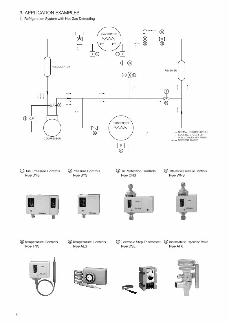
1). Refrigeration System with Hot Gas Defrosting
Dual Pressure Controls Type DYS
Pressure Controls Type SYS
Oil Protection Controls Type ONS
Differential Pressure Controls Type WNS
Temperature Controls Type TNS
Temperature Controls Type ALS
Electronic Step Thermostat Type DSE
Thermostatic Expansion Valve Type ATX
T T
P
O.P
D.P
COMPRESSOR
CONDENSER
EVAPORATOR
ACCUMULATORRECEIVER
S
S
S
NORMAL COOLING CYCLECOOLING CYCLE FORLOW CONDENSER TEMP.DEFROST CYCLE
3. APPLICATION EXAMPLES

2). Heat Pump System…Chiller
Thermostatic Expansion Valve Type RCX
Thermostatic Expansion Valve Type SCX
Thermostatic Expansion Valve Type BHX
Solenoid Valve Type REV…E
Solenoid Valve Type REV…B
4-Way Reversing Valve Type STF
Solenoid Valve Type VPV
Check Valve Type BCV
D.P
COMPRESSOR
L.P
INSIDE
RECEIVER
OUTSIDE
HEATEXCHANGER
HEATEXCHANGER
COOLING CYCLEHEATING CYCLE
TT
FAN
6

7
・Our products are listed by type number. In some types of products, not all models are listed.・Some approved items have special catalog number for the listing.・Some approved items require extra charges.・Please contact the company for details.
Standard for safety Standard for marine
APPROVAL STANDARD LIST
Type Number
CE
Pressure Controls Temperature Controls Solenoid Valves
ANS(W)(P), DNS(W)(P)
FNS(W)(P), HNS(W)
ONS(W), SNS(W)(P)
WNS(W), DYS, SYS
CFE, ETB, FTB, HTB
LTB, ACB, LCB, CCB
XSK, NSK, YNS
CNS(W)(P), INS(W)
TNS(W)(P) REV, WEV, RPV, STF
BPV, VPV, SEV, HPV
Flow Switchs Fan Speed Controllers
FQS RGE, XGE
UL
Pressure Controls Temperature Controls Solenoid Valves
DNS, HNS, SNS, WNS
ETB, FTB, HTB, LTB, SYS
ACB, XSK, NSK, DYS
CNS, TNS, EWS
FWS, LWS, RWSTEV, VPV, STF
Flow Switchs Electronic Expansion Valves Fan Speed Controllers
FQS
AKV, UKV, VKV RGE, XGEDrain Pumps
MDP
CQC
Pressure Controls Solenoid Valves Electronic Expansion Valves
DYS, SYS, ACB, LCB, NSKSNS, HNS, YNS, ONS, WNS RPV, STF, TEV-S UKV
Electric Proportional Valves Fan Speed Controllers Drain Pump
QJV RGE MDP, SDP
CSAPressure Controls Fan Speed Controllers
ETB, FTB, HTB, LTB, ACB, DNS, SNS RGE, XGE
IECEEPressure Controls
ETB, FTB, HTB, LTB, ACB, LCB, SNS, HNS, WNS, YNS, ONS, DYS, SYS
DINPressure Controls
ACB, DNS, SNS
VDE
Pressure Controls
ETB, FTB, HTB, LTB, ACB
Solenoid Valves
STF(01〜20, H01, H02)
Type Number
Pressure Controls Temperature Controls
LRANS, DNSFNS, HNS, ONSSNS, WNS, YNS
CNS, INS, TNS
DNV ∙ GLANS, DNSFNS, HNS, ONSSNS, WNS, YNS
CNS, INS, TNS
BVANS, DNSFNS, HNS, ONSSNS, WNS, YNS
CNS, INS, TNS
ABSANS, DNS, FNSHNS, ONS, SNSWNS, YNS
CNS, INS, TNS
NKANS, DNSFNS, HNS, ONSSNS, WNS, YNS
CNS, INS, TNS
International Protection StandardType Number International Protection
Pressure Controls
ONS, WNS, YNS, DYSSYS, ETB, FTB, HTB, LTB
IP20
ANS, FNS, HNSIP20(Standard type)IP44(When adding cover.)
ANS(W), DNS(W), FNS(W)HNS(W), ONS(W), SNS(W)WNS(W)
IP62
ANS(P), DNS(P), FNS(P)SNS(P), NSK(BH)
IP66
Temperature Controls ∙ Humidity Controls
EWS, FWS, LWS, RWSCNS, INS, TNS, ALS, BLSPWS, ARS, WRS, AHS
IP20
ALE, BLE IP44
CNS(W), INS(W), TNS(W) IP62
CNS(P), TNS(P), TNE IP66
*1 When using the mounting bracket, the degree of protection between the front of the product and the bracket.*2 Protection level is front of product.
・Basically, the IP protection level of this catalog is based on the measured value of JIS C 0920.
・The above IP protection grade is a general benchmark for the selected product.
・If you need a certificate issued by an external agency, please contact us.
*1
*2
Type Number International Protection
Pulse Converters
LNE IP20
Solenoid Valves
REV(W), UEV(W), WEV(W) IP34
RPV(DIN plug) IP65
RPV(Read wire) IP67
Damper & Valve Motor Actuators
EGK, WGK IP62
Flow Switchs
FQS(standard Type) IP20
FQS(Drip proof models) IP62
Fan Speed Controllers
RGE IP54
XGE IP65
Temperature Recorders
AKM IP20
LR (Lloyd's Register of Shipping)…EnglandDNV∙GL (Det Norske Veritas and Germanischer Lloyd)…
(Norway and Germany)BV (Bureau Veritas)…FranceABS (American Bureau of Shipping)…AmericaNK (Nippon Kaiji Kyokai)…Japan

PR
ES
SU
RE
CO
NT
RO
LS
SMALL PRESSURE CONTROLS・ ・・・・・・・・・・・・・・・9–10
Type ACB & LCB
SMALL PRESSURE CONTROLS・ ・・・・・・・・・・・・・・11–12
Type LTB, ETB, HTB & FTB
SINGLE FUNCTION PRESSURE CONTROLS・・・・・・13–14
Type SNS & HNS
DUAL PRESSURE CONTROLS・・・・・・・・・・・・・・・・・15–16
Type DNS
SINGLE FUNCTION PRESSURE CONTROLS・・・・・・・・ 17
Type SYS
DUAL PRESSURE CONTROLS・・・・・・・・・・・・・・・・・・・ 18
Type DYS
PRESSURE CONTROLS WITH NARROW DIFFERENTIAL・・・19–20
Type FNS & ANS
OIL PROTECTION CONTROLS・ ・・・・・・・・・・・・・・・21–22
Type ONS
DIFFERENTIAL PRESSURE CONTROLS・ ・・・・・・・・・・ 23
Type WNS & YNS
DIGITAL PRESSURE CONTROLS・・・・・・・・・・・・・・・・・ 24
Type CFE
PRESSURE SENSORS・・・・・・・・・・・・・・・・・・・・・・・25–27
Type NSK & XSK
PRESSURE CONTROLS

9
High Volume OEM Item
GENERAL DESCRIPTION
•PressureControlCBseriesaredisctypesmallpressurecontrols featuringcompact structure and fieldprovenhighquality.
•It isdesignedtosuitmoderndesignedapplicationwithitscompactandvarioustypeofconnectionstyles,suchapplication as air conditioning, automobile industriesandothers. TypeACB…High&mediumpressurerange TypeLCB…Lowpressurerange
SPECIFICATIONS
•Ambienttemperature:-30to100°C
Unit:MPakgf/cm2
SMALL PRESSURE CONTROLS (DISC TYPE)High Volume OEM Item
Type ACB & LCB
markapplicable(availableuponrequestforTypeACB&TypeLCB)
ULrecognized(availableuponrequestforTypeACB)
TypeACB,LCB
TypeACB,LCB
STANDARDTYPENUMBERSELECTIONTypeACB&LCB
CatalogNo. ContactFunctionsRange Max.
PressurePressure
Connections
TerminalConstruction(DIMENSION)
Application Wt.(kg)Off On
ACB
SPST (HighCut)
(A)
4.242 3.333
4.545
1/4"SolderOR
FemaleFlare
Open(①・③ )OR
WaterProof(②・④ )
HighPressureCutOut
Open(0.03)WaterProof
(0.06)
3.131 2.424
2.828 2.222
2.626 2.121
2.323 1.818
SPST(HighCut)+ManualReset
(B)
2.828 2.121
WaterProof(⑤ ) 0.062.626 2.020
2.323 1.818
SPDT(C)
2.828 2.222 Open(⑥ )OR
WaterProof(⑦ )
Open(0.03)WaterProof
(0.06)2.626 2.121
2.323 1.818
SPDT+ManualReset
(D)
2.828 2.121
WaterProof(⑧ ) 0.082.626 2.020
2.323 1.818
LCBSPST
(LowCut)(E)
0.222.2 0.363.6
1.515
Open(①・③ )OR
WaterProof(②・④ )
LowPressureCutOut
Open(0.03)WaterProof
(0.06)
0.171.7 0.272.7
0.070.7 0.171.7
0.050.5 0.151.5
ELECTRICAL RATINGSTypeACB&LCB
CategoryofRatings MRating LRating TRating
RatedVoltage(V)RatedCurrent(A)
PowerFactor(cosφ)
125V.AC 250V.AC 12V.DC 125V.AC 250V.AC 12V.DC 12/24V.DC
Non-InductiveCurrent 11to6 1to4
1to40.02to2 0.02to1
0.05to0.1 0.01to0.05
InductiveCurrent
FullLoad 0.75– – –
InrushCurrent – 1to24 1to16 0.02to8 0.02to4

10
CONTACT FUNCTIONSTypeACB&LCB
PRESSURE CONNECTIONS Unit:mm
H
L
C
RED
BLUE
BLACK
Code ECode A Code C Code D
H
LMM
C
RED
BLUE
BLACKH
C
Code B
High Press.Middle Press.
Low Press.
High Press.
Low Press.
HC C
SPST SPST/M SPSTSPDT SPDT/M
L
1/4" Female Flare 1/4" Male Flare Capillary 1/4" Copper Solder R 1/8"
713.5
φ4.2
710
φ10
L9.5
φ2.4×φ1×L(300mm)
3
φ5 I.D.
φ6.35
(φ8)
R 1/8"
+Schrader Depressor
Hex. 127/16 -20UNF7/16 -20UNF
① SPST ・ Female Flare ・ Open
② SPST ・ Female Flare ・ Water Proof
④ SPST ・ 1/4" Solder ・ Water Proof ⑧ SPDT ・ Manual Reset ・ Female Flare ・ Water Proof
⑦ SPDT ・ Female Flare ・ Water Proof
⑤ SPST ・ Manual Reset ・ Female Flare ・ Water Proof
③ SPST ・ 1/4" Solder ・ Open
⑥ SPDT ・ Female Flare ・ Open
16.4
Hex. 147/16 -20UNF
16.9 10.5
14φ21.7
(43.8)
16.4
39 30
(53.4) 15 104
13
L=1000
M4×0.7
16.4(50.4)
φ24
φ8
16.4 32 1000
φ24
L=1000
Hex. 147/16 -20UNF
Hex. 147/16 -20UNF
Hex. 147/16 -20UNF
16.9 10.5
14φ21.7
(85.6)58.23φ
6.35(φ8)
16.4 19.2 10.9
φ21.7
Hex. 147/16 -20UNF
(46.5)
358.2 33 1000
φ6.35
16.4
φ23.5
33
Hex. 147/16 -20UNF
1000
(φ8)
φ23.5
Reset Button
↑:Operatingdirectiononpress.increaseatHighPress.SideM↓:Operatingdirectiononmanualreset
DIMENSIONS Unit:mm

11
GENERAL DESCRIPTION•Factorysetpressureswitchdesignedforuseinrefriger-ation units of quantity production such as roomairconditioner(heatpump),packagedairconditioner(heatpump),waterchilleretc.
•WithSPDTcontactmechanism.•Models identifiedwith electrical rating codeL canbeusedforminimum0.02A/125V.ACrating.
•Modelswith0.78 to1.96MPa 8 to20kgf/cm2 rangearealsoavailableforHTBandFTB.
•Modelswith0.098MPa1kgf/cm2differentialarealsoavailable forHTB (max. range limit: 1.27MPa 13 kgf/ cm2).
TypeHTB
TypeFTB
SMALL PRESSURE CONTROLSHigh Volume OEM Item
Type LTB, ETB, HTB & FTB
markapplicable(availableuponrequest)
ULrecognized(availableuponrequest)
High Volume OEM Item
ELECTRICAL RATINGSRatedVoltage(V)
RatedCurrent(A)Terminal
PowerFactor(cosφ)
HRating MRating LRating
125V.AC 250V.AC 125V.AC 250V.AC 125V.AC 250V.AC
Non-InductiveCurrent
C–L
1 1to10 1to10 1to3 0.5to1.50.02to2 0.02to1
InductiveCurrent
FullLoad 0.75 1to6 1to6 1to2 0.5to1
InrushCurrent – 1to24 1to241to8
0.5to4 0.02to8 0.02to4
Non-InductiveCurrent
C–H
11to16 1to16
0.5to50.02to2 0.02to1
InductiveCurrent
FullLoad 0.75 1to6 0.5to4
InrushCurrent – 1to64 1to64 1to24 0.5to16 0.02to8 0.02to4
TYPENUMBERSELECTION Unit:MPakgf/cm2
* RefertoElectricalRatingsTableinthelistbelow.
CatalogNo. ApplicationRange
DifferentialFactorySetting Max.
WorkingPressure
PressureConnections
ElectricalRatings
Wt.(kg)Min. Max. On Off
LTB–A301
LowPressure
0 0.3924
0.059to0.1470.6to1.5
0.2943
0.1962
1.515
H
0.08
LTB–A302 M
LTB–A303 L
LTB–A304
H
LTB–A305 M
LTB–A306 L
ETB–A301
0.0981
0.2452.5
Automaticoperationonpressure
decreaseandmanualresetonpressureincrease
ManualReset
0.0981
H
0.1
ETB–A302 M
ETB–A303 L
ETB–A304
H
ETB–A305 M
ETB–A306 L
HTB–A301
HighPressure
0.788
1.9620
0.29to0.493to5
1.9620
2.4525
3.333
H
0.09
HTB–A302 M
HTB–A303 L
HTB–A3041.9620
2.9430
0.29to0.693to7
H
HTB–A305 M
HTB–A306 L
FTB–A301
0.788
2.9430
Automaticoperationonpressure
increaseandmanualresetonpressuredecrease
ManualReset
H
0.1
FTB–A302 M
FTB–A303 L
FTB–A304
H
FTB–A305 M
FTB–A306 L
*
SPECIFICATIONS•Fluidtemperature:-20to120°C•Ambienttemperature:-20to70°C

12
CONTACT FUNCTIONS
PRESSURE CONNECTIONS
DIMENSIONS
・1/4"SolderConnectionisalsoavailableuponrequest.
CH
LC
H
L
M2C
H
LM1
TypeLTB&HTB TypeETB(M2:ManualReset) TypeFTB(M1:ManualReset)
φ2.4×1000Capillary Tube
φ2.4×1000Capillary Tube
Dust Protection Cap1/4" Flare Nut
68
36
36
2-M4×0.7
2-M4×0.7
18 24.5
18 26Max. 47
Max. 50
55
55
18 2618 26
13.9
13.5
Max. 50
Max. 50
55
55
Faston Terminal3-#250
Faston Terminal3-#250
φ2.4×1000
φ2.4×1000
64.536
64.536
2-M4×0.7
2-M4×0.7
φ8 Reset Button
Faston Terminal3-#250
Faston Terminal3-#250
φ2.4×1000
φ2.4×1000
64.5
TypeLTB TypeETB
TypeHTB TypeFTB
↑:Operatingdirectiononpress.increaseatHighPress.SideM1↓,M2↑:Operatingdirectiononmanualreset
Unit:mm
C CommonTerminal
L CloseonPressureIncrease
H CloseonPressureDecrease

13
SINGLE FUNCTION PRESSURE CONTROLS Type SNS & HNS
GENERAL DESCRIPTION
•Forusewith fluorinated refrigerantsaswell aswithairandwater.(Allowablefluidtemp.:−20to120°C)
•TypeSNSforuniversalapplication.•TypeHNSforhighpressuresafetycutout.•Availabledripproofenclosure formarineapplicationorexplosionproofenclosureforspecialapplication.
•Mountingbracketissuppliedasstandard.•WithSPDTcontactmechanism.•IP44withupperlid(option).•Stainlesssteelmodelsareavailableuponrequest.
CatalogNo.Range
ManualResetFactorySetting Max.Working
PressureContactFunction
Wt.(kg)Min. Max. Off On
HNS–C130XM1 0.8 8
3 30
Automaticoperationonpressureincrease,and
manualresetonpressuredecrease※2
2 20
ManualReset
3.333 Diagram4 0.24
* Basedonthe1–3terminalconnection.・ Enciosure:IP20・ DripProofModels:Availableuponrequest. (Refertopage48,49,50,51.)
TypeHNS–Manualresettype Unit:MPakgf/cm2
markapplicable(availableuponrequest)
ULrecognized(availableuponrequest)
Type SNS
Type HNS
CatalogNo.Range Differential FactorySetting Max.Working
PressureContactFunction
Wt.(kg)Min. Max. Min. Max. Off(On) On(Off)
SNS–C101X −0.06−50cmHg 0.11 0.0150.15 0.05 0.50.0250.25 0.05 0.5
0.33
Diagram1 0.33
SNS–C102X −0.02−20cmHg 0.22 0.0250.25 0.15 1.5 0.55
SNS–C103X −0.06−50cmHg 0.33 0.0350.350.22
0.05 0.5 0.15 1.5 110
SNS–C104X −0.06−50cmHg 0.44 0.040.4 0.11 0.22
1.515SNS–C106X −0.06−50cmHg 0.66 0.060.6 0.44 0.22 0.33
SNS–C110X 0.11 110 0.11 0.33 0.44 0.66
SNS–C120X0.55
220 0.22 0.55 1.212 1.515 330
SNS–C130X 330 0.33 110 220 2.525 3.333
SNS–C135X 110 3.535 0.55 1.515 2.525 330 3.838
TYPENUMBERSELECTIONTypeSNS–Automaticresettype Unit:MPakgf/cm2
CatalogNo.Range
ManualResetFactorySetting Max.Working
PressureContactFunction
Wt.(kg)Min. Max. Off On
SNS–C102XM2 −0.02−20cmHg 0.22 Automaticoperationonpressuredecreasse,andmanualresetonpressure
increase※1
0.0250.25ManualReset
0.55
Diagram2 0.33SNS–C106XM2 −0.06−50cmHg 0.66 0.22 1.515
SNS–C130XM2 0.55 330 220 3.333
* Basedonthe1–3terminalconnection.
TypeSNS–Manualresettype Unit:MPakgf/cm2*
CatalogNo.Range Differential FactorySetting Max.Working
PressureContactFunction
Wt.(kg)Min. Max. Fixed Off On
HNS–C130X 0.8 8
3 30
0.3to0.53to5
2 20
1.6 16
3.333 Diagram3 0.24
TypeHNS–Automaticresetrype Unit:MPakgf/cm2
* Basedonthe1–3terminalconnection.
SPECIFICATIONS
•Fluidtemperature:−20to120°C•Ambienttemperature:−20to70°C
※1 Pleasepresstheresetbuttonafterthepressureincreasedatspecifiedpoint. PressureRange:02...about0.04MPa 06...about0.1MPa 30...about0.5MPa※2 Pleasepresstheresetbuttonafterthepressuredecreasedabout0.7MPaorless.
*
*

14
ELECTRICAL RATINGS
PRESSURE CONNECTIONS
1/4" Flare7/16-20 Thread
1/4"Flare Nut
φ2.4×1000Capillary Tube
CONTACT FUNCTIONS
15
31
5
3
13
51
3
5M1
M2
(59)
(19) (17.4)
φ22
9.4
63.1
(91)
φ6(1/4")Flare Nut
Reset Button
(54)(48.8)
33.4
4-M4×0.7Thread MountingHole for Bracket
(20.8)
25±0.5
(17.3)
RangeAdjusting Screw
Standard
Diagram1 Diagram2
DIMENSIONSStandard
↑:Operatingdirectiononpress.increaseatHighPress.Side M1↓,・M2↑:OperatingdirectiononmanualresetRefertopage45,46.
Unit:mm
RatedVoltage(V)RatedCurrent(A)
PowerFactor(cosφ) 125/250V.AC
Non-InductiveCurrent 112
InductiveCurrentFullLoad 0.75
InrushCurrent – 72
Diagram1&2 Diagram3&4
1 CommonTerminal CommonTerminal
3 OpenonPressureIncrease OpenonPressureIncrease
5 OpenonPressureDecrease OpenonPressureDecrease
CatalogNo.Unit:mm
A B
SNS–C101X 113.3
22.4
SNS–C102X99.7
SNS–C103X
SNS–C104X
96.8SNS–C106X
SNS–C110X
SNS–C120X 95.9
18.4SNS–C130X93.5
SNS–C135X
SNS–C102XM2 99.722.4
SNS–C106XM2 96.8
SNS–C130XM2 93.5 18.4
Diagram3 Diagram4
Type HNS
Type SNS4‐M4×0.7Thread MountingHole for Bracket
(54)(50)36.422.4
(20.8)
25±0.5
(17.3)
Reset Button(9.4)
63.1
(A)
(B)
80
Differential Adjusting Screw
Range Adjusting Screw
φ6(1/4")Flare Nut
20.5

15
DUAL PRESSURE CONTROLS Type DNS
GENERAL DESCRIPTION
•Forusewith fluorinated refrigerantsaswell aswithairandwater.(AllowableFluidTemp.:− 20to120°C)
•Variouscontactfunctionsareavailable.•Availabledripproofenclosure formarineapplicationorexplosionproofenclosureforspecialapplication.
•Mountingbracketissuppliedasstandard.•IP44withupperlid(option).•Stainlesssteelmodelsareavailableuponrequest.
markapplicable(availableuponrequest)
ULrecognized(availableuponrequest)
TYPENUMBERSELECTIONAutomaticresettype Unit:MPakgf/cm2
CatalogNo. PressureSide
Range Differential FactorySetting Max.WorkingPressure
ContactFunction
Wt.(kg)Min. Max. Min. Max. Off On
DNS–D304XLowSide −0.06−50cmHg 0.44 0.040.4 0.22 0.11 0.22 1.515
Diagram1
0.49
HighSide 0.88 330 Approx.0.4fixedApprox.4fixed 220 1.616 3.333
DNS–D306XLowSide −0.06−50cmHg 0.66 0.060.6 0.44 0.22 0.33 1.515
HighSide 0.8 8 330 Approx.0.4fixedApprox.4fixed 220 1.616 3.333
DNS–D604XLowSide −0.06−50cmHg 0.44 0.040.4 0.22 0.11 0.22 1.515
Diagram3HighSide 0.8 8 330 Approx.0.4fixedApprox.4fixed 220 1.616 3.333
DNS–D606XLowSide −0.06−50cmHg 0.66 0.060.6 0.44 0.22 0.33 1.515
HighSide 0.88 330 Approx.0.4fixedApprox.4fixed 220 1.616 3.333
Manualresettype
・・Enclosure:IP20・・DripProofModels:Availableuponrequest. (RefertoPages49,50.)
※1 Pleasepresstheresetbuttonafterthepressureincreasedabout0.1MPaormore.
※2 Pleasepresstheresetbuttonafterthepressuredecreasedabout0.7MPaorless.
CatalogNo. PressureSide
Range Differential FactorySetting Max.WorkingPressure
ContactFunction
Wt.(kg)Min. Max. Min. Max. Off On
DNS–D304XM
LowSide -0.06-50cmHg 0.44 0.040.4 0.22 0.11 0.22 1.515
Diagram2
0.49
HighSide 0.88 330Automaticoperationonpressureincrease,andmanualreseton
pressuredecrease※2220 manual
reset 3.333
DNS–D306XM
LowSide -0.06-50cmHg 0.66 0.060.6 0.44 0.22 0.33 1.515
HighSide 0.88 330Automaticoperationonpressureincrease,andmanualreseton
pressuredecrease※2220 manual
reset 3.333
DNS–D604XM
LowSide -0.06-50cmHg 0.44 0.040.4 0.22 0.11 0.22 1.515
Diagram4
HighSide 0.88 330Automaticoperationonpressureincrease,andmanualreseton
pressuredecrease※2220 manual
reset 3.333
DNS–D606XM
LowSide -0.06-50cmHg 0.66 0.060.6 0.44 0.22 0.33 1.515
HighSide 0.88 330Automaticoperationonpressureincrease,andmanualreseton
pressuredecrease※2220
manualreset
3.333
DNS–D606XMM
LowSide -0.06-50cmHg 0.66Automaticoperationonpressuredecrease,andmanualreseton
pressureincrease ※10.22 1.515
Diagram5
HighSide 0.88 330Automaticoperationonpressureincrease,andmanualreseton
pressuredecrease※2220 3.333
Unit:MPakgf/cm2
SPECIFICATIONS
•Fluidtemperature:-20to120°C•Ambienttemperature:-20to70°C

16
CONTACT FUNCTIONS
1
4
H2
L
3 1
4
H
M
2
L
3
1
45
62 H
L
3 1
45
62 H
ML
3 1
45
62 H
MLM
3 ↑ L:Operatingdirectiononpress.increaseatLowPress.Side↑ H:Operatingdirectiononpress.increaseatHighPress.Side↓M:Operatingdirectiononmanualreset
PRESSURE CONNECTIONS
DIMENSIONSStandardModel
φ6(1/4")Flare Nut
20.5 20.5
Reset Button
(17.4)(22.4)
4‐M4×0.7Thread MountingHole for Bracket
(20.8)
25±0.5
(17.3)
(54)(50)
36.422.4
(9.4)
63.1
(96.8)
φ22
63(24)
(106)
High Range Adjusting Screw
Low Range Adjusting Screw
φ34.4
Low Range Differential Adjusting Screw
1/4"Flare Nut
φ2.4x1000Capillary Tube1/4" Flare
7/16-20 Thread
Diagram1 Diagram2
Diagram3 Diagram4 Diagram5
Standard
Unit:mm
RefertoPages45,46
ELECTRICAL RATINGSRatedVoltage(V)
RatedCurrent(A)PowerFactor
(cosφ) 125/250V.AC
Non-InductiveCurrent 112
InductiveCurrentFullLoad 0.75
InrushCurrent – 72
Minimumcontactcapacity:50mA

17
SINGLE FUNCTION PRESSURE CONTROLS Type SYS
GENERAL DESCRIPTION•TypeSYSisstandardmodel.Reliableperformance,andlonglifeproducts.
•ApplicableforR410A(SYS–C140X0)•Scaleplatewithsignificantlyclearvisibility•Compactandlightweight
markapplicable(availableuponrequest)
Manualresettype Unit:MPakgf/cm2
・・Enclosure:IP20*1・ StandardunitdisplayisMPa.Otherunitdisplaysareavailableuponrequestbychanging“X0”portionofacatalognumber. [X0:MPa,X1:bar,X2:kgf/cm2,X3:kPa,X4:lb/in2,X5:psi]
*2 TheproductsotherthanSYS–C140X0arenotcompatiblewithR410Arefrigerant.
*3 Indicatestheaveragevaluealsoconsideringinstrumentalerrors.
CatalogNo. RefrigerantRange
ManualResetFactorySetting Max.Working
PressureContactFunction
Wt.(kg)Min. Max. Off(On) On(Off)
SYS–C106X0M2 R404A,R407CR134a,R22
-0.06-50cmHg 0.66 Automaticoperationonpressuredecreaseandmanualresetonpressureincrease
0.22 ManualReset
1.6516.5 Diagram2 0.25
SYS–C130X0M2 0.55 330 1.515 3.333
*1 *2
TYPENUMBERSELECTIONAutomaticresettype Unit:MPakgf/cm2
CatalogNo. RefrigerantRange Differential FactorySetting Max.Working
PressureContactFunction
Wt.(kg)Min. Max. Min. Max. Off(On) On(Off)
SYS–C103X0
R404A,R407CR134a,R22
-0.06-50cmHg0.33 0.0350.35 0.22 0.050.5 0.151.5
1.6516.5
Diagram1 0.25
SYS–C106X0 0.66 0.060.6 0.44 0.22 0.33
SYS–C110X0 0.11 110 0.11 0.33 0.44 0.66
SYS–C130X0 0.55 330 0.33 110 1.515 220 3.333
SYS–C135X0110
3.5350.55
1.515220 2.525
3.838
SYS–C140X0 R410Aetc. 4.343 110 4.747
*1 *2
*3
DIMENSIONS
7/16-20UNF(18)
AUTO RESET
(48)
(75)
A
25±0.5 31.1
25±0.5
(65.5)
(86.5)
21.4
4-M4×0.7Thread Mounting Hole for Bracket
RangeAdjusting Screw
Differential Adjusting Screw Reset Button
Unit:mm
ELECTRICAL RATINGS CONTACT FUNCTIONS
15
31
5
3
13
51
3
5M1
M2
Diagram1 Diagram2↑:Operatingdirectiononpress. increaseatHighPress.SideM2↑:Operatingdirectionon manualreset
RatedVoltage(V)RatedCurrent(A)
PowerFactor(cosφ) 125/250V.AC
Non-InductiveCurrent 112
InductiveCurrent
FullLoad 0.75
InrushCurrent – 72
Diagram1&2
1 CommonTerminal
3 CloseonPressureIncrease
5 CloseonPressureDecrease
Minimumcontactcapacity:50mA
CatalogNo.Unit:mm
A
SYS–C103 to 110 17.7
SYS–C130 to 140 16.7
SPECIFICATIONS•Fluidtemperature:-20to120°C•Ambienttemperature:-20to70°C

18
AUTO RESET
7/16-20UNF74.2
(65.5)
(86.5)
(86.5)
(110)
(17.9)
(48)
25±0.5
15.9
17.7
25±0.5
4-M4×0.7Thread Mounting Hole for Bracket
40.4
20.3
Low Range Adjusting Screw
Low Range Differential Adjusting Screw
High Range Adjusting Screw
High Press. Side Reset ButtonLow Press. Side Reset Button
DIMENSIONS
DUAL PRESSURE CONTROLS Type DYS
GENERAL DESCRIPTION•TypeDYS isdual pressure controls that is integratedwithoverpressureprotectionof thehighpressuresideandcontroloflowpressuresideoftherefrigerationunit.
•Scaleplatewithsignificantlyclearvisibility•Compactandlightweight
markapplicable(availableuponrequest)
TYPENUMBERSELECTIONAutomaticresettype Unit:MPakgf/cm2
CatalogNo. PressureSide
Range Differential FactorySetting Max.WorkingPressure
ContactFunction
Wt.(kg)Min. Max. Min. Max. Off On
DYS–D306X0LowSide -0.06-50cmHg 0.66 0.060.6 0.44 0.22 0.33 1.6516.5
Diagram1
0.40HighSide 0.88 330 Approx.0.5fixed.Approx.5fixed. 220 1.515 3.333
DYS–D606X0LowSide -0.06-50cmHg 0.66 0.060.6 0.44 0.22 0.33 1.6516.5
Diagram3HighSide 0.88 330 Approx.0.5fixed.Approx.5fixed. 220 1.515 3.333
*1
*2
Manualresettype Unit:MPakgf/cm2
・・Enclosure:IP20*1・ StandardunitdisplayisMPa.Otherunitdisplaysareavailableuponrequestbychanging“X0”portionofacatalognumber. [X0:MPa,X1:bar,X2:kgf/cm2,X3:kPa,X4:lb/in2,X5:psi]
*2 Indicatestheaveragevaluealsoconsideringinstrumentalerrors.
CatalogNo. PressureSide
Range Differential FactorySetting Max.WorkingPressure
ContactFunction
Wt.(kg)Min. Max. Min. Max. Off On
DYS–D306X0M
LowSide -0.06-50cmHg 0.66 0.060.6 0.44 0.22 0.33 1.6516.5
Diagram2
0.40
HighSide 0.88 330Automaticoperationonpressureincreaseandmanualreseton
pressuredecrease220 manual
reset 3.333
DYS–D606X0M
LowSide -0.06-50cmHg 0.66 0.060.6 0.44 0.22 0.33 1.6516.5
Diagram4HighSide 0.88 330
Automaticoperationonpressureincreaseandmanualreseton
pressuredecrease220
manualreset
3.333
DYS–D606X0MM
LowSide -0.06-50cmHg 0.66Automaticoperationonpressuredecreaseandmanualreseton
pressureincrease0.22 1.6516.5
Diagram5
HighSide 0.88 330Automaticoperationonpressureincreaseandmanualreseton
pressuredecrease220 3.333
*1
*2
Unit:mm
ELECTRICAL RATINGSRatedVoltage(V)
RatedCurrent(A)PowerFactor
(cosφ)125/250V.
AC
Non-InductiveCurrent 112
InductiveCurrentFullLoad 0.75
InrushCurrent – 72
Minimumcontactcapacity:50mA
CONTACT FUNCTIONSRefertoPages16
SPECIFICATIONS•Fluidtemperature:-20to120°C•Ambienttemperature:-20to70°C

19
PRESSURE CONTROLS WITH NARROW DIFFERENTIAL Type FNS & ANS
GENERAL DESCRIPTION
•Forusewith fluorinated refrigerantsaswell aswithairandwater.
•TypeFNSwithfixednarrowdifferential•TypeANSwithadjustablenarrowdifferential•Availabledripproofenclosure formarineapplicationorexplosionproofenclosureforspecialapplication.
•Mountingbracketissuppliedasstandard.•WithSPDTcontactmechanism.•IP44withupperlid(option).……Type FNS•Stainlesssteelmodelsareavailableuponrequest.
TYPENUMBERSELECTIONTypeFNS–Fixednarrowdifferentialtype
Type ANS – Adjustablenarrowdifferentialtype
・・Enclosure:IP20 ・・DripProofModels:Availableuponrequest.(Refertopage51.)
Unit:MPakgf/cm2
Unit:MPakgf/cm2
markapplicable(availableuponrequest)Type FNS
Type ANS
CatalogNo.Range
DifferentialFactorySetting Max.Working
PressureWt.(kg)Min. Max.
Min. Max. Bottom Top Bottom Top Off On
ANS–C101XB -0.06 -50cmHg
0.11
0.0070.07
0.0070.07
0.0140.14
0.0150.15
0.0180.18
0.0250.25
0.33
0.32
ANS–C103XB -0.02 -20cmHg
0.33
0.0080.08
0.010.1
0.0180.18
0.0270.27
0.1411.41
0.151.5
110
ANS–C106XB -0.06 -50cmHg
0.66
0.0150.15
0.0180.18
0.030.3
0.0450.45
0.282.84
0.33.0 1.5
15ANS–C110XB 0.1
11
100.020.2
0.030.3
0.0450.45
0.070.7
0.5755.75
0.66.0
ANS–C130XB 0.55
330 0.12
1.20.22.0
0.232.3
0.373.7
2.3223.2
2.525
3.333
ANS–C135XB 110
3.535
0.242.4
0.393.9
2.8228.2
330
3.838
CatalogNo.Range Differential FactorySetting Max.Working
PressureWt.(kg)Min. Max. Fixed Off On
FNS–C101X -0.06 -50cmHg
0.11
0.006Approx. 0.06Approx.
(0.019)(0.19)
0.0250.25
0.33
0.32
FNS–C102X -0.02 -20cmHg
0.22
0.008Approx. 0.08Approx.
(0.042)(0.42)
0.050.5
0.55
FNS–C106X -0.06 -50cmHg
0.66
0.02Approx. 0.2Approx.
(0.28)(2.8)
0.33.0 1.5
15FNS–C110X 0.1
11
100.025Approx. 0.25Approx.
(0.575)(5.75)
0.66.0
FNS–C130X 0.55
330
0.12Approx. 1.2Approx.
(2.38)(23.8)
2.525
3.333
SPECIFICATIONS
•Fluidtemperature:-20to120°C•Ambienttemperature:-20to70°C

20
CONTACT FUNCTIONS
15
3
↑:Operatingdirectiononpress.increaseatHighPress.Side
PRESSURE CONNECTIONS
1/4" Flare
DIMENSIONSStandardModel
Type ANS
MP1.5MPa
-0.06
0
0.2
0.4
0.6
RANGE
4-M4×0.7Thread MountingHole for Bracket
(50)22.4
(20.8)
25±0.5
(17.3)
63.1
(A)
(B)
80
20.5
MPa
RangeAdjusting Screw
φ6(1/4")Flare Nut
MP1.5MPa
-0.06
0
0.2
0.4
0.6
RANGE
4-M4×0.7Thread MountingHole for Bracket
(50)
8
22.4
(20.8)
25±0.5
(17.3)
63.1
(A)
(B)
80
20.5
φ21
MPa
RangeAdjusting Dial
φ6(1/4")Flare Nut
ELECTRICAL RATINGS
Unit:mm
Type FNS
Refertopage45,46.Standard
CatalogNo.Unit:mm
A B
FNS–C101X 113.3
22.4FNS–C102X 99.7
FNS–C106X96.8
FNS–C110X
FNS–C130X 93.5 18.4
CatalogNo.Unit:mm
A B
ANS–C101XB 113.3
22.4ANS–C103XB 99.7
ANS–C106XB96.8
ANS–C110XB
ANS–C130XB93.5 18.4
ANS–C135XB
RatedVoltage(V)RatedCurrent(A)
PowerFactor(cosφ) 125/250V.AC
Non-InductiveCurrent 112
InductiveCurrentFullLoad 0.75
InrushCurrent – 72
1 CommonTerminal
3 CloseonPressureIncrease
5 CloseonPressureDecrease

21
GENERAL DESCRIPTION
•Providesdependableprotection againstmajorbreak-downonpressure lubricated refrigeration compressorsbyguardingagainstlowlubricationoilpressure.
•Withmanualreset.•Builtintimedelayswitch.•Mountingbracketissuppliedasstandard.•Stainlesssteelmodelsareavailableuponrequest.
TYPENUMBERSELECTION Unit:MPakgf/cm2
・・Max.WorkingPressure:1.5MPa15kgf/cm2・・・LimitofPressureDiff.Hp≧Lp:1.5MPa15kgf/cm2,Hprepresents
oilpumpdischargepressureandLpcrankcasepressure.
・・Enclosure:・IP20・・DripProofModels:Availableuponrequest.(Refertopage52.)
※After・the・timer・operation,・please・press・the・reset・button・later・30・minutes.
OIL PROTECTION CONTROLS Type ONS
markapplicable(availableuponrequest)
CatalogNo.Range Differential TimerSpecification
Connection Wt.(kg)Min. Max. Fixed DelayTime(sec.) TimerVoltage TimerCircuit
ONS–C106XQ1
0.050.5
0.353.5
Approx.0.05
Approx.0.5
45100/200V.AC
Standard(SPST)withoutAlarmContact
1/4"FlareNut 0.55
ONS–C106XQ2 90ONS–C106XQ3 110ONS–C106XQ4 45
110/220V.ACONS–C106XQ5 90ONS–C106XQ6 110ONS–C106XQ7 45
115/230V.ACONS–C106XQ8 90ONS–C106XQ9 110ONS–C106XQ10 45
120/240V.ACONS–C106XQ11 90ONS–C106XQ12 110ONS–C106XL1Q1 45
100/200V.AC
1000mmCapil.Tubewith1/4"
FlareNut0.62
ONS–C106XL1Q2 90ONS–C106XL1Q3 110ONS–C106XL1Q4 45
110/220V.ACONS–C106XL1Q5 90ONS–C106XL1Q6 110ONS–C106XL1Q7 45
115/230V.ACONS–C106XL1Q8 90ONS–C106XL1Q9 110ONS–C106XL1Q10 45
120/240V.ACONS–C106XL1Q11 90ONS–C106XL1Q12 110ONS–C106XQ25 45
100/200V.AC
WithAlarmContact(SPDT)
1/4"FlareNut 0.55
ONS–C106XQ26 90ONS–C106XQ27 110ONS–C106XQ28 45
110/220V.ACONS–C106XQ29 90ONS–C106XQ30 110ONS–C106XQ31 45
115/230V.ACONS–C106XQ32 90ONS–C106XQ33 110ONS–C106XQ34 45
120/240V.ACONS–C106XQ35 90ONS–C106XQ36 110ONS–C106XL1Q25 45
100/200V.AC
1000mmCapil.Tubewith1/4"
FlareNut0.62
ONS–C106XL1Q26 90ONS–C106XL1Q27 110ONS–C106XL1Q28 45
110/220V.ACONS–C106XL1Q29 90ONS–C106XL1Q30 110ONS–C106XL1Q31 45
115/230V.ACONS–C106XL1Q32 90ONS–C106XL1Q33 110ONS–C106XL1Q34 45
120/240V.ACONS–C106XL1Q35 90ONS–C106XL1Q36 110
SPECIFICATIONS
•Fluidtemperature:-20to120°C•Ambienttemperature:-20to70°C

22
ELECTRICAL RATINGS
CONTACT FUNCTIONS
・・・・↑:Operatingdirectionofpressureincrease・・・・c:OperatingdirectionoftimerwhenenergizedM↓:Operatingdirectionofmanualreset
1
100V
L2 L1
L3MMotor Circuit
Heater
Heater Circuit
200V
110/220V.AC,120/240V.ACetc.available
PRESSURE CONNECTIONS
DIMENSIONS
1/4" Flare7/16-20 Thread
1/4"Flare Nut
φ2.4×1000Capillary Tube
Standard
MP
1.5MPa
0.1 0.2 0.3 0.35
RANGE
H P
MPa
(20.5)
20.5 (20.5)
(116)
18.9
62.8(141.2)
(17.3)
(22.4) (49.1)
(51)
25±0.5
(13)
φ34.4
4-M4×0.7Thread Mounting Hole for Bracket
φ6(1/4") Flare NutReset Button
Lead wire for Alarm Contact
Unit:mm
Refertopage45,46. (L3:AlarmContactprovidedwithaleadwireapprox.) φ3.5×100mmwithasolderedterminal.
RatedVoltage(V)RatedCurrent(A)
PowerFactor(cosφ) 125/250V.AC
Non-InductiveCurrent 1 3.5
InductiveCurrentFullLoad 0.75 3
InrushCurrent – 10
1
HeaterCircuit
CommonTerminal
100 100VPowerSupplyTerminal
200 200VPowerSupplyTerminal
L1
MotorCircuit
OpenonDecreaseofPressureDifference
L2 MainContact
L3 AlarmContact

23
GENERAL DESCRIPTION
Type WNS•Differentialpressureisadjustablecontroller.•Itissuitableforwatercuttoffdetectionofcoolingwatercircuit.•StandardType:IP20Type YNS •Narrowdifferntialpressure(fixed)controller.•StandardType:IP20
PRESSURE CONNECTIONS
DIMENSIONS
1/4" Flare7/16-20 Thread
MP
1.5MPa
0.25
0.2 0.15
0.1
0.05
0.1 0.2 0.35
RANGE
DIFF.
20.563.1
20.5(B)
(D)(C)
(24)
(80)
(20.8)
(22.4)(50)
25±0.5 (17.3)
φA
H P
MPa
4-M4×0.7Thread MountingHole for Bracket
φ6(1/4") Flare Nut
Standard
DIFFERENTIAL PRESSURE CONTROLS Type WNS & YNS
Unit:mm
markapplicable(availableuponrequest) ULrecognized(availableuponrequest)
Refertopage45,46.
TYPENUMBERSELECTIONTypeWNS–Adjustabledifferentialtypeforwater,airandfluorinatedrefrigerant Unit:MPakgf/cm2
CatalogNo.Range Differential FactorySetting Max.Working
Pressure
LimitofPress.Differential
(HP> LP)
Wt.(kg)Min. Max. Min. Max Off On
WNS–C102X 0.030.3 0.22 0.030.3 0.151.5 0.050.5 0.020.2 0.55 0.550.43
WNS–C106X 0.050.5 0.353.5 0.050.5 0.252.5 0.11.0 0.050.5 1.515 1.515
ELECTRICAL RATINGS
CONTACT FUNCTIONS
15
3
↑:Operatingdirectiononpress.increaseatHighPress.Side
RatedVoltage(V)RatedCurrent(A)
PowerFactor(cosφ) 125/250V.AC
Non-InductiveCurrent 112
InductiveCurrentFullLoad 0.75
InrushCurrent – 72
1 CommonTerminal
3 CloseonPressureIncrease
5 CloseonPressureDecrease
CatalogNo.Unit:mm
φA B C D
WNS–C102X 38.5 50.0 39.0 147.2
WNS–C106X 34.4 47.0 36.0 141.2
SPECIFICATIONS
•Fluidtemperature:-20to120°C•Ambienttemperature:-20to70°C•Forwater,airandfluorinatedrefrigerant
・・HP......HighSidePress.LP......LowSidePress.・Enclosure:・IP20・・Dripproofmodels:Availableuponrequest.(Refertopage52.)・Pleasecontactusifotherrangemodelsarerequired.
TypeYNS–Fixednarrowdifferential
CatalogNo.Range Differential FactorySetting Max.Working
Pressure
LimitofPress.Differential
(HP> LP)
Wt.(kg)Min. Max. Fixed Off On
YNS–C102X 0.020.2 0.22 0.0150.15approx. 0.050.5 (0.035)(0.35) 0.55 0.550.43
YNS–C106X 0.0250.25 0.353.5 0.0250.25approx. 0.151.5 (0.125)(1.25) 1.515 1.515
Unit:MPakgf/cm2
24
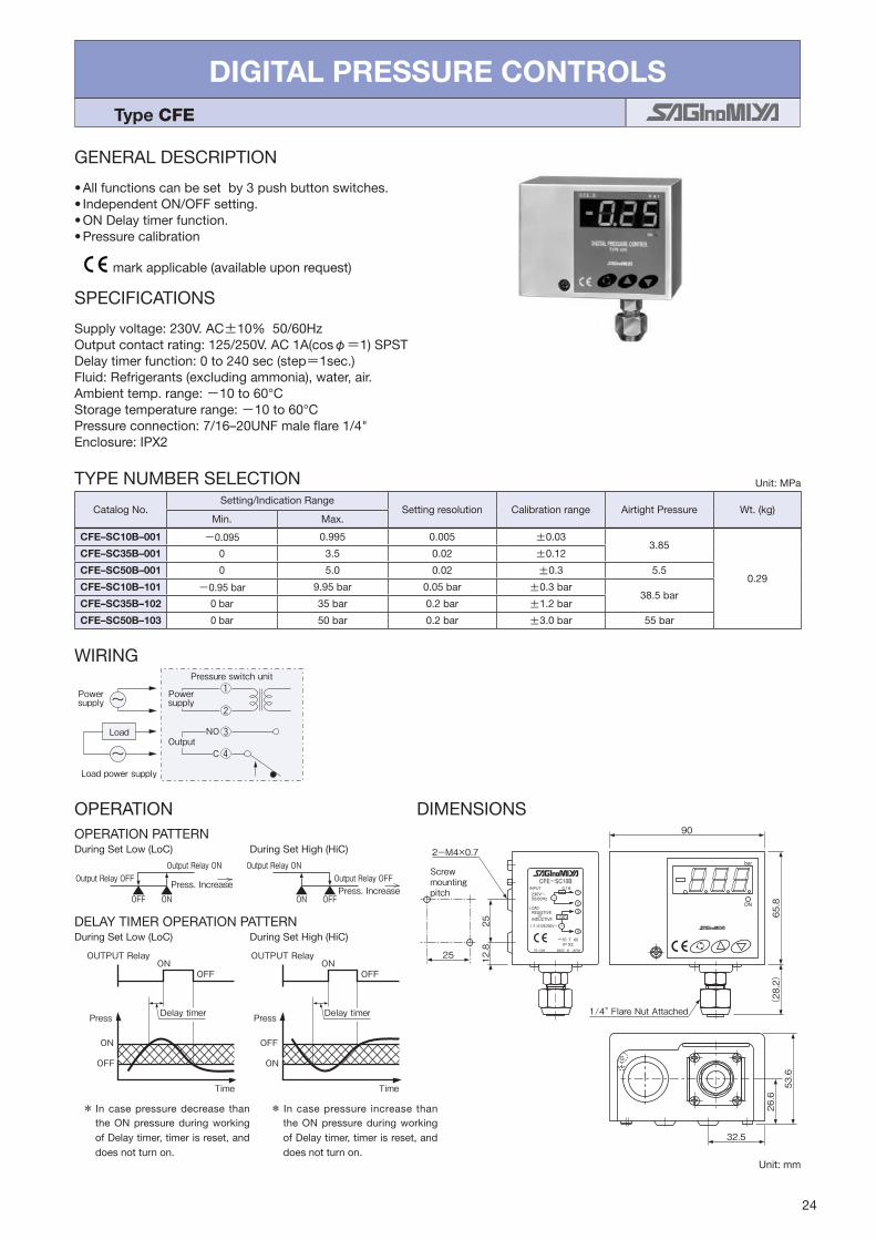
GENERAL DESCRIPTION
•Allfunctionscanbesetby3pushbuttonswitches.•IndependentON/OFFsetting.•ONDelaytimerfunction.•Pressurecalibration
SPECIFICATIONS
Supplyvoltage:230V.AC±10%50/60HzOutputcontactrating:125/250V.AC1A(cosφ=1)SPSTDelaytimerfunction:0to240sec(step=1sec.)Fluid:Refrigerants(excludingammonia),water,air.Ambienttemp.range:-10to60°CStoragetemperaturerange:-10to60°CPressureconnection:7/16–20UNFmaleflare1/4"Enclosure:IPX2
* In casepressuredecrease thantheONpressureduringworkingofDelaytimer,timerisreset,anddoesnotturnon.
* In casepressure increase thantheONpressureduringworkingofDelaytimer,timerisreset,anddoesnotturnon.
OPERATIONOPERATION PATTERN
DIMENSIONS
WIRING
OutputNO
C
Powersupply
Powersupply
Load power supply
Pressure switch unit
Load
OUTPUT Relay OUTPUT Relay
Press Delay timer
ON
OFF
ONOFF
Press
TimeTime
OFF
ON
ONOFF
Delay timer
Output Relay OFF
ONOFF
Output Relay ON
Press. IncreaseOutput Relay OFF
OFFON
Output Relay ON
Press. Increase
1/4" Flare Nut Attached
53.6
26.6
32.5
12.8
25
25
2-M4×0.7
Screw mounting pitch
90
65.8
(28.2)
DIGITAL PRESSURE CONTROLS Type CFE
Unit:mm
markapplicable(availableuponrequest)
DuringSetLow(LoC) DuringSetHigh(HiC)
DuringSetLow(LoC) DuringSetHigh(HiC)DELAYTIMEROPERATIONPATTERN
TYPENUMBERSELECTION Unit:MPa
CatalogNo.Setting/IndicationRange
Settingresolution Calibrationrange AirtightPressure Wt.(kg)Min. Max.
CFE–SC10B–001 -0.095 0.995 0.005 ±0.033.85
0.29
CFE–SC35B–001 0 3.5 0.02 ±0.12
CFE–SC50B–001 0 5.0 0.02 ±0.3 5.5
CFE–SC10B–101 -0.95bar 9.95bar 0.05bar ±0.3bar38.5bar
CFE–SC35B–102 0bar 35bar 0.2bar ±1.2bar
CFE–SC50B–103 0bar 50bar 0.2bar ±3.0bar 55bar

25
PRESSURE SENSORSHigh Volume OEM Item (Type NSK)
Type NSK & XSK
GENERAL DESCRIPTION
•Highreliabilityandaccuracy•Doublediaphragmstructure•Diffusionsiliconechippressuresensor
TYPENUMBERSELECTION
WIRING
Type NSK PowerSupply
Connector
Red
White
Black
Type XSKReceiver
PowerSupply
10.5 to 28V.DCConnector
Red
WhiteReceiver
1
2
3
1
3
5V. DC±0.25V.
-+ -+
Unit:MPabar
SPECIFICATIONS
•Fluidtemperaturerange:-30to120°C(TypeNSK)・ ・ -20to70°C(TypeXSK)•Ambienttemperaturerange:-30to100°C(TypeNSK–BC,BE)・ ・ -30to80°C(TypeNSK–BH)・ ・ -20to70°C(TypeXSK)
TypeNSK–BC TypeNSK–BE TypeXSKTypeNSK–BH
* Includednonlinealityhysteresis,andtemperaturedrift* Accuracyof2.5%orlessisavailableuponrequest.・・Enclosure:IP66(TypeNSK–BH)
markapplicable(availableuponrequest)
ULrecognized(availableuponrequest)
CatalogNo. Pressure Range
Supply Voltage Output Accuracy Current
ConsumptionLoad
ResistanceAirtight Pressure
Wt. (kg)
NSK–
BC
010I–*** 0to10to10
5V.DC±0.25V0.5to3.5V.DC
or0.5to4.5V.DC
±2.5%F.S. Max.10mA Min.10kΩ
3.8538.5
0.07
017I–*** 0to1.70to17
020I–*** 0to20to20
030I–*** 0to30to30
035I–*** 0to3.50to35
042I–*** 0to4.150to41.5 4.5645.6
050I–*** 0to50to50 5.555
BE
010I–*** 0to10to10
5V.DC±0.25V0.5to3.5V.DC
or0.5to4.5V.DC
±2.5%F.S. Max.10mA Min.10kΩ
3.8538.5
0.04
017I–*** 0to1.70to17
020I–*** 0to20to20
030I–*** 0to30to30
035I–*** 0to3.50to35
042I–*** 0to4.150to41.5 4.5645.6
050I–*** 0to50to50 5.555
BH
010D–*** 0to10to10
5V.DC±0.25V0.5to3.5V.DC
or0.5to4.5V.DC
±2.5%F.S. Max.10mA Min.10kΩ
3.8538.5
0.06
017D–*** 0to1.70to17
020D–*** 0to20to20
030D–*** 0to30to30
035D–*** 0to3.50to35
042D–*** 0to4.150to41.5 4.5645.6
050D–*** 0to50to50 5.555
XSK– AC
10I–194 -0.05to1-0.5to10
10.5to28V.DC 4to20mA.DC ±3%F.S. —
Max.100Ωat12V.DC
Max.500Ωat24V.DC
3.8538.50.09
20I–194 0to20to20
30I–194 0to30to30
35I–194 0to3.50to35
50I–194 0to50to50 5.555
*
High Volume OEM Item

26
DIMENSIONSTypeNSK–BC(Molexconnector) TypeNSK–BE(Packardconnector)
Housing Body
7/16-20 UNFFlare 1/4"
1000
VccVoutGND
(13.5)
11.8
(19.7)
(16.8)
(49)
(7) 10.5
1.5 ± 0.1
PIN 1.6 ± 0.1
φ1.5PIN
φ23.9
3 2 1φ23.9
φ17
(16.8)
(25.6)
(54.9)
GND Vcc
Vout
7/16-20 UNFFlare 1/4"
TypeXSK(Molexconnector)
COM. Vcc
7/16-20 UNFFlare 1/4"
Housing Bodyφ21.4(66.3)
(13.5)
13
1000
φ26.6
TypeNSK–BH(LeadwiredirectConnector)
1000
(φ6.35)(φ8)
(3)
(56.3)(82.4)
(26)
Unit:mm
58
67
23
25
20
77
2-φ4.5
30
•NSKTypeNo.NSK–PP02(forNSK–BC,BE)
ACCESSORY
•LeadwirewithconnectorissuppliedasstandardaccessoryexceptforNSK–BEtype.
OPTIONAL PARTS
Bracket
26
24
24
55
1558
67
2-φ4.5
21
•XSKTypeNo.YSK–PP02
Unit:mm

27
PRESSURE CONNECTIONS
•ConnectionMaterial Stainlesssteelpressureconnectionisavailableuponrequest.(Ronly)•ConnectionStyle Standardconnectionstyleis7/16–20UNFFemaleFlarewithschraderdepressor. Thefollowingconnectionstylesareavailableuponrequest.
A
7/16–20UNFFemaleFlare1/4"withschraderdepressor 7/16–20UNFMaleFlare1/4"
R 1/4"CopperSolder(TypeNSK–BH)
A Type
1/8"NSK
XSK
1/4" XSK
3/8" XSK

TEMPERATURE CONTROLS・ ・・・・・・・・・・・・・・・・・29–30
Type LWS, FWS, RWS & EWS
TEMPERATURE CONTROLS・ ・・・・・・・・・・・・・・・・・31–32
Type TNS, CNS & INS
TEMPERATURE CONTROLS・ ・・・・・・・・・・・・・・・・・・・ 33
Type ALS & BLS
PROPORTIONAL TEMPERATURE CONTROLS・ ・・・・・ 34
Type PWS
ROOM THERMOSTATS・ ・・・・・・・・・・・・・・・・・・・・・35–36
Type ARS
ROOM THERMOSTATS・ ・・・・・・・・・・・・・・・・・・・・・・・ 37
Type WRS
ROOM HUMIDISTATS・ ・・・・・・・・・・・・・・・・・・・・・・・・ 38
Type AHS
DIGITAL THERMOSTATS & DIGITAL HUMIDISTATS・・・39–42
Type ALE & BLE
DIGITAL THERMOSTATS・ ・・・・・・・・・・・・・・・・・・・・・・ 43
Type TNE
TE
MP
ER
AT
UR
E &
HU
MID
ITY
CO
NT
RO
LS
TEMPERATURE & HUMIDITY CONTROLS

29
TEMPERATURE CONTROLSREMOTE / DIRECT SENSING
Type LWS, FWS, RWS & EWS
GENERAL DESCRIPTION
•Mostsuitablemodelcanbeselectedfromthevariationsofwide temperature rangewith either adjustableorf ixed di fferent ia l . Narrow di fferent ia l is furtheradvantageous.
•Sensingelementsareairsensedandliquidsensedtypedependingoncontrolmedia.Also,sensingelementcanbe selected from remoteordirect typedependingonapplication.
•Singlepoledoublethrowcontactsallowsuseforeitherheatingorcoolingapplication,with largecontactratingaswell.
•Adjustingmechanism is driver adjusting type asstandard on delivery, but a knob assembly and aconcealed plate are also suppl ied as standardaccessories.
Type EWS
Type LWS
TYPENUMBERSELECTION(SPECIFICATIONS)
TypeLWS–Sethightypewithstandardremotesensingelement
Type FWS – AirSensedtypewithstandardremotesensingelement
Unit:°C
Unit:°C
ULlisted(availableuponrequest)
CatalogNo. Temp.AdjustingRange Differential BulbSize
(mm)AmbientTemp.
LimitofBulbTemp.
Wt.(kg)Type
Designation
Contact Model Differential Rating CapillaryLength Min. Max. Min. Max.
LWS– C1
030
A (Variable)
G
R
StandardL1(L= 1m)OptionL2(L= 2m)
L3 (L= 3m) L5 (L= 5m)
−35 30
2 7φ9.5×100
−20to70
60
0.45
060 −5 60 90
090 25 90 φ9.5×85 120
120 40 120
2.5 8 φ9.5×70
150
160 95 160 185
200 StandardL1(L= 1m)OptionL2(L= 2m)
135 200 230
240 175 240 265
030
F (Fixed)
StandardL1(L= 1m)OptionL2(L= 2m)
L3 (L= 3m) L5 (L= 5m)
−35 302
(Fixed)φ9.5×100
60
060 −5 60 90
090 25 90 φ9.5×85 120
120 40 120
2.5(Fixed) φ9.5×70
150
160 95 160 185
200 StandardL1(L= 1m)OptionL2(L= 2m)
135 200 230
240 175 240 265
CatalogNo. Temp.AdjustingRange Differential BulbSize
(mm)AmbientTemp.
LimitofBulbTemp.
Wt.(kg)Type
Designation
Contact Model Differential Rating CapillaryLength Min. Max. Min. Max.
FWS– C1
030
A (Variable)
G R
StandardL1(L= 1m)
OptionL2(L= 2m) L3 (L= 3m) L5 (L= 5m)
−35 30
2 7
Max. φ37×58 −20to70
60
0.52
060 −5 60 90
090 25 90 120
120 40 120 2.5 8 150
160
F (Fixed)
−35 30
2(Fixed)
60
200 −5 60 90
240 25 90 120
030 40 120 2.5(Fixed) 150

30
Type RWS – withcoiledcapillarysensingelement
Type EWS – withdirectimmersionsensingelement
ELECTRICAL RATINGS CONTACT STYLE
C
H
L
Models“sethigh”Thedialindicatesthehighswitchpoint( – close, – open).Thelowswitchpoint( – open, – close)isobtainedbydeductingthedifferentialfromthehighswitchpoint.Arrowmarkindicatesadirectionofswitchactionontemperatureincrease.
DIMENSIONS
51.5 43.5
Capillary Tubeφ2
(16)
54
114
22.5
φ9.5
21
φ37φ21
43.5
22.5
114
Max.φ42
43.5
40
8674
2-φ6.2
Max.58
Max.φ37
Capillary Tubeφ2
22.5
42
φ10.8
(108)
70
Bulb WellR1/2"
52.5
2-M5×10
22.5
16
Type RWS Type EWS
Unit:mm
Unit:°C
Unit:°C
Type LWS Type FWS
CatalogNo. Temp.AdjustingRange Differential Sensing
Element (mm)
AmbientTemp.
Limitof TubeTemp.
Wt.(kg)Type
Designation
Contact Model Differential Rating Min. Max. Min. Max.
RWS– C1
060A
(Variable)G R
−5 60 2 7
Coiled Tube Max.
φ42×40
− 20to60 60
0.43
034 −10 351.4 5
− 20to70 70
054 10 55− 20to70 70
060F
(Fixed)
−5 60 2(Fixed)
034 −10 351.4(Fixed)
− 20to70 70
054 10 55 − 20to60 60
CatalogNo. Temp.AdjustingRange Differential Sensing
Element (mm)
AmbientTemp.
Limitof TubeTemp.
Wt.(kg)Type
Designation
Contact Model Differential Rating Min. Max. Min. Max.
EWS– C1
080A
(Variable)G R
0 80
2.5 8
φ10.8×70 −20to70
110
0.51
120 40 120 150
160 95 160 185
080F
(Fixed)
0 80
2.5(Fixed)
110
120 40 120 150
160 95 160 185
ElectricalRatingCode
RatedVoltage(V)RatedCurrent(A)
PowerFactor(cosφ)
125V.AC 250V.AC
G
Non-InductiveCurrent 1.00.5to16 0.5to8
InductiveCurrent
FullLoad 0.75
InrushCurrent − 96 48
R
Non-InductiveCurrent 1.00.05to8.5 0.05to4.5
InductiveCurrent
FullLoad 0.75
InrushCurrent − 51 27
ACCESSORY:Availableuponrequest.(Refertopage47.)

31
TEMPERATURE CONTROLSGENERAL PURPOSE
Type TNS, CNS & INS
GENERAL DESCRIPTION
•Type TNS is providedwith a differential adjustablemechanism.
•TypeCNS is providedwith a fixeddifferential. Alsomanualresetmodelsareavailable.
•Type INSprovides automaticHigh-cut temperaturecontrolwithmanualreset.
•NarrowandadjustabletemperaturedifferentialformoreaccuratecontrolmodelTypeBNSisavailable.
•Availabledripproofenclosure formarineapplicationorexplosionproofenclosureforspecialapplication.
•Amountingbracketissuppliedasstandard.•WithSPDTcontactmechanism.•IP44withupperlid(option).
TYPENUMBERSELECTION(SPECIFICATIONS)
TypeTNS–AutomaticResetType
Type CNS – AutomaticResetType
Type TNS
Type INS
・・Bottom...Differentialwhentheswitchissetatminimumofrange. ・・Top...Differentialwhentheswitchissetatmaximumofrange. ・・TS...Ambienttemp.ofswitchbody. ・TB...Sensingbulbtemp.・・Dripproofmodels:Availableuponrequest.(Refertopage53.)・・Enclosure:IP20
・・Bottom...Differentialwhentheswitchissetatminimumofrange. ・・Top...Differentialwhentheswitchissetatmaximumofrange. ・・TS...Ambienttemp.ofswitchbody. ・TB...Sensingbulbtemp.・・Enclosure:IP20
Unit:°C
Unit:°C
markapplicable(availableuponrequest) ULrecognized(availableuponrequest)
CatalogNo.Range Differential FactorySetting Limit
Temp.
BulbSize(mm) UsageCondition
Wt.(kg)Min. Max. Min. Max. Off(On) On(Off) φA B
TNS–C100X −25 0Bottom4.5
Top3 15
−18 −15
70 6 80 TS >・TB 0.34TNS–C114X −15 15 −3 0
TNS–C134X 0 35 17 20
TNS–C1070X 45 754
20
61 65 115
12.7 100
TS <・TB
0.37
TNS–C1100X 65 105 71 75 140
TNS–C1120X 95 1255
110 115 160
TNS–C1150X 115 150 140 145 180
TNS–C1010XC −45 10
4
−4 0 45
TS TBTNS–C1034XC −20 35 16 20 70
TNS–C1070XC 15 70 36 40 115
TNS–C114XQ009−30 15
Bottom5Top2 15
−8 −5
120
CapillaryTubeType
TS >・TBTNS–C114XQ010 CapillaryCoilType
TNS–C134XQ009−5 35 12 15
CapillaryTubeType
TNS–C134XQ010 CapillaryCoilType
CatalogNo.Range
DifferentialFactorySetting Limit
Temp.
BulbSize(mm) UsageCondition
Wt.(kg)Min. Max. Off On φA B
CNS–C115X −35 −15
Bottom4Top3
−28 −25
70 6 80 TS > TB 0.34CNS–C100X −25 0 −18 −15
CNS–C114X −15 15 −3 0
CNS–C134X 0 35 17 20

32
*・Basedonthe1–3terminalconnection. ・・TS...Ambienttemp.ofswitchbody. ・TB...Sensingbulbtemp.・・Enclosure:IP20
TYPE CNS – ManualResetType
ELECTRICAL RATINGS
*・Basedonthe1–3terminalconnection. ・・TS...Ambienttemp.ofswitchbody. ・TB...Sensingbulbtemp.・・Enclosure:IP20
TYPE INS – ManualResetType
CONTACT FUNCTIONSTNS‒C1, CNS‒C1
15
3
CNS‒C1··M2
15
3
INS‒C1···M1
13
5
M2
M1
TNS&CNSAutomaticResetType CNSManualResetType INSManualResetType
↑:Operatingdirectionontemp.increaseatHightemp.sideM1↓,M2↑:Operatingdirectiononmanualreset
SENSINGELEMENTSTYLE
Standard:1000mmCapillarytube.Othercapillarylengthareavailableuponrequest.
B
φA
(16) more than 400
φ2.4×2000
Feeler
(42)
φ2.4Capillary Tube
(φ9.7)
Feeler
DIMENSIONS
(54)36.422.4
(20.8)
25±0.5
17.3
(22.4)
63.1
9.4
(16)
(24)
05
5
151510 35
25
DIFF
80
Reset Button
4-M4×0.7Thread Mounting Hole for Bracket
φ2.4 Capillary Tube
Differential Adjusting Screw(Type TNS)
Range Adjusting Screw
59
(19)
(54)(48.8)
33.4
(20.8)
25±0.5
(17.3)
63.1
(17.4)
φ22
(16)
9.4
Range Adjusting Screw
φ2.4 Capillary Tube
4-M4×0.7Thread Mounting Hole for Bracket
Reset Button
Unit:°C
Unit:°C
Unit:mm
SensingBulbType
TypeTNS,CNS Type INS
CapillaryTubeType CapillaryCoilType
CatalogNo.Range
ManualResetFactorySetting Limit
Temp.
BulbSize(mm) UsageCondition
Wt. (kg)Min. Max. Off On φA B
INS–C1070XM1 25 75 Automaticoperationontemperatureincreaseandmanualresetontemperaturedecrease
Manual Reset
65 115
9.5 80 TS < TB 0.26INS–C1120XM1 70 120 115 160
INS–C1150XM1 115 150 140 180
CatalogNo.Range
ManualResetFactorySetting Limit
Temp.
BulbSize(mm) UsageCondition
Wt. (kg)Min. Max. Off On φA B
CNS–C115XM2 −35 −15Automaticoperationontemperaturedecreaseandmanualresetontemperaturedecrease
−28
Manual Reset 70 6 80 TS > TB 0.34
CNS–C100XM2 −25 0 −18
CNS–C114XM2 −15 15 −3
CNS–C134XM2 0 35 17
RatedVoltage(V)RatedCurrent(A)
PowerFactor(cosφ)
125/250V.AC
Non-InductiveCurrent 112
InductiveCurrent
FullLoad 0.75
InrushCurrent − 72
1 CommonTerminal
3 CloseonTemperatureIncrease
5 CloseonTemperatureDecrease
*
*

33
TEMPERATURE CONTROLS Type ALS & BLS
GENERAL DESCRIPTION
•Wide temp. rangeandnarrow fixeddifferential.Onecontrol canmeetmostof your refrigerationor heatingapplications.
•Easyandaccuratesettingwithlargeexternalknob.•TinPlatingofbulbandcapillaryforfood.•SUSofmainbodyforanti-corrosionandhighdurability,ABSresinofcoverforanti-static.
•WithSPDTcontactmechanism.•Insertholderisavailableuponrequest.•Canmounthorizontalandverticalposition.
TypeBLS
Type ALS
TYPENUMBERSELECTION(SPECIFICATIONS)
・・Whenordermodelwithearthterminal,addasuffix“x”toCatalogNo.
ArrowMarkindicatesdirectionofoperationontemperatureincrease.
ELECTRICAL RATINGS
DIMENSIONS
ACCESSORYMountingBracket(
66)
φ43
(34.5)
100
(100)
(18)
34.5
φ10
φ16
33 47.5
(13)
1.5
(16)
Capillary Tube φ2.4×1000±50
95 2
1515
7.5
257.5
55
1020 40
10
66
7
65 304-φ5.5
1225155 6
255 7
8-φ4.4
Part No. ALS‒AE02
CONTACT FUNCTIONS
C
H
L
Unit:°C
Unit:mm
CatalogNo.Range
Differential Limitof BulbTemp.
BulbSize (mm)
CapillaryTubeLength (mm)
Wt.(kg)Min. Max.
BLS–C1020L1 −20 20 Approx.2.0(Fixed)60
φ10×100 φ2.4×1000 0.3
ALS–C1011L1 −60 −10
Approx. 2.5(Fixed)
ALS–C1020L1 −40 20 80
ALS–C1050L1 −10 50 110
ALS–C1090L1 40 90 150
RatedVoltage(V)RatedCurrent(A)
Power Factor (cosφ)
125V.AC 250V.AC 450V.AC 24V.DC 125V.DC
Non-InductiveCurrent 1 10 5 2 5 0.5
InductiveCurrent
FullLoad 0.75 8.5 4.5 1 3 0.2
InrushCurrent − 50 37 10 10 5
C CommonTerminal
L CloseonTemperatureIncrease
H CloseonTemperatureDecrease
CapillaryTubelength(mm) L1:1000(Standard) L2:2000 L3:3000 L5:5000* Uponrequest
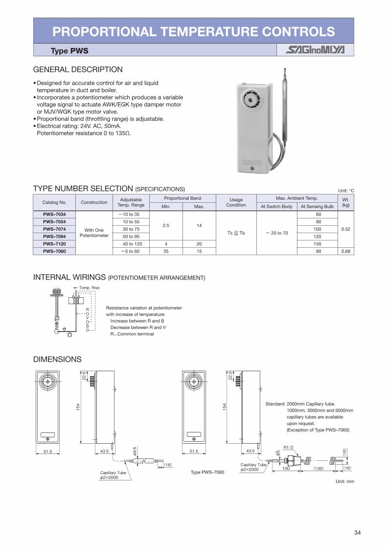
34
PROPORTIONAL TEMPERATURE CONTROLS Type PWS
GENERAL DESCRIPTION
•Designedforaccuratecontrolforairandliquidtemperatureinductandboiler.
•IncorporatesapotentiometerwhichproducesavariablevoltagesignaltoactuateAWK/EGKtypedampermotororMJV/WGKtypemotorvalve.
•Proportionalband(throttlingrange)isadjustable.•Electricalrating:24V.AC,50mA. Potentiometerresistance0to135Ω.
TYPENUMBERSELECTION(SPECIFICATIONS)
INTERNAL WIRINGS (POTENTIOMETERARRANGEMENT)
R
V
B
Temp. Rise
DIMENSIONS
51.5 43.5
(16)
Capillary Tubeφ2×2000
φ9.5
154
22.5
51.5 43.5
154
22.5
(130)100
R1/2
Capillary Tubeφ2×2000 (16)
φ5
(16)
Resistancevariationatpotentiometerwithincreaseoftemperature:IncreasebetweenRandBDecreasebetweenRandVR...Commonterminal
Standard:2000mmCapillarytube. 1000mm,3000mmand5000mm capillarytubesareavailable uponrequest. (ExceptionofTypePWS–7060)
Type PWS–7060
Unit:mm
Unit:°C
CatalogNo. Construction Adjustable Temp.Range
ProportionalBand Usage Condition
Max.AmbientTemp. Wt.(kg)Min. Max. AtSwitchBody AtSensingBulb
PWS–7034
WithOnePotentiometer
−10to35
2.5 14
TS TB − 20to70
60
0.52
PWS–7054 10to55 80
PWS–7074 30to75 100
PWS–7094 50to95 120
PWS–7120 40to120 4 20 150
PWS–7060 −5to60 35 15 90 0.68

35
ROOM THERMOSTATS Type ARS
GENERAL DESCRIPTION
•Highqualityroomthermostatforheatingorcooling.•Usedforloworlinevoltage.•Easytoadjustwithdialknob.•Dial stopper screwprevents unauthorizedchangeofsetting.
CONTACT FUNCTIONS
Arrowindicatestemp.rise.
SPECIFICATIONS
•Ambienttemperature:−20to50°C(Double-digittype) −10to50°C(Propotionaltype)
TYPENUMBERSELECTIONDouble-digittype Unit:°C
CatalogNo. RangeDifferential Step
Differential
FactorySetting Wt.(kg)Type ContactType Temp. SpecialApplication Min. Max. Off(On) On(Off)
ARS–C1
20−
(Standard・Type)
0 20
Approx.1.5−
(8.5) 10
0.17
30 10 30 (18.5) 20
40 20 40 (23.5) 25
20
S
0 20 (8.5) 10
30 10 30 (18.5) 20
40 20 40 (23.5) 25
S6 30 −(Standard・Type) 10 30 Approx.2
HeatSide(18.5)LowSide(16.5)
2018
0.22
Propotionaltype Unit:°C
CatalogNo. RangeDifferential FactorySetting Wt.
(kg)Type ContactType Temp. SpecialApplication Min. Max.
ARS– P1 30
−(Standard・Type)
10 30 Approx.225
CentervalueofProportionalband0.17
S
ELECTRICAL RATINGS
Minimumcontactcapacity:50mA
CatalogNo. ARS−C1 ARS−S6
RatedVoltage(V)RatedCurrent(A)
PowerFactor (cosφ)
AC DC AC
125 250 24 125 250
Non-InductiveCurrent 1.0 6 3 2 4 2
InductiveCurrent
FullLoad 0.75 6 3 1 4 2
InrushCurrent − 24 12 10 16 8
CatalogNo. ARS−P1
RatedVoltage(V)RatedCurrent(A)
AC
24
Allowablecurrentvalue 50mA
Resistanceofthepotentiometer 135Ω
H C L H C L H C LHC L BR VRB V
C1 Standard TypeC1 **S Type
(With HEAT‒ COOL Switch) S6 TypePropotional Standard Type
Propotional **S Type(With HEAT‒ COOL Switch)
HEAT‒COOL Switch
HEATCOOL COOL HEAT
HEAT‒COOL Switch
HEATCOOL COOL HEAT
Low temp. side High temp. side

36
APPLICATIONSAMPLES
Arrowindicatestemp.rise.
C L H
H C L
MV FM
Change over heating and cooling byoutside manual switch Fan coil unit
Power PowerMotor valve Fan
motor
HEATCOOLCOOLHEAT
HeatingUnit
CoolingUnit
–C1 –C1**S
DIMENSIONS
Unit:mm
19.5
15539.5
6876
34
90
80
Wall mounting holesφ4.5Sub-Base (φ4.5×5.5 )
Wall mounting holesφ4.5×5.5 (φ4.5)
Mounting pitch 66.7
( ):S630
Unit:mm
108
5
7
40
60
4-R10
98
66.7
83.5
66.74-M4×0.7 Body mounting holes
Wall mounting holes(M4 Countersunk screw)
φ5
3.5
A
12
A : Lead wire hole shape (ARS‒AE02)
t 0.8
9
(M4 Countersunk screw)Wall mounting holes
PartsNo. Leadwirehole
ARS–AE01 NotExist
ARS–AE02 Exist
OPTIONAL PARTSMountingpitch83.5plate(ARS–AE01,ARS–AE02)

37
ROOM THERMOSTATS Type WRS
GENERAL DESCRIPTION
•Forfancoilunitsandairconditioners.•Usedforloworlinevoltage.•VariousmodelsavailablewithFanSelectorswitchand/orHeat-Off-Coolchangeoverswitching.
•Usingadiaphragmelement, it assureshigh reliabilityandaccuratecontrol.
•Ambienttemperature:− 20to50°C
TYPENUMBERSELECTION(SPECIFICATIONS)
ELECTRICAL RATINGS
Minimumcontactcapacity:50mA
・ChangeoverswitchofHEAT–COOLonWRS–C130X1isonlyforchangingswitchmechanismofroomthermostatitselfbetweenHIGHCUT(HEATING)and LOWCUT(COOLING)accordingtosystemrequirement.
・Pleaserefertotheapplicationsampleandwiringdiagram.
Unit:°C
CONTACT FUNCTIONS
DIMENSIONS
HEAT
L M H
COOL
OFF ON
20 2515
90
133
4215
Base
19
2020
System SwitchesUnit:mm
CatalogNo. Sub-BaseFunction Range
Differential Wt. (kg)Type Contact&
Temp.RangeSpecial
Application ChangeoverSwitch FanSwitch Min. Max.
WRS– C130
X1 ON–OFF,HEAT–COOL
HIGH–MED–LOW 10 30Approx.
1.5 (Fixed)
0.25X2 ON–OFF
X7 ON–OFF,HEAT–COOL
RatedVoltage(V)RatedCurrent(A)
PowerFactor(cosφ)
125V.AC 250V.AC
Non-InductiveCurrent 16 3
InductiveCurrent
FullLoad 0.75
InrushCurrent − 24 12
Type WRS–C130X1 WRS–C130X2 WRS–C130X7
InternalWiring
Arrowindicatestemp.rise.
TO FAN SPEEDCONTROL
OFF HIGH
MED.
LOW
ONTEMP. RISE
HEAT
COOLTO MOTOR VALVE
L1
ON
OFF L
HC
YELLOW
BLACK
BLUE
GRAY
ORANGE
TO FAN SPEEDCONTROL
TO COOLINGCONTROLTO HEATING CONTROL
OFF HIGH
MED.
LOW
TEMP. RISE
L1
ON
OFF
LC
H
YELLOW
BLACK
BLUE
ORANGE
BROWN
RED
TO FAN SPEEDCONTROL
OFF
ONTEMP. RISE
HEAT
COOLHEAT
COOL
L1TO HEATING CONTROLTO COOLING CONTROL
ON
OFF
LC
H
YELLOW
BLACK
BLUE
GRAYWHITEORANGE
HIGH
MED.
LOW

38
MinimumContactCapacity:50mA
ROOM HUMIDISTATS Type AHS
GENERAL DESCRIPTION
•Accuratehumiditycontrolassuredbynylonribbon.•Usedforloworlinevoltage.•Easyadjustmentbydialknob.•Dial stopper screwprevents unauthorizedchangeofsetting.
SPECIFICATIONS
ELECTRICAL RATINGS
DIMENSIONS80
90
3439.5
76
Cover
Body
Sub-Base
Adjusting Dial Knob
68
CONTACT FUNCTIONSInternal Wiring
Application and Wiring Examples
H
H C L
C L
H C L
Relay etc. forDehumidifyingEquipment
Power Power
Humidifying ControlDehumidifying Control
Solenoid Valve,Relay etc. forHumidifyingEquipment
Arrowmarkindicateshumidityincrease.
Unit:%RH
Unit:mm
CatalogNo. ContactRange
Differential AmbientTemp. onUse(°C)
Wt. (kg)Min Max.
AHS–C1090 SPDT 30 90 Approx.5 10to40 0.17
RatedVoltage(V)RatedCurrent(A)
PowerFactor(cosφ)
125V.AC 250V.AC 24V.DC
Non-InductiveCurrent 1.0 4.5 2 1
InductiveCurrent
FullLoad 0.75 3 1.5 0.4
InrushCurrent − 12 6 2
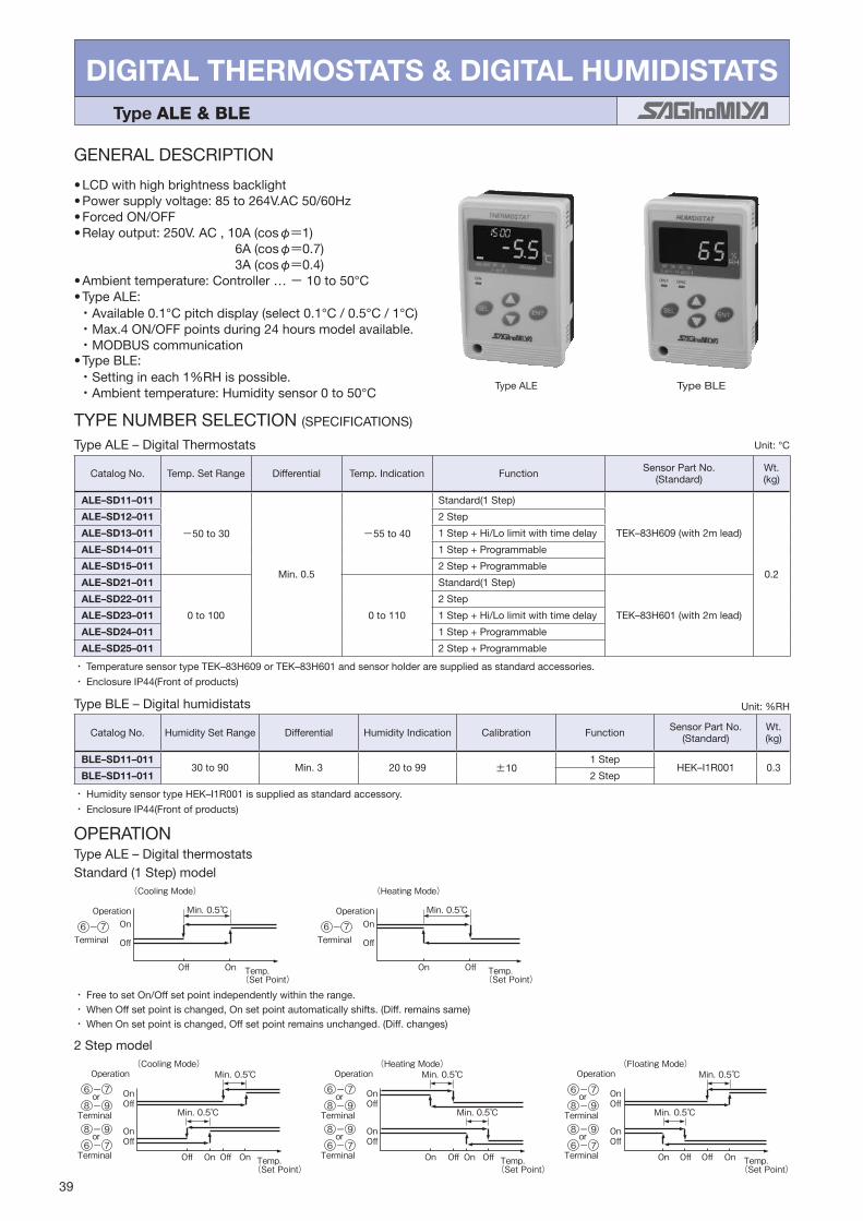
39
DIGITAL THERMOSTATS & DIGITAL HUMIDISTATS Type ALE & BLE
GENERAL DESCRIPTION
•LCDwithhighbrightnessbacklight•Powersupplyvoltage:85to264V.AC50/60Hz•ForcedON/OFF•Relayoutput:250V.AC,10A(cosφ=1) 6A(cosφ=0.7) 3A(cosφ=0.4)•Ambienttemperature:Controller…− 10to50°C•TypeALE:・Available0.1°Cpitchdisplay(select0.1°C/0.5°C/1°C)・Max.4ON/OFFpointsduring24hoursmodelavailable.・MODBUScommunication•TypeBLE:・Settingineach1%RHispossible.・Ambienttemperature:Humiditysensor0to50°C
TypeBLEType ALE
TYPENUMBERSELECTION(SPECIFICATIONS)
TypeALE–DigitalThermostats
・・TemperaturesensortypeTEK–83H609orTEK–83H601andsensorholderaresuppliedasstandardaccessories.
・・EnclosureIP44(Frontofproducts)
Unit:°C
CatalogNo. Temp.SetRange Differential Temp.Indication Function SensorPartNo. (Standard)
Wt.(kg)
ALE–SD11–011
−50to30
Min.0.5
−55to40
Standard(1Step)
TEK–83H609(with2mlead)
0.2
ALE–SD12–011 2Step
ALE–SD13–011 1Step+Hi/Lolimitwithtimedelay
ALE–SD14–011 1Step+Programmable
ALE–SD15–011 2Step+Programmable
ALE–SD21–011
0to100 0to110
Standard(1Step)
TEK–83H601(with2mlead)
ALE–SD22–011 2Step
ALE–SD23–011 1Step+Hi/Lolimitwithtimedelay
ALE–SD24–011 1Step+Programmable
ALE–SD25–011 2Step+Programmable
TypeBLE–Digitalhumidistats Unit:%RH
CatalogNo. HumiditySetRange Differential HumidityIndication Calibration Function SensorPartNo.(Standard)
Wt.(kg)
BLE–SD11–01130to90 Min.3 20to99 ±10
1StepHEK–I1R001 0.3
BLE–SD11–011 2Step
・・HumiditysensortypeHEK–I1R001issuppliedasstandardaccessory.
・・EnclosureIP44(Frontofproducts)
OPERATION
2Stepmodel(Cooling Mode)
On
Off OffOn On Temp.(Set Point)
Off
OnOff
Operation Operation(Floating Mode)
On
Off OffOn On Temp.(Set Point)
Off
OnOff
Operation(Heating Mode)
On
Off OffOn On Temp.(Set Point)
Off
OnOff
Min. 0.5
Min. 0.5
Min. 0.5
Min. 0.5
Min. 0.5
Min. 0.5
or6 - 7
Terminal8 - 9
or8 - 9
Terminal6 - 7
or
Terminal8 - 9
or8 - 9
Terminal6 - 7
6 - 7or6 - 7
Terminal8 - 9
or8 - 9
Terminal6 - 7
TypeALE–DigitalthermostatsStandard(1Step)model
(Cooling Mode)
OnMin. 0.5
Off On Temp.(Set Point)
OffTerminal
Operation
6 - 7
(Heating Mode)
OnMin. 0.5
OffOn Temp.(Set Point)
OffTerminal
Operation
6 - 7
・・FreetosetOn/Offsetpointindependentlywithintherange.・・WhenOffsetpointischanged,Onsetpointautomaticallyshifts.(Diff.remainssame)・・WhenOnsetpointischanged,Offsetpointremainsunchanged.(Diff.changes)

40
1 Step + Hi/Lo limit with time delay model
On
OffLo Limit Hi LimitOn Temp.(Set Point)
Off
On
Off
Terminal
Operation
8 - 9
Terminal6 - 7
Lo limit setting range
Lo Limit Time Set(Lo limit Func. starts after0 to 120 min. )
Hi Limit Time Set(Hi limit Func. starts after0 to 120 min. )
Hi limit setting rangeMin. 0.5
On
OnLo Limit Hi LimitOff Temp.(Set Point)
Off
On
Off
Terminal
Operation
8 - 9
Terminal6 - 7
Lo limit setting range
Lo Limit Time Set(Lo limit Func. starts after0 to 120 min. )
Hi Limit Time Set(Hi limit Func. starts after0 to 120 min. )
Hi limit setting rangeMin. 0.5
・ Hi/Lo limit output is reset manualy (Push reset: Push ENT Key in 2 sec or power off)
・ Delay Timer can be set in the time range from 0 to 120 min respectively.
Min. 0.5
Off On On Off
Min. 0.5
1 Step + Programmable model
Off
On
12:00 18:00 24:00
1 432
5
7
6
12
8
6
12
6:000:00
8
9
10
10On
6Off
1 2
12:00 18:00 24:006:000:00
Stop control
Programmable functionMax. 4 ON/OFF points during 24 hours model available.
Item1:6:00 OFF 6°C / ON 9°CItem2:9:00 OFF 5°C / ON 7°CItem3:18:00 OFF 6°C / ON 10°CItem4:21:00 OFF 8°C / ON 12°C
This program performs the following operations.
※This model can combine the settings of program example 1 and 2.In this case also a combination of up to 4 points within 24 hours.
Temp.(Set Point)
Temp.(Set Point)
[Program example 1]Change the set temperature four times a day at the specified time.
Stop control
[Program example 2]Stop control in the night (20:00 to 5:00) Item1:5:00 OFF 6°C / ON 9°CItem2:20:00 OFF 5°C / ON 7°C
This program performs the following operations.
Min. 3%RH
Type BLE – Digital humidistats
Standard (1 Step) model
・Change the set temperature (ON / OFF) at the specified time. ・Stop the control at the specified time.
Operation Operation
(Dehumidity Mode) (Humidity Mode)
(Cooling Mode) (Heating Mode)
Terminal6 - 7
Off
On
Off
On
Off On On Off(Set Point) (Set Point)
Operation Operation
Terminal6 - 7
Off
On
Off
On
Min. 3%RH
Humidity Humidity
・ Free to set On/Off set point independently within the range.・ When Off set point is changed, On set point automatically shifts. (Diff. remains same)・ When On set point is changed, Off set point remains unchanged. (Diff. changes)
・ Free to set On/Off set point independently within the range.・ When Off set point is changed, On set point automatically shifts. (Diff. remains same)・ When On set point is changed, Off set point remains unchanged. (Diff. changes)
2
Terminal6 - 7
Terminal6 - 7
1Step+Hi/Lolimitwithtimedelaymodel
・・FreetosetOn/Offsetpointindependentlywithintherange.・・WhenOffsetpointischanged,Onsetpointautomaticallyshifts.(Diff.remainssame)・・WhenOnsetpointischanged,Offsetpointremainsunchanged.(Diff.changes)
TypeBLE–Digitalhumidistats
・・Hi/Lolimitoutputisresetmanualy(Pushreset:Push ENT Keyin2secorpoweroff)
・・DelayTimercanbesetinthetimerangefrom0to120minrespectively.
1Step+Programmablemodel
・・FreetosetOn/Offsetpointindependentlywithintherange.・・WhenOffsetpointischanged,Onsetpointautomaticallyshifts.(Diff.remainssame)・・WhenOnsetpointischanged,Offsetpointremainsunchanged.(Diff.changes)
※This・model・can・combine・the・settings・of・program・example・1・and・2.In・this・case・also・a・combination・of・up・to・4・points・within・24・hours.
ProgrammablefunctionMax.4ON/OFFpointsduring24hoursmodelavailable.
・・・Change・the・set・temperature・(ON・/・OFF)・at・the・specified・time.・・・Stop・the・control・at・the・specified・time.
[Programexample1]Changethesettemperaturefourtimesadayatthespecifiedtime.
Item1:6:00・ OFF・6・/・ON・9Item2:9:00・ OFF・5・/・ON・7Item3:18:00・ OFF・6・/・ON・10Item4:21:00・ OFF・8・/・ON・12
This・program・performs・the・following・operations.
[Programexample2]Stopcontrolinthenight(20:00to5:00)
Item1:5:00・ OFF・6・/・ON・9Item2:20:00・ OFF・5・/・ON・7
This・program・performs・the・following・operations.
Standard(1Step)model
2Step+Programmablemodel・・Pleasecheckthe2Stepmodel

41
SensorPartNo.
ApplicableModel Dimension Remarks
TEK–83H609(Temperature)
ALE–SD11–011 ALE–SD12–011 ALE–SD13–011ALE–SD14–011ALE–SD15–011
•Ambienttemp.onusage:− 55to80°C•Whenthesensorisinuseundertheconditionofdew,waterdrippingoroutdoor,thesensorshouldbeverticallyinstalledwithleadwireoutletdownward.
•Sensorholderissuppliedasstandard.LeadWire:Blue
TEK–83H601(Temperature)
ALE–SD21–011 ALE–SD22–011 ALE–SD23–011ALE–SD24–011ALE–SD25–011
•Ambienttemp.onusage:− 40to110°C•Whenthesensorisinuseundertheconditionofdew,waterdrippingoroutdoor,thesensorshouldbeverticallyinstalledwithleadwireoutletdownward.
•Sensorholderissuppliedasstandard.LeadWire:Black
HEK–I1R001(Humidity)
BLE–SD11–011BLE–SD12–011
•Designedtoaccordroominterior.•Designedtobeinstalledwherecertainairflowrunsandtheroomhumidityisrepresented.
•Dependingonloadorotherconditions,humiditycontrolmaybecomedifficult.
ACCESSORIES
200030
φ6
Sensor Holder
1852
13
2-φ4.2
27
15
Followingsensorsareavailableasoption.(Ambienttemperaturesensorsareavailableuponrequest.)
Directimmersionsensorwithnipple........................... TEK–83N
Wallmountingsensor.................................................. TEK–83R
Surfacetemp.sensor.................................................. TEK–83E
Directimmersionsensorwithterminalcoverr............. TEK–83B
Bulbwell...................................................................... TEK–00N
102
105
83.5
71 33Elliptic Holes φ4.5
Sensor Mounting Bracket
3
Unit:mm
Unit:mm
6
7
8
9
RelayContact 1
RelayContact 2
Load
Load
Power Supplyfor Load
Power Supplyfor Load
On
Off On Off On(Set Point)
Off
OnOff
Terminal
or
or
On
On Off On Off
Off
OnOff
On
On Off Off On
Off
OnOff
Terminal
or
or
Terminal
or
or
2 Step model
(Dehumidity Mode) (Floating Mode)(Humidity Mode)
Terminal Humidity(Set Point)Humidity
(Set Point)HumidityTerminal
1
2
3
4
5
6
7
8
9
RelayContact 1
RelayContact 2
LoadSensor
Load
Power Supplyfor Load
Power Supplyfor LoadPower Supply
85 to 264V.AC
1
2
3
1
2
3
4
5Power Supply85 to 264V.AC
Sensor
(Type HEK)
6 - 7 (Control output):
WIRING DIAGRAMType ALE Type BLE
8 - 9
(Alarm output)
(Control output):
6 - 7 (Control output):
8 - 9 (Control output):
ACCESSORIES
Following sensors are available as option. (Ambient temperature sensors are available upon request.)
Operation Operation OperationMin. 3%RH
Standard (1 Step) model, 2 Step model,
1 Step model + Hi/Lo limit with time delay model,
and 1 Step model + Programmable model
2 Step model
1 Step model + Hi/Lo limit with time delay model
Standard (1 Step) model and 2 Step model
2 Step model
Terminal
:
Sensor Part No.
Applicable Model Dimension Remarks
TEK–83H601 (Temperature)
ALE–SD21–011 ALE–SD22–011 ALE–SD23–011ALE–SD24–011
• Ambient temp. on usage: -40 to 110°C • When the sensor is in use under the
condition of dew, water dripping or outdoor, the sensor should be vertically installed with lead wire outlet downward.
• Sensor holder is supplied as standard.Lead Wire:Black
TEK–83H609 (Temperature)
ALE–SD11–011 ALE–SD12–011 ALE–SD13–011ALE–SD14–011
• Ambient temp. on usage: -55 to 80°C • When the sensor is in use under the
condition of dew, water dripping or outdoor, the sensor should be vertically installed with lead wire outlet downward.
• Sensor holder is supplied as standard.Lead Wire:Blue
HEK–I1R001 (Humidity)
BLE–SD11–011BLE–SD12–011
• Designed to accord room interior. • Designed to be installed where certain air
ow runs and the room humidity is represented.
• Depending on load or other conditions, humidity control may become difcult.
200030
φ6
Sensor Holder
102
105
83.5
71 33Elliptic Holes φ4.5
Sensor Mounting Bracket
3
1852
13
2-φ4.2
27
15
Direct immersion sensor with nipple ........................... TEK–83N
Wall mounting sensor .................................................. TEK–83R
Surface temp. sensor .................................................. TEK–83E
Direct immersion sensor with terminal cover .............. TEK–83B
Bulb well ...................................................................... TEK–00N
Unit : mm
Unit : mm
6 - 7
6 - 7
8 - 9
8 - 9
6 - 7
6 - 7
8 - 9
8 - 9
6 - 7
6 - 7
8 - 9
8 - 9
3
Min. 3%RH
Min. 3%RH
Min. 3%RH
Min. 3%RH
Min. 3%RH
2Stepmodel
WIRINGDIAGRAM
6 - 7 :(Controloutput) :Standard(1Step)model,2Stepmodel,
1Stepmodel+Hi/Lolimitwithtimedelaymodel,
and1Stepmodel+Programmablemodel
8 - 9 :(Controloutput) :2Stepmodel
(Alarmoutput) :1Stepmodel+Hi/Lolimitwithtimedelaymodel
6 - 7 :(Controloutput):Standard(1Step)modeland2Stepmodel
8 - 9 :(Controloutput):2Stepmodel
Type ALE TypeBLE

42
83
127
11
Gasket
Front
Panel
SEL ENT
122
77
COOL HEAT OFF ONSET
ON
164410.5
54.5
71+1-0.5
2717
5050
26
116+1 -0.5
DIMENSIONS
TypeALE,BLE
OPERATION
TypeALE-AA02PanelMountBracketincludingGasket
WallMountInstallationDimension
PanelCutDimension
Unit:mm
Unit:mm
Communicationfunction
Type ALE
Thisproductallowsthefollowingoperationsusingthecommunicationfunction.SaginomiyaSeisakusho'smonitoringsoftwareallowsthefollowingchecksandoperationsonthePC.
•Monitoringcurrenttemperature•Checkingcurrentsettings•Switchingoperationmode(COOL/HEAT)•Registeringprogram•Settingtime•Savingmeasurementdata
•MonitoringoutputON/OFF•SettingOFF/ONsettingvalues•Settingcalibration•Enabling/disablingprogramfunction•Locking/unlockingkey
Thefollowingshowsasummaryofcommunicationspecifications.
* YouneedtoprovideanRS-485communicationconverterandacommunicationcablerequiredforcommunication.* Pleasedownloadthemonitoringsoftwarefromthesaginomiyawebsite.(Freeofcharge)
* Fordetailsoncommunicationspecifications,contactyourdealerorSaginomiyaSeisakusho.
・・Interface : IRS-485・・Connectionmethod : Two-wirehalf-duplexmulti-dropconnection・・Numberofconnectedunits : 16orless・・Protocol : Modbus・・Transmissionmode : RemoteTerminalUnit(RTU)

4343
DIGITAL THERMOSTATS Type TNE
GENERAL DESCRIPTION
•Compactdigital temperaturecontroller (48mm×48mm)formanyapplications.
•Highquality temperature controlwithplatinumandthermocoupletemperaturesensor(option).
•Twokindsofoutput-currentoutputandrelayoutput-areavailable.
•Various function such asPIDControl, Auto/ManualChangeoverandLockFunctionareinstalled.
•TwopointsoutputforHigh/Lowlimitalarm.•Powersupplyvoltage:100to240V.AC50/60Hz•Adaptivetemperaturesensor:Pt100,JPt100 Thermocouple(TypeK,J,R,T,N,S,B)
TYPENUMBERSELECTION(SPECIFICATIONS)
WIRINGDIAGRAM
DIMENSIONS MOUNTINGSIZE
1
2
3
4
5
6 11
12
13
14
15Fuse
Power Supply
Power Supply for Load
Power Supply for Load
B
b
A
PlatinumTemperature Sensor
ThermocoupleTemperature Sensor
LoadLoad
OUT1
AL2 AL1 1
2
3
4
5
6 11
12
13
14
15Fuse
Power Supply
Power Supply for Load
Power Supply for Load
B
b
A
PlatinumTemperature Sensor
ThermocoupleTemperature Sensor
LoadLoad
OUT1
AL2 AL1
or or
NO
C
TNE–SNPR–N21
Relay Output Current Output
TNE–SNPA–N21
+
-+
-
+
-
Panel(thickness:under 5mm)
248
48
776
Packing
FUNCMODE
AL1 AL2 RDY
PV
SVOUT1
•Indicator:Temperature…7Seg.GreenLED4digits Temperaturesetpoint…7Seg.RedLED4digits Controloutput…RedLED×3
Unit:mm
PanelCutoutSize
OPTIONAL PARTSPlatinumTemperatureSensor(Type:PEK–02H001)
+0.6
-0
45-0+0.6
45
48 or over
60 or over
WhiteWhite
Red50
300050
SUS Cap.
Lead Wire
φ4.8
bB
A
ACCESSORYFixingBracket
CatalogNo. Temp.SetRange ControlType ControlOutput AlarmOutput(Relay) Wt.(kg)
TNE–SNPR–N21 basedonaconnectionsensor
On/Off Relay(SPST250V.AC3A)SPST250V.AC2A×2 0.18
TNE–SNPA–N21 PID(Selftuning) Current(4to20mADC)
・・Ambienttemperature0to50
Temperaturerange:−70to140Resistancevalue:100Ω(0)

CONNECTION & ACCESSORIES・ ・・・・・・・・・・・・・・45–47
DRIP PROOF & WATER PROOF CONTROLS・・・・・・48–53
Series NS–W & NS–P
PR
ES
SU
RE
&T
EM
PE
RA
TU
RE
CO
NT
RO
LS IN
FOR
MA
TIO
N
PRESSURE &TEMPERATURE CONTROLS INFORMATION

45
CONNECTION & ACCESSORIES
NS PRESSURE CONTROLS NOMENCLATURECatalog No. is decided according to the specifications.
M1 N W G Q
Ⅰ Ⅱ Ⅲ ⅣExample: HNS – C1 30 X
Ⅰ N=SUS Bellows
Ⅱ W=Drip Proof, P=Water Proof (Except for Type HNS, WNS, YNS)
Ⅲ Connection Style.... Refer to Connection Table Below
Ⅳ Option....Special No.
ONS PROTECTION CONTROLS NOMENCLATURECatalog No. is decided according to the specifications.
N W G Q
ⅡⅠ Ⅲ ⅣExample: ONS – C1 06 X
Ⅰ N=SUS Bellows
Ⅱ W=Drip Proof
Ⅲ Connection Style.... Refer to Connection Table Below
Ⅳ Timer Specication.... Q1~Q12、Q25~Q36
Connection Table (for NS Series Pressure Controls )Size
Connection StyleCopper Steel
1/4" φ8 3/8" φ10 1/2" φ10.5
B FlareExcept Below (Stand.) B1 B2 B3 B4 −ANS B B1 B2 B3 B4 −
U Union U1 U2 − U (Stand.) − U3
G Female Thread
Rc G (Stand.) − G3 − G6 −G G1 − G4 − G7 −
NPT G2 − G5 − G8 −
M Male Thread
Except Below
R M02 − M01 (Stand.) − M07 −G M03 − M05 − M08 −
NPT M04 − M06 − M09 −
ANS
R M1 − M (Stand.) − M6 −G M2 − M4 − M7 −
NPT M3 − M5 − M8 −
K FlarelessDirect K1 K2 − K (Stand.) − −Connector − − − − − K3
SizeConnection Style 1000 mm 2000 mm
L Capillary L1 (Stand.) L2

46
NS TEMPERATURE CONTROLS NOMENCLATURECatalog No. is decided according to the specifications.
Example: TNS – C1 100 X M2 W L1 Q1
Ⅰ Ⅱ Ⅲ
Ⅰ W=Drip Proof, P=Water Proof
Ⅱ Connection Style.... Refer to Connection Table Below
Ⅲ Option....Special No.
Capillary Length Table
*・TNS–C1010XC to TNS–C1070XC: Capillary length are 1m to 5m
SizeConnection Style
Normal Nickel Plated
Except BNS BNS Except BNS BNS
1m Standard L1 Q012 L1Q012
2m L2 L2Q012
3m L3 L3Q012
5m L5 L5Q012
7m L7 L7Q012
10m L0 L0Q012
Except Above LQ LZ LQ012 LZQ012
(B) Flare (U) UnionPipe Thread
(G) Female (M) Male
(K) Flareless Type Connection(L) Capillary
Copper Pipe (Direct) Steel Pipe (Connector Option)
K3
Size A B C D E F G
φ1/4 φ6.5 17 12 7/16–20 UNF 0 20.5 26
φ8 φ8.2
22 17 5/8–18UNF 5 24.5 36φ3/8 φ9.7
φ10 φ10.2
φ1/2 φ12.9 24 22 3/4–16UNF 5 27.5 40
Size A B C D E F
φ6 6.2 14 14 M12 23 33
φ8 8.2 17 14 M14 23 33
φ10 10.2 19 17 M16 23 34
Type LL1 1000L2 2000
Size A B C
1/4"Rc1/4
19 23G1/4 1/4 NPT
3/8"Rc3/8
22 23G3/8 3/8 NPT
1/2"Rc1/2
27 27G1/2 1/2 NPT
Size A B C
1/4"R1/4
17 29G1/4 1/4 NPT
3/8"R3/8
19 29G3/8 3/8 NPT
1/2"R1/2
22 33G1/2 1/2 NPT
Size A
φ6 Copper φ6.5
φ8 Copper φ8.5
φ10 Copper φ10.5
φ10.5 Steel φ11.0
Connection Dimension Table
Hex. C
A
Hex. B
D(G)
EF
Hex. 22
Hex. 30
A
52740
A
Hex. B
C
A
Hex.BC
A
Hex.B
Hex.C
D Thread
(F)
E
(48.5)
(60.5)
10.7
Hex.19
M16
Hex.17
G Connection
1/4" Flare Nut
φ2.4 ×LCapillary Tube
Unit: mm

Name Body Bracket Bulb BracketType Parts No. Type Parts No. Type Parts No. Type Parts No.
YS, NS, FE Series
SNS–AE01(Standard Acce.) NS Series SNS–AE02 LWS
FWSRWS
LWS–AE08
ALS, BLS ALS–AE09
LWSPWS
(Except PWS-7060)LWS–AE12SNS–AE11
ALS, BLS ALS–AE02ALS, BLS ALS–AE01
Form
Size Max Press. Torque A B D E1/2" Static
Press. 1MPa12N・mor less
Hex. 24 Hex. 22 R1/2 (43)3/4" Hex. 32 Hex. 30 R3/4 (54)
Controls Catalog No. Size Parts No. SizeC
NS
TNS–C100 to C134CNS–C115 (M2) to C134 (M2)
1/2" TNS–AB01φ6
3/4" TNS–AB09
TNS–C1070TNS–C1010C to C1070C
1/2" TNS–AB04φ12.7
3/4" TNS–AB07
TNS–C1100 to C11501/2" TNS–AB17 φ12.7
Heat Proof3/4" TNS–AB18
INS–C1070M11/2" TNS–AB02
φ9.53/4" TNS–AB05
INS–C1120M1, C1150M11/2" TNS–AB15 φ9.5
Heat Proof3/4" TNS–AB16
WS
LWS–C1030 to C1094PWS–7034 to 7094
1/2" LWS–AB02φ9.5
3/4" LWS–AB05
LWS–C1120 to C1240PWS–7120
1/2" LWS–AB15 φ9.5Heat Proof3/4" LWS–AB16
LS
ALS–C1011 to C1050BLS–C1020
1/2" ALS–AB03φ10
3/4" ALS–AB06
ALS–C1090 1/2" ALS–AB10 φ10Heat Proof
Controls Catalog No. SizeParts No. Size
C×FCopper SUS
NS
TNS–C100 to C134CNS–C115 (M2) to C134 (M2)
1/2" TNS–AC01 TNS–AC46φ8×95
3/4" TNS–AC35 TNS–AC56
TNS–C1070 to C1150TNS–C1010C to C1070C
1/2" TNS–AC05 TNS–AC12
φ15×1153/4" TNS–AC09 TNS–AC14
INS–C1070M1 to C1150M11/2" TNS–AC02 TNS–AC11
φ12×953/4" TNS–AC06 TNS–AC13
WS
LWS–C1030 to C10901/2" LWS–AC15 LWS–AC21
φ12×1103/4" LWS–AC17 LWS–AC23
LWS–C1120 to 1160PWS–7120
1/2" LWS–AC19 LWS–AC25φ12×80
3/4" LWS–AC20 LWS–AC26
LWS–C1200 to C12401/2" LWS–AC48 LWS–AC50 φ12×80
Heat Proof3/4" LWS–AC49 LWS–AC51
LWS–C1034 to C1094PWS–7034 to 7094
1/2" LWS–AC16 LWS–AC22φ12×140
3/4" LWS–AC18 LWS–AC24
EWS–C1080 to C1160 1/2"EWS–AC27 − φ10.8×70
− EWS–AC28 φ12×75
LS ALS–C1011 to C1090BLS–C1020
1/2" ALS–AC03 ALS–AC36φ12×105
3/4" ALS–AC07 −
Size Max Press. Torque A B D E1/2" Static
Press. 3MPa12N・mor less
Hex. 24 R1/2 10 203/4" Hex. 24 R3/4 10 22
47
2725
(12.5)11.5
55.2
20 20 1010
60R3.5
7
24025
4-φ4.4
7.5
825
47(85)
282(120)
7.5
30
95
65
30
257
2040
5
25 8-φ4.4
2025
126
72
4-φ5.5
6 610
8674
163150
8040
15
3-M3×0.5
2-φ6.2
61
20 20
87565
2-φ4.4
φ9
Insert Holder, Protect Tube (For Temperature Controls)
Insert Holder Protect Tube
Insert Holder Protect Tube
E
B DA C
D E F
CA B
M5 Distance Piece Protect Tube Bulb
ACCESSORIESMounting Brackets
( ) SNS–AE11 Ambient temp.:−40 to 90

Catalog No.Range
Manual Reset Factory Setting Max. Working
PressureContact Function Wt. (kg)
Min. Max. Off (On) On (Off)
SNS–C102XM2 W, P −0.02−20cmHg 0.2 2Automatic operation on pressure decrease and
manual reset on pressure increase
0.025 0.25
ManualReset
0.5 5
Diagram 2
SNS–W:Approx.
1.1SNS–P:Approx.
0.6
SNS–C106XM2 W, P −0.06−50cmHg 0.6 6 0.2 2 1.5 15
SNS–C130XM2 W, P 0.5 5 3 30 2 20 3.3 33
48
DRIP PROOF & WATER PROOF CONTROLS SERIES NS–W & NS–P
GENERAL DESCRIPTION
•ApprovedbyvariousmarinestandardssuchasBureauVeritas, Lioyd's Register, Det Norske Veritas ∙ Germanischer Lioyd's, Nippon Kaiji Kyokai, ABS etc.
•Suitableforindoororoutdoorapplicationswherewaterdrips and dusts are apt to enter, such as marine refrigeration units or industrial plants.
•Externalwiringismadebycabtyrecableconnectionwithcable glands. Standard gland size: φ20mm Semi standard gland size: φ15mm
•Toorder,specifycatalogNo.with“W”or“P”. Example: Type SNS–C106XW Drip proof model Type SNS–C106XP Water proof model
Type SNS–W, FNS–W, ANS–W
Type SNS–P, FNS–P, ANS–P
TYPE NUMBER SELECTION (SPECIFICATIONS)
Automatic reset type
Type SNS–W/P − Drip proof and Water proof model of single function pressure controls.
Unit: MPa kgf/cm2
Manual reset type Unit: MPa kgf/cm2
*・Based on the 1–3 terminal connection.
*
Catalog No.Range Differential Factory Setting Max. Working
PressureContact Function Wt. (kg)
Min. Max. Min. Max. Off (On) On (Off)
SNS–C101X W −0.06 −50cmHg 0.1 1 0.015 0.15 0.05 0.50.025 0.25 0.05 0.5
0.3 3
Diagram 1
SNS–W:Approx.
1.1SNS–P:Approx.
0.6
SNS–C102X W, P −0.02 −20cmHg 0.2 2 0.025 0.25 0.15 1.5 0.5 5
SNS–C103X W, P −0.06 −50cmHg 0.3 3 0.035 0.350.2 2
0.05 0.5 0.15 1.5 1 10
SNS–C104X W, P −0.06 −50cmHg 0.4 4 0.04 0.4 0.1 1 0.2 2
1.5 15SNS–C106X W, P −0.06 −50cmHg 0.6 6 0.06 0.6 0.4 4 0.2 2 0.3 3
SNS–C110X W, P 0.1 1 1 10 0.1 1 0.3 3 0.4 4 0.6 6
SNS–C130X W, P 0.5 5 3 30 0.3 3 1 10 2 20 2.5 25 3.3 33
SNS–C135X W, P 1 10 3.5 35 0.5 5 1.5 15 2.5 25 3 30 3.8 38
ELECTRICAL RATINGS CONTACT FUNCTIONS
15
31
5
3
13
51
3
5M1
M2
Diagram 1 Diagram 2
↑・: Operating direction on press. increase at High Press. SideM2↑・: Operating direction on manual reset
Rated Voltage (V)Rated Current (A)
Power Factor (cosφ) 125/250V. AC
Non-Inductive Current 112
Inductive Current
Full Load 0.75
Inrush Current − 72
Diagram 1 & 2
1 Common Terminal
3 Close on Pressure Increase
5 Close on Pressure Decrease
Minimum contact capacity: 50mA

49
DIMENSIONS
11.5
(51)
8880 10 (63)
3
2828
8
20 7
150
1820
182967
67
(24)
Conduit Gland
Flare Nut
110
9
(88)
11
33 37.5
98
114
8 8
6
(65.5)
37.5
Conduit Gland
Flare NutUnit: mm
Type SNS–P, FNS–P, ANS–P Type SNS–W, FNS–W, ANS–W
Type DNS–W/P − Drip proof and Water proof model of dual function pressure controls
Type DNS–WType DNS–P
TYPE NUMBER SELECTION (SPECIFICATIONS)
Automatic reset type Unit: MPa kgf/cm2
Catalog No. Pressure Side
Range Differential Factory Setting Max. Working Pressure
Contact Function Wt. (kg)
Min. Max. Min. Max. Off On
DNS–D304X W, PLow Side −0.06 −50cmHg 0.4 6 0.04 0.4 0.2 2 0.1 1 0.2 2 1.5 15
Diagram3 DNS–W:
Approx.1.4
DNS–P:Approx.
0.9
High Side 0.8 8 3 30 Approx. 0.4 fixed. Approx. 4 fixed. 2 20 1.6 16 3.3 33
DNS–D306X W, PLow Side −0.06 −50cmHg 0.6 6 0.06 0.6 0.4 4 0.2 2 0.3 3 1.5 15
High Side 0.8 8 3 30 Approx. 0.4 fixed. Approx. 4 fixed. 2 20 1.6 16 3.3 33
DNS–D604X W, PLow Side −0.06 −50cmHg 0.4 6 0.04 0.4 0.2 2 0.1 1 0.2 2 1.5 15
Diagram5
High Side 0.8 8 3 30 Approx. 0.4 fixed. Approx. 4 fixed. 2 20 1.6 16 3.3 33
DNS–D606X W, PLow Side −0.06 −50cmHg 0.6 6 0.06 0.6 0.4 4 0.2 2 0.3 3 1.5 15
High Side 0.8 8 3 30 Approx. 0.4 fixed. Approx. 4 fixed. 2 20 1.6 16 3.3 33
Manual reset type Unit: MPa kgf/cm2
Catalog No. Pressure Side
Range Differential Factory Setting Max. Working Pressure
Contact Function Wt. (kg)
Min. Max. Min. Max. Off On
DNS–D304XM W, P
Low Side −0.06 −50cmHg 0.4 4 0.04 0.4 0.2 2 0.1 1 0.2 2 1.5 15
Diagram 4
DNS–W:Approx.
1.4DNS–P:Approx.
0.9
High Side 0.8 8 3 30Automatic operation on pressure
increase and manual reset on pressure decrease
2 20 manualreset 3.3 33
DNS–D306XM W, P
Low Side −0.06−50cmHg 0.4 4 0.06 0.6 0.4 4 0.2 2 0.3 3 1.5 15
High Side 0.8 8 3 30Automatic operation on pressure
increase and manual reset on pressure decrease
2 20 manualreset 3.3 33
DNS–D604XM W, P
Low Side −0.06−50cmHg 0.4 4 0.04 0.4 0.2 2 0.1 1 0.2 2 1.5 15
Diagram 6
High Side 0.8 8 3 30Automatic operation on pressure
increase and manual reset on pressure decrease
2 20 manualreset 3.3 33
DNS–D606XM W, P
Low Side −0.06−50cmHg 0.6 6 0.06 0.6 0.4 4 0.2 2 0.3 3 1.5 15
High Side 0.8 8 3 30Automatic operation on pressure
increase and manual reset on pressure decrease
2 20 manualreset 3.3 33
DNS–D606XMM W
Low Side −0.06−50cmHg 0.6 6Automatic operation on pressure
decrease and manual reset on pressure increase
0.2 2manualreset
1.5 15
Diagram 7
High Side 0.8 8 3 30Automatic operation on pressure
increase and manual reset on pressure decrease
2 20 3.3 33

50
Unit: mm
CONTACT FUNCTIONS
1
4
H2
L
3 1
4
H
M
2
L
3 1
45
62 H
L
3 1
45
62 H
ML
3 1
45
62 H
MLM
3
L↓ : Operating direction on press. increase at Low Press. SideH↑ : Operating direction on press. increase at High Press. SideM↓ : Operating direction on manual reset
Diagram 3 Diagram 4 Diagram 5 Diagram 6 Diagram 7
ELECTRICAL RATINGSRated Voltage (V)
Rated Current (A)Power Factor
(cosφ) 125/250V. AC
Non-Inductive Current 112
Inductive Current Full Load 0.75
Inrush Current − 72
DIMENSIONSType DNS–P Type DNS–W
11.5
(51) Conduit Gland
88
80
(99) 10 (20.5)(63)
3
23
28
28
8
20 7
63
192
1824
18
8888
29
111137
31 357.5 7.5
(61)
120135
28
9
(90)
11
627.532.540
(65)Conduit GlandFlare Nut
Reset Button
Type HNS–W − Drip proof model of single function hight pressure controls
Catalog No.Range
DifferentialFactory Setting Max. Working
Pressure Wt. (kg)Min. Max. Off On
HNS–C130X W 0.8 8
3 30
0.3 to 0.5 Fixed3 to 5 fixed
2 20
1.6 16
3.333 Approx. 1.1
Catalog No.Range
Manual Reset Factory Setting Max. Working
Pressure Wt. (kg)Min. Max. Off On
HNS–C130XM1 W 0.8 8
3 30
Automatic operation on pressure increase and manual reset on
pressure decrease
2 20
manualreset
3.333 Approx. 1.1
TYPE NUMBER SELECTION (SPECIFICATIONS)
Automatic reset type Unit: MPa kgf/cm2
For specifications, electrical ratings, and contact functions, refer to page 13, 14.
For specifications, electrical ratings, and contact functions, refer to page 13, 14.
Manual reset type Unit: MPa kgf/cm2
*
*
HNS–W

51
・Type FNS–W/P & ANS–W/P − Drip proof and Water droof model of single function pressure controls
DIMENSIONS
11.5
(37)
(17)
8880 10 (63)(14)
3
2328
8
20 7
150
1818
6767
Conduit Gland
Flare Nut
Reset Button
TYPE NUMBER SELECTION (SPECIFICATIONS)
Type FNS – Fixed narrow differential
Type ANS – Adjustable narrow differential
For specifications, electrical ratings, and contact functions, refer to page 19, 20.For dimensions, refer to page 49.
For specifications, electrical ratings, and contact functions, refer to page 19, 20.For dimensions, refer to page 49.
Unit: MPa kgf/cm2
Unit: MPa kgf/cm2
Catalog No.Range
DifferentialFactory Setting Max.
Working Pressure
Wt. (kg)Min. Max.
Min. Max. Bottom Top Bottom Top Off On
ANS–C1**XB W, P−0.06 −50cmHg
to1 10
0.1 1to
3.5 35
0.007 0.07to
0.12 1.2
0.007 0.07to
0.2 2.0
0.014 0.14to
0.24 2.4
0.015 0.15to
0.39 3.9
0.018 0.18to
2.82 28.2
0.025 0.25to
3 30
0.3 3to
3.8 38
ANS–W:Approx.
1.3ANS–P:Approx.
0.6
Catalog No.Range Differential Factory Setting Max. Working
Pressure Wt. (kg)Min. Max. Fixed Off On
FNS–C1**X W, P−0.06 −50cmHg
to0.5 5
0.1 1to
3 30
0.006 Approx. 0.06 Approx.to
0.12 Approx. 1.2 Approx.
(0.019) (0.19)to
(2.38) (23.8)
0.025 0.25to
2.5 25
0.3 3to
3.3 33
FNS–W:Approx.
1.3FNS–P:Approx.
0.6
Unit: mm
*・FNS–C101X, type W is the only available.
*・ANS–C101XB, type W is the only available.
FNS–W, ANS–W
DIMENSIONSType FNS–W, Type ANS–W
11.5
51Conduit GlandJIS F 8801 C‐20C
8880 10 (63)
3
28
8
20 7
1818
202967
67
φ6(1/4)Flare Nut 15
0
(24)
28
Name Plate
Type HNS–W

52
Type ONS–W , WNS–W & YNS-W − Drip proof model of differential pressure controls
TYPE NUMBER SELECTION (SPECIFICATIONS)
Type ONS – for oil protection Unit: MPa kgf/cm2
ONS–W WNS–W, YNS–W
Catalog No.Range Differential Timer Specification
Wt. (kg)Min. Max. Fixed Delay Time (sec.) Timer Voltage Timer Circuit
ONS–C106X W 0.05 0.5 0.35 3.5 Approx. 0.05Approx. 0.5 45, 90, 110 100/200V. AC 110/220V. AC
115/230V. AC 120/240V. ACStandard (SPST)
without Alarm Contact (SPDT)Approx.
1.3
Type WNS – for water, air and fluorinated refrigerant Unit: MPa kgf/cm2
Catalog No.Range Differential Factory Setting Max. Working
Pressure
Limit of Press. Differential(HP> LP)
Wt. (kg)Min. Max. Min. Max. Off On
WNS–C102XW
0.03 0.3 0.2 2 0.03 0.3 0.15 1.5 0.05 0.5 0.02 0.2 0.5 5 0.5 5 Approx.1.3WNS–C106X 0.05 0.5 0.35 3.5 0.05 0.5 0.25 2.5 0.1 1.0 0.05 0.5 1.5 15 1.5 15
For specifications, electrical ratings, and contact functions, refer to page 21, 22.
For specifications, electrical ratings, and contact functions, refer to page 23.
Unit: mm
DIMENSIONSType ONS–W Type WNS–W, YNS-W
11.5
(37)
(17)
8880 10 (63)(14)
3
2328
8
20 7
11.5
(51)
8 88 10101 (20.5)
20 7
150
1818
6767
11.5
8880 10
16101(97)
(63)3
2828
8
20 7 150
18
20
182967
67
2832
3236
18
3(65)
(12)
18100
55171
11.5
(51)
8 88 10106(100) (20.5)
20 7
2832
3236
18
3(65)
18100
55171
(20.5)
Conduit Gland
Flare Nut
Reset Button
Conduit Gland
Flare Nut
Reset Button
Conduit Gland
Flare Nut
Conduit Gland
Capillary Tube
11.5
(37)
(17)
8880 10 (63)(14)
3
2328
8
20 7
11.5
(51)
8 88 10101 (20.5)
20 7
150
1818
6767
11.5
8880 10
16101(97)
(63)3
2828
8
20 7 150
18
20
182967
67
2832
3236
18
3(65)
(12)
18100
55171
11.5
(51)
8 88 10106(100) (20.5)
20 7
2832
3236
18
3(65)
18100
55171
(20.5)
Conduit Gland
Flare Nut
Reset Button
Conduit Gland
Flare Nut
Reset Button
Conduit Gland
Flare Nut
Conduit Gland
Capillary Tube
Type YNS – for water, air and fluorinated refrigerant Unit: MPa kgf/cm2
Catalog No.Range Differential Factory Setting Max. Working
Pressure
Limit of Press. Differential(HP> LP)
Wt. (kg)Min. Max. Fixed Off On
YNS–C102XW
0.02 0.2 0.2 2 Approx. 0.015 Approx. 0.15 0.05 0.5 (0.035) (0.35) 0.5 5 0.5 5 Approx.1.3YNS–C106X 0.025 0.25 0.35 3.5 Approx. 0.025 Approx. 0.25 0.15 1.5 (0.125) (1.25) 1.5 15 1.5 15
For specifications, electrical ratings, and contact functions, refer to page 23.

53
・Type TNS–W/P, CNS–W/P & INS–W − Drip proof and Water proof model of temperature controls
Type TNS–P, CNS–PType TNS–W, TNS–W
11.5
(37)
(17)
8880 10 (63)(14)
3
2328
8
20 7
11.5
(51)
8 88 10101 (20.5)
20 7
150
1818
6767
11.5
8880 10
16101(97)
(63)3
2828
8
20 7 150
18
20
182967
67
2832
3236
18
3(65)
(12)
18100
55171
11.5
(51)
8 88 10106(100) (20.5)
20 7
2832
3236
18
3(65)
18100
55171
(20.5)
Conduit Gland
Flare Nut
Reset Button
Conduit Gland
Flare Nut
Reset Button
Conduit Gland
Flare Nut
Conduit Gland
Capillary Tube
20 7
88880 10
(13)
(37)
11.5
(63)(14)3
2328 15
0
1818
6767
Capillary Tube
Reset Button
Conduit Gland
TYPE NUMBER SELECTION (SPECIFICATIONS)
Type TNS – Automatic reset type
For specifications, electrical ratings, and contact functions, refer to page 31, 32.
Unit: °C
Catalog No.Range Differential Factory Setting Limit
Temp.Usage
Condition Wt. (kg)Min. Max. Min. Max. Off (On) On (Off)
TNS–C1**X W, P −45 to 115 0 to 150 2 to 5 15, 20 −18 to 140 −15 to 145 40 to 180 TS>TB, TS<TB, TS TB
TNS–W:Approx. 1.3
TNS–P:Approx. 0.7
Type CNS – Automatic reset type
For specifications, electrical ratings, and contact functions, refer to page 31, 32.
Unit: °C
Catalog No.Range
DifferentialFactory Setting Limit
Temp.Usage
Condition Wt. (kg)Min. Max. Off On
CNS–C1**X W, P −35 to 0 −15 to 35 Bottom 4 Top 3 −28 to 17 −25 to 20 70 TS > TB
CNS–W:Approx. 1.3
CNS–P:Approx. 0.7
For specifications, electrical ratings, and contact functions, refer to page 31, 32.
Type INS – Manual reset type Unit: °C
Catalog No.Range
Manual ResetFactory Setting Limit
Temp.Usage
ConditionWt. (kg)Min. Max. Off On
INS–C1070XM1 W 25 to 115 75 to 150Automatic operation on temperature
increase and manual reset on temperature decrease.
Manual Reset 65 to 140 115 to 180 TS < TB Approx. 1.3
For specifications, electrical ratings, and contact functions, refer to page 31, 32.
Type CNS – Manual reset type Unit: °C
Catalog No.Range
Manual ResetFactory Setting Limit
Temp.Usage
ConditionWt. (kg)Min. Max. Off On
CNS–C1**XM2 W, P −35 to 0 −15 to 35Automatic operation on temperature
decrease and manual reset on temperature increase.
−28 to 17Manual Reset 70 TS > TB
CNS–W:Approx. 1.3
CNS–P:Approx. 0.7
DIMENSIONS
110
9
114988 8
(16)
33 37.5
11(88)
6
(65.5)
32.5
37.5
Capillary Tube
Conduit Gland
Type TNS–P, CNS–P Type TNS–W, CNS–W
Type INS–W
Unit: mm

GENERAL INFORMATION・ ・・・・・・・・・・・・・・・・・・・55–56
EXPANSION VALVES・ ・・・・・・・・・・・・・・・・・・・・・・・・・ 57
Type ARX
EXPANSION VALVES・ ・・・・・・・・・・・・・・・・・・・・・・・58–60
Type QCX & RCX
EXPANSION VALVES・ ・・・・・・・・・・・・・・・・・・・・・・・61–63
Type SCX
EXPANSION VALVES・ ・・・・・・・・・・・・・・・・・・・・・・・・・ 64
Type BHX
EXPANSION VALVES・ ・・・・・・・・・・・・・・・・・・・・・・・65–66
Type ATX (R410A)
EXPANSION VALVES・ ・・・・・・・・・・・・・・・・・・・・・・・67–68
Type ATX
EXPANSION VALVES・ ・・・・・・・・・・・・・・・・・・・・・・・69–70
Type AEX
ELECTRONIC EXPANSION VALVES・・・・・・・・・・・・・71–73
Type UKV, VKV & AKV
ELECTRONIC EXPANSION VALVES・・・・・・・・・・・・・・・ 74
Type UKV–F
PULSE CONVERTERS・ ・・・・・・・・・・・・・・・・・・・・・・・・ 75
Type LNE
EX
PAN
SIO
N V
ALV
ES
EXPANSION VALVES

55
EXPANSION VALVES GENERAL INFORMATION
VALVE SELECTION
In order to properly select Expansion Valves, the following items should be considered.
1) Required valve capacity should be based on the actual system operating conditions rather than the normal valve capacity rating.
2) When there exists an appreciable pressure drop between the valve outlet and the evaporator outlet, i.e., above 0.02 MPa 0.2 kgf/cm2, or when a pressure drop type of refrigerant distributor is used at the evaporator inlet, the valve should have the external equalizer feature for best performance. Otherwise, it will increase a static superheat (valve opening temp.), restricting the refrigerant flow and causing the reduction of system capacity. As for R134a, 0.01 MPa 0.1kgf/cm2 pressure drop will increase the static superheat approximately 1°C.
3) Internally equalized valve may be used with the evaporator which has a negligible pressure drop, i.e., below 0.02 MPa 0.2 kgf/cm2
GUIDE FOR EQUALIZER (Internal or External)
An internal or external equalizer should be selected depending on pressure drop between valve outlet and evaporator outlet. Internal equalizer increases superheat in the refrigeration system of which evaporator has some pressure drop, and the increase of superheat decreases the effective area of evaporator.
Select internal or external equalizer depending on refrigerant, pressure drop and evaporating temperature. The Guide Table for Equalizer indicates the pressure difference of refrigerant corresponding to 1°C temperature. The external equalizer valves should be used when the pressure drop exceeds the value of pressure difference indicated in the Table.
GUIDE TABLE FOR EQUALIZER
Pressure Diff. corresponding to 1°C temperature.
Unit: MPa kgf/cm2
RefrigerantEvaporating Temperature (°C)
10 5 0 −5 −10 −20 −30 −40 −50 −60
R134a 0.014 0.14
0.012 0.12
0.011 0.11
0.009 0.09
0.008 0.08
0.006 0.06
0.004 0.04
0.003 0.03 — —
R22 0.024 0.24
0.02 0.20
0.018 0.18
0.016 0.16
0.014 0.14
0.011 0.11
0.008 0.08
0.006 0.06
0.004 0.04
0.003 0.03
R404A 0.025 0.25
0.022 0.22
0.019 0.19
0.017 0.17
0.015 0.15
0.012 0.12
0.008 0.08
0.006 0.06
0.004 0.04
0.003 0.03
R407C 0.021 0.21
0.018 0.18
0.016 0.16
0.014 0.14
0.012 0.12
0.009 0.09
0.006 0.06
0.004 0.04
0.003 0.03
0.002 0.02
R410A 0.033 0.33
0.029 0.29
0.026 0.26
0.023 0.23
0.020 0.20
0.015 0.15
0.011 0.11
0.008 0.08
0.006 0.06
0.004 0.04

56
GUIDE FOR SETTING OF SUPERHEAT
Superheat Adjuster of Expansion Valve adjusts the superheat by which the valve begins to open from the fully closed condition, and this superheat is called Static Superheat.
S.S.H.: Static Superheat
O.S.H.: Operating Superheat (Superheat necessary for valve and refrigeration system operation)
S.H.C.: Superheat Change (Superheat which keeps the valve opening at the optimum balance point for refrigeration systems)
S.S.H. = O.S.H. − S.H.C.
To change the adjustment, remove the seal cap and turn the adjusting spindle. Turning the spindle clockwise to compress the spring decreases flow and raises superheat and turning the spindle counter clockwise to loosen the spring increases flow and lowers superheat.
CHARGE & MOP (MAXIMUM OPERATING PRESSURE)
G–Charge: Gas charge used generally on air conditioning gives pressure limiting, but loses control if valve body becomes colder than sensing bulb. A gas charged valve should be installed in a location where the valve body can be warmer than the bulb to prevent condensation of the charge in the powerhead.
L–Charge: Liquid charge provides accurate control when valve body becomes colder than sensing bulb; hence a liquid charged valve may be installed in any location regardless of temperature. The charge, however, does not provide maximum operating pressure (pressure limiting) for motor overload protection.
C–Charge:CL–ChargeCY–Charge
Cross charge and Cross Low Temp. charge used generally on low temperature range application will not lose control even if valve body becomes colder than sensing bulb. A cross charged valve may be installed in any location regardless of temperature. Cross charge (C) for normal refrigeration (higher than − 40°C temp. range) and Cross Low Temp. charge (CL and CY) for low temp. refrigeration (CY...− 70 to − 40°C with R22 for Type ATX valves).
S–Charge:SA–ChargeSL–Charge
Saginomiya,s all purpose special charge combines the best properties of gas and liquid charges. The charge
provides accurate control even if valve body becomes colder than sensing bulb and further it provides MOP (pressure limiting) for motor overload protection. S–charged valve may be installed in any location regardless of temperature.
ORDERING INFORMATION1) Catalog Number ... On standard products, specify the Catalog No. only.
2) Special Specifications ... On special applications, specify the followings:a ) Normal Pressure and Maximum Pressureb ) Normal Temperature and Minimum Temperaturec ) Detailed Applicationd ) Refrigerante ) Valve Locationf ) Capacity (Condensing & Evaporating Temperature)
g ) Length of Capillary Tubeh ) External or Internal Evaporatori ) Pressure Drop at Evaporatorj ) MOP (Maximum Operating Pressure)k ) Two Stage Compressor System or not

High Volume OEM Item
57
EXPANSION VALVES (SMALL CAPACITY TYPE)High Volume OEM Item
Type ARX
GENERAL DESCRIPTION
•Thisproductisexpansionvalveforsmallcapacity.•Application:Bottlecooler,displaycase,icemakingmachine, industrial air conditioner.
SPECIFICATIONS
•Charge:S–charge(MOP20), C–charge, CL–charge•Max.workingpressure:3.0MPa30kgf/•Adjustablerangeofstaticsuperheat:0to5
DIMENSIONS
Unit: mm
VALVE NOMENCLATURE
Catalog No. is decided according to the specifications. Example:
Ⅰ: Type...... ARX–Small capacity thermostatic expansion valve Ⅱ: Model...... The first and the second digits indicate inlet and outlet pipe size respectively. The last two digits indicate nominal capacity. Ⅲ: Connection...... D–Solder Connection Ⅳ: Refrigerant...... H= R22, M= R134a, P= R407C, U= R404A Ⅴ: Charge type...... S= S–charge, C= C–charge, CL= CL–charge
ARX – 2303 D H SⅠ Ⅱ Ⅲ Ⅳ Ⅴ
TYPE NUMBER SELECTION
Capacity: Based on condensing temp. 38°C and evaporating temp. 5°C.
Catalog No. Capacity (U.S.R.T.) kW Connection Capil. Tube Length
(mm)
Wt. (kg)Type Model Connection Refrigerant Charge R134a R22 R407C R404A Inlet Outlet
ARX–
2303
D(Solder)
H(R22)M(R134a)P(R407C)U(R404A)
SR22, R134a,
R404A, R407CC
(R22)CL
(R22, R404A)
0.48 1.69 0.36 1.27 0.50 1.76 0.34 1.20
5/16" 3/8" 200 0.12
2305 0.80 2.81 0.60 2.11 0.82 2.88 0.57 2.00
2308 1.28 4.57 0.96 3.37 1.34 4.71 0.93 3.27
2310 1.60 5.63 1.20 4.22 1.65 5.80 1.14 4.01
2315 2.40 8.44 1.80 6.33 2.47 8.70 1.71 6.01
( )
φ8.05
φ9.65
B
A
φ34
8
7
φ2.4×φ1×200
70
52
44
Refrigerant Charge A B
H(R22)M(R134a)U(R404A)
S 3/8" 80
P(R407C) S 1/2" 80
H(R22) C 1/2" 80
H(R22)U(R404A) CL 3/8" 50

58
EXPANSION VALVES Type QCX & RCX
GENERAL DESCRIPTION
•Application:Commercialrefrigerator,freezer, air conditioner, cold chain box, etc.•Suitableforrefrigerationsystemswithhotgasdefrosting.•TypeQCX...Internalequalizertype
Type RCX ... External equalizer type•ThesameproductscanbeusedforR22andR407C.•Withsuperheatexternaladjustdevice.
SPECIFICATIONS
•Max.workingpressure:3.0MPa30kgf/cm2•Adjustablerangeofstaticsuperheat: 1 to 7°C at R22, R134a, R404A 1 to 5°C at R407C, R410A• Increase about 0.045MPa / rotation•Superheatchange:4to5°C(C,SL–charge) 3 to 4°C (SA–charge)
VALVE NOMENCLATURE
Catalog No. is decided according to the specifications.
Example:
・ Ⅰ: Type...... QCX–Internal equalizer type, RCX–External equalizer type・ Ⅱ: Model...... The first and the second digits indicate nominal capacity. The last two digits indicate inlet and outlet pipe size respectively.・ Ⅲ: Connection....... B–Flare Connection, D–Solder Connection・ Ⅳ: Refrigerant...... M= R134a, H= R22, R407C, U= R404A, V= R410A・ Ⅴ: Charge type...... SL= SL–charge, C= C–charge, SA= SA–charge
QCX – 0234 B U SAⅠ Ⅱ Ⅲ Ⅳ Ⅴ
ChargeA Zone R Zone F Zone MOP
(°C)
Temp. Condition
Evaporating Temp. (°C) Power Element Temp.: TS, Sensing Bulb Temp.: TB
SA
R22
−40 to 10 −−
18 TS ≧・TB
C−
−40 to 0 − TS TB
SL − −60 to −25 −20 TS ≧・TB
C R134a −30 to 10 − − TS TB
SA
R404A
−40 to 10 −−
18 TS ≧・TB
C−
−40 to 0 − TS TB
SL − −60 to −25 −20 TS ≧・TB
SAR407C
−40 to 10 −−
18 TS ≧・TB
C − −40 to 0 − TS TB
SAR410A
−45 to 10 −−
18 TS ≧・TB
C − −40 to −10 − TS TB
Type QCX–B
Type RCX–B
Type QCX–D
Type RCX–D

59
TYPE NUMBER SELECTION (1)
・・External equalizer for RCX: 1/4" flare (for all flare outlet bodies) , 1/4” solder[D] (for all solder outlet bodies)
Application Catalog No. Refrigerant
Capacity (U.S.R.T.) kWConnection Capil.
Tube Length (mm)
Wt. (kg)
A,R Zone F Zone
C.T. 38°C C.T. 38°CInlet Outlet
E.T. −5°C E.T. −30°C
QCX–RCX–
0334B[D]HSL
R22 —
0.22 0.79
3/8"Flare[B]
3/8"Solder[D]
1/2"Flare[B]
1/2"Solder[D]
φ2.4 ×
1500
0.28(QCX–**34B)
0.24(QCX–**34D)
0.29(RCX–**34B)
0.24(RCX–**34D)
0534B[D]HSL 0.33 1.16
0834B[D]HSL 0.54 1.91
1234B[D]HSL 0.87 3.07
1634B[D]HSL 1.10 3.87
2434B[D]HSL 1.68 5.91
3134B[D]HSL 2.27 7.97
4734B[D]HSL 3.10 10.9
0234B[D]USL
R404A —
0.13 0.46
0334B[D]USL 0.19 0.68
0534B[D]USL 0.32 1.11
0834B[D]USL 0.51 1.79
1034B[D]USL 0.64 2.25
1534B[D]USL 0.98 3.44
2034B[D]USL 1.32 4.63
3034B[D]USL 1.80 6.34
QCX–RCX–
0334B[D]HC
R22
0.31 1.10
—
0534B[D]HC 0.47 1.65
0834B[D]HC 0.78 2.75
1234B[D]HC 1.25 4.41
1634B[D]HC 1.57 5.51
2434B[D]HC 2.35 8.26
3134B[D]HC 3.13 11.0
4734B[D]HC 4.69 16.5
0234B[D]UC
R404A
0.20 0.70
—
0334B[D]UC 0.30 1.05
0534B[D]UC 0.49 1.74
0834B[D]UC 0.78 2.76
1034B[D]UC 0.99 3.48
1534B[D]UC 1.48 5.22
2034B[D]UC 1.98 6.95
3034B[D]UC 2.96 10.4
0334B[D]HC
R407C
0.32 1.13
—
0534B[D]HC 0.48 1.70
0834B[D]HC 0.81 2.84
1234B[D]HC 1.29 4.54
1634B[D]HC 1.61 5.67
2434B[D]HC 2.42 8.51
3134B[D]HC 3.21 11.3
4734B[D]HC 4.83 17.0
QCX–RCX–
0234B[D]MC
R134a
0.24 0.85
—
0434B[D]MC 0.36 1.28
0634B[D]MC 0.61 2.13
1034B[D]MC 0.96 3.38
1234B[D]MC 1.21 4.27
1834B[D]MC 1.82 6.40
2434B[D]MC 2.43 8.54
3634B[D]MC 3.64 12.8
QCX–RCX–
0334B[D]VC
R410A
0.35 1.22
—
0534B[D]VC 0.52 1.83
0934B[D]VC 0.86 3.04
1434B[D]VC 1.37 4.82
1734B[D]VC 1.73 6.08
2634B[D]VC 2.59 9.12
3534B[D]VC 3.44 12.1
5234B[D]VC 5.18 18.2
F Z
one
Free
zing
–
60
to –
25°C
(SL:
R22
, R40
4A)
R Z
one
Ref
rig
erat
ion
–40
to
0°C
(C: R
22, R
404A
, R
407C
)
Ref
rig
erat
ion
–30
to
10°C
(C: R
134a
)
Ref
rig
erat
ion
–40
to
–10
°C(C
: R41
0A)

60
TYPE NUMBER SELECTION (2)
・・External equalizer for RCX: 1/4" flare (for all flare outlet bodies) , 1/4” solder (for all solder outlet bodies)
DIMENSIONS ACCESSORY・・Sensing Bulb Mounting Band
φ2.4×1500 φ2.4×1500
φ2.4×1500 φ2.4×1500
φ39
41 48 48.5
32
L
φ39
φ39φ39
10
8
48 48.5
L
φDφD
φDφD
67 67
67 67
LL
35.5
22.5
22.5
22.5
41
32
35.5
3232
22.5
10
8
1/4" Flare [ID] 6.5
Type QCX–B Type QCX–D
Type RCX–B Type RCX–D
Unit: mm
Application Catalog No. Refrigerant
Capacity (U.S.R.T.) kWConnection Capil.
Tube Length (mm)
Wt. (kg)
A,R Zone F Zone
C.T. 38°C C.T. 38°CInlet Outlet
E.T. −5°C E.T. −30°C
QCX–RCX–
0334B[D]HSA
R22
0.31 1.10
—
3/8"Flare[B]
3/8"Solder[D]
1/2"Flare[B]
1/2"Solder[D]
φ2.4 ×
1500
0.28(QCX–**34B)
0.24(QCX–**34D)
0.29(RCX–**34B)
0.24(RCX–**34D)
0534B[D]HSA 0.47 1.65
0834B[D]HSA 0.78 2.75
1234B[D]HSA 1.25 4.41
1634B[D]HSA 1.57 5.51
2434B[D]HSA 2.35 8.26
3134B[D]HSA 3.13 11.0
4734B[D]HSA 4.69 16.5
0234B[D]USA
R404A
0.20 0.70
—
0334B[D]USA 0.30 1.05
0534B[D]USA 0.49 1.74
0834B[D]USA 0.78 2.76
1034B[D]USA 0.99 3.48
1534B[D]USA 1.48 5.22
2034B[D]USA 1.98 6.95
3034B[D]USA 2.96 10.4
0334B[D]HSA
R407C
0.32 1.13
—
0534B[D]HSA 0.48 1.70
0834B[D]HSA 0.81 2.84
1234B[D]HSA 1.29 4.54
1634B[D]HSA 1.61 5.67
2434B[D]HSA 2.42 8.51
3134B[D]HSA 3.21 11.3
4734B[D]HSA 4.83 17.0
0334B[D]VSA
R410A
0.35 1.22
—
0534B[D]VSA 0.52 1.83
0934B[D]VSA 0.86 3.04
1434B[D]VSA 1.37 4.82
1734B[D]VSA 1.73 6.08
2634B[D]VSA 2.59 9.12
3534B[D]VSA 3.44 12.1
5234B[D]VSA 5.18 18.2
M5×0.8 bolt
4×9.5(=38)
92
(44)
8.5
23
0.4
5×φ5.5φ5.5
D LSA 12.7 80C 9.5 50SL 12.7 80
A Z
one
Air
Co
nditi
oni
ng
–40
to
10°C
(SA
: R22
, R40
4A, R
407C
)
Air
Co
nditi
oni
ng
–45
to
10°C
(SA
:R41
0A)

61
EXPANSION VALVES Type SCX
Type SCX–D Type SCX–B
VALVE NOMENCLATURE
Catalog No. is decided according to the specifications.
Example:
・ Ⅰ: Type...... SCX–External equalizer type・ Ⅱ: Model...... The first and the second digits indicate nominal capacity. The last two digits indicate inlet and outlet pipe size respectively.・ Ⅲ: Connection...... B–Flare Connection, D–Solder Connection・ Ⅳ: Refrigerant...... H= R22, M= R134a, P= R407C, U= R404A, V= R410A・ Ⅴ: Charge type...... SL= SL–charge, C= C–charge, SA= SA–charge
SCX – 0445 D U SAⅠ Ⅱ Ⅲ Ⅳ Ⅴ
GENERAL DESCRIPTION
•Application:Chillers,coldchainboxes,heatpumpair conditioner, air conditioning, etc.•Suitableforrefrigerationsystemswithhotgasdefrosting.•ThesameproductscanbeusedforR22andR407C.•Withsuperheatexternaladjustdevice.
SPECIFICATIONS
•Max.workingpressure:3.0MPa30kgf/cm2•Adjustablerangeofstaticsuperheat: 1 to 7°C at R22, R134a, R404A 1 to 5°C at R407C, R410A• Increase about 0.045MPa / rotation•Superheatchange:4to5°C(C,SL–charge) 3 to 4°C (SA–charge)
ChargeA Zone R Zone F Zone MOP
(°C)
Temp. Condition
Evaporating Temp. (°C) Power Element Temp.: TS, Sensing Bulb Temp.: TB
SA
R22
−40 to 10 −−
18 TS ≧・TB
C−
−40 to 0 − TS TB
SL − −60 to −25 −20 TS ≧・TB
C R134a −30 to 10 − − TS TB
SA
R404A
−40 to 10 −−
18 TS ≧・TB
C−
−40 to 0 − TS TB
SL − −60 to −25 −20 TS ≧・TB
SAR407C
−40 to 10 −−
18 TS ≧・TB
C − −40 to 0 − TS TB
SAR410A
−45 to 10 −−
18 TS ≧・TB
C − −40 to −10 − TS TB

62
Application Catalog No. Refrigerant
Capacity (U.S.R.T.)kWConnection
Capil. Tube Length
(mm)
Wt. (kg)
A,R Zone F Zone
C.T. 38°C C.T. 38°CInlet Outlet Equalizer
E.T. −5°C E.T. −30°C
SCX–
0645D[B]HSL
R22 −
3.25 11.4 1/2" Solder(D)[1/2" Flare(B)]
5/8" Solder(D)[5/8" Flare(B)]
1/4" Solder(D)[1/4" Flare(B)]
φ2.4×
1500
0.31(SCX–**45D)
0.39[SCX–**45B]
0.32(SCX–**57D)
0845D[B]HSL 4.53 15.9
1057DHSL 5.70 20.0
5/8" Solder(D) 7/8" Solder(D)1257DHSL 6.83 24.0
1457DHSL 8.08 28.4
0445D[B]USL
R404A −
1.92 6.74 1/2" Solder(D)[1/2" Flare(B)]
5/8" Solder(D)[5/8" Flare(B)]0545D[B]USL 2.67 9.39
0657DUSL 3.36 11.8
5/8" Solder(D) 7/8" Solder(D)0857DUSL 4.03 14.2
0957DUSL 4.76 16.7
SCX–
0545D[B]MC
R134a
4.76 16.7
−
1/2" Solder(D)[1/2" Flare(B)]
5/8" Solder(D)[5/8" Flare(B)]0745D[B]MC 6.62 23.3
0857DMC 8.32 29.3
5/8" Solder(D) 7/8" Solder(D)1057DMC 9.98 35.1
1257DMC 11.8 41.5
SCX–
0645D[B]HC
R22
5.78 20.3
−
1/2" Solder(D)[1/2" Flare(B)]
5/8" Solder(D)[5/8" Flare(B)]0845D[B]HC 8.05 28.3
1057DHC 10.1 35.6
5/8" Solder(D) 7/8" Solder(D)1257DHC 12.1 42.6
1457DHC 14.4 50.5
0445D[B]UC
R404A
3.65 12.8
−
1/2" Solder(D)[1/2" Flare(B)]
5/8" Solder(D)[5/8" Flare(B)]0545D[B]UC 5.08 17.9
0657DUC 6.38 22.5
5/8" Solder(D) 7/8" Solder(D)0857DUC 7.66 26.9
0957DUC 9.06 31.9
0645D[B]HC
R407C
5.95 20.9
−
1/2" Solder(D)[1/2" Flare(B)]
5/8" Solder(D)[5/8" Flare(B)]0845D[B]HC 8.29 29.1
1057DHC 10.4 36.6
5/8" Solder(D) 7/8" Solder(D)1257DHC 12.5 43.9
1457DHC 14.8 52.0
SCX–
0645D[B]VC
R410A
6.38 22.4
−
1/2" Solder(D)[1/2" Flare(B)]
5/8" Solder(D)[5/8" Flare(B)]0945D[B]VC 8.87 31.2
1157DVC 11.2 39.2
5/8" Solder(D) 7/8" Solder(D)1357DVC 13.4 47.0
1657DVC 15.8 55.6
SCX–
0645D[B]HSA
R22
5.78 20.3
−
1/2" Solder(D)[1/2" Flare(B)]
5/8" Solder(D)[5/8" Flare(B)]0845D[B]HSA 8.05 28.3
1057DHSA 10.1 35.6
5/8" Solder(D) 7/8" Solder(D)1257DHSA 12.1 42.6
1457DHSA 14.4 50.5
0445D[B]USA
R404A
3.65 12.8
−
1/2" Solder(D)[1/2" Flare(B)]
5/8" Solder(D)[5/8" Flare(B)]0545D[B]USA 5.08 17.9
0657DUSA 6.38 22.5
5/8" Solder(D) 7/8" Solder(D)0857DUSA 7.66 26.9
0957DUSA 9.06 31.9
0645D[B]HSA
R407C
5.95 20.9
−
1/2" Solder(D)[1/2" Flare(B)]
5/8" Solder(D)[5/8" Flare(B)]0845D[B]HSA 8.29 29.1
1057DHSA 10.4 36.6
5/8" Solder(D) 7/8" Solder(D)1257DHSA 12.5 43.9
1457DHSA 14.8 52.0
SCX–
0645D[B]VSA
R410A
6.38 22.4
−
1/2" Solder(D)[1/2" Flare(B)]
5/8" Solder(D)[5/8" Flare(B)]0945D[B]VSA 8.87 31.2
1157DVSA 11.2 39.2
5/8" Solder(D) 7/8" Solder(D)1357DVSA 13.4 47.0
1657DVSA 15.8 55.6
A Z
one
R Z
one
F Z
one
Air
Co
nditi
oni
ngR
efri
ger
atio
nFr
eezi
ng
—45
to
10
(SA
:R41
0A)
—40
to
10
(SA
:R22
,R40
4A,R
407C
)—
40 t
o —
10
(C:R
410A)
—40
to
0(C
:R22
,R40
4A,R
407C
)—
30 t
o 10
(C:R
134a
)—
60
to —
25
(SL:
R22
,R40
4A)
TYPE NUMBER SELECTION

63
20
159
φ5.5
10×9.5(=95)(53.4)
11×φ5.5
M5×0.8 bolt
(φ39)
φDφ6.5
L
φ16.1
φ12.9
(53) (53)
(30)
(40)
74
(φ39)
φD
L
(53) (53)
(30)
(40)
74
10
10
φ16.1
11
φD
L
(φ39)
φ6.5
φ22.4
(53) (53)
(30)
(40)
7410
1/4" Flare
Type SCX–**45D
Type SCX–**57D
Type SCX–**45B
D LSA 12.7 80C 9.5 50SL 12.7 80
DIMENSIONS
ACCESSORY・・Sensing Bulb Mounting Band
Unit: mm

64
EXPANSION VALVES Type BHX
GENERAL DESCRIPTION
•Application:Generalrefrigerationandairconditioning system.・ Note: This valve provides excellent control in unloading, heat pump application, or in a hot gas defrost system.
•Charge:Schargeforallpurposewith18°CMOP.•Max.workingpressure:2.8MPa28kgf/cm2•Adjustablerangeofstaticsuperheat:0to8°C•Superheatchange:4to5°C
DIMENSIONS
φ15.9
100
φ3×1500 φ61
10
12
62 61
φ15.9
φ61
5154
45
29
100
30
43
φ3×1500
122
124
Type BHX–56110B to 56140B Type BHX–71110D to 71140D
Unit: mm
VALVE NOMENCLATURE
Catalog No. is decided according to the specifications. Example:
Ⅰ: Type...... BHX–Thermostatic expansion valve for general use Ⅱ: Model...... The first and the second digits indicate inlet and outlet pipe size respectively. The last three digits indicate nominal capacity. Ⅲ: Connection...... B–Flare Nut Connection, D–Solder Connection Ⅳ: Refrigerant...... M= R134a, H= R 22 Ⅴ: Charge type...... S= S–charge
BHX – 56110 B H SⅠ Ⅱ Ⅲ Ⅳ Ⅴ
TYPE NUMBER SELECTION (SPECIFICATIONS)
Capacity: Based on condensing temp. 38°C and evaporating temp. 5°C.
Catalog No. Capacity (U.S.R.T.) kW Connection Capil. Tube Length
(mm)
Wt. (kg)Type Model Connection Refrigerant Charge R134a R22 Inlet Outlet Equalizer
BHX–
56110 B (Flare)
M (R134a)
H (R22)
S
13.2 46.4 17.6 61.95/8" 3/4" 1/4"
Flare φ3 ×
1500
1.0456140 16.8 59.1 22.4 78.7
71110 D (Solder)
13.2 46.4 17.6 61.97/8" 1–1/8" 1/4"
Solder 0.8571140 16.8 59.1 22.4 78.7

65
EXPANSION VALVES Type ATX (R410A)
GENERAL DESCRIPTION
•ApplicableforR410A•Application:Generalrefrigerationandairconditioning system.•Suitableforrefrigerationsystemswithhotgasdefrosting.
VALVE NOMENCLATURE
Catalog No. is decided according to the specifications.
Example:
・ Ⅰ: Type ... ATX–Thermostatic expansion valve for general use.・ Ⅱ: Model ... The first and the second digits indicate inlet and outlet pipe size respectively. The last three digits indicate nominal capacity.・ Ⅲ: Connection ... B–Flare Nut Connection D–Solder Connection・ Ⅳ: Refrigerant ... V= R410A・ Ⅴ: Charge type ... C= C–charge, CL= CL–charge
ATX – 34006 B V CⅠ Ⅱ Ⅲ Ⅳ Ⅴ
SPECIFICATIONS
•Max.workingpressure:3.3MPa33kgf/cm2•Adjustablerangeofstaticsuperheat:1to7°C• Increase about 0.007MPa / rotation
Charge Evaporating Temp.( )
MOP()
Temp. Condition
Power Element Temp.: TS, Sensing Bulb Temp.: TB
C 10 to −20− TS TB
CL −10 to −40
Catalog No. Capacity (U.S.R.T.)kW Connection Wt.(kg)Type Model Connection Refrigerant Charge CT38 ET5 Inlet Outlet Equalizer
ATX–
34006
B (Flare)or
D (Solder)
V(R410A)
CCL
1.10 3.85
3/8"〔3/8"OD〕
1/2"〔1/2"OD〕
1/4"Flare
1.2(B)1.1〔D〕
34013 2.32 8.14
34023 3.98 14.0
34035 6.05 21.3
34045 7.77 27.3
57060
D (Solder)
10.7 37.6
5/8"ODor
7/8"ID
7/8"ODor
1-1/8"ID1.3
57080 14.3 50.3
71110 19.6 69.0
71140 24.9 87.4
71160 28.6 101
12220 39.4 139
1"ODor
1-1/4"ID
1"ODor
1-1/4"ID1.5
12270 48.2 170
12330 58.6 206
12420 74.2 261
12500 89.2 314
TYPE NUMBER SELECTION
TYPE ATX–D

66
Inlet
Outlet
AIR SIDE HEAT EXCHANGER
HEAT EXCHANGER
Type ATX Thermostatic Expansion Valve
Type ATX Thermostatic Expansion Valve
Check Valve
Check Valve RECEIVER
ACCUMULATOR
COMPRESSOR
4-Way Reversing Valve
HEATING CYCLE
COOLING CYCLE
•IncaseofusingATX inheatpumpcircuits,sensingbulbandexternalequalizershallbemountedatapositionbetween 4way reversing valve and accumulator.
SYSTEM EXAMPLE
Heat Pump Chiller System
31
30
38
φ68φ3×2000
φ16
107
100
h
A
B
φ68φ3×2000
φ16
H
100
ODID
Type H h A B
ATX–34006D to 34045D 107 30 31 38
ATX–57060D to 71160D 132 52 34
51ATX–12220D to 12500D 138 56 36
DIMENSIONSType ATX–B
Type ATX–D For Type ATX–34006 to 71160
For Type ATX–12220 to 12500
ACCESSORY・・Sensing Bulb Mounting Band
φ6 11×φ6
714
16
116.6 10×12.6(=126)
12.6
267t=0.4
(5.4)
φ6
16
174 11×12.6(=138.6)
12.6
337(5.4)
714
t=0.4
12×φ6

67
EXPANSION VALVES Type ATX
GENERAL DESCRIPTION
•Application:Generalrefrigerationandairconditioning system.•In caseswhere the evaporation temperature is−20°C
or lower, S–charge type is best suited for heat-pump air conditioners and unloading system attached devices.
SPECIFICATIONS
•Max.workingpressure: 2.8 MPa 28kgf/cm2 .............. (S, SL, CY–charge) 3.3 MPa 33kgf/cm2 .......... (S–charge for R407C) 1.4 MPa 14kgf/cm2 ............ (G, L, C, CL–charge)•Adjustablerangeofstaticsuperheat: 3 to 13°C .................................. (G, L, CL–charge) 0 to 13°C ........................................... (CY–charge) 0 to 8°C ............................................... (S–charge) 1 to 7°C ........................ (S, SL–charge for R404A)• Increase about 0.007MPa / rotation
Type ATX–B
Type ATX–DVALVE NOMENCLATURE
Catalog No. is decided according to the specifications.
Example:
・ Ⅰ: Type...... ATX–Thermostatic expansion valve for general use.・ Ⅱ: Model...... The first and second digits indicate inlet and outlet pipe size respectively. The last three digits indicate nominal capacity.・ Ⅲ: Connection...... B–Flare Nut Connection, D–Solder Connection・ Ⅳ: Refrigerant...... M= R134a, H= R22, U= R404A, P= R407C・ Ⅴ: Charge type...... G= G–charge, L= L–charge, C= C–charge, CL= CL–charge, CY= CY–charge, S= S–charge, SL= SL–charge
ATX – 34006 B H LⅠ Ⅱ Ⅲ Ⅳ Ⅴ
Catalog No. Capacity (U.S.R.T.) kW Connection Capil.Tube Length(mm)
Wt.(kg)Type Model Connection Refrigerant Charge R22 R134a R404A R407C R404A(SL) Inlet Outlet Equalizer
ATX–
34006
B(Flare)
M(R134a)
H(R22)
U(R404A)
P(R407C)
SR134aR22
R404AR407A
SL(R404A)
G L CCL
(R22)
1.03.51
0.72.46
0.72.46
1.03.51
0.31.16
3/8" 1/2" 1/4"Flare
φ3×
15001.2
34013 2.17.39
1.65.63
1.55.27
2.27.74
0.82.90
34023 3.612.7
2.89.85
2.79.49
3.713.0
1.44.78
34035 5.519.3
4.214.8
4.014.1
5.720.0
2.07.19
34045 7.024.8
5.419.0
5.117.9
7.225.3
2.69.23
( )
TYPE NUMBER SELECTION
・・Capacity: Based on condensing temp. 38 and evaporating temp. 5. (−30 for SL–charge).

68
DIMENSIONS
TYPE NUMBER SELECTION
φD
φD
φ16
φ16
L
L
H
H1
h
φ3 ×ℓ
φ3 ×ℓ
B
BH
hH1
・・S,CY,SL–Charge : φD=68,ℓ=2000,B=100
Type ATX–D
Type ATX–B
Unit: mm
・・Capacity: Based on condensing temp. 38 and evaporating temp. 5.(−30 for SL–charge).
Catalog No. Capacity (U.S.R.T.) kW Connection Capil.TubeLength
(mm)
Wt. (kg)Type Model Connection Refrigerant Charge R22 R134a R404A R407C R404A(SL) Inlet Outlet Equalizer
ATX–
34006
D(Solder)
M(R134a)
H(R22)
U(R404A)
P(R407C)
SR134aR22
R404AR407C
SL(R404A)
G L CCL
(R22)
1.0 3.51 0.7 2.46 0.7 2.46 1.0 3.51 0.3 1.16
3/8" OD 1/2" OD
1/4"Flare
φ3×
15001.1
34013 2.1 7.39 1.6 5.63 1.5 5.27 2.2 7.74 0.8 2.90
34023 3.6 12.7 2.8 9.85 2.7 9.49 3.7 13.0 1.4 4.78
34035 5.5 19.3 4.2 14.8 4.0 14.1 5.7 20.0 2.0 7.19
34045 7.0 24.8 5.4 19.0 5.1 17.9 7.2 25.3 2.6 9.23
57060 9.7 34.1 7.2 25.4 6.8 23.9 10.0 35.1 3.7 12.9
5/8" ODor
7/8" ID
7/8" ODor
1–1/8" ID
φ3×
20001.3
57080 13.0 45.7 9.6 33.7 9.1 32.0 13.4 47.1 4.9 17.3
71110 17.8 62.6 13.2 46.4 12.5 44.0 18.3 64.3 6.9 24.4
71140 22.6 79.4 16.8 59.1 16.0 56.3 23.3 81.9 8.7 30.7
71160 26.0 91.6 19.2 67.5 18.2 64.0 26.8 94.2 10.0 35.0
12220 35.8 126 26.4 92.8 25.1 88.3 36.9 130 13.7 48.2
1" ODor
1–1/4" ID
1" ODor
1–1/4" ID
φ3×
30001.5
12270 43.5 154 32.4 114 30.8 108 44.8 158 16.9 59.3
12330 53.4 187 39.6 140 37.6 132 55.0 193 20.6 72.4
12420 67.6 237 50.4 177 47.9 168 69.6 245 27.6 97.1
12500 81.0 285 60.0 211 57.0 200 83.4 293 33.0 116
Catalog No. Unit: mm
Type Model Connection L H H1 h φD ℓ B
ATX–
34006
B (Flare) or
D (Solder)38 107 31 30
64
1500
76
3401334023340353404557060
D (Solder) 51
132 34 52 20005708071110711407116012220
138 138 56 68 3000 10012270123301242012500
・・Capacity: Based on condensing temp. 40 and evaporating temp. −60, sub-cooling 50.
Extreme Low Temperature Model (− 70°C to − 40°C)Catalog No. Capacity (U.S.R.T.) kW Connection Capil.
Tube Length (mm)
Wt. (kg)Type Model Connection Refrigerant Charge R22 Inlet Outlet Equalizer
ATX–
34006
B (Flare) or
D (Solder) H(R22)
CY Extreme
Low
1.39 4.88
3/8"OD 1/2"OD1/4" Flare
φ3×
2000
1.2(Flare)
1.1(Solder)
34013 3.21 11.334023 5.40 19.034035 7.56 26.634045 9.74 34.357060
D (Solder)11.3 39.8 5/8"OD
or7/8"ID
7/8"ODor
1-1/8"ID1.3
57080 15.3 53.7
For Type ATX–34006 to 71160
For Type ATX–12220 to 12500
ACCESSORY・・Sensing Bulb Mounting Band
φ6 11×φ6
714
16
116.6 10×12.6(=126)
12.6
267t=0.4
(5.4)
φ6
16
174 11×12.6(=138.6)
12.6
337(5.4)
714
t=0.4
12×φ6
( )

69
EXPANSION VALVES High Volume OEM Item
Type AEX
GENERAL DESCRIPTION
•Thisproductdemonstrates excellentperformanceover awide range of evaporation temperature.
•TheAEX-Z typeadopts abellows sealmechanismandperforms stable control even at extremely low temperatures.
•Application:Refrigerator,Freezer,Extremelowtemperaturewarehouse and Refrigeration equipment for Ships.
VALVE NOMENCLATURE
Catalog No. is decided according to the specifications. Example:
Ⅰ: Type...... AEX–Thermostatic expansion valve for general use. (Internal equalizer type.) Ⅱ: Model...... The first and the second digits indicate inlet and outlet pipe size respectively. The last two digits indicate nominal capacity. Ⅲ: Connection...... B–Flare Nut Connection Ⅳ: Refrigerant...... H= R22, M=R134a, C=R23, U=R404A Ⅴ: Temperature class...... no representation= standard type, Z= Extreme Low Temperature type
AEX – 2333 B H ZⅠ Ⅱ Ⅲ Ⅳ Ⅴ
TYPE NUMBER SELECTION (SPECIFICATIONS)
・・Capacity: Based on condensing temp. 38°C and evaporating temp. −5°C.
・・If you need connection sizes in ( ), please specify first.・・H dimension of Z type is about 24 mm larger.
SPECIFICATIONS
•Max.workingpressure:1.4MPa14kgf/cm2•Airtighttestpressure:1.6MPa16kgf/cm2•BodyandsensingbulbMax.temperature:80°C•Adjustablerangeofstaticsuperheat:0〜 20°C Increase about 0.05 MPa / rotation
Type AEX
Type AEX–Z
Charge Temperature class Refrigerant Evaporating
Temp. (°C) MOP (°C)
Temp. Condition
Power Element Temp.: TS
Sensing Bulb Temp.: TB
G
R22
standard
H 10~−40
13
TS﹥TB
R134a M 10~−30
R404A U 10~−40
R22Extreme Low Temperature
H 10~−70
R23 C(R23) −70~−100 −60
R404A U 10~−70 13
Catalog No. Capacity (U.S.R.T.) kW Connection Wt. (kg)Type Model Connection Refrigerant R22 R23 R134a R404A Inlet Outlet
AEX-
2333B
H(R22)
M(R134a)
C(R23)
U(R404A)
No representation
(standard)
Z (Extreme Low Temperature)
0.50 1.76
Production possible
0.36 1.27 0.34 1.20
1/4"(3/8")Flare
3/8" Flare0.95
2335B0.95 3.34 0.72 2.53 0.68 2.39
1.15
2345B
1/2" Flare
2348B 1.40 4.92 1.10 3.87 1.05 3.69
2341B 1.90 6.68 1.50 5.28 1.40 4.92
2342B 3.70 13.0 2.60 9.14 2.50 8.79 3/8"(1/4")Flare2344B
6.0 21.1 4.41 15.5 4.21 14.8
1.30
3454B 1/2" Flare 5/8" Flare
1.554564B
5/8"(1/2")Flare 3/4" Flare4566B 9.61 33.8 7.20 25.3 6.0 21.1
4568B 12.8 45.0 9.58 33.7 8.39 29.5
G:Gas・charge・Type

70
DIMENSIONS
Unit: mm
Type AEX
Type AEX–Z
Catalog No.L H h
Type Model Refrigerant Evaporating Temp.
AEX-
2333B
H(R22)
M(R134a)
C(R23)
U(R404A)
No representation(standard)
Z (Extreme Low Temperature)
70.5
13247
(46)
2335B
2345B
73.52348B
2341B
2342B 46(47)
2344B 81 133 48(49)
3454B 84.5 135 52
4564B
90.5 13656.5(55.5)
4566B
4568B
φ9.5
Adjusting bolt
Adjusting bolt
Hh
L
80
φ2.4×1300
φ9.5
Hh
L
80
φ3×1300

71
High Volume OEM Item
ELECTRONIC EXPANSION VALVESHigh Volume OEM Item
Type UKV, VKV & AKV
GENERAL DESCRIPTION•Application:Widerangeofairconditioningand refrigeration equipment•Refrigerant:R22,R134a,R404A,R407C,R410A•Highcooldowncapability.•Quickresponse.•Lessenergyconsumption.•Bi-Flowcapability.
SPECIFICATIONSMax. working pressure: 4.2 MPa 42kgf/cm2Valve operating pulse range: 0 to 480 pulse, 1–2 phase excitation.
Type UKV Type AKV
TYPE NUMBER SELECTIONType UKV – High volume OEM item
・・Capacity: Based on CT =・38°C, ET =・5°C, SC =・0°C and SH =・0°C・・Please contact us if other capacity or connection are required.
Catalog No.PortSize
(φmm)
Capacity(U.S.R.T.) kW
Connection (Solder)(mm)
Operating PressureDifferential
B to A flow direction (MPa) kgf/cm2
Valve shut press on, A to B
flow direction (MPa) kgf/cm2
Wt.(kg)
R22 R134a R404A R407C R410A B side A side
UKV–08D 0.8 0.4 1.5 0.34 1.2 0.3 1.1 0.4 1.6 0.5 1.8 φ6.35 OD φ6.35 OD
0 to 3.5 0 to 35
2.0 20 or less
0.05
UKV–10D 1.0 0.7 2.6 0.58 2.0 0.5 1.8 0.8 2.7 0.9 3.1 φ7.94 OD φ7.94 OD 3.5 35 or less
UKV–14D 1.4 1.6 5.8 1.28 4.5 1.2 4.1 1.7 5.9 1.9 6.8 φ7.94 OD φ7.94 OD 2.0 20 or less
UKV–18D 1.8 2.9 10.3 2.3 8.1 2.1 7.3 3.0 10.6 3.4 12.1 φ6.35 OD φ6.35 OD 2.8 28 or less
UKV–25D 2.5 5.6 19.6 4.4 15.3 3.9 13.8 5.7 20.1 6.5 23.0
φ7.94 OD φ7.94 OD
2.2 22 or less
UKV–30D 3.0 7.6 26.8 6.0 20.9 5.4 18.9 7.8 27.5 9.0 31.50 to 2.8 0 to 28
1.5 15 or less
UKV–32D 3.2 8.2 28.8 6.4 22.5 5.8 20.3 8.4 29.6 9.6 33.9 1.2 12 or less
UKV–40D 4.0 11.1 39.1 8.7 30.6 7.9 27.6 11.4 40.2 13.1 46.0 0 to 2.1 0 to 21 0.7 7 or less
Type VKV – Middle volume OEM item
・・Capacity: Based on CT =・38°C, ET =・5°C, SC =・0°C and SH =・0°C・・Please contact us if valves for application of hot gas bypass are required.
Catalog No.PortSize
(φmm)
Capacity(U.S.R.T.) kW
Connection (Solder)(mm)
Operating PressureDifferential
B to A flow direction (MPa) kgf/cm2
Valve shut press on, A to B
flow direction (MPa) kgf/cm2
Wt.(kg)
R22 R134a R404A R407C R410A B side A side
VKV–14D 1.4 1.5 5.2 1.1 4.0 1.0 3.6 1.5 5.3 1.7 6.1
φ7.94 OD φ7.94 OD0 to 3.5 0 to 35
2.8 28 or less0.11
VKV–18D 1.8 2.9 10.3 2.3 8.1 2.1 7.3 3.0 10.6 3.4 12.1 2.4 24 or less
VKV–20D 2.0 3.5 12.4 2.7 9.7 2.5 8.7 3.6 12.7 4.1 14.5 2.4 24 or less
0.13VKV–25D 2.5 5.3 18.5 4.1 14.5 3.7 13.1 5.4 19.0 6.2 21.8 2.2 22 or less
VKV–30D 3.0 7.0 24.7 5.5 19.3 4.9 17.4 7.2 25.4 8.3 29.1
0 to 2.5 0 to 25
1.5 15 or less
VKV–32D 3.2 8.2 28.8 6.4 22.5 5.8 20.3 8.4 29.6 9.6 33.9 φ9.52 OD φ12.7 OD 1.0 10 or less 0.15
VKV–40D 4.0 13.2 46.4 10.3 36.2 9.3 32.7 13.5 47.6 15.5 54.5 φ12.7 OD φ12.7 OD 0.3 3 or less 0.16

72
(37)
(φ48)
A sideConn.
E
D
(A)
(B)
(C)
B sideConn.
DIMENSIONSType UKV
B SideConn.
47
A
B
A SideConn.
(47)
(43)
(32)
(99)
50
Type VKV–14D to –32D
Catalog No. A B
UKV–08D φ6.35
UKV–10Dφ7.94
UKV–14D
UKV–18D φ6.35
UKV–25D
φ7.94UKV–30D
UKV–32D
UKV–40D
Catalog No. A B C D E
VKV–14D
64 49 112 φ7.94
VKV–18D
VKV–20D
VKV–25D
VKV–30D
VKV–32D 66 64 130 φ9.52 φ12.7
CoilValve Type Rated Voltage & Current Wt.(kg)Type UKV 12V DC…260mA/Phase 0.13Type VKV 12V DC…380mA/Phase 0.15Type AKV 12V DC…375mA/Phase 0.4
Type AKV – Large capacity type
・・Capacity: Based on CT =・38°C, ET =・5°C, SC =・0°C and SH =・0°C
Catalog No.PortSize
(φmm)
Capacity(U.S.R.T.) kW
Connection (Solder)(mm)
Operating PressureDifferential
B to A flow direction (MPa) kgf/cm2
Valve shut press on, A to B
flow direction (MPa) kgf/cm2
Wt.(kg)
R22 R134a R404A R407C R410A B side A side
AKV–55D 5.5 23.7 83.4 18.5 65.2 16.7 58.8 24.4 85.6 27.9 98.1φ15.88 OD φ15.88 OD 0 to 2.3 0 to 23 0.5 5 or less
0.4
AKV–65D 6.5 28.1 98.9 22.0 77.3 19.8 69.8 29.9 105.2 33.0 116.2 0.42
Unit: mm

73
DIMENSIONS
Type AKV
D
A sideConn.
(φ67)
(B)
(A)
(C)
B sideConn.
E
Catalog No. A B C D E
AKV–55D64.5 65.5 150 φ15.88
AKV–65D
Unit: mm
A sideConn.
B sideConn.
φ48
D
E
(C)
(B)
(A)
Type VKV–40DCatalog No. A B C D E
VKV–40D 66 68 136 φ12.7 φ12.7

74
APPLICATION EXAMPLE
Electronic expansion valveUKV‒F
COMPRESSOR ACCUMULATOR
HEATING CYCLE
COOLING CYCLE
OUTDOOR UNIT
Expansion Valve
Check Valve
INDOOR UNIT
E
Electronic expansion valveUKV‒F
Expansion Valve
Check Valve
EEEV1 EEV2
HEATEXCHANGER
HEATEXCHANGER
Unit: mm
ELECTRONIC EXPANSION VALVESHigh Volume OEM Item
Type UKV–F
GENERAL DESCRIPTION
•Application:Residentialairconditioner,etc.•Refrigerant:R22,R134a,R404A,R407C,R410A•Withinternalcheckvalvefunction.•Highcooldowncapability.•Quickresponse.•Lessenergyconsumption.
SPECIFICATIONS
Max. working pressure: 4.2 MPa 42kgf/cm2Valve operating pulse range: 0 to 500 pulse, 1–2 phase excitation. Type UKV–F
・・Capacity: Based on CT =・38°C, ET =・5°C, SC =・0°C and SH =・0°C
Catalog No.PortSize
(φmm)
Capacity(U.S.R.T.) kW
Connection (Solder)(mm)
Operating PressureDifferential (MPa) kgf/cm2
Cv ValueFlow Direction
A to BFull opening
position
Wt.(kg)Flow Direction
R22 R134a R404A R407C R410A B side A side B to A A to B
UKV–F19D 1.9 2.9 10.3 2.3 8.1 2.1 7.3 3.0 10.6 3.4 12.1 φ7.94 OD
φ7.94 OD
0 to 3.30 to 33 N/A 0.47 0.05
UKV–F25D 2.5 4.7 16.5 3.7 12.9 3.3 11.6 4.8 16.9 5.5 19.4
TYPE NUMBER SELECTIONType UKV–F – With internal check valve function
CoilRated Voltage & Current Wt.(kg)
12V DC…260mA/Phase 0.13
DIMENSIONS
B SideConn.
47A
B
A SideConn.
(47)
(43)
(32)
(99)
50
A
B
Catalog No. A B
UKV–F19Dφ7.94
UKV–F25D
B→ A: Flow when the valve works as an expansion valve.
A→ B: Flow when the valve works as a tube.
COOLING CYCLE EEV1: Flow when the valve works as a tube. EEV2: Flow when the valve works as an expansion valve.HEATING CYCLE EEV1: Flow when the valve works as an expansion valve EEV2: Flow when the valve works as a tube.
High Volume OEM Item

75
PULSE CONVERTERS Type LNE
GENERAL DESCRIPTION
•CanbeusedforalltypesofVKV,PKV,andAKVelectronicexpansion valves.
•Current input is converted todrivingpulseoutput toelectronic expansion valve with the pulse converter.
•Convert4to20mA.DCinputto0to480pulseoutput.
1
U
Power Supply24V. AC or 24V. DC
KV series Ele. Exp. Valve Start upSignal 4 to 20mA. DC
Current Input
V C COM
ST
SIG+
SIG-
A B A B
2 3 4 5 6 7 8 9 10 11 12 13 14 15 16 17 18
WIRING
RUN
PULSE CONVERTER
106 58
90
U V C A B A B COM ST
POWER: AC/DC 24VINPUT : DC 4~20mAVALVE: 12V COIL ONLY
DIMENSIONS (Type: LNE–ZN20–020)
Unit: mm
(Wt. 0.25kg)
InputStart up input No voltage contact signal
Current input 4 to 20mA. DC
Output 0 to 480 pulse For VKV, PKV & AKV
Sampling time 0.1, 1, 5, and 10 sec.

SOLENOID VALVES FOR REFRIGERANT・・・・・・・・・・・ 77
Type TEV & VPV
SOLENOID VALVES FOR REFRIGERANT・・・・・・・・・78–79
Type SEV
SOLENOID VALVES FOR REFRIGERANT・・・・・・・・・80–81
Type RPV
SOLENOID VALVES FOR REFRIGERANT・・・・・・・・・82–84
Type REV & UEV
SOLENOID VALVES FOR WATER・・・・・・・・・・・・・・・・・ 85
Type WEV
BI-FLOW SOLENOID VALVES・・・・・・・・・・・・・・・・・・・・ 86
Type BPV
3-WAY SOLENOID VALVES・ ・・・・・・・・・・・・・・・・・・・・ 87
Type IEV
4-WAY REVERSING VALVES・ ・・・・・・・・・・・・・・・・・88–90
Type STF
MOTORIZED BALL VALVES・・・・・・・・・・・・・・・・・・・91–92
Type MJV
DAMPER & VALVE MOTOR ACTUATORS・・・・・・・・・93–94
Type EGK & WGK
2-WAY & 3-WAY CONTROL VALVES・・・・・・・・・・・・・95–97
Type NVK
SO
LEN
OID
VA
LVE
S &
CO
NT
RO
L VA
LVE
S
SOLENOID VALVES & CONTROL VALVES

77
SOLENOID VALVES FOR REFRIGERANTHigh Volume OEM Item
Type TEV & VPV
GENERAL DESCRIPTION
•Direct-operated,pilotoperated,2-way,normallyclosedvalve.Normallyopentypeisavailable.
•Forusewithnon-corrosiverefrigerant.•Compactlydesigned for use in small appliancespro-ducedinquantitysuchasroomairconditioners,dehu-midifiersandicemakingmachines.
•Variouspipingconfigurationavailable.
TypeVPVTypeTEV
DIMENSIONS
(H) h
L(47)
12.518.5
l
Inlet
Inlet
35 35
(H)
h
L
(H)
h
L
figure1
figure3
figure2
Unit:mm
High Volume OEM Item
SPECIFICATIONS
•Fluidtemperature:−30to120°C•Ambienttemperature:−30to50°C
TYPE NUMBER SELECTION
・・O.P.D.:OperatingPressureDifferential(byairpressure)*NominalcapacitiesarebasedonΔP=0.015MPa,condensingtemp.=38°Candevaporatingtemp.=5°C
Unit:MPakgf/cm2
CatalogNo.Port Size (mm)
Cv Value
NominalCapacity(U.S.R.T.)kW Connection O.P.D. Max.
Working Pressure
Operation Wt. (kg)
R410A R134a R404A R22 CopperTubeO.D. Style Min. Max.
TEV–S1220D 1.2 0.037 0.20.6 0.10.5 0.10.4 0.20.6
1/4"
Solder
03.636.7
4.343.8
NormalClose 0.025TEV–S1620D 1.6 0.07 0.31.0 0.31.0 0.20.7 0.31.1
TEV–S1920D 1.9 0.1 0.41.5 0.41.5 0.31.0 0.51.6 2.7528
VPV–L202D 1.8 0.06 0.31.0 0.31.0 0.20.7 0.31.1 1/4" 0 2.0621 NormalOpen 0.06
VPV–603D 5.8 0.65 2.89.7 2.79.6 1.96.7 2.910.3 5/16" 0.0050.05 3.636.7
NormalClose
0.08
VPV–803DQ50 7.8 1.5 6.422.4 6.322.2 4.415.4 6.823.8 3/8" 0.010.12.7528
0.14
VPV–1204DQ50 11.0 3.0 12.744.8 12.644.4 8.830.9 13.547.6 1/2" 0.0150.15 0.26
CatalogNo.Unit:mm
FormL H h I
TEV–S1220D
35 40 33 − figure1S1620DS1920D
VPV–
603D 36.5 55 36 − figure2803DQ50 41.5 53.5 38.5 22.5
figure31204DQ50 61.5 57.5 61.5 28.5L202D − − − − figure4
Current(A)= Voltampere/RatedVoltage *IECcompliance
ELECTRICALRATINGOFSOLENOIDCOILS
Type RatedVoltage Tolerance(%)Voltampere Power
Consumption(W) InsulationClass Wt. (kg)Running Inrush
TEV
24V.AC100V.AC110V.AC120V.AC208V.AC220V.AC230V.AC240V.AC
50/60Hz ±10
9/7 22/16 4.5/3.5
ClassBMolded
0.1
VPV 13/10 36/30 8/7 0.14
*
figure4
*

78
SOLENOID VALVES FOR REFRIGERANT Type SEV
GENERAL DESCRIPTION
•Pilotoperated,2-way,normallyclosedvalve.•For non-corrosive refr igerant ( l iquid or gas) inrefrigerationunits.Alsoavailableforairapplication.
•Canoperateunder nopressuredifference. (SEV–303,502and603)
•Can install horizontally and vertically. (Coil shouldbelocatedabovetheaxisofpipeline.)
TYPE NUMBER SELECTION Unit:MPakgf/cm2
CatalogNo.Port Size (mm)
Cv Value
NominalCapacity(U.S.R.T.)kw Connection O.P.D. Max.
WorkingPressure
Body Test Press.
Fluid Temp. (°C)
Ambient Temp. (°C)
Wt. (kg)
R410A R134a R404A R22 CopperTubeO.D. Style Min. Max.
SEV–303BXF 3 0.25 2.257.91 1.053.7 0.732.57 1.133.97 3/8”
Flare
0
2.45 25forAC
1.96 20forDC
X:2.94 30
Y:4.2 42
X:4.41 45
Y:6.3 63
−40 to
125
−30 to 50
0.4SEV–502BXF
5 0.51 3.512.4 2.27.6 1.55.2 2.38.1 1/4"SEV–502BYFSEV–603BXF
6 0.80 8.529.8 3.411.8 2.38.2 3.612.7 3/8"SEV–603BYFSEV–1004BXF
10 1.75 14.852.2 7.425.9 5.118.0 7.927.8 1/2"
0.007 0.07
0.7SEV–1004BYFSEV–1205BXF
12 2.9 22.579.1 12.242.9 8.529.8 13.146.0 5/8" 1.0SEV–1205BYFSEV–1506BXF
15 4.5 19.167.2 18.966.6 13.246.3 20.371.4 3/4" 1.4SEV–1506BYFSEV–502DXF
5 0.53 2.27.9 2.27.9 1.55.5 2.48.4 1/4"
Solder
00.3
SEV–502DYFSEV–603DXF
6 0.83 3.512.4 3.512.3 2.48.5 3.813.2 3/8" 0.35SEV–603DYFSEV–1004DXF
10 2.0 8.529.8 8.429.6 5.920.6 9.031.7 1/2"
0.007 0.07
0.7SEV–1004DYFSEV–1205DXF
12 3.5 14.852.2 14.751.8 10.236.0 15.855.5 5/8" 0.8SEV–1205DYFSEV–1506DXF
15 5.3 22.579.1 22.378.5 15.554.5 23.984.1 3/4" 1.0SEV–1506DYF
Current(A)= Voltampere/RatedVoltage
ELECTRICALRATINGOFSOLENOIDCOILS
*IECcompliance
RatedVoltage Tolerance(%)
Voltampere(VA)PowerConsumption(W) InsulationClass
Running Inrush
24V.AC,100V.AC,110V.AC200V.AC,220V.AC,240V.AC 50/60Hz
±1015/11 45/33 7/6
ClassBMolded
12V.DC,24V.DC,100V.DC — — — 10
*
TypeSEV–B
TypeSEV–D
*
* NominalcapacitiesarebasedonΔP= 0.015MPa,condensingtemp.= 38°Candevaporatingtemp.= 5°C,Supercooltemp.= 0°C ・Weightincludesacoil ・EnclosureIP34(SEV-W:Dripproofmodel)

79
DIMENSIONS
L
18Strainer
39
hH
39
L
Hh
TypeSEV–B
TypeSEV–D
Unit:mm
CatalogNo.Unit:mm
L H h
SEV–
303B85 58 11.5502B
603B1004B 105 85 20.51205B 115 88 221506B 135 95 25502D
270 58 10.5603D1004D 160 85 20.51205D 180 88 221506D 190 95 25
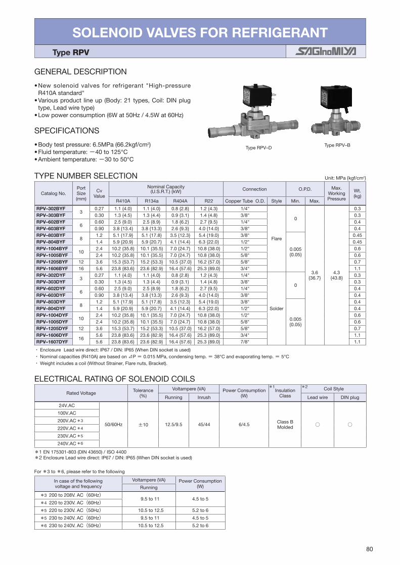
80
SOLENOID VALVES FOR REFRIGERANT Type RPV
GENERAL DESCRIPTION
•New solenoid valves for refrigerant "High-pressureR410Astandard"
•Variousproduct lineup(Body:21types,Coil:DINplugtype,Leadwiretype)
•Lowpowerconsumption(6Wat50Hz/4.5Wat60Hz)
TypeRPV–D TypeRPV–B
SPECIFICATIONS
•Bodytestpressure:6.5MPa(66.2kgf/cm2)•Fluidtemperature:−40to125°C•Ambienttemperature:−30to50°C
TYPE NUMBER SELECTION
・・Enclosure・Leadwiredirect:IP67/DIN:IP65(WhenDINsocketisused)・・Nominalcapacities(R410A)arebasedon⊿P =・0.015MPa,condensingtemp.=・38°Candevaporatingtemp.=・5°C・・Weightincludesacoil(WithoutStrainer,Flarenuts,Bracket).
Unit:MPakgf/cm2
CatalogNo.Port Size (mm)
Cv Value
NominalCapacity (U.S.R.T.)kW Connection O.P.D. Max.
WorkingPressure
Wt. (kg)
R410A R134a R404A R22 CopperTubeO.D. Style Min. Max.
RPV–302BYF3
0.27 1.14.0 1.14.0 0.82.8 1.24.3 1/4"
Flare
0
3.636.7
4.343.8
0.3RPV–303BYF 0.30 1.34.5 1.34.4 0.93.1 1.44.8 3/8" 0.3RPV–602BYF
60.60 2.59.0 2.58.9 1.86.2 2.79.5 1/4" 0.4
RPV–603BYF 0.90 3.813.4 3.813.3 2.69.3 4.014.0 3/8" 0.4RPV–803BYF
81.2 5.117.9 5.117.8 3.512.3 5.419.0 3/8"
0.0050.05
0.45RPV–804BYF 1.4 5.920.9 5.920.7 4.114.4 6.322.0 1/2" 0.45RPV–1004BYF
102.4 10.235.8 10.135.5 7.024.7 10.838.0 1/2" 0.6
RPV–1005BYF 2.4 10.235.8 10.135.5 7.024.7 10.838.0 5/8" 0.6RPV–1205BYF 12 3.6 15.353.7 15.253.3 10.537.0 16.257.0 5/8" 0.7RPV–1606BYF 16 5.6 23.883.6 23.682.9 16.457.6 25.389.0 3/4" 1.1RPV–302DYF
30.27 1.14.0 1.14.0 0.82.8 1.24.3 1/4"
Solder
0
0.3RPV–303DYF 0.30 1.34.5 1.34.4 0.93.1 1.44.8 3/8" 0.3RPV–602DYF
60.60 2.59.0 2.58.9 1.86.2 2.79.5 1/4" 0.4
RPV–603DYF 0.90 3.813.4 3.813.3 2.69.3 4.014.0 3/8" 0.4RPV–803DYF
81.2 5.117.9 5.117.8 3.512.3 5.419.0 3/8"
0.0050.05
0.4RPV–804DYF 1.4 5.920.9 5.920.7 4.114.4 6.322.0 1/2" 0.4RPV–1004DYF
102.4 10.235.8 10.135.5 7.024.7 10.838.0 1/2" 0.6
RPV–1005DYF 2.4 10.235.8 10.135.5 7.024.7 10.838.0 5/8" 0.6RPV–1205DYF 12 3.6 15.353.7 15.253.3 10.537.0 16.257.0 5/8" 0.7RPV–1606DYF
165.6 23.883.6 23.682.9 16.457.6 25.389.0 3/4" 1.1
RPV–1607DYF 5.6 23.883.6 23.682.9 16.457.6 25.389.0 7/8" 1.1
For*3to*6,pleaserefertothefollowing
ELECTRICALRATINGOFSOLENOIDCOILS
*1EN175301-803(DIN43650)/・ISO 4400*2EnclosureLeadwiredirect:IP67/DIN:IP65(WhenDINsocketisused)
RatedVoltage Tolerance(%)
Voltampere(VA) PowerConsumption(W)
InsulationClass
CoilStyle
Running Inrush Leadwire DINplug
24V.AC
50/60Hz ±10 12.5/9.5 45/44 6/4.5 ClassBMolded
100V.AC
200V.AC
220V.AC
230V.AC
240V.AC
*3
*4
*5
*6
Incaseofthefollowingvoltageandfrequency
Voltampere(VA) PowerConsumption(W)Running
*3 200to208V.AC(60Hz)9.5to11 4.5to5
*4 220to230V.AC(60Hz)
*5 220to230V.AC(50Hz) 10.5to12.5 5.2to6
*5 230to240V.AC(60Hz) 9.5to11 4.5to5
*6 230to240V.AC(50Hz) 10.5to12.5 5.2to6
*1 *2

81
12
4310
5
L
Hh
5
4310
Hh
L
12
M5×0.8Depth d
48
5
Hh
LM5×0.8Depth d
M5×0.8Depth d
M5×0.8Depth d
Thread Mounting Hole for GroundM4×0.7 Depth 2
Thread Mounting Hole for GroundM4×0.7 Depth 2
12
4310
5
Hh
LM5×0.8Depth d
Flow Direction
Flow Direction
48
Hh
L
548
5
Hh
L M5×0.8Depth d Flow Direction
Flow Direction
Thread Mounting Hole for GroundM4×0.7 Depth 2
DIMENSIONS
Unit:mm
CatalogNo.Unit:mm
L H h d
RPV–302BYF 64 67 12.5 12
RPV–303BYF 68 67 12.5 12
RPV–602BYF 71 74 15 12
RPV–603BYF 78 74 15 12
RPV–803BYF 84 75.5 15 14
RPV–804BYF 90 75.5 15 14
RPV–1004BYF 96 77 15.5 17
RPV–1005BYF 101 77 15.5 17
RPV–1205BYF 104 82 17 20
RPV–1606BYF 124 89 19 24
CatalogNo.Unit:mm
L H h d
RPV–302DYF 123 67 12.5 12
RPV–303DYF 123 67 12.5 12
RPV–602DYF 140 74 15 12
RPV–603DYF 138 74 15 12
RPV–803DYF 141 75.5 15 14
RPV–804DYF 139 75.5 15 14
RPV–1004DYF 158 77 15.5 17
RPV–1005DYF 168 77 15.5 17
RPV–1205DYF 171 82 17 20
RPV–1606DYF 196 89 19 24
RPV–1607DYF 196 89 19 24
TypeRPV–302BYF,303BYF TypeRPV–602BYFto804BYF
TypeRPV–1004BYFto1606BYF
TypeRPV–302DYF,303DYF TypeRPV–602DYFto804DYF
TypeRPV–1004DYFto1607DYF
OPTIONAL PARTS
DINsocketforDINplugcoilFlareNut
33
12
Gasket Fixing screw
(30)
30.5 Connector
42
PG 9

82
SOLENOID VALVES FOR REFRIGERANT Type REV & UEV
GENERAL DESCRIPTION
•TypeREV:Pilotoperated,2-way,Normallyclosedvalve. TypeUEV:Pilotoperated,2-way,Normallyopenedvalve.•Fornon-corrosiverefrigerant(liquidorgas)inrefrigeration, cooling,airconditioningsystems.•“Doubleplunger” constructionprovides reliableOn/Offaction.
•Compactmoldedcoilcommonlyfitsallvalvesizes.•Operatesinanyposition...canbeconvenientlylocatedinhorizontalorverticallinewithcoilontop.
•ManualOpeningStem ...OnFlangeconnectionmodels,suppliedas standard.OnFlareorSolder connectionmodels,supplieduponrequest.
TypeREV–D
TypeUEV–D
SPECIFICATIONS
•Fluidtemperature:−40to125°C(TypeREV) −40to120°C(TypeUEV)•Ambienttemperature:−30to40°C
・・Weightincludesacoil.・・EnclosureIP34(REV–W:Dripproofmodel)・・Nominalcapacities(R410A)arebasedon⊿P =・0.015MPa,condensingtemp.=・38°Candevaporatingtemp.=・5°C
Unit:MPakgf/cm2
CatalogNo.PortSize (mm)
Cv Value
NominalCapacity(U.S.R.T.)kw Connection O.P.D. Max.Working Pressure
Wt. (kg)R410A R134a R404A R22 CopperTube
O.D.SteelTube
O.D. Style Min. Max.
REV–703BXF 7 1.0 4.214.9 4.214.8 2.910.3 4.616 3/8"
−
Flare
0.0070.07
2.4525
2.9430
0.6
REV–1004BXF 10 2.0 8.529.8 8.429.6 5.920.6 9.132 1/2" 0.9
REV–1205BXF 12 3.5 14.952.2 14.751.8 10.236 15.956 5/8" 1.1
REV–1506BXF 15 5.3 22.579.1 22.378.5 15.554.5 23.984 3/4" 1.5
REV–1003GXF 10 2.0 8.529.8 8.429.6 5.920.6 9.132 3/8"
Rc
1.0
REV–1204GXF 12 3.5 14.952.2 14.751.8 10.236 15.956 1/2" 1.3
REV–1506GXF 15 5.3 22.579.1 22.378.5 15.554.5 23.984 3/4" 1.7
REV–703DXF 7 1.0 4.214.9 4.214.8 2.910.3 4.616 3/8"
Solder
0.5
REV–1004DXF 10 2.0 8.529.8 8.429.6 5.920.6 9.132 1/2" 0.8
REV–1205DXF 12 3.5 14.952.2 14.751.8 10.236 15.956 5/8" 0.9
REV–1506DXF 15 5.3 22.579.1 22.378.5 15.554.5 23.984 3/4" 1.1
REV–2007DXF
20 9.0 38.2134.3 37.9133.2 26.392.6 40.7143
7/8"
1.6REV–2010DXF 1"
REV–2011DXF 1–1/8"
REV–2511DXF
25 13.8 − 58.1204.3 40.4141.9 62.3219
1–1/8"
2.2REV–2512DXF 1–1/4"
REV–2513DXF 1–3/8"
REV–3213DXF
32 19.4 − 81.7287.2 56.7199.5 87.6308
1–3/8"
3.2REV–3214DXF 1–1/2"
REV–3215DXF 1–5/8"
REV–2006EXF 20 9.0 38.2134.3 37.9133.2 26.392.6 40.7143 7/8" 1–1/8" 3/4"
Flange
5.1
REV–2510EXF 25 13.8
−
58.1204.3 40.4141.9 62.3219 1" 1–1/2" 1" 7.7
REV–3212EXF 32 19.4 81.7287.2 56.7199.5 87.6308 1–1/4" 1–5/8" 1–1/4" 8.9
REV–4014EXF 40 32.0 134.7473.7 93.6329.1 144.5508 1–1/2" 2" 1–1/2" 10.8
REV–5020EXF 50 45.0 189.5666.2 131.6462.9 165.8583 2" 2–1/2" 2" 16.3
REV–6524EXF65 74.0 311.61095.5 216.5761.1 272.7959
2–1/2" 3" 2–1/2" 23.2
REV–6530EXF 3" 3–1/2" 3" 26.6
TYPE NUMBER SELECTIONTypeREV – Normallyclosedvalve(1)

83
Type RatedVoltage Tolerance(%)
Voltampere(VA) PowerConsumption(W)
Insulation ClassRunning Inrush
REV
24V.AC,100V.AC,110V.AC 200V.AC,220V.AC,240V.AC 50/60Hz +10
−1517/14 43/35 8/7
ClassB Molded
12V.DC,24V.DC 48V.DC,100V.DC − ±10 − − 10
UEV 24V.AC,100V.AC,110V.AC 200V.AC,220V.AC,240V.AC 50/60Hz +10
−1517/14 43/35 8/7
CatalogNo. PortSize (mm)
Cv Value
NominalCapacity(U.S.R.T.)kw Connection O.P.D. Max.Working Pressure
Wt. (kg)R410A R134a R404A R22 CopperTubeO.D. Style Min. Max.
REV–703BYF 7 1.0 4.214.9 4.214.8 2.910.3 4.616 3/8"
Flare
0.0070.07
2.4525
4.242
0.6
REV–1004BYF 10 2.0 8.529.8 8.429.6 5.920.6 9.132 1/2" 0.9
REV–1205BYF 12 3.5 14.952.2 14.751.8 10.236 15.956 5/8" 1.1
REV–1506BYF 15 5.3 22.579.1 22.378.5 15.554.5 23.984 3/4" 1.5
REV–1003GYF 10 2.0 8.529.8 8.429.6 5.920.6 9.132 3/8"
Rc
1.0
REV–1204GYF 12 3.5 14.952.2 14.751.8 10.236 15.956 1/2" 1.3
REV–1506GYF 15 5.3 22.579.1 22.378.5 15.554.5 23.984 3/4" 1.7
REV–703DYF 7 1.0 4.214.9 4.214.8 2.910.3 4.616 3/8"
Solder
0.5
REV–1004DYF 10 2.0 8.529.8 8.429.6 5.920.6 9.132 1/2" 0.8
REV–1205DYF 12 3.5 14.952.2 14.751.8 10.236 15.956 5/8" 0.9
REV–1506DYF 15 5.3 22.579.1 22.378.5 15.554.5 23.984 3/4" 1.1
REV–2007DYF
20 9.0 38.2134.3 37.9133.2 26.392.6 40.7143
7/8"
1.6REV–2010DYF 1"
REV–2011DYF 1–1/8"
・・Weightincludesacoil.・・EnclosureIP34(REV–W:Dripproofmodel)・・Nominalcapacities(R410A)arebasedon⊿P =・0.015MPa,condensingtemp.=・38°Candevaporatingtemp.=・5°C
Unit:MPakgf/cm2
TYPE NUMBER SELECTIONTypeREV – Normallyclosedvalve(2)
CatalogNo. PortSize (mm)
Cv Value
NominalCapacity(U.S.R.T.)kw Connection O.P.D. Max.Working Pressure
Wt. (kg)R410A R134a R404A R22 CopperTubeO.D. Style Min. Max.
UEV–1004BXF 10 2.0 8.529.8 8.429.6 5.920.6 9.132 1/2"
Flare
0.0070.07
1.9620
2.9430
0.9
UEV–1205BXF 12 3.5 14.952.2 14.751.8 10.236 15.956 5/8" 1.1
UEV–1506BXF 15 5.3 22.579.1 22.378.5 15.554.5 23.984 3/4" 1.5
UEV–1003GXF 10 2.0 8.529.8 8.429.6 5.920.6 9.132 3/8"
Rc
1.0
UEV–1204GXF 12 3.5 14.952.2 14.751.8 10.236 15.956 1/2" 1.3
UEV–1506GXF 15 5.3 22.579.1 22.378.5 15.554.5 23.984 3/4" 1.7
UEV–2010GXF 20 9.0 38.2134.3 37.9133.2 26.392.6 40.7143 1" 1.9
UEV–1004DXF 10 2.0 8.529.8 8.429.6 5.920.6 9.132 1/2"
Solder
0.8
UEV–1205DXF 12 3.5 14.952.2 14.751.8 10.236 15.956 5/8" 0.9
UEV–1506DXF 15 5.3 22.579.1 22.378.5 15.554.5 23.984 3/4" 1.1
UEV–2007DXF
20 9.0 38.2134.3 37.9133.2 26.392.6 40.7143
7/8"
1.6UEV–2010DXF 1"
UEV–2011DXF 1–1/8"
・・Weightincludesacoil.・・EnclosureIP34(UEV–W:Dripproofmodel)・・Nominalcapacities(R410A)arebasedon⊿P =・0.015MPa,condensingtemp.=・38°Candevaporatingtemp.=・5°C
Unit:MPakgf/cm2
TYPE NUMBER SELECTIONTypeUEV – Normallyopenedvalve
Current(A)= Voltampere/RatedVoltage
ELECTRICALRATINGOFSOLENOIDCOILS
*IECcompliance
*

84
DIMENSIONS
L
φDK
M14 ×1
G1/2280
Hh
K
280
φD
L
hH
L
M20×1(2007D~3215D)
M14×1(703D~1506D)
E
G1/2
280
φD
K
Hh
G1/2
280
L
hH
KφD
TypeREV–B,UEV–BX TypeREV–G,UEV–GX
TypeREV–D,UEV–DX
TypeREV–EX
Unit:mm
CatalogNo.Unit:mm
L H h E φD K
REV–
703BX [Y] 90 70 [73] 19
−
48 44
1004BX [Y] 105 88 [90] 21
1205BX [Y] 115 90 [92] 22
1506BX [Y] 135 96 [99] 25
1003GX [Y] 65 89 [91] 20
1204GX [Y] 75 94 [96] 21
1506GX [Y] 85 99 [102] 24
703DX [Y] 150 70 [73] 19 10
1004DX [Y] 160 88 [90] 21 13
1205DX [Y] 180 90 [92] 22 16
1506DX [Y] 190 96 [99] 25 19
2007DX [Y]
230 112 [116] 29 202010DX [Y]
2011DX [Y]
2511DX
240 123 31 232512DX
2513DX
3213DX
260 126 35 263214DX
3215DX
2006EX 95 112 73
−
2510EX 110 123 78
3212EX 120 126 87
4014EX 130 133 92
5020EX 170 149 115
6524EX 200169 129
6530EX 210
UEV–
1004BX 105 108 21
−
48 44
1205BX 115 110 22
1506BX 135 116 25
1003GX 65 109 20
1204GX 75 112 21
1506GX 85 119 24
2010GX 100 133 33
1004DX 160 108 21 13
1205DX 180 110 22 16
1506DX 190 116 25 19
2007DX
230 132 29 202010DX
2011DX

85
SOLENOID VALVES FOR WATER Type WEV
GENERAL DESCRIPTION
•Pilotoperated,2-way,normallyclosedvalve.•Forwaterinrefrigeration,cooling,airconditioningsystems,andgeneralindustrialplant.
•Valves for non-corrosive brine are available. To order,specifycatalogNo.with“B”
Example:WEV–1504GLWforwater WEV–1504GLBfornon-corrosivebrine,warmwater•Compactmoldedcoilcommonlyfitsallvalvesizes.•Operates inanyposition ...canbeconveniently located inhorizontalorverticallinewithcoilontop.
TypeWEV–G
TypeWEV–F
DIMENSIONS
φDK
G1/2HHh
h
L
L
φDK
G1/2
280280
TypeWEV–G TypeWEV–F
Unit:mm
RatedVoltage Tolerance (%)
Voltampere(VA) PowerConsumption (W) InsulationClass
Running Inrush
24V.AC,100V.AC,110V.AC 200V.AC,220V.AC,240V.AC 50/60Hz
±10
18/14 57/47 9/8
ClassBMolded12V.DC,24V.DC 48V.DC,100V.DC — — — 11
Specifyvoltage&frequencywhenorder.
ELECTRICALRATINGOFSOLENOIDCOILS
*IECcompliance
*
CatalogNo.Unit:mm
L H h φD K
WEV–
1504GL 65 82 19
48 44
2006GL 80 86 25
2510GL 90 91 29
3212GL 105 97 36
4014GL 120 103 47
5020GL 140 126 55
1504FL 105 82 48
2006FL 115 86 50
2510FL 125 91 63
3212FL 140 97 68
4014FL 150 103 70
5020FL 160 126 78
6524FL 200 138 88
8030FL 240 152 93
TYPE NUMBER SELECTION (SPECIFICATIONS)
*・Withoutcompanionflange(Weightwithoutcompanionflangeandbolts) ・・O.P.D.:OperatingPressureDifferential(bywaterpressure) ・・Ambienttemperature:−30to50°C,allowablefluidtemperature:0to60°C(TypeW),−35to90°C(TypeB) ・・Apparentpower:16VA ・・Useofastrainer80to100meshatthevalveinletisrecommended.・・Weightincludesacoil・・EnclosureIP34(WEV–W:Dripproofmodel)
Unit:MPakgf/cm2
CatalogNo. PortSize (mm)
Cv Value
Connection O.P.D. Max. Working Pressure
Wt. (kg)Type Model Fluid SteelTubeO.D. Style Min. Max.
WEV–
1504GL
W (Water)
B
(glycol, WarmWater)
15 4.3 1/2"
Rc0.0150.15
0.9810
0.9810
0.6
2006GL 20 7.8 3/4" 0.8
2510GL 25 10.4 1" 1.1
3212GL 32 17.6 1–1/4" 1.6
4014GL 40 26 1–1/2" 2.4
5020GL 50 42 2" 0.030.3 3.6
1504FL 15 4.3 1/2"
Flange (RoundType)
0.0150.15
2.0
2006FL 20 7.8 3/4" 2.6
2510FL 25 10.4 1" 3.7
3212FL 32 17.6 1–1/4" 5.0
4014FL 40 26 1–1/2" 5.7
5020FL 50 42 2"0.030.3
7.7
6524FL 65 65 2–1/2" 12.8
8030FL 80 100 3" 16.5
*

86
GENERAL DESCRIPTION
•Bi-flow controlling applicable. Developed for thepurposeof simplificationof complicated refrigerationcircuit.
•Notonly for ordinary refrigeration circuit, suitable forflowchangeofheatexchangeronmultitypeheatpumpairconditioner.
DIMENSIONSφ48
280
LB
A
hH
Hh
280
φ48
L
BA
34
34
EquivalentcircuitoftypeBPVBi-flowSolenoidValveisasfollow.
FunctionofBi-flowSolenoidValve
S
S
SA B BA
Check Valve
Standard Solenoid Valve
Type BPV Solenoid Valve
Unit:mm
TypeBPV–A
figure1
BI-FLOW SOLENOID VALVESHigh Volume OEM Item
Type BPV
High Volume OEM Item
SPECIFICATIONS
•Fluidtemperature:− 30to120°C•Ambienttemperature:− 20to60°C
CatalogNo. FluidPortSize (mm)
Cv Value
BleedCvValue B→ A
NominalCapacity(U.S.R.T.)kw ConnectionOperationPressure
Differential(MPa)
Max.WorkingPressure (MPa)
Wt. (kg)
R410A R134a R404A R22 Style CopperTubeO.D. Min. Max.
BPV–
803ADY
Refrigerant
7.8 1.5 LessThan0.01 6.422.4 6.322.2 4.415.4 6.823.8
Solder
3/8"0.01
2 4.2
0.33
1204ADY 11 2.9LessThan0.013
12.343.3 12.242.9 8.529.8 13.146.0 1/2" 0.46
1706ADY 17 6.6 2898.5 27.897.7 19.367.98 29.8104.7 3/4" 0.015 0.86
TYPE NUMBER SELECTION
*・Gaslineonly
・・BleedingwillbehappenwhenpressureofBsideishigherthanAside.
・・Weightincludesacoil
* *
PortSize (mm) RatedVoltage Tolerance
(%)Voltampere(VA) PowerConsumption
(W) InsulationClassRunning Inrush
7.8,11 100V.AC,200V.AC 220V.AC,240V.AC 50/60Hz ±10
12/10 36/30 6/5 ClassB Molded17 17/14 51/42 7.5/6
ELECTRICALRATINGOFSOLENOIDCOILS
・・Current(A)=Voltampere/RatedVoltage *IECcompliance
*
CatalogNo.Unit:mm
FormL H h
BPV–
803ADY 48 76 48
figure11204ADY 61 69 60
1706ADY 91 85 82

87
3-WAY SOLENOID VALVES Type IEV
GENERAL DESCRIPTION
•Fornon-corrosiverefrigerant(gas)inrefrigerationunitsorair.
•Pilot operated, 3-wayDistributing valve andSelectorvalve.
TypeIEV–B TypeIEV–C
Unit:MPakgf/cm2
OPERATIONTypeIEV–B
Energized : A→Cnon Energized : A→B
TypeIEV–C
Energized : B→Anon Energized : A→C
DIMENSIONSTypeIEV–B1505DXF(B2007DXF)
44 90(109)
139(158)
600
193(213)
85(92)
80(99)
22
16(20)
φ16.13(φ22.47)
109(116)
TypeIEV–B3211DXFtoB3213DXF,C3211DXFtoC3213DXF
12057
210
22
44 280
G1/2
2-M6×10
271
157
23
40108
114
Unit:mm
TYPE NUMBER SELECTION (SPECIFICATIONS)
*・Nominalcapacitiesarebasedon⊿P =0.015MPa,condensingtemp.=38°Candevaporatingtemp.=5°C.
・・O.P.D.:OperatingPressureDifferential(byairpressure)・・Weightincludesacoil
CatalogNo.Port Size (mm)
Cv Value
NominalCapacity (RefrigerantsinLiquid)(U.S.R.T.)
Connection O.P.D.Max.
Working Press.
Body Test Press.
Fluid Temp. (°C)
Ambient Temp. (°C)
Operation Wt. (kg)
R134a R22Copper pipe (O.D.)
Style Min. Max.
IEV–B1505DXF 18 6.3 16 20 5/8"
Solder
0.495.0
2.2522.9
2.9430
4.4145
−20 to
120
−20 to 50
branched
0.95
IEV–B2007DXF 20 9.0 23 29 7/8" 1.0
IEV–B3211DXF
30 25
65 79
1–1/8"
0.293.0
2.0621
−20 to
1252.6
IEV–B3212DXF 1–1/4"
IEV–B3213DXF 1–3/8"
IEV–C3211DXF
42 36
1–1/8"
switchedIEV–C3212DXF 1–1/4"
IEV–C3213DXF 1–3/8"
*
Current(A)= Voltampere/RatedVoltage
ELECTRICALRATINGOFSOLENOIDCOILS
*IECcompliance
PortSize(mm) RatedVoltage Tolerance
(%)
Voltampere(VA) PowerConsumption(W) InsulationClass
Running Inrush
18,20 100V.AC,110V.AC200V.AC,220V.AC 50/60Hz ±10
11/9 33/27 6/5ClassBMolded
30 16/13 40/33 8/7
*

88
4-WAY REVERSING VALVESHigh Volume OEM Item (Type STF)
Type STF
GENERAL DESCRIPTION
•Pilot operated4-way reversing valves are suitable forheatpumpapplicationsonunitary, split systemandwindowtypeairconditioners,etc.
•4-waypilotvalveadoptionhasanadvantageonreliablechangeoveroperations.
•Designed to lower theminimumoperatingpressuredifferencebetweenhighand lowside.Pressuredropandvalveleakageareminimized.
SPECIFICATIONS
•Max.workingpressure:4.2MPa42.8kgf/cm2 (TypeSTF–H****) 4.15MPa42.3kgf/cm2 (TypeSTF–****G)•Ambienttemperature:− 20to55°C•Allowablefluidtemperature:− 20to120°C (STF–H0104toSTF–1511G) − 20to130°C (STF–2023Gto6001G)•Ambienthumidity:Lessthan95%R.H.
markapplicable(availableuponrequest)
ULlisted(availableuponrequest)
TypeSTF–H01,H02 TypeSTF–H04,H07
TypeSTF–25,30,40,50,60
・・O.P.D.:OperatingPressureDifferential(withair)
High Volume OEM Item
CatalogNo.PortSize(mm)
Capacity(R410A) O.P.D.(MPa)kgf/cm2 Connection(O.D.) Wt.(kg)(kW) (U.S.R.T.) Max. Min. Discharge Suction&Coils
STF–H0104 8 1.8 to 6.4 0.51 to 1.82
3.131.6 0.33.1
5/16" 3/8" 0.2
STF–H0202 11.1 2.0 to 11.4 0.57 to 3.24 3/8" 1/2" 0.32
STF–H0301 11.5 5.3 to 14.6 1.50 to 4.15
1/2"
5/8" 0.37
STF–H0404 16 8.3 to 33 2.36 to 9.393/4"
0.77
STF–H0601 18.1 8.4 to 45 2.39 to 12.8 0.87
STF–H0712 20 21 to 53 5.97 to 15.03/4" 7/8"
1.2
STF–H0901 21.3 21 to 68.5 5.97 to 19.5 1.23
STF–1511G 23 39 to 59 11.1 to 16.77/8" 1–1/8" 1.55
STF–2023G 24 39 to 74 11.1 to 21.0
STF–2501G 28 52 to 94 14.8 to 26.7 1" 1–1/4" 3.4
STF–3001G 34 65 to 124 18.5 to 35.2 1–1/4" 1–1/2" 4.7
STF–4001G 40 115 to 188 32.7 to 53.41–1/2"
1–3/4" 9.1
STF–5001G 50 145 to 235 41.2 to 66.8 2–1/8" 9.4
STF–6001G 60 230 to 360 65.4 to 102 I.D.1–5/8" 2–5/8" 20.0
TYPE NUMBER SELECTION
TypeSTF–H06,H09
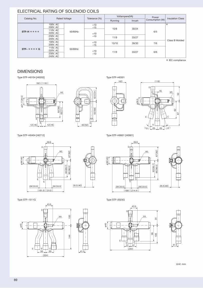
89
DIMENSIONS
(92)[(118)]
12[16] 12[16]
φ21.7[26.5]
50[59]
62[71]
62[68]
42.5[51]
42[52]D
C
S
E
M5 M5
M5 M5
M4 M4
16
25 25
(42)
φ26.5
8762
52
(118)
D
S
E C
(15°)(15°)
29[33.5]29[33.5]
95[98.5]
(181.5)[(212)]
83[85.7]
67[82]
39.6
φ36[45]
35.5[40]
D
ES
C
39.6
67[82]
95[98.5]
83[85.7]
(188)[(214.4)]
φ36[45]
29[33.5] 29[33.5] 35.5[40]
ES
C
D
(224)
φ45
43.5
144
100
50 50 41.5
D
φ45
(244)37 37
43.5
96
109
91
S
D
EC
E S C
41.5
TypeSTF–H0104[H0202]
TypeSTF–H0404[H0712]
TypeSTF–H0301
TypeSTF–H0601[H0901]
TypeSTF–1511G TypeSTF–2023G
Unit:mm
*IECcompliance
ELECTRICALRATINGOFSOLENOIDCOILS
CatalogNo. RatedVoltage Tolerance(%)Voltampere(VA) Power
Consumption(W) InsulationClassRunning Inrush
STF–H****
100V.AC200V.AC
50/60Hz
+10–15 10/8 30/24
6/5
ClassBMolded
110V.AC220V.AC +10
–10230V.AC240V.AC 11/9 33/27
STF–**** G
100V.AC200V.AC
50/60Hz
+10–15
13/10 39/30 7/6
110V.AC220V.AC +10
–1011/9 33/27 6/6
230V.AC240V.AC
*

90
D
E SC
5858
30
φ88166
200
149
169 *
136
81
63(414)
*STF‒5001G: 202
226
230
40
φ66120
142
120
145
121
39
76
D
ES
C
4949(347)
40
260
300
220
E
S
C
(526)75 75
184
240
82.5
D
33103
(195.5)
158
φ116
M4
M4
M4
TypeSTF–3001G
TypeSTF–4001G,–5001G
TypeSTF–6001G
Unit:mm
FLOWRATE(Capacity)
STF-1501GSTF-H0712
STF-H0901
STF-H0601STF-H0404
0.001 0.005 0.01 0.04
1
5
10
50
100
500
STF-5001GSTF-4001G
STF-3001G
STF-2501GSTF-2023G
STF-H0301STF-H0202
STF-H0104
Capacity(kW)
Suction Pressure Drop MPa
Refrigerant: R410AKw
USRT
0.1 0.5 1 5 PSI
MPa
1
0.5
0.3
2
10
15
4
6
8
20
40
30
50
100
STF-6001G
STF-5001GSTF-4001G
STF-3001G
STF-2501G
STF-1501G
STF-2023G
STF-H0712
STF-H0901
STF-H0601STF-H0404
STF-H0301STF-H0202
STF-H0104
500
100
50
10
5
1
Capacity(kW)
Refrigerant: R22,R407C
STF-6001GKw
USRT
0.001 0.005 0.01 0.04
Suction Pressure Drop MPa0.1 0.5 1 5 PSI
MPa
1
0.5
0.3
2
10
15
4
6
8
20
40
30
50
100
*・FlowRateConditionsCondensingtemp.:38°C Evaporatortemp.:5°C Superheattemp.:5°C
D
E SC
5858
30
φ88166
200
149
169 *
136
81
63(414)
*STF‒5001G: 202
226
230
40
φ66120
142
120
145
121
39
76
D
ES
C
4949(347)
40
260
300
220
E
S
C
(526)75 75
184
240
82.5
D
33
103(195.5)
158
φ116
M4
M4
M4
TypeSTF–2501G
D
ES
C
45 45
(311)(76)
111
131117
φ61
M4

91
MOTORIZED BALL VALVES Type MJV
GENERAL DESCRIPTION
•ProportionalControlvalveforhotorchilledwater,industrialwaterandsteamcircuit.
•Compact&Lightweightdesign,manual operation isalsoavailable.
•VarioustypesofwatersupplyEquipments•AirHandlingUnits•IceStorageUnits
TypeMJV
TYPE NUMBER SELECTIONTwo-wayValve
CatalogNo. ConnectionRc(O.D.) CvValue
Max.OperationPress.Differential
(MPa)
ConnectionFasteningTorque
(N・m)
Dimension Wt.(kg)Type Model InputSignal H L D
MJV–
1504GQ1
70(Resistance0to135Ω)
71(4to20mA)
72(1to5VDC)
73(0to10VDC)
1/2"
1
1
34.3 152 56 32 1.51504GQ2 2
1504G 3.5
2006G 3/4" 6.5 49 155 69 42 1.7
2510G 1" 12 58.8 159 82 50 1.9
3212G 1–1/4" 20 0.8 78.5 165 97 60 2.6
4014G 1–1/2" 30 0.6 83.4 178 106 71 3.2
5020G 2" 45 0.4 98.1 185 128 84 4.6
Two-wayValveforSteamCatalogNo. Connection
Rc(O.D.) CvValueMax.OperationPress.Differential
(MPa)
ConnectionFasteningTorque
(N・m)
Dimension Wt.(kg)Type Model InputSignal H L D
MJV–
H1504GQ1
70(Resistance0to135Ω)71(4to20mA)72(1to5VDC)73(0to10VDC)
1/2"
1
1
34.3 202 56 32 1.8H1504GQ2 2
H1504G 3.5
H2006G 3/4" 6.5 49 205 69 42 2.0
H2510G 1" 12 58.8 209 82 50 2.2
SPECIFICATIONSValveType
ItemTwo-wayValve Two-wayValveforSteam Three-wayValve
WaterTestPressure 1.6MPa
AirTightPressure 1.6MPa
Max.WorkingPressure 1.6MPa(0.2MPaforSteam) 1.6MPa(0.5MPaforSteam) 1.6MPa
Fluid Non-corrosivewaterandSteam Non-corrosivewater
FluidTemperature 0to120°C 0to160°C 0to90°C
FlowCharacteristics EqualPercentage CorrectedLinear
ValveLeakage Cv:0.1%orless −Material Body:BronzeCasting,SeatRing:Fluoro-resin,O-ring:Fluororubber,Spindle:StainlessSteel,Plug:StainlessSteel
PowerSupplyVoltage 24V.AC±10%,50/60Hz
Max.powerConsumption 12VA
HousingConstruction Rain-Proof(JISC0920IP53)
AmbientTemperature OperatingTemp.:−10to50°C,StorageTemp.:−20to70°C
Timing Approx.52sec.
ResistanceInput 0to135ΩCurrentInput DC 4to20mA(InputImpedance250Ω)
VoltageInput DC 1to5V(InputImpedance100kΩ),DC0to10V(InputImpedance250kΩ)
Material Case:PPSResin,Cover:ABSResin
ManualOperation Yes
FlowDisplay O:Open,S:Close O:Open(C→A),S:Close(C→A)
MovementofValve InputSignal135Ω・4mA・1V・0V:Close InputSignal135Ω・4mA・1V・0V:Close(C→A)
VALV
EPART
MO
TOR
PA
RT
INP
UT
SIG
NA
L

92
MountingPosition
Mountingpositionshouldbeinthebelowrange.
Flow
Opening Indicator
Label
Shaft forManual Operation
Clutch Release Buttonfor Manual Operation
Flow Direction display
0.3mm Cab tire code
(130)
(100)(5)
116
1000
2-Rc
D L
(11)
(H)
906
S
Opening Indicator
Label
Shaft forManual Operation
Clutch Release Buttonfor Manual Operation
Flow Direction display
0.3mm Cab tire code
(130)
(100)(5)
116
1000
3-Rc
D L
(11)
(H1)
(H2)(B) (C)
Flow
Mixed(A)
Flow
906
S
Flow
Opening Indicator
Label
Shaft forManual Operation
Clutch Release Buttonfor Manual Operation
Flow Direction display
0.3mm Cab tire code
(130)
(100)(5)
116
1000
2-Rc
D L
(11)
(H)
906
S
Opening Indicator : O...Open, S...Close
90°90° 90
°
90°
Two-wayValve
Three-wayValve
Two-wayValveforSteam
DIMENSIONS
ManualOperation
•UseaspanneratManualOperationshaft(Torque:3N・m),withpushingaClutchReleaseButton.Manualoperationcanbecarriedoutbyrotatingtheshaft.Don'toperateinenergizedpositionforthesafty.--pleasedonotoperateitbyanymeans.
Three-wayValve
Unit:mm
Resistance Input Current Input Voltage Input
(Blue)COM.
(Brown)0 to 135Ω
(Black)
(Red)
Input
Supply Voltage 24V.AC
(Blue)COM.
(Brown)4 to 20mA
(Black)
(Red)
Input
Supply Voltage 24V.AC
(Blue)COM.
(Brown)1 to 5V , 0 to 10V
(Black)
(Red)
Input
Supply Voltage 24V.AC
WIRING
CatalogNo. ConnectionRc(O.D.) CvValue
Max.OperationPress.Differential
(MPa)
ConnectionFasteningTorque
(N・m)
Dimension Wt.(kg)Type Model InputSignal H1 H2 H2 L
MJV–
M1504G 70(Resistance0to135Ω)
71(4to20mA)
72(1to5VDC)
73(0to10VDC)
1/2" 3.5
0.1
34.3 152 30 56 32 1.6
M2006G 3/4" 6.5 49 155 37 69 42 1.8
M2510G 1" 12 58.8 159 44 82 50 2.1
M3212G 1–1/4" 20 78.5 165 51 97 60 2.8
M4014G 1–1/2" 30 83.4 178 57 106 71 3.5
M5020G 2" 45 98.1 185 67 128 84 5.0

93
DAMPER & VALVE MOTOR ACTUATORS Type EGK & WGK
GENERAL DESCRIPTION
•SeriesGKmotor actuator canprovideOn-Off, propor-tionalor floatingcontrolofdamper,valveorothercon-trollingdevices.
•Balancingrelaywithoutcontactcausesnoburn-out.•TypeEGKisfordamper. TypeWGKisforvalve.
Powerrequirement: 24V.AC±10%,50/60Hz
Max.powerconsumption:21VA(withoutspringreturnaction) 24VA(withspringreturnaction)
Inputsignal: resistance 0to135Ω Current 4to20mA.DC
(InputImpedance250Ω) Voltage 1to5V.DC
(InputImpedance100kΩ)
Type:EGK Torque: 12.2N·m1.25kg·m
(withoutspringreturnaction) 3.9N·m0.4kg·m (withspringreturnaction)
Rotationangle:90to270° (withoutspringreturnaction) 90to160° (withspringreturnaction) DeliverySetting90°
Timing: 80sec/160° Ambienttemp.: − 20to55°C
(withoutspringreturnaction) − 10to55°C (withspringreturnaction)
Weight: 4.3kg (withoutspringreturnaction) 6.1kg (withspringreturnaction)
Type:WGK Thrust: 1220N125kgf
(withoutspringreturnaction) 390N40kgf (withspringreturnaction)
Stroke: 14to50mm (withoutspringreturnaction) 14to30mm (withspringreturnaction) DeliverySetting20mm
Timing: 80sec/stroke25mm Ambienttemp.: − 20to55°C
(withoutspringreturnaction) − 10to55°C (withspringreturnaction)
Weight: 5kg (withoutspringreturnaction) 6.7kg (withspringreturnaction)
Type EGK
TypeWGK
DAMPER MOTOR SELECTION
*・1.ThemotoractuateswithOn-Offorfloatingsignalfromsensor. *・2.Themotoractuateswithproportionalsignalfromelectronicsensor(Example:TypeRBEControlUnit). *・3.Themotoractuateswiththesignalbetween0and135Ωfromelectricsensor(Example:TypePWSThermostat). *・4.SpringReturnTypeissodesignedthatactuatorshaftreturnstosafesideoncurrentfailure.・・Auxiliarypotentiometeristoprovidethesignalbetween0and135Ωinaccordancewithmotorangularrotationforoutput.・・AuxiliaryswitchprovidesthecontactsignalofS.P.D.T.foroutput.・・Enclosure:IP62
VALVEMOTORSELECTION
TYPE NUMBER SELECTION (SPECIFICATIONS)
FunctionModel
On-Off/FloatingControl WithoutPositioningBalanceRelay WithPositioningBalanceRelay WithPositioningBalanceRelay
On-Off/Floating On-OffServo ResistanceInput CurrentInput VoltageInput
Standard WGK–N500A WGK–N600A/S WGK–N700A/S WGK–N701A/S WGK–N702A/S
WithAuxiliaryPotentiometer − WGK–N610A/S WGK–N710A/S WGK–N711A/S WGK–N712A/S
WithAuxiliarySwitch WGK–N520A WGK–N620A/S WGK–N720A/S WGK–N721A/S WGK–N722A/S
FunctionModel
On-Off/FloatingControl WithoutPositioningBalanceRelay WithPositioningBalanceRelay WithPositioningBalanceRelay
On-Off/Floating On-OffServo ResistanceInput CurrentInput VoltageInput
Standard EGK–N500A EGK–N600A/S EGK–N700A/S EGK–N701A/S EGK–N702A/S
WithAuxiliaryPotentiometer − EGK–N610A/S EGK–N710A/S EGK–N711A/S EGK–N712A/S
WithAuxiliarySwitch EGK–N520A EGK–N620A/S EGK–N720A/S EGK–N721A/S EGK–N722A/S
*4*3*2
*1 *2 *3 *4
*1

94
INTERNALWIRINGS
•Checkpowersupplytobe24V.AC±10%.•Wiring istobebasedonthetechnicalstandardofelectrical installation.Beassuredtousecoveredcopperwire largerthan1.2mmdia.
•Terminalwiringshouldbeconductedwithflexiblewireofadequatelengthtopreventwiredisconnectionfromslightmoveofthemotor.
24V. AC
Input Signal4 to 20 mA. DC
COM
AuxiliaryPotentiometer
Auxiliary Switch
1 to 5 V. DC
Proportional Controller(0 to 135Ω)
da
e
g
f b
c
8
91
3
7
6
24V. AC
da
e
g
f b
c
9
81
2
7
4
6
10
11
5
10
11
5
S
RV.I
-
+
+
On-Off orFloatingController
On-OffServo Signal
FeedbackResistance
24V. AC
24V. AC
9
8c
b 76
ad
da
ef
b c
9
8
2
43
1
7
6
EGK–N500A,WGK–N500A
EGK–N600A/S,WGK–N600A/S
Type EGK–N…A Type EGK–N…S
EGK–N700A/S,WGK–N700A/S
EGK–N701A/S,N702A/S,WGK–N701A/S,N702A/S
a:UpperLimitSwitch
b:LowerLimitSwitch
c:Cam
d:CondenserMotor
e:FeedbackPotentiometer
f:SpringReturnReleasingMagnet
g:BalanceRelay
Terminals
MotorInternalWiring
MotorExternalWiring
SpringReturnTypeOnly
EGK–N 1 A/SWGK–N 1 A/S
EGK–N 2 A/SWGK–N 2 A/S
DIMENSIONS
122
130
8.5
210
9510
3634
150
130
φ34.5
150
19817127
122 187
322
210
9510
112
18780.5
2-φ27 with Plastic Cap
2-φ27 with Plastic Cap
2-φ11 Mounting Hole
Hole for adjusting Rotation
Hole for adjusting Stroke
122
130
8.5
210
9510
3634
150
25980.5
2-φ27 with Plastic Cap
2-φ11 Mounting Hole
Hole for adjusting Rotation
Valve OpeningPosition Indicator
130
φ34.5
150
27027
122187
322
210
9510
112
2-φ27 with Plastic Cap
Hole for adjusting Stroke
Valve OpeningPosition Indicator
TypeWGK–N…STypeWGK–N…A

95
2-WAY & 3-WAY CONTROL VALVES Type NVK
GENERAL DESCRIPTION
•Type NVK contro l va lves are accompanied bySaginomiya typeWGKmotor for twoposition (On-Off),floatingorproportionalcontrol.
•Forusewithloworhighpressurehotandchilledwaterornon-corrosivefluid.
•NVK...2-wayvalve(singleseatedtype) NVK–W...2-wayvalve(doubleseatedtype) NVK–M...3-wayvalve(mixingvalve)
•Widemodelselectionavailableforvariousapplications.•V-portplugprovidesalmostlinearflowcharacteristic.
TYPE NUMBER SELECTION (SPECIFICATIONS)
TypeNVK – 2-wayvalve
TypeNVK–M–3-wayvalve
TypeNVK–GTypeNVK–F
Model
ItemNVK—M**** GL NVK—M**** FL
Connection Rc Flange(JIS10K)
Fluid Non-corrosiveWaterforAirconditioning
Max.WorkingPress. 0.98MPa10kgf/cm2
FluidTemp.(°C) 0to200
FlowCharacteristic EqualPercentage
MaterialofBody CAC406 FC200
MaterialofPlug SCS14
MaterialofSeatRing SUS316
MaterialofStem SUS304
Model
ItemNVK—**** GL NVK—**** FL NVK—W**** FL
Connection Rc Flange(JIS10K) Flange(JIS10K)
Fluid Non-corrosiveWaterandSteam
Max.WorkingPress. 0.98MPa10kgf/cm2 0.98MPa10kgf/cm2
FluidTemp.(°C) 0to200 0to200
FlowCharacteristic EqualPercentage
MaterialofBody CAC406 FC200 FC200
MaterialofPlug SCS14
MaterialofSeatRing SUS316
MaterialofStem SUS304

96
TypeNVK–2-wayvalve
・・Cv...Flow(L/min)passingthroughthevalveatfullopeningwhenwatertemperatureis15°Candpressure differenceacrossthevalveis0.00048MPa0.0049kgf/cm2
・・Thedimensionvaluebracketedoffby()shows"h2"valuedueto"h2"valuebeingbiggerthantheoneof"h".
L
hH
Hh
h2
L
M8×1
90
90
M8×1Stroke
Stroke
DIMENSIONS
Unit:mm
TypeNVK–G
TypeNVK–F,WF
CatalogNo.Port Size (mm)
Connection CvValue
Stroke (mm)
CloseoffRatingMPakgf/cm2 Dimensions(mm) Wt. (kg)TubeO.D. Style WGK–N*A WGK–N*S WGK–N*L L H h(h2)
NVK–
1504GL@1
15 1/2"
Rc
1
20
0.9810
0.9810
0.9810
80 43 280.91504GL@2 2.5
1504GL 5 0.666.7
2006GL 20 3/4" 8 0.383.9 0.95
2510GL 25 1" 12 0.242.4 90 48 29 1.2
3212GL 32 1–1/4" 20 0.959.7 0.141.4 105 50 30 1.6
4014GL 40 1–1/2" 30 0.616.2 0.090.9 120 60 35 2.4
5020GL 50 2" 45 0.404.1 0.050.5 0.676.8 140 68 46 3.6
6524FL 65 2–1/2"Flange (JIS10K)
7030
0.282.9 0.0440.45 0.484.9 276 125 87.5 19.9
8030FL 80 3" 110 0.191.9 0.0280.29 0.313.2 298 149 92.5 25
10040FL 100 4" 180 40 0.121.2 − 0.22 352 169 105 36
NVK–W
4014FL@140 1–1/2"
Flange (JIS10K)
20
20
0.9810
0.9810
−
222 110 70 10.54014FL 30
5020FL 50 2" 45 254 114 (80) 13.5
6524FL 65 2–1/2" 7030
0.818.3 276 129 (96) 18
8030FL 80 3" 110 0.666.7 298 156 (115) 28.5
10040FL 100 4" 180
40
−
352 187 (150) 46.5
12550FL 125 5" 260 403 208 (153) 63.3
15060FL 150 6" 380 451 225 (170) 90.6
20080FL 200 8" 63045
0.697 543 278 (212) 167
250100FL 250 10" 960 0.495 673 319 (232) 251
Hh
h2
L
M8×1
90
Stroke

97
TypeNVK3-wayvalve(usedasamixingvalve)
M8×1
L
hH
90
StrokeStroke
M8×1
hH
90
L
・・Cv...Flow(L/min)passingthroughthevalveatfullopeningwhenwatertemperatureis15°Candpressure differenceacrossthevalveis0.00048MPa0.0049kgf/cm2
DIMENSIONS
Unit:mm
TypeNVK–MG
TypeNVK–MF
CatalogNo.Port Size (mm)
Connection CvValue
Stroke (mm)
CloseoffRatingMPakgf/cm2 Dimension(mm) Wt. (kg)TubeO.D. Style WGK–N*A WGK–N*S WGK–N*L L H h
NVK–M
1504GL 15 1/2"
Rc
5
20
0.98100.383.9
0.9810
80 2972 1.1
2006GL 20 3/4" 8 73 1.12
2510GL 25 1" 12 0.232.3 90 32 77 1.45
3212GL 32 1–1/4" 20 0.959.7 0.141.4 105 38 80 1.95
4014GL 40 1–1/2" 30 0.616.2 0.090.9 120 43 84 2.7
5020GL 50 2" 45 0.404.1 0.0610.62 0.676.8 140 51 97 4.17
6524FL 65 2–1/2"
Flange (JIS10K)
7030
0.282.9 0.0440.45 0.484.9 276 92 185 24.5
8030FL 80 3" 110 0.191.9 0.0280.29 0.313.2 298 106 215 31
10040FL 100 4" 180
40
0.121.2
−0.22 352 131 238 42
12550FL 125 5" 260 0.080.8 0.131.3 403 149 263 64.5
15060FL 150 6" 380 0.050.5 0.090.9 451 173 288 92

CHECK VALVES・・・・・・・・・・・・・・・・・・・・・・・・・・・・・・ 99
Type ACV & BCV
PRESSURE ACTUATED WATER REGULATING VALVES・ ・・・・・ 100
Type VWR
PRESSURE ACTUATED WATER REGULATING VALVES・ ・・101–102
Type CWR, AWR, GWR, MWR & SWR
TEMPERATURE ACTUATED WATER REGULATING VALVES・・・・103–104
Type OWR, HWR & XWR
PRESSURE REGULATING VALVES・・・・・・・・・・・・105–106
Type EPR
PRESSURE REGULATING VALVES・・・・・・・・・・・・107–108
Type SPR & DPR
PRESSURE REGULATING VALVES・・・・・・・・・・・・109–110
Type HPR
DIAPHRAGM TYPE STOP VALVES・・・・・・・・・・・・・・・ 111
Type ADV
BELLOWS TYPE STOP VALVES・・・・・・・・・・・・・・112–113
Type NBV
OT
HE
R V
ALV
ES
OTHER VALVES

99
CHECK VALVES Type ACV & BCV
GENERAL DESCRIPTION
•Install in the liquid lineofheatpumpairconditioner topreventthecounterflowatchangeoverofcyclesfromheatingtocoolingandviceversa.
•Alsoforpreventionofreverseflowofhighpressuregaswhencompressorstops.
•ForusewithFluorinatedRefrigerants,andInertGas.•Canbemountedinhorizontalorverticalline.•Valvematerial:Fluorocarbonresin
TypeACV–B
TYPENUMBERSELECTION(SPECIFICATIONS)
TypeACV
TypeBCV
TypeACV
DIMENSIONS
L
S
φD
L
φd
LE
LE
φd
TypeACV–B TypeACV–DTypeBCV–302DYto804DY
TypeBCV–1005DYto1810DY
TypeBCV
Unit:mm
TypeBCV
CatalogNo. Fluid PortSize (mm)
CvValue
Connection Max.Working Pressure
(MPa)kgf/cm2
Allowable LiquidTemp.
( )
Wt.(kg)
CopperTube(O.D.) Style B D
ACV–2B (D)FluorinatedRefrigerants
Air
InertGas
4.8 0.55 1/4"
B:Flare D:Solder
330.6 −40to125
0.1 0.05
ACV–3B (D) 7.5 1 3/8" 0.2 0.1
ACV–4B (D) 10 2.4 1/2" 0.4 0.2
ACV–5B (D) 12.5 4.2 5/8" 0.5 0.3
ACV–6B (D) 16 6 3/4" 0.7 0.5
CatalogNo. Fluid PortSize (mm)
CvValue
Connection Max.Working Pressure
(MPa)kgf/cm2
Allowable LiquidTemp.
()Wt.(kg)
CopperTube(I.D.) Style
BCV–302DY
FluorinatedRefrigerants
3 0.33 1/4"
Solder 4.15 42.3 −30to120
0.02
BCV–603DY 5.5 0.97 3/8" 0.04
BCV–804DY 8 2 1/2" 0.07
BCV–1005DY 10 3.5 5/8" 0.14
BCV–1306DY 12.5 4.7 3/4" 0.18
BCV–1810DY 18 8 1" 0.34
CatalogNo.Unit:mm
L φD S
ACV–2B 58
−
14
ACV–3B 76 19
ACV–4B 87 24
ACV–5B 103 30
ACV–6B 115 36
ACV–2D 120 6.35
−ACV–3D 160 9.53
ACV–4D 187 12.70
ACV–5D 235 15.88
ACV–6D 300 19.05
CatalogNo.Unit:mm
L φD E
BCV–302DY 112 6.55 −BCV–603DY 120 9.71 8
BCV–804DY 140 12.93 13
BCV–1005DY 160 16.12 16
BCV–1306DY 180 19.30 19
BCV–1810DY 200 25.7 20
・・StandardvalvematerialofBCV-1005DYisPolyamideresin.

100
PRESSURE ACTUATED WATER REGULATING VALVES Type VWR
GENERAL DESCRIPTION
•TypeVWR:2-waypress.actuatedwaterregulating valves,openonpressureincrease.•Refrigerant:R410A,R407C,R404A•TypeVWR isapplicable to theadjustment rangewhichexceeds theapplicableadjustment rangeof typeAWR(Refertonextpage).
•Pressureconnection:1/4"flarenut(Standard)•Bodymaterial:Bronzeforwaterandglycol.
FLOWCAPACITY
FlowCapacity shows respectively refrigerationpress. diff. athorizontal axis and flow rate of coolingwater at vertical axisconsideringwaterpress. diff. before andbehinda valvewith 0.1MPa.(press.diff.betweeninletandoutletofvalve)Incaseofwaterpress.diff.beforeandbehindavalveisexceptingfor 0.1MPa, value is calculatedmultipling by coefficient incompensationtable.
ADJUSTMENT
One full turnof adjusting screwchangespressuresettingasshownbelow.
)H
()h
(
L
C
Inlet
1/4" Flare Nut
D(Hex.Width across flats)
10
0.1 0.2 0.3 0.4 0.5 0.6 0.7 0.8
20
30
4050
5
100
(L/min)
Flow volume
Valve Opening Press.(Gas pressure when valve opening)
Please avoid to apply to this range constantly.
(MPa)Valve Opening Refrigeration Press.Valve Opening Refrigerant Press. Diff. means difference betweenvalve opening press.(Setting Press.) and actual working press.
1203G
2006G
1504G
TYPENUMBERSELECTION(SPECIFICATIONS)
PRESSUREACTUATEDVALVES2-WAY
*・Pressureatwhichvalvestartsopening.・・AdjusttypeVWRtoasetvaluewhichissuitablefortherefrigerantemployed.
waterpressuredifferencebeforeandbehindavalve:0.1MPa
COMPENSATIONCOEFFICIENTS
DIMENSIONS
Unit:MPakgf/cm2
CatalogNo. KindofRefrigerant
ValveBody
Material
Connection Press.Range
Max.WorkingPress.
Max.Water
Temp.(°C)
Max.WaterPress.
FactorySetting
Wt.(kg)Size Style
VWR–
1203GFluorinatedRefrigerants Bronze
3/8"
Rc 1.5to2.915.3to29.6
4.242.8 60 110.2 2.4
24.5
0.68
1504G 1/2" 0.9
2006G 3/4" 1.0
CatalogNo. ChangeinPress.Setting
VWR–
1203G
Approx.0.2MPa1504G
2006G
Press.DropAcrossValve:MPakgf/cm2 Coefficient
0.22 1.4
0.11 1
0.030.3 0.55
0.050.5 0.7
0.070.7 0.8
CatalogNo.Unit:mm
D L H h C
VWR–
1203G 22 55 91 72 40
1504G 27 70 100 8342
2006G 32 80 104 87
*

101
PRESSURE ACTUATED WATER REGULATING VALVES Type CWR, AWR, GWR, MWR & SWR
GENERAL DESCRIPTION
•TypeCWR,AWR&MWR:2-waypress.actuatedwaterregulatingvalves,openonpressureincrease.
TypeGWR:2-waypress.actuatedwaterregulating valves,openonpressuredecrease. TypeSWR:3-waypress.actuatedwaterregulating valves.•Pressureconnection:1/4"flarenut(Standard)•Bodymaterial:Bronzeforwaterandglycol,castironforwateronly
TypeAWR
TYPENUMBERSELECTION(SPECIFICATIONS)
PRESSUREACTUATEDVALVES2-WAY
*・Pressureatwhichvalvestartsopening.・・AWR,GWR&MWRwithflangeconnectionaresuppliedwithJIS10K(0.98MPa)roundcompanionflanges(JISB22202239)andbolts/nuts.
PRESSUREACTUATEDVALVES3-WAY
*・Pressureatwhichmainvalvestartsopening.・・Pressurerange:Mainlineopeningpoint
Unit:MPakgf/cm2
Unit:MPakgf/cm2
TypeSWR
VALVEACTION
Press.
Set Point
CWRAWRMWR
GWR SWR
Main Line
Bypass Line
Press.
Set Point
Flow Flow
Press.
Set Point
Flow
SetPointispressureforvalveopening.Eachcheractaristicofvalvesisdifferentasfollows.
ADJUSTMENTOnefullturnofadjustingscrewchangespressuresettingasshownbelow.
CatalogNo. Kindof Refrigerant
Valve Body
Material
Connection Press. Range
Max. Working Press.
Max. WaterTemp.
(°C)
Max. Water Press.
Factory Setting
Wt. (kg)Size Style
CWR– 803GLWQ1
FluorinatedRefrigerants
Bronze
3/8" Rc 0.6to1.86.0to18.0 220
60
110 0.757.5 0.45
AWR–1204BLW 1/2" Flare 0.78to1.778.0to18.0
1.9620
0.9810
0.889 0.8
1203GLW 3/8"
Rc 0.59to1.77 6.0to18.0
0.747.5
0.66
AWR– GWR–
1504GLW 1/2" 0.8
2006GLW 3/4" 1.0
2510GLW 1" 1.8
3212GLW 1–1/4" 2.1
4014FLW
CastIron
1–1/2"
Flange
11.2
5020FLWR2" R:0.59to1.18
6.0to12.0
H:1.08to1.77 11.0to18.0
R:0.747.5
H:1.2312.5
17.85020FLWH
6524FLWR2–1/2" 21.6
6524FLWH
MWR–
4014FLW
Bronze
1–1/2" 0.59to1.77 6.0to18.0
0.747.5 11.2
5020FLWR2" R:0.59to1.18
6.0to12.0
H:1.08to1.77 11.0to18.0
R:0.747.5
H:1.2312.5
17.85020FLWH
6524FLWR2–1/2" 21.6
6524FLWH
CatalogNo. KindofRefrigerant
ValveBody
Material
Connection Press.Range
Max.WorkingPress.
Max.WaterTemp.
(°C)
Max.WaterPress.
Factory Setting
Wt. (kg)Size Style
SWR–
1504GLW
FluorinatedRefrigerants Bronze
1/2"
Rc 0.59to1.77 6to18
1.9620 60 0.98
100.747.5
1.1
2006GLW 3/4" 1.5
2510GLW 1" 2.5
3212GLW 1–1/4" 3.0
CatalogNo. ChangeinPress.Setting
AWR–1204BLW
Approx.0.1MPa1203GLW
AWR– GWR– SWR–
1504GLW
2006GLW
2510GLW
Approx.0.075MPa3212GLW
AWR– MWR– GWR–
4014FLW
5020FLWApprox.0.09MPa
6524FLW
*
*
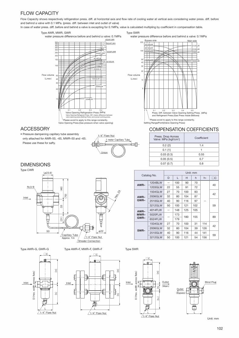
102
ACCESSORY•Pressuredampeningcapillarytubeassembly
onlyattachedforAWR–50,–65,MWR–50and–65.
Pleaseusetheseforsafty.
COMPENSATIONCOEFFICIENTS
DIMENSIONS
50Capillary TubeApprox. 1m
Shrader Connection1/4" Flare Nut
(φ23.9)
Rc3/8
(46)
(21)
33
(79)
φ22
Hex. 24
Inlet
(h)
(H)
(h1)
C
L
(Main)OutletInlet
1/4" Flare Nut
D(Hex. width across flats)
L
(Bypass)Outlet
Blind Plug
(H)
(h)
L
C
Inlet
1/4" Flare Nut
D(Hex. width across flats)
(h)
(H)
C
Inlet
L
1/4" Flare Nut
TypeCWR
1/4" Flare Nut
Union
1 meter Capillary Tube.
Unit:mm
TypeAWR–F,MWR–F,GWR–FTypeAWR–G,GWR–G TypeSWR
FLOWCAPACITYFlowCapacityshowsrespectivelyrefrigerationpress.diff.athorizontalaxisandflowrateofcoolingwateratverticalaxisconsideringwaterpress.diff.beforeandbehindavalvewith0.1MPa.(press.diff.betweeninletandoutletofvalve)Incaseofwaterpress.diff.beforeandbehindavalveisexceptingfor0.1MPa,valueiscalculatedmultiplingbycoefficientincompensationtable.
TypeAWR,MWR,GWRwaterpressuredifferencebeforeandbehindavalve:0.1MPa
TypeSWRwaterpressuredifferencebeforeandbehindavalve:0.1MPa
Flow volume
(MPa)
Bypass side Main side
Setting Range(Point)(Valve Opening Press)Please avoid to apply to this range constantly.
Press. Diff. between Valve Opening Setting Press.and Refrigerant Press.(Gas Press inside Bellows)
Flow volume
(MPa)
Valve Opening Press.(Gas pressure when valve opening)Please avoid to apply to this range constantly.
Valve Opening Refrigeration Press.Valve Opening Refrigerant Press. Diff. means difference betweenvalve opening press.(Setting Press.) and actual working press.
0.1 0.2 0.3 0.4
Press.DropAcross Valve:MPakgf/cm2 Coefficient
0.22 1.4
0.11 1
0.030.3 0.55
0.050.5 0.7
0.070.7 0.8
CatalogNo.Unit:mm
D L H h h1 C
AWR–1204BLW − 100 90 70
−
401203GLW 22 55 91 72
AWR– GWR–
1504GLW 27 70 100 8342
2006GLW 32 80 104 87
2510GLW 40 90 116 97
593212GLW 50 100 121 102
AWR– MWR– GWR–
4014FLW − 148 125 105
5020FLW−
173180 155 89
6524FLW 179
SWR–
1504GLW 27 70 100 31 11442
2006GLW 32 80 104 39 126
2510GLW 40 90 116 44 14159
3212GLW 50 100 121 54 156

103
TYPENUMBERSELECTION(SPECIFICATIONS)
TEMPERATUREACTUATEDVALVES2-WAY
TEMPERATURE ACTUATED WATER REGULATING VALVES Type OWR, HWR & XWR
GENERAL DESCRIPTION
•TypeOWR:2-waytemp.actuatedwaterregulatingvalves,open ontemperatureincrease. TypeHWR:2-waytemp.actuatedwaterregulatingvalves,open ontemperaturedecrease. TypeXWR:3-waytemp.actuatedwaterregulatingvalves.•Temperaturesensingelement(Bulb)•Bodymaterial:Bronzeforwaterandglycol, castironforwateronly
TEMPERATUREACTUATEDVALVES3-WAY
*・Pressureatwhichvalvestartsopening.・・OWR&HWRwithflangeconnectionaresuppliedwithJIS10K(0.98MPa)roundcompanionflanges(JISB22202239)andbolt/nuts.・・Capillarytube...Standardφ24mm×1meter,optional1.5,2and3meters
*・Pressureatwhichvalvestartsopening.・・Capillarytube...Standardφ24mm×1meter,optional1.5,2and3meters
Unit:°C
Unit:°C
TypeOWRTypeXWR
Temp.
Set Point
OWR HWR XWR
Main Line
Bypass Line
Temp.
Set Point
Flow Flow
Temp.
Set Point
Flow
VALVEACTIONSetPointispressureforvalveopening.Eachcheractaristicofvalvesisdifferentasfollows.
ADJUSTMENTOne full turn of adjusting screw changestemperaturesettingasshownbelow.
CatalogNo.Valve Body
Material
Connection Temp. Range
Max.Water Temp.
Max. WaterPress.
MPakgf/cm2
Max.Bulb Temp.
BulbSize (mm)
Factory Setting
Wt. (kg)Size Style
OWR–HWR–
5004G
Bronze
1/2"
Rc
30to50
60 0.9810
80
φ19×150
40
1.0
5006G 3/4" 1.2
5010G 1"
φ19×320
2.0
5012G 1–1/4" 2.2
5014F
CastIron
1–1/2"
Flange
11.5
5020F 2"φ32×350
18.3
5024F 2–1/2" 22.2
P7504G
Bronze
1/2"
Rc
50to75 100
φ19×150
60
1.0
P7506G 3/4" 1.2
P7510G 1"
φ19×320
2.0
P7512G 1–1/4" 2.2
P7514F
CastIron
1–1/2"
Flange
11.5
P7520F 2"φ32×350
18.3
P7524F 2–1/2" 22.2
CatalogNo.Valve Body
Material
Connection Temp. Range
Max.Water Temp.
Max. WaterPress.
MPakgf/cm2
Max.Bulb Temp.
BulbSize (mm)
Factory Setting
Wt. (kg)Size Style
XWR–
5004G
Bronze
1/2"
Rc
30to50
60 0.9810
80
φ19×150
40
1.0
5006G 3/4" 1.5
5010G 1"φ19×320
2.5
5012G 1–1/4" 3.0
P7504G 1/2"
50to75 100
φ19×150
60
1.1
P7506G 3/4" 1.5
P7510G 1"φ19×320
2.5
P7512G 1–1/4" 3.0
CatalogNo. ChangeinTemp.Setting
OWR– HWR– XWR–
** 04GApprox.4.0°C
** 06G
** 10G
Approx.3.0°C** 12G
OWR– HWR–
** 14F
** 20FApprox.4.0°C
** 24F
*
*
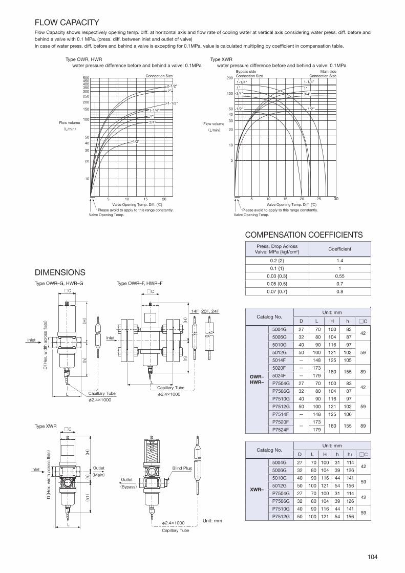
104
DIMENSIONS
Inlet
D(Hex. width across flats)
φ2.4×1000Capillary Tube
(h)
(H)
L
C
φ2.4×1000Capillary Tube
Inlet
(h)
(H)
C
14F 20F, 24F
L
Inlet
D(Hex. width across flats)
(Main)
Outlet
(h)
(h1)
(H)
L
C
Blind Plug
φ2.4×1000
Capillary Tube
(Bypass)
Outlet
TypeOWR–G,HWR–G
TypeXWR
TypeOWR–F,HWR–F
Unit:mm
COMPENSATIONCOEFFICIENTS
FLOWCAPACITYFlowCapacityshowsrespectivelyopeningtemp.diff.athorizontalaxisandflowrateofcoolingwateratverticalaxisconsideringwaterpress.diff.beforeandbehindavalvewith0.1MPa.(press.diff.betweeninletandoutletofvalve)Incaseofwaterpress.diff.beforeandbehindavalveisexceptingfor0.1MPa,valueiscalculatedmultiplingbycoefficientincompensationtable.
TypeOWR,HWRwaterpressuredifferencebeforeandbehindavalve:0.1MPa
TypeXWRwaterpressuredifferencebeforeandbehindavalve:0.1MPa
Bypass sideConnection SizeConnection Size
Main sideConnection Size
Flow volumeFlow volume
()
30
Valve Opening Temp.Please avoid to apply to this range constantly. Please avoid to apply to this range constantly.
Valve Opening Temp.
Valve Opening Temp. Diff. ()Valve Opening Temp. Diff.
1-1/4”
3/4”
1/2”
1”
1-1/4”
3/4”
1/2”
1”
1-1/4”
3/4”
1/2”
1”
1-1/2”
2-1/2”2”
Press.DropAcross Valve:MPakgf/cm2 Coefficient
0.22 1.4
0.11 1
0.030.3 0.55
0.050.5 0.7
0.070.7 0.8
CatalogNo.Unit:mm
D L H h C
OWR– HWR–
5004G 27 70 100 8342
5006G 32 80 104 87
5010G 40 90 116 97
595012G 50 100 121 102
5014F − 148 125 105
5020F − 173180 155 89
5024F − 179
P7504G 27 70 100 8342
P7506G 32 80 104 87
P7510G 40 90 116 97
59P7512G 50 100 121 102
P7514F − 148 125 106
P7520F−
173180 155 89
P7524F 179
CatalogNo.Unit:mm
D L H h h1 C
XWR–
5004G 27 70 100 31 11442
5006G 32 80 104 39 126
5010G 40 90 116 44 14159
5012G 50 100 121 54 156
P7504G 27 70 100 31 11442
P7506G 32 80 104 39 126
P7510G 40 90 116 44 14159
P7512G 50 100 121 54 156

105
PRESSURE REGULATING VALVES Type EPR
GENERAL DESCRIPTION
•Directoperated,2-wayvalvesdesignedformaintainingsuitable evaporatingpressure in refrigeration. Fittedatthe evaporator outlet to keep suitable set evaporatingpressure.
TypeEPR–B Type EPR–D
SPECIFICATIONS
TYPENUMBERSELECTION
Operation
SpecificationsDirectOperationtype
Max.WorkingPressure 2.5MPa25kgf/cm2
AirtightTestPressure 3MPa30kgf/cm2
FulidTemp. to100°C
PressureAdjustmentIncrease1604to05:0.08MPaApprox.0.82kgf/cm2/rotation
1905to07:0.05MPaApprox.0.51kgf/cm2/rotation
CatalogNo.
Equalization Portsize (mm)
NominalCapacity(U.S.R.T.)kWAdjustingRange (MPa)
kgf/cm2
Connection FactorySetting(MPa)
kgf/cm2
Wt. (kg)
CT38°C⊿P0.074MPa0.75kgf/cm2ET5°C
Type Model R22 R134a R404A R407C StyleCopper Tube (O.D.)
EPR–
1604B
Internal
15 2.69.1 1.55.3 1.96.7 2.06.9
0to0.6 0to6
Flare
1/2"
0.33
0.31605B
5/8"1905B
20 5.519 3.512 4.114 5.419 0.51906B 3/4"
1604D15 2.69.1 1.55.3 1.96.7 2.06.9
Solder
12.70.2
1605D15.88
1905D
20 5.519 3.512 4.114 5.419 0.41906D 19.05
1907D 22.23
・・Nominalcapacityisbasedoncondensingtemp.38,evaporatingtemp.5,pressuredropacrossthevalve0.074MPa0.75kgf/cm2,and SetPressureR134a...0.1MPa1kgf/cm2,R22,R407C...0.2MPa2kgf/cm2,R404A...0.3MPa3kgf/cm2
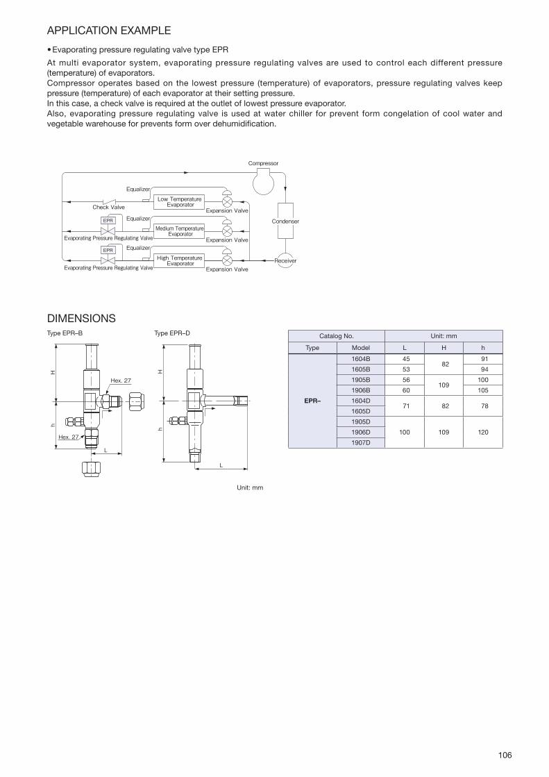
106
APPLICATION EXAMPLE
•EvaporatingpressureregulatingvalvetypeEPR
Atmulti evaporator system, evaporatingpressure regulating valves are used to control eachdifferent pressure(temperature)ofevaporators.Compressoroperatesbasedon the lowestpressure (temperature) of evaporators, pressure regulating valves keeppressure(temperature)ofeachevaporatorattheirsettingpressure.Inthiscase,acheckvalveisrequiredattheoutletoflowestpressureevaporator.Also, evaporatingpressure regulating valve is usedatwater chiller for prevent formcongelationof coolwater andvegetablewarehouseforpreventsformoverdehumidification.
Low Temperature Evaporator
Equalizer
Equalizer
Equalizer
Check Valve
Medium Temperature Evaporator
Expansion Valve
Expansion Valve
Expansion Valve
Evaporating Pressure Regulating Valve
High Temperature Evaporator
Evaporating Pressure Regulating Valve
EPR
EPR
Compressor
Receiver
Condenser
DIMENSIONS
Hh
L
Hex. 27
Hex. 27
Hh
L
TypeEPR–B Type EPR–D
Unit:mm
CatalogNo. Unit:mm
Type Model L H h
EPR–
1604B 4582
91
1605B 53 94
1905B 56109
100
1906B 60 105
1604D71 82 78
1605D
1905D
100 109 1201906D
1907D
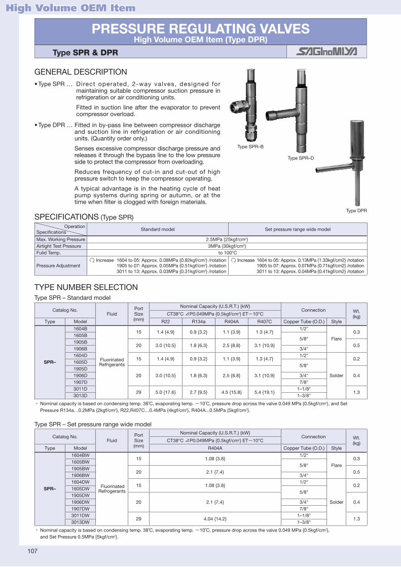
107
PRESSURE REGULATING VALVESHigh Volume OEM Item (Type DPR)
Type SPR & DPR
GENERAL DESCRIPTION•TypeSPR… Direct operated, 2-way valves, designed for
maintainingsuitablecompressorsuctionpressure inrefrigerationorairconditioningunits. Fitted insuction lineafter theevaporator topreventcompressoroverload.
•TypeDPR…Fittedinby-passlinebetweencompressordischargeand suction line in refrigerationor air conditioningunits.(Quantityorderonly.) Sensesexcessivecompressordischargepressureandreleasesitthroughthebypasslinetothelowpressuresidetoprotectthecompressorfromoverloading. Reduces frequencyof cut-in and cut-out of highpressureswitchtokeepthecompressoroperating. A typical advantage is in theheatingcycleof heatpumpsystemsduring springor autumn,or at thetimewhenfilteriscloggedwithforeignmaterials.
Type DPR
Type SPR–D
SPECIFICATIONS(TypeSPR)Operation
SpecificationsStandardmodel Setpressurerangewidemodel
Max.WorkingPressure 2.5MPa25kgf/cm2AirtightTestPressure 3MPa30kgf/cm2FulidTemp. to100°C
PressureAdjustmentIncrease1604to05:Approx.0.08MPa0.82kgf/cm2/rotation
1905to07:Approx.0.05MPa0.51kgf/cm2/rotation 3011to13:Approx.0.03MPa0.31kgf/cm2/rotation
Increase1604to05:Approx.0.13MPa1.33kgf/cm2/rotation 1905to07:Approx.0.07MPa0.71kgf/cm2/rotation 3011to13:Approx.0.04MPa0.41kgf/cm2/rotation
TYPENUMBERSELECTIONType SPR – Standardmodel
・・Nominalcapacityisbasedoncondensingtemp.38˚C,evaporatingtemp.−10˚C,pressuredropacrossthevalve0.049MPa0.5kgf/cm2,andSet・ PressureR134a…0.2MPa2kgf/cm2,R22,R407C…0.4MPa4kgf/cm2,R404A...0.5MPa5kgf/cm2.
CatalogNo.Fluid
Port Size (mm)
NominalCapacity(U.S.R.T.)kWConnection Wt.
(kg)CT38°C⊿P0.049MPa0.5kgf/cm2 ET−10°C
Type Model R22 R134a R404A R407C CopperTube(O.D.) Style
SPR–
1604B
Fluorinated Refrigerants
15 1.44.9 0.93.2 1.13.9 1.34.71/2"
Flare0.3
1605B5/8"
1905B20 3.010.5 1.86.3 2.58.8 3.110.9 0.5
1906B 3/4"1604D
15 1.44.9 0.93.2 1.13.9 1.34.71/2"
Solder
0.21605D
5/8"1905D
20 3.010.5 1.86.3 2.58.8 3.110.9 0.41906D 3/4"1907D 7/8"3011D
29 5.017.6 2.79.5 4.515.8 5.419.11–1/8"
1.33013D 1–3/8"
・・Nominalcapacityisbasedoncondensingtemp.38˚C,evaporatingtemp.−10˚C,pressuredropacrossthevalve0.049MPa0.5kgf/cm2,・ andSetPressure0.5MPa5kgf/cm2.
CatalogNo.Fluid
Port Size (mm)
NominalCapacity(U.S.R.T.)kWConnection Wt.
(kg)CT38°C⊿P0.049MPa0.5kgf/cm2 ET−10°C
Type Model R404A CopperTube(O.D.) Style
SPR–
1604BW
FluorinatedRefrogerants
15 1.083.81/2"
Flare0.3
1605BW5/8"
1905BW20 2.17.4 0.5
1906BW 3/4"1604DW
15 1.083.81/2"
Solder
0.21605DW
5/8"1905DW
20 2.17.4 0.41906DW 3/4"1907DW 7/8"3011DW
29 4.0414.21–1/8"
1.33013DW 1–3/8"
Type SPR – Setpressurerangewidemodel
High Volume OEM Item
TypeSPR–B

108
Type DPR
Thedrawingexchangeisnecessaryfortheinstructionofworkingpressuresetting.Pleasecontactusbeforeorder.
•SuctionpressureregulatingvalvetypeSPR
Suctionpressure regulating valve is installedbetweencompressor and evaporator in order to keep outletpressure(suctionpressure)underit'ssetting.In case of rapid increase of load, suction pressureregulatingvalvecouldbeusedtopreventfromoverloadofelectricmotorforcompressor.
•DischargepressureregulatingvalvetypeDPR
Dischargepressureregulatingvalveismountedinthelow-pressuresidebypasspipingfromthedischargepipingofacompressor as a control valve to control thedischargepressure tobe lower than the specifiedpressure for thepurpose of preventing the compressor frombeing anabnormalhighpressure.
APPLICATION EXAMPLE
Expansion Valve
Suction PressureRegulating Valve
Compressor
Condenser
SPR
Evaporator
Expansion ValveDischarge PressureRegulating Valve
Compressor
Condenser
Evaporator
DPR
φ23
64.2
63.2
φ7.94
φ7.94
114
φ19
Type DPR
Unit:mm
DIMENSIONS
L
Hh
Hh
L
TypeSPR–B Type SPR–D CatalogNo. Unit:mm
Type Model L H h
SPR–
1604B 4582
91
1605B 53 94
1905B 56109
100
1906B 60 105
1604D71 82 78
1605D
1905D
100 109 1201906D
1907D
3011D140 147 170
3013D
CatalogNo.Fluid PortSize
(mm)
Factory AdjustableRange
(MPa)
Connection(mm) Max.Working Press.
(MPa)kgf/cm2
Wt. (kg)Type Model Tube(I.D.) Style
DPR– 343D Fluorinated Refrigerants 3.4 0.98to2.45 7.94 Solder 2.9
29 0.11
*

109
PRESSURE REGULATING VALVES Type HPR
GENERAL DESCRIPTION
•TypeHPRcancontrol thecondensingpressurecorresponding to thechange in theoutside temperature,andprevents thecondensationpressuredecrease in thecontrol inwinter, alsosteady throughout theyearcontrolispossible.
•Thisproductproperlymaintainstheinletpressureoftheexpansionvalveandpreventsthedecreaseintherefrigerationcapacity.
•Suitableforrefrigerationsystemswithhotgasdefrosting.
SPECIFICATIONS
Max.WorkingPressure:2.9MPa29kgf/cm2(R22,R134a,R404A,R407C) 4.17MPa41.7kgf/cm2(R410A)AirtightTestPressure:3.5MPa35kgf/cm2(R22,R134a,R404A,R407C) 4.17MPa41.7kgf/cm2(R410A)FluidTemperature:・to・125
TYPENUMBERSELECTION
・・Flaretypeisproducedonly5/8and1/2.・・R410Atypeisproducedonly5/8and1/2.
CatalogNo. Portsize (mm)
ConnectionFactorySetting(MPa) Wt.(kg)
Type Model Refrigerant CopperTube(O.D.) Style
HPR–
1304D〔B〕 H(R22)M(R134a)U(R404A)P(R407C)V(R410A)
131/2"
CopperTubeO.D.[Flare]
1.32(H,U,P)0.686(M)2.15(V)
0.761305D〔B〕 5/8"
2207D 22 7/8" 1.65
CatalogNo.Portsize (mm)
Capacity(U.S.R.T.)kW
R22
Type ModelPressuredropacrossthevalve(MPa)kgf/cm2
0.0050.05
0.010.1
0.0150.15
0.020.2
0.0250.25
0.030.3
0.0350.35
0.040.4
HPR–
1304D〔B〕H13 5.97
21.08.5029.9
10.436.5
12.042.2
13.447.1
15.253.5
16.156.6
17.059.81305D〔B〕H
2207DH 22 14.751.7
20.873.1
25.690.0
29.6104
33.0116
36.1127
39.0137
41.8147
CatalogNo.Portsize (mm)
Capacity(U.S.R.T.)kW
R134a
Type ModelPressuredropacrossthevalve(MPa)kgf/cm2
0.0050.05
0.010.1
0.0150.15
0.020.2
0.0250.25
0.030.3
0.0350.35
0.040.4
HPR–
1304D〔B〕M13 5.94
20.98.4729.8
10.436.4
12.042.2
13.346.9
15.153.1
16.056.1
16.959.41305D〔B〕M
2207DM 22 14.651.5
20.772.8
25.589.5
29.3103
33.0116
35.8126
39.0137
41.8147
CatalogNo.Portsize (mm)
Capacity(U.S.R.T.)kW
R404A
Type ModelPressuredropacrossthevalve(MPa)kgf/cm2
0.0050.05
0.010.1
0.0150.15
0.020.2
0.0250.25
0.030.3
0.0350.35
0.040.4
HPR–
1304D〔B〕U13 3.90
13.75.2318.4
6.7423.7
7.8827.7
8.7330.7
9.8734.7
10.536.8
11.038.71305D〔B〕U
2207DU 22 9.5833.7
13.647.7
16.758.7
19.367.8
21.675.8
23.682.9
25.589.6
27.395.9
CAPACITYTABLE
Nominalcapacityisbasedoncondensingtemp.38,evaporatingtemp.5,andSupercoolingtemp.0.
R22
R134a
R404A

110
R410A
CatalogNo.Portsize (mm)
Capacity(U.S.R.T.)kW
R407C
Type ModelPressuredropacrossthevalve(MPa)kgf/cm2
0.0050.05
0.010.1
0.0150.15
0.020.2
0.0250.25
0.030.3
0.0350.35
0.040.4
HPR–
1304D〔B〕P13 6.14
21.68.7630.8
10.737.6
12.443.5
13.848.5
15.755.1
16.658.3
17.561.61305D〔B〕P
2207DP 22 15.153.1
21.475.1
26.392.4
30.4107
33.8119
37.0130
40.1141
42.9151
CatalogNo.Portsize (mm)
Capacity(U.S.R.T.)kW
R410A
Type ModelPressuredropacrossthevalve(MPa)kgf/cm2
0.0050.05
0.010.1
0.0150.15
0.020.2
0.0250.25
0.030.3
0.0350.35
0.040.4
HPR–1304D〔B〕V
13 6.5723.1
9.3632.9
11.440.2
13.246.4
14.751.8
16.858.9
17.762.3
18.765.81305D〔B〕V
R407C
APPLICATION EXAMPLE
Thisproduct cancontrol the condensingpressure corresponding tothechangeintheoutsidetemperature,andpreventsthecondensingpressuredecreaseinthecontrolinthewinter,alsosteadythroughouttheyearcontrolispossible.Thisproductproperlymaintains the inlet pressureof the expansionvalveandpreventsthedecreaseintherefrigerationcapacity.Suitableforuseinrefrigerationsystemswithhotgasdefrostingandinextremelycoldregion.
DIMENSIONS
CondensingPressurehigherthanthesetvalue(summer)C→RCondensingPressurelowerthanthesetvalue(winter)B→R
Unit:mm
※φ68(φ92)※R410A:φ71
80(120)
96(135)
92(95)
117(160)
71(70)
80(120)
S
B
C
R
Condensation pressureregulating valve(Type HPR) Air-cooled type condenser
Expansion Valve
CompressorEvaporator
Accumulator
SolenoidValves
TypeHPR–1304to1305D(TypeHPR–2207D)

111
DIAPHRAGM TYPE STOP VALVES Type ADV
GENERAL DESCRIPTION
•Thevalvecanbeusedonthelinesofdeliverygas,liquid,suctiongasandhotgas,etc.
•The va lve is appl icable to not only F luor inatedrefrigerants,butalsoair.
•In spiteof its compactnessand lightweight, theportdiameter iscomparatively largetoenableto flowa largeamount.
•The large diameter handlemakes easy and smoothrotationeveninvacuumcondition.
•Carefullyprocessedvalvewithselectedmaterialprovideslongtroublefreeserviceanddependableoperation.
•TypeADVcannotbeusedinareverseflow.
φD
L
h
(H)
φD
φd
L
Eh
(H)
TypeADV–D
TypeADV–DY
TypeADV–BY
TypeADV–B
DIMENSIONS
Unit:mm
TYPENUMBERSELECTION(SPECIFICATIONS) Unit:MPakgf/cm2
CatalogNo. PortSize (mm) CvValue
Connection Max.WorkingPressure
FluidTemp. (°C)
Wt. (kg)CopperTube(O.D.) Style
ADV–
902BY9
0.35 1/4"
Flare
3.636 −40to120
0.26
903BY 0.79 3/8" 0.32
1404BY 14 1.61 1/2" 0.51
1605BY16
2.82 5/8" 0.85
1606BY 3.46 3/4" 1.13
902DY9
0.35 1/4"(6.35)
Solder
0.24
903DY 0.79 3/8"(9.53) 0.28
1404DY 14 1.61 1/2"(12.7) 0.46
1605DY
16
2.82 5/8"(15.88) 0.76
1606DY3.46
3/4"(19.05)0.91
1607DY 7/8"(22.23)
CatalogNo.Unit:mm
L H h φD φd E
ADV–
902BY 80 75 20
52
− −903BY 85 75.5
19.51404BY 101 87.5
1605BY 128 98 2370
1606BY 135 102 25
902DY165
75 20
52
6.58
903DY 75.519.5
9.65
1404DY 190 87.5 12.95 10
1605DY
200
98 23
70
16.15 12
1606DY102 25
19.314
1607DY 22.45

112
BELLOWS TYPE STOP VALVES Type NBV
GENERAL DESCRIPTION
•Thevalveisabellowssealtypestopvalve.•Thereisnoexternalleakagefromthegroundpart.•It canbeused for fluorocarbon refrigerant circuits suchasR22,R134a,R404A,compressedairetc.
•FluidTemperature:− 30to120
TYPENUMBERSELECTIONFlareType
PipeThreadType
CatalogNo.PortSize (mm) CvValue
ConnectionWt. (kg)Type Model Pressureclass(Max.Working
Pressure)(Mpa) Size Style
NBV-
502B
X(2.94)
5 0.36 1/4"
Flare(JISB8607)
0.3
803B 7.5 0.82 3/8" 0.4
1004B 10 1.4 1/2" 0.6
1305B 13 2.4 5/8" 0.8
1606B 16 4.2 3/4" 1.2
502AMB 5 0.39 1/4" InletROutletFlare(JISB8067)
0.3
803AMB 7.5 0.89 3/8" 0.4
NBV-
502B
Y(3.53)
5 0.36 1/4"
Flare(JISB8607)
0.3
803B 7.5 0.82 3/8" 0.4
1004B 10 1.4 1/2" 0.6
1305B 13 2.4 5/8" 0.8
1606B 16 4.2 3/4" 1.2
502AMB 5 0.39 1/4" InletROutletFlare(JISB8067)
0.3
803AMB 7.5 0.89 3/8" 0.4
CatalogNo.PortSize (mm) CvValue
ConnectionWt. (kg)Type Model Pressureclass(Max.Working
Pressure)(Mpa) Size Style
NBV-
802G
X(2.94)
7.5 0.8 1/4"
Rc
0.3
1003G 10 1.4 3/8" 0.4
1304G 13 2.9 1/2" 0.6
2006G 20 6.7 3/4" 1.1
802AG 7.5 0.8 1/4" 0.3
1003AG 10 1.5 3/8" 0.4
1304AG 13 3.1 1/2" 0.6
2006AG 20 7.3 3/4" 1.1
NBV-
802G
Y(3.53)
7.5 0.8 1/4"
Rc
0.3
1003G 10 1.4 3/8" 0.4
1304G 13 2.9 1/2" 0.6
2006G 20 6.7 3/4" 1.1
802AG 7.5 0.8 1/4" 0.3
1003AG 10 1.5 3/8" 0.4
1304AG 13 3.1 1/2" 0.6
2006AG 20 7.3 3/4" 1.1

113
H
L
h
L
hH
L
H
L
Hh
CatalogNo. L H h
NBV–
502B 60 61 12
803B 70 65 15
1004B 90 78 17
1305B 100 85 18
1606B 110 88.5 26
502AMB 35 55 30
803AMB 40 65 40
802G 54 65
−1003G 60 78
1304G 65 79
2006G 80 105
802AG 24 58 24
1003AG 28 71 28
1304AG 33 73 33
2006AG 40 105 40
TypeNBV–B
TypeNBV–G
TypeNBV–AMB
TypeNBV–AG
DIMENSIONS
Unit:mm

FLOW SENSORS・ ・・・・・・・・・・・・・・・・・・・・・・・・・・・ 115
Type ELK
FLOW SWITCHES・ ・・・・・・・・・・・・・・・・・・・・・・・・・・ 116
Type FQS
DRAIN PUMPS・・・・・・・・・・・・・・・・・・・・・・・・・・・・・・ 117
Type SDP
DRAIN PUMPS・・・・・・・・・・・・・・・・・・・・・・・・・・・・・・ 118
Type MDP
CONDENSER FAN SPEED CONTROLLERS・・・・・119–120
Type RGE
CONDENSER FAN SPEED CONTROLLERS・・・・・・・・ 121
Type XGE
TEMPERATURE RECORDERS・・・・・・・・・・・・・・・・・・ 122
Type AKM & BKM
CONTROL APPLIANCES FOR HOT WATER SUPPLY UNITS・・・・123–124
Type CRV, VSV, WSV, HEV, XJV, QJV, TCV, CAV, ELK
CO2 REFRIGERANT APPLICATIONS・ ・・・・・・・・・125–127
Type CCB, HSK, HPV, UKV–J & JKV
BELLOWS・ ・・・・・・・・・・・・・・・・・・・・・・・・・・・・・・・・ 128
Type HBL & WSL
OTHER CONTROLS & VALVES・・・・・・・・・・・・・・・・・・ 129
Type RKV & BI-METAL (No. 03, 05 & 24)
OT
HE
R C
ON
TR
OL
EQ
UIP
ME
NT
OTHER CONTROL EQUIPMENT

115
FLOW SENSORSHigh Volume OEM Item
Type ELK
GENERAL DESCRIPTION
•Turbinetypeflowsensorhavinganimpellertorotateinproportiontoflowrate.
•ForburnerOn-Off of hotwater supply system, accu-mulationofautomatichotwatersupply.
•Pulseoutputcorrespondingflowrate.•Max.workingpressure:1MPa•Fluidtemperature:0to80°C(Nofrozen)•Ratedvoltage:4.5to13.2V.DC•Housingbodymaterial:PPS•Installationisverticalriserpipingorhorizontalpiping.
SPECIFICATIONS
FLOWRATE–OUTPUTPULSECHARACTERISTICS
DIMENSIONS
00
10
50
100
Horizontal piping
Vertical riser piping
Output Pulse
(pps)
1.5 5 10Flow rate(L/min)
15
No.3 Black: GND
Terminal Cable Color
No.2 Yellow: Vout
No.1 Red: Vcc150
50
30゜30゜
φ20 φ30
Inlet
φ30
φ25
φ25
φ19
+0.06
-0.1
+0.06
-0.1
Unit:mm
High Volume OEM Item
CatalogNo. RangeofFlowRate (L/min)
FlowRate–OutputPulseCharacteristics
OutputMode Max.OutputCurrent (mA)
Wt. (kg)BasedFlowRate
(L/min)Verticalriserpiping
(pps)Horizontalpiping
(pps)
ELK–0508 1.5to25
1.5 9.6±2 7.7±2
OpenCollector 15 0.02510 68.7±6 69.2±6
15 102.9±12 104.1±12

116
FLOW SWITCHES Type FQS
GENERAL DESCRIPTION
•Foruseonliquidlinessuchaswater,ethyleneglycol,oranynon-corrosive fluid in chillers, pumps, condensers,boilers,etc.
•WithS.P.D.T.contactmechanism.•Paddleconsistsofthreesegmentsthatcanberemovedortrimmedforusein1to6"pipe.
•Dripproofmodels:Availableuponrequest.
OPERATIONADJUSTMENTRANGETABLE
•Whentheoperatingvalueisnotspecified,theflowswitchisshippedwith theoperating value set around theminimumflowrate.
•Whenyou turn the flowadjustingscrew clockwise, theoperatingpointgoesup.Whenyouturnitcounterclockwise,theoperatingpointgoesdown.
•Whenmorethantwopaddlesisattached,youcanchangethe flow rate adjustment rangeby removing thepaddlesonebyoneinorderofthelongerpaddlefirst.
SPECIFICATIONS
・・Enclosure:IP20(IP62model:availableuponrequest.)
*2・Flowdecrease...Flowamountatwhichtheswitchoperatesonflowdecrease. Flowincrease...Flowamountatwhichtheswitchoperatesonflowincrease.
DIMENSIONS50
28
64
(189)
8959
1.5
12±1.2
35
98.5
29
Flow
Earth Mark
R1"
Hex.36
1" Paddle
2" Paddle
3" Paddle
Unit:mm
markapplicable(availableuponrequest)
ULlisted(availableuponrequest)
CatalogNo. Paddle Size
Connection Max.Working Pressure
MPakgf/cm2
FluidTemp.(°C)
Max.FlowVelocity(m/s)
Wt. (kg)Size Style
FQS–U30G 1"+2"+3" 1" R 0.9810 5to80 2 0.6
ELECTRICAL RATINGSRatedVoltage(V)
RatedCurrent(A)
PowerFactor (cosφ)
125V.AC
250V.AC
Non-InductiveCurrent 1 15 15
InductiveCurrent
FullLoad 0.75 3.5 2.5
LockedRotor 0.45 21 15
PipeSize
Paddle Size
Adjustmentrange(L/min)
Min. Max.
FlowDecrease FlowIncrease FlowDecrease FlowIncrease
1"
1"
18 28 45 55
1–1/4" 43 53 100 120
1–1/2" 63 78 135 162
2"1"+2" 50 65 150 180
1" 151 181 220 264
2–1/2"1"+2" 105 126 355 426
1" 356 427 360 432
3"
1"+2"+3" 100 120 225 270
1"+2" 226 271 480 576
1" 481 577 510 612
4"
1"+2"+3" 200 240 385 462
1"+2" 386 463 820 984
1" 821 985 870 1044
5"
1"+2"+3" 350 420 594 713
1"+2" 595 714 1265 1518
1" 1266 1519 1342 1610
6"
1"+2"+3" 530 636 836 1003
1"+2" 837 1004 1780 2136
1" 1781 2137 1890 2268
*2
*1
*1・ConnectionscrewedlengthtoaTeejointis12±1.2mm.
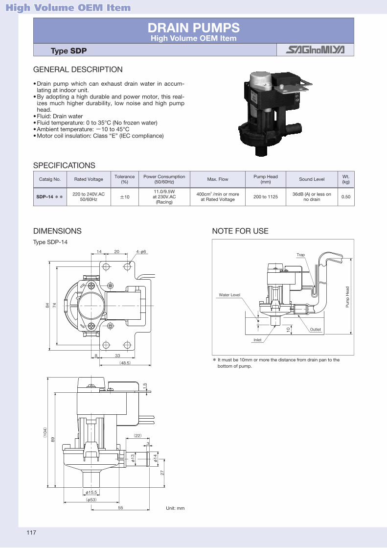
117
DRAIN PUMPSHigh Volume OEM Item
Type SDP
DIMENSIONS NOTEFORUSE
14 20
(22)
3
8 33
(48.5)
4‒φ6
8489(104)
74
1.5
φ13
27
φ14
(φ53)
φ15.5
55
Water Level
Inlet
Outlet10
Pump Head
Trap
* Itmustbe10mmormorethedistancefromdrainpantothebottomofpump.
TypeSDP-14
Unit:mm
GENERAL DESCRIPTION
•Drainpumpwhichcanexhaustdrainwater in accum-latingatindoorunit.
•Byadoptingahighdurableandpowermotor,thisreal-izesmuchhigherdurability, lownoise andhighpumphead.
•Fluid:Drainwater•Fluidtemperature:0to35°C(Nofrozenwater)•Ambienttemperature:−10to45°C•Motorcoilinsulation:Class“E”(IECcompliance)
High Volume OEM Item
SPECIFICATIONS
CatalgNo. RatedVoltage Tolerance(%)
PowerConsumption(50/60Hz) Max.Flow PumpHead
(mm) SoundLevel Wt. (kg)
SDP–14 ** 220to240V.AC50/60Hz ±10
11.0/9.5Wat230V.AC(Racing)
400cm3/minormoreatRatedVoltage 200to1125 36dB(A)orlesson
nodrain 0.50

118
DIMENSIONS NOTEFORUSE
8
InletOutlet
Pump HeadWater Level
Trap
* Itmustbe8mmormorethedistancefromdrainpantothebottomofpump.
TypeMDP-12
SPECIFICATIONS
DRAIN PUMPSHigh Volume OEM Item
Type MDP
GENERAL DESCRIPTION
•Drainpumpwhichcanexhaustdrainwater inaccumlatingatindoorunit.
•Byadoptingahighdurableandpowermotor, this realizesmuchhigherdurability,lownoiseandhighpumphead.
•Fluid:Drainwater•Fluidtemperature:0to35°C(Nofrozenwater)•Ambienttemperature:−10to45°C•Motorcoilinsulation:Class“E”(IECcompliance)
High Volume OEM Item
CatalgNo. RatedVoltage Tolerance(%) PowerConsumption Max.Flow PumpHead
(mm) SoundLevel Wt. (kg)
MDP-12 ** 12V.DC ±100.9W
(Racing)400cm3/minormoreatRatedVoltage 150to1125 40dB(A)orless
onnoDrain 0.22
95
φ16
3
φ17φ15
27
(23)
φ15.5
(φ48)
55
φ73.2 20
115°
115°
130゜
Unit:mm

119
CONDENSER FAN SPEED CONTROLLERS Type RGE
GENERAL DESCRIPTION
•Themost suitable for controlling the condenser fanspeedof freezingor refrigeration condensingunits,packageair conditioners, or other unitswhich areoperatedthroughouttheyear.
•Keepcondensingpressure constant inwinter andintermediateseasonsforstableoperation.
•Followingmodes are selectableduring low-speedoperation. MinimumSpeedOperation ・・CutoffOperation
•Excellentelectricalnoise-resistantdesign.•Applicabletotheexternalforcedoperationswitch.
TYPENUMBERSELECTION
*・1:Thepressureatwhichthecontroldelivers95%outputeffectivevoltage(VRMS).*・2:Pressurewidthwhereeffectivevoltagecorrespondstotheminimumspeedorcausescutoffoperation・・Min.speed:Fanmotorwillbekeptrunningatthespecificvalue(V%)whenpressurebandincreasemorethanE.P.B.・・Cutoff:Fanmotorwillbestoppedwhenpressuredecreasetothespecificvalue(V%)forR.M.S.・・Forotherpressuresetvaluesormin.speed/cutoffsetvalues,pleasecontactus.
markapplicable
listed(availableuponrequest)
Single-phasetype
Three-phasetype
OPERATION
Theoperatingcharacteristicsmayvaryaccordingtothevoltage,frequency,andfanmotorcharacteristics.
①・Single-phasetype ②・Three-phasetype
50Hz at 230V
45
z at 230V
H06
E.P.B.(Fixed)
.S.M.R egatloV evitceffE
)%V
(
10095
35
Pressure
Min. Speed
Max. SpeedF.V.S.(Adjustable)
ffO tu
C
E.P.B.(Fixed)
.S.M.R egatloV evitceffE
)%V
(
10095
35
Pressure
Min. Speed
Max. SpeedF.V.S.(Adjustable)
ffO tu
C
SPECIFICATIONS
•Max.workingpressure:4.7MPa•Controlmethod:Phasecontrol•Enclosure:IP54
CatalogNo.
F.V.S.Setting(MPa)E.P.B. (MPa) Refrigerants Electrical
Ratings FunctionAmbient Temp. (°C)
Operation Wt. (kg)Factory
Set
AdjustingRange
Min. Max. Ampere
RGE–Z1L4–7 1.9 0.8 2.8 Fixed0.6 R22,R404A,R407C
Singlephase200to240V.AC50/60Hz
0.2to3A Atapprox.45%(50Hz)atapprox.35%(60Hz)CutOfforMinimumSpeedfunctionisselectablewithchangeoverswitch.
Defaultsetting: CutOff
−20to55 ①
0.36RGE–Z1L6–7 3.2 1.6 3.9 Fixed0.9 R410A
RGE–Z1N4–7 1.9 0.8 2.8 Fixed0.4 R22,R404A,R407C0.2to4A 0.5
RGE–Z1N6–7 3.2 1.6 3.9 Fixed0.8 R410A
RGE–Z1P4–7 1.9 0.8 2.8 Fixed0.4 R22,R404A,R407C0.2to6A 0.54
RGE–Z1P6–7 3.2 1.6 3.9 Fixed0.8 R410A
RGE–Z1Q4–7 1.9 0.8 2.8 Fixed0.4 R22,R404A,R407C0.2to8A 0.58
RGE–Z1Q6–7 3.2 1.6 3.9 Fixed0.8 R410A
RGE–Z3R4–7 1.6 0.8 2.8 Fixed0.4 R22,R404A,R407CThreephase 200to240V.AC 50/60Hz
0.2to5A Atapproximately35%,CutOfforMinimumSpeedfunctionisselectablewithchangeoverswitch.Defaultsetting: Min.Speed
−20to50
②
1.4RGE–Z3R6–7 3.2 1.6 3.9 Fixed0.8 R410A
RGE–Z3T4–7 1.6 0.8 2.8 Fixed0.6 R22,R404A,R407C0.2to7A 1.53
RGE–Z3T6–7 3.2 1.6 3.9 Fixed0.8 R410A
RGE–X3R4–7 1.6 0.8 2.8 Fixed0.4 R22,R404A,R407C Threephase 380to415V.AC50/60Hz
0.2to5A −15to50 1.4RGE–X3R6–7 3.2 1.6 3.9 Fixed0.8 R410A
*1 *2

120
WIRING
Ground
Switch
Fan Motor
Circuit Breaker or Fuse
Ground
Switch
Fan MotorCircuit Breaker or Fuse
Off: Auto speedOn: Full speed
Forced Operation SwitchExternal
Forced Operation SwitchExternal
for 2A (RGE-Z1) for 4A, 6A, 8A (RGE-Z1)
Fan Motor
Off: Auto speedOn: Max. speed
Power Supply
Switch
GroundCircuit Breaker or FuseOperationSwitch
ForcedExternal
Useexternalforcedoperationswitchthatisabletoreducecurrentconsumptionoffanmotors. Useaforcedoperationswitchwithnon-voltagecontactsignal.
DIMENSIONS
10595
001
051
900±100
1/4" Female Flare with Schrader Copper Packing
12
95104
75(125)
900±100
1/4" Female Flare with Schrader Copper Packing
4-φ4.4 4-φ5.4
67
for 8A
5252
(36)φ22.5 Conduit Gland
67
for 6A
(36)φ22.5 Conduit Gland
85
for 4A
7
(36) φ22.5 Conduit Gland
for 3A
(102)
(55)
φ22.5 Conduit Gland
185175160
002
031
900±100
1/4" Female Flare with Schrader Copper Packing
4-φ5.4
89
58
61
for 5A(REG-Z3,X3)
(67)
φ22.5 Conduit Gland
89
58
61
for 7A(REG-Z3)
(67)
φ22.5 Conduit Gland
Single-phasetype Three-phasetype
Single-phasetype Three-phasetype
Unit:mm

121
CONDENSER FAN SPEED CONTROLLERS Type XGE
SPECIFICATIONS
•Controlmethod:Phasecontrol•Max.workingpressure:4.7MPa•Powersupply:[RatedVoltage]200to240V.AC singlephase[Frequency]50/60Hz[RatedAmp.]0.2to3A•Pressureconnection:1/4”・FemaleflarewithSchrader(7/16-20UNF)•Enclosure:IP65
TYPENUMBERSELECTION
OPERATION
Min. speed
Pressure Pressure
E.P.B.(Fixed)
E.P.B.(Fixed)C
ut off
Max. speed Max. speed
F.V.S. (Adjustable) F.V.S. (Adjustable)
Effective voltage(V%)
Effective voltage(V%)
50Hz 230V
60Hz 230V 50
Hz 230V
60Hz 230V
100(95)
50(45)
(35)
100(95)
50(45)
(35)
DIMENSIONS
M
189.2
8.8
964.2
(48.4)
12.5
63.2
(15.9)
(8)
Schrader
Pressure admission port
Rangeadjusting screw
Heat sink
Copper packing
PIN 1.6±0.1
1.5±0.1
10.5
(7)
φ1.5 •Plug•Gasket•Plugfixingscrew•Plasticbag
*Theoperatingcharacteristicmay varyaccordingtothevoltage,frequency,andfanmotorcharacteristics.
WIRINGS
M
2
1
Connector
Fan motor
Circuit breaker or Fuse
Switch
Supplied with a gasket. Cable exit in 4 directions possible.
Power supply
ACCESSORIES(XGE-1Plugpartsset)
Unit:mm
XGE–4CC–7andXGE–6CC–7(Cutofftype) XGE–4MC–7andXGE–6MC–7(Min.speedtype)
GENERAL DESCRIPTION
•Themostsuitableforcontrollingthespeedofacondenserfanof freezing and refrigeration condensing unit, package airconditioner andother unitswhichareoperated throughout ayear.
•Keepcondensingpressureconstant inwinterand intermediateseasonsforstableoperation.
markapplicable listed(availableuponrequest)
Cutoff:Fanmotorwillbestoppedwhenpressuredecreasetothe specificvalue(V%)forR.M.S.Min.speed:Fanmotorwillbekeptrunningatthespecificvalue(V%) whenpressurebandincreasemorethanE.P.B.
*1F.V.S.:FULLVOLTAGESETPOINTThepressureatwhichthecontroldelivers95%outputeffectivevoltage.*2E.P.B.:EFFECTIVEPROPORTIONALBANDPressurewidthwhereeffectivevoltagecorrespondstothemin.speedorcausescutoffoperation.
CatalogNo.
F.V.S.Setting(MPa)E.P.B(MPa) Refrigerants Function Ambienttemp.
(°C)Fluidtemp.
(°C)Wt. (kg)FactorySet
AdjustingRange
Min. Max.
XGE–4CC–71.9 1.0 2.5 0.6 R22,R407C,R404A
Cutofftype
−20to55 −20to70 0.19XGE–4MC–7 Min.speedtype
XGE–6CC–72.8 2.2 3.9 0.7 R410A
Cutofftype
XGE–6MC–7 Min.speedtype
*2*1

TEMPERATURE RECORDERS Type AKM & BKM
GENERAL DESCRIPTION
•Portabletemperaturerecorderwidelyapplicableforuseinrefrigeration,airconditioningandmedicalfields.
•High recording accuracywith quartz drivingmotor.Recordingpaperfeedingspeed:3.3mmperhour
•Motordrivenbydrycellbattery:1.5V.DC,C–type Life1year
•TypeBKM is a temperature sensitive recordingpaperwhichissuppliedasstandardforuse12monthperiod.SpecifycatalogNo.whenorderadditionalpapers.
•Higher and lower alarmpointers canbe setwithin therange.
WIRINGS
Higher Alarm Pointer
Lower Alarm Pointer
Alarm PowerSource
Capillary Tube
Sensing Bulb
HigherAlarmTerminal
LowerAlarmTerminal
•Standardcapillarytubelength:φ2.0×2000mm (Plasticcoveringoncapillarytubeavailable.)
•Alarmlamporbuzzercanbeconnectedtothecontactson higherandloweralarmterminals.
DIMENSIONS
162149140.4
Less than 15
φ12.7 (φ15.9) ( ): Type 0620
100(170)
183.7
06111
Capillary Tube φ2×2000
Unit:mm
TYPENUMBERSELECTION(SPECIFICATIONS)
・・AlarmContact:Eachoneonupperandlowerlimitpointer,100V.AC1A,200V.AC0.5A.
Unit:°C
CatalogNo. ApplicationExamples
Temp.Range Indicating Accuracy
Recording Accuracy
AlarmAccuracy AlarmPowerSource
CatalogNo,ofRecording Paper
Wt. (kg)Min. Max.
AKM–4014LH1X ForRefrigeration &Freezing −40 14
±2±0.5
plusIndicating Accuracy Temp.Scale
±2
100to120V.ACBKM–4044X
1.6
AKM–4014LH2X 200to240V.AC
AKM–0054LH1X
For Air-conditioning
0 54100to120V.AC
BKM–0054XAKM–0054LH2X 200to240V.AC
AKM–1044LH1X−10 44
100to120V.ACBKM–4044X
AKM–1044LH2X 200to240V.AC
AKM–0620LH1XForMedicalUse −6 20
−6to2・・±22to8・・±0.8
8to20・・±2
100to120V.ACBKM–0620X
AKM–0620LH2X 200to240V.AC
122

123
CONTROL APPLIANCES FOR HOT WATER SUPPLY UNITS Type CRV, VSV, WSV, HEV, XJV, QJV, TCV, CAV, ELK
PressureReducingValve TypeCRV
•Thisvalvecontrolswaterpressurefortheunit.
•HiVolumeOEMItem
ReliefValve TypeWSVandVSV
•Thisvalvebeingprovidedwithadiaphragmishighlyreliableandthemostsuitableforthemaintenanceofahotwatersupplyunit.(WSVtype)
•This valve is providedwith a negative pressureoperatingdevice. If thehotwater supply unit orpipingbecomesanegativepressure internally, thisdevice introduces the atmospheric pressure toprevent thedamageof theunit anda reverse flow.(VSVtype)
•HiVolumeOEMItem(Resinbodytype)
TypeCRV
TypeWSV TypeVSV
SolenoidValve TypeHEV
•This small solenoid valve is used for feedwater,coolingwaterandhotwatercircuitsofthehotwatersupplyunit.
•Abronze casting type areprepared as thebodymaterial.
TypeHEV
ElectricComplexValve TypeXJV
•This three-waymixedproportional valve applies tothecoldandhotwaterofafullyautomatichotwatersupplyunit.
•It controls themixing ratioof coldwater andhotwater to produce an opt imum mixed watertemperature.
•HiVolumeOEMItem
TypeXJV
GENERAL DESCRIPTION
•Controlappliancesforhotwatersupplyunit

124
CheckValve TypeTCV
•Thisisaresintypecheckvalveforwater.
•HiVolumeOEMItem
TypeTCV
AutomaticAirVentValve TypeCAV
•Thisvalveautomaticallyreleasestheairgeneratedinthehotwatercircuitoutside.
•Sincetheunitandjointeachbeingmadeofstainlesssteelmaterial (SUS) are assembled together, it hasexcellent corrosion resistance, andalso, it is safeandsanitary.
•This valve is characterizedwith a large exhaustvolumeandanexcellentairexhaustperformance.
TypeCAV
ElectricProportionalValve TypeQJV
•This two-wayproportional valveapplies to thecoldandhotwaterofa fullyautomatichotwatersupplyunit.
•It controls the flowof coldwater, hotwater, andwaterforindustrialforuse.
•HiVolumeOEMItemTypeQJV
FlowSensor TypeELK
•This turbinesystemflowsensor isprovidedwithanimpellerwhichrotatesinproportiontotheflow.
•This sensor is used for starting and stopping theburnerofaninstantaneoushotwatersupplyunitandalsointegratingtheautomatichotwaterfeeding.
•Itoutputspulsesaccordingtotheflow.
•HiVolumeOEMItem
TypeELK

High Volume OEM Item
125
CO2 REFRIGERANT APPLICATIONSHigh Volume OEM Item
Type CCB, HSK, HPV, UKV–J & JKV
GENERAL DESCRIPTION
•UsedforCO2refrigerantapplications.•Availableforextremehighpressure.•Application:Bottlecooler,displaycase, heatpumpwaterheaters, vendingmachine
Type CCB TypeHSK TypeHPV TypeUKV–J
WIRING
Type HSK PowerSupply
Connector
Receiver
1
2
3
5V. DC±0.25V.
-+ 321
(φ7.5)
(φ6)
(55)
(10.5)
(92.3)
11.8
φ26
(19.7)
Contact pin No.
DIMENSIONSTypeHSK
Unit:MPakgf/cm2
PRESSURECONTROLforHighPressure[TypeCCB]
SPECIFICATIONS
・・Allowablefluidtemperature:−30to100°C
CatalogNo.Setting
Max.Pressure ContactFunction PressureConnection
TerminalConstruction Application Wt.
(kg)on off
CCB–**** 10100 15150 15150 SPST(HighCut) 1/4"Solder Open HighPressureCutOut 0.07
PRESSURESENSORforHighPressure[TypeHSK]
SPECIFICATIONS
・・Allowablefluidtemperature:−30to120°C・・Ambienttemperature:−30to100°C
Unit:MPakgf/cm2
CatalogNo. PressureRange
SupplyVoltage Output Accuracy Current
ConsumptionLoad
ResistanceAirtightPressure
PressureConnection
Wt.(kg)
HSK–BC150D–*** 0to1500to15 5V.DC±0.25V 0.5to4.5V.DC ±2.5%F.S. Max.10mA Min.10kΩ 15150 φ6Solder 0.07
ELECTRICAL RATINGSCategoryofRatings TRating MRating
RatedVoltage(V)
RatedCurrent(A)
PowerFactor(cosφ)
24V.DC 12V.DC 120V.AC 240V.AC
Non-InductiveCurrent 1 0.01to0.05 1to6
InductiveCurrent
FullLoad 0.75− − − −
InrushCurrent −
CONTACTFUNCTION
PRESS. RISING
14
10.58
57.726.2
φ28
φ6.35
Faston#250
DIMENSIONSType CCB
Unit:mm
Unit:mm

126
SOLENOIDVALVEforHighPressure[TypeHPV]
TYPENUMBERSELECTION(SPECIFICATIONS)
・・O.P.D.:OperatingPressureDifferential(byairpressure)・・Ambienttemperature:−20to50°C・・Allowablefluidtemperature:−30to120°C
DIMENSIONSTypeHPV–102DQ1HPV–122D TypeHPV–402DQ3
Unit:mm
Unit:MPakgf/cm2
CatalogNo. PortSize(mm) CvValue
Connection O.P.D. Max.WorkingPressure Operation Wt.
(kg)CopperTubeO.D. Style Min. Max.
HPV–102DQ1 1.0 0.0281/4"
Solder
010.0100
13.0130
Normalclose
0.05
HPV–122D 1.2 0.038 13.8138 0.09
HPV–402DQ3 4.0 0.32 1/4" 0 14.0140 0.09
HPV–825DS 7.8 0.54 5/16" 0.11 15.0150 0.13
ELECTRICALRATINGOFSOLENOIDCOILS
*IECcompliance
ValveType RatedVoltage Tolerance(%)
Voltampere PowerConsumption
(W)InsulationClass
Wt.(kg)Running Inrush
HPV–102DQ1 100V.AC200V.AC
50/60Hz ±10
11/8 32/27 6/4.5
ClassBMolded
0.13
HPV–122D 16/13 52/38 9/8 0.16
HPV–402DQ3200V.AC
10/8 32/26 5.5/4.5 0.16
HPV–825DS 14/11 42/33 7/6 0.20
*
O.D. 6.35
39
47
45
(88){(107)}
O.D. 6.35
43.8
21.4
(123.5)
65
64.5
O.D.6.35
O.D.6.35
(110)
46
48.5
φ48
O.D. 7.94
O.D. 7.94
TypeHPV–825DS
Pleasecontactusifotherconnectionarerequired.

127
ELECTRONICEXPANSIONVALVEforHighPressure[TypeUKV–J,・JKV]
TYPENUMBERSELECTION(SPECIFICATIONS)
*・1:CT=・−5°C,ET=・−25°C,SH=・0°C,SC=0°C*・2:Gascoolerinlettemp.=・70°C,Gascooleroutlettemp.=・22°C,ET=・6°C,SH=・0°C・・Allowablefluidtemperature:−30to70°C・・Ambienttemperature:−30to70°C
DIMENSIONSTypeUKV–J
TypeJKV–20D TypeJKV–24D
Unit:mm
50
(100)
47φ6.35
(47)
(43)
(32)
φ6.35
(37)
φ48 φ48
54
(119)
φ7.94 φ7.94
56
54(119)
56
A sideConn.
B sideConn.
A sideConn.
B sideConn.
A sideConn.
B sideConn.
φ7.94
φ7.94
Unit:MPakgf/cm2
CatalogNo. 0PULSEFLOW
PortSize(φmm)
CvValue
Capacity(U.S.R.T)kWMax.Working
Pressure
OperatingPressureDifferential
Connection(Solder)(mm) Wt.
(kg)R744(CO2) R744(CO2)Bside Aside
UKV–J14DOPEN TYPE
1.4 0.056 2.910.3 3.913.6
151500to10
0to100
φ6.35OD φ6.35OD 0.05CLOSE TYPE
JKV–20DOPEN TYPE
2.0 0.12 6.221.9 8.229.0
φ7.94OD φ7.94OD 0.2CLOSE TYPE
JKV–24DOPEN TYPE
2.4 0.17 8.730.7 11.640.7CLOSE TYPE 0to80to80
SPECIFICATIONSOFCOIL
*IECcompliance
ValveType Excitationmethod RatedVoltage&Current InsulationClass Wt.(kg)
UKV–J14D
1-2Phaseexcitation12V.DC.・・・・260mA/Phase ClassE
Molded
0.13
JKV–20D 0.14
JKV–24D 12V.DC.・・・・380mA/Phase 0.19
*
*1 *2
50
(100)
47φ6.35
(47)
(43)
(32)
φ6.35
(37)
φ48 φ48
54
(119)
φ7.94 φ7.94
56
54
(119)
56
A sideConn.
B sideConn.
A sideConn.
B sideConn.
A sideConn.
B sideConn.
φ7.94
φ7.94
50
(100)
47φ6.35
(47)
(43)
(32)
φ6.35
(37)
φ48 φ48
54
(119)
φ7.94 φ7.94
56
54
(119)
56
A sideConn.
B sideConn.
A sideConn.
B sideConn.
A sideConn.
B sideConn.
φ7.94
φ7.94

128
BELLOWSHigh Volume OEM Item
Type HBL & WSL
Hydraulicallycorrugatedbellowsmadefromatinwallmetalpipe.Materialandspecificationsareselectableforapplications.Matchformassproductionandqualityareverystable.
Materialexample:Phosphorbronze,berylliumcopper,stainlesssteel, inconel,etc.
•ApplicationsAerospace,marine, chemical, refrigeration, air conditioning, electric,construction,medical,andothervariouskindsofindustrys.Bellowsassembledwithfittingsarealsoavailable.
Hydraulically-FormedBellowsTypeHBLetc...
Bellowsmadefromprecision-madetinwallmetalrings.Suitableforextremelyprecisionuse.Materialisselectableforapplications.
Materialexample:Stainlesssteel,inconel,etc.
WeldingBellowsTypeWSLetc...
WeldingbellowsforlowpressureandlongstrokeuseMainCharacteristics:UsinganticorrosionmaterialSUS316L
Longstrokestructure WithEndFittingsforeasytoinstall Lowpriceandfastdelivery
WeldingBellowsforvacuumuse〈Sbellows〉
High Volume OEM Item

129
OTHER CONTROLS & VALVES Type RKV & BI-METAL(No.03, 05 & 24)
GENERAL DESCRIPTION
VariouscontrolsandvalvesareavailablebySaginomiya.Thefollowingaresomeexamples.
3-WAYCHANGE-OVERVALVE TypeRKV
•Controlapplianceforchangingoverflowdirectionintwoevaporatortypehouseholdretrigerator.
BI-METALDISCTHERMOSTATS Type03,05,24
•Forvariousapplications,wideavailabletemperaturerange:− 20to260°C
•Autoresetormanualreset
Pleasecontactthecompanyfordetailinformationontheabovecontrols.
TypeRKV

英文総合カタログ_T 表2/表3 1c
2018.12改訂 T版_Gai
背幅:7.2mm(本文132p)
FOSHAN HUALU AUTOMATICCONTROLS LIMITED (China)No.59&61, Wenhua Nan Road, Chancheng DistrictFoshan, Guangdong, ChinaSales & ManufacturingTel: +86 757 8383 1558 Fax: +86 757 8383 1218
RIMSA SAGINOMIYA, S.A. DE C.V. (Mexico)Av. Central No. 126, Parque IndustrialToluca 2000, Km. 52.8 Carretera TolucaNaucalpan, C. P. 50200, Toluca, Edo. deMexico, MexicoSalesTel: +52 722 279 3680 Fax: +52 722 279 0234
Danfoss Saginomiya Sp. z o.o. (Poland)ul. Chrzanowska 5, 05-825 GrodziskMazowiecki, PolandManufacturingTel: +48 22 7550 500 Fax: +48 22 7550 505
SAGINOMIYA EUROPE Sp. z o.o. (Poland)Aleje Jerozolimskie 212 02-486 Warsaw, PolandSalesTel: +48 22 101 30 00 Fax: +48 22 101 30 01
SAGINOMIYA AMERICA, INC. (USA)655 Metro Place South suite 700, Dublin Ohio 43017, U.S.A. SalesTel: +1 614 766 7390 Fax: +1 614 766 7391
Saginomiya (Thailand) Co., Ltd. (Thailand)159 Serm-mit Tower 19th Fl., Room No.1903/1Sukhumvit 21 Rd., Klongtoey-NuaWattana, Bangkok 10110, ThailandSales & ManufacturingTel: +662 260 8364 Fax: +662 260 8366
Shinjyuku Garden Tower 22F8-2, Okubo 3-chome, Sinjyuku-kuTokyo, 169-0072 JapanTel : +81 3 6205 9123 Fax : +81 3 6205 9125E-mail: [email protected]
OVERSEAS NETWORK
First edition 1975. 4 Z
WARNINGFailure to read and follow all instruction carefully before installing or operation the product could cause personal injury and/or property damage.
Specifications are subject to change without notice.
CONSENT RELATED TO DISCLAIMERS
Revsion1(2014.12) 2014.10
We, SAGINOMIYA SEISAKUSHO, INC., (hereinafter referred to as “Saginomiya”), truly appreciate your choosing Saginomiya’s products (hereinafter referred to as “Products”).When the Products are used, this document as provided below shall be applicable except to the extent that there is anything to the contrary in any applicable estimate, agreement, catalogue, specification, etc.
CONFIRMATION OF OPERATIONAll customers using the Products (hereinafter referred to as “Customers”) are requested to, after properly installing the Products, test the operation of the Products to confirm that all the systems in connection with the Products fully function.In order to prevent the occurrence of bodily injury, fire accidents, serious damage, etc., in connection with the Customers’ machinery or equipment due to improper installation of the Products, Saginomiya kindly requests the Customers to take the necessary safety measures by preparing safe designs such as a fail-safe design (*1) and a fire spread prevention design, as well as to make the proper adjustments for product reliability necessary for fault-tolerance (*2).
(*1) Fail-safe design: Design to ensure safety in the event of any mechanical failure(*2) Fault-tolerance: Utilization of redundancy technology
Periodic Inspection of the ProductsBe sure to confirm the proper operation of the Products and keep records of such operation at least once a year.
Saginomiya shall be held harmless and be indemnified by the Customers from any damages incurred due to the Customers failing to conduct the above operational procedures, provided, however, that, this shall not apply if the damages which the Customers incurred due to the defect of the Products caused by Saginomiya.
RESTRICTIONS OF USEThe Products are designed and manufactured for the purpose of using them for cooling and heating and refrigerating appliances and air conditioning equipment or various industrial equipment, but are not designed and manufactured for the purpose of using the Products for any instrument or system related to human life or health purposes.Therefore, the use of the Products in fields related to items (1) through (3) below is not intended whatsoever. Saginomiya shall be held harmless and be indemnified from any and all damages incurred by use of the Products under item (3).
(1) In any field related to nuclear power and radiation;(2) In any field related to space or seafloor equipment;(3) In any equipment or device requiring a high degree of reliance on such equipment or device with respect to which it is reasonably foreseeable that failure or malfunction of the equipment or device would either directly or indirectly cause serious damage to human life, health or property;
Also, when using the Products under the fields related to items (1) through (9) below (except for item (3), in relation to which the Products must never be used), please be sure to notify our Saginomiya’s contact desk in charge of sales and obtain Saginomiya’s prior written approval for such use. Saginomiya shall be held harmless and be indemnified from any and all damages incurred by use of the Products in relation to these fields if the Customers do not notify Saginomiya’s contact desk and obtain Saginomiya’s prior written approval.
(4) Transportation device (railroad, aviation, ship or vessel, vehicle equipment, etc.);(5) Disaster-prevention or crime-prevention device;(6) Facility or application directly related to medical equipment, burning appliances, electro thermal equipment, amusement rides and devices, facilities/applications associated directly with billing, or device using flammable fluid;
(7) Equipment requiring high reliance on supply systems such as electricity, gas, water, etc., in large-scale communication system, or in transportation or air traffic control system;
(8) Facilities that are to comply with regulations of governmental / public agencies or specific industries or(9) Other machineries or equipment equivalent to those set forth in the above items (4) to (8) which require for high reliability and safety.
It is recommended to replace the Products within 5 to 10 years of delivery if no other duration of use is provided in the applicable specifications or instruction manual because the conditions and environment of use also have an impact on the Products.
SCOPE OF WARRANTYSAGINOMIYA WILL PROVIDE THE CUSTOMERS WITH REPLACEMENT OR REPAIRED THE PRODUCTS DELIVERED, FREE OF COST, ONLY WITHIN ONE YEAR OF DELIVERY TO THE CUSTOMER, IF FAILURE OCCURS IN THE CUSTOMERS’ EQUIPMENT USING THE PRODUCTS DUE TO A DEFECT OF THE PRODUCTS; PROVIDED, HOWEVER, THAT IN ANY EVENT THE RATIO OF THE AMOUNT THAT SAGINOMIYA BEARS FOR THE DAMAGES INCURRED BY THE FAILURE OF THE PRODUCTS OR CUSTOMERS’ EQUIPMENT SHALL NOT EXCEED THE PRICE OF THE PRODUCTS WE DELIVERED. IN ADDITION, SAGINOMIYA SHALL BE HELD HARMLESS AND BE INDEMNIFIED FROM ANY AND ALL DAMAGES INCURRED WHEN THE FAILURE OF THE CUSTOMERS’ EQUIPMENT OCCURRED DUE TO ANY CAUSE SET FORTH BELOW.
(1) WHEN CAUSED BY INAPPROPRIATE HANDLING OR USE OF THE PRODUCTS BY THE CUSTOMERS (SUCH AS NOT COMPLYING WITH THE CONDITIONS, ENVIRONMENTAL SPECIFICATIONS OR CAUTIONS INDICATED IN ANY APPLICABLE CATALOGUE, SPECIFICATIONS, INSTRUCTION MANUAL, ETC.);
(2) WHEN FAILURE OCCURRED DUE TO ANY REASON OTHER THAN THE PRODUCTS;(3) WHEN CAUSED BY MODIFICATION OR REPAIR OF THE PRODUCTS MADE BY ANYONE OTHER THAN SAGINOMIYA OR DESIGNEE OF SAGINOMIYA;
(4) WHEN CAUSED BY THE USE OF THE PRODUCTS IN VIOLATION OF THE ABOVE “RESTRICTIONS OF USE” OR “CONFIRMATION OF OPERATION”;
(5) WHEN SUCH FAILURE WAS NOT REASONABLY FORESEEABLE AT THE TIME OF SAGINOMIYA’S SHIPMENT; OR(6) BY ANY OTHER CAUSE NOT ATTRIBUTABLE TO SAGINOMIYA, SUCH AS AN ACT OF GOD, DISASTER, OR ACT OF ANY THIRD PARTY.
PLEASE NOTE THAT THE CUSTOMERS WILL NOT BE ENTITLED TO ANY OF THE ABOVE WARRANTY IF THE CUSTOMERS PURCHASED THE PRODUCTS FROM INTERNET AUCTION, ETC.
SAGINOMIYA AMERICA, INC. (USA)655 Metro Place South suite 700, Dublin Ohio 43017, U.S.A. SalesTel: +1 614 766 7390 Fax: +1 614 766 7391
Headquarters Tokorozawa Plant Yonezawa Production Department
Sayama Plant

T
AUTOM
ATIC CON
TROLS
Printed in Japan2018.12 z
Shinjuku Garden Tower 22F8-2, Okubo 3-chome, Shinjuku-ku, Tokyo, 169-0072 JapanTel : +81 3 6205 9123 Fax : +81 3 6205 9125E-mail : [email protected] : http://www.saginomiya-global.com/en/
AutomaticControls
REFERENCE INFORMATIONAPPROVAL STANDARD LIST
PRESSURE CONTROLSTEMPERATURE & HUMIDITY CONTROLS
PRESSURE & TEMPERATURE CONTROLS INFORMATIONEXPANSION VALVES
SOLENOID VALVES & CONTROL VALVESOTHER VALVES
OTHER CONTROL EQUIPMENT
背幅:7.2mm(本文132p)
英文総合カタログ_T 表1/表4 4c
2018.12改訂 T版_Gai