automated manufacture of a shape-adaptive large hydrofoil
TRANSCRIPT

Automated Manufacture of a Shape-Adaptive Large Hydrofoil
SOTELO ZORRILLA Marco Salvador
Master Thesis
presented in partial fulfillment of the requirements for the double degree:
“Advanced Master in Naval Architecture” conferred by University of Liege "Master of Sciences in Applied Mechanics, specialization in Hydrodynamics,
Energetics and Propulsion” conferred by Ecole Centrale de Nantes
developed at University of Rostock, Germany in the framework of the
“EMSHIP” Erasmus Mundus Master Course
in “Integrated Advanced Ship Design”
Ref. 159652-1-2009-1-BE-ERA MUNDUS-EMMC
Supervisor: Dr.-Ing Robert Bronsart, University of Rostock
Internship tutor: Prof. Gangadhara Prusty, University of New South Wales
Reviewer: Jean-Baptiste Souppez, Southampton Solent University
Rostock, February 2019

ii Automated manufacture of shape-adaptive large hydrofoil
Master Thesis developed at University of New South Wales, Australia; and at University of Rostock, Germany
This page is intentionally left blank.

iii Marco Salvador Sotelo Zorrilla
“EMSHIP” Erasmus Mundus Master Course, period of study September 2017 – February 2019
DECLARATION OF AUTHORSHIP
I declare that this thesis and the work presented in it are my own and has been generated by me
as the result of my own original research.
Where I have consulted the published work of others, this is always clearly attributed.
Where I have quoted from the work of others, the source is always given. Except for such
quotations, this thesis is entirely my own work.
I have acknowledged all main sources of help.
Where the thesis is based on work done by myself jointly with others, I have made clear exactly
what was done by others and what I have contributed myself.
This thesis contains no material that has been submitted previously, in whole or in part, for the
award of any other academic degree or diploma.
I cede copyright of the thesis in favour of the University of Rostock
Date:
Marco Salvador Sotelo Zorrilla

iv Automated manufacture of shape-adaptive large hydrofoil
Master Thesis developed at University of New South Wales, Australia; and at University of Rostock, Germany
This page is intentionally left blank.
v Marco Salvador Sotelo Zorrilla
“EMSHIP” Erasmus Mundus Master Course, period of study September 2017 – February 2019
ABSTRACT
Automated manufacture of a shape-adaptive large hydrofoil
By SOTELO ZORRILLA Marco Salvador
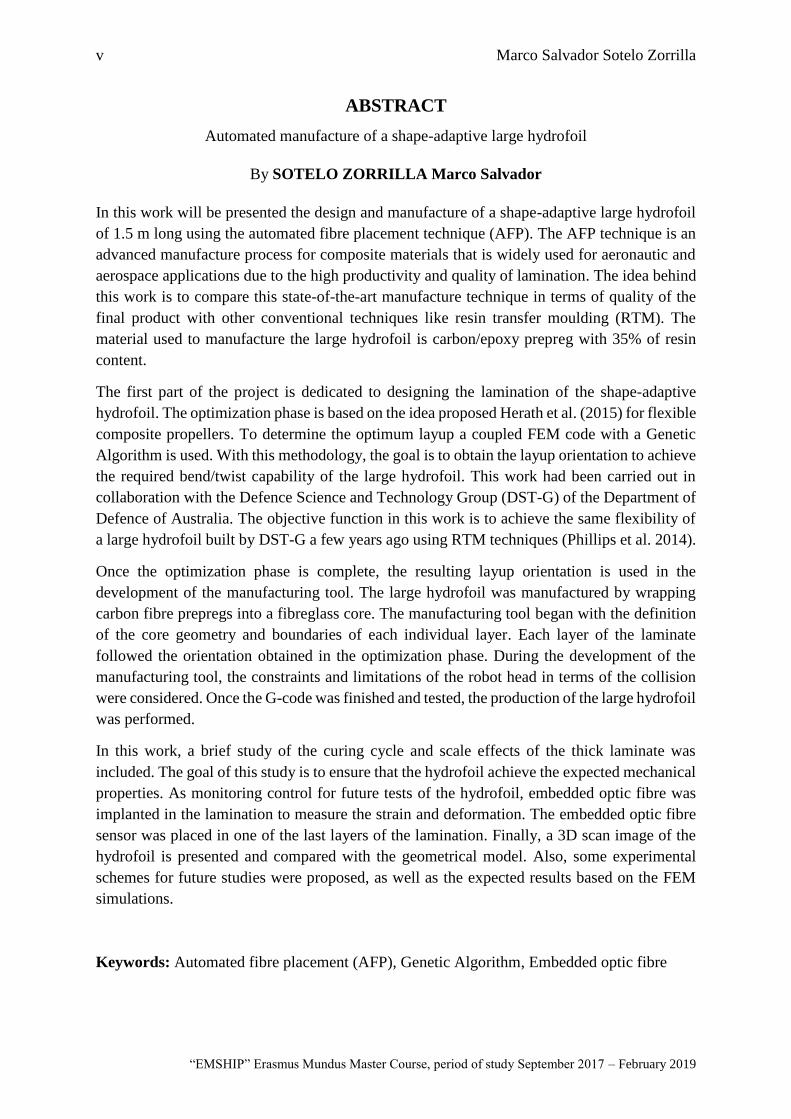
In this work will be presented the design and manufacture of a shape-adaptive large hydrofoil
of 1.5 m long using the automated fibre placement technique (AFP). The AFP technique is an
advanced manufacture process for composite materials that is widely used for aeronautic and
aerospace applications due to the high productivity and quality of lamination. The idea behind
this work is to compare this state-of-the-art manufacture technique in terms of quality of the
final product with other conventional techniques like resin transfer moulding (RTM). The
material used to manufacture the large hydrofoil is carbon/epoxy prepreg with 35% of resin
content.
The first part of the project is dedicated to designing the lamination of the shape-adaptive
hydrofoil. The optimization phase is based on the idea proposed Herath et al. (2015) for flexible
composite propellers. To determine the optimum layup a coupled FEM code with a Genetic
Algorithm is used. With this methodology, the goal is to obtain the layup orientation to achieve
the required bend/twist capability of the large hydrofoil. This work had been carried out in
collaboration with the Defence Science and Technology Group (DST-G) of the Department of
Defence of Australia. The objective function in this work is to achieve the same flexibility of
a large hydrofoil built by DST-G a few years ago using RTM techniques (Phillips et al. 2014).
Once the optimization phase is complete, the resulting layup orientation is used in the
development of the manufacturing tool. The large hydrofoil was manufactured by wrapping
carbon fibre prepregs into a fibreglass core. The manufacturing tool began with the definition
of the core geometry and boundaries of each individual layer. Each layer of the laminate
followed the orientation obtained in the optimization phase. During the development of the
manufacturing tool, the constraints and limitations of the robot head in terms of the collision
were considered. Once the G-code was finished and tested, the production of the large hydrofoil
was performed.
In this work, a brief study of the curing cycle and scale effects of the thick laminate was
included. The goal of this study is to ensure that the hydrofoil achieve the expected mechanical
properties. As monitoring control for future tests of the hydrofoil, embedded optic fibre was
implanted in the lamination to measure the strain and deformation. The embedded optic fibre
sensor was placed in one of the last layers of the lamination. Finally, a 3D scan image of the
hydrofoil is presented and compared with the geometrical model. Also, some experimental
schemes for future studies were proposed, as well as the expected results based on the FEM
simulations.
Keywords: Automated fibre placement (AFP), Genetic Algorithm, Embedded optic fibre

vi Automated manufacture of shape-adaptive large hydrofoil
Master Thesis developed at University of New South Wales, Australia; and at University of Rostock, Germany
This page is intentionally left blank.
vii Marco Salvador Sotelo Zorrilla
“EMSHIP” Erasmus Mundus Master Course, period of study September 2017 – February 2019
CONTENTS DECLARATION OF AUTHORSHIP ....................................................................................... 3
ABSTRACT ............................................................................................................................... 5
List of Figures ............................................................................................................................ 9
Introduction ................................................................................................................................ 1
CHAPTER 1 .............................................................................................................................. 3
Literature review ........................................................................................................................ 3
1.1. Optimization techniques for composite propellers and hydrofoils ............................. 3
1.2. Automated manufacture in composites ....................................................................... 6
1.3. Thick laminate manufacture ........................................................................................ 8
1.4. Sensors for control of composite structures .............................................................. 10
1.5. Methodology ............................................................................................................. 15
CHAPER 2 ............................................................................................................................... 17
Design and optimization of the large hydrofoil ....................................................................... 17
2.1. Introduction ............................................................................................................... 17
2.2. Optimization process ................................................................................................. 19
Objective function and design variables ............................................................ 20
2.3. Definition of the FEM model using Shell elements .................................................. 21
Geometrical model and mesh............................................................................. 22
Boundary conditions .......................................................................................... 25
Optimization results ........................................................................................... 26
2.4. Solution of the FEM using solid elements ................................................................ 29
CHAPTER 3 ............................................................................................................................ 31
Development of the manufacture tool and construction of the hydrofoil ................................ 31
3.1. Introduction to automatic fibre placement techniques .............................................. 31
Main advantages and potential limitations of AFP ............................................ 34
3.2. Developing of the Manufacturing tool ...................................................................... 35
viii Automated manufacture of shape-adaptive large hydrofoil
Master Thesis developed at University of New South Wales, Australia; and at University of Rostock, Germany
Definition of the geometrical model .................................................................. 36
Ply stack and layup definition ............................................................................ 38
Generation of the G-code ................................................................................... 39
3.3. Manufacture of the large hydrofoil ........................................................................... 42
Layup of the large hydrofoil .............................................................................. 43
Complications and challenges during the manufacture ..................................... 47
CHAPTER 4 ............................................................................................................................ 53
Thick laminate curing .............................................................................................................. 53
4.1. Introduction to autoclave curing for advanced composites ....................................... 53
4.2. Thick laminate curing test ......................................................................................... 56
4.3. Curing of the large hydrofoil ..................................................................................... 58
CHAPTER 5 ............................................................................................................................ 61
Proposed embedded sensor monitoring ................................................................................... 61
5.1. Introduction to fibre optic sensing ............................................................................ 61
5.2. Arrangement of the distributed fibre sensing ............................................................ 63
5.3. Placement of the distributed fibre sensing ................................................................ 64
CHAPTER 6 ............................................................................................................................ 67
Results and potential tests ........................................................................................................ 67
6.1. Introduction ............................................................................................................... 67
6.2. 3D Scan of the cured hydrofoil ................................................................................. 67
6.3. Expected results from quasistatic tests ...................................................................... 71
CONCLUSIONS...................................................................................................................... 73
FURTHER WORK .................................................................................................................. 75
ACKNOWLEDGEMENTS ..................................................................................................... 77
Bibliography ............................................................................................................................ 79

ix Marco Salvador Sotelo Zorrilla
“EMSHIP” Erasmus Mundus Master Course, period of study September 2017 – February 2019
List of Figures
Figure 1 Automated Fibre Placing (AFP) machine at the Advanced Manufacture laboratory,
UNSW, Australia (Source: http://advanced-composites.co/facilities_unsw/) ........................... 2
Figure 2 Results from optimized hydrofoil, source Mulcahy et al. (2011) ................................ 4
Figure 3 Triangular mesh (upper) and NURBS mesh (lower) model of a B-series propeller
blade, source Herath et al. (2015) .............................................................................................. 5
Figure 4 Cavitation tunnel result of CL and CD of the hydrofoil, source Herath (2016) .......... 6
Figure 5 Manufacture process of a carbon/epoxy foil using AFP technique, source [6]........... 7
Figure 6 Standard curing cycle (top) and Optimized curing cycle (bottom), source Gower et al.
(2016) ......................................................................................................................................... 9
Figure 7 Sensor placing in the hydrofoil, source Davis et al. (2012) ...................................... 11
Figure 8 Embedded fibre in a CFRP hydrofoil, source Maung et al. (2015) ........................... 12
Figure 9 Strain measurements and FEM results, source Maung et al. (2015) ......................... 13
Figure 10 Large hydrofoil used for fatigue tests, source Phillips et al. (2014)........................ 17
Figure 11 Proposed geometry of the large hydrofoil ............................................................... 18
Figure 12 Genetic Algorithm flow chart, source Onwubolu (2003) ........................................ 19
Figure 13 Experimental results of large hydrofoil, source Phillips et al. (2014) ..................... 21
Figure 14 Material properties of the carbon/epoxy prepreg .................................................... 22
Figure 15 Geometry model of the hydrofoil using shell elements........................................... 23
Figure 16 Mesh model using shell elements ............................................................................ 24
Figure 17 Test arrangement of the large hydrofoil, source Phillips et al. (2014) .................... 25
Figure 18 Boundary conditions of the FEM model ................................................................. 25
Figure 19 Convergence for the Trailing edge .......................................................................... 26
Figure 20 Convergence for the Leading edge .......................................................................... 27
Figure 21 Deformation of the solid model ............................................................................... 30
x Automated manufacture of shape-adaptive large hydrofoil
Master Thesis developed at University of New South Wales, Australia; and at University of Rostock, Germany
Figure 22 Manufacture using AFP of a section of the fuselage of an Airbus A350, source
Coriolis Composites (2015) ..................................................................................................... 32
Figure 23 Automated fibre placement (AFP) main components, source Automated Dynamics
(2010) ....................................................................................................................................... 32
Figure 24 Diagram of AFP technique, source Coriolis Composites (2015) ............................ 33
Figure 25 Geometry of the Fibreglass core.............................................................................. 36
Figure 26 Definition of the mandrel ........................................................................................ 37
Figure 27 Graphical representation of a full wrapping boundary ............................................ 40
Figure 28 Graphical representation of boundaries and trajectories ......................................... 41
Figure 29 Beginning of the manufacturing process ................................................................. 43
Figure 30 Finish of the first stack of 4 plies at 90 Degrees (Full wrapping) ........................... 44
Figure 31 Placement of the Layer 5, first boundary ................................................................ 44
Figure 32 Layer 7, -75 Degrees, Mandrel 1 ............................................................................. 45
Figure 33 Layer 32, -75 Degrees, Mandrel 2 ........................................................................... 45
Figure 34 Layer 54, -30 Degrees, Mandrel 3 ........................................................................... 45
Figure 35 Layer 80, -45 Degrees (Complete surface), Mandrel 4 ........................................... 46
Figure 36 Final layer (96), Full wrapping at 90 Degrees, Mandrel 4 ...................................... 46
Figure 37 Discontinuity in the generated bands at -15 degrees ............................................... 48
Figure 38 Shrinkage in layer 1, around the trailing edge. ........................................................ 49
Figure 39 Shrinkage of the tows due to the small radius curvature ......................................... 49
Figure 40 Gaps and overlap of the tows during the placement................................................ 50
Figure 41 Manual placement of prepreg patch ........................................................................ 51
Figure 42 Autoclave scheme, source Campbell (2003) ........................................................... 54
Figure 43 Typical carbon/epoxy curing cycle, source Campbell (2003) ................................. 55
xi Marco Salvador Sotelo Zorrilla
“EMSHIP” Erasmus Mundus Master Course, period of study September 2017 – February 2019
Figure 44 Sample of thick laminate with thermocouples. (Property of Automated Composites
Laboratory, UNSW Engineering) ............................................................................................ 56
Figure 45 Curing of thick laminate using the proposed curing cycle. (Property of Automated
Composites Laboratory, UNSW Engineering) ........................................................................ 57
Figure 46 Experimental results from thick laminate curing cycle test. (Property of Automated
Composites Laboratory, UNSW Engineering, elaborated by Phyo Maung) ........................... 57
Figure 47 Cured large hydrofoil .............................................................................................. 59
Figure 48 Scattered spectrum in a solid material, source Guemes (2010) ............................... 62
Figure 49 Proposed distribution of the Embedded distributed optic fibre sensor.................... 63
Figure 50 Placement of the distribute optic fibre sensor ......................................................... 65
Figure 51 Distributed optic fibre sensor in the laminate.......................................................... 65
Figure 52 3D Scan of the large hydrofoil, Parametric view (top), Top face (middle) and Bottom
face (bottom). (Property of Automated Composites Laboratory, UNSW Engineering) ......... 68
Figure 53 Cut section between final hydrofoil and expected geometry. (Property of Automated
Composites Laboratory, UNSW Engineering, elaborated by Phyo Maung) ........................... 69
Figure 54 Comparison between final hydrofoil and expected geometry. Top face (top), and
bottom face (bottom) (Property of Automated Composites Laboratory, UNSW Engineering,
elaborated by Phyo Maung) ..................................................................................................... 70
Figure 55 Expected strain measurements along the principal axis during quasi-static tests ... 71

xii Automated manufacture of shape-adaptive large hydrofoil
Master Thesis developed at University of New South Wales, Australia; and at University of Rostock, Germany
This page is intentionally left blank
1 Marco Salvador Sotelo Zorrilla
Introduction
In the past decades the usage of composite as material construction for marine applications had
increased exponentially. Special devices like rudders, hydrofoils and propeller blades have
been investigated worldwide and proved to be more efficient if some flexibility can be achieved
(Young et al. (2016), Wu et al. (2015), Zarruk et al. (2014) and Ducoin et al. (2012),). The
most common material used in this task is carbon reinforcement plastic (CRP). One remarkable
advantage of using CRP as construction material is the high corrosion resistance in marine
environment. But the main reason why CRP propeller blades and hydrofoils are gaining
popularity is due to the bend/twist capability that allows them to adapt the pitch when working
under different loading conditions. This pitch adaptive capability can increase the efficiency of
the propeller and hydrofoils when it works in out of the design conditions as mentioned in
Herath et al. (2013). The bend/twist capability under hydrodynamic loads is normally called
hydroelastic tailoring. This is a passive capability does not need additional mechanism to work
as in the case of controllable pitch propellers, decreasing significantly the acquisition cost.
With the potential use of composite materials to create high efficiency structures in different
fields of engineering, many automated techniques have been developed in the last decades.
One of the most used is the Automated Fibre Placement (AFP). Specially used in aerospace
applications due to the high-quality control during the manufacture and capability to elaborate
large scale parts. AFP is and advance manufacture technique for composite materials which
could work with thermoset and thermoplastic materials. This technique consists in a robot head
that place tows or tapes in a prefabricate mould in a desire orientation, covering the required
surface. The robot head has a heating torch that pre-cure the tape for the case of thermoset
materials. Since the procedure fully automated, it is possible to manufacture complex
geometries and work with precise orientations of the fibres without difficulties.
One of the main advantages of this manufacture process is the low level of voids and
imperfections inside the lamination compared to the traditional manufacture techniques as
Resin Transfer Moulding (RTM), Vacuum Assisted Resin Infusion (VARI) or manual layup.
Besides the precision and high quality of the manufacture, by using AFP techniques is possible
to integrate features that are unconceivable to perform manually, like curved fibres to increase
the bend/twist capability of a laminate. Due to the potential use of AFP techniques in many
other engineering fields the demand of studies is increasing significantly.
2 Automated manufacture of shape-adaptive large hydrofoil
Master Thesis developed at University of New South Wales, Australia; and at University of Rostock, Germany
Due to the high cost, full scale tests in composite structure are not very common for research
purpose according to Jackson (1990). The main advantage of performing full scale test,
especially with thick laminates, is to measure the real mechanical properties of the composite.
Since as the thickness increase, the strength of the laminate tends to decrease, to predict the
real behaviour of a composite structure, large scale tests are required. Therefore, in this work,
a full-scale large hydrofoil will be manufacture using AFP techniques, to measure the real
behaviour of a thick laminates and determine potential challenges of using this state-of-the-art
manufacture technique.
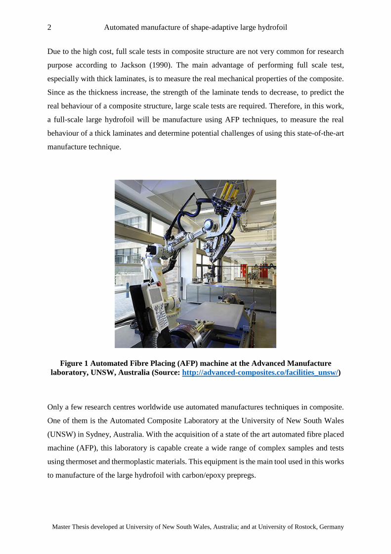
Figure 1 Automated Fibre Placing (AFP) machine at the Advanced Manufacture
laboratory, UNSW, Australia (Source: http://advanced-composites.co/facilities_unsw/)
Only a few research centres worldwide use automated manufactures techniques in composite.
One of them is the Automated Composite Laboratory at the University of New South Wales
(UNSW) in Sydney, Australia. With the acquisition of a state of the art automated fibre placed
machine (AFP), this laboratory is capable create a wide range of complex samples and tests
using thermoset and thermoplastic materials. This equipment is the main tool used in this works
to manufacture of the large hydrofoil with carbon/epoxy prepregs.
3 Marco Salvador Sotelo Zorrilla
“EMSHIP” Erasmus Mundus Master Course, period of study September 2017 – February 2019
CHAPTER 1
Literature review
1.1. Optimization techniques for composite propellers and hydrofoils
It has been widely studied the benefit of flexible hydrofoils and therefore the potential
improvement by using shape adaptive marine propellers. Concerning the design and
optimization of shape adaptive composite propeller blades and hydrofoils there are several
works developed in the last decade. Most of the design optimization tools have either solely
consider hydrodynamic effects with low fidelity methods or used high fidelity methods with
low number of design variables, according to Young et al. (2016).
Many authors have been developing optimization tools to model shape-adaptive propeller
blades and hydrofoils using composite material but not many experimental validations are
available. The main objective of these methods is to optimize the layout of the propeller to have
an adaptive shape that could be more efficient in one or two off design conditions. Having
several objective functions increases the computational cost and generally no more than 2 off
design conditions in most of the optimization techniques, according to Young et al. (2016).
One of the first works regarding the layup optimisation of composite propellers was presented
by Li and Lee (2004). For the hydrodynamical model they used numerical lifting-surface
theory. By using this procedure, the blade is represented by a discrete number of vortex and
sources located in the camber of the surface of the blade. Hence, the complex geometry of the
propeller can be accommodated. For the optimization phase, they used Genetic Algorithm to
find the proper ply orientation at certain design condition. Once this ply orientation was found,
a second run of the method should be run again to determine unloaded shape.
The method presented by Mulcahy et al. (2010) uses hydroelastic tailoring to adapt the
propeller’s blade shape in changing flows, resulting in an improvement of the efficiency when
compared to the rigid based propeller. The proposed method used a rigid propeller shape as a
reference base, then it is slightly modified to another desired shape that will have higher
efficiency at different loading conditions compared to the rigid base shape. The hydrodynamic
load at the off-design conditions are calculated using a commercial CFD code. Then by running
4 Automated manufacture of shape-adaptive large hydrofoil
Master Thesis developed at University of New South Wales, Australia; and at University of Rostock, Germany
a general optimization method they found the ply orientation and the unloaded shape that will
achieve the desire deformation at the different loading conditions.
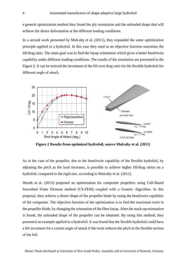
In a second work presented by Mulcahy et al. (2011), they expanded the same optimization
principle applied to a hydrofoil. In this case they used as an objective function maximize the
lift/drag ratio. The main goal was to find the layup orientation which gives a better bend/twist
capability under different loading conditions. The results of the simulation are presented in the
Figure 2. It can be noticed the increment of the lift over drag ratio for the flexible hydrofoil for
different angle of attack.
As in the case of the propeller, due to the bend/twist capability of the flexible hydrofoil, by
adjusting the pitch as the load increases, is possible to achieve higher lift/drag ration on a
hydrofoil, compared to the rigid one, according to Mulcahy et al. (2011).
Herath et al. (2013) proposed an optimization for composite propellers using Cell-Based
Smoothed Finite Element method (CS-FEM) coupled with a Genetic Algorithm. In this
proposal, they achieve a desire shape of the propeller blade by using the bend/twist capability
of the composite. The objective function of the optimization is to find the maximum twist in
the propeller blade, by changing the orientation of the fibre layup. After the stack-up orientation
is found, the unloaded shape of the propeller can be obtained. By using this method, they
presented an example applied to a hydrofoil. It was found that the flexible hydrofoil could have
a lift increment for a certain angle of attack if the twist reduces the pitch in the flexible section
of the foil.
Figure 2 Results from optimized hydrofoil, source Mulcahy et al. (2011)
5 Marco Salvador Sotelo Zorrilla
“EMSHIP” Erasmus Mundus Master Course, period of study September 2017 – February 2019
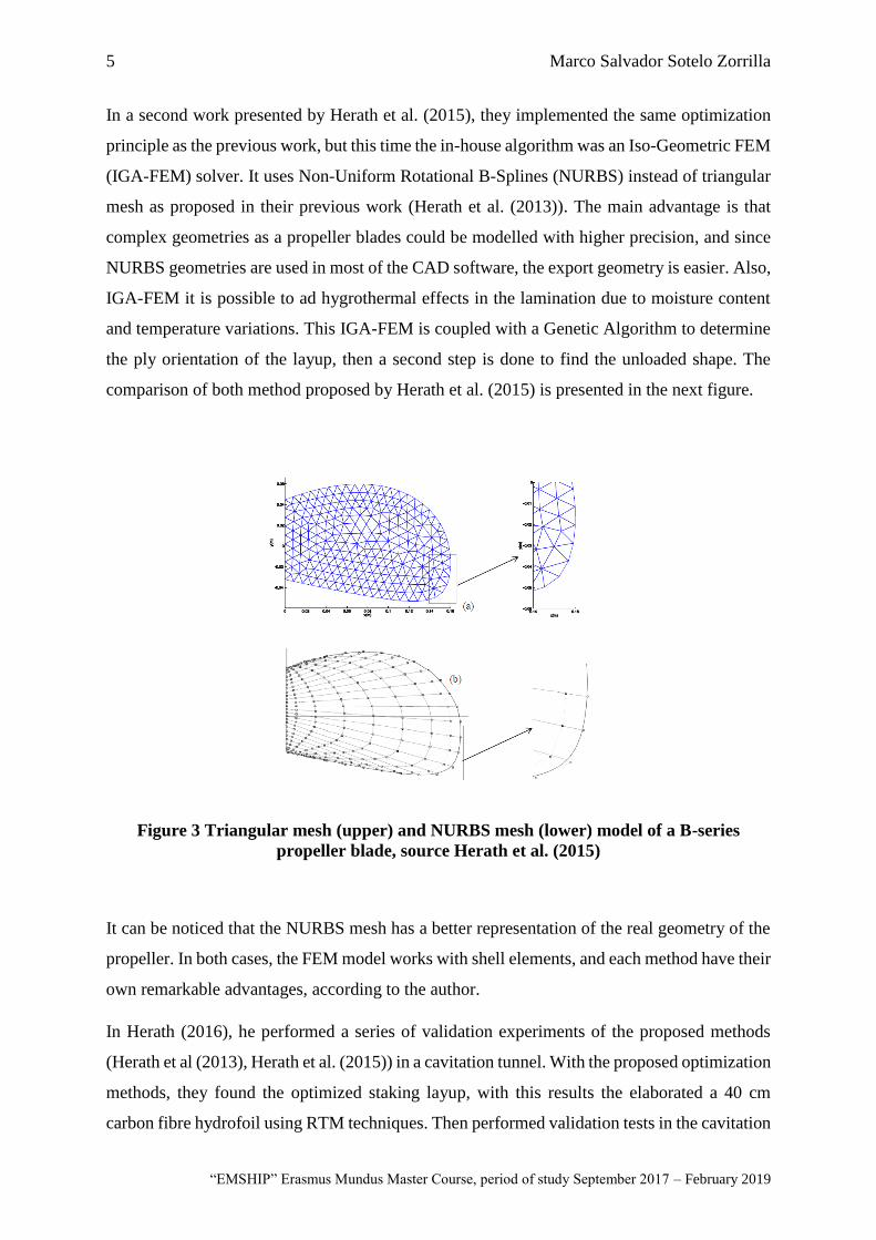
In a second work presented by Herath et al. (2015), they implemented the same optimization
principle as the previous work, but this time the in-house algorithm was an Iso-Geometric FEM
(IGA-FEM) solver. It uses Non-Uniform Rotational B-Splines (NURBS) instead of triangular
mesh as proposed in their previous work (Herath et al. (2013)). The main advantage is that
complex geometries as a propeller blades could be modelled with higher precision, and since
NURBS geometries are used in most of the CAD software, the export geometry is easier. Also,
IGA-FEM it is possible to ad hygrothermal effects in the lamination due to moisture content
and temperature variations. This IGA-FEM is coupled with a Genetic Algorithm to determine
the ply orientation of the layup, then a second step is done to find the unloaded shape. The
comparison of both method proposed by Herath et al. (2015) is presented in the next figure.
Figure 3 Triangular mesh (upper) and NURBS mesh (lower) model of a B-series
propeller blade, source Herath et al. (2015)
It can be noticed that the NURBS mesh has a better representation of the real geometry of the
propeller. In both cases, the FEM model works with shell elements, and each method have their
own remarkable advantages, according to the author.
In Herath (2016), he performed a series of validation experiments of the proposed methods
(Herath et al (2013), Herath et al. (2015)) in a cavitation tunnel. With the proposed optimization
methods, they found the optimized staking layup, with this results the elaborated a 40 cm
carbon fibre hydrofoil using RTM techniques. Then performed validation tests in the cavitation
6 Automated manufacture of shape-adaptive large hydrofoil
Master Thesis developed at University of New South Wales, Australia; and at University of Rostock, Germany
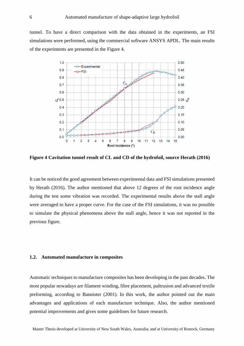
tunnel. To have a direct comparison with the data obtained in the experiments, an FSI
simulations were performed, using the commercial software ANSYS APDL. The main results
of the experiments are presented in the Figure 4.
Figure 4 Cavitation tunnel result of CL and CD of the hydrofoil, source Herath (2016)
It can be noticed the good agreement between experimental data and FSI simulations presented
by Herath (2016). The author mentioned that above 12 degrees of the root incidence angle
during the test some vibration was recorded. The experimental results above the stall angle
were averaged to have a proper curve. For the case of the FSI simulations, it was no possible
to simulate the physical phenomena above the stall angle, hence it was not reported in the
previous figure.
1.2. Automated manufacture in composites
Automatic techniques to manufacture composites has been developing in the past decades. The
most popular nowadays are filament winding, fibre placement, pultrusion and advanced textile
preforming, according to Bannister (2001). In this work, the author pointed out the main
advantages and applications of each manufacture technique. Also, the author mentioned
potential improvements and gives some guidelines for future research.
7 Marco Salvador Sotelo Zorrilla
“EMSHIP” Erasmus Mundus Master Course, period of study September 2017 – February 2019
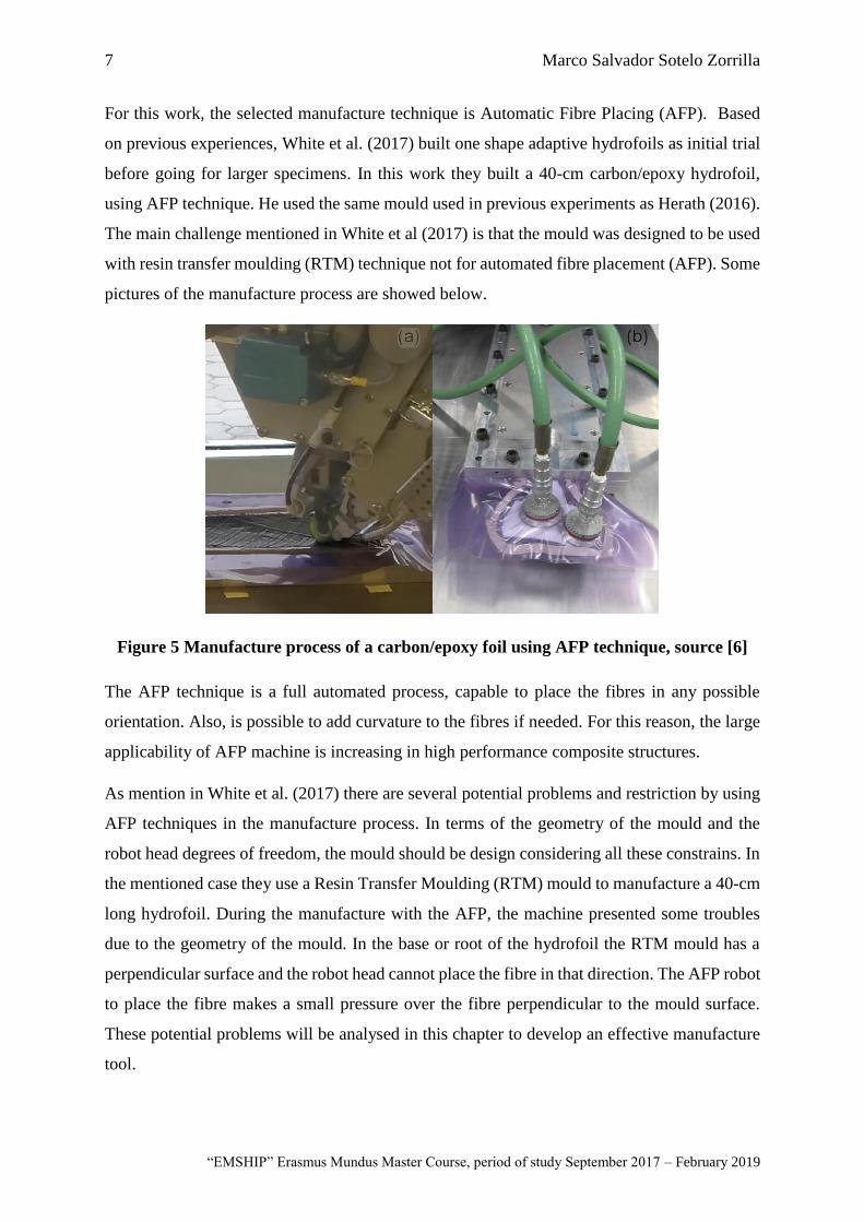
For this work, the selected manufacture technique is Automatic Fibre Placing (AFP). Based
on previous experiences, White et al. (2017) built one shape adaptive hydrofoils as initial trial
before going for larger specimens. In this work they built a 40-cm carbon/epoxy hydrofoil,
using AFP technique. He used the same mould used in previous experiments as Herath (2016).
The main challenge mentioned in White et al (2017) is that the mould was designed to be used
with resin transfer moulding (RTM) technique not for automated fibre placement (AFP). Some
pictures of the manufacture process are showed below.
Figure 5 Manufacture process of a carbon/epoxy foil using AFP technique, source [6]
The AFP technique is a full automated process, capable to place the fibres in any possible
orientation. Also, is possible to add curvature to the fibres if needed. For this reason, the large
applicability of AFP machine is increasing in high performance composite structures.
As mention in White et al. (2017) there are several potential problems and restriction by using
AFP techniques in the manufacture process. In terms of the geometry of the mould and the
robot head degrees of freedom, the mould should be design considering all these constrains. In
the mentioned case they use a Resin Transfer Moulding (RTM) mould to manufacture a 40-cm
long hydrofoil. During the manufacture with the AFP, the machine presented some troubles
due to the geometry of the mould. In the base or root of the hydrofoil the RTM mould has a
perpendicular surface and the robot head cannot place the fibre in that direction. The AFP robot
to place the fibre makes a small pressure over the fibre perpendicular to the mould surface.
These potential problems will be analysed in this chapter to develop an effective manufacture
tool.

8 Automated manufacture of shape-adaptive large hydrofoil
Master Thesis developed at University of New South Wales, Australia; and at University of Rostock, Germany
1.3. Thick laminate manufacture
The curing cycle of polymer matrix composites is a critical phase in the manufacture process
of composite structures. Due to the diversity of manufacture techniques, matrices, fibre types
and formats it is complex to achieve or determine the real mechanical properties of the final
product. For thick laminates, the complete cure of all inner layers is a task complicated to
achieve. The main difficulty with thick laminates is the longer curing cycle required to cure
completely. Longer curing cycles will induce higher levels of residual stresses and therefore
higher risk of micro mechanical problems. The typical issues coming from high residual
stresses during the curing cycle are induced warpage, fibre buckling, matrix micro-cracking
and delamination, according to Campbell (2003).
In this work will be studied the curing cycle of the large hydrofoil, considered as a thick
laminate (around 20 mm). The material to manufacture the foil will carbon/epoxy prepreg with
AFP technique with Autoclave curing. The methodology that will be used to determine the
curing cycle is proposed by Gower et al. (2016). In this reference, the author recommends
having a longer curing cycle with gradual increment on the temperature rate in the Autoclave.
The pressure inside the Autoclave is recommended to be constant during all the curing cycle.
The proposed method is presented in the following figure.
9 Marco Salvador Sotelo Zorrilla
“EMSHIP” Erasmus Mundus Master Course, period of study September 2017 – February 2019
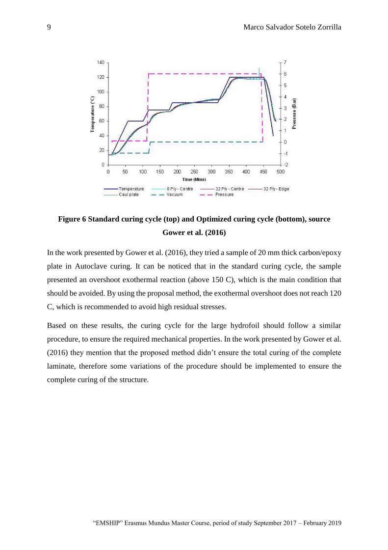
Figure 6 Standard curing cycle (top) and Optimized curing cycle (bottom), source
Gower et al. (2016)
In the work presented by Gower et al. (2016), they tried a sample of 20 mm thick carbon/epoxy
plate in Autoclave curing. It can be noticed that in the standard curing cycle, the sample
presented an overshoot exothermal reaction (above 150 C), which is the main condition that
should be avoided. By using the proposal method, the exothermal overshoot does not reach 120
C, which is recommended to avoid high residual stresses.
Based on these results, the curing cycle for the large hydrofoil should follow a similar
procedure, to ensure the required mechanical properties. In the work presented by Gower et al.
(2016) they mention that the proposed method didn’t ensure the total curing of the complete
laminate, therefore some variations of the procedure should be implemented to ensure the
complete curing of the structure.
10 Automated manufacture of shape-adaptive large hydrofoil
Master Thesis developed at University of New South Wales, Australia; and at University of Rostock, Germany
1.4. Sensors for control of composite structures
Many experiments have been carried out to measurement the influence of the hydroelasticity
of the foils. In work presented by Ducoin et al. (2012, Wu et al. (2015) and Zarruk et al. (2014)
they tested flexible hydrofoils in cavitation tunnel. In those works, the measured the influence
of the hydroelastic properties of the foil not only in lift/drag variation but also in cavitation
generation and behaviour in turbulent flows. They technique used to measure the deformation
in those works was with tracking the tip with high resolution cameras.
In the work presented by Giovannetti (2016) she performed test in a wind tunnel of a sandwich
composite hydrofoil. To study the flow around the foil and the fluid-structure interaction she
used a PIV (Particle Image Velocimetry). This test was part of the validation of the numerical
method proposed to study the FSI behaviour of composite tailored specimens with different
internal structures.
In all the previous work the studied the behaviour of the fluid around a hydroelastic foil and
the dynamical deformation of the foil by image recording devices and cameras. Even if this
measurement method is accurate enough, it is only possible to record the information of the tip
displacement and twist. Other measurement methods like embedded optic fibres is possible to
measure large part of the strains and stresses along the hydrofoil, without disturbing the
surrounding flow.
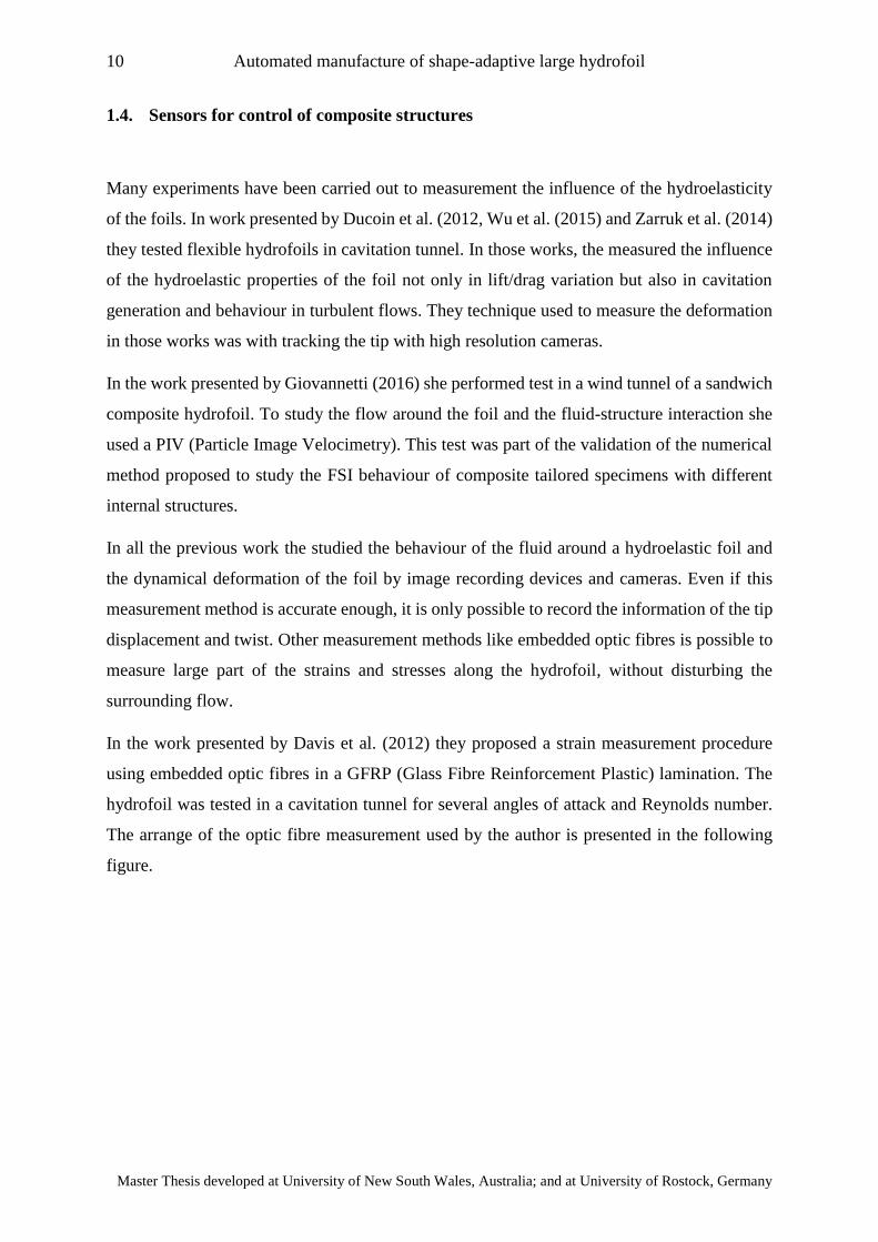
In the work presented by Davis et al. (2012) they proposed a strain measurement procedure
using embedded optic fibres in a GFRP (Glass Fibre Reinforcement Plastic) lamination. The
hydrofoil was tested in a cavitation tunnel for several angles of attack and Reynolds number.
The arrange of the optic fibre measurement used by the author is presented in the following
figure.
11 Marco Salvador Sotelo Zorrilla
“EMSHIP” Erasmus Mundus Master Course, period of study September 2017 – February 2019
It can be noticed in the previous figure that they used 4 independent fibres two for bottom and
other two for top face. On each face of the foil they placed sensors in the leading and trailing
edge to measure the twist during the trials. In this reference they only performed test to prove
that was possible to measure the strain by using embedded fibre technique.
Davis et al. (2018), presented an experimental comparison between foil strain gauges and
distributed optical fibre sensors. In their experiments they compared strain response, special
resolution and noise level. The experiments were performed first on a small specimen with
fatigue-induced cracks and secondly in a full-scale sample fatigue test. In general, the results
obtained using both measurement methods were quite similar, however distributed optical
fibres presents some limitations when measuring in regions with high strain gradients.
Figure 7 Sensor placing in the hydrofoil, source Davis et al. (2012)
12 Automated manufacture of shape-adaptive large hydrofoil
Master Thesis developed at University of New South Wales, Australia; and at University of Rostock, Germany
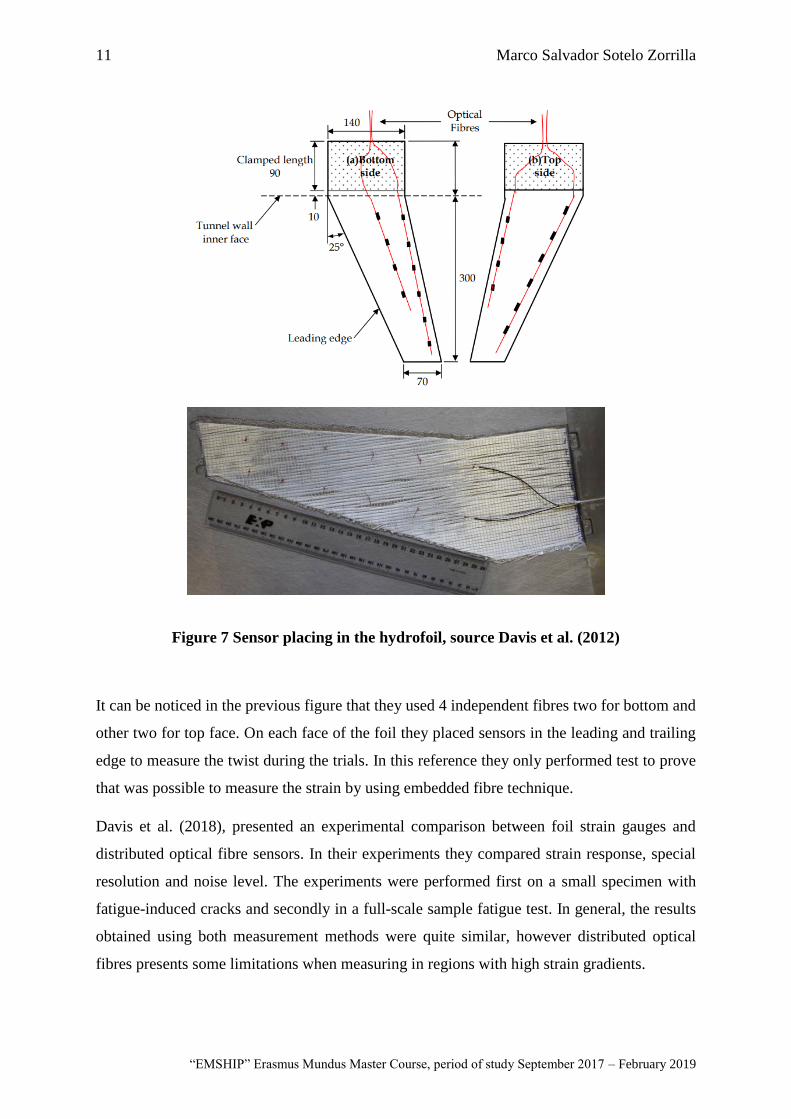
Figure 8 Embedded fibre in a CFRP hydrofoil, source Maung et al. (2015)
In the work presented by Maung et al. (2015) they proposed other arrangement of the optic
fibre measurement in a CFRP hydrofoil. The filament arrangement can be appreciated in the
following figure.
The strain measurement was validated with the commercial FEM code ANSYS. The hydrofoil
was designed and calculated by the method proposed by Herath et al. (2015). The load used in
this test was a quasi-static load in centre of pressure of the hydrofoil. The strain and stresses
measured along the optic fibre were compared with the FEM model. The result is presented in
the following figure
13 Marco Salvador Sotelo Zorrilla
“EMSHIP” Erasmus Mundus Master Course, period of study September 2017 – February 2019
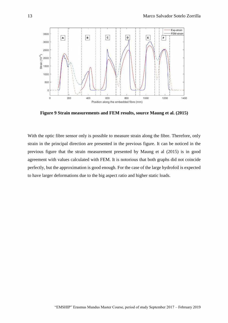
Figure 9 Strain measurements and FEM results, source Maung et al. (2015)
With the optic fibre sensor only is possible to measure strain along the fibre. Therefore, only
strain in the principal direction are presented in the previous figure. It can be noticed in the
previous figure that the strain measurement presented by Maung et al (2015) is in good
agreement with values calculated with FEM. It is notorious that both graphs did not coincide
perfectly, but the approximation is good enough. For the case of the large hydrofoil is expected
to have larger deformations due to the big aspect ratio and higher static loads.

14 Automated manufacture of shape-adaptive large hydrofoil
Master Thesis developed at University of New South Wales, Australia; and at University of Rostock, Germany
This page is intentionally left blank.
15 Marco Salvador Sotelo Zorrilla
“EMSHIP” Erasmus Mundus Master Course, period of study September 2017 – February 2019
1.5. Methodology
This work is manly experimental based. A large flexible hydrofoil will be design and
manufacture with carbon/epoxy prepreg and cured in autoclave. In the first chapter will be
explained the design process of the lamination of the large hydrofoil. This chapter is intended
to determine the ply orientation of the lamination to achieve the required flexibility on the
hydrofoil, by using the method proposed by Herath et al. (2014). The mentioned method
includes a coupled FEM and Genetic Algorithm solver. Using as design variables the ply
orientation, it is possible to obtain the layup that will achieve the required level of flexibility
for the large hydrofoil.
The second chapter will explain the procedure for the development of the manufacture tool to
produce the large hydrofoil using the AFP technique. This chapter will explain the manufacture
constrains and potential challenges considered to produce the large hydrofoil. Based on
previous experiences as mentioned in White et al. (2017) to avoid potential problems during
the manufacture, working space and laminate orientation are key parameters to consider. In
this chapter the manufacture tool will be coded, and the mould will be produce considering
potential manufacture problems and the robot constrains.
The third chapter is intended to study the curing cycle of the laminate. Thermoset materials,
like carbon/epoxy laminations have interlaminate curing cycle that are given by the
manufacturer of the components. For the construction of the large hydrofoil a carbon/epoxy
prepreg will be used, cured in Autoclave. Therefore, the curing cycle needs to be studied to
ensure that innermost plies of large hydrofoil are properly cured after the Autoclave curing
cycle. The goal of a correct study of the curing cycle of the lamination will ensure that the
hydrofoil will achieve the expected mechanical properties, as mentioned in Gower et al. (2016).
The thick laminate curing study is important to understand how temperature change occurs at
different thickness level during the cure cycle, and it will be useful for future manufacture of
thick hydrofoil.
In the final chapter will be proposed a monitoring procedure to measure the strain and
deformation on the large hydrofoil. This work will be focused on embedded optic fibre strain
measurement technique. In this chapter will be discussed and proposed the ideal location of the
optic fibres in the laminate to measure the interest strain and twist in the hydrofoil. This
procedure should be included as an intermediate step in the manufacture process because the
embedded optic fibre will be placed inside the lamination.

16 Automated manufacture of shape-adaptive large hydrofoil
Master Thesis developed at University of New South Wales, Australia; and at University of Rostock, Germany
This page is intentionally left blank.
17 Marco Salvador Sotelo Zorrilla
“EMSHIP” Erasmus Mundus Master Course, period of study September 2017 – February 2019
CHAPER 2
Design and optimization of the large hydrofoil
2.1. Introduction
The usage of composite material in marine and naval applications has increased significantly
in the last years. Composites materials can be used to build the complete hull, but also are
becoming very popular in the manufacture special devices as keels, rudders, bilge keels,
hydrofoils, etc. With the potential improvement of marine propellers by using composite
materials, many research centres around the world had studied new ways to design and
optimize propeller blades with composite materials (Lin and Lee (2004), Young et al. (2016),
Mulcahy (2013), Herath (2015)). The Defence Science and Technology Group (DSTG), from
the Department of Defence of Australia, built a scale propeller blade for research purpose. To
avoid dealing with the complex geometry of a propeller blade shape, they decided to build a
large hydrofoil with a symmetrical foil section. This hydrofoil represented the simplified form
of a marine propeller blade. The device was 1.5 m long, 500 mm wide in the root and 100 mm
as maximum thickness, according to Phillips et al. (2014). The geometry of the hydrofoil is
presented in the following figure.
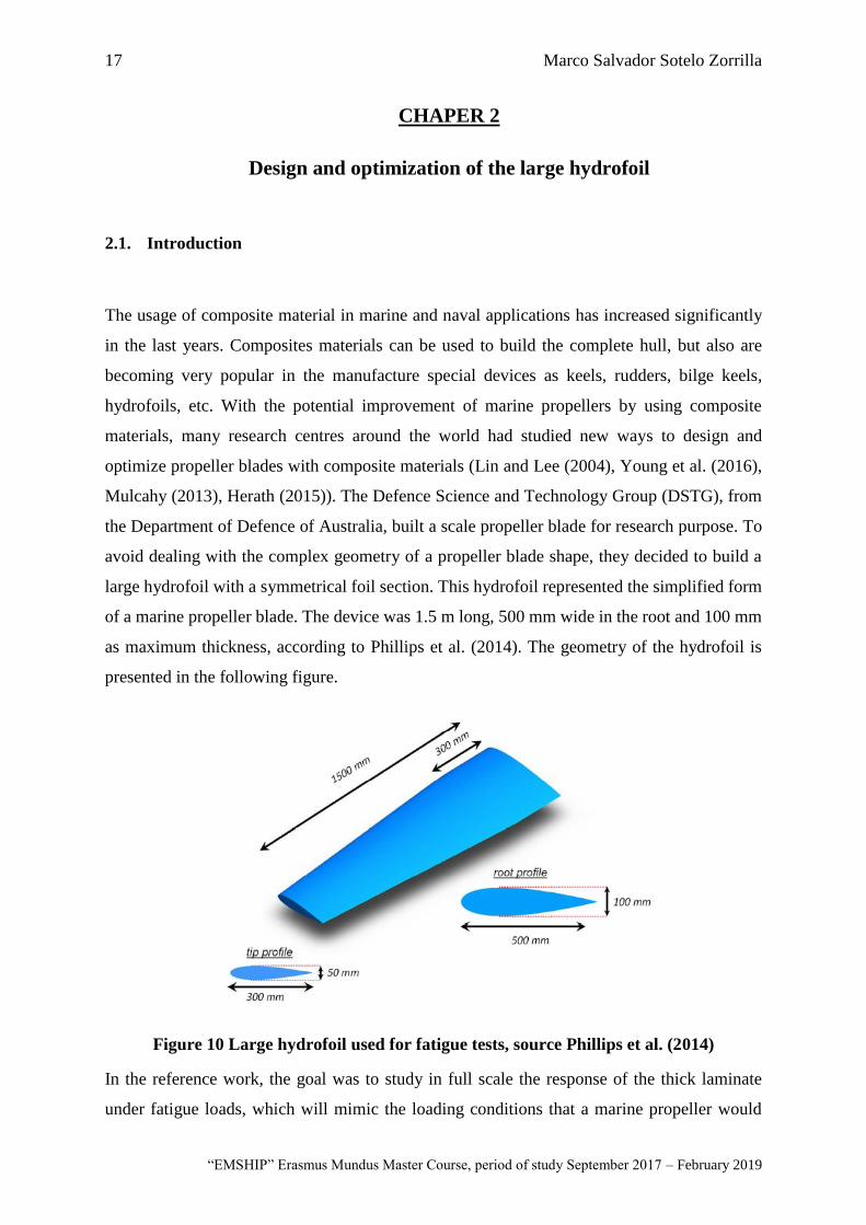
Figure 10 Large hydrofoil used for fatigue tests, source Phillips et al. (2014)
In the reference work, the goal was to study in full scale the response of the thick laminate
under fatigue loads, which will mimic the loading conditions that a marine propeller would
18 Automated manufacture of shape-adaptive large hydrofoil
Master Thesis developed at University of New South Wales, Australia; and at University of Rostock, Germany
have during its operating life. The particularity of the reference hydrofoil was that the
manufacturing technique used was Resin Transfer Moulding (RTM) techniques.
In this work, the main dimensions of the reference hydrofoil will remain the same, but as the
manufacturing technique is different, a slight modification in the geometry was considered.
The hydrofoil built by Phillips et al. (2014) was a hybrid construction of a glass/epoxy core
and a carbon/epoxy skin. In this work, the same construction had been adopted. The geometry
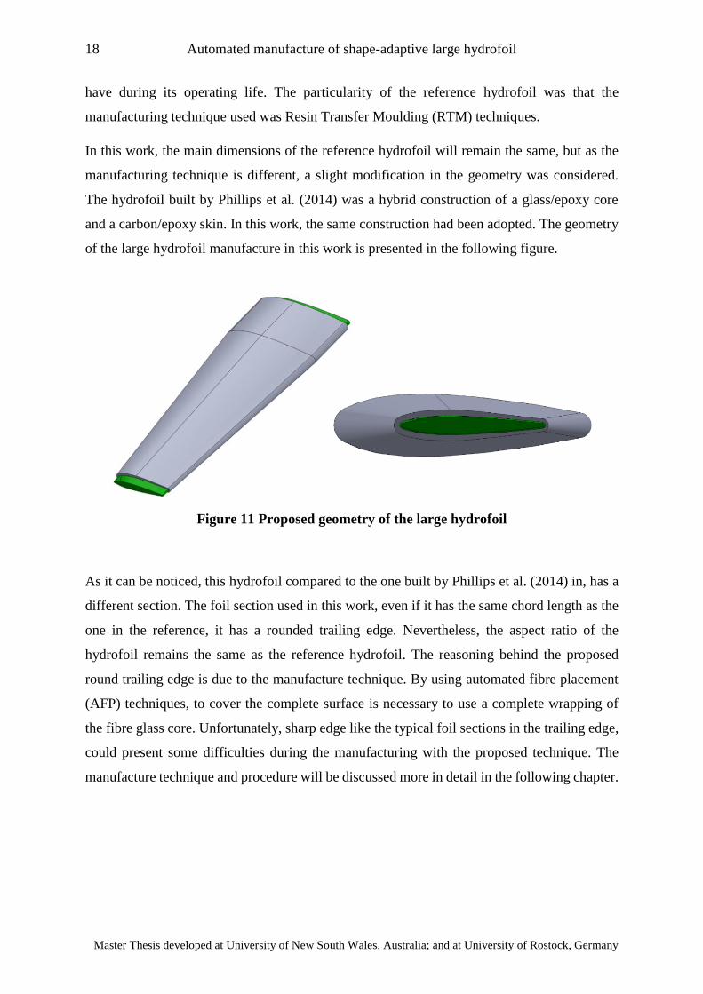
of the large hydrofoil manufacture in this work is presented in the following figure.
As it can be noticed, this hydrofoil compared to the one built by Phillips et al. (2014) in, has a
different section. The foil section used in this work, even if it has the same chord length as the
one in the reference, it has a rounded trailing edge. Nevertheless, the aspect ratio of the
hydrofoil remains the same as the reference hydrofoil. The reasoning behind the proposed
round trailing edge is due to the manufacture technique. By using automated fibre placement
(AFP) techniques, to cover the complete surface is necessary to use a complete wrapping of
the fibre glass core. Unfortunately, sharp edge like the typical foil sections in the trailing edge,
could present some difficulties during the manufacturing with the proposed technique. The
manufacture technique and procedure will be discussed more in detail in the following chapter.
Figure 11 Proposed geometry of the large hydrofoil
19 Marco Salvador Sotelo Zorrilla
“EMSHIP” Erasmus Mundus Master Course, period of study September 2017 – February 2019
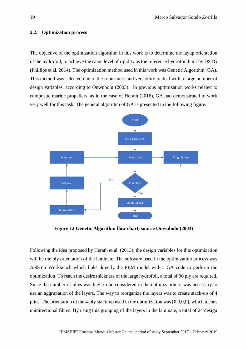
2.2. Optimization process
The objective of the optimization algorithm in this work is to determine the layup orientation
of the hydrofoil, to achieve the same level of rigidity as the reference hydrofoil built by DSTG
(Phillips et al. 2014). The optimization method used in this work was Genetic Algorithm (GA).
This method was selected due to the robustness and versatility to deal with a large number of
design variables, according to Onwubolu (2003). In previous optimization works related to
composite marine propellers, as in the case of Herath (2016), GA had demonstrated to work
very well for this task. The general algorithm of GA is presented in the following figure.
Start
Initial population
Evaluation
Condition
END
Output result
Reproduction
Mutation
Crossover
Assign fitness
No
Yes
Figure 12 Genetic Algorithm flow chart, source Onwubolu (2003)
Following the idea proposed by Herath et al. (2013), the design variables for this optimization
will be the ply orientation of the laminate. The software used in the optimization process was
ANSYS Workbench which links directly the FEM model with a GA code to perform the
optimization. To reach the desire thickness of the large hydrofoil, a total of 96 ply are required.
Since the number of plies was high to be considered in the optimization, it was necessary to
use an aggrupation of the layers. The way to reorganize the layers was to create stack-up of 4
plies. The orientation of the 4-ply stack-up used in the optimization was [0,0,0,0], which means
unidirectional fibres. By using this grouping of the layers in the laminate, a total of 24 design
20 Automated manufacture of shape-adaptive large hydrofoil
Master Thesis developed at University of New South Wales, Australia; and at University of Rostock, Germany
variables were considered in the optimization, instead of 96, reducing significantly the
computational cost.
The design variables used in the optimisation, were considered as discrete variables. Even if
the orientation of the fibre or plies could be a real value or considered as continuum variable,
based on previous experiences recommended in Herath et al. (2013), it was decided to model
the orientation of the laminate as discrete variables to save computational time. Since each
layer is composed by unidirectional fibres, the possible values that the design variables could
take during the optimization was between 0 to 180 degrees with steps of 15 degrees.
Regarding the Genetic algorithm, the number of candidates per generation considered on each
evaluation was 51. This number is not a strict rule, but for such many design variables, it is
recommended to have a large number of initial population. On each generation, the 10 best
candidates that obtained the higher fitness were selected as parents to generate the next
generation. With a crossover technique of two points and a mutant factor of 1%, based on the
10 parents, the next generation of the population was developed. The stopping criteria for the
optimization was a relative error below 1.0% of the target values of deflection or stop after 100
generations, whichever is less. The recommended values for the optimization technique were
taken following the recommendation in Onwubolu (2003).
Objective function and design variables
As mentioned before, the large hydrofoil designed and manufactured in this project will be
submitted to the same types of tests as the one presented in the work of Phillips et al. (2014).
Hence, it was decided to set the objective function in order to get the same level of rigidity as
the counterpart hydrofoil. One easy way to achieve the same level of flexibility or rigidity in
the laminate is to set the objective function to a single target. In this work was selected as a
target the deformation in the tip of the hydrofoil in the leading and trailing edge. Those values
are presented in Phillips et al. (2014), as can be shown in the following figure.

21 Marco Salvador Sotelo Zorrilla
“EMSHIP” Erasmus Mundus Master Course, period of study September 2017 – February 2019
Figure 13 Experimental results of large hydrofoil, source Phillips et al. (2014)
It can be noticed that for a load of 28KN the deformation recorded during the experiments in
the leading edge was 40 mm and 42.5 mm for the trailing edge. The mentioned values will be
used as targets or objectives of the optimization process presented in this chapter.
2.3. Definition of the FEM model using Shell elements
The optimization process using GA is an iterative process that will solve on each generation
51 possible candidates of the population. Due to the large amount of simulations in the
optimization process, it was necessary to use a simplified model to reduce the simulation time.
The simplified model was built using shell elements. The assumption of the shell elements is
that all the thick laminate is modelled as a single equivalent shell element, reducing
significantly the number of nodes and elements. In this simplified model only the carbon skin
had been considered, because that is the main interest in the optimization. Without the fibre
glass core in the simplified model the total rigidity will be affected, therefore an adjustment in
the objective function must be consider
By using a simplified model, the simulation can converge rapidly but many phenomena like
interlaminate shear stresses and 3d stresses are not being considering. Those effects are
22 Automated manufacture of shape-adaptive large hydrofoil
Master Thesis developed at University of New South Wales, Australia; and at University of Rostock, Germany
considerable when the laminate is thick, therefore the results obtained from the shell model
cannot be considered for further analysis.
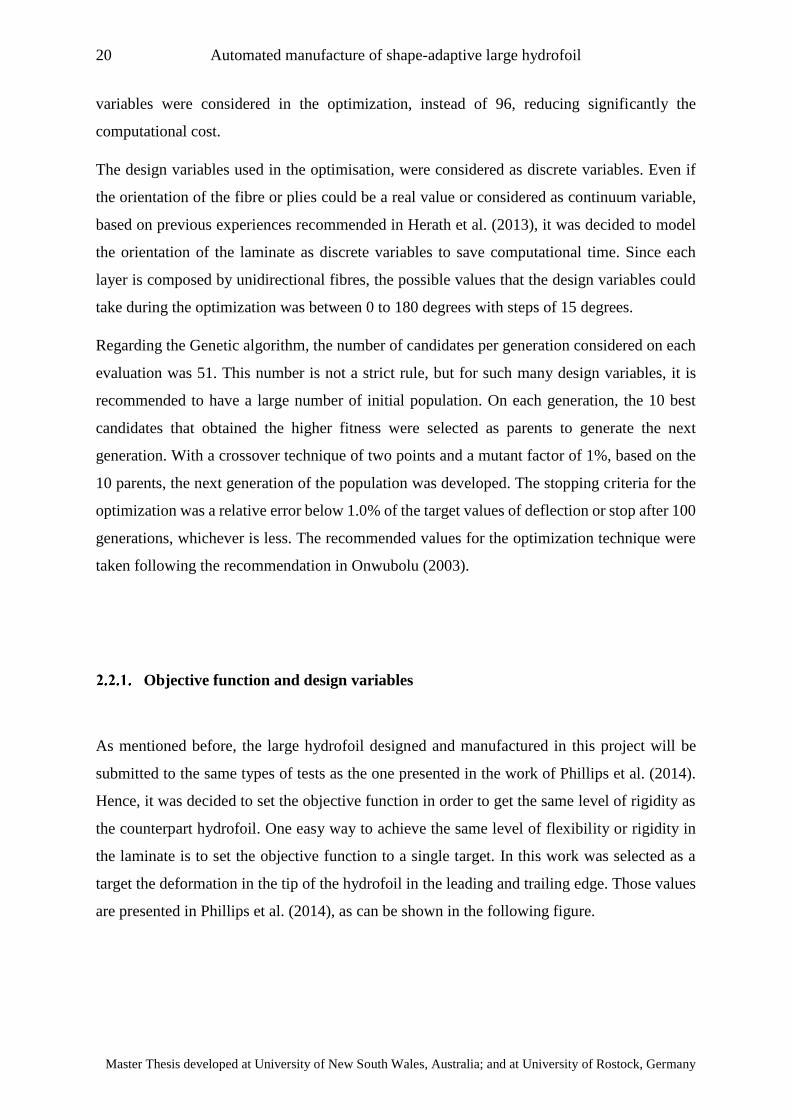
Geometrical model and mesh
As mentioned before, the geometrical model used for the optimization was the carbon skin
only, modelled as shell elements. To setup the finite element model, the first step is to input
the material data. For this case the material used was carbon epoxy prepreg E-752 with 35% of
resin content and with a dry weight of 145 grams per square meters, according to the
manufacturer (Park Advanced Composites Materials). The thickness of the material and
therefore of each layer used in this work was 0.2 mm wet and approximately 0.15 mm dry. The
mechanical properties of the construction material are presented in the following figure.
Figure 14 Material properties of the carbon/epoxy prepreg
The properties presented in the previous figure are for one single layer. For the optimization
will be used a stacking assumption of [0,0,0,0] which means 4 plies will be stack together in
the same direction. Therefore, the stacked or grouped material properties will not be different.
23 Marco Salvador Sotelo Zorrilla
“EMSHIP” Erasmus Mundus Master Course, period of study September 2017 – February 2019
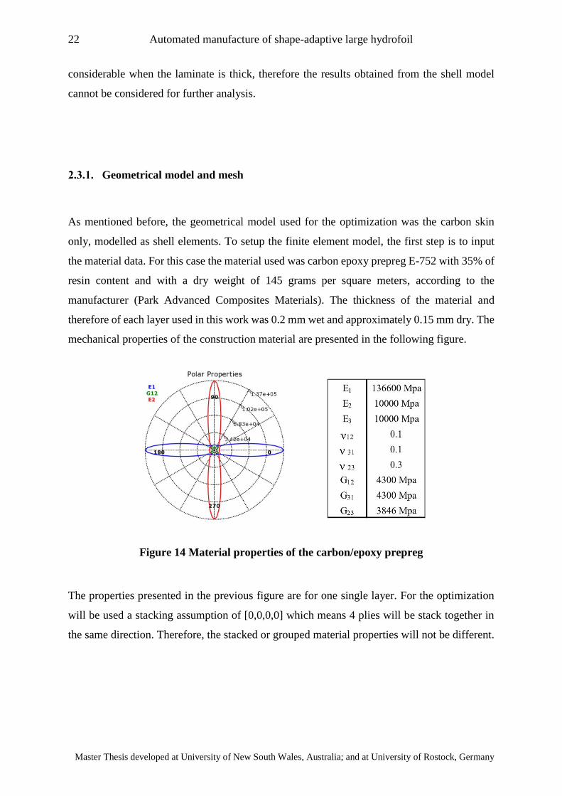
The following step is to define the layout of the hydrofoil. Since de carbon skin has not a
constant thickness through all the surface, it is necessary to define boundaries that will help to
achieve the desired final shape. The procedure used to define the boundaries was, starting from
the exterior surface of the carbon skin, generate thickness offset of each ply inwards the
reference geometry. Then the core geometry was used as a cutting tool. In this way was possible
to define the geometry of the boundaries that will be used in the manufacture process later.
This boundary generation process was done used the ACP(Pre) modulus of ANSYS
workbench. The generated boundaries will be used later in the manufacture process. The
thickness distribution of the hydrofoil is presented in the following figure.
Regarding the meshing of the model, due to the simplicity of the geometry a regular polygonal
mesh was selected for the analysis. A total of 36120 nodes and 36000 elements were used in
this simplified model. The mesh used for the optimization is presented in the following figure.
Figure 15 Geometry model of the hydrofoil using shell elements
24 Automated manufacture of shape-adaptive large hydrofoil
Master Thesis developed at University of New South Wales, Australia; and at University of Rostock, Germany
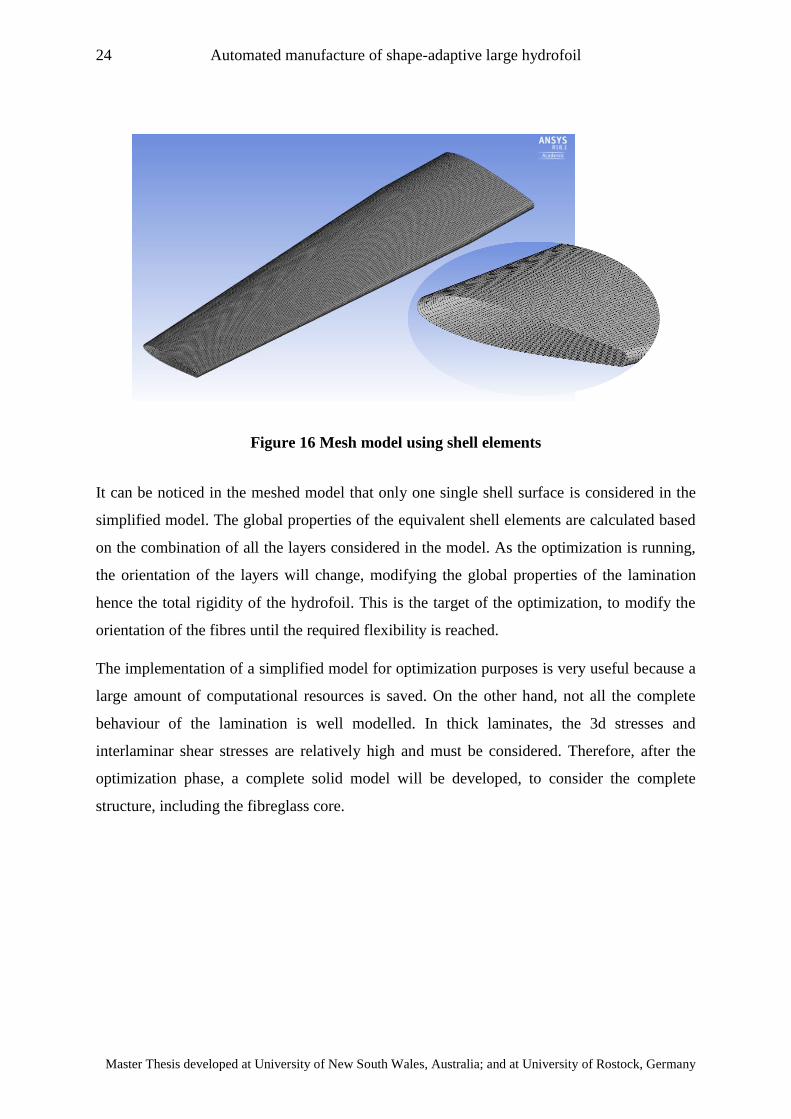
Figure 16 Mesh model using shell elements
It can be noticed in the meshed model that only one single shell surface is considered in the
simplified model. The global properties of the equivalent shell elements are calculated based
on the combination of all the layers considered in the model. As the optimization is running,
the orientation of the layers will change, modifying the global properties of the lamination
hence the total rigidity of the hydrofoil. This is the target of the optimization, to modify the
orientation of the fibres until the required flexibility is reached.
The implementation of a simplified model for optimization purposes is very useful because a
large amount of computational resources is saved. On the other hand, not all the complete
behaviour of the lamination is well modelled. In thick laminates, the 3d stresses and
interlaminar shear stresses are relatively high and must be considered. Therefore, after the
optimization phase, a complete solid model will be developed, to consider the complete
structure, including the fibreglass core.
25 Marco Salvador Sotelo Zorrilla
“EMSHIP” Erasmus Mundus Master Course, period of study September 2017 – February 2019
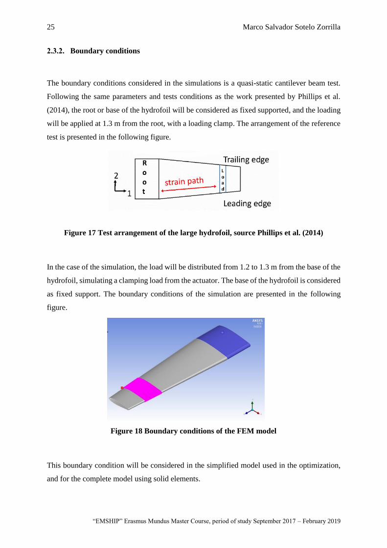
Boundary conditions
The boundary conditions considered in the simulations is a quasi-static cantilever beam test.
Following the same parameters and tests conditions as the work presented by Phillips et al.
(2014), the root or base of the hydrofoil will be considered as fixed supported, and the loading
will be applied at 1.3 m from the root, with a loading clamp. The arrangement of the reference
test is presented in the following figure.
Figure 17 Test arrangement of the large hydrofoil, source Phillips et al. (2014)
In the case of the simulation, the load will be distributed from 1.2 to 1.3 m from the base of the
hydrofoil, simulating a clamping load from the actuator. The base of the hydrofoil is considered
as fixed support. The boundary conditions of the simulation are presented in the following
figure.
This boundary condition will be considered in the simplified model used in the optimization,
and for the complete model using solid elements.
Figure 18 Boundary conditions of the FEM model
26 Automated manufacture of shape-adaptive large hydrofoil
Master Thesis developed at University of New South Wales, Australia; and at University of Rostock, Germany
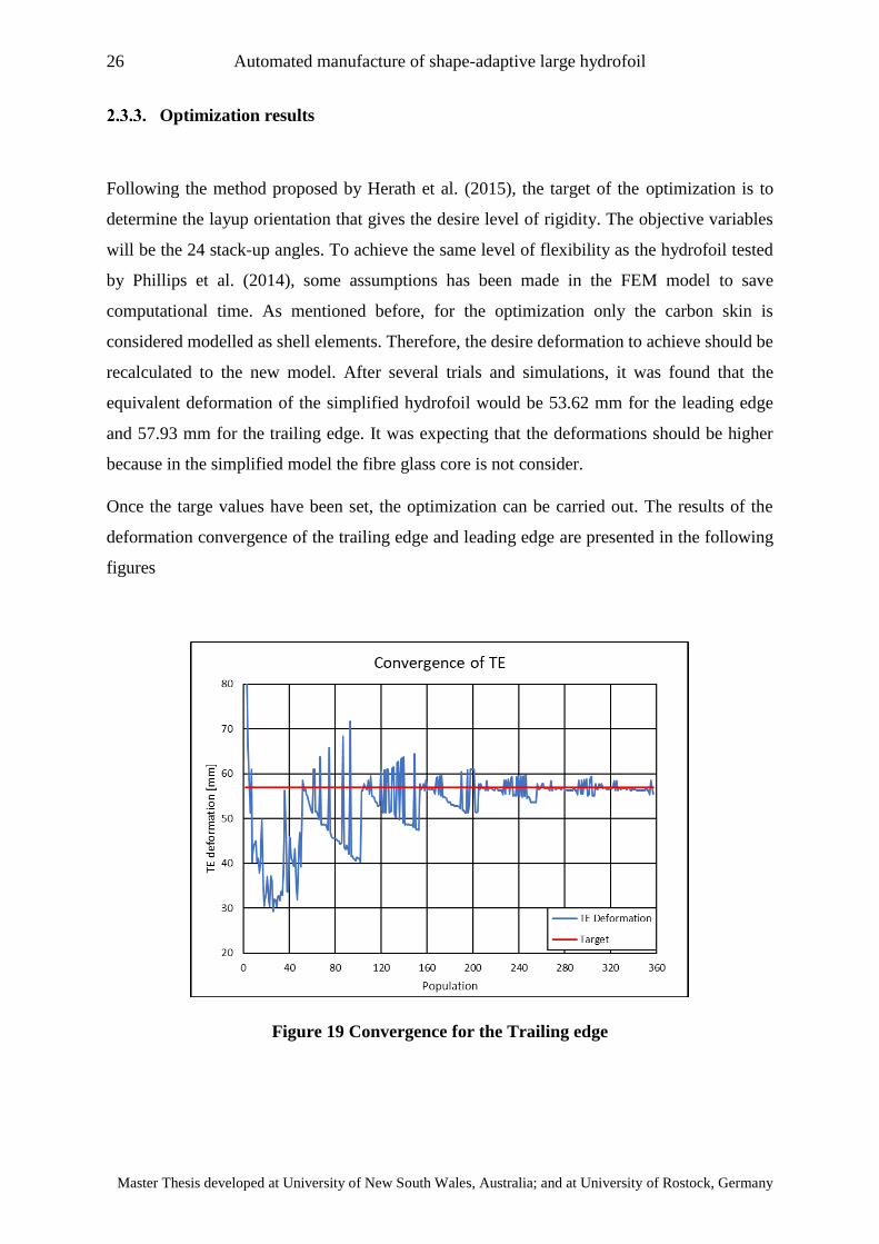
Optimization results
Following the method proposed by Herath et al. (2015), the target of the optimization is to
determine the layup orientation that gives the desire level of rigidity. The objective variables
will be the 24 stack-up angles. To achieve the same level of flexibility as the hydrofoil tested
by Phillips et al. (2014), some assumptions has been made in the FEM model to save
computational time. As mentioned before, for the optimization only the carbon skin is
considered modelled as shell elements. Therefore, the desire deformation to achieve should be
recalculated to the new model. After several trials and simulations, it was found that the
equivalent deformation of the simplified hydrofoil would be 53.62 mm for the leading edge
and 57.93 mm for the trailing edge. It was expecting that the deformations should be higher
because in the simplified model the fibre glass core is not consider.
Once the targe values have been set, the optimization can be carried out. The results of the
deformation convergence of the trailing edge and leading edge are presented in the following
figures
Figure 19 Convergence for the Trailing edge
27 Marco Salvador Sotelo Zorrilla
“EMSHIP” Erasmus Mundus Master Course, period of study September 2017 – February 2019
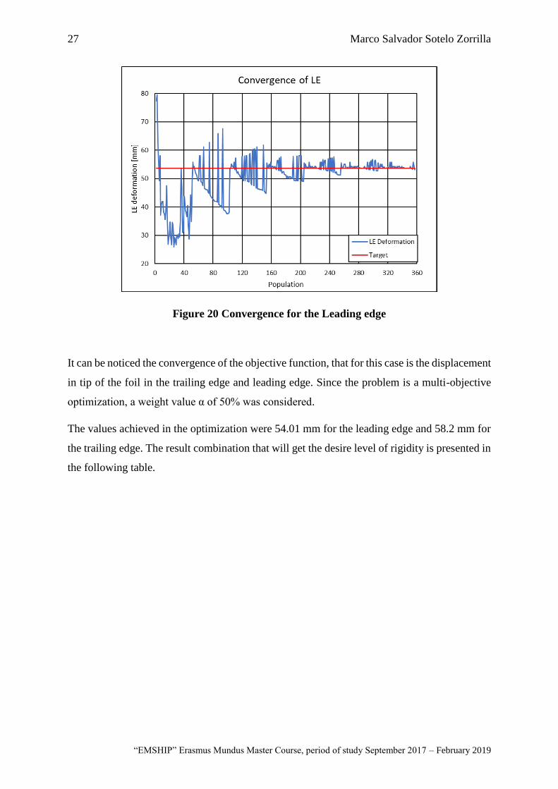
Figure 20 Convergence for the Leading edge
It can be noticed the convergence of the objective function, that for this case is the displacement
in tip of the foil in the trailing edge and leading edge. Since the problem is a multi-objective
optimization, a weight value α of 50% was considered.
The values achieved in the optimization were 54.01 mm for the leading edge and 58.2 mm for
the trailing edge. The result combination that will get the desire level of rigidity is presented in
the following table.
28 Automated manufacture of shape-adaptive large hydrofoil
Master Thesis developed at University of New South Wales, Australia; and at University of Rostock, Germany
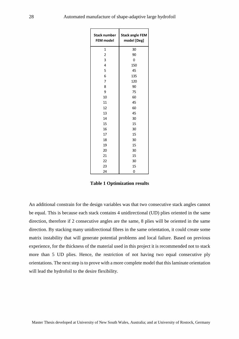
Table 1 Optimization results
An additional constrain for the design variables was that two consecutive stack angles cannot
be equal. This is because each stack contains 4 unidirectional (UD) plies oriented in the same
direction, therefore if 2 consecutive angles are the same, 8 plies will be oriented in the same
direction. By stacking many unidirectional fibres in the same orientation, it could create some
matrix instability that will generate potential problems and local failure. Based on previous
experience, for the thickness of the material used in this project it is recommended not to stack
more than 5 UD plies. Hence, the restriction of not having two equal consecutive ply
orientations. The next step is to prove with a more complete model that this laminate orientation
will lead the hydrofoil to the desire flexibility.
Stack number
FEM model
Stack angle FEM
model [Deg]
1 30
2 90
3 0
4 150
5 45
6 135
7 120
8 90
9 75
10 60
11 45
12 60
13 45
14 30
15 15
16 30
17 15
18 30
19 15
20 30
21 15
22 30
23 15
24 0
29 Marco Salvador Sotelo Zorrilla
“EMSHIP” Erasmus Mundus Master Course, period of study September 2017 – February 2019
2.4. Solution of the FEM using solid elements
To have a better model of the phenomena, a higher accurate method is needed. When working
with thick laminates, the 3D stresses trough the thickness of the composite becomes important.
Also inter laminar shear stresses should be considered, even more when the thick laminate if
compose by many layers.
For all this reason, once the optimization phase has been performed, the resulting layup
orientation will be used as an input for the solid models. For the case of the solid model, the
fibre glass core is considering. The way to deal with the interface between the carbon skin and
FG core is to assume a bounded contact surface. By using bounded contact surface, it means
that at the interface neither of the two materials can penetrate the other one and both will be
stick together. It is expected to have large shear stresses at the interface due to the difference
in the strength of both materials.
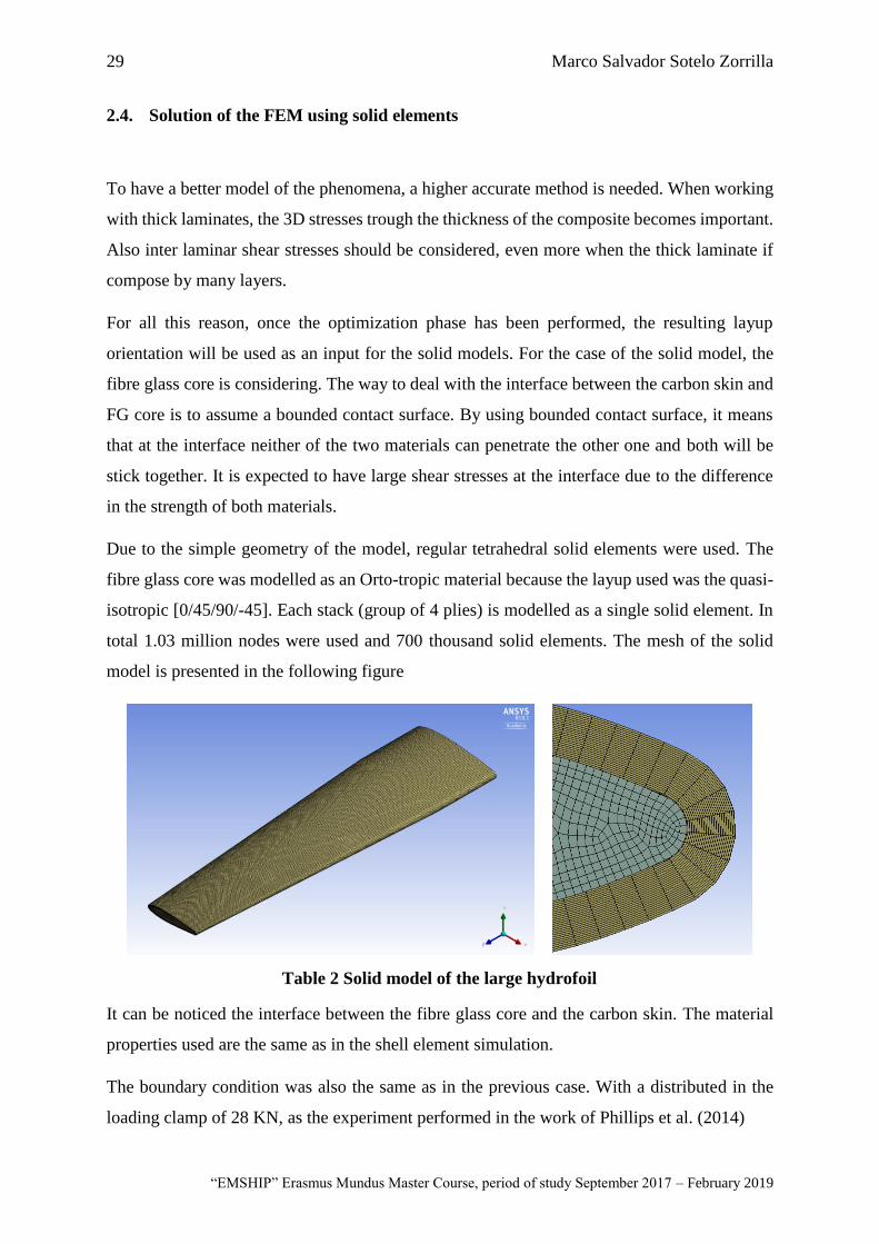
Due to the simple geometry of the model, regular tetrahedral solid elements were used. The
fibre glass core was modelled as an Orto-tropic material because the layup used was the quasi-
isotropic [0/45/90/-45]. Each stack (group of 4 plies) is modelled as a single solid element. In
total 1.03 million nodes were used and 700 thousand solid elements. The mesh of the solid
model is presented in the following figure
It can be noticed the interface between the fibre glass core and the carbon skin. The material
properties used are the same as in the shell element simulation.
The boundary condition was also the same as in the previous case. With a distributed in the
loading clamp of 28 KN, as the experiment performed in the work of Phillips et al. (2014)
Table 2 Solid model of the large hydrofoil
30 Automated manufacture of shape-adaptive large hydrofoil
Master Thesis developed at University of New South Wales, Australia; and at University of Rostock, Germany
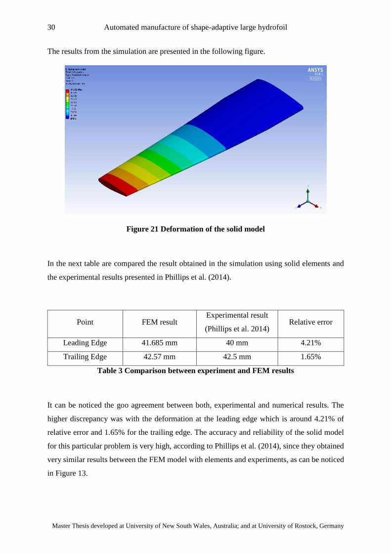
The results from the simulation are presented in the following figure.
Figure 21 Deformation of the solid model
In the next table are compared the result obtained in the simulation using solid elements and
the experimental results presented in Phillips et al. (2014).
Point FEM result Experimental result
(Phillips et al. 2014) Relative error
Leading Edge 41.685 mm 40 mm 4.21%
Trailing Edge 42.57 mm 42.5 mm 1.65%
Table 3 Comparison between experiment and FEM results
It can be noticed the goo agreement between both, experimental and numerical results. The
higher discrepancy was with the deformation at the leading edge which is around 4.21% of
relative error and 1.65% for the trailing edge. The accuracy and reliability of the solid model
for this particular problem is very high, according to Phillips et al. (2014), since they obtained
very similar results between the FEM model with elements and experiments, as can be noticed
in Figure 13.

31 Marco Salvador Sotelo Zorrilla
“EMSHIP” Erasmus Mundus Master Course, period of study September 2017 – February 2019
CHAPTER 3
Development of the manufacture tool and construction of the hydrofoil
3.1. Introduction to automatic fibre placement techniques
Composites materials have demonstrated many advantages and large variety of applications in
different fields of engineering. Most of modern large aircraft like the Airbus A350 and Boeing
787 have around 50% of their weight in composites components, according to Coriolis
Composites (2015). Due to the increase demand of high quality a fast productivity, specially
pushed by the aerospace and aeronautic industry, many automated manufacturing techniques
for composites material have been developed in the last decades.
One of the most used is the Automated Fibre Placement (AFP) technique which is considered
as an advance manufacture technique for composites material. This method consists in a robot
head that place prepreg tows in the mould or mandrel in a desire orientation. The method is
fully automated, and no need of expert operators is required. Due to the automated control in
the deposition material during the lamination, it is possible to achieve higher quality products
compared to traditional manufacturing techniques as Vacuum Assisted Resin Infusion (VARI),
Resin Transfer Moulding (RTM) and manual layup, according to Kozaczuk (2016).
The most common material used with AFP techniques are carbo/epoxy prepregs that will be
cured in autoclave. An example of AFP techniques during manufacture is presented in the
following figure.
32 Automated manufacture of shape-adaptive large hydrofoil
Master Thesis developed at University of New South Wales, Australia; and at University of Rostock, Germany
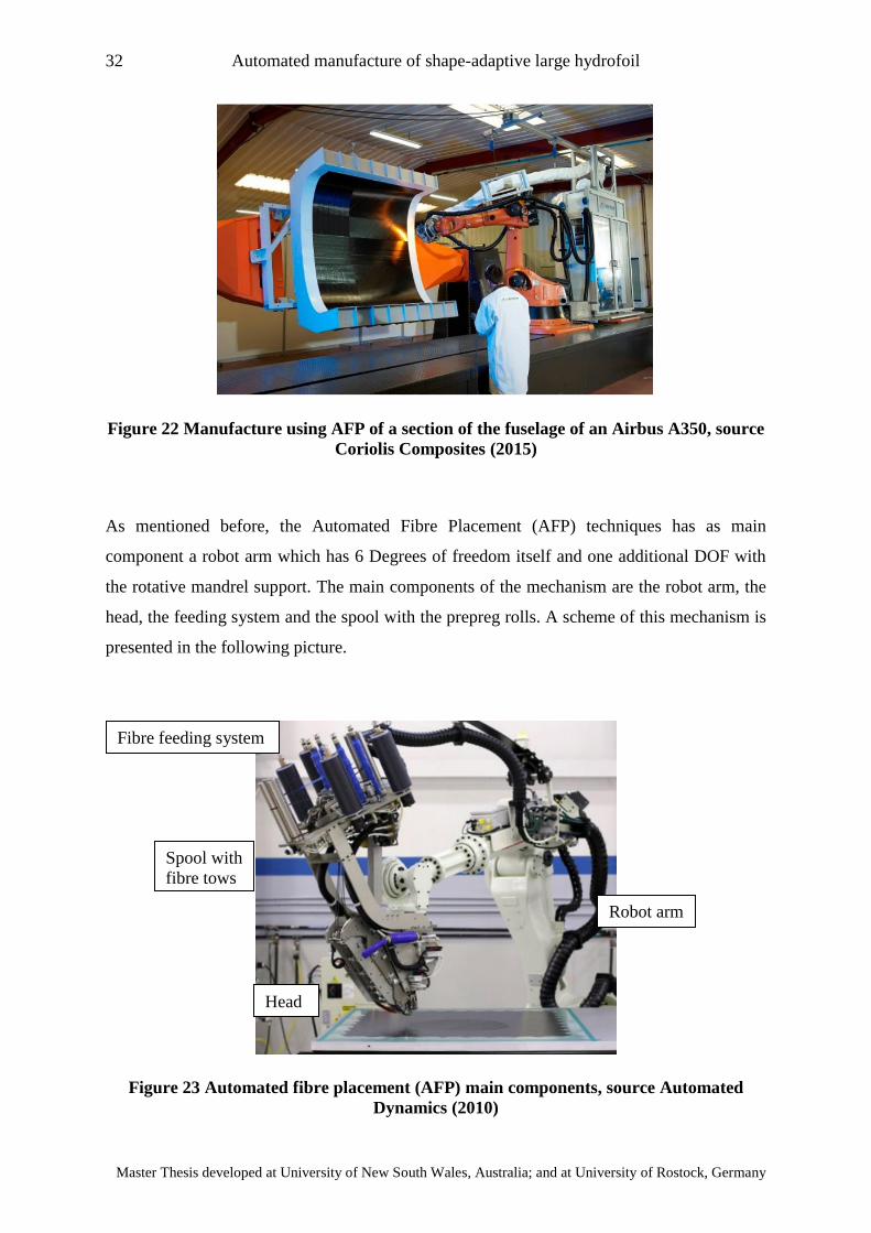
Figure 22 Manufacture using AFP of a section of the fuselage of an Airbus A350, source
Coriolis Composites (2015)
As mentioned before, the Automated Fibre Placement (AFP) techniques has as main
component a robot arm which has 6 Degrees of freedom itself and one additional DOF with
the rotative mandrel support. The main components of the mechanism are the robot arm, the
head, the feeding system and the spool with the prepreg rolls. A scheme of this mechanism is
presented in the following picture.
Figure 23 Automated fibre placement (AFP) main components, source Automated
Dynamics (2010)
Head
Robot arm
Fibre feeding system
Spool with
fibre tows
33 Marco Salvador Sotelo Zorrilla
“EMSHIP” Erasmus Mundus Master Course, period of study September 2017 – February 2019
The machine used in this work is the same as the one presented in the previous figure. This
robot can work with 4 tows at the same time, with a maximum deposition material rate of 0.5
m2 in 3 minutes. All the motions of the robot, feed speed, torch temperature and other
parameters are controlled automatically by the machine.
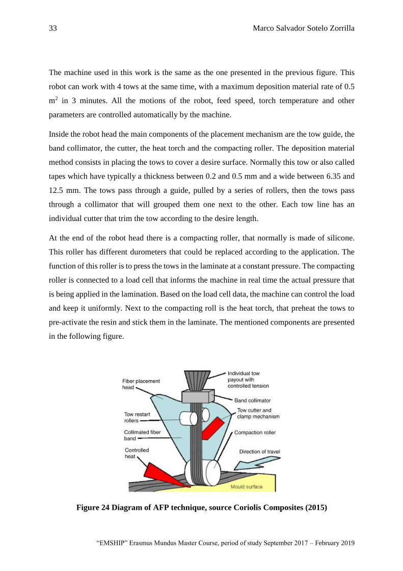
Inside the robot head the main components of the placement mechanism are the tow guide, the
band collimator, the cutter, the heat torch and the compacting roller. The deposition material
method consists in placing the tows to cover a desire surface. Normally this tow or also called
tapes which have typically a thickness between 0.2 and 0.5 mm and a wide between 6.35 and
12.5 mm. The tows pass through a guide, pulled by a series of rollers, then the tows pass
through a collimator that will grouped them one next to the other. Each tow line has an
individual cutter that trim the tow according to the desire length.
At the end of the robot head there is a compacting roller, that normally is made of silicone.
This roller has different durometers that could be replaced according to the application. The
function of this roller is to press the tows in the laminate at a constant pressure. The compacting
roller is connected to a load cell that informs the machine in real time the actual pressure that
is being applied in the lamination. Based on the load cell data, the machine can control the load
and keep it uniformly. Next to the compacting roll is the heat torch, that preheat the tows to
pre-activate the resin and stick them in the laminate. The mentioned components are presented
in the following figure.
Figure 24 Diagram of AFP technique, source Coriolis Composites (2015)
34 Automated manufacture of shape-adaptive large hydrofoil
Master Thesis developed at University of New South Wales, Australia; and at University of Rostock, Germany
For large scale manufacture using this advanced technique is very common to use robot heads
with up to 32 tows, increasing dramatically the productivity, according to Kozaczuk (2016). In
those extreme cases instead of a robot arm, gantry cranes are commonly used. In general AFP
techniques present many potential advantages for high performance composites structures, for
this reason many big airplanes manufacturers like Boing and Airbus are using this
manufacturing method more often.
Main advantages and potential limitations of AFP
The usage of Automated Fibre Placement techniques is increasing due to the high demand of
advance composite structures. Many advantages of this advanced manufacture technique that
can possibly improve in a production line are listed below.
• Precision during lamination. Because the method is completely automated, the
precision that can be achieved in terms of fibre orientation is computerized controlled,
therefore almost no errors in fibre orientation during the deposition material.
• Large scale manufacturing. As mentioned before, big composites manufacturers use
large AFP installed in gantry cranes to build large laminates like wing sections or
fuselage with high quality.
• Higher productivity. According to Kozaczuk (2016), the average time to produce 1m2
of prepreg using manual layup is 1 hour. The typical AFP machine for industrial
applications has 8 tows of 6.35 mm each, having a deposition material rate of 1 m2 per
3 minutes. To increase the productivity big composite manufacturers, use robot heads
with up to 32 tows, reducing the manufacturing time by four.
• Higher quality of laminate. Since the material used in AFP techniques are prepreg
tows, the percentage of voids in the lamination is very low. Also, each tow in placed
continuously along the mould without interruption.

35 Marco Salvador Sotelo Zorrilla
“EMSHIP” Erasmus Mundus Master Course, period of study September 2017 – February 2019
• Curved fibres. With AFP is possible to incorporate curved fibres to modify an specific
mechanical behaviour of the laminate, like the bend/twist capability
• Low material waste. During the manufacture using AFP techniques, the amount of
waste is very low, because the prepregs are stored in rolls and the deposition material
is controlled automatically.
On the other hand, this advance manufacture technique has also some limitations. Some of
them are inherent to the usage of prepregs in general, like the autoclave curing, storage, life
time and high cost of the material. Besides the mentioned before, one of the biggest challenges
by using AFP are the overlapping, gaps, twisting and waving between the tows during the
deposition of the material. According to Croft et al. (2011) gaps and overlaps if they are
isolated, they will not reduce the mechanical properties of the laminate. On the other hand, if
those defects are aligned, it could generate a significant reduction in the global resistance of
the laminate. Other limitation that AFP presents is normally related to the mould geometry.
Since the machine must move the head carrying the prepreg rolls, the mould must be designed
suitable for this purpose. Also, the compacting roller of the AFP machine always needs to be
perpendicular to the mould surface to place properly the tows. For this reason, due to the typical
dimensions of the robot head, this technique is no suitable for small moulds, as mentioned in
White et al. (2017).
3.2. Developing of the Manufacturing tool
The developing of the manufacturing tool consists in the generation of the G-code. As in many
other CNC manufacturing process, the G-code is a file written in a specific format that contains
the different commands that in this case the AFP robot will perform to manufacture the large
hydrofoil. In this section will be explained the procedure considered in the developing of the
G-code.
36 Automated manufacture of shape-adaptive large hydrofoil
Master Thesis developed at University of New South Wales, Australia; and at University of Rostock, Germany
Definition of the geometrical model
The manufacturing strategy that will be used to construct the large hydrofoil is by wrapping
the carbon layers around a fibreglass core, using the AFP technique. By using this manufacture
procedure, it is not necessary to use an open mould to achieve the desired form, reducing
significantly the initial cost. On the other hand, many problems could arise during the
deposition material, especially when the robot is placing the tows in the edges of the hydrofoil.
Also, by using the wrapping technique the finishing surface of the laminate is not expected to
be very nice and smooth.
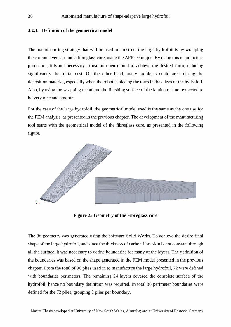
For the case of the large hydrofoil, the geometrical model used is the same as the one use for
the FEM analysis, as presented in the previous chapter. The development of the manufacturing
tool starts with the geometrical model of the fibreglass core, as presented in the following
figure.
The 3d geometry was generated using the software Solid Works. To achieve the desire final
shape of the large hydrofoil, and since the thickness of carbon fibre skin is not constant through
all the surface, it was necessary to define boundaries for many of the layers. The definition of
the boundaries was based on the shape generated in the FEM model presented in the previous
chapter. From the total of 96 plies used in to manufacture the large hydrofoil, 72 were defined
with boundaries perimeters. The remaining 24 layers covered the complete surface of the
hydrofoil; hence no boundary definition was required. In total 36 perimeter boundaries were
defined for the 72 plies, grouping 2 plies per boundary.
Figure 25 Geometry of the Fibreglass core
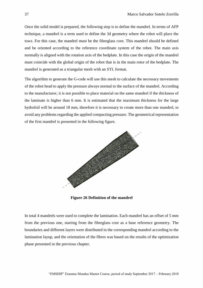
37 Marco Salvador Sotelo Zorrilla
“EMSHIP” Erasmus Mundus Master Course, period of study September 2017 – February 2019
Once the solid model is prepared, the following step is to define the mandrel. In terms of AFP
technique, a mandrel is a term used to define the 3d geometry where the robot will place the
tows. For this case, the mandrel must be the fibreglass core. This mandrel should be defined
and be oriented according to the reference coordinate system of the robot. The main axis
normally is aligned with the rotation axis of the bedplate. In this case the origin of the mandrel
must coincide with the global origin of the robot that is in the main rotor of the bedplate. The
mandrel is generated as a triangular mesh with an STL format.
The algorithm to generate the G-code will use this mesh to calculate the necessary movements
of the robot head to apply the pressure always normal to the surface of the mandrel. According
to the manufacturer, it is not possible to place material on the same mandrel if the thickness of
the laminate is higher than 6 mm. It is estimated that the maximum thickness for the large
hydrofoil will be around 18 mm, therefore it is necessary to create more than one mandrel, to
avoid any problems regarding the applied compacting pressure. The geometrical representation
of the first mandrel is presented in the following figure.
Figure 26 Definition of the mandrel
In total 4 mandrels were used to complete the lamination. Each mandrel has an offset of 5 mm
from the previous one, starting from the fibreglass core as a base reference geometry. The
boundaries and different layers were distributed in the corresponding mandrel according to the
lamination layup, and the orientation of the fibres was based on the results of the optimization
phase presented in the previous chapter.
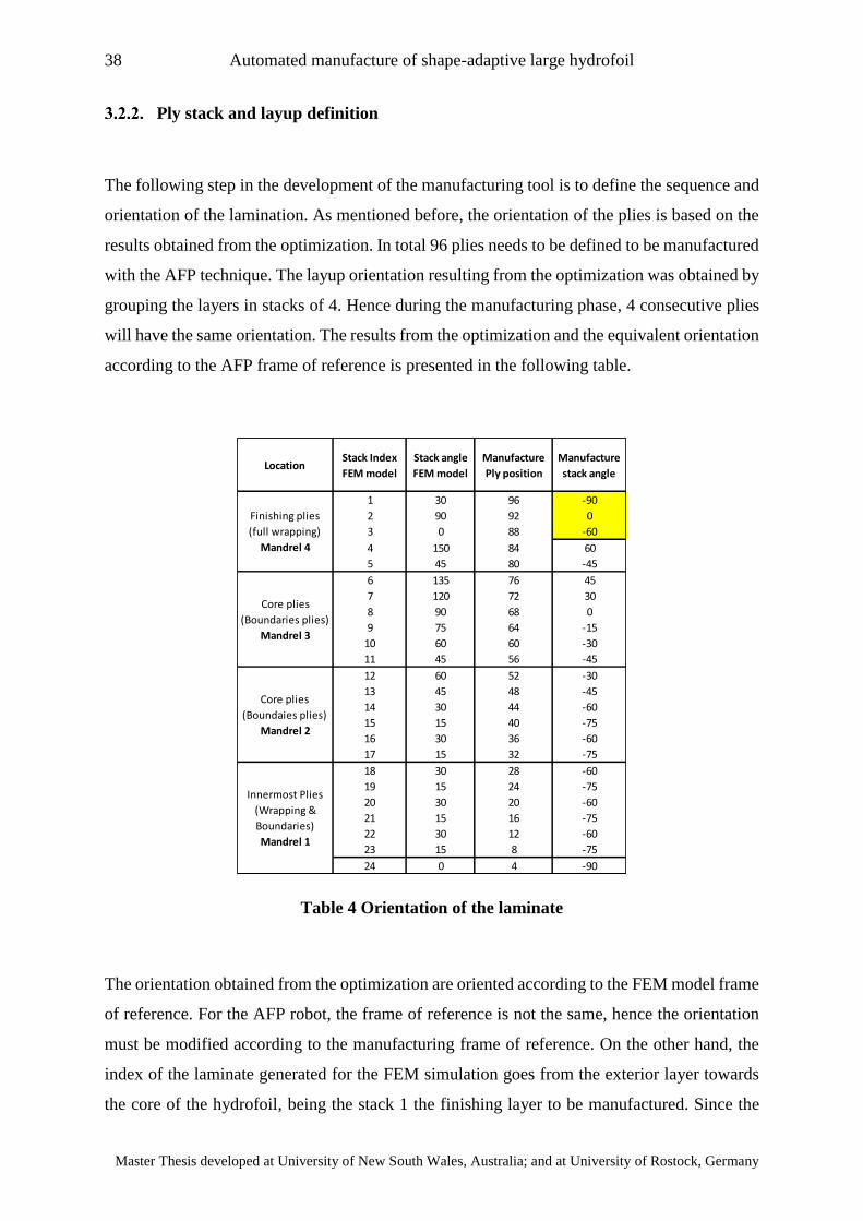
38 Automated manufacture of shape-adaptive large hydrofoil
Master Thesis developed at University of New South Wales, Australia; and at University of Rostock, Germany
Ply stack and layup definition
The following step in the development of the manufacturing tool is to define the sequence and
orientation of the lamination. As mentioned before, the orientation of the plies is based on the
results obtained from the optimization. In total 96 plies needs to be defined to be manufactured
with the AFP technique. The layup orientation resulting from the optimization was obtained by
grouping the layers in stacks of 4. Hence during the manufacturing phase, 4 consecutive plies
will have the same orientation. The results from the optimization and the equivalent orientation
according to the AFP frame of reference is presented in the following table.
Table 4 Orientation of the laminate
The orientation obtained from the optimization are oriented according to the FEM model frame
of reference. For the AFP robot, the frame of reference is not the same, hence the orientation
must be modified according to the manufacturing frame of reference. On the other hand, the
index of the laminate generated for the FEM simulation goes from the exterior layer towards
the core of the hydrofoil, being the stack 1 the finishing layer to be manufactured. Since the
LocationStack Index
FEM model
Stack angle
FEM model
Manufacture
Ply position
Manufacture
stack angle
1 30 96 -90
2 90 92 0
3 0 88 -60
4 150 84 60
5 45 80 -45
6 135 76 45
7 120 72 30
8 90 68 0
9 75 64 -15
10 60 60 -30
11 45 56 -45
12 60 52 -30
13 45 48 -45
14 30 44 -60
15 15 40 -75
16 30 36 -60
17 15 32 -75
18 30 28 -60
19 15 24 -75
20 30 20 -60
21 15 16 -75
22 30 12 -60
23 15 8 -75
24 0 4 -90
Finishing plies
(full wrapping)
Mandrel 4
Core plies
(Boundaries plies)
Mandrel 3
Core plies
(Boundaies plies)
Mandrel 2
Innermost Plies
(Wrapping &
Boundaries)
Mandrel 1
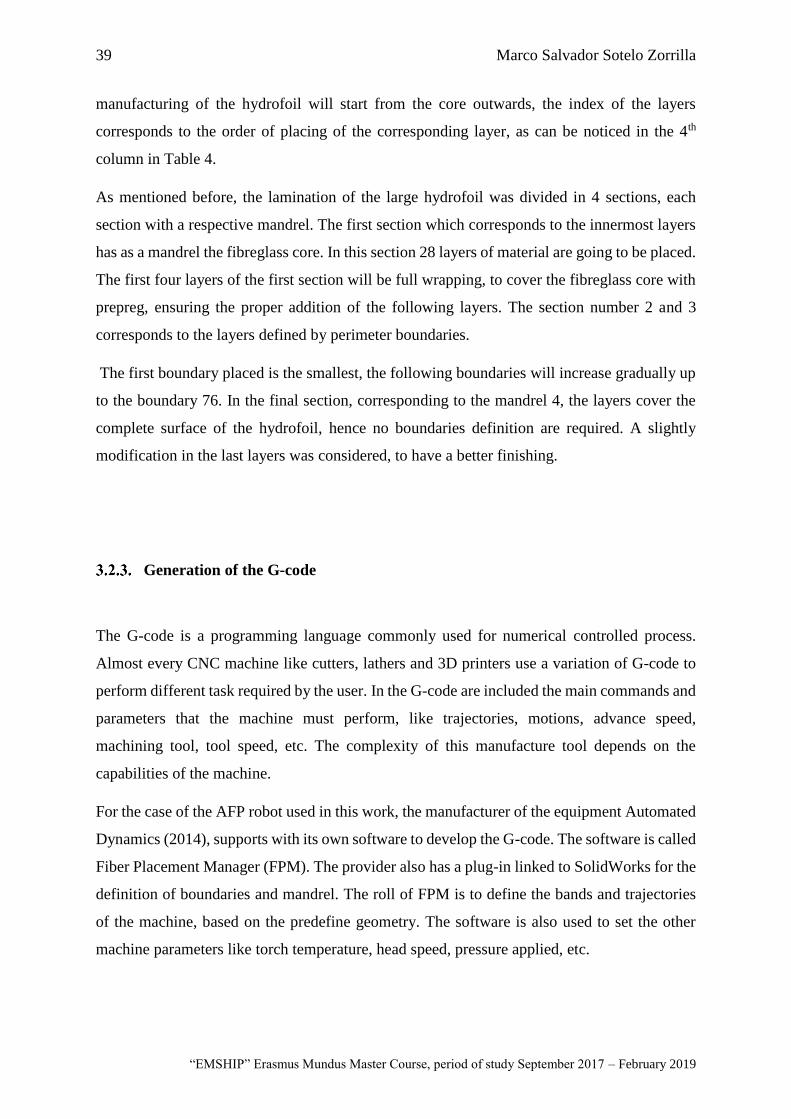
39 Marco Salvador Sotelo Zorrilla
“EMSHIP” Erasmus Mundus Master Course, period of study September 2017 – February 2019
manufacturing of the hydrofoil will start from the core outwards, the index of the layers
corresponds to the order of placing of the corresponding layer, as can be noticed in the 4th
column in Table 4.
As mentioned before, the lamination of the large hydrofoil was divided in 4 sections, each
section with a respective mandrel. The first section which corresponds to the innermost layers
has as a mandrel the fibreglass core. In this section 28 layers of material are going to be placed.
The first four layers of the first section will be full wrapping, to cover the fibreglass core with
prepreg, ensuring the proper addition of the following layers. The section number 2 and 3
corresponds to the layers defined by perimeter boundaries.
The first boundary placed is the smallest, the following boundaries will increase gradually up
to the boundary 76. In the final section, corresponding to the mandrel 4, the layers cover the
complete surface of the hydrofoil, hence no boundaries definition are required. A slightly
modification in the last layers was considered, to have a better finishing.
Generation of the G-code
The G-code is a programming language commonly used for numerical controlled process.
Almost every CNC machine like cutters, lathers and 3D printers use a variation of G-code to
perform different task required by the user. In the G-code are included the main commands and
parameters that the machine must perform, like trajectories, motions, advance speed,
machining tool, tool speed, etc. The complexity of this manufacture tool depends on the
capabilities of the machine.
For the case of the AFP robot used in this work, the manufacturer of the equipment Automated
Dynamics (2014), supports with its own software to develop the G-code. The software is called
Fiber Placement Manager (FPM). The provider also has a plug-in linked to SolidWorks for the
definition of boundaries and mandrel. The roll of FPM is to define the bands and trajectories
of the machine, based on the predefine geometry. The software is also used to set the other
machine parameters like torch temperature, head speed, pressure applied, etc.
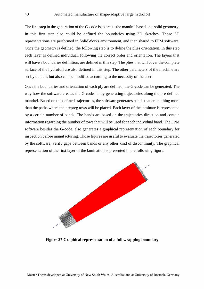
40 Automated manufacture of shape-adaptive large hydrofoil
Master Thesis developed at University of New South Wales, Australia; and at University of Rostock, Germany
The first step in the generation of the G-code is to create the mandrel based on a solid geometry.
In this first step also could be defined the boundaries using 3D sketches. Those 3D
representations are performed in SolidWorks environment, and then shared to FPM software.
Once the geometry is defined, the following step is to define the plies orientation. In this step
each layer is defined individual, following the correct order and orientation. The layers that
will have a boundaries definition, are defined in this step. The plies that will cover the complete
surface of the hydrofoil are also defined in this step. The other parameters of the machine are
set by default, but also can be modified according to the necessity of the user.
Once the boundaries and orientation of each ply are defined, the G-code can be generated. The
way how the software creates the G-codes is by generating trajectories along the pre-defined
mandrel. Based on the defined trajectories, the software generates bands that are nothing more
than the paths where the prepreg tows will be placed. Each layer of the laminate is represented
by a certain number of bands. The bands are based on the trajectories direction and contain
information regarding the number of tows that will be used for each individual band. The FPM
software besides the G-code, also generates a graphical representation of each boundary for
inspection before manufacturing. Those figures are useful to evaluate the trajectories generated
by the software, verify gaps between bands or any other kind of discontinuity. The graphical
representation of the first layer of the lamination is presented in the following figure.
Figure 27 Graphical representation of a full wrapping boundary
41 Marco Salvador Sotelo Zorrilla
“EMSHIP” Erasmus Mundus Master Course, period of study September 2017 – February 2019
In Figure 27 is presented the first boundary of the lamination, which is a full wrapping. It can
be noticed that the layer has a uniform colour, which means that only one band was generated
to complete the task. In this case the trajectory is not so obvious, but it was defined as 90
degrees with respect to the principal axis in colour blue, wrapping completely the fibreglass
core. In the following group of figures are presented the graphical representation of some of
the layers used in the manufacture.
It can be noticed in Figure 28 the presence the different bands represented as the coloured
stripes that cover the surface of each layer. The colour is a representation that the software uses
to distinguish one band to another and easily spot gaps or overlaps between them. The layer at
the right side in the bottom which corresponds to ply 92 was selected as the location to place
the optic fibre sensor, due to the orientation of the fibres. As mentioned before the first layers
defined by boundaries are the smaller, as can be noticed in the upper part of the Figure 28. In
total 96 layers were defined using this procedure. The 96 layers were separated in 4 different
files containing different G-code which corresponds to the 4 different mandrels.
Figure 28 Graphical representation of boundaries and trajectories
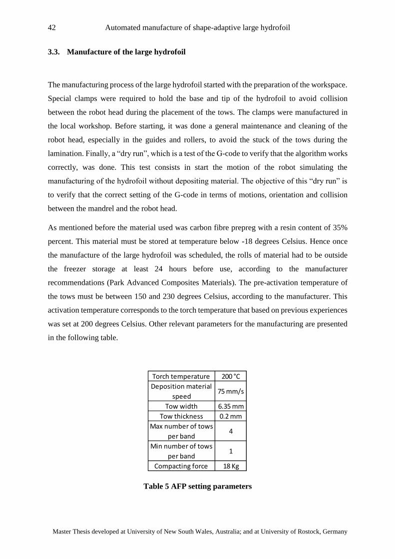
42 Automated manufacture of shape-adaptive large hydrofoil
Master Thesis developed at University of New South Wales, Australia; and at University of Rostock, Germany
3.3. Manufacture of the large hydrofoil
The manufacturing process of the large hydrofoil started with the preparation of the workspace.
Special clamps were required to hold the base and tip of the hydrofoil to avoid collision
between the robot head during the placement of the tows. The clamps were manufactured in
the local workshop. Before starting, it was done a general maintenance and cleaning of the
robot head, especially in the guides and rollers, to avoid the stuck of the tows during the
lamination. Finally, a “dry run”, which is a test of the G-code to verify that the algorithm works
correctly, was done. This test consists in start the motion of the robot simulating the
manufacturing of the hydrofoil without depositing material. The objective of this “dry run” is
to verify that the correct setting of the G-code in terms of motions, orientation and collision
between the mandrel and the robot head.
As mentioned before the material used was carbon fibre prepreg with a resin content of 35%
percent. This material must be stored at temperature below -18 degrees Celsius. Hence once
the manufacture of the large hydrofoil was scheduled, the rolls of material had to be outside
the freezer storage at least 24 hours before use, according to the manufacturer
recommendations (Park Advanced Composites Materials). The pre-activation temperature of
the tows must be between 150 and 230 degrees Celsius, according to the manufacturer. This
activation temperature corresponds to the torch temperature that based on previous experiences
was set at 200 degrees Celsius. Other relevant parameters for the manufacturing are presented
in the following table.
Table 5 AFP setting parameters
Torch temperature 200 °C
Deposition material
speed75 mm/s
Tow width 6.35 mm
Tow thickness 0.2 mm
Max number of tows
per band4
Min number of tows
per band1
Compacting force 18 Kg
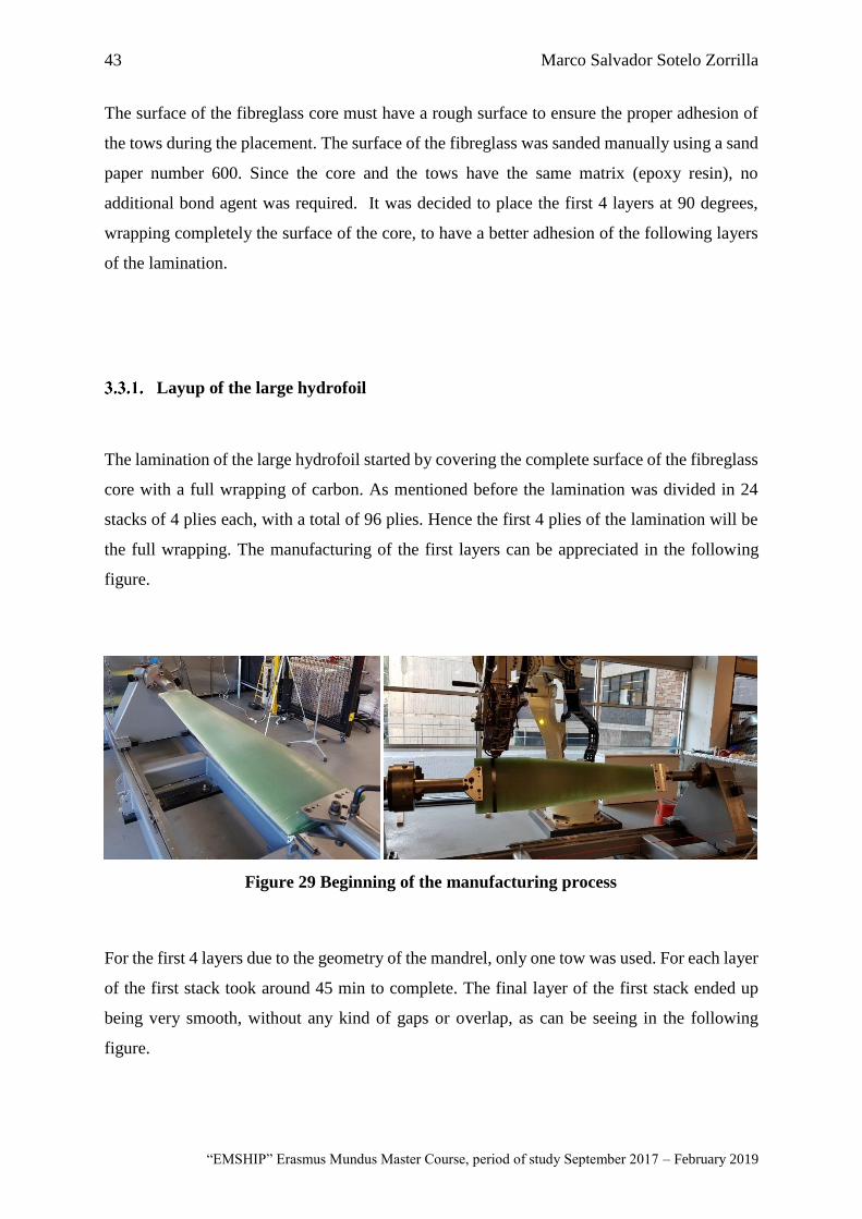
43 Marco Salvador Sotelo Zorrilla
“EMSHIP” Erasmus Mundus Master Course, period of study September 2017 – February 2019
The surface of the fibreglass core must have a rough surface to ensure the proper adhesion of
the tows during the placement. The surface of the fibreglass was sanded manually using a sand
paper number 600. Since the core and the tows have the same matrix (epoxy resin), no
additional bond agent was required. It was decided to place the first 4 layers at 90 degrees,
wrapping completely the surface of the core, to have a better adhesion of the following layers
of the lamination.
Layup of the large hydrofoil
The lamination of the large hydrofoil started by covering the complete surface of the fibreglass
core with a full wrapping of carbon. As mentioned before the lamination was divided in 24
stacks of 4 plies each, with a total of 96 plies. Hence the first 4 plies of the lamination will be
the full wrapping. The manufacturing of the first layers can be appreciated in the following
figure.
For the first 4 layers due to the geometry of the mandrel, only one tow was used. For each layer
of the first stack took around 45 min to complete. The final layer of the first stack ended up
being very smooth, without any kind of gaps or overlap, as can be seeing in the following
figure.
Figure 29 Beginning of the manufacturing process
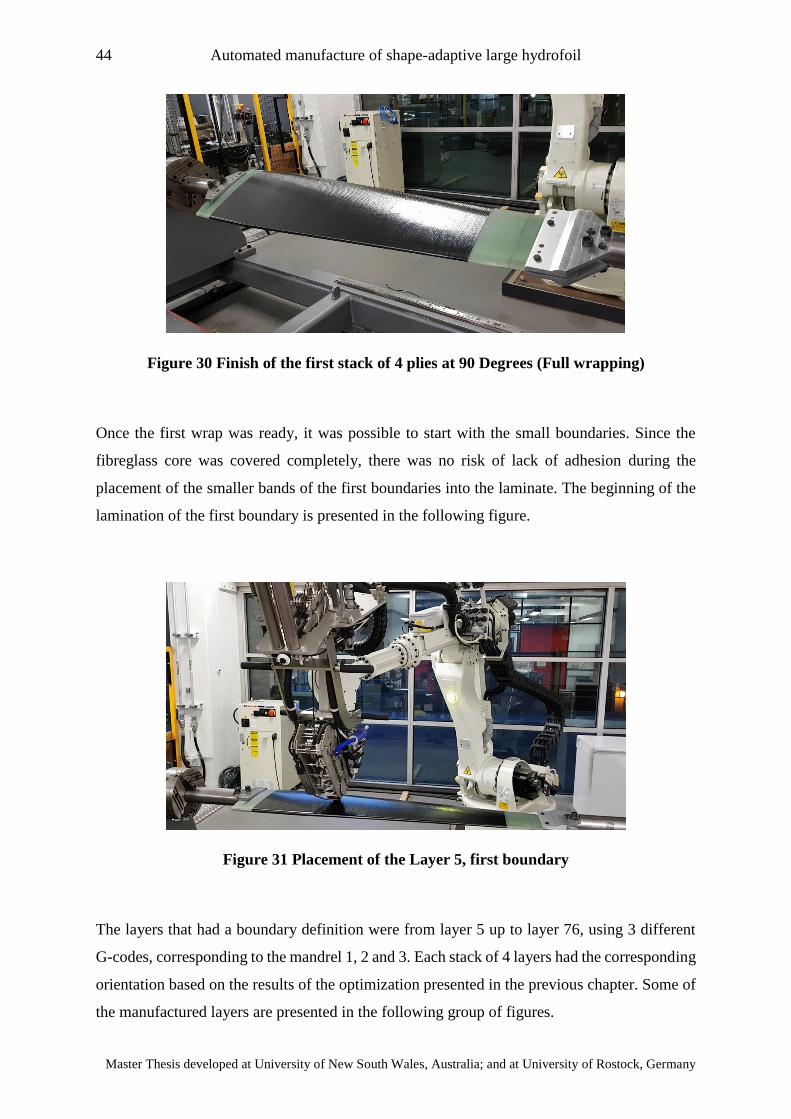
44 Automated manufacture of shape-adaptive large hydrofoil
Master Thesis developed at University of New South Wales, Australia; and at University of Rostock, Germany
Figure 30 Finish of the first stack of 4 plies at 90 Degrees (Full wrapping)
Once the first wrap was ready, it was possible to start with the small boundaries. Since the
fibreglass core was covered completely, there was no risk of lack of adhesion during the
placement of the smaller bands of the first boundaries into the laminate. The beginning of the
lamination of the first boundary is presented in the following figure.
Figure 31 Placement of the Layer 5, first boundary
The layers that had a boundary definition were from layer 5 up to layer 76, using 3 different
G-codes, corresponding to the mandrel 1, 2 and 3. Each stack of 4 layers had the corresponding
orientation based on the results of the optimization presented in the previous chapter. Some of
the manufactured layers are presented in the following group of figures.
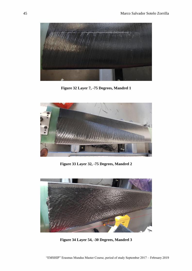
45 Marco Salvador Sotelo Zorrilla
“EMSHIP” Erasmus Mundus Master Course, period of study September 2017 – February 2019
Figure 32 Layer 7, -75 Degrees, Mandrel 1
Figure 33 Layer 32, -75 Degrees, Mandrel 2
Figure 34 Layer 54, -30 Degrees, Mandrel 3
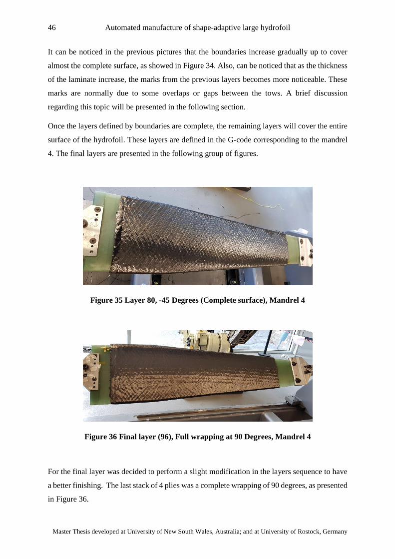
46 Automated manufacture of shape-adaptive large hydrofoil
Master Thesis developed at University of New South Wales, Australia; and at University of Rostock, Germany
It can be noticed in the previous pictures that the boundaries increase gradually up to cover
almost the complete surface, as showed in Figure 34. Also, can be noticed that as the thickness
of the laminate increase, the marks from the previous layers becomes more noticeable. These
marks are normally due to some overlaps or gaps between the tows. A brief discussion
regarding this topic will be presented in the following section.
Once the layers defined by boundaries are complete, the remaining layers will cover the entire
surface of the hydrofoil. These layers are defined in the G-code corresponding to the mandrel
4. The final layers are presented in the following group of figures.
Figure 35 Layer 80, -45 Degrees (Complete surface), Mandrel 4
Figure 36 Final layer (96), Full wrapping at 90 Degrees, Mandrel 4
For the final layer was decided to perform a slight modification in the layers sequence to have
a better finishing. The last stack of 4 plies was a complete wrapping of 90 degrees, as presented
in Figure 36.
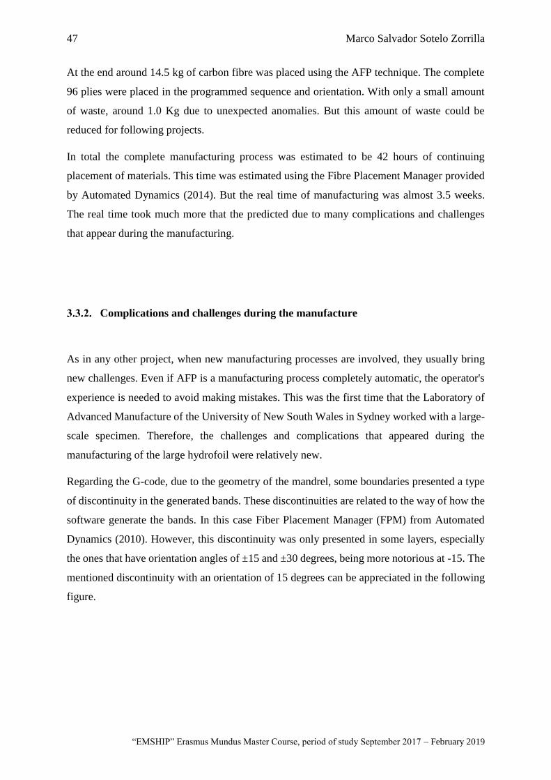
47 Marco Salvador Sotelo Zorrilla
“EMSHIP” Erasmus Mundus Master Course, period of study September 2017 – February 2019
At the end around 14.5 kg of carbon fibre was placed using the AFP technique. The complete
96 plies were placed in the programmed sequence and orientation. With only a small amount
of waste, around 1.0 Kg due to unexpected anomalies. But this amount of waste could be
reduced for following projects.
In total the complete manufacturing process was estimated to be 42 hours of continuing
placement of materials. This time was estimated using the Fibre Placement Manager provided
by Automated Dynamics (2014). But the real time of manufacturing was almost 3.5 weeks.
The real time took much more that the predicted due to many complications and challenges
that appear during the manufacturing.
Complications and challenges during the manufacture
As in any other project, when new manufacturing processes are involved, they usually bring
new challenges. Even if AFP is a manufacturing process completely automatic, the operator's
experience is needed to avoid making mistakes. This was the first time that the Laboratory of
Advanced Manufacture of the University of New South Wales in Sydney worked with a large-
scale specimen. Therefore, the challenges and complications that appeared during the
manufacturing of the large hydrofoil were relatively new.
Regarding the G-code, due to the geometry of the mandrel, some boundaries presented a type
of discontinuity in the generated bands. These discontinuities are related to the way of how the
software generate the bands. In this case Fiber Placement Manager (FPM) from Automated
Dynamics (2010). However, this discontinuity was only presented in some layers, especially
the ones that have orientation angles of ±15 and ±30 degrees, being more notorious at -15. The
mentioned discontinuity with an orientation of 15 degrees can be appreciated in the following
figure.
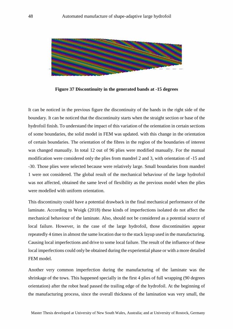
48 Automated manufacture of shape-adaptive large hydrofoil
Master Thesis developed at University of New South Wales, Australia; and at University of Rostock, Germany
Figure 37 Discontinuity in the generated bands at -15 degrees
It can be noticed in the previous figure the discontinuity of the bands in the right side of the
boundary. It can be noticed that the discontinuity starts when the straight section or base of the
hydrofoil finish. To understand the impact of this variation of the orientation in certain sections
of some boundaries, the solid model in FEM was updated. with this change in the orientation
of certain boundaries. The orientation of the fibres in the region of the boundaries of interest
was changed manually. In total 12 out of 96 plies were modified manually. For the manual
modification were considered only the plies from mandrel 2 and 3, with orientation of -15 and
-30. Those plies were selected because were relatively large. Small boundaries from mandrel
1 were not considered. The global result of the mechanical behaviour of the large hydrofoil
was not affected, obtained the same level of flexibility as the previous model when the plies
were modelled with uniform orientation.
This discontinuity could have a potential drawback in the final mechanical performance of the
laminate. According to Woigk (2018) these kinds of imperfections isolated do not affect the
mechanical behaviour of the laminate. Also, should not be considered as a potential source of
local failure. However, in the case of the large hydrofoil, those discontinuities appear
repeatedly 4 times in almost the same location due to the stack layup used in the manufacturing.
Causing local imperfections and drive to some local failure. The result of the influence of these
local imperfections could only be obtained during the experiential phase or with a more detailed
FEM model.
Another very common imperfection during the manufacturing of the laminate was the
shrinkage of the tows. This happened specially in the first 4 plies of full wrapping (90 degrees
orientation) after the robot head passed the trailing edge of the hydrofoil. At the beginning of
the manufacturing process, since the overall thickness of the lamination was very small, the
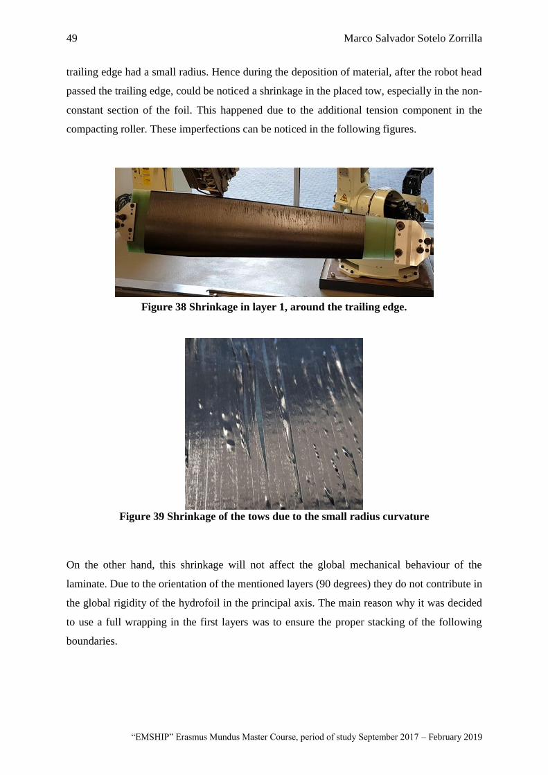
49 Marco Salvador Sotelo Zorrilla
“EMSHIP” Erasmus Mundus Master Course, period of study September 2017 – February 2019
trailing edge had a small radius. Hence during the deposition of material, after the robot head
passed the trailing edge, could be noticed a shrinkage in the placed tow, especially in the non-
constant section of the foil. This happened due to the additional tension component in the
compacting roller. These imperfections can be noticed in the following figures.
Figure 39 Shrinkage of the tows due to the small radius curvature
On the other hand, this shrinkage will not affect the global mechanical behaviour of the
laminate. Due to the orientation of the mentioned layers (90 degrees) they do not contribute in
the global rigidity of the hydrofoil in the principal axis. The main reason why it was decided
to use a full wrapping in the first layers was to ensure the proper stacking of the following
boundaries.
Figure 38 Shrinkage in layer 1, around the trailing edge.
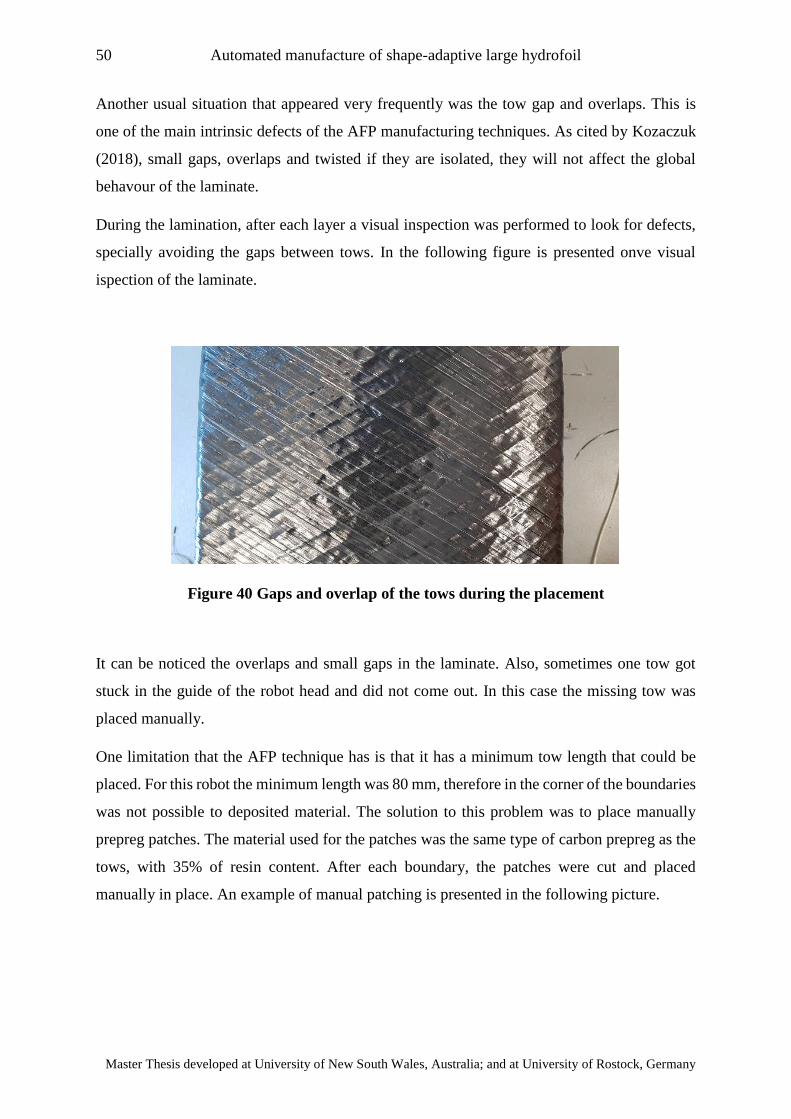
50 Automated manufacture of shape-adaptive large hydrofoil
Master Thesis developed at University of New South Wales, Australia; and at University of Rostock, Germany
Another usual situation that appeared very frequently was the tow gap and overlaps. This is
one of the main intrinsic defects of the AFP manufacturing techniques. As cited by Kozaczuk
(2018), small gaps, overlaps and twisted if they are isolated, they will not affect the global
behavour of the laminate.
During the lamination, after each layer a visual inspection was performed to look for defects,
specially avoiding the gaps between tows. In the following figure is presented onve visual
ispection of the laminate.
Figure 40 Gaps and overlap of the tows during the placement
It can be noticed the overlaps and small gaps in the laminate. Also, sometimes one tow got
stuck in the guide of the robot head and did not come out. In this case the missing tow was
placed manually.
One limitation that the AFP technique has is that it has a minimum tow length that could be
placed. For this robot the minimum length was 80 mm, therefore in the corner of the boundaries
was not possible to deposited material. The solution to this problem was to place manually
prepreg patches. The material used for the patches was the same type of carbon prepreg as the
tows, with 35% of resin content. After each boundary, the patches were cut and placed
manually in place. An example of manual patching is presented in the following picture.
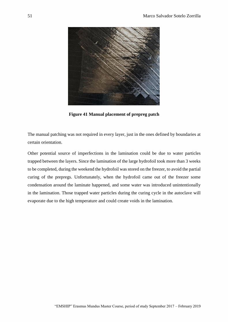
51 Marco Salvador Sotelo Zorrilla
“EMSHIP” Erasmus Mundus Master Course, period of study September 2017 – February 2019
Figure 41 Manual placement of prepreg patch
The manual patching was not required in every layer, just in the ones defined by boundaries at
certain orientation.
Other potential source of imperfections in the lamination could be due to water particles
trapped between the layers. Since the lamination of the large hydrofoil took more than 3 weeks
to be completed, during the weekend the hydrofoil was stored on the freezer, to avoid the partial
curing of the prepregs. Unfortunately, when the hydrofoil came out of the freezer some
condensation around the laminate happened, and some water was introduced unintentionally
in the lamination. Those trapped water particles during the curing cycle in the autoclave will
evaporate due to the high temperature and could create voids in the lamination.

52 Automated manufacture of shape-adaptive large hydrofoil
Master Thesis developed at University of New South Wales, Australia; and at University of Rostock, Germany
This page is intentionally left blank

53 Marco Salvador Sotelo Zorrilla
“EMSHIP” Erasmus Mundus Master Course, period of study September 2017 – February 2019
CHAPTER 4
Thick laminate curing
4.1. Introduction to autoclave curing for advanced composites
According to Campbell (2003), autoclaves have been widely used in the manufacturing of high-
quality laminates. Due to the versatility of this equipment, it is possible to cure almost any
shape because the pressure and temperature is uniform inside the pressure vessel. The autoclave
consists in a pressure vessel, a control system, an electrical system, a gas generation system
and a vacuum system. The main disadvantage of using this equipment is the initial investment.
The size of the part that can be cured in the autoclave depends on the space that this equipment
can accommodate. Some big airplane manufacturers like Boeing or Airbus use large autoclave,
able to accommodate the complete laminate of a fuselage or wings. When working with large
autoclaves, it is very common to use racks to accommodate several parts and cure them as a
batch.
Normally autoclaves are pressurized with inert gas like nitrogen or carbon dioxide. This gas is
circulated by a big fan in the rear section of the pressure vessel, passing through the walls that
normally have some heater systems. It is very common to use electrical heaters but is some
cases steam is used, especially in older autoclaves. The heated gas strikes the front door of the
vessel and flows back down the centre of the autoclave, heating the laminate inside. The
representation of a typical autoclave is presented in the following figure.
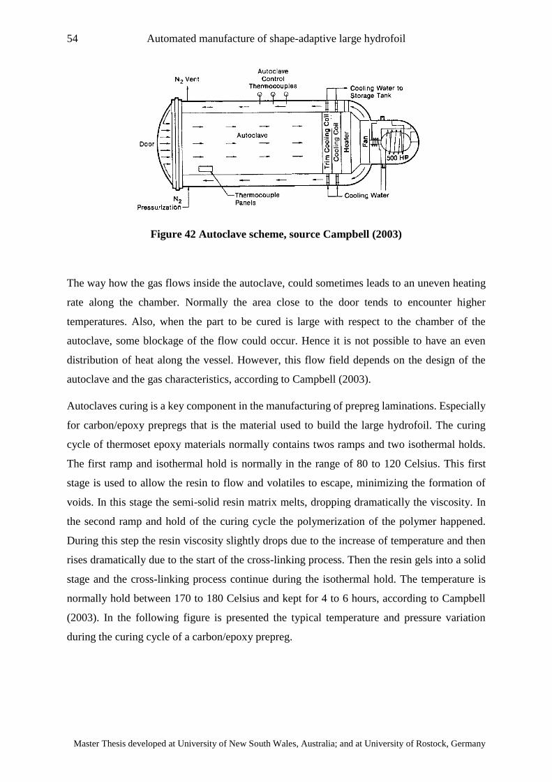
54 Automated manufacture of shape-adaptive large hydrofoil
Master Thesis developed at University of New South Wales, Australia; and at University of Rostock, Germany
Figure 42 Autoclave scheme, source Campbell (2003)
The way how the gas flows inside the autoclave, could sometimes leads to an uneven heating
rate along the chamber. Normally the area close to the door tends to encounter higher
temperatures. Also, when the part to be cured is large with respect to the chamber of the
autoclave, some blockage of the flow could occur. Hence it is not possible to have an even
distribution of heat along the vessel. However, this flow field depends on the design of the
autoclave and the gas characteristics, according to Campbell (2003).
Autoclaves curing is a key component in the manufacturing of prepreg laminations. Especially
for carbon/epoxy prepregs that is the material used to build the large hydrofoil. The curing
cycle of thermoset epoxy materials normally contains twos ramps and two isothermal holds.
The first ramp and isothermal hold is normally in the range of 80 to 120 Celsius. This first
stage is used to allow the resin to flow and volatiles to escape, minimizing the formation of
voids. In this stage the semi-solid resin matrix melts, dropping dramatically the viscosity. In
the second ramp and hold of the curing cycle the polymerization of the polymer happened.
During this step the resin viscosity slightly drops due to the increase of temperature and then
rises dramatically due to the start of the cross-linking process. Then the resin gels into a solid
stage and the cross-linking process continue during the isothermal hold. The temperature is
normally hold between 170 to 180 Celsius and kept for 4 to 6 hours, according to Campbell
(2003). In the following figure is presented the typical temperature and pressure variation
during the curing cycle of a carbon/epoxy prepreg.
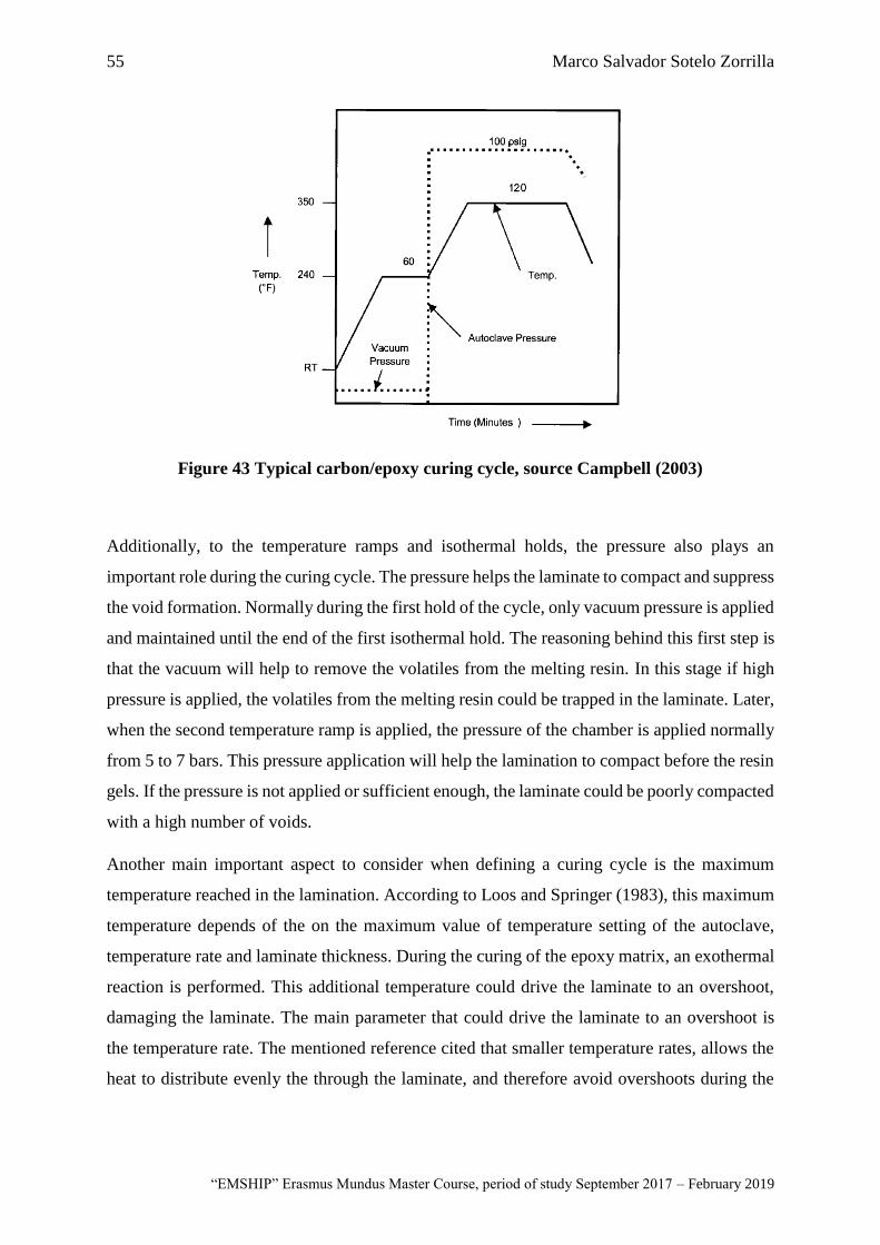
55 Marco Salvador Sotelo Zorrilla
“EMSHIP” Erasmus Mundus Master Course, period of study September 2017 – February 2019
Figure 43 Typical carbon/epoxy curing cycle, source Campbell (2003)
Additionally, to the temperature ramps and isothermal holds, the pressure also plays an
important role during the curing cycle. The pressure helps the laminate to compact and suppress
the void formation. Normally during the first hold of the cycle, only vacuum pressure is applied
and maintained until the end of the first isothermal hold. The reasoning behind this first step is
that the vacuum will help to remove the volatiles from the melting resin. In this stage if high
pressure is applied, the volatiles from the melting resin could be trapped in the laminate. Later,
when the second temperature ramp is applied, the pressure of the chamber is applied normally
from 5 to 7 bars. This pressure application will help the lamination to compact before the resin
gels. If the pressure is not applied or sufficient enough, the laminate could be poorly compacted
with a high number of voids.
Another main important aspect to consider when defining a curing cycle is the maximum
temperature reached in the lamination. According to Loos and Springer (1983), this maximum
temperature depends of the on the maximum value of temperature setting of the autoclave,
temperature rate and laminate thickness. During the curing of the epoxy matrix, an exothermal
reaction is performed. This additional temperature could drive the laminate to an overshoot,
damaging the laminate. The main parameter that could drive the laminate to an overshoot is
the temperature rate. The mentioned reference cited that smaller temperature rates, allows the
heat to distribute evenly the through the laminate, and therefore avoid overshoots during the
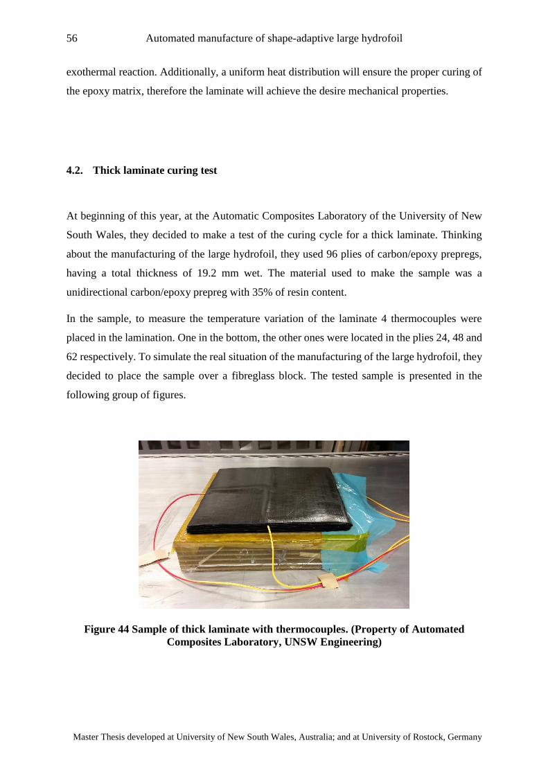
56 Automated manufacture of shape-adaptive large hydrofoil
Master Thesis developed at University of New South Wales, Australia; and at University of Rostock, Germany
exothermal reaction. Additionally, a uniform heat distribution will ensure the proper curing of
the epoxy matrix, therefore the laminate will achieve the desire mechanical properties.
4.2. Thick laminate curing test
At beginning of this year, at the Automatic Composites Laboratory of the University of New
South Wales, they decided to make a test of the curing cycle for a thick laminate. Thinking
about the manufacturing of the large hydrofoil, they used 96 plies of carbon/epoxy prepregs,
having a total thickness of 19.2 mm wet. The material used to make the sample was a
unidirectional carbon/epoxy prepreg with 35% of resin content.
In the sample, to measure the temperature variation of the laminate 4 thermocouples were
placed in the lamination. One in the bottom, the other ones were located in the plies 24, 48 and
62 respectively. To simulate the real situation of the manufacturing of the large hydrofoil, they
decided to place the sample over a fibreglass block. The tested sample is presented in the
following group of figures.
Figure 44 Sample of thick laminate with thermocouples. (Property of Automated
Composites Laboratory, UNSW Engineering)
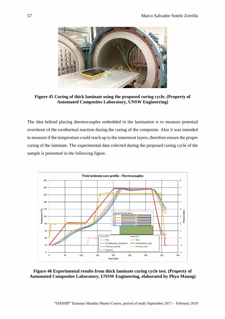
57 Marco Salvador Sotelo Zorrilla
“EMSHIP” Erasmus Mundus Master Course, period of study September 2017 – February 2019
Figure 45 Curing of thick laminate using the proposed curing cycle. (Property of
Automated Composites Laboratory, UNSW Engineering)
The idea behind placing thermocouples embedded in the lamination is to measure potential
overshoot of the exothermal reaction during the curing of the composite. Also it was intended
to measure if the temperature could reach up to the innermost layers, therefore ensure the proper
curing of the laminate. The experimental data colected during the proposed curing cycle of the
sample is presented in the following figure.
Figure 46 Experimental results from thick laminate curing cycle test. (Property of
Automated Composites Laboratory, UNSW Engineering, elaborated by Phyo Maung)
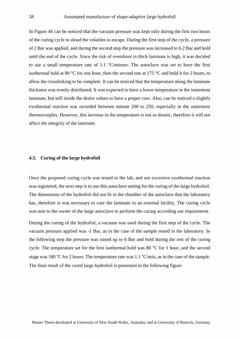
58 Automated manufacture of shape-adaptive large hydrofoil
Master Thesis developed at University of New South Wales, Australia; and at University of Rostock, Germany
In Figure 46 can be noticed that the vacuum pressure was kept only during the first two hours
of the curing cycle to aloud the volatiles to escape. During the first step of the cycle, a pressure
of 2 Bar was applied, and during the second step the pressure was increased to 6.2 Bar and hold
until the end of the cycle. Since the risk of overshoot in thick laminate is high, it was decided
to use a small temperature rate of 1.1 °C/minute. The autoclave was set to have the first
isothermal hold at 80 °C for one hour, then the second one at 175 °C and hold it for 2 hours, to
allow the crosslinking to be complete. It can be noticed that the temperature along the laminate
thickness was evenly distributed. It was expected to have a lower temperature in the innermost
laminate, but still inside the desire values to have a proper cure. Also, can be noticed a slightly
exothermal reaction was recorded between minute 200 to 250, especially in the outermost
thermocouples. However, this increase in the temperature is not so drastic, therefore it will not
affect the integrity of the laminate.
4.3. Curing of the large hydrofoil
Once the proposed curing cycle was tested in the lab, and not excessive exothermal reaction
was registered, the next step is to use this autoclave setting for the curing of the large hydrofoil.
The dimensions of the hydrofoil did not fit in the chamber of the autoclave that the laboratory
has, therefore is was necessary to cure the laminate in an external facility. The curing cycle
was sent to the owner of the large autoclave to perform the curing according our requirement.
During the curing of the hydrofoil, a vacuum was used during the first step of the cycle. The
vacuum pressure applied was -1 Bar, as in the case of the sample tested in the laboratory. In
the following step the pressure was raised up to 6 Bar and hold during the rest of the curing
cycle. The temperature set for the first isothermal hold was 80 °C for 1 hour, and the second
stage was 180 °C for 2 hours. The temperature rate was 1.1 °C/min, as in the case of the sample.
The final result of the cured large hydrofoil is presented in the following figure.
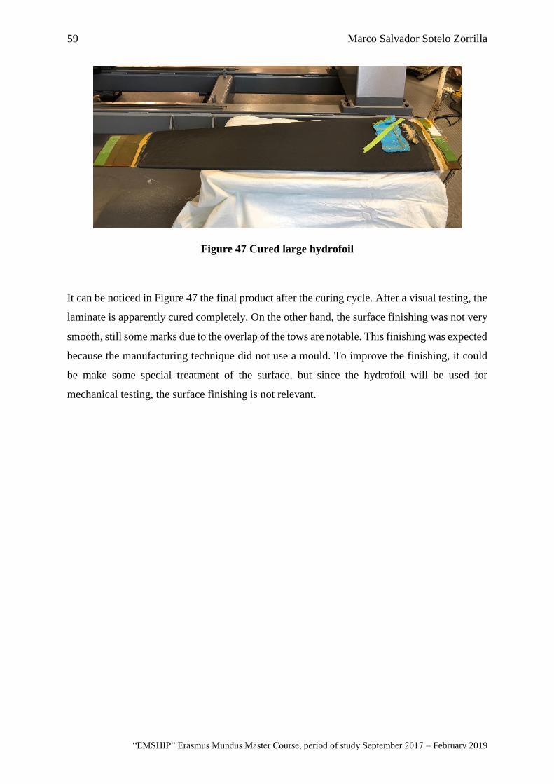
59 Marco Salvador Sotelo Zorrilla
“EMSHIP” Erasmus Mundus Master Course, period of study September 2017 – February 2019
Figure 47 Cured large hydrofoil
It can be noticed in Figure 47 the final product after the curing cycle. After a visual testing, the
laminate is apparently cured completely. On the other hand, the surface finishing was not very
smooth, still some marks due to the overlap of the tows are notable. This finishing was expected
because the manufacturing technique did not use a mould. To improve the finishing, it could
be make some special treatment of the surface, but since the hydrofoil will be used for
mechanical testing, the surface finishing is not relevant.

60 Automated manufacture of shape-adaptive large hydrofoil
Master Thesis developed at University of New South Wales, Australia; and at University of Rostock, Germany
This page is intentionally left blank
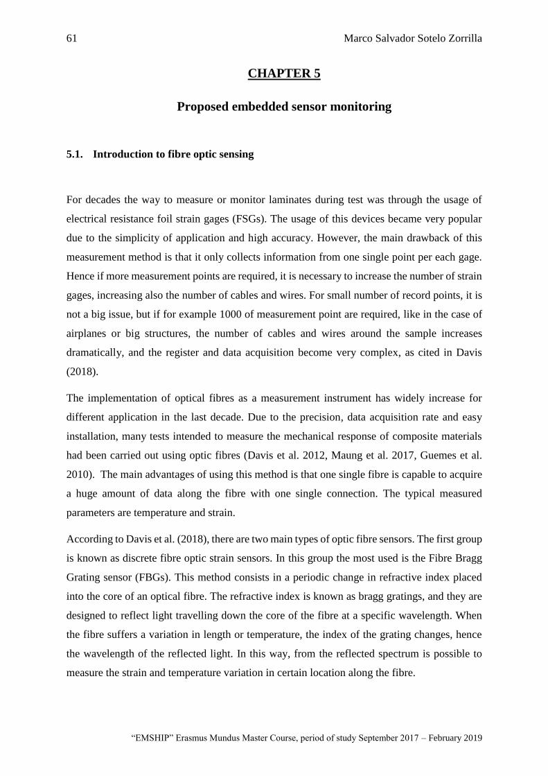
61 Marco Salvador Sotelo Zorrilla
“EMSHIP” Erasmus Mundus Master Course, period of study September 2017 – February 2019
CHAPTER 5
Proposed embedded sensor monitoring
5.1. Introduction to fibre optic sensing
For decades the way to measure or monitor laminates during test was through the usage of
electrical resistance foil strain gages (FSGs). The usage of this devices became very popular
due to the simplicity of application and high accuracy. However, the main drawback of this
measurement method is that it only collects information from one single point per each gage.
Hence if more measurement points are required, it is necessary to increase the number of strain
gages, increasing also the number of cables and wires. For small number of record points, it is
not a big issue, but if for example 1000 of measurement point are required, like in the case of
airplanes or big structures, the number of cables and wires around the sample increases
dramatically, and the register and data acquisition become very complex, as cited in Davis
(2018).
The implementation of optical fibres as a measurement instrument has widely increase for
different application in the last decade. Due to the precision, data acquisition rate and easy
installation, many tests intended to measure the mechanical response of composite materials
had been carried out using optic fibres (Davis et al. 2012, Maung et al. 2017, Guemes et al.
2010). The main advantages of using this method is that one single fibre is capable to acquire
a huge amount of data along the fibre with one single connection. The typical measured
parameters are temperature and strain.
According to Davis et al. (2018), there are two main types of optic fibre sensors. The first group
is known as discrete fibre optic strain sensors. In this group the most used is the Fibre Bragg
Grating sensor (FBGs). This method consists in a periodic change in refractive index placed
into the core of an optical fibre. The refractive index is known as bragg gratings, and they are
designed to reflect light travelling down the core of the fibre at a specific wavelength. When
the fibre suffers a variation in length or temperature, the index of the grating changes, hence
the wavelength of the reflected light. In this way, from the reflected spectrum is possible to
measure the strain and temperature variation in certain location along the fibre.
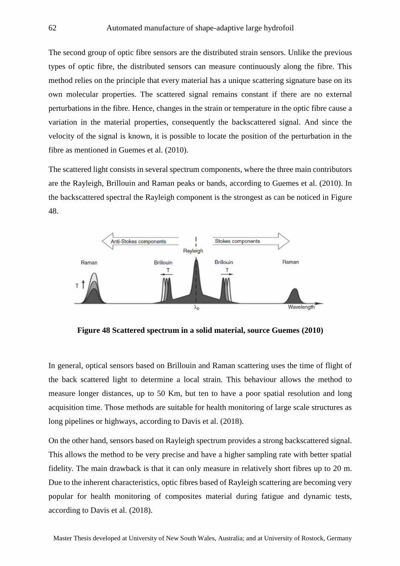
62 Automated manufacture of shape-adaptive large hydrofoil
Master Thesis developed at University of New South Wales, Australia; and at University of Rostock, Germany
The second group of optic fibre sensors are the distributed strain sensors. Unlike the previous
types of optic fibre, the distributed sensors can measure continuously along the fibre. This
method relies on the principle that every material has a unique scattering signature base on its
own molecular properties. The scattered signal remains constant if there are no external
perturbations in the fibre. Hence, changes in the strain or temperature in the optic fibre cause a
variation in the material properties, consequently the backscattered signal. And since the
velocity of the signal is known, it is possible to locate the position of the perturbation in the
fibre as mentioned in Guemes et al. (2010).
The scattered light consists in several spectrum components, where the three main contributors
are the Rayleigh, Brillouin and Raman peaks or bands, according to Guemes et al. (2010). In
the backscattered spectral the Rayleigh component is the strongest as can be noticed in Figure
48.
Figure 48 Scattered spectrum in a solid material, source Guemes (2010)
In general, optical sensors based on Brillouin and Raman scattering uses the time of flight of
the back scattered light to determine a local strain. This behaviour allows the method to
measure longer distances, up to 50 Km, but ten to have a poor spatial resolution and long
acquisition time. Those methods are suitable for health monitoring of large scale structures as
long pipelines or highways, according to Davis et al. (2018).
On the other hand, sensors based on Rayleigh spectrum provides a strong backscattered signal.
This allows the method to be very precise and have a higher sampling rate with better spatial
fidelity. The main drawback is that it can only measure in relatively short fibres up to 20 m.
Due to the inherent characteristics, optic fibres based of Rayleigh scattering are becoming very
popular for health monitoring of composites material during fatigue and dynamic tests,
according to Davis et al. (2018).
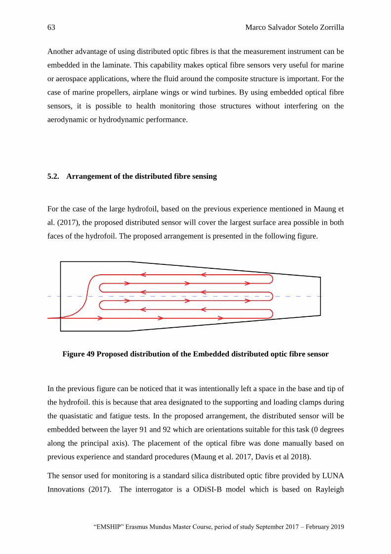
63 Marco Salvador Sotelo Zorrilla
“EMSHIP” Erasmus Mundus Master Course, period of study September 2017 – February 2019
Another advantage of using distributed optic fibres is that the measurement instrument can be
embedded in the laminate. This capability makes optical fibre sensors very useful for marine
or aerospace applications, where the fluid around the composite structure is important. For the
case of marine propellers, airplane wings or wind turbines. By using embedded optical fibre
sensors, it is possible to health monitoring those structures without interfering on the
aerodynamic or hydrodynamic performance.
5.2. Arrangement of the distributed fibre sensing
For the case of the large hydrofoil, based on the previous experience mentioned in Maung et
al. (2017), the proposed distributed sensor will cover the largest surface area possible in both
faces of the hydrofoil. The proposed arrangement is presented in the following figure.
Figure 49 Proposed distribution of the Embedded distributed optic fibre sensor
In the previous figure can be noticed that it was intentionally left a space in the base and tip of
the hydrofoil. this is because that area designated to the supporting and loading clamps during
the quasistatic and fatigue tests. In the proposed arrangement, the distributed sensor will be
embedded between the layer 91 and 92 which are orientations suitable for this task (0 degrees
along the principal axis). The placement of the optical fibre was done manually based on
previous experience and standard procedures (Maung et al. 2017, Davis et al 2018).
The sensor used for monitoring is a standard silica distributed optic fibre provided by LUNA
Innovations (2017). The interrogator is a ODiSI-B model which is based on Rayleigh
64 Automated manufacture of shape-adaptive large hydrofoil
Master Thesis developed at University of New South Wales, Australia; and at University of Rostock, Germany
backscattering signals. This equipment is capable to record data of strain and temperature along
the fibre. It is also possible to have a sample rate of 250 Hz in a sensing length up to 20 m of
continuous fibre.
5.3. Placement of the distributed fibre sensing
The placement of the optical sensor starts with the mark of the path where the fibre must follow.
In this step the proposed path has a total length of 6.5 m of optical fibre, with a usable
measurement length of 5.7 m. It is considerable as usable measurement length to the straight
part of the optical fibre, aligned with the principal axis.
Before placing the sensor, it is necessary to protect the fibre with a plastic and a metallic tube
in the start and end of the sensor. The optical fibre pass through a thin plastic tube. This
procedure is repeated in the end of the fibre. Later both plastic tubes pass through a metallic
tube, and the space between them is filled with high temperature resistant silicone. The metallic
tube is used as a protective sleeve that will be in the root of the foil. To avoid an excess of
material in the root area, it was necessary to make a grove (remove some material), to allocate
the small tube.
To place the optical fibre in the correct position, temporary tapes were used to hold the fibre.
Then to fix the fibre to the laminate it was used an epoxy glue. The placement of the fibre can
be appreciated in the following figure.
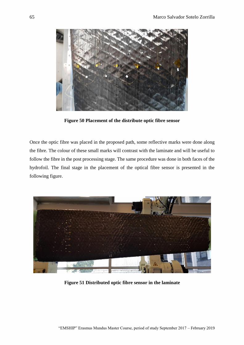
65 Marco Salvador Sotelo Zorrilla
“EMSHIP” Erasmus Mundus Master Course, period of study September 2017 – February 2019
Figure 50 Placement of the distribute optic fibre sensor
Once the optic fibre was placed in the proposed path, some reflective marks were done along
the fibre. The colour of these small marks will contrast with the laminate and will be useful to
follow the fibre in the post processing stage. The same procedure was done in both faces of the
hydrofoil. The final stage in the placement of the optical fibre sensor is presented in the
following figure.
Figure 51 Distributed optic fibre sensor in the laminate

66 Automated manufacture of shape-adaptive large hydrofoil
Master Thesis developed at University of New South Wales, Australia; and at University of Rostock, Germany
The following step before continuing with the lamination was to test the connection of the fibre.
To perform this task, both ends of the optical fibre were welded and then connected to the
interrogator (ODiSI-B). In this step the measurement obtained was the initial signature of the
optical fibre without any perturbation. This procedure was repeated for the two sensors
installed. Once the sensors were checked and verified that worked properly, the lamination of
the final layers continued. To ensure the functionality of the distributed optical sensor, during
the lamination of the final layers some strain measurements were performed.
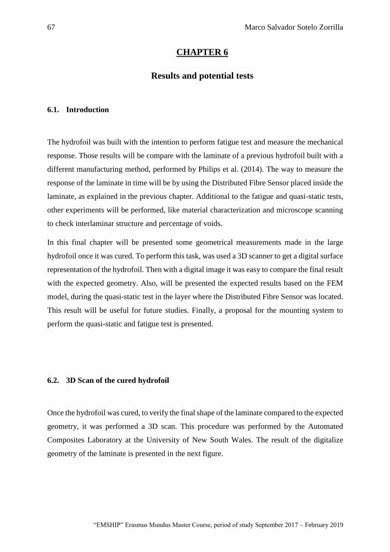
67 Marco Salvador Sotelo Zorrilla
“EMSHIP” Erasmus Mundus Master Course, period of study September 2017 – February 2019
CHAPTER 6
Results and potential tests
6.1. Introduction
The hydrofoil was built with the intention to perform fatigue test and measure the mechanical
response. Those results will be compare with the laminate of a previous hydrofoil built with a
different manufacturing method, performed by Philips et al. (2014). The way to measure the
response of the laminate in time will be by using the Distributed Fibre Sensor placed inside the
laminate, as explained in the previous chapter. Additional to the fatigue and quasi-static tests,
other experiments will be performed, like material characterization and microscope scanning
to check interlaminar structure and percentage of voids.
In this final chapter will be presented some geometrical measurements made in the large
hydrofoil once it was cured. To perform this task, was used a 3D scanner to get a digital surface
representation of the hydrofoil. Then with a digital image it was easy to compare the final result
with the expected geometry. Also, will be presented the expected results based on the FEM
model, during the quasi-static test in the layer where the Distributed Fibre Sensor was located.
This result will be useful for future studies. Finally, a proposal for the mounting system to
perform the quasi-static and fatigue test is presented.
6.2. 3D Scan of the cured hydrofoil
Once the hydrofoil was cured, to verify the final shape of the laminate compared to the expected
geometry, it was performed a 3D scan. This procedure was performed by the Automated
Composites Laboratory at the University of New South Wales. The result of the digitalize
geometry of the laminate is presented in the next figure.
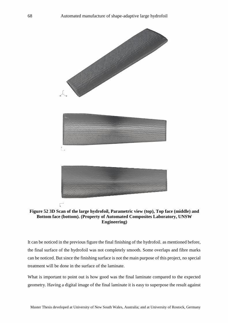
68 Automated manufacture of shape-adaptive large hydrofoil
Master Thesis developed at University of New South Wales, Australia; and at University of Rostock, Germany
It can be noticed in the previous figure the final finishing of the hydrofoil. as mentioned before,
the final surface of the hydrofoil was not completely smooth. Some overlaps and fibre marks
can be noticed. But since the finishing surface is not the main purpose of this project, no special
treatment will be done in the surface of the laminate.
What is important to point out is how good was the final laminate compared to the expected
geometry. Having a digital image of the final laminate it is easy to superpose the result against
Figure 52 3D Scan of the large hydrofoil, Parametric view (top), Top face (middle) and
Bottom face (bottom). (Property of Automated Composites Laboratory, UNSW
Engineering)
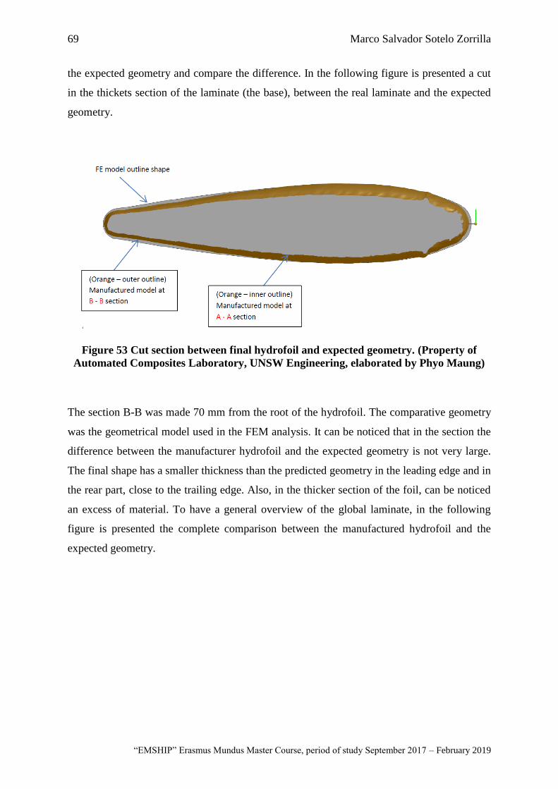
69 Marco Salvador Sotelo Zorrilla
“EMSHIP” Erasmus Mundus Master Course, period of study September 2017 – February 2019
the expected geometry and compare the difference. In the following figure is presented a cut
in the thickets section of the laminate (the base), between the real laminate and the expected
geometry.
Figure 53 Cut section between final hydrofoil and expected geometry. (Property of
Automated Composites Laboratory, UNSW Engineering, elaborated by Phyo Maung)
The section B-B was made 70 mm from the root of the hydrofoil. The comparative geometry
was the geometrical model used in the FEM analysis. It can be noticed that in the section the
difference between the manufacturer hydrofoil and the expected geometry is not very large.
The final shape has a smaller thickness than the predicted geometry in the leading edge and in
the rear part, close to the trailing edge. Also, in the thicker section of the foil, can be noticed
an excess of material. To have a general overview of the global laminate, in the following
figure is presented the complete comparison between the manufactured hydrofoil and the
expected geometry.

70 Automated manufacture of shape-adaptive large hydrofoil
Master Thesis developed at University of New South Wales, Australia; and at University of Rostock, Germany
It can be noticed that the discrepancy between the manufactured hydrofoil and the expected
geometry y relatively low. The most noticeable difference is the shrinkage in the leading edge,
that is in the order of -7 mm. The green area which represents the deviation between -2 to 1
mm covers a largest portion of the hydrofoil y both faces. On the other hand, there is a blue
area on both faces which means a thickness shrinkage in the order of -4 mm compared to the
desirable geometry. This second shrinkage could be potentially solved by extending in the
horizontal direction the perimeter boundaries for the intermediate layers. In general, the overall
laminate match quite accurately the expected geometry, with a general variation between real
and desire thickness between 1 to -4 mm. normally composite structures are made in female
moulds, therefore the finishing of the laminate is almost perfect. For the case of this
manufacturing technique mould used was the fibreglass core, hence the finishing was not
expected to be precise. The potential improvements for future manufactures of this kind of
laminate could be a more refine definition of the boundaries.
Figure 54 Comparison between final hydrofoil and expected geometry. Top face (top),
and bottom face (bottom) (Property of Automated Composites Laboratory, UNSW
Engineering, elaborated by Phyo Maung)
Leading Edge
Trailing Edge
Leading Edge
Trailing Edge
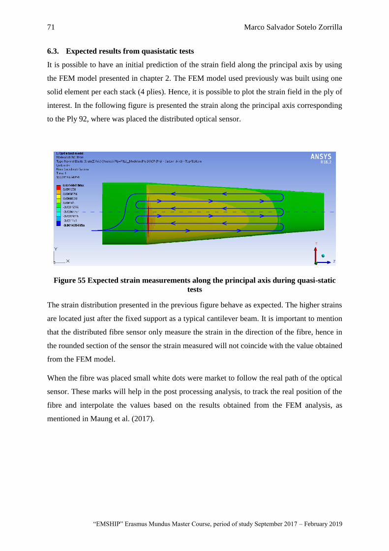
71 Marco Salvador Sotelo Zorrilla
“EMSHIP” Erasmus Mundus Master Course, period of study September 2017 – February 2019
6.3. Expected results from quasistatic tests
It is possible to have an initial prediction of the strain field along the principal axis by using
the FEM model presented in chapter 2. The FEM model used previously was built using one
solid element per each stack (4 plies). Hence, it is possible to plot the strain field in the ply of
interest. In the following figure is presented the strain along the principal axis corresponding
to the Ply 92, where was placed the distributed optical sensor.
Figure 55 Expected strain measurements along the principal axis during quasi-static
tests
The strain distribution presented in the previous figure behave as expected. The higher strains
are located just after the fixed support as a typical cantilever beam. It is important to mention
that the distributed fibre sensor only measure the strain in the direction of the fibre, hence in
the rounded section of the sensor the strain measured will not coincide with the value obtained
from the FEM model.
When the fibre was placed small white dots were market to follow the real path of the optical
sensor. These marks will help in the post processing analysis, to track the real position of the
fibre and interpolate the values based on the results obtained from the FEM analysis, as
mentioned in Maung et al. (2017).

72 Automated manufacture of shape-adaptive large hydrofoil
Master Thesis developed at University of New South Wales, Australia; and at University of Rostock, Germany
This page is intentionally left blank.
73 Marco Salvador Sotelo Zorrilla
“EMSHIP” Erasmus Mundus Master Course, period of study September 2017 – February 2019
CONCLUSIONS
A state of the art composite manufacturing method for thick laminates was studied in this work.
Based on this investigation the following conclusions can be drawn:
• It is possible to use simplified FEM models combined with Genetic Algorithm to
optimize the orientation of a thick laminate. In this work was used a simplified shell
element model to represent the thick laminate, reducing significantly the computational
time. The objective function of the optimization was to achieve the rigidity of a
reference large hydrofoil proposed by Phillips et al. (2014). The optimized large
hydrofoil presents relative difference in the tip deformation of 4.21% in the leading
edge and 1.65% in the trailing edge, compared to the reference value.
• Automated manufacturing techniques in composites like Automated Fibre Placement
reduce significantly the human error during the lamination. Due to the high material
deposition rate, the productivity of the manufacturing process increases significantly
compared to traditional lamination processes. However, even if this manufacturing
process is fully automated, it is necessary the assistant of an experience operator during
the lamination.
• Intrinsic defects proper from AFP techniques like overlapping, gaps and wrapping were
present in the thick laminate of the large hydrofoil. The effect of this unintentional
defects in the laminate will be only possible to measure during mechanical tests.
However, isolated defects do not affect the global mechanical behaviour of the
laminate, according to Woigk et al. (2018)
• Based on previous experiments performed in the Advanced Composites laboratory at
UNSW regarding curing of thick prepreg laminates, the appropriate curing cycle for the
large hydrofoil was determined. The large hydrofoil manufactured in this work was
cured using the proposed curing cycle, giving as result a complete cure laminate under
visual inspection. However further experiments are needed to prove the complete level
of cure of the laminate and material properties.
74 Automated manufacture of shape-adaptive large hydrofoil
Master Thesis developed at University of New South Wales, Australia; and at University of Rostock, Germany
• Distributed optic fibre sensor is a monitoring technique which has a high ratio of
simplicity over data acquisition. The procedure to install the distributed optical fibre
sensor is relatively simple and does not require a large amount of wires and. The optical
fibre was placed between the ply 92 and 93 to measure internal strains without
compromising the integrity of the laminate. The possible amount of data acquired by
the installed distributed fibre sensor could go up to 250 Hz. Giving a huge amount of
information regarding the strain field in real time, which could be interesting for time
dependant tests.
• Based on a 3D scan analysis, it was determined a reasonable good agreement comparing
the real geometry of the cured hydrofoil with the expected geometry of the 3D model.
However, in the digital geometry of the real hydrofoil can be noticed that the finishing
surface is not completely smooth. The most notorious discrepancy is in the leading
edge, where the shrinkage of the real hydrofoil is about -7 mm compared to the desired
model. Another noticeable area is close to the trailing edge, where the shrinkage is
around -4 mm. Besides these differences and the surface finishing of the cured laminate,
the overall geometry has a good approximation to the desire geometry.
75 Marco Salvador Sotelo Zorrilla
“EMSHIP” Erasmus Mundus Master Course, period of study September 2017 – February 2019
FURTHER WORK
This work was the first part of a whole project regarding the mechanical response of a
composite large hydrofoil under fatigue loads. Hence a set of experiments and tests are already
planned for this specimen.
The first set of experiments is a quasi-static cantilever test, using a unidirectional hydraulic
actuator which has a maximum capacity of 500 KN. The goal of this test is to validate the
results obtained with the FEM model. To measure the deformation in the tip of the hydrofoil,
dial gauges will be used.
The following se of experiments are bases on the experiments performed by Nanayakkara et
al. (2015). In this work they made fatigue test on a large composite hydrofoil, dividing the
fatigue loads in 4 groups. On each group they increased significantly the peak load and the
number of cycle decrease. The same procedure will be adopted for the set of experiments for
the large hydrofoil manufactured in this work.
The mechanical response is expected to be different than the reference works because the
material and manufacturing process used in this work was different. However, the results
presented by Nanayakkara et al. (2015) and Phillips et al. (2014) are significant reference
values to demonstrate the potential improvement of thick composite structures by using
advanced manufacturing techniques.
The distributed optical fibre will be used as a strain measurement instrument during the fatigue
tests. With the huge amount of data capable to acquire the installed sensor embedded in the
laminate, it is possible to perform very accurate analysis and comparisons with FEM models.

76 Automated manufacture of shape-adaptive large hydrofoil
Master Thesis developed at University of New South Wales, Australia; and at University of Rostock, Germany
This page is intentionally left blank

77 Marco Salvador Sotelo Zorrilla
“EMSHIP” Erasmus Mundus Master Course, period of study September 2017 – February 2019
ACKNOWLEDGEMENTS
I would like to express my gratitude to my thesis supervisor Prof. Gangadhara Prusty for the
guidance and giving me the opportunity to join this cutting-edge project at the University of
New South Wales, Sydney. Also, special thanks to Phyo Maung and Dr. Ebrahim Oromiehie
for helping me during the design step and preparation of the manufacturing tool, without their
contribution nothing of this could be possible.
Furthermore, I would like to thank all the professors from the different institutions that
contributed in the learning process through all the EMship program. Special thanks to Prof.
Philippe Rigo and Christine Reynders for the continuous support along the whole program
which has been an invaluable experience for me.
Finally, I would like to thank my family, Marco, Briseida and Ernesto for the continuous
support through all the master’s program. Also, my sincerely thanks to Domenica Ruiz for the
emotional support and continuous encouraging, without all of them I would not be able to
succeed.
This thesis was developed in the frame of the European Master Course in “Integrated Advanced
Ship Design” named “EMSHIP” for “European Education in Advanced Ship Design”, Ref.:
159652-1-2009-1-BE-ERA MUNDUS-EMMC.

78 Automated manufacture of shape-adaptive large hydrofoil
Master Thesis developed at University of New South Wales, Australia; and at University of Rostock, Germany
This page is intentionally left blank
79 Marco Salvador Sotelo Zorrilla
“EMSHIP” Erasmus Mundus Master Course, period of study September 2017 – February 2019
Bibliography
Automated Dynamics. 2014. Fiber Placement Manager. User Manual, Automated Dynamics.
Bannister, M. 2001. “Challenges for composites into the next millennium.” Composites- Part
A: applied science and manufacture 901-910.
Campbell F. 2003. Manufacturing processes for advanced composites. Elsevier Science &
Technology.
Davis C., Knowle M. & Swanton G.,. 2018. Evaluation of a Distributed Fibre Optic Strain
Sensing System for a Full-Scale Fatigue Testing. Technical Report, Aerospace
Division. Defense Science and Technology Group.
Davis C., Norman P., Kopczyk J. & Rowlands D. 2012. Initial Trial using Embedded Fibre
Bragg Grating for Distributed Strain Monitoring in a Shae Adaptive Composite Foil.
Technical report, Air Vahicle Division, Defence Science and Technology Organization.
Ducoin A., Astolfi J. & Sigrist J. 2012. “An experimental analysis of fluid structure interaction
of a flexible hydrofoil in various flw regimes including cavitatinf flow.” European
Journal of Mechanics 63-73.
Giovannetti. 2017. “Fluid structure interaction testing, modelling and development of Passive
Adaptive Composite foils.” PhD Thesis. Faculty of Engineering and Environment.
Southampton: University of Southampton.
Gower M., Shaw R., Broughton W. 2016. Effect of cure cycle on the properties of thick
carbo/epoxy laminates. Middlesex, UK: National Physical Laboratory.
Guemes J. & Fernandez A. 2010. “Optical Fiber Distributes Sensing. Physical Priciples and
Applications.” Journal of Structural Health Monitoring 233-245.
Herath M. 2016. “Optimisation of composite marine propellers and hydrofoils.” PhD thesis.
Faculty of Mechanical and Manufacture Engineering. Sydney: University of New
South Wales.
Herath M., Natarajan S., prusty G. & John N. 2015. “Isogeometric analysis and Genetic
Algorithm for shape-adpative composite marine propellers.” Computer Methods in
Applied Mechanics and Engineering 835-860.

80 Automated manufacture of shape-adaptive large hydrofoil
Master Thesis developed at University of New South Wales, Australia; and at University of Rostock, Germany
Herath M., Natarajan S., Prusty G. & John N. 2013. “Smoothed Finite Element and Genetic
Algorithm based optimization for Shape Adaptive Composite Marine Propellers.”
Composite Structures.
Jackson K. 1990. Workshop of scale effects in composite materials and structures. NASA
Conference Publication, NASA.
Kozaczuk K. 2016. “Automated fiber placement systems overview.” Transactions of the
Institute of Aviation. Warsaw: Institute of Aviation. 52-59.
Lin C., and Y. Lee. 2014. “Stacking sequence optimization of laminated composite structures
using genetic algorithm with local improvement.” Composite Structures 339-345.
Loos A. & Springer G. 1983. “Curing of Epoxy Matrix Composites.” Journal of Composite
Materials 135-169.
LUNA Technologies. 2017. ODiSI-B Data sheet. Broachure, LUNA. https://lunainc.com/wp-
content/uploads/2016/07/ODB5_DataSheet_Rev13_020217.pdf.
Maung P., Prusty G., Rajan G., Li E., Phillips A. and St John N. 2017. “Distributed strain
measurement using fibre optics in a high performance composite hydrofoil.”
International Conference on Composite Materials. Xi'an: Chinese Society for
Composite Materials.
Molland A., Turnock S. & Hudson D. 2011. Ship Resistance and Propulsion. Cambridge
University Press.
Mulcahy N., Prusty G. & Gardiner C. 2011. “Flexible composite hydrofoils and propeller
blades.” International journal of small craft technology 39-46.
Mulcahy N., Prusty G. & Gardiner C. 2010. “Hydroeslastic tailoring of flexible composite
propellers.” Ship and Offshore Structures 359-370.
Nanayakkara A., Phillips A., Russo S., Cairns R. & John N. 2015. “Mechanical Behaviour of
Thick Composite Hydrofoil under Fatigue Loading.” SAMPE Conference Proceedings.
Baltimore: Society for the Advancement of Material and Process Engineering.
Onwubolu B., and Babu G. 2013. New Optimization Techniques in Engineering. Springer.
Park Advanced Composites Materials. n.d. Material data sheet, Prepreg E-752.
https://parkelectro.com/aerospace-products/e-752/.
81 Marco Salvador Sotelo Zorrilla
“EMSHIP” Erasmus Mundus Master Course, period of study September 2017 – February 2019
Phillips A., Nanayakkara A., Russo S., Cairns R. John N. 2014. “Mechanical response of a
thick composite hydrofoil.” 8th Australasian Congress on Applied Mechanics
(ACAM8). 1-8.
White J., Muang P., David M., Phillips A., John N. & Prusty G. 2017. “Hydrofoil Manufacture
with Automated Fibre Placement.” 9TH Australasian Congress on Applied Mechanics.
National Committee on Applied Mechanics.
Woigk W., Hallett S., Jone M., Kuhtz M., Horning A. & Gude M. 2018. “Experimental
investigation of the effect of defects in Automated Fibre Placement produced composite
laminates.” Composite Structures 1004-1017.
Wu Q., Huang B., Wang G. & Gao Y. 2015. “Experimental and numerical investigation of
hydroelastic response of a flexible hydrofoil in cavitatinf flow.” International Journal
of Multiphase Flow 19-33.
Young Y., Motley M., Barber R., Cha E. & Garg N. 2016. Adaptive Composite Marine
Propulsors and Turbines: Progress and Challenges. Applied Mechanics Reviews ,
ASME.
Zarruk G., Brandner P., Pearce B. & Phillips A. 2014. “Experimental study of the steady fluid-
structure interaction of flexible hydrofoils.” Journal of Fluid and Structures (Journal)
326-343.