autocirc instant hot water pump model: act e10 remove the existing flexible line connection to the...
TRANSCRIPT

INSTRUCTION MANUAL 6-71-075-109
REVISION A
Autocirc® Instant Hot Water PumpModel: ACT E10


3
Preparation for Installation: Assemble the parts and tools required: 1. Open and inspect Autocirc pump package. 2. Autocirc pump package includes the pump with a built-in timer, a 6ft. cord, and wall mounting bracket. 3. Two stainless steel flexible hoses (1/2” x 3/8”) - length as required. (sold separately) 4. Adjustable wrench and screwdriver. 5. Select the sink under which the Autocirc pump is to be locat e d (the sink where hot water takes longest to arrive).
Installation Step 1 If not already available, install a 115 Volt/ 60Hz outlet within six (6) feet of the installation site (the faucet/tap farthest from the water heater), as the Autocirc is supplied with a 6 ft. long, grounded cord. The Autocirc pump requires only 14 watts and 0.3 amps of power (see Fig. 1).
Step 2 Autocirc pump and mounting bracket come preassembled. Remove mounting bracket from Autocirc by carefully sliding the mounting bracket off the (4) supporting pins on the Autocirc pump body. Fasten the mounting to the wall under the sink using the wall bracket provided in the Autocirc kit. Mount Autocirc pump into position by aligning and securing mounting bracket to the (4) support pins. Be sure the pump timer is turned toward the front and is accessible for setting and changing the time (see Fig. 2). The pump must be installed only in a vertical position as shown.
Step 3 Close the under sink hot and cold water riser shut-off valves and open the hot and cold water faucets/taps to relieve the water pressure. Close the water faucets/taps after pressure has bled from the lines.
Note: in some older homes, the riser shut-off valves may be difficult to shut off completely. If this is the case turn the water off at the main water inlet valve to the house.
CAUTION: Do Not fasten pump to a thin wood panel wall as this might create a vibration noise when the pump is operating.
Figure 1
Figure 2
Figure 3

4
Remove the existing flexible line connection to the hot and cold water faucet/tap threaded nipples (see Fig. 3). (TIP: Mark the hot and cold water flexible lines to easily identify them).
Note: If necessary, replace the existing flexible hoseswith new stainless steel braided flexible hoses in the lengths required. Step 4Screw on the two existing 1/2” hose connections to the corresponding hot and cold sides of the pump housing (see Fig. 4). Be sure not to “kink” these existing hose lines during bending which may prevent adequate flow and/or cause the valves to break.
Note: It is recommended that the rubber washers in the hose connections be inspected to ensure theyare in reusable condition. If not, they should be replaced.
Step 5Screw on the 3/8” end of the purchased flexible hoses to the 3/8” connections on the pump housing. Screw on the 1/2” end of these same two hoses to the underside of the hot and cold water faucets/taps making sure to match the hot and cold sides marked on the pump housing with the corresponding faucet/tap. Be sure the hot side connection hose is attached to the hot water faucet/tap and the cold water side connec-tion is attached to the cold water faucet/tap. Be sure the hoses used are long enough to allow the pump to be positioned as originally planned. ( see Fig. 5)
Step 6Be sure the screw ring attaching the motor to the pump housing is securely hand tightened. Do not over tighten the screw ring. Open the faucet/tap hot and cold riser shut off valves to insure there are no water leaks at any connections.
Step 7Plug the pump cord into the wall outlet and start up the pump system (see next page).
Figure 4
Figure 5
CAUTION: Fasten screw ring until tight to prevent leakage.
5
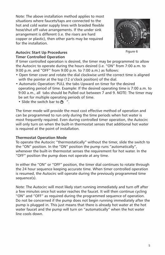
Autocirc Start Up ProceduresTimer Controlled OperationIf timer controlled operation is desired, the timer may be programmed to allow the Autocirc to operate during the hours desired (i.e. “ON” from 7:00 a.m. to 9:00 p.m. and “OFF” from 9:00 p.m. to 7:00 a.m.) as follows:• Open timer cover and rotate the dial clockwise until the correct time is aligned
with the pointer at the top (12 o’clock position) of the dial.• Automatic Operation: PULL the tabs Upward on timer for the desired
operating period of time. Example: If the desired operating time is 7:00 a.m. to 9:00 a.m., all tabs should be Pulled out between 7 and 9. NOTE: The timer may be set for multiple operating periods of time.• Slide the switch bar to “ ”.
The timer mode will provide the most cost effective method of operation and can be programmed to run only during the time periods when hot water is most frequently required. Even during controlled timer operation, the Autocirc will only turn on when the built-in thermostat senses that additional hot water is required at the point of installation.
Thermostat Operation ModeTo operate the Autocirc “thermostatically” without the timer, slide the switch to the “ON” position. In the “ON” position the pump runs “automatically”, whenever the built-in thermostat senses the requirement for hot water. In the “OFF” position the pump does not operate at any time.
In either the “ON” or “OFF” position, the timer dial continues to rotate through the 24 hour sequence keeping accurate time. When timer controlled operation is resumed, the Autocirc will operate during the previously programmed time sequence(s).
Note: The Autocirc will most likely start running immediately and turn off after a few minutes once hot water reaches the faucet. It will then continue cycling “ON” and “OFF” as required during the programmed sequence of operation. Do not be concerned if the pump does not begin running immediately after the pump is plugged in. This just means that there is already hot water at the hot water faucet and the pump will turn on “automatically” when the hot water line cools down.
Figure 6
Note: The above installation method applies to most situations where faucets/taps are connected to the hot and cold water supply lines with braided flexible hose/shut off valve arrangements. If the under sink arrangement is different (i.e. the risers are hard copper or plastic), then other parts may be required for the installation.


Xylem Inc.
3878 S. Willow, Suite 104Fresno, CA 93725Tel: (559) 265-4730 (800) 554-6853Fax: (559) 265-4740 (800) 453-7523www.xyleminc.com/brands/laingthermotech
Laing Thermotech is a trademark of Xylem Inc. or one of its subsidiaries. © 2012 Xylem, Inc. 6-71-075-109A July 2012