autocaptm adaptive capacitor controller and - … hi-voltage corp. 4000 east 116th st. ... 5.7.2...
TRANSCRIPT

Visit www.joslynhivoltage.com for latest revision of manual/SmartSet software
POWERFLEX®
Instruction Manual 4400 and 4500 Series
AutoCapTM Adaptive Capacitor Controller and
SmartSetTM Application Software

2 H2338 REV. F 5/10/07

3 H2338 REV. F 5/10/07
Proprietary Notice: Fisher Pierce personnel and customers shall use this manual as a guide to install, operate and maintain the equipment herein. Fisher Pierce reserves the right to make changes without notice in the specifications and material contained herein, and shall not be responsible for any damages, including consequential, caused by reliance on the materials presented. The drawings, instructions and specifications contained herein are property of Fisher Pierce and shall not be reproduced in whole or in part without prior written approval, nor be implied to grant any license to make, use or sell equipment in accordance herein.
! Caution: The equipment covered by this publication must be selected for
a specific application and it must be installed, operated, and maintained by qualified persons who are thoroughly trained and who understand any hazards that may be involved. This publication is written only for such qualified persons and is not intended to be a substitute of adequate training and experience in safety procedures for this type of equipment.
First Printing – June, 1996
Copyright 2000
All Rights Reserved
Joslyn Hi-Voltage Corp. 4000 East 116th St.
Cleveland, Ohio 44105-4398 Phone (216) 271-6600
Fax (216) 341-3615 Toll-Free (800) 621-5875 www.joslynhivoltage.com Email: [email protected]
Printed in USA

4 H2338 REV. F 5/10/07
Table of Contents INTRODUCTION..............................................................................................................................................................9
I. USE AND CONTENTS OF THIS MANUAL...................................................................................................................9 II INSTRUCTION MANUAL AND SMARTSET SOFTWARE REVISION INFORMATION ......................................................9
SECTION 1 .....................................................................................................................................................................10 AUTOCAP CONTROLLER AND SMARTSET APPLICATION SOFTWARE OVERVIEW...........................................................10 1.1 BASIC CONTROLLER OPERATION .....................................................................................................................10 1.2 AUTOCAP SERIES 4400 AND SERIES 4500........................................................................................................11
SECTION 2 .....................................................................................................................................................................12 AUTOCAP SPECIFICATIONS ...........................................................................................................................................12 2.1 ELECTRICAL.....................................................................................................................................................12 2.2 MECHANICAL...................................................................................................................................................12 2.3 ENVIRONMENTAL.............................................................................................................................................13 2.4 MEASUREMENT PERFORMANCE .......................................................................................................................13 2.5 INPUT DATA LOG STORAGE .............................................................................................................................14
SECTION 3 .....................................................................................................................................................................15 AUTOCAP FUNCTIONS AND OPERATION........................................................................................................................15 3.1 PRIMARY AND OVERRIDE CONTROL FUNCTIONS .............................................................................................15
3.1.1 Primary Control Mode Operation...............................................................................................................15 3.1.1.1 VAr Control.................................................................................................................................................16 3.1.1.2 Voltage Control ...........................................................................................................................................19 3.1.1.3 Current Control...........................................................................................................................................19 3.1.1.4 Time Control ...............................................................................................................................................19 3.1.1.5 Temperature Control...................................................................................................................................20 3.1.1.6 SCADA Control ...........................................................................................................................................20 3.1.1.7 No-Op (No Operation) ................................................................................................................................21
3.1.2 OVERRIDE CONTROL MODE OPERATION.........................................................................................................21 3.1.2.1 Voltage Override .........................................................................................................................................22 3.1.2.2 Time Override .............................................................................................................................................22 3.1.2.3 Temperature Override.................................................................................................................................22 3.1.2.4 SCADA Override .........................................................................................................................................23 3.1.3 Season / Dates .............................................................................................................................................23
3.2 ADAPTIVE CONTROL FUNCTIONS.....................................................................................................................23 3.2.1 PhaseFind ...................................................................................................................................................23 3.2.2 Adaptive VAr Control Description ..............................................................................................................24 3.2.3 Adaptive Voltage Guard Description ..........................................................................................................25
3.3 ADDITIONAL CONTROL FUNCTIONS .................................................................................................................26 3.3.1 Voltage Bias Control ...................................................................................................................................26 3.3.2 Reverse Power Control ...............................................................................................................................26
3.4 PROTECTIVE FUNCTIONS..................................................................................................................................27 3.4.1 Reversed Trip/Close Detection....................................................................................................................28 3.4.2 Anti-Hunt.....................................................................................................................................................28 3.4.3 Undervoltage Inhibit ...................................................................................................................................28 3.4.4 Daily Close Count Limit..............................................................................................................................28 3.4.5 Neutral Current Lockout .............................................................................................................................29 3.4.6 Power-Up Trip ............................................................................................................................................29 3.4.7 Auxiliary High Voltage Trip........................................................................................................................29
3.5 RECORDING FUNCTIONS...................................................................................................................................29 3.5.1 Load Data Recording ..................................................................................................................................30 3.5.2 Daily Summary Log.....................................................................................................................................31 3.5.3 Events Log...................................................................................................................................................31

5 H2338 REV. F 5/10/07
3.6 MONITORING/OPERATING FUNCTIONS.............................................................................................................31 3.7 REPORT GENERATION FUNCTIONS ...................................................................................................................31 3.8 LOCAL INDICATIONS AND MANUAL OPERATION..............................................................................................31 3.9 PANELSET FRONT PANEL PROGRAMMING FUNCTIONS ....................................................................................32 3.10 COMMUNICATIONS OPTION..............................................................................................................................33
SECTION 4 .....................................................................................................................................................................34 SMARTSET INSTALLATION AND STARTUP .....................................................................................................................34 4.1 NECESSARY EQUIPMENT..................................................................................................................................34 4.2 INSTALLING SMARTSET ...................................................................................................................................34 4.3 CONNECTING A PC TO THE AUTOCAP CONTROLLER........................................................................................35
SECTION 5 .....................................................................................................................................................................36 SMARTSET APPLICATION SOFTWARE............................................................................................................................36 5.1 OVERVIEW .......................................................................................................................................................36
5.1.1 Controller Programming.............................................................................................................................36 5.1.2 Default Program .........................................................................................................................................37 5.1.3 File Definition .............................................................................................................................................37
5.2 USING SMARTSET APPLICATION SOFTWARE ..........................................................................................................37 5.2.1 Main Menu Screen ......................................................................................................................................39
5.3 PCC SETUP (CONTROLLER PROGRAMMING)....................................................................................................40 5.3.1 View Setup Screen .......................................................................................................................................41 5.3.2 Site/Limits (Control Selections)...................................................................................................................42 5.3.3 Control Config (Control Mode and Season Selection)................................................................................43 5.3.4 Data Log Config (Recorded Data Selection) ..............................................................................................44 5.3.5 Holidays / Daylight Saving Time................................................................................................................46 5.3.6 Adaptive Test (Adaptive Functions Management).......................................................................................47
5.3.6.1 Starting The Adaptive Test....................................................................................................................................... 47 5.3.6.2 Pre-Programming The Adaptive Test For Auto Start ............................................................................................... 49 5.3.6.3 If The Adaptive Test Is Unsuccessful....................................................................................................................... 49
5.3.7 Save Setup ...................................................................................................................................................50 5.3.8 Print Setup...................................................................................................................................................50 5.3.9 Send to PCC (Program Controller) ............................................................................................................50
5.3.10 Comm Protocol (4500 Series Only) .................................................................................................................... 50 5.3.11 Setup Comments ................................................................................................................................................. 51
5.4 MONITOR / OPERATE (VIEW REAL -TIME CONDITIONS AND SET COMMANDS .................................................51 5.4.1 Present Readings.............................................................................................................................................51 5.4.2 Present Status..................................................................................................................................................51 5.4.3 Site Data..........................................................................................................................................................52 5.4.4 Control Status/Settings....................................................................................................................................52 5.5 Data Access.......................................................................................................................................................52 5.5.1 Retrieve from PCC..........................................................................................................................................52
5.6 SEND PCC TIME (SET CONTROLLER CLOCK)...................................................................................................54 5.7 SMARTSET SETUP ............................................................................................................................................55
5.7.1 PCC Model Selection ..................................................................................................................................55 5.7.2 Line Voltage and Frequency .......................................................................................................................56 5.7.3 Southern Hemisphere DST ..........................................................................................................................56 5.7.4 Date Format ................................................................................................................................................56 5.7.5 Communication Method ..............................................................................................................................56 5.7.6 Direct Connect/Optical Sensor or Modem ..................................................................................................56 5.7.7 Baud Rate ....................................................................................................................................................57 5.7.8 Modem Dial-Up directory:..........................................................................................................................57
SECTION 6 .....................................................................................................................................................................58 AUTOCAP HARDWARE DESCRIPTION............................................................................................................................58 6.1 HARDWARE OPERATION ..................................................................................................................................58

6 H2338 REV. F 5/10/07
6.1.1 Battery Backed RAM Operation..................................................................................................................58 6.2 CONSTRUCTION FEATURES ..............................................................................................................................59
6.2.1 Enclosure.....................................................................................................................................................59 6.2.2 Circuit Boards .............................................................................................................................................59
6.3 FRONT PANEL FEATURES .................................................................................................................................59 6.3.1 Automatic/Manual Toggle Switch ...............................................................................................................59 6.3.2 Trip/Close Toggle Switch ............................................................................................................................60
6.3.2.1 Trip Position ....................................................................................................................................................... 60 6.3.2.2 Close Position ..................................................................................................................................................... 60
6.3.3 Test Jacks ....................................................................................................................................................61 6.3.3.1 Line Test Jack ..................................................................................................................................................... 61 6.3.3.2 Neutral Test Jack ................................................................................................................................................ 61 6.3.3.3 Load Fuse Jack.................................................................................................................................................... 61 6.3.3.4 Sensor High and Sensor Low Jacks .................................................................................................................... 62
6.3.4 Fuses ...........................................................................................................................................................62 6.3.5 LED Indicators............................................................................................................................................62
6.3.5.1 AC Power LED................................................................................................................................................... 62 6.3.5.2 Processor OK LED ............................................................................................................................................. 62 6.3.5.3 Reverse Power LED............................................................................................................................................ 62 6.3.5.4 Trip Inhibit LED ................................................................................................................................................. 62 6.3.5.5 Trip LED............................................................................................................................................................. 63 6.3.5.6 Close LED .......................................................................................................................................................... 63 6.3.5.7 Close Inhibit LED............................................................................................................................................... 63 6.3.5.8 Receive and Transmit LED’s.............................................................................................................................. 63
6.3.6 LCD Display (Optional)..............................................................................................................................63 6.3.7 Close Counter (Optional)............................................................................................................................63 6.3.8 Communications Ports ................................................................................................................................63
6.3.8.1 RS-232 Communication Port .............................................................................................................................. 64 6.3.8.2 Optical Communication Port (Optional) ............................................................................................................. 64
6.4 OTHER HARDWARE FEATURES ...............................................................................................................................64 6.4.1 Neutral Current LED and Reset Switch (Optional).....................................................................................64 6.4.2 Controller Vent............................................................................................................................................64 6.4.3 Ground Lug (Optional) ...............................................................................................................................64 6.4.4 12 Vdc Power Supply Connector (Series 4500 only)...................................................................................64 6.4.5 Solenoid Operated Switches........................................................................................................................64
SECTION 7 .....................................................................................................................................................................65 AUTOCAP INSTALLATION INSTRUCTIONS .....................................................................................................................65 7.1 INSTALLATION INSTRUCTIONS.................................................................................................................................65
7.1.1 Pre-Installation Notes .................................................................................................................................65 7.1.2 Model Number Guide ..................................................................................................................................65 7.1.3 For All Installations ....................................................................................................................................65 7.1.4 Line Current Sensing Installations..............................................................................................................66 7.1.5 Neutral Current Sensing Installations.........................................................................................................66 7.1.6 Meter Socket Installations ...........................................................................................................................66 7. 1.7 Pole or Wall Mount Installations ................................................................................................................67
7.2 FIELD TESTS.................................................................................................................................................68 7.2.1 Power Check ...............................................................................................................................................68 7.2.2 Reverse Power Check (for controllers with current signal input)...............................................................68 7.2.3 Close / Trip Check.......................................................................................................................................68 7. 2.4 Power Flow Check (for controllers with current signal input) ..................................................................69 7.2.5 FINAL SETTINGS.......................................................................................................................................70
7.3 INSTALLATION DIAGRAMS......................................................................................................................................71 SECTION 8 .....................................................................................................................................................................76
TROUBLESHOOTING GUIDE ...........................................................................................................................................76 8.1 No power to controller (“AC POWER” and other LED’s not on)..............................................................76
7 H2338 REV. F 5/10/07
8.2 “PROCESSOR OK” LED not flashing (“AC POWER” LED on) ..............................................................76 8.3 Excessive Bank Switching ...........................................................................................................................76 8.4 Infrequent Bank Switching ..........................................................................................................................76 8.5 No Bank Switching ......................................................................................................................................76 8.6 Computer is not communicating with controller .........................................................................................77 8.7 Controller in Backup Voltage Mode............................................................................................................77 8.8 RAM Battery Failure ...................................................................................................................................77
SECTION 9 .....................................................................................................................................................................78 4400 MODEL NUMBER AND ORDERING INFORMATION .................................................................................................78 4500 MODEL NUMBER AND ORDERING INFORMATION .................................................................................................82
SECTION 10 ...................................................................................................................................................................86 DNP3.0 COMMUNICATION SETUP AND OPERATION......................................................................................................86 10.1 OVERVIEW .......................................................................................................................................................86 10.2 DNP 3.0 SETTINGS...........................................................................................................................................87
10.2.1 Programmable Capacitor Controller Address (PCC).................................................................................87 10.2.2 PCC Serial Number.....................................................................................................................................87 10.2.3 Group Address.............................................................................................................................................87 10.2.4 Master Control Address ..............................................................................................................................87 10.2.5 Baud Rate ....................................................................................................................................................87 10.2.6 Comm Rev Number......................................................................................................................................88 10.2.7 Comm CheckSum........................................................................................................................................88
10.3 ALARM SETTINGS ............................................................................................................................................88 10.3.1 High Voltage Alarm ....................................................................................................................................88 10.3.2 Low Voltage Alarm......................................................................................................................................88 10.3.3 Alarm Deadband .........................................................................................................................................88 10.3.4 Alarm Delay ................................................................................................................................................88 10.3.5 Minimum Delta Volts ..................................................................................................................................88
10.4 UNSOLICITED REPORT SETTINGS .....................................................................................................................89 10.4.1 Bank State Change ......................................................................................................................................89 10.4.2 PCC Mode Change......................................................................................................................................89 10.4.3 Voltage Alarm .............................................................................................................................................89 10.4.4 Delta Voltage Alarm....................................................................................................................................89 10.4.5 Blown Fuse Alarm (not standard – requires special hardware) .................................................................90 10.4.6 Station Check Report...................................................................................................................................90
10.5 PACKET PARAMETER SETTINGS .......................................................................................................................90 10.5.1 Data Link Count (DLC Try Count) .............................................................................................................90 10.5.2 Data Link Retry Time (DL Retry Time).......................................................................................................90 10.5.3 Data Link Confirm (DL Confirm)................................................................................................................90 10.5.4 Application Try Count .................................................................................................................................90 10.5.5 Application Retry Time................................................................................................................................90 10.5.6 Application Confirm (App Confirm)............................................................................................................90 10.5.7 Maximum Packet Size..................................................................................................................................91 10.5.8 Pace.............................................................................................................................................................91
10.6 MISCELLANEOUS SETTINGS .............................................................................................................................91 10.6.1 Passwords 1-3 .............................................................................................................................................91 10.6.2 Select Time ..................................................................................................................................................91 10.6.3 Station Check Interval .................................................................................................................................91 10.6.4 Disable Remote Timeout Restart .................................................................................................................91 10.6.5 Expanded Events .........................................................................................................................................91
10.7 PCC OPERATION USING DNP 3.0 ....................................................................................................................92 10.7.1 PCC Power-Up ...........................................................................................................................................92 10.7.2 PCC Mode Change......................................................................................................................................92 10.7.3 PCC Remote Mode Timeout ........................................................................................................................92 10.7.4 PCC Remote Reset ......................................................................................................................................93

8 H2338 REV. F 5/10/07
10.7.5 DLC Reset ...................................................................................................................................................93 SECTION 11 ...................................................................................................................................................................94
GLOSSARY ....................................................................................................................................................................94 APPENDIX A – DNP 3.0 COMMUNICATION PROTOCOL DOCUMENTATION ....................................................................97 APPENDIX B – PANELSET PROGRAMMING INSTRUCTIONS ..........................................................................................108 APPENDIX C – ADAPTIVE TEST ERROR MESSAGES AND CORRECTIVE ACTIONS .........................................................113 APPENDIX D – USB TO RS-232 ADAPTERS.................................................................................................................114 APPENDIX E - MANUAL REVISIONS.............................................................................................................................116
9 H2338 REV. F 5/10/07
Introduction
I. Use and Contents of this Manual This manual is intended to cover the programming, operation and installation of the AutoCap capacitor controller and its associated SmartSetTM application software. Application notes are included to provide practical information. • Section 1 provides a general overview of the AutoCap controller and SmartSet application
software. • Section 2 defines AutoCap controller specifications. • Section 3 describes AutoCap capabilities including control, adaptive, protective, recording and
other functions. • Section 4 lists required equipment and SmartSet installation. • Section 5 explains the use of SmartSet software. Topics include controller programming,
monitoring and recorded data manipulation. • Section 6 describes the AutoCap controller hardware including local operation, local
indications, test jacks etc. • Section 7 covers the field installation of the controller including wiring diagrams. • Section 8 is a troubleshooting guide. • Section 9 defines the AutoCap 4400 Series model number structure and ordering information. • Section 10 DNP 3.0 communications setup and operation • Section 11 is a glossary of terms. Terms in the glossary are italicized when mentioned for
the first time in the text. • Appendix A , DNP 3.0 Points List • Appendix B , PanelSet Programming Instructions • Appendix C, Adaptive Test Error Messages and Corrective Actions • Appendix D USB to RS-232 Converters • Appendix E Manual Revision Notes page
II Instruction Manual and SmartSet Software Revision Information Please see Appendix E for detailed information on revision changes.

10 H2338 REV. F 5/10/07
Section 1
AutoCap Controller and SmartSet Application Software Overview The Fisher Pierce Series 4400 and Series 4500 AutoCap Capacitor Controller is designed to automatically control the switching of capacitor banks on electric power distribution systems. The AutoCap is a microprocessor based, multifunction, programmable capacitor control (PCC). Exclusive to the AutoCap are adaptive control features, designed to allow the controller to operate optimally and safely despite common installation errors and abnormal operating conditions. The AutoCap adaptive control functions also minimize programming effort; however, many programmable features are available, enabling a wide range of controller capability. The AutoCap can be programmed to operate based on Adaptive VArTM, VAr, line current, voltage, ambient temperature, time/calendar schedule, SCADA, or a combination of these. Voltage bias and reverse power control modes are also available. The AutoCap can be programmed from a one-to-four season control, with each season having its own primary and override control modes. Protective functions include reversed trip/close wiring detection, anti-hunt, switch under voltage protection, and capacitor bank neutral current detection and lockout. In addition, extensive recording of load data and controller operation history is standard. The 4400/4500 Series AutoCap is delivered with SmartSet application software for use with desktop or laptop personal computers. SmartSet is Windows-based and allows the user to fully define the control, protective, and recording functions as desired. This information is saved as a file. The file can be downloaded immediately or at a later date to the AutoCap controller via serial port, thus programming the controller. The SmartSet application software is also used to communicate with the AutoCap to monitor real time line conditions and controller status, and upload recorded data files. Graphing of recorded load data is also available in SmartSet. The AutoCap is housed in a weatherproof enclosure designed for mounting near it’s associated capacitor bank. A control panel inside the enclosure contains control switches, indicators and other required devices for local operation and indication.
1.1 Basic Controller Operation Proper application and control of switched capacitors provides several potential benefits: reduction of power line energy loss; correction of power factor (and resulting reduction of kVA demand) and improved distribution line voltage profile. The main function of the capacitor controller is to switch the capacitor bank onto the distribution line (a Close operation) or off the line (a Trip operation) in a safe and effective manner. The AutoCap is powered from the distribution line via a dedicated step down transformer (PT) or existing secondary. This voltage input is monitored by the controller and is used to control switching in voltage or VAr control modes. This voltage source is also the normal power source for the capacitor bank switches. A line current signal from a current sensor or current transformer (CT) must also be provided as an input when operating in line current or VAr control modes. Both voltage and current inputs are single phase and each can be provided from any one of the primary phases. The AutoCap has an internal clock/calendar, with lithium battery back-up, which is used when operating the bank based on a programmed time schedule. When specified, a temperature

11 H2338 REV. F 5/10/07
sensor is provided on the controller for bank switching operation based on ambient air temperature, or for purposes of temperature recording.
1.2 AutoCap Series 4400 and Series 4500 Both the 4400 and 4500 Series AutoCap controls operate as described above, however, there are important differences which mainly concern the communications capability of the controller. The 4400 Series AutoCap is generally intended as a stand alone, local automatic capacitor control without remote communications capability. The 4500 Series AutoCap offers the same local automatic control features of the 4400 Series, but also supports two-way remote communications. Communications in the 4500 is supported by available dedicated communication microprocessor and non-volatile flash memory. The 4500 has a larger enclosure than the compact 4400 to allow the housing of data radio or other communication device. A power supply for the communication device is provided by the 4500. The programming and operation of the 4500 is the same as the 4400, except for the hardware and software features specific to supporting remote communications. Some SmartSet software (rev. 1.16 and higher) functions are specific to the 4500 for support of communication protocols.

12 H2338 REV. F 5/10/07
Section 2
AutoCap Specifications
2.1 Electrical Operating Voltage Ranges: 95 - 150 VAC, 60 Hz
190 - 280 VAC, 60 Hz 95 - 125 VAC, 50 Hz 190 - 250 VAC, 50 Hz
Control Power Requirements: Less than 50 milli-amps Surge Withstand: ANSI C62.41 - 1987 Electrostatic Discharge Test: IEC 801-2, 15 kV applied
to all accessible areas Output Relay
Number: Two Type: Momentary closure Maximum continuous load: 10 A Maximum inrush: 50 A, 50% PF, 6 cycles, make only Contact closure period: Programmable
1 - 300 seconds, in 1 sec increments and 0.2 – 0.3s
Fuse Rating Controller input: 2 A Output to capacitor switch: 10 A FNM Slo-Blo®
RS 232 Communications Port: DB9 female connector Optical Communications Port: Type 2 Radio power supply (4500 only): 13 Vdc, 2.0A continuous,
3.0A transmit
2.2 Mechanical Enclosure (4400): Lexan or Aluminum, NEMA 3R
(4500): Luran, NEMA 3R Mounting: 4 or 6 jaw meter base
Wall or Pole bracket (4400 not available in Lexan enclosure with Wall or Pole Mount)
13 H2338 REV. F 5/10/07
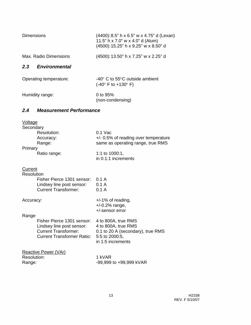
Dimensions (4400): 8.5” h x 6.5” w x 4.75” d (Lexan)
11.5” h x 7.0” w x 4.0” d (Alum) (4500): 15.25” h x 9.25” w x 8.50” d
Max. Radio Dimensions (4500): 13.50” h x 7.25” w x 2.25” d
2.3 Environmental Operating temperature: -40° C to 55°C outside ambient
(-40° F to +130° F) Humidity range: 0 to 95%
(non-condensing)
2.4 Measurement Performance Voltage Secondary
Resolution: 0.1 Vac Accuracy: +/- 0.5% of reading over temperature Range: same as operating range, true RMS
Primary Ratio range: 1:1 to 1000:1,
in 0.1:1 increments Current Resolution
Fisher Pierce 1301 sensor: 0.1 A Lindsey line post sensor: 0.1 A Current Transformer: 0.1 A
Accuracy: +/-1% of reading,
+/-0.2% range, +/-sensor error
Range Fisher Pierce 1301 sensor: 4 to 800A, true RMS Lindsey line post sensor: 4 to 800A, true RMS Current Transformer: 0.1 to 20 A (secondary), true RMS Current Transformer Ratio: 5:5 to 2000:5,
in 1:5 increments Reactive Power (VAr) Resolution: 1 kVAR Range: -99,999 to +99,999 kVAR

14 H2338 REV. F 5/10/07
Temperature Resolution: 1° F (1° C) Accuracy: +/- 2° F (1.0° C) typical; +/- 4° F (2° C) max. Range: -40° C to +60° C
(-40° F to +140° F) Time Clock Resolution: 1 second Accuracy: +/- 10 minutes per year Range: 24 hour clock Settings: 1 minute increments Phase Angle Resolution: 0.1° Accuracy: +/- 1° Range: 0° - 359° Neutral Current Resolution
Fisher Pierce AT929 sensor: 0.1 A Current Transformer: 0.1 A (secondary)
Accuracy: +/- 1% of reading, +/- 0.2% range, +/- sensor error
Range Fisher Pierce AT929 sensor: 1 to 60A Current Transformer: 0.1 to 20 A (secondary) Current Transformer Ratio: 5:5 to 2000:5,
in 1:5 increments
2.5 Input Data Log Storage Memory Size: 32 kB (standard),
128 kB (option) Memory Type: battery backed RAM for data logs and time non-volatile RAM (NVRAM) for configuration setup

15 H2338 REV. F 5/10/07
Section 3
AutoCap Functions and Operation The AutoCap provides an extensive array of programmable functions, which provide capability beyond switched capacitor control. The many protective, recording, and adaptive functions available offer an extra dimension to the AutoCap. All functions are described in this section to familiarize the user with capabilities and operation. The SmartSet software described in section 5 allows the user to select these functions as desired and program the AutoCap controller.
3.1 Primary and Override Control Functions The capacitor controller is designed to offer two levels of control; primary control mode and override control mode if desired. This allows the AutoCap to provide capacitor control based on two different parameters, in addition, up to four seasons (blocks of time) can be defined with each season having its own primary and override control mode. The AutoCap is a multifunction control providing a menu of nine available primary control modes and five override modes.
Primary Control Modes Override Control Modes
• Adaptive Var • Voltage • Var • Time • Voltage • High Temp • Current • Low Temp • Time • SCADA • High Temp • Low Temp • SCADA • No Operations
3.1.1 Primary Control Mode Operation Figure 3.1 Typical Primary Control Mode Operation exemplifies how the controller typically operates when using a primary control mode only (except Time control). The Close setpoint and Trip setpoint are values that, when reached and/or exceeded by the primary control parameter for an amount of time equal to the switching time delay, will cause a Close or Trip switching operation to occur. For example: let Figure 3.1 represent a voltage primary control mode with a Close (low voltage) setpoint of 116 Vac, a Trip (high voltage) setpoint of 124 Vac and a switching time delay of 15 s. As the voltage begins to sag, it goes below 116 V briefly, then goes back up, only causing a close operation when staying below 116 V for a length of time at least equal to the switching time delay of 15 s. The vice versa occurs for a trip operation.

16 H2338 REV. F 5/10/07
The switching time delay prevents bank switching on transient conditions. A switching time delay is not applicable to Time control based operation.
Close Setpoint
Trip Setpoint
Time
SwitchingTime Delay
CloseOperation
SwitchingTime Delay
TripOperation
Bandwidth
Figure 3.1 Typical Primary Control Mode Operation
3.1.1.1 VAr Control VAr control mode operation switches the capacitor bank based on measured line reactive power (VAr). The AutoCap senses VArs by measuring the average of the instantaneous voltage times the quadrature current component. Three-phase kVAr is calculated from the single-phase inputs by assuming balanced phase loading and the defined transformer/sensor ratios. VAr control provides the most effective capacitor switching method when energy loss reduction, demand reduction and power factor correction are important goals. VAr control with voltage override (described later) provides these VAr management benefits as well as voltage regulation. Adaptive VAr operation is described in section 3.2.1. Recommended VAr switching setpoints can be calculated as described in Figure 3.2. These setpoints are a general rule-of-thumb, and may not be appropriate for some situations. Close setpoint: 2/3 x capacitor bank size (in kVAr), lagging (+). Trip setpoint: Close set point - (1.25 x bank size), will be (-) = leading. Example Assuming a 600 kVAr bank application: Close setpoint: 2/3 x 600 kVAr = +400 kVAr (lagging) Trip setpoint: 400 kVAr - (1.25 x 600 kVAr) = -350 kVAr (leading)
Figure 3.2 Recommended VAr Switching Setpoint Calculation
Application Notes: • When using VAr control mode, the current sensor should be located on the source
(substation) side of the cap bank so the controller can detect actual change in line kVAr due to bank switching. Correct sensor installation and polarity is important to maintain proper phase angle relationship between current and voltage.

17 H2338 REV. F 5/10/07
• When more than one switched capacitor bank using VAr control is located on the same feeder, it is recommended that the controller located furthest away from the substation be set with a shorter VAr switching time delay than those closer to the substation. This will help prevent potential interaction (hunting) between controllers, and optimize line loss reduction.
• PT and Current Sensor Phase Relationships as interpreted by SmartSet software.
For the controller to work correctly and make correct calculations, the actual phase placement of the current sensor in your system must match the setup information in SmartSet software.
CASE 1. WYE Systems. For a PT wired Line to Neutral, SmartSet software assumes the PT is connected to Phase A, regardless of the way you may actually designate the phases. Please note that since the PT phase connections are not labeled in SmartSet software, there is no way for the controller to know how your phases are actually labeled. As a result:
• If the current sensor is connected to the same phase as the PT, always select Phase A as the current sensor phase.
• If the current sensor phase is 120 electrical degrees from the PT phase, select Phase B. (Assuming ABC rotation. For CBA rotation, you would select Phase C.)
• If the current sensor phase is 240 electrical degrees from the PT phase, select Phase C. (Assuming ABC rotation. For CBA rotation, you would select Phase B. )
Defined as Phase A by SmartSet software
PT
ABC
If CS here, select Phase B in SmartSet software
If CS here, select Phase C in SmartSet software
Neutral
Figure 3.2.1

18 H2338 REV. F 5/10/07
CASE 2. Delta systems. For a PT wired Line to Line, SmartSet software assumes the PT is connected to Phases B and C, regardless of the way you may actually designate the phases. Please note that since the PT phase connections are not labeled in SmartSet software, there is no way for the controller to know how your phases are actually labeled. As a result:
• If the Current Sensor is connected to the phase with no PT connections, that is defined as
Phase A by SmartSet software. • If the current sensor phase is 120 electrical degrees from the SmartSet defined Phase A,
select Phase B. (Assuming ABC rotation. For CBA rotation, you would select Phase C.) • If the current sensor phase is 240 electrical degrees from the SmartSet defined Phase A,
select Phase C. (Assuming ABC rotation. For CBA rotation, you would select Phase B.)
PT
For ABC
Phase A
Phase C
Phase B
Figure 3.2.2
SmartSet Defines Phases as:
19 H2338 REV. F 5/10/07
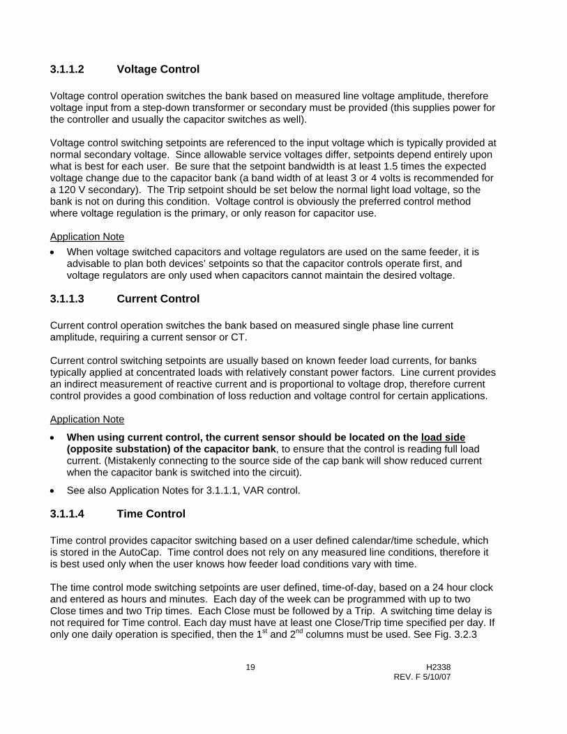
3.1.1.2 Voltage Control Voltage control operation switches the bank based on measured line voltage amplitude, therefore voltage input from a step-down transformer or secondary must be provided (this supplies power for the controller and usually the capacitor switches as well). Voltage control switching setpoints are referenced to the input voltage which is typically provided at normal secondary voltage. Since allowable service voltages differ, setpoints depend entirely upon what is best for each user. Be sure that the setpoint bandwidth is at least 1.5 times the expected voltage change due to the capacitor bank (a band width of at least 3 or 4 volts is recommended for a 120 V secondary). The Trip setpoint should be set below the normal light load voltage, so the bank is not on during this condition. Voltage control is obviously the preferred control method where voltage regulation is the primary, or only reason for capacitor use. Application Note • When voltage switched capacitors and voltage regulators are used on the same feeder, it is
advisable to plan both devices’ setpoints so that the capacitor controls operate first, and voltage regulators are only used when capacitors cannot maintain the desired voltage.
3.1.1.3 Current Control Current control operation switches the bank based on measured single phase line current amplitude, requiring a current sensor or CT. Current control switching setpoints are usually based on known feeder load currents, for banks typically applied at concentrated loads with relatively constant power factors. Line current provides an indirect measurement of reactive current and is proportional to voltage drop, therefore current control provides a good combination of loss reduction and voltage control for certain applications. Application Note
• When using current control, the current sensor should be located on the load side (opposite substation) of the capacitor bank, to ensure that the control is reading full load current. (Mistakenly connecting to the source side of the cap bank will show reduced current when the capacitor bank is switched into the circuit).
• See also Application Notes for 3.1.1.1, VAR control.
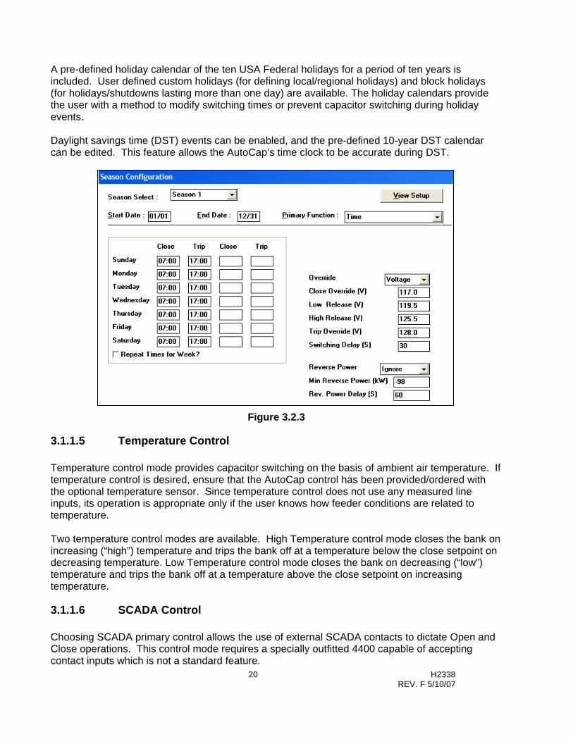
3.1.1.4 Time Control Time control provides capacitor switching based on a user defined calendar/time schedule, which is stored in the AutoCap. Time control does not rely on any measured line conditions, therefore it is best used only when the user knows how feeder load conditions vary with time. The time control mode switching setpoints are user defined, time-of-day, based on a 24 hour clock and entered as hours and minutes. Each day of the week can be programmed with up to two Close times and two Trip times. Each Close must be followed by a Trip. A switching time delay is not required for Time control. Each day must have at least one Close/Trip time specified per day. If only one daily operation is specified, then the 1st and 2nd columns must be used. See Fig. 3.2.3
20 H2338 REV. F 5/10/07
A pre-defined holiday calendar of the ten USA Federal holidays for a period of ten years is included. User defined custom holidays (for defining local/regional holidays) and block holidays (for holidays/shutdowns lasting more than one day) are available. The holiday calendars provide the user with a method to modify switching times or prevent capacitor switching during holiday events. Daylight savings time (DST) events can be enabled, and the pre-defined 10-year DST calendar can be edited. This feature allows the AutoCap’s time clock to be accurate during DST.
Figure 3.2.3
3.1.1.5 Temperature Control Temperature control mode provides capacitor switching on the basis of ambient air temperature. If temperature control is desired, ensure that the AutoCap control has been provided/ordered with the optional temperature sensor. Since temperature control does not use any measured line inputs, its operation is appropriate only if the user knows how feeder conditions are related to temperature. Two temperature control modes are available. High Temperature control mode closes the bank on increasing (“high”) temperature and trips the bank off at a temperature below the close setpoint on decreasing temperature. Low Temperature control mode closes the bank on decreasing (“low”) temperature and trips the bank off at a temperature above the close setpoint on increasing temperature.
3.1.1.6 SCADA Control Choosing SCADA primary control allows the use of external SCADA contacts to dictate Open and Close operations. This control mode requires a specially outfitted 4400 capable of accepting contact inputs which is not a standard feature.

21 H2338 REV. F 5/10/07
3.1.1.7 No-Op (No Operation) Electing No-Op, prevents any primary or override control functions. This mode can be used if using the capacitor control as a recording device only or when a control season requires no bank operations.
3.1.2 Override Control Mode Operation Figure 3.2 Typical Override Control Mode Operation exemplifies how the controller operates when using both a primary control mode and override control mode (except Time override control). If an override mode is selected, the controller will now monitor this second parameter. The controller will operate the bank based on the override control mode whenever the override parameter value reaches and/or exceeds the override close or trip setpoints for an amount of time at least equal to the override switching time delay. When the override parameter value falls back within a second set of setpoints, called release setpoints, the controller reverts back to the primary control mode. For example: let Figure 3.3 represent a VAr primary control mode with voltage override control mode. Assume voltage override Close/Trip setpoints of 113 V/127 V, voltage override release setpoints of 116V and 124V, and voltage override switching time delay of 15 s. The controller normally operates in VAr control mode but a voltage rise above 127 V (for at least 15 s) causes the control to override VAr control and perform a Trip operation based on the voltage override Trip setpoint. Immediately the voltage sags, but stays above the release setpoint of 124 V. When the voltage finally dips below 124 V for a period of at least 15 s, the controller reverts back to VAr control mode. The vice versa occurs for an override Close operation. The release setpoints along with the override setpoints form deadbands to ensure that the controller does not switch repeatedly back and forth between override and primary control modes and cause excessive bank switching (as capacitor banks can cause a secondary voltage change of 3 or more volts).
Time
Override Trip Setpoint
Override Close Release Setpoint
Override Trip Release Setpoint
Override Close Setpoint
OverrideStarts
Override TripOperation
Revert toPrimaryMode
Primary Mode
Deadband
Deadband
Override Mode
Override Mode
SwitchingTimeDelay
Figure 3.3 Typical Override Control Mode Operation

22 H2338 REV. F 5/10/07
3.1.2.1 Voltage Override When using voltage override control, the AutoCap constantly monitors voltage and overrides primary control when the voltage exceeds either the voltage override Close or Trip setpoint. Control reverts to the primary control mode when voltage retreats within the voltage override release setpoints. All setpoints utilize a selected time delay. Voltage override is very useful whenever voltage regulation is desired.
The difference between the voltage override switching setpoints and voltage override release setpoints should be at least the anticipated voltage change due to capacitor switching.
3.1.2.2 Time Override This mode provides override control based on a user defined time/calendar schedule. The time override setpoints enable a Close or Trip operation at a specified time and release back to primary control at a specified time. There is no time delay.
3.1.2.3 Temperature Override There are two Temperature Override control modes; High and Low temperature override.
High temperature override will Close the bank on increasing temperature that reaches or exceeds the user defined high temperature override set-point. Control reverts to primary mode on decreasing temperature that falls below the high temperature override release set-point. High Temperature override will also Trip the bank on decreasing temperature that reaches or exceeds the user defined low temperature override set-point. Control will revert to primary mode on increasing temperature that rises above the low temperature release set-point.
Low temperature override functions in the reverse manner. The bank will close on decreasing temperature that reaches or exceeds the user defined low temperature override set-point. Control reverts to primary mode on increasing temperature that rises above the low temperature override release set-point. Low Temperature override will also Trip the bank on increasing temperature that reaches or exceeds the user defined high temperature override set-point. Control will revert to primary mode on decreasing temperature that falls below the high temperature release set-point. All set-points utilize a time delay.
Override Mode
Override Mode
Primary Mode
Override Close Set-point = 90
Override Trip Set-point = 70
Hi Release Set-point = 85
Lo Release Set-point = 75
Deadband
Deadband
Hi Temp Override Typical Release Points
Override Close Operation
Override Trip Operation
Revert to Primary Mode
Note: Time delays not shown for clarity.
Temperature vs. Time

23 H2338 REV. F 5/10/07
3.1.2.4 SCADA Override SCADA override allows the use of external contact inputs to override local primary and override control operations. This override control mode requires a specially outfitted 4400 capable of accepting contact inputs which is not a standard feature.
3.1.3 Season / Dates The AutoCap can be programmed to operate in up to four different seasons, with each season having its own control mode. A season is a user defined block of time, each with a start date and end date specified by month and day. This enables the user to change the primary and/or override control mode and/or control setpoints based on time of year; useful if there are distinct changes in feeder conditions throughout the year. Seasons must be defined in contiguous order and the seasons must define a full year. Seasons can start on any day, as long as the season ends on the day preceding the start of the next season. For example, a three season control may be defined as:
Season 1: May 1 to Sept. 30 VAr control Season 2: Oct. 1 to Jan. 31 Voltage control Season 3: Feb.1 to April 30 No-Op
If a seasonal control scheme is not desired, configure the AutoCap as a single season control with Season 1 starting Jan. 1 and ending Dec. 31.
3.2 Adaptive Control Functions The AutoCap contains three adaptive control functions; Adaptive VAr control, PhaseFindTM and Adaptive Voltage GuardTM. All are designed to ease controller programming, simplify controller and current sensor installation and optimize control operation. Each adaptive function is user selectable; they do not have to be used if so desired. Start Adaptive Test: To activate the Adaptive Tests, make the proper selections in SmartSet setup software and “Start” the adaptive tests while the computer is connected to the controller. See Section 5.3.6 for more information on how to select and start the Adaptive Test via the SmartSet software, or see Appendix B for information on how to start the Adaptive Test using the optional Panel Set programming function.
3.2.1 PhaseFind The PhaseFind function automatically determines the proper phase angle relationship between the line current and the line voltage. A correct phase angle relationship is required for proper controller operation in VAr or Adaptive VAr control mode and for Var, W and PF data logging. In addition, PhaseFind detects reversed wiring (polarity) of the current sensor, CT or PT and automatically corrects this condition. PhaseFind operation consists of an automatic adaptive test routine which is started using SmartSet Setup program. The PhaseFind adaptive test measures line current and line voltage inputs, and adds a phase correction angle to the current signal until it is in phase with the voltage signal within a predefined limit. The correction angle compensates for phase rotation allowing the

24 H2338 REV. F 5/10/07
user to install the current sensor or CT on a different phase than the step-down transformer (VT or PT). The type of current sensor being used, and applicable PT wiring configuration (line-to-neutral or line-to-line) must be selected, so that a proper phase offset angle can be applied by the AutoCap. The phase offset angle compensates for phase offset due to the type of current sensor and wiring configuration. If the current sensor or CT input signal is detected as having reverse polarity (current signal 180° out of phase) due to the sensor wires being reversed at installation, the PhaseFind function will automatically correct this condition as part of the phase correction angle. Please Note: During the PhaseFind adaptive test, test criteria are used to ensure that angle measurement is possible and that measurements are reliable. The PhaseFind test period is 20 minutes maximum and will occur before the adaptive VAr test if both are selected. Measured inputs will not meet test criteria if the line is continuously very lightly loaded and/or very leading or if a reverse power condition is present. If test criteria are not met, the PhaseFind function will not be able to establish a correction angle and the AutoCap will not be able to calculate a VAr measurement. If this occurs and the AutoCap is programmed in Adaptive VAr or VAr control mode, the AutoCap will revert to Backup Voltage Control (if selected), or perform no control functions and operate only as a data recorder. Refer to Section 5.3.6.3 for information on clearing the adaptive test sequence and manually entering in appropriate values when the adaptive test does not successfully complete.
3.2.2 Adaptive VAr Control Description Use of Adaptive VAr control mode eliminates user programming of VAr control switching setpoints by letting the AutoCap controller automatically define optimum VAr switching setpoints. In Adaptive VAr control mode, the AutoCap controller automatically measures the size of the capacitor bank and establishes optimum VAr Trip/Close setpoints. Adaptive VAr operation consists of an automatic adaptive test period which occurs during initial start-up and/or when selected. The adaptive VAr test routine switches the capacitor bank and determines the size of the bank by measuring the difference in line kVAr when the bank is tripped and when it is closed. It then establishes VAr switching setpoints as described in Figure 3.2 in Section 3.1.1.1. Upon establishing VAr switching setpoints, the adaptive VAr function is complete and the AutoCap then functions as a conventional VAr switching controller. Please Note: During adaptive test, test criteria are used to ensure that bank measurement is possible and that measurements are reliable. The adaptive test period is completed within 20 minutes. Test criteria will not be met if the line is continuously very lightly loaded, if the current sensor is installed on the wrong side (load side) of the capacitor bank, if a reverse power condition is present or if the bank is not operating. If test criteria are not met, the Adaptive VAr function will not be able to establish VAr switching setpoints. If this occurs, the AutoCap will revert to Backup Voltage Control (if enabled ) or perform no control functions and operate only as a data recorder. Refer to Section 5.3.6.3 for information on clearing the adaptive test sequence and manually entering in appropriate values when the adaptive test does not successfully complete.

25 H2338 REV. F 5/10/07
3.2.3 Adaptive Voltage Guard Description Adaptive Voltage Guard (also called voltage restraint) is used to inhibit (prevent) capacitor switching if a switch operation (Trip or Close) will cause the line voltage to exceed user defined limits. This function prevents out of range line voltage conditions due to capacitor bank switching. Adaptive Voltage Guard operation consists of an adaptive test that measures voltage change resulting from capacitor switching obtained during the test period. The voltage change (delta V) is applied to the measured line voltage during control operation and switching is inhibited if the voltage is predicted to exceed user selected upper or lower voltage limits. The voltage guard function also allows the user to enter the delta voltage value if so desired, bypassing the adaptive function. Figure 3. 4 illustrates Voltage Guard operation. The AutoCap monitors voltage and applies the voltage change (delta V) at all times. When the capacitor bank is off-line (bank and controller in Trip condition), the Voltage Guard function prevents a close operation when line voltage is predicted to exceed the user-defined voltage upper limit. Conversely, when the capacitor bank is on-line (bank and controller in Close condition), Voltage Guard inhibits a trip operation when line voltage is predicted to fall below the user-defined voltage lower limit.
Voltage GuardInhibits Close
Delta V
Voltage GuardInhibits Trip
Voltage Upper Limit
Voltage Lower Limit
Bank in TripCondition
Bank in CloseCondition
Figure 3. 4 Voltage Guard
Please Note: During the Adaptive Voltage Guard adaptive test, test criteria are used to ensure that voltage measurement is possible and that measurements are reliable. The voltage guard adaptive test is completed within 20 minutes. Measured inputs will not meet test criteria if the line is extremely “stiff” (very small voltage change due to capacitor switching), if the voltage change varies widely between measurements or if the bank is inoperative (no measured voltage change). If test criteria are not met, the Voltage Guard feature will not be activated. Refer to Section 5.3.6.3 for information on clearing the adaptive test sequence and manually entering in appropriate values when the adaptive test does not successfully complete.
26 H2338 REV. F 5/10/07
3.3 Additional Control Functions In addition to the primary and override control modes above, three voltage bias control modes and six reverse power control modes are available.
Voltage Bias By Reverse Power • Time • Ignore • High Temp • Voltage • Low Temp • Var • Inhibit • Trip and Inhibit • Close and Inhibit
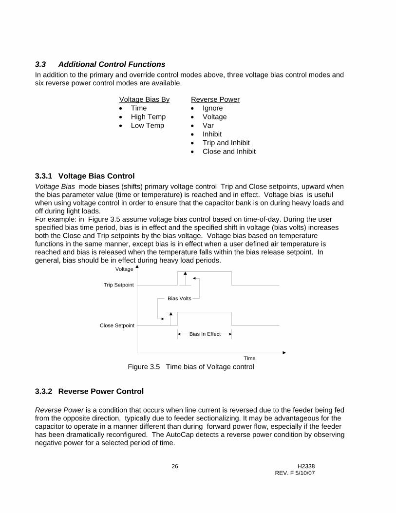
3.3.1 Voltage Bias Control Voltage Bias mode biases (shifts) primary voltage control Trip and Close setpoints, upward when the bias parameter value (time or temperature) is reached and in effect. Voltage bias is useful when using voltage control in order to ensure that the capacitor bank is on during heavy loads and off during light loads. For example: in Figure 3.5 assume voltage bias control based on time-of-day. During the user specified bias time period, bias is in effect and the specified shift in voltage (bias volts) increases both the Close and Trip setpoints by the bias voltage. Voltage bias based on temperature functions in the same manner, except bias is in effect when a user defined air temperature is reached and bias is released when the temperature falls within the bias release setpoint. In general, bias should be in effect during heavy load periods.
Trip Setpoint
Bias In Effect
Bias Volts
Close Setpoint
Time
Voltage
Figure 3.5 Time bias of Voltage control
3.3.2 Reverse Power Control Reverse Power is a condition that occurs when line current is reversed due to the feeder being fed from the opposite direction, typically due to feeder sectionalizing. It may be advantageous for the capacitor to operate in a manner different than during forward power flow, especially if the feeder has been dramatically reconfigured. The AutoCap detects a reverse power condition by observing negative power for a selected period of time.

27 H2338 REV. F 5/10/07
During a reverse power condition, a capacitor control in VAr control mode may operate the bank in a non-optimum manner. This is due to the current phase signal being reversed, preventing the control from measuring VAr accurately. In addition, since the current sensor or CT is now on the load side of the bank during reverse power, the capacitor control is unable to measure VAr change due to capacitor switching. The AutoCap includes a reverse power VAr control mode which overcomes these problems for reliable Var controlled switching during reverse power by automatically calculating modified Var Close and Trip setpoints for use during this period. When a reverse power condition is detected, the AutoCap will revert to one of the available Reverse Power control modes only after a user defined minimum reverse power kW level is reached for a specified time delay. This prevents Reverse Power control mode operation on transient (high backfeed) conditions or during times of extremely light load. • Ignore mode: Controller operates in “normal” control mode as if reverse power condition were
not present. For example: voltage, time or temperature control seasons. • Voltage mode: Controller reverts to backup voltage control mode. • VAr mode: This mode provides reliable VAr control operation by automatically calculating VAr
setpoints for use in a reverse power condition and accounting for the effect of the capacitor bank. When reverse power mode has ended, VAr control switching setpoints will return to previous normal setpoints.
• Inhibit mode: This mode maintains the bank’s last switch position and prevents any switching during reverse power.
• Trip and Inhibit: This mode will trip the capacitor bank off line upon recognition of reverse power and inhibit further capacitor switching during the reverse power condition.
• Close and Inhibit: This mode will close the capacitor bank on line upon recognition of reverse power and inhibit further capacitor switching during the reverse power condition.
When the reverse power condition has ended, the AutoCap will automatically revert to normal primary/override control mode. This happens after the user defined reverse power time delay has expired. Recording and protective function operations remain unchanged during reverse power periods.
3.4 Protective Functions In addition to control functions, several protective functions are available in AutoCap.
Protective Functions • Reversed Trip/Close Detection • Anti-Hunt • Undervoltage Inhibit • Daily close count limit • Neutral current lockout • Power up trip • Auxiliary high voltage

28 H2338 REV. F 5/10/07
3.4.1 Reversed Trip/Close Detection Please Note: This function occurs during the Adaptive Var test and is therefore available only if the adaptive Var function is selected. If the Trip and Close output wiring to the capacitor switch is reversed at installation, the capacitor bank will operate in the opposite manner to what is desired, e.g. a Close operation at the controller will result in the bank to Trip off line. This is a serious and potentially dangerous condition. The AutoCap’s reversed Trip/Close detection function detects a reversed Trip/Close wiring condition by measuring the change in line VAr due to bank switching and determines if the resulting VAr change is opposite of what is expected. Immediately upon detection, the bank is tripped by the AutoCap and all further switching operations are prevented until the wiring is corrected and the condition is cleared.
3.4.2 Anti-Hunt Rapidly cycling loads or interaction between multiple switched capacitor banks or voltage regulators located on the same feeder can cause excessive bank switching. This is termed a hunting condition and is not desirable for equipment life and power quality reasons. The Anti-Hunt function measures the time between each Close and Trip operation; if this period is shorter than the user programmed limit, a user programmed time delay is added to the Trip-to-Close period. The Anti-Hunt function is additive so that every detected hunting condition will result in adding the Trip-to-Close time delay to the previous time delay until the hunting condition is cleared. Since an abnormal condition could leave the controller in an almost unusable state, the added Trip-to-Close delay is automatically reset every seven days. For example: assume the Anti-Hunt function is selected and programmed with a minimum Close/Trip time period of 40 minutes and a close inhibit time of 60 minutes. If a Trip operation were to follow a Close operation within 40 minutes, a 60 minute time delay would be initiated during which a Close operation would not be allowed. The next Close/Trip time is then measured and if it once again occurs within 40 minutes, a 60 minute time delay is added resulting in a 120 minute time period during which a Close operation would not be allowed. This will occur every instance that the following measured Close/Trip interval falls within 40 minutes.
3.4.3 Undervoltage Inhibit The AutoCap controller is rated to operate down to 95V power input. Some capacitor switches may be damaged if switching is attempted at low voltages. The Undervoltage Inhibit function can be selected to prevent output relay operation at or below a user programmed low voltage limit.
3.4.4 Daily Close Count Limit As discussed in Section 3.4.2, it is generally not desirable to have a large number of capacitor switching operations per day. The Daily Close Count Limit function allows the user to program a maximum number of Close operations to occur in any one day. Once the limit has been reached,
29 H2338 REV. F 5/10/07
further Close operations are prevented for the remainder of the day. The daily Close count is then automatically reset at each midnight.
3.4.5 Neutral Current Lockout If a capacitor bank fuse opens on one or two phases due to a capacitor can failure or other or if a capacitor phase switch is inoperative, a current will result in the capacitor neutral lead of wye banks. If the AutoCap controller is selected with the Neutral Current sensing option, this unbalance current can be sensed by a Fisher Pierce AT929 slip core current sensor or CT, in the case of grounded wye connected banks. Also by a potential sensing device in the case of ungrounded wye connected banks. The capacitor neutral current is then constantly monitored. If it exceeds the user programmed neutral current limit, a user programmed time delay is initiated to allow the capacitor fuse to clear before the bank is tripped so that the failed bank phase can be identified. The bank is tripped off-line and then re-closed after a programmed time period. If the bank does not stay closed a lockout condition will exist until manually cleared. A bright red external LED on the bottom surface of the controller enclosure indicates this neutral current lockout condition. Manual reset by means of an externally mounted weatherproof switch, also located on the bottom of the enclosure, is required to reset the controller and resume control functions. Application Note • It is recommended that the neutral current trip setting be one-half the single phase capacitor
current. For a wye-connected bank, the setting would be equal to = .5(kVAr)/kVL-L/√3.
3.4.6 Power-Up Trip When selected, this function will trip the bank off-line within 30 seconds of power restoration. After the bank is tripped and the controller is calling for an automatic operation (example: Var close), the controller will close the bank after the set point time delay.
3.4.7 Auxiliary High Voltage Trip If the line voltage exceeds the programmable Auxiliary High Voltage Trip setpoint, the controller will trip the bank off-line within the programmable time delay. The function is completely separate from any of the other voltage control modes and is intended for use as a safe guard against abnormally high voltage conditions, which require a faster response than the voltage override. Voltage override and Auxiliary High Voltage Trip can be used at the same time. Auxiliary High Voltage is always set higher than Voltage Override.
3.5 Recording Functions In addition to capacitor bank control and protective functions, the AutoCap offers extensive data recording capability. Recorded data provides a means to analyze feeder conditions and controller/bank operation. User selectable load data and operations recording capability are summarized below.
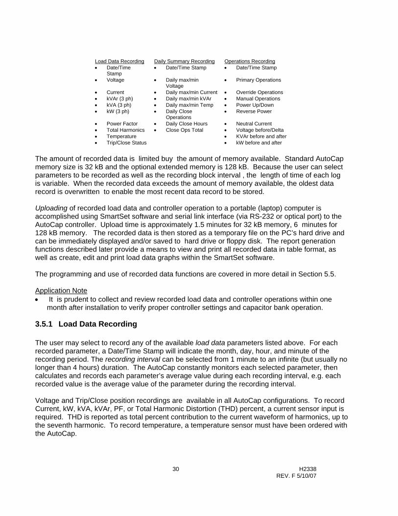
30 H2338 REV. F 5/10/07
Load Data Recording Daily Summary Recording Operations Recording • Date/Time
Stamp • Date/Time Stamp • Date/Time Stamp
• Voltage • Daily max/min Voltage
• Primary Operations
• Current • Daily max/min Current • Override Operations • kVAr (3 ph) • Daily max/min kVAr • Manual Operations • kVA (3 ph) • Daily max/min Temp • Power Up/Down • kW (3 ph) • Daily Close
Operations • Reverse Power
• Power Factor • Daily Close Hours • Neutral Current • Total Harmonics • Close Ops Total • Voltage before/Delta • Temperature • KVAr before and after • Trip/Close Status • kW before and after
The amount of recorded data is limited buy the amount of memory available. Standard AutoCap memory size is 32 kB and the optional extended memory is 128 kB. Because the user can select parameters to be recorded as well as the recording block interval , the length of time of each log is variable. When the recorded data exceeds the amount of memory available, the oldest data record is overwritten to enable the most recent data record to be stored. Uploading of recorded load data and controller operation to a portable (laptop) computer is accomplished using SmartSet software and serial link interface (via RS-232 or optical port) to the AutoCap controller. Upload time is approximately 1.5 minutes for 32 kB memory, 6 minutes for 128 kB memory. The recorded data is then stored as a temporary file on the PC’s hard drive and can be immediately displayed and/or saved to hard drive or floppy disk. The report generation functions described later provide a means to view and print all recorded data in table format, as well as create, edit and print load data graphs within the SmartSet software. The programming and use of recorded data functions are covered in more detail in Section 5.5. Application Note • It is prudent to collect and review recorded load data and controller operations within one
month after installation to verify proper controller settings and capacitor bank operation.
3.5.1 Load Data Recording The user may select to record any of the available load data parameters listed above. For each recorded parameter, a Date/Time Stamp will indicate the month, day, hour, and minute of the recording period. The recording interval can be selected from 1 minute to an infinite (but usually no longer than 4 hours) duration. The AutoCap constantly monitors each selected parameter, then calculates and records each parameter’s average value during each recording interval, e.g. each recorded value is the average value of the parameter during the recording interval. Voltage and Trip/Close position recordings are available in all AutoCap configurations. To record Current, kW, kVA, kVAr, PF, or Total Harmonic Distortion (THD) percent, a current sensor input is required. THD is reported as total percent contribution to the current waveform of harmonics, up to the seventh harmonic. To record temperature, a temperature sensor must have been ordered with the AutoCap.
31 H2338 REV. F 5/10/07
Voltage transformer and current transformer values must have been entered into the AutoCap setup for SmartSet to calculate the primary values. kW, kVA and kVAr are calculated as three phase values by assuming balanced phase loading.
3.5.2 Daily Summary Log The Daily Summary Log records the maximum and minimum daily values of voltage, current, kVAr, temperature and time stamps the hour and minute when they occurred. The number of Close operations each day and number of hours in the Close position each day are recorded. In addition, the total Close operations Since the log configuration was initialized is recorded.
3.5.3 Events Log The Events Log stores each Trip and Close operation and the associated control mode which caused the operation to occur. The change in voltage due to each Trip and Close operation is provided by recording the voltage before switching and the change in voltage due to switching. Similarly, kVAr and kW values before and after switching are recorded (AutoCap with line current input only). Power up / power down events are recorded following power losses which have a duration of at least 50 ms . A date/time stamp is provided for all recorded operations/events.
3.6 Monitoring/Operating Functions The Monitoring/Operating function allows the user to locally interrogate the AutoCap controller with a portable computer running SmartSet software and a serial link interface (via RS-232 or optional optical port) to the AutoCap controller. Real-time monitoring of line conditions and controller status are displayed on one screen for quick and easy analysis. In addition, Trip and Close operations can also be performed from the computer if desired. Use of the Monitoring/Operating functions are covered in detail in Section 5.
3.7 Report Generation Functions The Report Generation functions included in the SmartSet software provide a means to display and print all recorded data in tabular form, as well as create and print graphs from the recorded load data. Graphing edit functions allow the user to create tailored graphs within SmartSet without using a separate piece of software. Use of the Report Generation functions are covered in detail in Section 5.
3.8 Local Indications and Manual Operation The AutoCap controller panel contains toggle switches for local manual bank operation and LED’s for status indication. Fuses, test jacks and RS-232 serial port are also included on this panel, as well as the optional LCD display. These and other features are covered in detail in Section 6.

32 H2338 REV. F 5/10/07
3.9 PanelSet Front Panel Programming Functions PanelSet is intended to allow field modifications of controller programs without the need to connect a laptop computer. The controller is placed in a “Set” mode using a front panel toggle switch. The controller setup can be reviewed and or modified using the Up/Down and Advance/Enter toggles switches provided on the front panel of the controller. PanelSet can also be used to activate and start/stop the Adaptive tests. Programming Note: PanelSet only supports a single Trip/Close time event. Once the Panel Set option is utilized, only one trip and one close per day is active, disabling the second operation if programmed with SmartSet.
PanelSet Local Control SetupSet the MAN / SET / AUTO switch to SET: Momentarily press theADVANCE/ENTER switch to ADVANCE to select the setup category.Then, press ENTER to accept an entry and step to the next selection.
CLOSE INHIBIT
AC POWER
PROCESSOR OK
TRIP INHIBIT
CL
TR
REVERSE POWER
PENDINGFLASH:
MAN
AUTO
RECEIVE
TRANSMIT
RS-232COMM PORT
LOADFUSEPCC
FUSE SENSOR LOWSENSOR HIGH
NEUTRAL
R
LINE
ON:
ON:
ON:
ON:
ON:
FLASH:
CLOSE-UP
TRIP-DOWN
SET
ENTER
ADVANCE
POWERFLEXUTO AP ONTROLLERA C C
FISHER PIERCE DIVISION
Site InstallPCC ID 1232
Increments Value orSetting Displayed.
Decrements Value orSetting Displayed.
Step to Next Category
Accept Setting and Moveto Next selection withinCategory
Enable PanelSet LocalProgramming
TM
Site wiring and equipment
Various time delays andswitching inhibitscommon to all seasons
Various functionscommon to allseasons
Local controlsetup for eachseason
Start AdaptiveTest if any havebeen selected.
Site InstallPCC ID 1232
Delays / InhibitsRLY Pulse 10 Sec
Other FunctionsMax CL / Day 10
Start ADAPT TSTN
Season 101/01 Thru 12/31
SETUP CATEGORY
See Appendix B for PanelSet programming details
Note: The following functions cannot be changed using Panel Set. These changes can only be made using SmartSet.
• Date/Time • Season Dates • Data Log Configuration • Holiday Settings • Volt or VAR Bias • Power Up Trip • SCADA Override • In Timeclock mode:
o Changes for an individual day, PanelSet gives only 1 setting for 5 day weekday and 1 setting for 2 day weekend.

33 H2338 REV. F 5/10/07
3.10 Communications Option A variety of options are available to allow one- and two-way communications with the AutoCap. The 4400 series can communicate using standard modems along with SmartSet setup software. The series 4500 with DNP 3.0 protocol option and data type radio will support two-way communications.

34 H2338 REV. F 5/10/07
Section 4
SmartSet Installation and Startup
4.1 Necessary Equipment To use SmartSet software, you need: Desktop or laptop computer with following requirements:
Computer Type IBM Compatible Processor 386 or greater Operating System Windows 3.1 or later RAM 2 MB or higher Hard disk space available 1.4 MB Disk Drive 3.5 inch, 1.44 MB Monitor Monochrome, CGA, VGA, SVGA Serial Port Com 1, Com 2,
Com 3, Com 4 Baud Rate 9600 baud Serial Communications Cable Male to female, straight-through
4.2 Installing SmartSet To install from drive A or B, 1. Insert the SmartSet program disk into drive A or B 2. Start Windows, select File Manager in group Main, then choose File | Run. 3. Type A: setup (or B: setup if you are using drive B) and press <Enter>. To begin working with SmartSet double-click its icon in the SmartSet group of the Windows Program Manager.

35 H2338 REV. F 5/10/07
4.3 Connecting a PC to the AutoCap Controller
CAUTION: The AutoCap Controller may contain an internal ground-to-neutral connection. Confirm power polarity. Reversal of line and neutral wiring to the unit will connect all metal parts to line voltage. The procedure for connecting the AutoCap controller to a PC is as follows: 1. Connect the male cable 9-pin connector to the RS-232 communication port located on the
controller panel. For optical communications, use the optical port located on the side of the controller enclosure instead of the RS-232 port.
2. Connect the female cable connector to the proper serial communications port (NOT monitor port) of the PC.
3. Turn the PC on. 4. Power up the capacitor controller (if not already). Alternatively, a USB to RS-232 adapter can be used for connecting to PC’s that only have a USB port. Please note that some USB to RS-232 adapters may not provide the needed control signals required by the AutoCap Controller. In that case, please refer to Appendix D for more information on USB adapters.
!

36 H2338 REV. F 5/10/07
Section 5
SmartSet Application Software There are two basic components of the software used with the AutoCap controller:
1. Operating Software. Control algorithms and logic residing in the controller’s memory. 2. Application Software. SmartSet application software and associated files residing in PC or disk.
5.1 Overview The operating software resides within the AutoCap’s nonvolatile memory and provides operating instructions to the controller’s microprocessor. The microprocessor uses these instructions in conjunction with other inputs such as measurements (time, current, voltage, etc.) to determine proper controller. Some of the operating software is configured by the user; control mode and setpoints. This configuring is called controller programming and is accomplished by using the SmartSet application software. Some of the firmware can not be user configured, such as the operating control algorithms and logic. Changes to the control algorithms and logic usually require physical replacement of memory devices in the controller. The SmartSet application software performs three major functions: 1. Controller Programming Edit/save setup (.stp and .def) files *Download /Upload setup files 2. Controller Monitoring *Monitor real-time line conditions and controller status 3. Recorded Data Transfer and Viewing *Upload/view/save/print recorded data (.log) files Edit/view/print graphs Functions noted by * indicate that this function requires the computer to be communicating with an energized AutoCap controller. Refer to Section 4.3 for instructions on connecting the PC to the AutoCap.
5.1.1 Controller Programming The AutoCap is programmed by SmartSet setup files downloaded to the AutoCap (sent from the computer to the controller). The setup file contains the user defined control modes, setpoints, etc., which configures the controller’s operating software as described in section 5.1. The computer does not need to be connected to the controller while creating/editing/saving setup files; setup (.stp) files can be created within SmartSet and saved for future downloading into one or more controllers. The setup file stored in the controller memory can also be uploaded (retrieved from the controller to the computer) for editing or display.

37 H2338 REV. F 5/10/07
5.1.2 Default Program The AutoCap controller is programmed using a default setup file downloaded at the factory into each controller. The default setup file is also provided on the 3.5 inch SmartSet diskette as a .def file. The default program is provided as a starting point or baseline control setup to ease the user’s programming task. User customized setup files can then be created from editing the factory default setup file. The default file cannot be mistakenly deleted. Please Note: Unless otherwise arranged with Fisher Pierce, the default control program uses voltage control mode and other settings and selections as a means of providing an example program. The default program is not meant to fulfill specific user applications or requirements. DO NOT attempt to install and operate the AutoCap control without first examining, editing and programming the controllers as necessary to ensure proper operation.
5.1.3 File Definition The SmartSet software uses files for programming and data recording/report functions. Each type of file is related to a particular purpose, and is denoted by use of a three letter file extension. Figure 5.1 provides an overview of files used by SmartSet and AutoCap.
Filename
File Type Purpose
x.stp Setup File Controller Programming x.def Default Setup File Baseline Setup File x.log Log File All recorded data
Figure 5.1
Files can be saved on a PC’s hard drive (usually defined as the C: drive) or on floppy disk (usually A: or B: drive). Setup files can be manipulated only by using SmartSet software.
5.2 Using SmartSet Application Software The SmartSet application software is Windows-based for use with an IBM or equivalent PC. SmartSet is menu driven and prompted for ease of use. We recommend that you are first familiar with the functions available and their operation (as described in Section 3 and this section), before actually programming the AutoCap. Figure 5.2 provides an overview of how the SmartSet software is organized. SmartSet is organized in a “flat” hierarchy, with only three levels or layers, so that working within the program is quick and easy. Commands allow you to move within SmartSet and direct action. Screens within SmartSet group together similar functions or operations to make working in SmartSet more efficient. Please Note (On-Screen Help): • On-screen help is available which defines most commands and inputs required simply by
pressing the F1 key. The F1 key will display a prompt box explaining the use and/or meaning of the input or command currently selected. Pressing the F1 key again will turn the prompt box off.
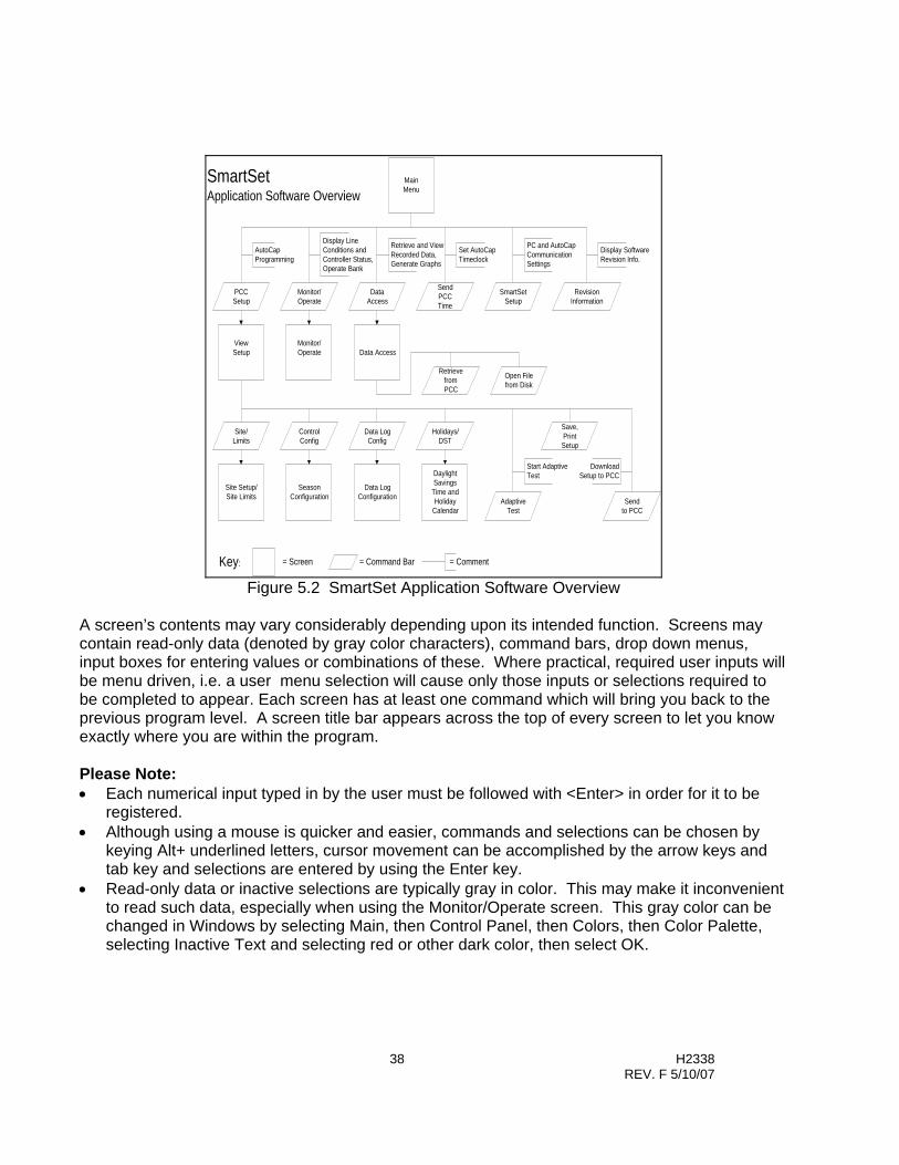
38 H2338 REV. F 5/10/07
MainMenu
ViewSetup Data Access
Monitor/Operate
Site Setup/Site Limits
SeasonConfiguration
Data LogConfiguration
DaylightSavings
Time andHoliday
Calendar
PCCSetup
Monitor/Operate
DataAccess
SendPCCTime
SmartSetSetup
RevisionInformation
Site/Limits
ControlConfig
Data LogConfig
Holidays/DST
AdaptiveTest
Save,PrintSetup
SmartSetApplication Software Overview
AutoCapProgramming
Display LineConditions andController Status,Operate Bank
Retrieve and ViewRecorded Data,Generate Graphs
Set AutoCapTimeclock
PC and AutoCapCommunicationSettings
Display SoftwareRevision Info.
Key: = Comment= Command Bar= Screen
RetrievefromPCC
Open Filefrom Disk
Sendto PCC
Start AdaptiveTest
DownloadSetup to PCC
Figure 5.2 SmartSet Application Software Overview
A screen’s contents may vary considerably depending upon its intended function. Screens may contain read-only data (denoted by gray color characters), command bars, drop down menus, input boxes for entering values or combinations of these. Where practical, required user inputs will be menu driven, i.e. a user menu selection will cause only those inputs or selections required to be completed to appear. Each screen has at least one command which will bring you back to the previous program level. A screen title bar appears across the top of every screen to let you know exactly where you are within the program. Please Note: • Each numerical input typed in by the user must be followed with <Enter> in order for it to be
registered. • Although using a mouse is quicker and easier, commands and selections can be chosen by
keying Alt+ underlined letters, cursor movement can be accomplished by the arrow keys and tab key and selections are entered by using the Enter key.
• Read-only data or inactive selections are typically gray in color. This may make it inconvenient to read such data, especially when using the Monitor/Operate screen. This gray color can be changed in Windows by selecting Main, then Control Panel, then Colors, then Color Palette, selecting Inactive Text and selecting red or other dark color, then select OK.

39 H2338 REV. F 5/10/07
5.2.1 Main Menu Screen To start SmartSet, double click on the SmartSet program icon in Windows Program Manager. The first screen to appear is the main menu. The main menu screen contains six commands plus an Exit command. Figure 5.3 lists all user tasks accomplished with SmartSet and the associated main menu command. A brief description of major functions of each main menu command and associated screen title is given under Description. In addition, the Section column defines the section in this manual where these commands/tasks are covered.
Task Command Description Section
Programming Controller
PCC Setup View Setup Screen Retrieve, View, Edit, Save, Print, and Download Setup File
5.3
Monitoring Controller Status and Line Conditions
Monitor/Operate Monitor/Operate Screen View Line Conditions Show Controller Status Verify Control Settings Remote Trip/Close
5.4
Retrieving (Uploading) Recorded Data, Report/Graphing Functions
Data Access Data Access Screen Retrieve, Display, Edit, Graph, Save, Print Recorded Data
5.5
Setting Controller Time Clock
Send PCC Time Set and Download Controller Time
5.6
Configuring Communications
SmartSet Setup Communication Setup Options
5.7
Display Revision Information
Revision Information
SmartSet revision information
Exiting SmartSet Exit Return to Windows Program Manager
Figure 5.3 Main Menu Commands
Figure 5.4 shows the Main Menu as it appears on your PC screen. The main menu displays the SmartSet revision level, and the time and date according to your PC.

40 H2338 REV. F 5/10/07
Figure 5.4 SmartSet Main Menu
5.3 PCC Setup (Controller Programming) All programming functions occur under the main menu command PCC Setup. As described in Section 5.1.1, controller programming consists of editing a setup file in your PC using SmartSet, and then downloading this file to the AutoCap. The PCC Setup command will initiate a pop out menu titled Retrieve Setup from... with up to four selections, as shown within Figure 5.4. This menu allows you to choose the setup file as described below:
PCC retrieves the setup file stored in the controller memory. The controller must be powered and connected to the PC’s serial port via RS-232 or optical port. Disk retrieves a setup (.stp) file from one of the PC’s disk drives. A pop out box will provide drop down menus so the user may select disk drive and file. Defaults from Disk is used to retrieve the factory default (.def) file, residing in the SmartSet directory in the PC’s hard drive. View Current Setup returns the user to the setup file previously retrieved and currently being edited or displayed. Only selectable after opening a setup file and returning to PCC Setup.
After selecting the setup file, the View Setup screen will appear.

41 H2338 REV. F 5/10/07
Please Note: • If you are creating a controller setup file for the first time, select the default setup. When you
are finished working with the setup file you may save it under a new file name and save it to the directory and disk drive of your choosing.
• If you are changing even just one item in a setup, it must be resaved and then downloaded into the controller for the change to take place in the controller setup.
5.3.1 View Setup Screen The View Setup screen is read-only, no user inputs are made here. The purpose of the View Setup screen is to: 1. Allow user to view major setup file parameters on one screen. 2. Furnish a means to verify a complete and accurate setup file. 3. Provide a “home base” for controller programming functions. The View Setup screen as shown in figure 5.5 includes three distinct sections. The top of the screen includes all programming commands. The mid-section contains a summary of major control parameters and season data. The bottom section is a summary of the site configuration and other important control/protective parameters. The PCC identification number (input through Site/Limits), the setup file name, and the computer’s time and date are also displayed.
Figure 5.5 View Setup Screen

42 H2338 REV. F 5/10/07
All parameters displayed on the View Setup screen are selected/input on screens accessed by using the commands on this screen. Figure 5.6 provides an overview of the each View Setup screen command, and the section number in this manual where each is covered. The order in which these commands should be used is as shown in Figure 5.6, starting from the top and working down.
Command Description Section
Site/Limits (1)
Site Setup / Site Limits Screen Current sensor type and ratio selection
PhaseFind or circuit type selection Voltage Guard selection
Anti-Hunt selection Neutral Current Lockout selection Delay and inhibit timers selection
5.3.2
Control Config (2)
Season Configuration Screen Season definition
Primary and override control mode selection
Setpoint and time delay definition Reverse power mode selection
5.3.3
Data Log Config (3)
Data Log Configuration Screen Load data log definition Operations log definition
Daily Summary log definition
5.3.4
Holidays/DST (4)
Daylight Savings Time and Holiday Calendar Screen
Daylight savings time selection Traditional holidays selection
Custom holiday definition Block holiday definition
5.3.5
Save Setup (5)
Save (and name) current setup file 5.3.7
Print Setup (6)
Print current setup file 5.3.8
Send to PCC (7)
Download current setup file to controller 5.3.9
Adaptive Test (8)
Start, stop, and disable selected Adaptive features
5.3.6
Main Menu (9)
Return to Main Menu
Figure 5.6 View Setup Commands
5.3.2 Site/Limits (Control Selections) Selecting the Site/Limits command displays the Site Limits / Site Setup screen as shown in Figure 5.7. This screen is roughly divided into three main sections; Site Installation, Time Delays/Inhibits, and Operating Limits for All Seasons. The Site Installation section contains required user selections for wiring configuration [voltage transformer connected line-to-line (usu. delta) or line-to-neutral (usu. wye)], current sensor installation, current sensor type, and current and voltage transformer ratios. Selection of the adaptive PhaseFind function is available by selecting “adaptive” for Phase Rotation, Current Sensing Phase or Current Sensing Direction. If using a Fisher Pierce 1301 sensor, automatic correction for cable diameter (outside diam. including insulation) is available. Adjustment of sensed current amplitude and angle for any current sensor type is available if required. The

43 H2338 REV. F 5/10/07
amplitude input is a divider applied to the sensed current amplitude. See also Application Notes in section 3.1.1.1 for information on selecting the correct current sensing phase. Adaptive Voltage Guard is selected by choosing Adaptive from the Volt Guard drop down menu. The user may input a voltage rise (Delta E) by choosing Programmed from the drop down menu, and inputting a voltage rise, thus bypassing the adaptive function. Meanings of all inputs are given by selecting the F1 function key for each input selected.
Figure 5.7 Site Setup / Site Limits Screen
5.3.3 Control Config (Control Mode and Season Selection) The Control Config command brings up the Season Configuration screen. This screen consists of two major sections as shown in Figure 5.8. The top portion contains season selection, season dates, and primary control mode selection. Season Dates are a user-defined block of time. This function allows for mode / setpoint changes depending upon the time of year. If one season is selected, the season must be programmed for a full year ( Start Date: 01/01 – End Date: 12/31). If two seasons are desired, the dates selected for the two seasons must add up to a full year [( Season 1: Start Date: 10/01 – End Date: 03/31) (Season2: Start Date: 04/01 – End Date: 09/30)]. The same criteria is true with the addition of three or four seasons. The bottom section includes primary control mode switching setpoint inputs, override control modes (and setpoints) and reverse power mode selection. Adaptive VAr mode and detection of reversed Trip/Close wiring is selected by clicking on appropriate selection box. Voltage bias is available if voltage is chosen as the primary control mode. Current sensor ratio and voltage transformer ratio are copied from the Site Limits screen and are therefore read- only values. SCADA Override Priority is available only with specially configured AutoCaps which include external SCADA contact inputs and allow override of both primary and override control functions

44 H2338 REV. F 5/10/07
Figure 5.8 Season Configuration Screen Please Note: • Changes made to site installation inputs within Site/Limits can effect setpoints within the
Season Configuration screen. Check control setpoints if a change has been made to site installation inputs.
• When entering data, the values may change slightly when <ENTER> is pressed. This is due to the software automatically resolving the data, relative to full scale.
• Applicable inputs and selections will vary according to which primary control mode has been selected. (Voltage bias is available only with primary voltage control).
• Reverse Trip/Close wiring detection available only when Adaptive Var primary mode is selected.
• After Season 1 has been defined, next season (season 2) is defined by selecting Season 2.
5.3.4 Data Log Config (Recorded Data Selection) Clicking on Data Log Config command displays the Data Log Configuration screen. This screen, as shown in Figure 5.9, allows the user to select recorded data parameters and has three sections reflecting each type of recorded data; Load Profile Log, Events Log and Daily Summary Log.
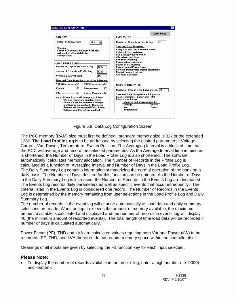
45 H2338 REV. F 5/10/07
Figure 5.9 Data Log Configuration Screen The PCC memory (RAM) size must first be defined: standard memory size is 32k or the extended 128k. The Load Profile Log is to be addressed by selecting the desired parameters : Voltage, Current, Var, Power, Temperature, Switch Position. The Averaging Interval is a block of time that the PCC will average and record the selected parameters. As the Average Interval time in minutes is shortened, the Number of Days in the Load Profile Log is also shortened. The software automatically calculates memory allocation. The Number of Records in the Profile Log is calculated as a function of Averaging Interval and Number of Days in the Load Profile Log. The Daily Summary Log contains information summarizing the normal operation of the bank on a daily basis. The Number of Days desired for this function can be entered. As the Number of Days in the Daily Summary Log is increased, the Number of Records in the Events Log are decreased. The Events Log records daily parameters as well as specific events that occur infrequently. The criteria listed in the Events Log is considered one record. The Number of Records in the Events Log is determined by the memory remaining from user selections in the Load Profile Log and Daily Summary Log. The number of records in the event log will change automatically as load data and daily summary selections are made. When an input exceeds the amount of memory available, the maximum amount available is calculated and displayed and the number of records in events log will display 40 (the minimum amount of recorded events). The total length of time load data will be recorded in number of days is calculated automatically. Power Factor (PF), THD and kVA are calculated values requiring both Var and Power (kW) to be recorded. PF, THD, and kVA therefore do not require memory space within the controller itself. Meanings of all inputs are given by selecting the F1 function key for each input selected. Please Note: • To display the number of records available in the profile log, enter a high number (i.e. 9000)
and <Enter>.

46 H2338 REV. F 5/10/07
5.3.5 Holidays / Daylight Saving Time The Holidays/DST command and associated Daylight Saving Time and Holiday Screens are used to select holiday, shutdown and daylight saving time (DST) schedules. All Holiday schedules are used to modify time based switching operation applicable only when using Time primary mode. All other control modes ignore Holidays. The DST and holiday schedules are active in the PCC for ten year’s from the selected start year. DST command displays the ten year daylight savings time schedule (“spring ahead” and “fall back” days) which can be user edited. Daylight Savings Time is automatically compensated for in accordance with the DST schedule. Traditional Holiday command displays the ten year U.S. federal holiday schedule. Holidays are de-activated by clicking on the holiday’s selection box. The holiday date appears for each year when active. Custom Holiday command displays a ten-year undefined holiday schedule which can be user defined for local/regional holidays in addition to the U.S. Traditional Holiday schedule. Block Holiday command displays a ten year undefined block holiday schedule which can be user defined to account for holidays or shutdown schedules which last for more than one day. This may be useful for industrial plant loads which may have extended shutdown periods. The Trip and Close time applicable for each date is entered in the appropriate input boxes. For no switching operations leave the Trip and Close times blank. Figure 5.10 shows the Daylight Savings Time and Holiday Calendar Screen with the Traditional Holiday Calendar schedule displayed. Meanings of all commands, selections and inputs are given by selecting the F1 function key for each input selected.
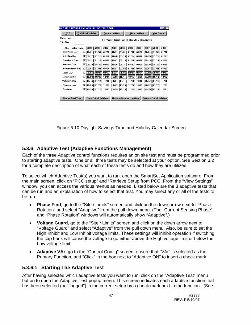
47 H2338 REV. F 5/10/07
Figure 5.10 Daylight Savings Time and Holiday Calendar Screen
5.3.6 Adaptive Test (Adaptive Functions Management) Each of the three Adaptive control functions requires an on site test and must be programmed prior to starting adaptive tests. One or all three tests may be selected at your option. See Section 3.2 for a complete description of what each of these tests do and how they are utilized. To select which Adaptive Test(s) you want to run, open the SmartSet Application software. From the main screen, click on “PCC setup” and “Retrieve Setup from PCC. From the “View Settings” window, you can access the various menus as needed. Listed below are the 3 adaptive tests that can be run and an explanation of how to select that test. You may select any or all of the tests to be run.
• Phase Find, go to the “Site / Limits” screen and click on the down arrow next to “Phase Rotation” and select “Adaptive” from the pull down menu. (The “Current Sensing Phase” and “Phase Rotation” windows will automatically show “Adaptive”.)
• Voltage Guard, go to the “Site / Limits” screen and click on the down arrow next to “Voltage Guard” and select “Adaptive” from the pull down menu. Also, be sure to set the High Inhibit and Low Inhibit voltage limits. These settings will inhibit operation if switching the cap bank will cause the voltage to go either above the High voltage limit or below the Low voltage limit.
• Adaptive VAr, go to the “Control Config” screen, ensure that “VAr” is selected as the Primary Function, and “Click” in the box next to “Adaptive ON” to insert a check mark.
5.3.6.1 Starting The Adaptive Test After having selected which adaptive tests you want to run, click on the “Adaptive Test” menu button to open the Adaptive Test popup menu. This screen indicates each adaptive function that has been selected (or “flagged”) in the current setup by a check mark next to the function. (See

48 H2338 REV. F 5/10/07
Figure 5.11) The screen has two commands, Start Test and Cancel, which are described as follows:
Start Test initiates all of the flagged adaptive functions. The controller must be powered and communicating to the computer and the active mode must be local as indicated on the monitor screen or panel display. The controller will then start the adaptive test(s), all of which begin with a Trip operation. The active mode will change to “Adaptive”. The Adaptive Angle (PhaseFind) test occurs first if more than one adaptive test is selected. Adaptive VAr and Adaptive Voltage Guard tests follow and will cause a Close operation followed by a Trip operation approximately 5 minutes later.
Figure 5.11 Adaptive Test Popup Screen The tests will be completed within 20 minutes. After completion, confirm that the Adaptive test was successful:
• Select “PCC Setup” from the SmartSet main screen and click on “Retrieve Setup from PCC”. Click on the “Adaptive Test” menu button. At the Adaptive Test pop up box, confirm that all the checkmarks have been cleared. If any checkmarks remains it means that the adaptive test for that function was unsuccessful.
Check-marked items indicate which of the 3 Adaptive Tests will be run.
NOTE: If you need to “clear” the adaptive settings due to an unsuccessful test, make sure all check boxes are cleared and then click on “Start Test”. See Section 5.3.6.3 for more information.
49 H2338 REV. F 5/10/07
If any of the adaptive tests were unsuccessful, the PCC may revert to “Backup Voltage Control”. See Section 5.3.6.3 for information on clearing the Adaptive Test sequence and manually entering in appropriate values Cancel returns the user to the View Setup screen without initiating adaptive test(s). Once the Adaptive test is started, it must complete (pass or fail) Meanings of all commands are given by selecting the F1 function key for each input selected. 5.3.6.2 Pre-Programming The Adaptive Test For Auto Start To start Adaptive Tests following controller installation without use of a computer in the field, the following steps should be followed in the lab or office while the controller is powered and communicating with a PC. The PCC must be in the active local mode as indicated on the monitor screen or panel display. 1. Program controller by downloading the complete setup with the desired adaptive functions
selected. 2. From the “View Setup Screen” select the Adaptive Test command. 3. Select “Start Test”; the Adaptive Test (s) should start. 4. As soon as the Trip relay is energized, remove power from the PCC; set the MAN/AUTO
switch to Manual. • Note that power must be removed while the Trip command is “active”. (The Trip pulse
duration has a default factory setting of 10 seconds.) 5. Assure that the AUTO/MAN switch is in MAN before installing the PCC in the field. 6. When the AUTO/MAN switch is set to AUTO, the controller will immediately start adaptive
testing without requiring connection to a computer. 5.3.6.3 If The Adaptive Test Is Unsuccessful If one or more of the Adaptive tests do not complete successfully it will be due to either an installation error or test results that were “out of range” when the capacitor bank was switched in and out.
To get an idea of what may have caused the unsuccessful adaptive test, go back to the Main Menu and click on “Data Access”. At the next menu, click on “Retrieve Logs” from PCC”. (This operation will take several minutes). When the data download finishes, click on the block next to “View Logs”. At the down arrow, select “Event Logs”. You can now review the control's Event Log to determine the reason for the unsuccessful Adaptive Test. See Appendix C for a list of error messages, causes and corrective actions.
If you are able to find and correct any setup errors you may either re-select and re-start the adaptive test again or enter the appropriate values manually in SmartSet software.
To enter the appropriate values manually, it will first be necessary to “clear” the Adaptive “flags” set in the controller. To do this:
1. Go to the main menu and retrieve the set up information from the PCC.
2. Go to the “Site / Limit” and/or “Control Config” screens and de-select the Adaptive settings.
3. After clearing all settings that still show “Adaptive”, start the Adaptive test again. (The boxes next to the 3 Adaptive Tests should be empty.) The Adaptive Test will run, clear the “flags” from memory and complete within several seconds. See Figure 5.11.

50 H2338 REV. F 5/10/07
NOTE: You CANNOT simply clear the Adaptive selections at the “Site Limits” screen and/or “Control Config” screen and then “Send to PCC”. This will NOT clear the adaptive settings. You MUST use the above procedure to clear the adaptive settings (flags).
After clearing the Adaptive “flags” you can now make changes manually and download them into the controller.
• If the “Adaptive VAr” test failed, manually enter in the Close and Trip set-points in the “Control” screen based on the size of the capacitor bank. See Section 3.1.1.1 for general recommendations on calculating these settings.
• If the “Voltage Guard” adaptive test failed, select “Programmed” from the pull down menu. Manually enter in the expected or measured change in voltage when the capacitor bank is switched in the “Site / Limit” screen. Enter also the High and Low voltage threshold levels. See section 3.2.3 for more information.
• If the “Phase Find” adaptive test failed, return to the main menu in SmartSet and select “Monitor/Operate”. Note the “Current Angle (deg)” reported. Then go to section 7.2.4 and follow the directions to manually correct for an incorrect current (phase) angle. See also Application Notes in section 3.1.1.1 for information on selecting the correct current sensing phase.
After making all desired changes, save the setup (if desired) and then from the “View Setup” menu, click on “Send To PCC” to download the settings. See section 5.3.9.
5.3.7 Save Setup Selection of the Save Setup command activates a Windows “Save As... pop up box allowing the user to name and save the setup file to a select disk drive and directory. Retain the .stp extension.
5.3.8 Print Setup The Print Setup command provides a printout of the setup on the default printer as defined in Windows.
5.3.9 Send to PCC (Program Controller) The Send to PCC command downloads the current setup file to the AutoCap, programming the controller as defined by the setup file. The AutoCap must be powered and communicating with a computer. 5.3.10 Comm Protocol (4500 Series Only) The Comm Protocol menu button is enabled only when the PCC Model 4500 is selected in the SmartSet Setup. (refer to section 5.7). Clicking on Comm Protocol will bring up the PCC Protocol Setup screen which allows configuration of many of the DNP parameters. Only users of 4500 Series controls which employ two-way communications utilizing DNP communications protocol should edit these selections.
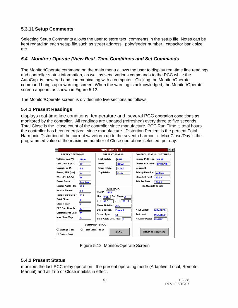
51 H2338 REV. F 5/10/07
5.3.11 Setup Comments Selecting Setup Comments allows the user to store text comments in the setup file. Notes can be kept regarding each setup file such as street address, pole/feeder number, capacitor bank size, etc.
5.4 Monitor / Operate (View Real -Time Conditions and Set Commands The Monitor/Operate command on the main menu allows the user to display real-time line readings and controller status information, as well as send various commands to the PCC while the AutoCap is powered and communicating with a computer. Clicking the Monitor/Operate command brings up a warning screen. When the warning is acknowledged, the Monitor/Operate screen appears as shown in Figure 5.12. The Monitor/Operate screen is divided into five sections as follows:
5.4.1 Present Readings displays real-time line conditions, temperature and several PCC operation conditions as monitored by the controller. All readings are updated (refreshed) every three to five seconds. Total Close is the close count of the controller since manufacture. PCC Run Time is total hours the controller has been energized since manufacture. Distortion Percent is the percent Total Harmonic Distortion of the current waveform up to the seventh harmonic. Max Close/Day is the programmed value of the maximum number of Close operations selected per day.
Figure 5.12 Monitor/Operate Screen
5.4.2 Present Status monitors the last PCC relay operation , the present operating mode (Adaptive, Local, Remote, Manual) and all Trip or Close inhibits in effect.
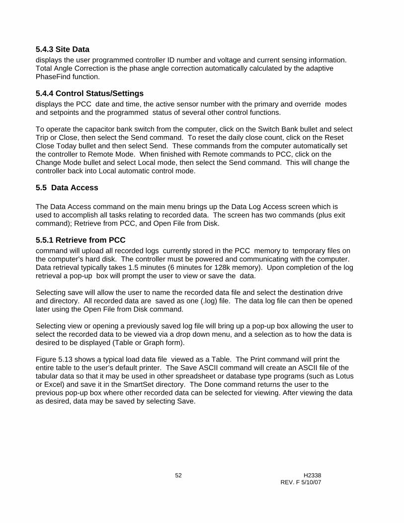
52 H2338 REV. F 5/10/07
5.4.3 Site Data displays the user programmed controller ID number and voltage and current sensing information. Total Angle Correction is the phase angle correction automatically calculated by the adaptive PhaseFind function.
5.4.4 Control Status/Settings displays the PCC date and time, the active sensor number with the primary and override modes and setpoints and the programmed status of several other control functions. To operate the capacitor bank switch from the computer, click on the Switch Bank bullet and select Trip or Close, then select the Send command. To reset the daily close count, click on the Reset Close Today bullet and then select Send. These commands from the computer automatically set the controller to Remote Mode. When finished with Remote commands to PCC, click on the Change Mode bullet and select Local mode, then select the Send command. This will change the controller back into Local automatic control mode.
5.5 Data Access The Data Access command on the main menu brings up the Data Log Access screen which is used to accomplish all tasks relating to recorded data. The screen has two commands (plus exit command); Retrieve from PCC, and Open File from Disk.
5.5.1 Retrieve from PCC command will upload all recorded logs currently stored in the PCC memory to temporary files on the computer’s hard disk. The controller must be powered and communicating with the computer. Data retrieval typically takes 1.5 minutes (6 minutes for 128k memory). Upon completion of the log retrieval a pop-up box will prompt the user to view or save the data. Selecting save will allow the user to name the recorded data file and select the destination drive and directory. All recorded data are saved as one (.log) file. The data log file can then be opened later using the Open File from Disk command. Selecting view or opening a previously saved log file will bring up a pop-up box allowing the user to select the recorded data to be viewed via a drop down menu, and a selection as to how the data is desired to be displayed (Table or Graph form). Figure 5.13 shows a typical load data file viewed as a Table. The Print command will print the entire table to the user’s default printer. The Save ASCII command will create an ASCII file of the tabular data so that it may be used in other spreadsheet or database type programs (such as Lotus or Excel) and save it in the SmartSet directory. The Done command returns the user to the previous pop-up box where other recorded data can be selected for viewing. After viewing the data as desired, data may be saved by selecting Save.
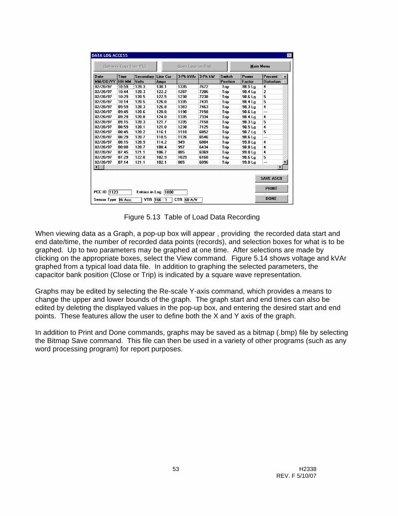
53 H2338 REV. F 5/10/07
Figure 5.13 Table of Load Data Recording When viewing data as a Graph, a pop-up box will appear , providing the recorded data start and end date/time, the number of recorded data points (records), and selection boxes for what is to be graphed. Up to two parameters may be graphed at one time. After selections are made by clicking on the appropriate boxes, select the View command. Figure 5.14 shows voltage and kVAr graphed from a typical load data file. In addition to graphing the selected parameters, the capacitor bank position (Close or Trip) is indicated by a square wave representation. Graphs may be edited by selecting the Re-scale Y-axis command, which provides a means to change the upper and lower bounds of the graph. The graph start and end times can also be edited by deleting the displayed values in the pop-up box, and entering the desired start and end points. These features allow the user to define both the X and Y axis of the graph. In addition to Print and Done commands, graphs may be saved as a bitmap (.bmp) file by selecting the Bitmap Save command. This file can then be used in a variety of other programs (such as any word processing program) for report purposes.

54 H2338 REV. F 5/10/07
Figure 5.14 Graph of Load Data Recording
5.6 Send PCC Time (Set Controller Clock) This Main Menu command is used to set the AutoCap’s internal time clock / calendar. Assure that your computer’s time / date is accurate before this command is initiated. The AutoCap controller must be powered and communicating with the computer. Clicking this command downloads the computer’s time / date as shown on the Main menu screen to the PCC (AutoCap), This command does not bring up a screen or acknowledgement; the AutoCap’s time / date can be verified by checking the Monitor/Operate screen, or on the controller’s LCD display if so equipped. TEST NOTE Bench testing with time entries which cross daylight saving time, will result in a one hour time change as seen in Monitor Mode with SmartSet.
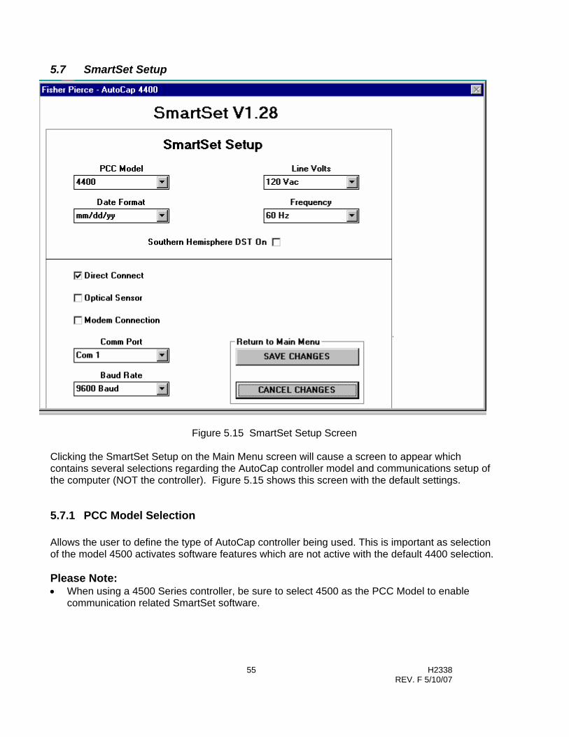
55 H2338 REV. F 5/10/07
5.7 SmartSet Setup
Figure 5.15 SmartSet Setup Screen
Clicking the SmartSet Setup on the Main Menu screen will cause a screen to appear which contains several selections regarding the AutoCap controller model and communications setup of the computer (NOT the controller). Figure 5.15 shows this screen with the default settings.
5.7.1 PCC Model Selection Allows the user to define the type of AutoCap controller being used. This is important as selection of the model 4500 activates software features which are not active with the default 4400 selection. Please Note: • When using a 4500 Series controller, be sure to select 4500 as the PCC Model to enable
communication related SmartSet software.

56 H2338 REV. F 5/10/07
5.7.2 Line Voltage and Frequency Selects the proper line voltage and frequency for the 4400/4500 control. The 4400/4500 is not programmable for different voltages or frequencies. This selection must be compatible with Controller Model Number (see section 9 Model Number and Ordering Information for details).
5.7.3 Southern Hemisphere DST This selection is used to modify the Daylight Savings time logic to accommodate the differences in the DST in the Southern Hemisphere.
5.7.4 Date Format The date field can be changed from North American to European format.
5.7.5 Communication Method Typically, these settings do not need to be changed in order to communicate locally with a Series 4400 controller through the RS-232 serial port. If you are unable to communicate with the controller with default settings, the most common adjustment required is to select a different computer serial communication port, which can be done by changing the Comm Port selection.
5.7.6 Direct Connect/Optical Sensor or Modem Three selections are available for communicating with the 4400/4500 AutoCap capacitor controllers. Direct connection is standard for all controllers. An RS-232-C communication port is provided on the front panel of the PCC for communications with SmartSet setup software. An optional optical port can be supplied and is located on the outside of the enclosure. Modem selection – Checked if an external modem is to be connected to the 4400 or if an optional internal modem is supplied with the 4500 series PCC. SmartSet allows the user to setup the computer modem, store phone numbers and dial the PCC directly from SmartSet setup software. With a modem connection, the PCC can be programmed, operated or recorded data can be up-loaded remotely.
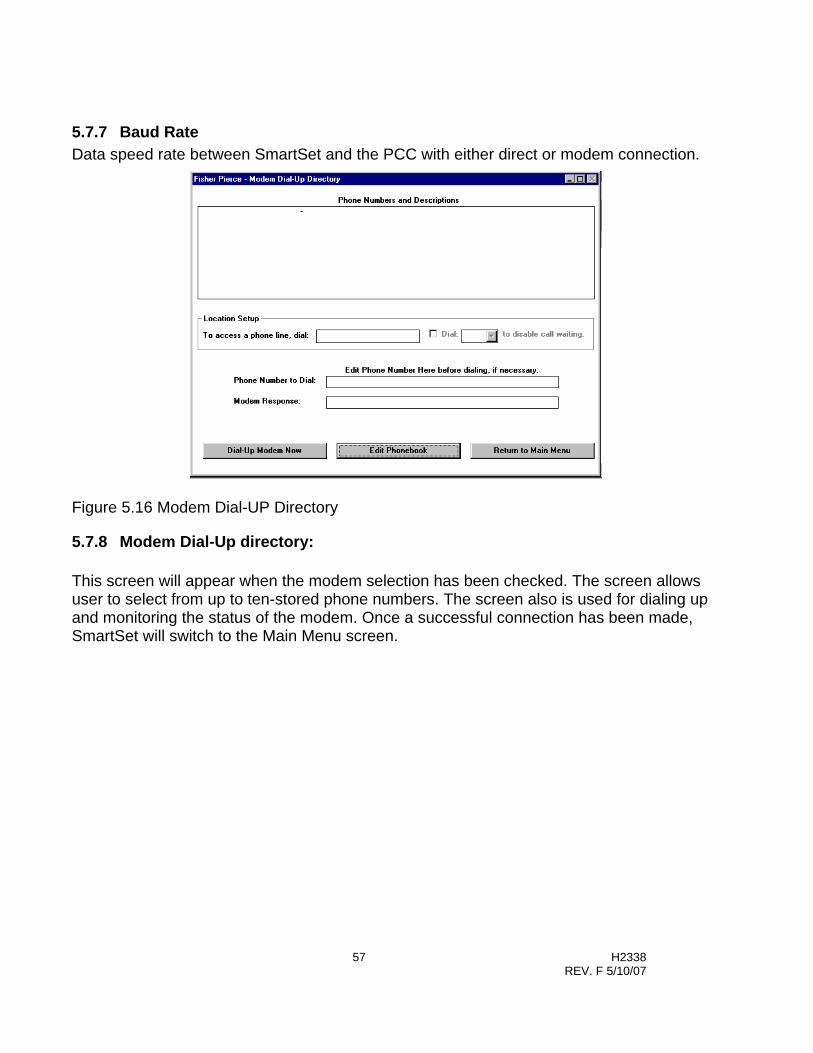
57 H2338 REV. F 5/10/07
5.7.7 Baud Rate Data speed rate between SmartSet and the PCC with either direct or modem connection.
Figure 5.16 Modem Dial-UP Directory
5.7.8 Modem Dial-Up directory: This screen will appear when the modem selection has been checked. The screen allows user to select from up to ten-stored phone numbers. The screen also is used for dialing up and monitoring the status of the modem. Once a successful connection has been made, SmartSet will switch to the Main Menu screen.
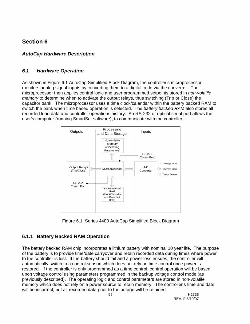
58 H2338 REV. F 5/10/07
Section 6
AutoCap Hardware Description
6.1 Hardware Operation As shown in Figure 6.1 AutoCap Simplified Block Diagram, the controller’s microprocessor monitors analog signal inputs by converting them to a digital code via the converter. The microprocessor then applies control logic and user programmed setpoints stored in non-volatile memory to determine when to activate the output relays, thus switching (Trip or Close) the capacitor bank. The microprocessor uses a time clock/calendar within the battery backed RAM to switch the bank when time based operation is selected. The battery backed RAM also stores all recorded load data and controller operations history. An RS-232 or optical serial port allows the user’s computer (running SmartSet software), to communicate with the controller.
Microprocessor
Non-volatileMemory
(OperatingParameters)
A/DConverter
Battery BackedRAM
(Clock/Calendarand Recorded
Data)
Output Relays(Trip/Close)
RS 232Comm Port
Voltage Input
Current Input
Temp Sensor
InputsProcessingand Data StorageOutputs
RS 232Comm Port
Figure 6.1 Series 4400 AutoCap Simplified Block Diagram
6.1.1 Battery Backed RAM Operation The battery backed RAM chip incorporates a lithium battery with nominal 10 year life. The purpose of the battery is to provide time/date carryover and retain recorded data during times where power to the controller is lost. If the battery should fail and a power loss ensues, the controller will automatically switch to a control season which does not rely on time control once power is restored. If the controller is only programmed as a time control, control operation will be based upon voltage control using parameters programmed in the backup voltage control mode (as previously described). The operating logic and control parameters are stored in non-volatile memory which does not rely on a power source to retain memory. The controller’s time and date will be incorrect, but all recorded data prior to the outage will be retained.

59 H2338 REV. F 5/10/07
6.2 Construction Features
6.2.1 Enclosure The AutoCap is housed in a weather proof enclosure designed for mounting near it’s associated capacitor bank. Opening the controller cover reveals the front panel. The front panel incorporates control switches, indicators, test jacks, and other required devices for local operation, indication and troubleshooting. The AutoCap enclosure is available in either Lexan or aluminum construction for the 4400 Series and Luran construction for the 4500 Series. Both are UV resistant and weather -proof NEMA 3R enclosures and are designed to accommodate a padlock( 3/8” hasp max.). The Lexan enclosure is available only as a meter socket mounted unit. The aluminum and Luran enclosures are available in a pole or bracket- mounting configuration. Pole and bracket- mounted units are to be wired to a terminal strip located within the enclosure. Installation information is provided in Section 7.
6.2.2 Circuit Boards The controller’s main internal components are two circuit boards; the controller board and the I/O (input/output) board. The controller board contains all computing circuitry including the controller microprocessor, memory chips and battery backed RAM chip. The I/O board contains input/output devices including terminal strip, transformers and output relays. The controller board sits directly beneath the controller front panel within an aluminum chassis and is accessed by removing the front panel. This is accomplished by removing the four panel hold-down screws and two toggle switch nuts.
6.3 Front Panel Features The AutoCap controller front panel and other main hardware features are illustrated in Figure 6.2. Note that the panel features between the 4400 and 4500 controllers are identical except where noted.
6.3.1 Automatic/Manual Toggle Switch With the switch in the “AUTO” (Automatic) position, the controller will function as programmed automatically in the Local mode. In the “MAN” (Manual) position, the momentary Trip/Close toggle switches are enabled allowing manual capacitor switching operation , and the automatic Local mode is disabled. Application Note: Ensure that the Auto/Man switch is returned to Auto after manual operations are complete.

60 H2338 REV. F 5/10/07
6.3.2 Trip/Close Toggle Switch The momentary Trip/Close toggle switch is enabled only when the Auto/Man switch is set to Man (Manual). The Close and Trip LED’s indicate the last command sent to the capacitor switches from the PCC. Switch inhibit condition is indicated by the Close Inhibit and Trip Inhibit LED’s. 6.3.2.1 Trip Position When momentarily set to the Trip position, the Trip output relay will close for the user programmed contact closure duration, causing the capacitor switches to operate into the open (Trip) position. The TRIP” LED will illuminate. If the “TRIP INHIBIT” LED illuminates upon setting switch to Trip, the “TRIP” LED will flash, indicating a timed delay is in effect in accordance with the programmed manual Trip switch delay, and the Trip operation is pending. When the inhibit timer is finished, the “ON: TRIP INHIBIT” LED will turn off, the “TRIP” LED will illuminate solidly and Trip output relay operation is initiated. Upon setting the switch to Trip, the ” CLOSE INHIBIT” LED will illuminate, indicating the programmed Trip to Close inhibit timer is in effect (typically 5 minutes minimum). This timer is a safety function which prevents the capacitor switch from Closing directly following a Trip, which allows the capacitor to discharge. 6.3.2.2 Close Position When momentarily set to the Close position and the capacitor switch in the Trip position, the Close output relay will close for the programmed contact closure duration, the “CLOSE” LED will illuminate and the capacitor switches will operate into a Close position. When the “CLOSE INHIBIT” LED illuminates upon setting the switch to Close, the “CLOSE” LED will flash, indicating a timed delay is in effect in accordance with the programmed manual Close switch delay and the Close operation is pending. When the inhibit timer is finished, the “CLOSE INHIBIT” LED will extinguish, the “CLOSE” LED will illuminate solidly and Close output relay operation is initiated.
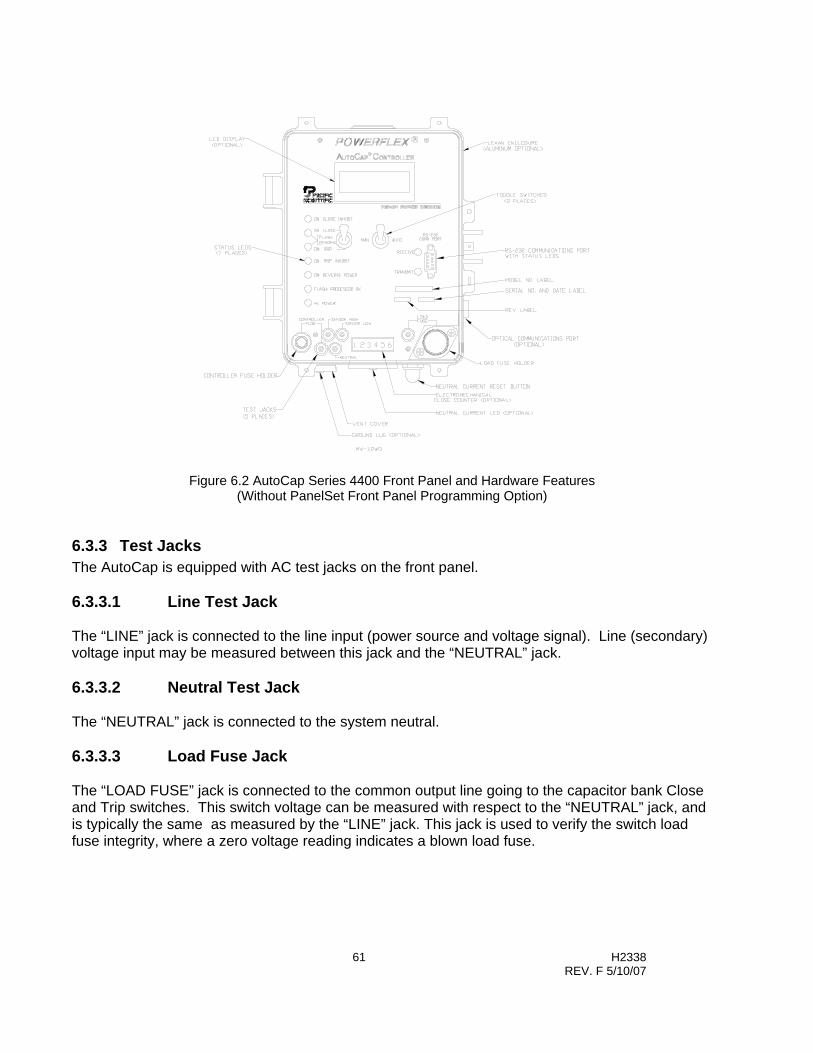
61 H2338 REV. F 5/10/07
Figure 6.2 AutoCap Series 4400 Front Panel and Hardware Features (Without PanelSet Front Panel Programming Option)
6.3.3 Test Jacks The AutoCap is equipped with AC test jacks on the front panel. 6.3.3.1 Line Test Jack The “LINE” jack is connected to the line input (power source and voltage signal). Line (secondary) voltage input may be measured between this jack and the “NEUTRAL” jack. 6.3.3.2 Neutral Test Jack The “NEUTRAL” jack is connected to the system neutral. 6.3.3.3 Load Fuse Jack The “LOAD FUSE” jack is connected to the common output line going to the capacitor bank Close and Trip switches. This switch voltage can be measured with respect to the “NEUTRAL” jack, and is typically the same as measured by the “LINE” jack. This jack is used to verify the switch load fuse integrity, where a zero voltage reading indicates a blown load fuse.
62 H2338 REV. F 5/10/07
6.3.3.4 Sensor High and Sensor Low Jacks When a line current signal is supplied by a line post current sensor (Fisher Pierce 1301 or Lindsey sensor), an AC voltage reading can be measured between the “SENSOR HIGH” and “SENSOR LOW” test jack for verification of line current signal. This voltage reading (typically below 15 Vac) can be converted to measured primary line current amplitude by multiplying by the appropriate sensor ratio (60 A/V for Fisher Pierce 1301). If a line current signal is supplied by a current transformer (CT) or if no line current signal is supplied, a measurement is not available.
6.3.4 Fuses Two fuses are supplied in the AutoCap for over current protection of both the controller itself as well as the capacitor bank switches. The PCC fuse is a 2A (typical) fuse for controller over current protection. The Load Fuse is a 10A (typical) fuse for capacitor switch over current protection. Both fuses are accessible by unscrewing the fuse holders located on the front panel. Integrity of the Load Fuse can be verified by measuring switching voltage across the “LOAD FUSE” and “NEUTRAL” test jacks. Spare fuses are mounted inside the enclosure cover.
6.3.5 LED Indicators LED’s are used for indication of controller status and operating information. LED’s (except Receive and Transmit LED’s) can be tested by resetting the controller, easily done by briefly removing the PCC fuse. 6.3.5.1 AC Power LED When the “AC POWER” LED is illuminated, AC power is being supplied to the controller. 6.3.5.2 Processor OK LED The “FLASH: PROCESSOR OK” LED will flash at approximately 2 times per second when the controller microprocessor is operating correctly. 6.3.5.3 Reverse Power LED When a reverse power condition is detected, the “ON: REVERSE POWER” LED will illuminate. Applicable only to controllers receiving a current signal input. 6.3.5.4 Trip Inhibit LED The “TRIP INHIBIT” LED will illuminate during a programmed manual trip switch delay, or during an Under voltage Inhibit event.

63 H2338 REV. F 5/10/07
6.3.5.5 Trip LED The “TRIP” LED will illuminate when the last command was a Trip operation during any control mode (manual, automatic or remote). A pending Trip operation is indicated when flashing. 6.3.5.6 Close LED The “CLOSE” LED will illuminate when the last command was a Close operation during any control mode (manual, automatic or remote). A pending Close operation is indicated when flashing. 6.3.5.7 Close Inhibit LED The “CLOSE INHIBIT” LED will illuminate following a Trip operation for a duration equal to the programmed Close inhibit delay after Trip (typically at least 5 minutes). This LED will also illuminate during the programmed manual Close switch delay, and when an under voltage switch inhibit function is active. Also, it will be illuminated during a Close inhibit due to the Anti-Hunt function or when the programmed daily Close count limit has been reached. 6.3.5.8 Receive and Transmit LED’s “RECEIVE” and “TRANSMIT” LED’s will flash rapidly when the controller is communicating with a PC through either the RS-232 or Optical communications port.
6.3.6 LCD Display (Optional) A two line read-only integrated LCD display provides real-time line readings of voltage, current, kW and kVAr. Controller status information such as ID number, time/date, primary and override control mode and setpoints is also shown. Daily Close operation count , close limit and neutral current reading are displayed. The display automatically scrolls through all information at a rate of approximately 5 seconds per screen.
6.3.7 Close Counter (Optional) An electromechanical Close counter provides a running total of all Close operations since manufacture of the control.
6.3.8 Communications Ports Two communication ports are available from which to choose on the AutoCap; a standard RS-232 port and optional Optical port. Either of these ports allow communications interface to a PC and both utilize Fisher Pierce SmartSet protocol.
64 H2338 REV. F 5/10/07
6.3.8.1 RS-232 Communication Port This interface is a standard EIA RS-232C 9-pin female serial, asynchronous port. Supplied standard with each controller. 6.3.8.2 Optical Communication Port (Optional) This Type 2 optical port carries the same data with the same protocol as the RS-232 communication port, while providing electrical isolation. This port conforms to ANSI standard C12,13-1991 (Electric metering time of use registers). The optical port is externally mounted allowing controller interface without opening the enclosure cover. Any standard optical head can be used in conjunction with the port.
6.4 Other Hardware Features
6.4.1 Neutral Current LED and Reset Switch (Optional) During a Neutral Current Lockout condition, an externally mounted LED is illuminated to alert personnel. Automatic capacitor bank switching is prevented during this condition. After the cause of the condition has been attended to, restoration of the controller to a normal automatic operating condition is performed manually by pressing the externally mounted reset switch.
6.4.2 Controller Vent A vent on the bottom of the enclosure is provided to prevent condensation within the controller. The vent incorporates a fine screen to prevent entrance of foreign objects. An aluminum cover, shields the vent from direct exposure to weather. The aluminum vent cover also houses a thermistor circuit board for ambient temperature sensing in controller’s equipped with a temperature sensor.
6.4.3 Ground Lug (Optional) A controller ground lug is typically located on the bottom of the enclosure adjacent to the vent cover.
6.4.4 12 Vdc Power Supply Connector (Series 4500 only) A 12 Vdc three pin connector is supplied only on Series 4500 controllers for use as a power supply for communication devices such as data radios and modems.
6.4.5 Solenoid Operated Switches The Controller can be programmed to operate either motor operated or solenoid type high voltage switches. Fisher Pierce recommends the use of long life solenoid operated vacuum switches. The solenoid operated switches require 100 to 300 ms of control voltage to operate. The AutoCap control can be programmed for .3 or 1 to 255 seconds of operation, in one-second intervals.

65 H2338 REV. F 5/10/07
Section 7
AutoCap Installation Instructions
7.1 Installation Instructions
7.1.1 Pre-Installation Notes The AC line power (nominal 120 or 240 Vac, as specified in the product model number), is used for both controller power and for voltage & VAr measurement. If the controller has line current input capability, a Fisher Pierce 1301, Lindsey Line Post Sensor or standard 5 Amp secondary Current Transformer (CT), is required to sense line current. Also, if the controller has neutral current input capability, a 5 amp secondary current transformer, a Fisher Pierce AT929 neutral current sensor or Voltage Transformer (VT), is required.
7.1.2 Model Number Guide The last 5 characters of the 4400 and 4500 model number determine the wiring / mounting configuration, enclosure type and voltage / frequency. 4400 Series Example Model Number (See page 75 for 4500 Series Model Number)
4411F - ETS - SM71A INSTALLATION
7.1.3 For All Installations Ensure that the capacitor controller’s AUTO / MAN switch is set to the MAN position before proceeding with capacitor controller installation.
Line Current 1 = 1301 / Lindsey 2 = CT, 0 = None
Factory Code
1 = 120Vac. 60Hz 2 = 240Vac, 60Hz 3 = 120Vac, 50Hz 4 = 220Vac, 50Hz
7 = Lexan8 = Aluminum
WiringConfiguration (see figures)
Neutral Current1 = AT929 2 = CT 3 = VT 0 = None
Front Panel C= Counter Only D=2-Line Display E= Both C&D P= PaneSet K= PanelSet & Counter N= None
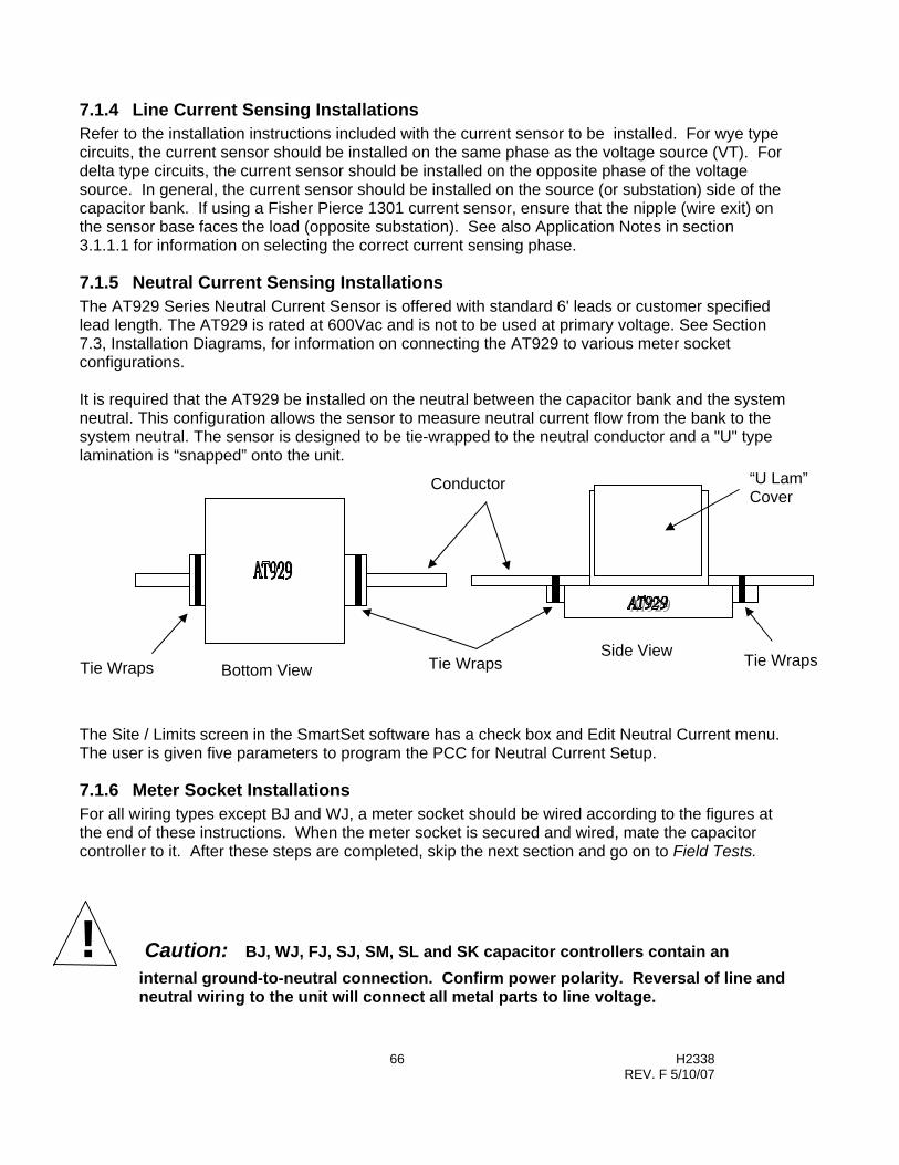
66 H2338 REV. F 5/10/07
7.1.4 Line Current Sensing Installations Refer to the installation instructions included with the current sensor to be installed. For wye type circuits, the current sensor should be installed on the same phase as the voltage source (VT). For delta type circuits, the current sensor should be installed on the opposite phase of the voltage source. In general, the current sensor should be installed on the source (or substation) side of the capacitor bank. If using a Fisher Pierce 1301 current sensor, ensure that the nipple (wire exit) on the sensor base faces the load (opposite substation). See also Application Notes in section 3.1.1.1 for information on selecting the correct current sensing phase.
7.1.5 Neutral Current Sensing Installations The AT929 Series Neutral Current Sensor is offered with standard 6' leads or customer specified lead length. The AT929 is rated at 600Vac and is not to be used at primary voltage. See Section 7.3, Installation Diagrams, for information on connecting the AT929 to various meter socket configurations. It is required that the AT929 be installed on the neutral between the capacitor bank and the system neutral. This configuration allows the sensor to measure neutral current flow from the bank to the system neutral. The sensor is designed to be tie-wrapped to the neutral conductor and a "U" type lamination is “snapped” onto the unit. The Site / Limits screen in the SmartSet software has a check box and Edit Neutral Current menu. The user is given five parameters to program the PCC for Neutral Current Setup.
7.1.6 Meter Socket Installations For all wiring types except BJ and WJ, a meter socket should be wired according to the figures at the end of these instructions. When the meter socket is secured and wired, mate the capacitor controller to it. After these steps are completed, skip the next section and go on to Field Tests.
! Caution: BJ, WJ, FJ, SJ, SM, SL and SK capacitor controllers contain an internal ground-to-neutral connection. Confirm power polarity. Reversal of line and neutral wiring to the unit will connect all metal parts to line voltage.
“U Lam” Cover
Conductor
Tie Wraps Side View
Bottom View Tie Wraps Tie Wraps

67 H2338 REV. F 5/10/07
7. 1.7 Pole or Wall Mount Installations For BJ and WJ wiring, connections to the capacitor controller are made via a bottom entry hole and the wiring made directly to the labeled terminal strip inside the controller as shown in the last figure of these instructions. The capacitor controller is shipped with a jumper installed between terminal 3 (Line), and terminal 4 (Relay). With this jumper in place the line voltage is (a) used to power the controller and used for voltage & VAr measurement and (b) connected to the armature of the Trip and Close relays via the 10 Amp Load Fuse. When the controller performs a Close operation, the Close relay momentarily closes and line voltage is applied to terminal 5 via the terminal 3 & 4 jumper, the Load Fuse and the Close relay contacts. When the controller performs a Trip operation, the Trip relay momentarily closes and line voltage is applied to terminal 6 via the terminal 3 & 4 jumper, the Load Fuse and the Trip relay contacts. To isolate the controller's voltage (power and measurements), from the relay switching voltage, remove the jumper between terminals 3 & 4. Now connect the controller's voltage to terminal 3 (Line, and the switching voltage to terminal 4 (Relay), while using terminal 2 for neutral. The capacitor controller is shipped with a jumper installed between terminal 1 (chassis Ground), and terminal 2 (Neutral). To isolate ground from neutral, remove the jumper between terminals 1 & 2.
! Warning: To avoid risk of injury, Current Transformer (CT) terminals MUST be shorted at the CT until installation is complete.
68 H2338 REV. F 5/10/07
7.2 FIELD TESTS
7.2.1 Power Check After installing the controller and subsequently when troubleshooting controller operation, the PROCESSOR OK LED on the front panel should be flashing. If the PROCESSOR OK LED is not flashing and no other LED’s are on, then verify that the controller has power applied. This can be accomplished by measuring the voltage between the NEUTRAL and LINE test jacks on the front panel. If line voltage is not measured, then check for improper installation wiring and check the PCC FUSE. Note: The LOAD FUSE can be checked similarly by measuring the voltage between the NEUTRAL and LOAD FUSE test jacks when either Trip or Close relay is activated. If the PROCESSOR OK LED is not flashing but is ON, reset the controller by removing and reinstalling the PCC FUSE.
7.2.2 Reverse Power Check (for controllers with current signal input) After the capacitor control is installed, check the Reverse Power LED. If not illuminated, proceed to Close / Trip Check below. If it is illuminated, perform the following steps; 1. Ensure that the polarity/wiring of both the voltage and line current sensors are correct or if
control does not have current signal input, select “none” in current signal selection in Site/Limits screen.
2. Ensure that a reverse power condition is not present. If a reverse power condition is actually
occurring (due to feeder switching, etc.), then proceed to Close / Trip Check below. 3. If polarity is correct and a reverse power condition is not present and the Reverse Power LED is
illuminated, then a software change must be made. Selection of phase rotation, current sensing phase or current signal direction must be changed in the software on the Site/Limits screen under the PCC Setup and the capacitor controller re-programmed. Refer to Angle Correction Table in Power Flow check (below).
7.2.3 Close / Trip Check After the capacitor controller is installed and powered-up, a manual close and trip may be performed to ensure proper wiring and system operation. To Close The Bank On-Line; 1. Ensure that the AUTO / MAN switch is set to MAN. 2. If the Close Inhibit LED is illuminated, then wait for it to extinguish 3. Push the momentary TRIP / CLOSE switch to CLOSE and release⎯the CLOSE LED will begin
to flash 4. Move a safe distance from the capacitor bank and wait for the Close Time Delay to expire⎯the
CLOSE LED will illuminate steadily 5. Verify that the capacitor bank switch closes

69 H2338 REV. F 5/10/07
To Trip The Bank Off-Line; 1. Ensure that the AUTO / MAN switch is set to MAN. 2. If the Trip Inhibit LED is illuminated, then wait for it to extinguish 3. Push the momentary TRIP / CLOSE switch to TRIP and release. If the TRIP LED begins to
flash then wait for the Trip Time Delay to expire. 4. Verify that the capacitor bank switch opens
7. 2.4 Power Flow Check (for controllers with current signal input) Observe the load current phase angle on the PCC display (MAN/SET/AUTO switch in MAN or AUTO) or in the SmartSet Monitor screen. Find the angle in the table below; if any correction is needed, use PanelSet or SmartSet. If SmatSet is used, be sure to retrieve the setup from the PCC before making setup changes; this precaution will avoid making unintended changes. Also, to avoid deleting old log data use SEND SETUP ONLY.
Angle Correction Table
Load Phase Angle Setup Correction
Degree Phase Rotation Change
Current Sensing Phase Current Signal Direction
340 - 0 None None None
0 - 60 None None None
60 - 120 None Advance Two Phases Opposite
120 - 180 None Advance One Phase None
180 - 240 None None Opposite
240 - 300 None Advance Two Phases None
300 - 340 None Advance One Phase Opposite Opposite Current Direction Means:
If now Forward, change to Reverse If now Reverse, change to Forward
Check the site for correct voltage transformer wiring and current signal type. See also Application Notes in section 3.1.1.1 for information on selecting the correct current sensing phase. The combination of Current Sensing Phase and Current Signal Direction can shift the load signal angle in 60-degree increments. VT Wiring (L-N or L-L) produces a 30-degree shift. The VT wiring is generally known from the installation, and is usually not used to correct the load angle. When the load angle is observed to be within the expected range, the REVERSE POWER LED should be off unless the line is known to be operating in reverse current flow. In the latter case allow for 180° load phase shift when using the angle correction table.

70 H2338 REV. F 5/10/07
1. Momentarily toggle the TRIP/CLOSE switch to CLOSE; the CLOSE LED should start flashing for a safety period before the bank closes ; this period (typically 60 sec) is to allow personnel to move a safe distance from the bank.
2. After the bank closes, notice the line voltage and Var reading (if a current signal is
connected) on the PCC display or SmartSet Monitor screen. 3. The close operation should have caused the line voltage to increase, although rapidly
changing load conditions can mask the effect of the bank. 4. The close operation should have also caused the line VArs
to go more leading, although rapidly changing load conditions can mask the effect of the bank. If the current sensor is on the load side of the bank, there will be little or no VAr change. In that case, use modified set points for VAr control settings.
5. If voltage or VAr changes do not indicate correct bank operation, observe the mechanical
position of the bank switch to confirm its position, and check the capacitor fuses.
7.2.5 FINAL SETTINGS Assure that the AUTO / MAN switch is in AUTO after the capacitor controller is field tested and ready to perform its functions.

71 H2338 REV. F 5/10/07
7.3 Installation Diagrams
FJ / GJ (Wye Wiring)
FJ / GJ (Delta Wiring)
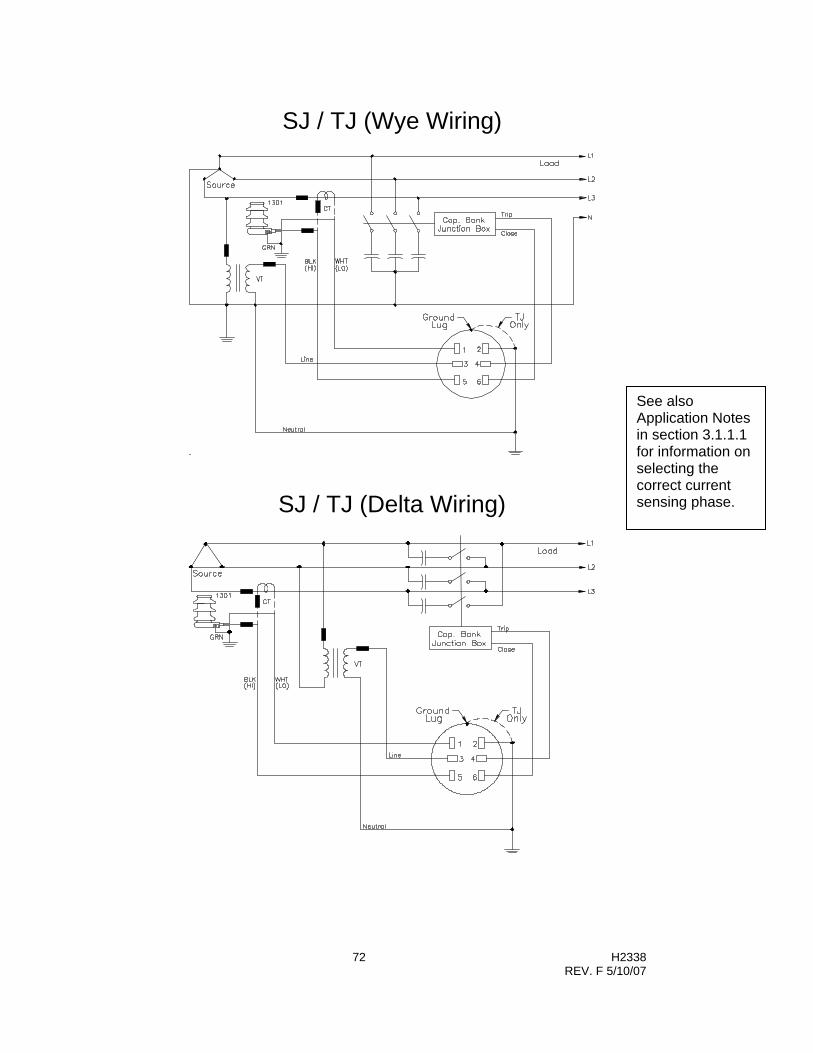
72 H2338 REV. F 5/10/07
SJ / TJ (Wye Wiring)
SJ / TJ (Delta Wiring)
See also Application Notes in section 3.1.1.1 for information on selecting the correct current sensing phase.

73 H2338 REV. F 5/10/07
SM / TM (Wye Wiring)
SM / TM (Delta Wiring)
See also Application Notes in section 3.1.1.1 for information on selecting the correct current sensing phase.

74 H2338 REV. F 5/10/07
SL / TL (Wye Wiring)
SK / TK (Wye Wiring)
See also Application Notes in section 3.1.1.1 for information on selecting the correct current sensing phase.

75 H2338 REV. F 5/10/07
BJ / WJ (Wye Wiring)
BJ / WJ (Delta Wiring)
GND = System ground N = Neutral L = Line RLY = Output relay armatures CL = Close TR = Trip CSH = Line Current Signal High CSL = Line Current Signal High NSH = Neutral Current Signal High NSL = Neutral Current Signal Low
See also Application Notes in section 3.1.1.1 for information on selecting the correct current sensing phase.

76 H2338 REV. F 5/10/07
Section 8
Troubleshooting Guide This guide is meant to address some basic possible problems and operating concerns. Many operating problems are usually associated with the application of the capacitor bank itself, including optimum size and location. The data recording functions of the AutoCap allow the user to verify optimum capacitor and controller operation.
8.1 No power to controller (“AC POWER” and other LED’s not on) Measure the voltage between the “PCC FUSE” and “NEUTRAL” test jacks. If line voltage is not measured here, check for improper wiring installation, and check the PCC fuse.
8.2 “PROCESSOR OK” LED not flashing (“AC POWER” LED on) Reset the controller microprocessor by removing and reinserting the PCC fuse.
8.3 Excessive Bank Switching If more than one switched capacitor bank is on the same feeder, and if using Var or Voltage based control operation, banks and/or regulators may be interacting causing the controllers to hunt. Possible solutions include utilization of the Anti-Hunt feature of the controller, which will restrain hunting caused by bank interaction or cycling loads. Excessive switching can also be exacerbated by switching time delays set too low.
8.4 Infrequent Bank Switching Typically this condition is caused by switching setpoints, which either usually always exceed or fall within switching parameter values found on the feeder. This can be confirmed by recording the switching parameter (such as Var or voltage) and comparing recorded values to the switching setpoint. Adjusting the controller setpoints may not always be the solution, as the capacitor bank size or location may not be optimal.
8.5 No Bank Switching Check for presence of conditions outlined for infrequent switching above. Ensure that any conditions, which may result in no switching, are not present including reverse power, neutral current lockout, or auto/man switch in man position.

77 H2338 REV. F 5/10/07
If capacitor switches do not operate, measure the voltage between the “LOAD FUSE” and “NEUTRAL” test jacks. If switching voltage is not measured here, check for improper wiring installation, and check the Load fuse.
8.6 Computer is not communicating with controller (Receive / Transmit LED’s are not blinking).
Check that cables and connections are secure. In SmartSet main menu click on Comm Setup and verify default settings shown in Section 5.7 appear. If default settings result in no communication, change Comm port selection until communications are established. If using optical port, make sure that proper selections are made for your particular optical head. If using a USB to RS-232 adapter, please note that some USB to RS-232 adapters may not provide the needed control signals required by the AutoCap Controller. In that case, please refer to Appendix D for more information on USB adapters.
8.7 Controller in Backup Voltage Mode This condition occurs for two reasons. The first is if the controller fails an Adaptive PhaseFind or Adaptive Var. The controller fails these tests if the current is to low or is fluctuating to quickly to get reliable measurements. The second reason for the controller to revert to Backup voltage mode is if the controller “RAM Battery” fails and the PCC was using the time clock for control.
8.8 RAM Battery Failure • The message "Ram Battery has Failed" can indicate a failure of the internal battery used in
the RAM memory, and will be displayed in the event of a power loss. Date and time data may also be corrupted. This condition does not render the PCC inoperable. Under this condition, the PCC is designed to first search the season schedule for a control strategy that does not use the time function. If a non-time based control strategy is not found, the control will revert to the Backup Voltage mode.
In this case, a new RAM Battery can be ordered from Joslyn Hi-Voltage Corporation and replaced in the field, or an RMA can be issued to have the controller sent in for repair/upgrade.
• This condition can also occur if the memory gets corrupted from such events as a surge due to lightning. In this case, reloading the controller program and data log configuration can clear the PCC and restore full functionality. To clear the unit:
1. From the main SmartSet menu, click on "Send PCC Time". 2. At this time the PCC has to be reprogrammed to the original settings.
If the original program was stored to disk or hard drive, click on "PCC Setup", then select “Retrieve Setup from Disk”. When the menu appears, select the appropriate setup file.
If the original setup file was not stored to disk, manually enter in the appropriate data to program the PCC.
3. From the View Setup screen, click on "Send to PCC". 4. At the next screen, click on "Send Setup and Data Log Configuration". The
SmartSet software will reprogram the PCC as was done originally. Note: All stored data will be reset.
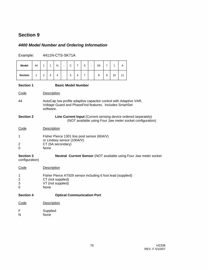
78 H2338 REV. F 5/10/07
Section 9
4400 Model Number and Ordering Information Example: 4411N-CTS-SK71A
Model
44
1
1
N
-
C
T
S
-
SK
7
1
A
Section
1
2
3
4
5
6
7
8
9
10
11
Section 1 Basic Model Number Code Description 44 AutoCap low profile adaptive capacitor control with Adaptive VAR,
Voltage Guard and PhaseFind features. Includes SmartSet software.
Section 2 Line Current Input (Current sensing device ordered separately) (NOT available using Four Jaw meter socket configuration) Code Description 1 Fisher Pierce 1301 line post sensor (60A/V)
or Lindsey sensor (100A/V) 2 CT (5A secondary) 0 None Section 3 Neutral Current Sensor (NOT available using Four Jaw meter socket configuration) Code Description 1 Fisher Pierce AT929 sensor including 6 foot lead (supplied) 2 CT (not supplied) 3 VT (not supplied) 0 None Section 4 Optical Communication Port Code Description F Supplied N None

79 H2338 REV. F 5/10/07
Section 5 Counter / Display Code Description C Electro-mechanical counter only D 2-line LCD display only (read only) E Electro-mechanical counter and 2-line LCD display (read only) K 2-Line LCD display with PanelSet (read/write) and Electro-mechanical counter P 2-Line LCD display with PanelSet only (read/write) N None Section 6 Temperature Sensor Code Description T Supplied N None Section 7 Memory Code Description S Standard 32k E Expanded 128k Section 8 External Wiring and Mounting Configuration Four Stab Meter Socket Mounting and Wiring
Sect. 8 Code
1 2* 3 4 5 6 External GND Lug*
Enclosure Current Inputs
F J L N/GND TR CL - - NO Lexan None G J L N/COM TR CL - - YES Lexan/Alum None
1 2 3 4
Four Jaw Meter Socket (View looking into socket)

80 H2338 REV. F 5/10/07
Six Stab Meter Socket Mounting and Wiring Sect. 8 Code
1 2* 3 4 5 6 External GND Lug*
Enclosure Current Inputs
S J** CSL N/GND L TR CSH CL NO Lexan Line only T J ** CSL N L TR CSH CL YES Lexan/Alu
m Line only
S M L N/GND CSL CSH TR CL NO Lexan Line only T M L N CSL CSH TR CL YES Lexan/Alu
m Line only
S L L N/GND NSL NSH TR CL NO Lexan Neut only T L L N NSL NSH TR CL YES Lexan/Alu
m Neut only
S K L N/GND/COM
NSH CSH TR CL NO Lexan Line + Neut
T K L N/COM NSH CSH TR CL YES Lexan/Alum
Line + Neut
Section 8 External Wiring and Mounting Configuration (Cont’d) Wrap-Around Pole Bracket Mounting with Terminal Strip
Sect. 8 Code
External GND Lug*
Enclosure Current Inputs
BJ Terminal strip as shown below
YES Alum None, Line, Neutral or Line + Neutral
Flat Wall Bracket Mounting with Terminal Strip
Sect. 8 Code
External GND Lug*
Enclosure Current Inputs
WJ Terminal strip as shown below
YES Alum None, Line, Neutral or Line +Neutral
1 2 3 4 5 6
Six Jaw Meter Socket (View looking into socket)

81 H2338 REV. F 5/10/07
Terminal Strip: (Aluminum Enclosure Only)
Note: Broken lines between terminals indicate removable jumper NOTES: * Neutral/Ground Wiring:
• For Lexan enclosure WITH ground lug: - Ground lug isolated from neutral • For Lexan enclosure WITHOUT ground lug: - Neutral connected to ground • For Aluminum enclosure (Ground lug standard):
- Removable jumper between neutral and ground ** Socket for CT shorting switch available for SJ and TJ wiring.
Notation Key: L = LINE N = NEUTRAL
TR = TRIP CL = CLOSE CSH = line current signal high CSL = line current signal low NSH = neutral current signal high NSL = neutral current signal low GND = Chassis ground RLY = Output relay contacts
Section 9 Enclosure Type Code Description 7 Lexan (Meter socket mounting only) 8 Aluminum Section 10 Voltage / Frequency Code Description 1 120 Vac, 60Hz 2 240 Vac, 60Hz 3 120 Vac, 50Hz 4 220 Vac, 50Hz Section 11 Factory Code
GND N L RLY CL TR CSH CSL NSH

82 H2338 REV. F 5/10/07
4500 Model Number and Ordering Information Example: 4511N-CTS-DDA-SK61B-
Model
45
1
1
N
-
C
T
S
-
D
D
A
-
SK
6
1
B
-
Section
1
2
3
4
-
5
6
7
-
8
9
10
-
11
12
13
14
-
15
Section 1 Basic Model Number Code Description 45 AutoCap programmable capacitor with two-way communications Section 2 Line Current Input (Current sensing device ordered separately) (NOT available using Four Jaw meter socket configuration) Code Description 1 Fisher Pierce 1301 line post sensor (60A/V)
or Lindsey sensor (100A/V) 2 CT (5A secondary) 0 None Section 3 Neutral Current Sensor Code Description 1 Fisher Pierce AT929 sensor including 6 foot lead (supplied) 2 CT (not supplied) 3 VT (not supplied) 0 None Section 4 Optical Communication Port Code Description F Supplied N None Section 5 Counter / Display Code Description C Electro-mechanical (counter 120VAC only) D 2-line LCD display only (read only) E Electro-mechanical counter and 2-line display (read only) N None

83 H2338 REV. F 5/10/07
Section 6 Temperature Sensor Code Description T Supplied N None Section 7 Memory Code Description S Standard 32k E Expanded 128k Section 8 Communications Protocol Code Description F SmartSet (no communication Micro or flash memory) D DNP 3.0 (communication Micro and flash memory installed) Section 9 & 10 Circuitry to Support Cellular/Modem Communications Code Description MB Modem installed – PSTN (public service telephone network) Radio Communications Code Description BA Installed – Metricom model 20043 BB Radio Ready – set up for Metricom radio DA Installed – Microwave Data Systems model 9310, 9810 DB Radio Ready - set up for Microwave Data Systems radio NC Communications ready or radio upgrade Note 1: Installed = Radio installation by FP, supplied by customer. Communication micro, flash memory and power supply included. Note 2: Radio Ready = Radio installed by customer. Radio bracket, antenna mount and
cables included. Communication micro, flash memory and power supply included.
Note 3: Communications Ready (defined by selecting “D” in section 8) = Radio bracket and cables not included. Power supply included. Comm. micro and memory installed.
Note 4: Radio Upgrade (defined by selecting code “F” in section 8) = Radio bracket and cables not included. Power supply included. Comm. micro and memory not installed (Controller board change out required for communications using a protocol other than FP Smartset, such as DNP3.0.)
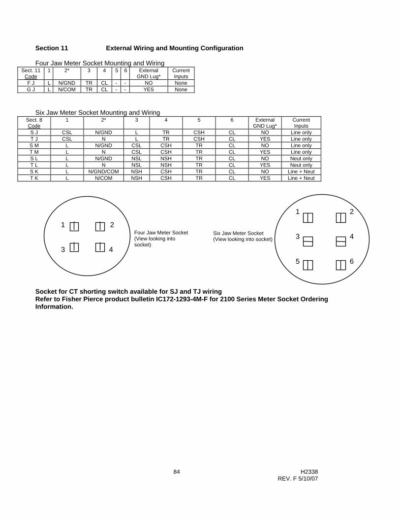
84 H2338 REV. F 5/10/07
Section 11 External Wiring and Mounting Configuration Four Jaw Meter Socket Mounting and Wiring
Sect. 11 Code
1 2* 3 4 5 6 External GND Lug*
Current Inputs
F J L N/GND TR CL - - NO None G J L N/COM TR CL - - YES None
Six Jaw Meter Socket Mounting and Wiring
Sect. 8 Code
1 2* 3 4 5 6 External GND Lug*
Current Inputs
S J CSL N/GND L TR CSH CL NO Line only T J CSL N L TR CSH CL YES Line only S M L N/GND CSL CSH TR CL NO Line only T M L N CSL CSH TR CL YES Line only S L L N/GND NSL NSH TR CL NO Neut only T L L N NSL NSH TR CL YES Neut only S K L N/GND/COM NSH CSH TR CL NO Line + Neut T K L N/COM NSH CSH TR CL YES Line + Neut
Socket for CT shorting switch available for SJ and TJ wiring Refer to Fisher Pierce product bulletin IC172-1293-4M-F for 2100 Series Meter Socket Ordering Information.
1 2 3 4 5 6
Six Jaw Meter Socket (View looking into socket)
1 2 3 4
Four Jaw Meter Socket (View looking into socket)
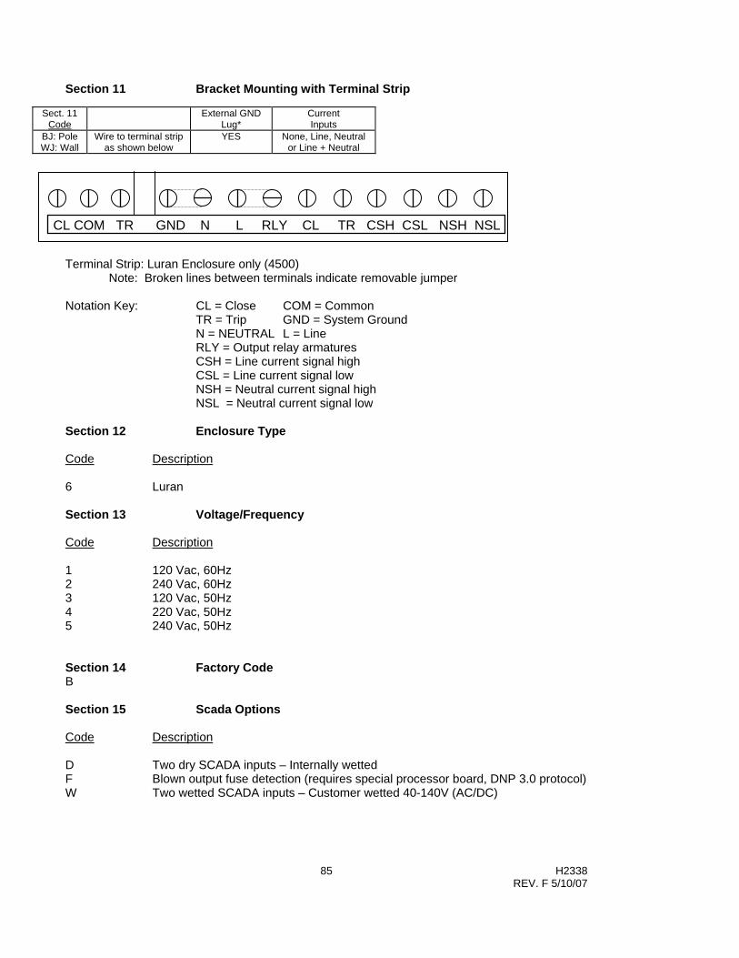
85 H2338 REV. F 5/10/07
Section 11 Bracket Mounting with Terminal Strip
Sect. 11 Code
External GND Lug*
Current Inputs
BJ: Pole WJ: Wall
Wire to terminal strip as shown below
YES None, Line, Neutral or Line + Neutral
Terminal Strip: Luran Enclosure only (4500)
Note: Broken lines between terminals indicate removable jumper Notation Key: CL = Close COM = Common
TR = Trip GND = System Ground N = NEUTRAL L = Line RLY = Output relay armatures CSH = Line current signal high CSL = Line current signal low NSH = Neutral current signal high NSL = Neutral current signal low
Section 12 Enclosure Type Code Description 6 Luran Section 13 Voltage/Frequency Code Description 1 120 Vac, 60Hz 2 240 Vac, 60Hz 3 120 Vac, 50Hz 4 220 Vac, 50Hz 5 240 Vac, 50Hz Section 14 Factory Code B Section 15 Scada Options Code Description D Two dry SCADA inputs – Internally wetted F Blown output fuse detection (requires special processor board, DNP 3.0 protocol) W Two wetted SCADA inputs – Customer wetted 40-140V (AC/DC)
CL COM TR GND N L RLY CL TR CSH CSL NSH NSL
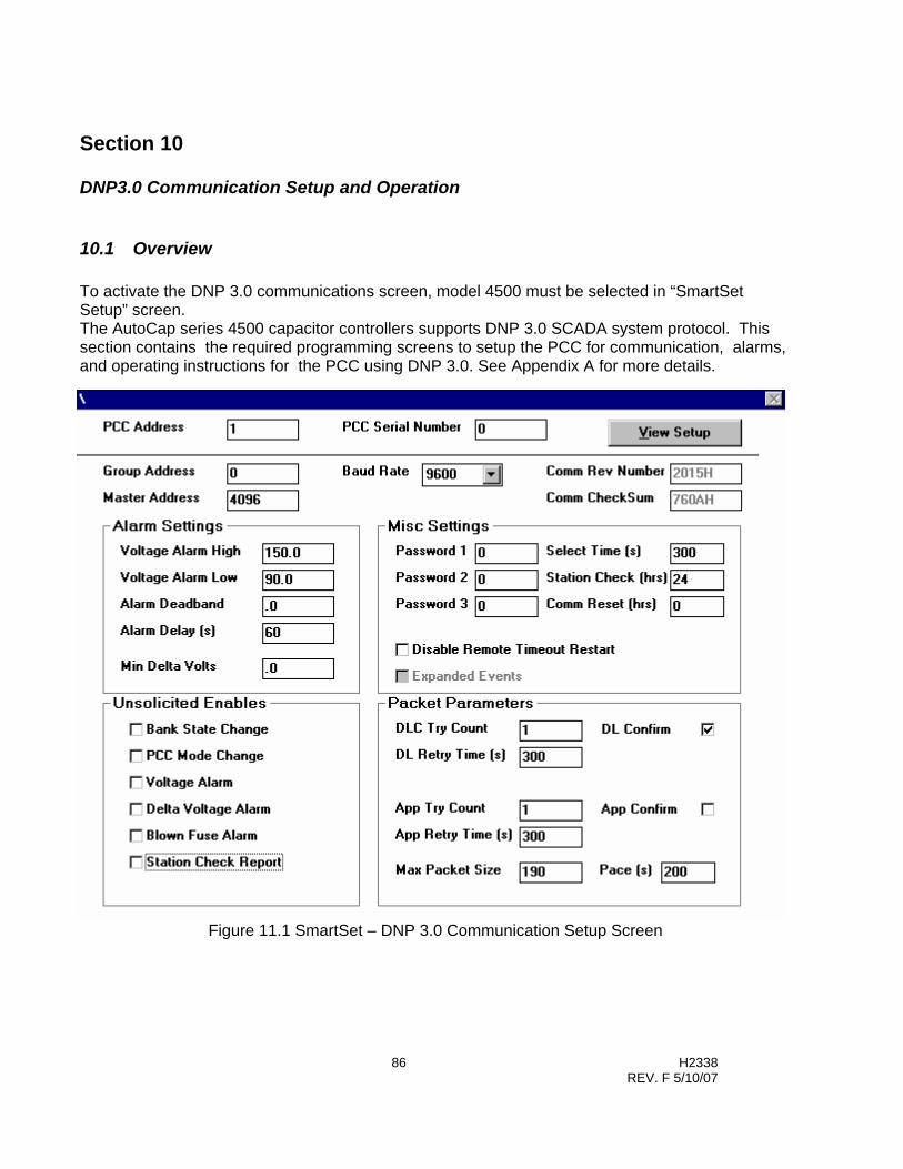
86 H2338 REV. F 5/10/07
Section 10
DNP3.0 Communication Setup and Operation
10.1 Overview To activate the DNP 3.0 communications screen, model 4500 must be selected in “SmartSet Setup” screen. The AutoCap series 4500 capacitor controllers supports DNP 3.0 SCADA system protocol. This section contains the required programming screens to setup the PCC for communication, alarms, and operating instructions for the PCC using DNP 3.0. See Appendix A for more details.
Figure 11.1 SmartSet – DNP 3.0 Communication Setup Screen
87 H2338 REV. F 5/10/07
Please Note (PCC Programming): • When sending setup parameters to the PCC the entire PCC set map including values are sent
A typical sequence to change a parameter would be to read the present setup map from the PCC, change the desired value or values, and then send the setup back to the PCC.
10.2 DNP 3.0 Settings
10.2.1 Programmable Capacitor Controller Address (PCC) The PCC address is used for communicating with the PCC. The PCC Address is used in the DNP packet header to identify the PCC. The default address is the PCC serial number (set at the time of manufacture). The PCC will only accept packets addressed to the PCC or Group address. In the event of a change out of a PCC in the field, the PCC Address can be updated.
10.2.2 PCC Serial Number The serial number is assigned and set at the time of manufacture. In the event of a change out of a PCC in the field, the PCC serial number can be updated to reflect the serial number of the replacement PCC.
10.2.3 Group Address The PCC will only accept packets addressed to the PCC or Group Address.
10.2.4 Master Control Address The PCC will send unsolicited packets using the Master Control Address. On power up the PCC will send a link reset to the preprogrammed Master Address. Unsolicited reports are also sent to the master address. Factory default is 4096.
10.2.5 Baud Rate Please Note: • To select and set Baud Rate go to “SmartSet Setup” screen at SmartSet Main Menu. The PCC will use the same baud rate for all communications. If a new baud rate is sent to the PCC, it will take effect only after the PCC is powered down/power-up or reset. The PCC’s serial port baud rate can be programmable to 1200, 2400, 4800, 9600, or 19200 baud.

88 H2338 REV. F 5/10/07
10.2.6 Comm Rev Number The communication revision number is used to identify the revision of communication firmware in the communication microprocessor flash memory and is a read-only field.
10.2.7 Comm CheckSum The communication checksum is generated upon PCC power-up and is a read only field. The CheckSum is compared to previous stored CheckSum, if they do not match it indicates a problem with the PCC memory device. An error is generated in DNP 3.0.
10.3 Alarm Settings
10.3.1 High Voltage Alarm The high voltage alarm value is for setting the voltage alarm detection threshold. Once this value is exceeded (for the time period set in the Alarm Delay field), the PCC will initiate a high voltage alarm.
10.3.2 Low Voltage Alarm The low voltage alarm value is for setting the voltage alarm detection threshold. Once this value is exceeded (for the time period set in the Alarm Delay field), the PCC will initiate a low voltage alarm.
10.3.3 Alarm Deadband The deadband alarm value is how far the voltage must recover from the High or Low Voltage Alarm (for the Alarm Delay period) for the voltage alarm condition to clear.
10.3.4 Alarm Delay The Alarm delay is used to prevent unnecessary alarms caused by transient voltage conditions. The Alarm delay should be set for a long enough period to prevent this condition. The High, Low Voltage and Deadband Alarms use the Alarm Delay.
10.3.5 Minimum Delta Volts The minimum voltage change expected from a capacitor bank operation. If the voltage change is less than this value, a delta voltage alarm will be detected. Setting the threshold to zero disables delta voltage alarm feature.
89 H2338 REV. F 5/10/07
10.4 Unsolicited Report Settings To report unsolicited events, the PCC’s global unsolicited report enable must be set. The PCC has several points (see points list) that may be reported as unsolicited events. If at least one point is selected for unsolicited report, the global unsolicited enable will be automatically enabled.
In addition the PCC’s global unsolicited enable may be remotely controlled as follows:
Enable with DNP function code 20, no objects Disable with DNP function code 21, no objects.
All unsolicited messages require an application layer confirm. The unsolicited report will be retried for the count specified in the App Retry Count field at intervals specified in the App Retry Time field. Responses to subsequent DNP requests will be held up until the unsolicited message retries out or a confirm to that unsolicited report is received. This could look like a PCC communications failure. Note that SmartSet does not confirm DNP messages.
10.4.1 Bank State Change Check to enable unsolicited bank state change reports. An unsolicited bank state change can occur from a manual operation or from a local control operation; such as a voltage exceeding a voltage control setpoint.
10.4.2 PCC Mode Change Check to enable unsolicited PCC control mode change reports. A PCC mode change report will be generated if the PCC is changed from Remote to Automatic or from Automatic to Remote.
10.4.3 Voltage Alarm Check to enable Unsolicited Voltage Alarms. An unsolicited alarm will be generated if the voltage exceeds the High or Low Voltage setpoint for the Alarm Delay period.
10.4.4 Delta Voltage Alarm Check to enable Unsolicited Delta Voltage Alarm reports. An Unsolicited Alarm will be generated if the minimum delta voltage alarm setpoint is not met.

90 H2338 REV. F 5/10/07
10.4.5 Blown Fuse Alarm (not standard – requires special hardware) Check to enable unsolicited Blown Fuse detection reports. The PCC monitors the condition of the load fuse (PCC fuse, not Cap fuse) after each Trip or Close operation. The PCC will initiate an Unsolicited Alarm if no voltage is detected across the load fuse.
10.4.6 Station Check Report Check to enable unsolicited station check reports. The PCC will report unsolicited Station Checks using the time set in the Station Check Interval. Please Note (On-Screen Help): • On-screen help is available to define each command and input required by pressing the F1
key. The F1 key will display a prompt box explaining the use and/or meaning of the input or command currently selected. Pressing the F1 key again will turn the prompt box off.
10.5 Packet Parameter Settings
10.5.1 Data Link Count (DLC Try Count) The number of data link tries the PCC will attempt. This count includes the initial packet.
10.5.2 Data Link Retry Time (DL Retry Time) The time in seconds between data link tries.
10.5.3 Data Link Confirm (DL Confirm) Check to enable data link confirmation on packets sent by the PCC.
10.5.4 Application Try Count The number of application tries the PCC will attempt. This count includes the initial packet.
10.5.5 Application Retry Time The time in seconds between application tries.
10.5.6 Application Confirm (App Confirm) Check to enable application confirmation on packets sent by the PCC.

91 H2338 REV. F 5/10/07
10.5.7 Maximum Packet Size The maximum packet size in bytes sent by the PCC.
10.5.8 Pace The minimum time in seconds between packets sent by the PCC.
10.6 Miscellaneous Settings
10.6.1 Passwords 1-3 The PCC has three passwords to protect analog output status (group 41 and control group 12) points from unauthorized change. The passwords are pre-assigned to PCC points. See the points list for this assignment. If a password is set to zero no password is required for points assigned to it. If a password is non zero then a password object (see points list) with the correct password must precede the analog output status or control point In addition some points are changeable ONLY when the PCC is in the remote mode. See points list for these points. Password 1 Password for level 1 objects. A zero disables level 1 password protection. Password 2 Password for level 2 objects. A zero disables level 2 password protection. Password 3 Password for level 3 objects. A zero disables level 3 password protection.
10.6.2 Select Time Enter in seconds the select before operate timeout. If this timer is exceeded between the select and the operate control blocks, the operate will not function.
10.6.3 Station Check Interval The time in hours between unsolicited station check reports. A zero disables unsolicited station check reports.
10.6.4 Disable Remote Timeout Restart Check to force remote timeout to local control. With this box checked remote timeout is restarted with the remote command only.
10.6.5 Expanded Events This must be checked for 4500 PCC models with communication microprocessors.

92 H2338 REV. F 5/10/07
10.7 PCC Operation Using DNP 3.0
10.7.1 PCC Power-Up When the PCC is powered up the PCC flashes its LED test pattern. When this is complete the communications processor reads the control processors setup and state. Total time is about 35 seconds. During this time the PCC communications is not available. Attempts to communicate may yield unpredictable results. On power up the PCC will send a reset link request packet to the stored master address. An ACK from the master will establish the PCC transmit link. The master should follow with a link request of its own to establish the PCC receive link.
10.7.2 PCC Mode Change When attempting to change PCC mode (local, remote, and manual) or operate the switch, the PCC will hold new actions until currently executing actions are complete. Specifically: When switching from manual to auto (which could be local or remote) with the panel toggle switch and the PCC is timing out a close after trip delay (close inhibit is on), the PCC will wait until the timeout is complete before changing modes. When commanding the PCC from local to remote mode and close inhibit is on due to trip close delay or anti-hunt delay the PCC will change modes after the close inhibit has expired. When switching from manual to auto and via local program or remote command a switch operation is called for, it will be delayed until the manual to auto delay is timed out. Please Note (delay mode changes): • Close inhibit due to max counts per day being exceeded does not delay mode changes.
10.7.3 PCC Remote Mode Timeout The PCC has two modes for automatically switching from remote to local control. 1. Standard
When switched to remote control the PCC starts the remote mode timer. The timer is set via SmartSet. When the timer expires, the PCC will switch back to local control. The timer is restarted with any communications with the PCC. If the DNP master constantly poles the PCC for event data the timer will be restarted with each poll and the PCC will stay in remote mode.
2. One Shot Setting the Disable Remote Timeout Restart flag either from SmartSet or DNP turns on the one shot mode. With this flag set the timer is only restarted when the PCC is set to remote control. Other communications will have no effect on the timer. When the timer expires, the PCC will switch back to local control.

93 H2338 REV. F 5/10/07
10.7.4 PCC Remote Reset PCC may be reset with Function 13 – no objects
10.7.5 DLC Reset DLC link reset requirements are ignored for SEND/NO REPLY EXPECTED packets .
Otherwise – For other types the link must be established in both directions using the LINK RESET request. If the link is not established the PCC will respond with a NAK.
On power up the PCC will send a reset link request packet to the stored master address. An ACK from the master will establish the PCC transmit link. The master should follow with a link request of its own to establish the PCC receive link. Any master link request will be ACKed by the PCC establishing a receive link. If a transmit link with that master is not established the PCC will automatically follow with its own link request. This will establish a link in both directions.The PCC can handle up to 4 active links.
94 H2338 REV. F 5/10/07
Section 11
Glossary Adaptive control features - See Adaptive Var, PhaseFind and Adaptive Voltage Guard function definitions. Adaptive test routine - A general term, which describes the automatic controller process used by the adaptive control, features. Adaptive Var control mode - An automatic controller process by which the AutoCap will program itself in Var control mode. The AutoCap contains logic, which defines proper Var switching setpoints based on measured capacitor bank size. Adaptive Voltage Guard, Voltage Guard - A function that prevents bank switching that will result in unacceptable line voltage conditions. Adaptive voltage guard automatically measures voltage rise due to capacitor switching to perform this function. The voltage rise can also be programmed by the user, bypassing adaptive functions. Anti-Hunt function - A function, which allows the AutoCap to identify a hunting condition (see def.) and apply a switching time delay in order to suppress this condition. Backup voltage control mode - A voltage control mode activated (if selected) should Adaptive Var or PhaseFind test fail and a reverse power control mode option. Battery Backed RAM - Component which stores recorded data and where the controller’s time clock / calendar resides. Nominal 10 year lithium battery life. Close - switch operation that puts the capacitor bank on-line. Daily Close Count Limit function - A function which prevents further switch operations when total daily Close operations reach a programmed limit. The daily Close count is reset each midnight. Daily Summary Recording - Data record of minimum and maximum daily value of voltage, current, kVAr and temperature. Default setup file - A setup file (x.def) provided by Fisher Pierce as an example setup file and found on the SmartSet disk. Downloading - Transferring data from a PC to the AutoCap in order to program the AutoCap. Hunting condition - A condition exemplified by excessive bank switching due to interaction from other switched banks on the same feeder, voltage regulators or due to cycling loads. Inhibit - In reference to switching operations, inhibit means to prevent or restrain switching due to certain existing condition(s).

95 H2338 REV. F 5/10/07
Load Data recording - Recording of selected line parameter values over a period of time, stored in AutoCap controller and retrieved by uploading. Parameters available are Voltage, Line Current, kW, kVAr, kVA, THD, Temperature and PF. Neutral Current Lockout function - A protective function which, when bank neutral current exceeds programmed limits, trips the bank off line and prevents switching. This condition is indicated by an external flashing LED. Optional feature requires neutral current input. Non-volatile memory - Components where programmed controller parameters (via the setup file) and controller logic reside in the AutoCap. Do not require power source for memory retention. Operations Recording - Data record of controller switch operation history and event recording. Override control mode - The secondary control mode, provides capacitor switching on a different control parameter which overrides (supercedes) the primary control mode when programmed override setpoints are reached. Phase correction angle - Calculated by the PhaseFind function, the angle added to the measured phase angle to compensate for phase rotation or reversed current sensor wiring. PhaseFind function - An adaptive function, which establishes the correct phase angle by locating the current sensor source in relation to the voltage source and compensating for phase rotation and current sensor, reversed wiring/polarity. Phase offset angle - The phase angle offset, introduced by the type of current sensor being used and automatically compensated for within the AutoCap after the type of sensor is selected by user. Primary control mode - The principal control mode used as a basis for capacitor switching under normal circumstances. Recording Interval - The length of time which a measured line parameter is averaged for load data recording. Selectable from 1 min. to 4 hours. Release setpoints - In reference to override control mode, these setpoints define when the control will return to primary control mode (released from override mode). Reverse Power condition - A condition in which line current reverses from normal direction, typically due to feeder sectionalizing and usually a temporary condition. Reversed Trip/Close Detection function - An automatic protective function that detects reverse wiring of the Trip/Close outputs. Only available in conjunction with the Adaptive Var function. Season - An user defined block of time which provides a means of changing control mode and/or setpoints depending upon time of year. Up to four seasons per year can be programmed into the AutoCap. Setup file - A computer file (with suffix .stp) created with SmartSet software and used to program the AutoCap controller.

96 H2338 REV. F 5/10/07
Switching time delay - A programmed amount of time which a control parameter must equal or exceed a switch setpoint before a switch operation occurs. Prevents excessive bank switching due to transient control parameter value. Trip - switch operation which takes the capacitor bank off line, i.e. to put switch in open position. Undervoltage Inhibit function - A function which prevents switching operations below a selected voltage to prevent capacitor switch damage. Uploading - Transferring data from the AutoCap to a Personal Computer in order to retrieve recorded data or setup from AutoCap. Voltage Bias control mode - A control mode that adjusts (biases) voltage control setpoints based on a secondary condition being met (a programmed time or temperature). The bias voltage is added to both the Trip and Close voltage setpoints.

97 H2338 REV. F 5/10/07
Appendix A – DNP 3.0 Communication Protocol Documentation This appendix consists of three sections, Device Profile Document, Implementation Table and Points List. DNP V3.00
DEVICE PROFILE DOCUMENT Fisher Pierce
PowerFlex® AutoCap 4500 Programmable Capacitor Control
Implementation Table and Point List accompany this document Highest DNP Level Supported: Level 1 for Requests Level 1 for Responses Device Function: Slave Notable objects, Functions, and/or qualifiers Supported in addition to the Highest DNP Levels Supported: Maximum Data Link Frame Size (octets): Configurable Maximum Application Fragment Size (octets): 2048 Transmitted 2048 Received Maximum Data Link Layer Retries: Field Configurable, range 0 to 255 Maximum Application Layer Retries: Field Configurable, range 0 to 255 Requires Data Link Layer Confirmation: Field Configurable, Enable / Disable Requires Application Layer Confirmation: Field Configurable, Enable / Disable Always required for Class 1,2,3 and Unsolicited responses. Restart Data Link Reset to Preprogrammed Master Field configurable Restart Unsolicited Response Header Configurable Timeouts while waiting for: Data Link Confirm: Field Configurable Complete Application Fragment: Fixed at 5 minute Application Confirm: Field Configurable Complete Application Response: Field Configurable Others: Unprocessed buffer timeout fixed at 5 minute Unsolicited Objects Reporting Configurable Global Unsolicited Enable/Disable with Functions Configurable 20 and 21

98 H2338 REV. F 5/10/07
Sends Unsolicited Responses: Field Configurable, Default is disabled Sends Static Data in Unsolicited Responses: Never Executes Control Operations: Write Binary Outputs: Always Select/Operate: Always Direct Operate: Always Direct Operate / No ACK: Always Count > 1: Never Pulse On: Never Pulse Off: Never Latch On: Always Latch Off: Always Queue: Never Clear Queue: Never Reports object with no specific variation request Reports: Binary input with status (v2) Binary input change with time (v2) Binary output with status (v2) 16 bit counter (v2) 16 bit counter change with time (v6) 16 bit analog input (v2) 16 bit analog change input with time (v4) 16 bit analog output status (v2) Time and date (v1) Reports object with no specific variation request Reports: Binary input change with time (v2) 16 bit counter change with time (v6) 16 bit analog change input with time (v4) Reports Class 1, 2, and 3 events Reports: Binary input change with time (v2) 16 bit counter change with time (v6) 16 bit analog change input with time (v4) Reports Binary Input Change Events when Fixed, as binary input with time no specific variation requested: Reports Time-Tagged Binary Input Change Fixed as Binary Input Change with Time Events when no specific variation requested: Default Counter Object / Variation: Object 22 / Variation 2 Close Operation Counter Counters Roll Over at: 16 bits Sends Multi-Fragment Response: No Sends Multi-Packet Response: Yes
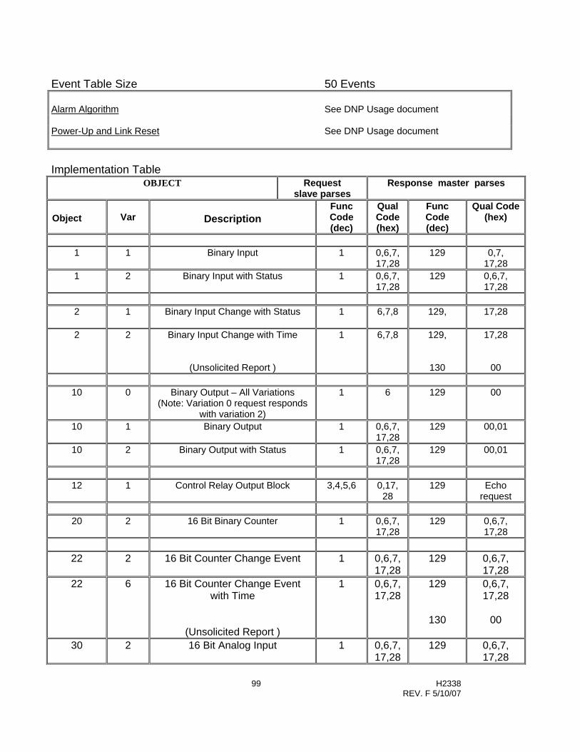
99 H2338 REV. F 5/10/07
Event Table Size 50 Events Alarm Algorithm See DNP Usage document Power-Up and Link Reset See DNP Usage document Implementation Table
OBJECT Request slave parses
Response master parses
Object
Var
Description
Func Code (dec)
Qual Code (hex)
Func Code (dec)
Qual Code (hex)
1 1 Binary Input 1 0,6,7,
17,28 129 0,7,
17,28 1 2 Binary Input with Status 1 0,6,7,
17,28 129 0,6,7,
17,28
2 1 Binary Input Change with Status
1 6,7,8 129,
17,28
2 2 Binary Input Change with Time
(Unsolicited Report )
1 6,7,8
129,
130
17,28
00
10 0 Binary Output – All Variations (Note: Variation 0 request responds
with variation 2)
1 6 129 00
10 1 Binary Output 1 0,6,7, 17,28
129 00,01
10 2 Binary Output with Status 1 0,6,7, 17,28
129 00,01
12 1 Control Relay Output Block 3,4,5,6 0,17,
28 129 Echo
request
20 2 16 Bit Binary Counter 1 0,6,7, 17,28
129 0,6,7, 17,28
22 2 16 Bit Counter Change Event 1 0,6,7,
17,28 129 0,6,7,
17,28 22 6 16 Bit Counter Change Event
with Time
(Unsolicited Report )
1 0,6,7, 17,28
129
130
0,6,7, 17,28
00
30 2 16 Bit Analog Input 1 0,6,7, 17,28
129 0,6,7, 17,28

100 H2338 REV. F 5/10/07
32 4 16 Bit Analog Change Event with Time
(Unsolicited Report )
1 0,6,7, 17,28
129
130
0,6,7, 17,28
00
40 0 Analog Output
(Note: Variation 0 request responds with variation 2)
1 0,6,7, 17,28
129 0,6,7, 17,28
40 2 16 Bit Analog Output
1 0,6,7, 17,28
129 0,6,7, 17,28
41 2 16 Bit Analog Output Output Block 3,4,5,6 0,17,
28 129 Echo
request
50 1 Time and Date 1 0,7 129 0,7
52 1 Restart Delay (coarse) 1 0,7 129 0,7 52 2 Time Delay (fine) 1 0,7 129 0,7
60 1 Class 0 Poll 1 06,07,
08 129
60 2 Class 1 Poll 1 06,07, 08
129
60 3 Class 2 Poll 1 06,07, 08
129
60 4 Class 3 Poll 1 06,07, 08
129
80 1 Internal Indications – Clear Reset 2 00
ind = 7
110 Octet Character String
Implemented for absolute memory access only
1,2 5 129 5
No Object
Cold Restart Function 13
No Object
Enable Unsolicited 20
No Object
Disable Unsolicited 21
DNP Points list for The 4500 Series Programmable Capacitor Controller (PCC)

101 H2338 REV. F 5/10/07
The following is a list of available data in Fisher Pierce's 4500 Programmable Capacitor Control. This points list will be implemented in a Level 2 subset of DNP V3.00. Although not listed this implementation will support Class access, SOEs, Time Synch. This implementation will also support unsolicited reporting, polled report by exception, and polled transactions. Notes: Class 1 types are alarm conditions Class 2 types are changes but are not considered alarms. The “–U” on a class type indicates unsolicited reporting capability. *Note 1 Changes not currently reported. *Note 2 These points will not change but appear for DNP consistency. *Note 3 Of no use but remains for backward compatibility. *Note 4 These points will not be recorded as changing but appear
for DNP consistency. Changes will be recorded in object 32 index 9 Group 01 - Binary input (bit status) Supported by Response function 129 Qualifier 0,6,7,17,28 Description Bit R/W Group Var Index Class Switch status 1 r 01 1,2 0 Manual mode 1 r 01 1,2 1 Local mode 1 r 01 1,2 2 Remote mode 1 r 01 1,2 3 Other mode 1 r 01 1,2 4 Close inhibit 1 r 01 1,2 5 Blown Fuse 1 r 01 1,2 6 Dummy station check enables 1 r 01 1,2 7
Point is used to send FC20 or 21 to enable unsolicited station checks
Note: bits with (DT) are ored to make IIN device trouble bit.

102 H2338 REV. F 5/10/07
Group 02 - Binary input change event Supported by Response function 129, 130 Qualifier 0,6,7 Description Bit R/W Group Var Index Class Switch status 1 r 02 1,2 0 1 Manual mode 1 r 02 1,2 1 2 Local mode 1 r 02 1,2 2 2 Remote mode 1 r 02 1,2 3 2 Other mode 1 r 02 1,2 4 2 Close inhibit 1 r 02 1,2 12 2 Blown Fuse 1 r 02 1,2 14 1 Dummy station check enables 1 r 01 1,2 15 4
Point is used to send FC20 or 21 to enable unsolicited station checks
Note: bits with (DT) are ored to make IIN device trouble bit. Group 10 - Binary output (bit status) Supported by Response function 129 Qualifier 0,6,7,17,28 Description Bit R/W Group Var Index Class Switch status 1 r 10 1,2 0 Remote mode 1 r 10 1,2 1 Clear neutral current lock 1 r 10 1,2 2 Enable global unsolicited 1 r 10 1,2 3

103 H2338 REV. F 5/10/07
Group 12 - Control points Supported by Request function 3,4,5,6 Qualifier 0,17,28 Description Bytes R/W Group Var Index Class Passwd
Level Operate bank 11 w 12 1 0 2/Rem
Pulse On with Trip/Close Pulse time comes from config file
Local control 11 w 12 1 1 2
Latch On = remote Latch Off - local
Clear neutral current lock 11 w 12 1 2 1
Latch On = clear Enable global unsolicited 11 w 12 1 3 1
Latch On = enable Note: Control block process ignore count, on time, and off time fields Group 20 - Counter Supported by Response function 129 Qualifier 0,6,7,17,28 Description Bytes R/W Group Var Index Total close count 3 r/w 20 2 0 Daily close count 3 r/w 20 2 1 Group 22 - Counter change Supported by Response function 129, 130 Qualifier 0,6,7 Description Bytes R/W Group Var Index Class Total operation count 3 r/w 22 2 0 2 Daily close count 3 r/w 22 2 1 *Note 1
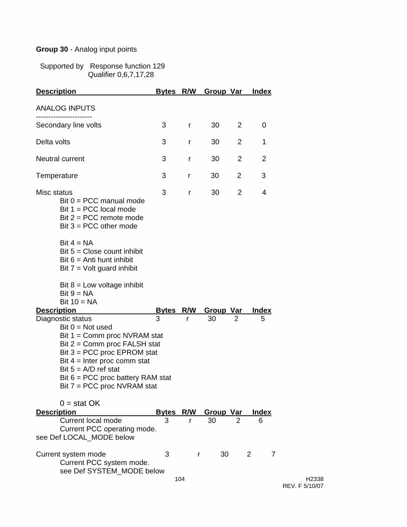
104 H2338 REV. F 5/10/07
Group 30 - Analog input points Supported by Response function 129 Qualifier 0,6,7,17,28 Description Bytes R/W Group Var Index ANALOG INPUTS ----------------------- Secondary line volts 3 r 30 2 0 Delta volts 3 r 30 2 1 Neutral current 3 r 30 2 2 Temperature 3 r 30 2 3 Misc status 3 r 30 2 4 Bit 0 = PCC manual mode Bit 1 = PCC local mode Bit 2 = PCC remote mode Bit 3 = PCC other mode Bit 4 = NA Bit 5 = Close count inhibit Bit 6 = Anti hunt inhibit Bit 7 = Volt guard inhibit Bit 8 = Low voltage inhibit Bit 9 = NA Bit 10 = NA Description Bytes R/W Group Var Index Diagnostic status 3 r 30 2 5 Bit 0 = Not used Bit 1 = Comm proc NVRAM stat Bit 2 = Comm proc FALSH stat Bit 3 = PCC proc EPROM stat Bit 4 = Inter proc comm stat Bit 5 = A/D ref stat Bit 6 = PCC proc battery RAM stat Bit 7 = PCC proc NVRAM stat 0 = stat OK Description Bytes R/W Group Var Index
Current local mode 3 r 30 2 6 Current PCC operating mode.
see Def LOCAL_MODE below Current system mode 3 r 30 2 7 Current PCC system mode. see Def SYSTEM_MODE below

105 H2338 REV. F 5/10/07
Group 32 - Analog input change event Supported by Response function 129, 130 Qualifier 0,6,7 Description Bytes R/W Group Var Index Class Secondary line volts 3 r 32 2 0 2 Delta volts 3 r 32 2 1 1 Neutral current 3 r 32 2 2 2 Temperature 3 r 32 2 3 *Note2 Misc status 3 r 32 2 4 *Note2 Bit 0 = PCC manual mode Bit 1 = PCC local mode Bit 2 = PCC remote mode Bit 3 = PCC other mode Bit 4 = NA Bit 5 = Close count inhibit Bit 6 = Anti hunt inhibit Bit 7 = Volt guard inhibit Bit 8 = Low voltage inhibit Bit 9 = NA Bit 10 = NA Description Bytes R/W Group Var Index Class Diagnostic status 3 r 32 2 5 3 Bit 0 = Not used Bit 1 = Comm proc NVRAM stat Bit 2 = Comm proc FALSH stat Bit 3 = PCC proc EPROM stat Bit 4 = Inter proc comm stat Bit 5 = A/D ref stat Bit 6 = PCC proc battery RAM stat Bit 7 = PCC proc NVRAM stat 0 = stat OK Description Bytes R/W Group Var Index Class Current local mode 3 r 32 2 6 *Note2 Current PCC operating mode. see Def LOCAL_MODE below Current system mode 3 r 32 2 7 2 Current PCC system mode. see Def SYSTEM_MODE below

106 H2338 REV. F 5/10/07
Group 40/41 - Analog input/output points Supported by Request function 3,4,5,6 Response function 129 Qualifier 0,7,8,17,18 Qualifier 0,6,7,8,17,28 Description Bytes R/W Group Var Index Class Passwd Level Incoming password 3 r/w 40/41 2 0 NA Place holder for password in incoming message Total operation count 3 r/w 40/41 2 1 3 Daily close count 3 r/w 40/41 2 2 1/REM Description Bytes R/W Group Var Index Class Delta volts alarm 3 r/w 40/41 2 3 1/REM Revert to local time-out 3 r/w 40/41 2 4 1/REM Neutral current threshold 3 r/w 40/41 2 5 1/REM Master address 3 r/w 40/41 2 6 3 PCC address 3 r 40/41 2 7 Read Only PCC Serial Number 3 r 40/41 2 8 Read Only Group 50 - Time points Supported by Request function 2 Qualifier 0,7 Description Bytes R/W Group Var Index Class Passwd Level PCC date and time 6 r/w 50 1 0 1 Group 52 - Time points Supported by Request function 1 Qualifier 0,7 Description Bytes R/W Group Var Index Class Restart delay (coarse) 2 r 52 1 0 Time delay (fine) 2 r 52 2 1
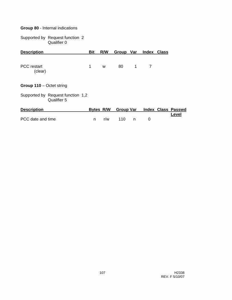
107 H2338 REV. F 5/10/07
Group 80 - Internal indications Supported by Request function 2 Qualifier 0 Description Bit R/W Group Var Index Class PCC restart 1 w 80 1 7 (clear) Group 110 – Octet string Supported by Request function 1,2 Qualifier 5 Description Bytes R/W Group Var Index Class Passwd
Level PCC date and time n r/w 110 n 0

108 H2338 REV. F 5/10/07
Appendix B – PanelSet Programming Instructions
PanelSet Local Control SetupSet the MAN / SET / AUTO switch to SET: Momentarily press theADVANCE/ENTER switch to ADVANCE to select the setup category.Then, press ENTER to accept an entry and step to the next selection.
CLOSE INHIBIT
AC POWER
PROCESSOR OK
TRIP INHIBIT
CL
TR
REVERSE POWER
PENDINGFLASH:
MAN
AUTO
RECEIVE
TRANSMIT
RS-232COMM PORT
LOADFUSEPCC
FUSE SENSOR LOWSENSOR HIGH
NEUTRAL
R
LINE
ON:
ON:
ON:
ON:
ON:
FLASH:
CLOSE-UP
TRIP-DOWN
SET
ENTER
ADVANCE
POWERFLEXUTO AP ONTROLLERA C C
FISHER PIERCE DIVISION
Site InstallPCC ID 1232
Increments Value orSetting Displayed.
Decrements Value orSetting Displayed.
Step to Next Category
Accept Setting and Moveto Next selection withinCategory
Enable PanelSet LocalProgramming
TM
Site wiring and equipment
Various time delays andswitching inhibitscommon to all seasons
Various functionscommon to allseasons
Local controlsetup for eachseason
Start AdaptiveTest if any havebeen selected.
Site InstallPCC ID 1232
Delays / InhibitsRLY Pulse 10 Sec
Other FunctionsMax CL / Day 10
Start ADAPT TSTN
Season 101/01 Thru 12/31
SETUP CATEGORYNote: The following functions cannot be changed using Panel Set. These changes can only be made using SmartSet.
• Date/Time • Season Dates • Data Log Configuration • Holiday Settings • Volt or VAR Bias • Power Up Trip • SCADA Override • In Timeclock mode:
o Changes for an individual day, PanelSet gives only 1 setting for 5 day weekday and 1 setting for 2 day weekend.

109 H2338 REV. F 5/10/07
B.1. To program the unit through PanelSet:
1. Set MAN/SET/AUTO switch to SET. 2. Momentarily press ADVANCE (A) to skip to the next category.
• The numbers after each line in the programming chart found later in this section refer to the position of each item within its category.
3. Use UP/DOWN switch to change setting. 4. Momentarily press ENTER (E) to save setting and move to next selection.
NOTES: • If any change is made in a Season, it is necessary to momentarily press ENTER for every
item in the Season, even if not changed. • Season start and end dates can be changed only through SmartSet. • Log configuration and holidays can be changed only through SmartSet. • Set switch to MAN or AUTO when sending setup from SmartSet.
• CAUTION: leaving switch in MAN or SET will disable auto cap switching.
B.2 To start the optional Adaptive Test through the panel set toggles, use the following procedure.
1. Move the bottom toggle switch to the SET position. 2. Use the top right toggle switch to ADVANCE to the various menus identified below. 3. Confirm and/or set the Rotation, Sensing Phase, and Direction to "Adaptive" by stepping
through the "Site Install" menu by using the top right toggle switch; toggle to the ENTER position.
• Set Voltage Guard to "Adaptive" by stepping through the "Other Functions" menu by using the top right toggle switch; toggle to the ENTER position.
• Set VAR to “Adaptive” by stepping through the “Season Mode” menu by using the top right toggle switch; toggle to the ENTER position.
• ADVANCE to the "Start ADAPT TST" menu using the top right toggle and then use the top left toggle to change the "N" to a "Y". Use the top right toggle switch to ENTER and save the setting change.
• Place the bottom toggle switch to the AUTO position to start the adaptive test.
The test will take approximately 20 minutes. After completion, confirm that the Adaptive Test was successful by reviewing the display window on the PCC to see the change in the associated settings from "Adaptive" to a new setting. If the control does not have entered settings, but still shows “Adaptive” for a particular function, it indicates the adaptive test was not successful. In this case, see section 5.3.6.3 for further instructions.

110 H2338 REV. F 5/10/07
Site InstallPCC ID: XXXXX [Identification number]
E - VT WIRING L-N 1L-L
E - VTR XX.X:1 2
E - PH ROTATION ABC 3 [Phase Rotation]CBA
ADAP [Adaptive]
E - CUR SIG PH A 4 [Current Signal Phase]BC
ADAPT [Adaptive]
E - CUR SIG DIRECTN 5 [Current Signal Direction]FORWARDREVERSEADAPTIVE
E - CUR SENSOR TYPE 6 [Current Sensor Type]CT XXX:5 [Press ENTER to enable XXX:5]
HI AC 1301 60A/V [High Accuracy 1301 60A/V]STD 1301 60A/V [Standard 1301 60A/V]
LINDSEY 100A/VLINDSEY 60A/V
SQUARE D 60A/VSQUARE D 100A/V
NONEE - CONDUCTOR DIA 7 [Applicable only to 1301]
INCH XX.X
E - CUR AMP CAL XX.X 8 [Current Amplitude Calibration error]
E - ANGLE OFFSET XXX 9 [Shift angle leading, degrees]
E - TEMP FORMAT 10FAHRENHEIT
CELSIUS
A
E [Save TEMP FORMAT and Return to PCC ID]
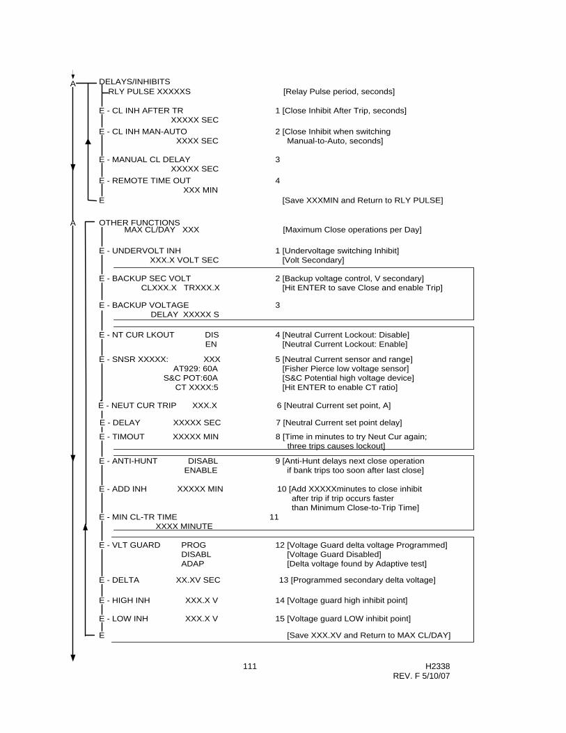
111 H2338 REV. F 5/10/07
A OTHER FUNCTIONS
E - UNDERVOLT INH 1 [Undervoltage switching Inhibit]XXX.X VOLT SEC [Volt Secondary]
E - BACKUP VOLTAGE 3DELAY XXXXX S
E - NT CUR LKOUT DIS 4 [Neutral Current Lockout: Disable]EN [Neutral Current Lockout: Enable]
E - SNSR XXXXX: XXX 5 [Neutral Current sensor and range]AT929: 60A [Fisher Pierce low voltage sensor]
S&C POT:60A [S&C Potential high voltage device]CT XXXX:5 [Hit ENTER to enable CT ratio]
E - NEUT CUR TRIP XXX.X 6 [Neutral Current set point, A]
E - DELAY XXXXX SEC 7 [Neutral Current set point delay]
E - TIMOUT XXXXX MIN 8 [Time in minutes to try Neut Cur again; three trips causes lockout]
E - ANTI-HUNT DISABL 9 [Anti-Hunt delays next close operationENABLE if bank trips too soon after last close]
E - ADD INH XXXXX MIN 10 [Add XXXXXminutes to close inhibit after trip if trip occurs faster than Minimum Close-to-Trip Time]
E - MIN CL-TR TIME 11XXXX MINUTE
E - VLT GUARD PROG 12 [Voltage Guard delta voltage Programmed]DISABL [Voltage Guard Disabled]ADAP [Delta voltage found by Adaptive test]
E - DELTA XX.XV SEC 13 [Programmed secondary delta voltage]
E - LOW INH XXX.X V 15 [Voltage guard LOW inhibit point]
E - BACKUP SEC VOLT 2 [Backup voltage control, V secondary]CLXXX.X TRXXX.X [Hit ENTER to save Close and enable Trip]
E - HIGH INH XXX.X V 14 [Voltage guard high inhibit point]
E [Save XXX.XV and Return to MAX CL/DAY]
MAX CL/DAY XXX [Maximum Close operations per Day]
A DELAYS/INHIBITSRLY PULSE XXXXXS [Relay Pulse period, seconds]
E - CL INH AFTER TR 1 [Close Inhibit After Trip, seconds]XXXXX SEC
E - CL INH MAN-AUTO 2 [Close Inhibit when switchingXXXX SEC Manual-to-Auto, seconds]
E - MANUAL CL DELAY 3XXXXX SEC
E - REMOTE TIME OUT 4XXX MIN
E [Save XXXMIN and Return to RLY PULSE]

112 H2338 REV. F 5/10/07
E – AUX HI V TR XXX.X Volts 16 [Aux Hi Voltage Trip. Recommended range 140 – 160] E – DLY XX.X Seconds 17 [ 0 to 60 s. Close ops inhibited until timeout] E – CL INH XX Minutes 18 [ 1 to 30 m. Close ops inhibited due to high volt trip]
A SEASON 1
E - MM/DD THRU MM/DD 1 [Start and end dates of selected season; dates cannot be changed]
E - SEASON X MODE 2 [Primary function of selected season]PROG VARADAP VARSEC VOLT
PRI CURRENTTIME
HI TEMP CLLO TEMP CLOSE
SCADANO-OP
E - CLOSE XXXXX 3 [Close set point of selected function]
E - TRIP XXXXX 4 [Trip set point of selected function]
E - PRIMARY FUNCTION 5ST PT DLY XXXXXS
234
E - SET AUTO TO STRT 1 [If Yes selected, to start adaptive tests set MAN/SET/AUTO switch to AUTO]
START ADAP TST N [Do not Start Adaptive Tests Y [Enable start of tests, if any are set]
A [Return to Site Install whether or not adaptive tests have been enabled. START ADAP TST will be set to N.]
A
E - REVERSE POWER 8IGNORE
INHIBIT ALL SW [Inhibit all switching]TR AND INHIBIT [Trip the bank and inhibit all switching]CL AND INHIBIT [Close the bank and inhibit all switching]
BACKUP SEC VOLT [Change function to Backup Voltage]MODIFIED VAR [If a VAr control, modify set points]
E - OVERRIDE NONE 6VOLTAGE
TIME [Delay irrelevant for Time Override]HI TEMP
LO TEMPSCADA [Delay irrelevant for SCADA Override]
E - OVRRD DLY XXX 7
E - DELAY XXX SEC 10
E - RVS PWR - XXX.X 9 [Reverse power threshold; KW primary]
E [Save XXX SEC and return to SEASON 1]

113 H2338 REV. F 5/10/07
Appendix C – Adaptive Test Error Messages and Corrective Actions
Event Log Description Possible Cause Result Corrective Action
Fail - Reversed Trip/Close wiring
Trip and Close wiring reversed
All automatic switching operations halted
Correct wiring to Trip and Close actuators
VAr Fail - Low Delta Low current due to light customer load
VAr Fail - Low Delta Cap bank switching problem
VAr Fail - Low Delta Current sensor on load side of cap bank
VAr Fail - Low Delta Extreme fluctuating loads during the Adaptive Test
Unit will revert to Backup Voltage Control according to the settings under the Site Limits screen.
Adaptive VAR Test
Reverse Power CT / Sensor leads reversed
Note: Only an issue if phase find not selected.
Correct noted problems and re-run Adaptive test or manually input settings and clear adaptive "flags". See Note 1 below. See also Section 3.1.1.1 in the 4400 manual for help with calculating Close and Trip VAR setpoints.
Fail - Reversed Trip/Close wiring
Trip and Close wiring reversed
All automatic switching operations halted
Correct wiring to Trip and Close actuators
Ang Fail - Can't Find Low current due to light customer load
Ang Fail - Can't Find Current sensor not connected / defective sensor
Ang Fail - Can't Find Load very leading due to fixed cap bank / capacitive load
Adaptive Angle Test
Ang Fail - Can't Find Programming / setup error - Incorrect current sensor selected
Unit will revert to Backup Voltage Control according to the settings under the Site Limits screen.
Correct noted problems and re-run Adaptive test or manually input settings and clear adaptive "flags". See Note 1 below. See also Application Notes in section 3.1.1.1 for information on selecting the correct current sensing phase.
Fail - Reversed Trip/Close wiring
Trip and Close wiring reversed
All automatic switching operations halted
Correct wiring to Trip and Close actuators
Volt Guard Fail - Noisy
"Noisy" AC voltage. Cannot measure unstable voltage readings.
Fail - Voltage Guard not activated.
Voltage Guard Test
Volt Guard Fail - Low delta
Very stiff system / voltage regulation on line. Delta voltage < 1.5 volts
Fail - Voltage Guard not activated.
Manually input settings and clear adaptive "flags". See Notes 1 and 2 below.
Note 1: If the control was unsuccessful in performing the Adaptive Test, the following is recommended: a.) Change all Adaptive settings to actual settings and remove the check mark in the Adaptive ON setting. b.) Run the Adaptive test again with all the Adaptive functions turned off. This will reset the internal Adaptive "flags". Note 2: Go to Monitor mode and record reported voltage. Manually switch bank. Go back to monitor mode and record new voltage. At the Site Limits screen, enter delta voltage multiplied by 1.25. For help with selecting the other related settings, press F1 while cursor is in desired field. Be sure to also set the upper and lower voltage limits.

114 H2338 REV. F 5/10/07
Appendix D – USB to RS-232 Adapters In most cases you can purchase a USB to RS-232 serial cable adapter, install the manufacturer’s software “drivers”, and communicate with the 4400. The Radio Shack 26-183 and Keyspan USA-19HS have been tested and are recommended.
If using a GoldX (or similar) USB adapter however, you may not be able to communicate with the 4400. If communication cannot be established, the probable cause is a de-asserted CTS signal coming from the 4400. If the USB Adapter responds to this signal, it will halt communication. To circumvent this situation, it will be necessary to construct an adapter that removes this control line. To construct the adapter, see the Construction Details on the next page.
Radio Shack 26-183 RECOMMENDED
Keyspan USA-19HS RECOMMENDED
GoldX GXMU-1200 NOT Recommended

115 H2338 REV. F 5/10/07
CCoonnssttrruuccttiioonn DDeettaaiillss::
1. You can purchase the following components for approximately $5 from Newark Electronics. Call 1-800-4-NEWARK, or order online at www.newark.com, or purchase the equivalent from the supplier of your choice.
9 Pin Male solder tail connector. Newark Part No: 87N484.
9 Pin Female solder tail connector Newark Part No: 87N488
Cover Newark Part No: 31C0447
2. Solder about 4 inches of wire on Pins 2, 3, 4 and 5 on the Male connector. Connect only the 4
lines as shown in the diagram below. (You may want to use different color wires for simplicity of construction)
3. Route the wires through the cover. 4. Solder the other ends of the wire to the same numbered pin on the Female connector, as
shown in the diagram below. eg: Pin 2 Male to Pin 2 Female, etc. 5. Snap the connector shells into the housing. 6. Install the Adapter between the USB Adapter and the RS-232 port on the 4400.
9 Pin Male 9 Pin Female Pin 1 < < Pin 1 Pin 2 < < Pin 2 Pin 3 < < Pin 3 Pin 4 < < Pin 4 Pin 5 < < Pin 5 Pin 6 < < Pin 6 Pin 7 < < Pin 7 Pin 8 < < Pin 8 Pin 9 < < Pin 9
Connection Diagram
Male Pins - Solder Side
Female Pins - Solder Side

116 H2338 REV. F 5/10/07
Appendix E - Manual Revisions Changes from Rev D Manual to Rev E Manual
• Section 3.1.1.1, “VAr Control”, has been modified by adding additional application information relating to the correct phase placement of the current sensor. Also, many references to this section have been inserted throughout the manual.
• Section 3.1.2.3, “Temperature Override”. The text has been expanded to fully explain High and Low temperature override. Also, a graph was added to illustrate this function.
• Section 4.3, “Connecting a PC to the AutoCap Controller”. A note was added for USB to RS-232 converters.
• Section 5.3.6, “Adaptive Test”, has been extensively modified to elaborate on how this function tests the system, how to select which tests are to be run, and how to start the Adaptive Test. Also, a new section 5.3.6.3 has been added to give instructions on how to cancel an unsuccessful Adaptive Test and how to manually program in the desired setpoints.
• Section 7.2.4, “Power Flow Check”. The chart has been re-formatted.
• Section 8, “Troubleshooting Guide”. In section 8.6, additional information was added pertaining to USB to RS-232 converters. Also, in section 8.8, additional information was added for clearing the “RAM Battery Failure” message.
• Section 10.4.5, “Blown Fuse Alarm”. A note was added to state that this DNP3.0 function is only available with special hardware.
• Appendix B was modified to add missing information to the chart on Auxiliary Hi-Voltage settings. Also, a section was added to explain how to initiate the Adaptive Test using the panel set toggle switches.
• Appendix C, “Adaptive Test Error Messages and Corrective Actions”, was added.
• Appendix D, “USB to RS-232 Adapters”, was added.
• Appendix E, “Manual Revisions” was added.
Changes from Rev E Manual to Rev F Manual
• Section 2, Corrected numerous typographical errors in the specifications.
• Section 3.1.1.4, Clarified Time Clock operation.
• Section 7.1.5, Added section on Neutral Current Sensor Installation.
• Appendix B, added text block showing functions NOT available using Panel Set.
• Appendix D, added information for Radio Shack RS-232 to USB adapter.