auto scanning densitometer -...
TRANSCRIPT
DTP32HS Auto Scanning Densitometer
Operator’s Manual


D T P 3 2 H S D E N S I T O M E T E R
1
CE Declaration Manufacturer's Name: X-Rite, Incorporated Manufacturer's Address: 3100 44th Street, S.W. • Grandville, Michigan • U.S.A. Model Name: Densitometer Model No.: DTP32HS Directive(s) Conformance: EMC 89/336/EEC LVD 73/23/EEC
Federal Communications Commission Notice This equipment has been tested and found to comply with the limits for a Class B digital device, pursuant to Part 15 of the FCC Rules. These limits are designed to provide reasonable protection against harmful interference in a residential installation. This equipment generates, uses, and can radiate radio frequency energy and, if not installed and used in accordance with the instructions, may cause harmful interference with radio communications. However, there is no guarantee that interference will not occur in a particular installation. If this equipment does cause harmful interference to radio or television reception, which can be determined by turning the equipment off and on, the user is encouraged to try to correct the interference by one or more of the following measures: reorient or relocate the receiving antenna; increase the separation between the equipment and receiver; connect the equipment into an outlet on a circuit different from that to which the receiver is connected; and/or consult the dealer or an experienced radio/television technician for help.
NOTE: Shielded interface cables must be used in order to maintain compliance with the desired FCC and European emission requirements.
Industry Canada Compliance Statement This Class B digital apparatus meets all requirements of the Canadian Interference-Causing Equipment Regulations. Cet appareil numérique de la classe B respecte toutes les exigences du Règlement sur le matériel brouilleur du Canada.
Equipment Information
Use of this equipment in a manner other than that specified by X-Rite, Incorporated may compromise design integrity and become unsafe. WARNING: This instrument is not for use in explosive environments. ADVERTENCIA - NO use este aparato en los ambientes explosivos. AVVERTIMENTO - NON usare questo apparecchio in ambienti esplosivi. WARNUNG: Das Gerät darf in einer explosiven Umgebung NICHT verwendet werden. AVERTISSEMENT: Cet instrument ne doit pas être utilisé dans un environnement explosif.
Proprietary Notice The information contained in this manual is derived from patent and proprietary data of X-Rite, Incorporated. The contents of this manual are the property of X-Rite, Incorporated and are copyrighted. Any reproduction in whole or part is strictly prohibited. Publication of this information does not imply any rights to reproduce or use this manual for any purpose other than installing, operating, or maintaining this instrument. No part of this manual may be reproduced, transcribed, transmitted, stored in a retrieval system, or translated into any language or computer language, in any form or by any means, electronic, magnetic, mechanical, optical, manual, or otherwise, without the prior written permission of an officer of X-Rite, Incorporated.
This product may be covered by one or more patents. Refer to the instrument for actual patent numbers.
Copyright © 2003 by X-Rite, Incorporated “ALL RIGHTS RESERVED” X-Rite® is a registered trademark of X-Rite, Incorporated. All other logos, brand names, and product names mentioned are the properties of their respective holders.
D T P 3 2 H S D E N S I T O M E T E R
2
Warranty Information X-Rite, Incorporated warrants each instrument manufactured to be free of defects in material and workmanship for a period of twelve months. If the fault has been caused by misuse or abnormal conditions of operation, repairs will be billed at a nominal cost. In this case, an estimate will be submitted before work is started, if requested. The unit shall be returned with transportation charges prepaid.
THERE ARE NO WARRANTIES OF MERCHANTABILITY OR FITNESS. THIS WARRANTY OBLIGATION IS LIMITED TO SERVICING THE UNIT RETURNED TO X-RITE, INCORPORATED OR AN AUTHORIZED SERVICE DEALER FOR THAT PURPOSE.
X-Rite, Incorporated offers a repair program for instruments out of warranty. For more information, contact X-Rite Customer Service Department. Always include serial number in any correspondence concerning the unit. The serial number is located on the bottom plate of the instrument.
This agreement shall be interpreted in accordance with the laws of the State of Michigan and jurisdiction and venue shall lie with the courts of Michigan as selected by X-Rite, Incorporated.
Table of Contents
Overview and Setup 3 Instrument Description 3 Unpacking and Inspection 3 Instrument Interface 4 Instrument Location Requirements 5 Strip Feeding Requirements 5 Instrument LED Indicator 5 Strip Positioning and Patch Requirements 6
Calibration 7 Frequency of Calibration 7 Reflection Reference Handling 7 Calibration Procedure 7
Strip Measurement 8 Important Notes 8 Strip Positioning and Measurement Techniques 8
Troubleshooting, Service, and General Maintenance 9 Troubleshooting 9 Service Information 10 General Maintenance 10 Cleaning the Reflection Reference 11
Technical Information 12 Instrument Reset 12 Drive Wheels Rotation Timer 12 Technical Notes 12
Instrument Specifications - Pending 13 General 13 Performance 13 Environmental 14 Safety Compliance 14 Standard Accessories 14 Optional Accessories 14
Operational Considerations Between a DTP32R and a DTP32HS 15 Operation 15
Barcode Operation 16
D T P 3 2 H S D E N S I T O M E T E R
3
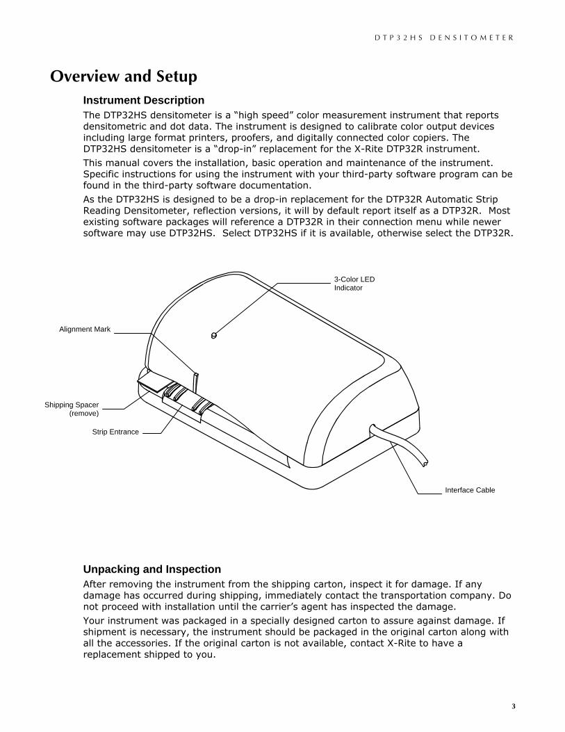
Overview and Setup Instrument Description The DTP32HS densitometer is a “high speed” color measurement instrument that reports densitometric and dot data. The instrument is designed to calibrate color output devices including large format printers, proofers, and digitally connected color copiers. The DTP32HS densitometer is a “drop-in” replacement for the X-Rite DTP32R instrument.
This manual covers the installation, basic operation and maintenance of the instrument. Specific instructions for using the instrument with your third-party software program can be found in the third-party software documentation.
As the DTP32HS is designed to be a drop-in replacement for the DTP32R Automatic Strip Reading Densitometer, reflection versions, it will by default report itself as a DTP32R. Most existing software packages will reference a DTP32R in their connection menu while newer software may use DTP32HS. Select DTP32HS if it is available, otherwise select the DTP32R.
Unpacking and Inspection After removing the instrument from the shipping carton, inspect it for damage. If any damage has occurred during shipping, immediately contact the transportation company. Do not proceed with installation until the carrier’s agent has inspected the damage.
Your instrument was packaged in a specially designed carton to assure against damage. If shipment is necessary, the instrument should be packaged in the original carton along with all the accessories. If the original carton is not available, contact X-Rite to have a replacement shipped to you.
Interface Cable
Alignment Mark
Shipping Spacer (remove)
3-Color LED Indicator
Strip Entrance
D T P 3 2 H S D E N S I T O M E T E R
4
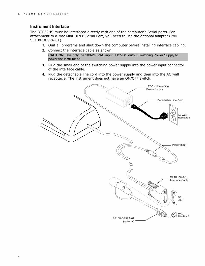
Instrument Interface The DTP32HS must be interfaced directly with one of the computer’s Serial ports. For attachment to a Mac Mini-DIN 8 Serial Port, you need to use the optional adapter (P/N SE108-DB9PA-01).
1. Quit all programs and shut down the computer before installing interface cabling.
2. Connect the interface cable as shown. CAUTION: Use only the 100-240VAC input, +12VDC output Switching Power Supply to power the instrument.
3. Plug the small end of the switching power supply into the power input connector of the interface cable.
4. Plug the detachable line cord into the power supply and then into the AC wall receptacle. The instrument does not have an ON/OFF switch.
PC DB9
AC Wall Receptacle
+12VDC Switching Power Supply
Detachable Line Cord
Power Input
SE108-97-02 Interface Cable
MAC Mini-DIN 8
SE108-DB9PA-01 (optional)
D T P 3 2 H S D E N S I T O M E T E R
5
Instrument Location Requirements To ensure reliable read switch activation, the instrument must sit on a reasonably flat, level, and stable surface.
Strip Feeding Requirements To ensure consistent strip readings, you must feed the strip into the instrument at a continual pace (without pausing) and speed before it is taken in by the drive motor. More specifically, a strip cannot be fed into the instrument too quickly (more than 7.2 inches/second or 183 mm/second), too slowly (less than 2.6 inches/second or 66 mm/second), or intermittently (pausing one or more times). If you are experiencing any strip-feeding problems, observe how fast the motor is moving the strip (about 5.4 inches/second or 137 mm/second) and try to match the speed as closely as possible.
Before feeding a second strip or a second pass of a multi-pass strip into the instrument, you must momentarily pause (approx. 3 seconds) to allow the instrument to process data from the first measurement. The LED is not lit when the instrument is processing data.
Instrument LED Indicator The LED indicates a variety of instrument operation conditions, such as calibration mode and operation. Below is a complete list of conditions reported by the LED.
Operation Mode • Solid Green—self-test passed and instrument is ready for use with defined strip.
• Slow Flashing Green—strip reading in progress (strip being read) or ready for next pass (multi-pass strip definition).
• Fast Flashing Green—strip reading was attempted but the wrong strip was read, or strip was skewed during reading.
• Slow Flashing Amber/Green—a configuration barcode was scanned and the instrument is waiting for the 2nd or 3rd barcode pass.
• Fast Flashing Amber/Green—there was an error in recognizing a barcode or the configuration failed. Reread the entire barcode, starting with the first pass.
Calibration Mode
• Slow Flashing Green—instrument calibration in progress (strip being read).
• Solid Green after Flashing Green—instrument calibration was successful and instrument is ready for use.
• Fast Flashing Green—instrument calibration failed.
Error/Reset Mode NOTE: When the instrument is first turned on, the motor runs, and the LED illuminates red while performing self-tests. Self-tests are completed in approximately 2 to 3 seconds, at which time the LED turns green and the motor stops under normal conditions.
• Fast Flashing Red—incorrect power supply attached. Verify correct 12-volt power supply is used.
• Slow Flashing Red—a factory reset is in progress.
• Flashing Red/Green— the host firmware loader program is reprogramming the instrument.
D T P 3 2 H S D E N S I T O M E T E R
6
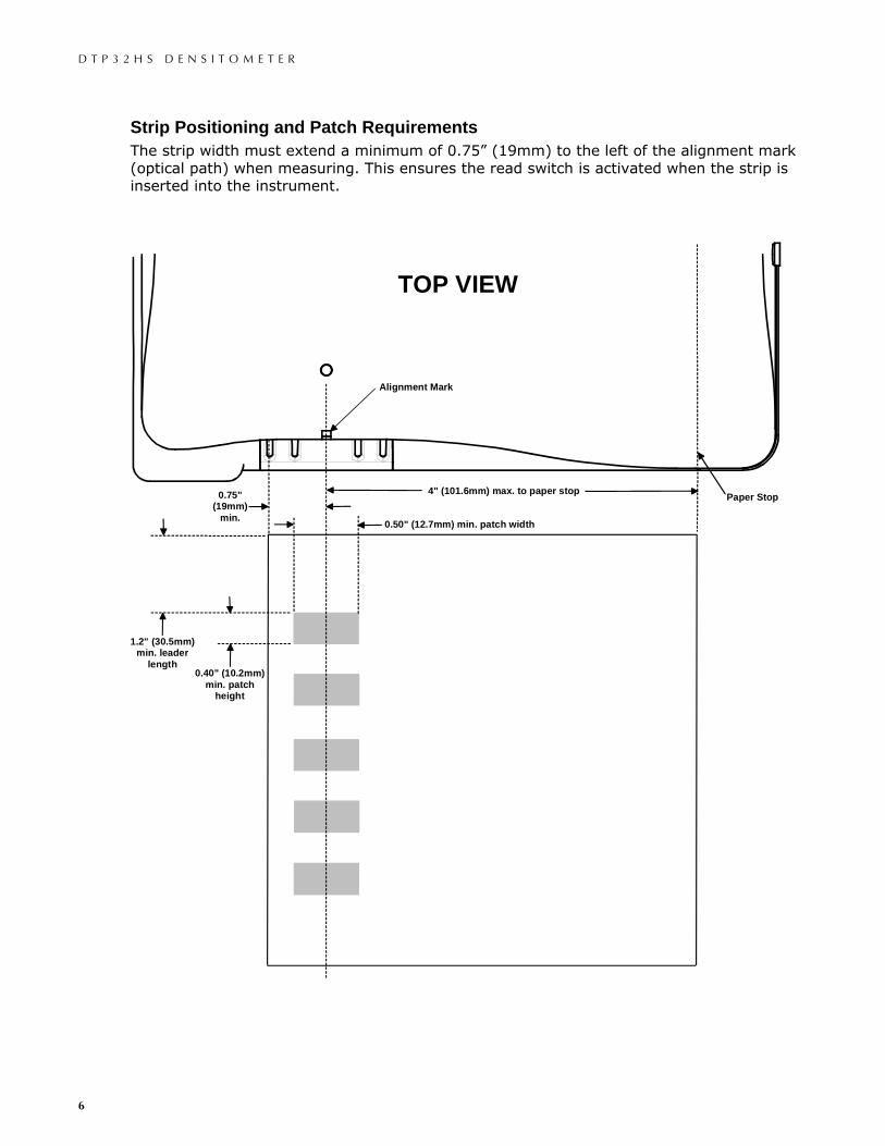
Strip Positioning and Patch Requirements The strip width must extend a minimum of 0.75” (19mm) to the left of the alignment mark (optical path) when measuring. This ensures the read switch is activated when the strip is inserted into the instrument.
TOP VIEW
0.75"(19mm)
min.
4" (101.6mm) max. to paper stop Paper Stop
Alignment Mark
0.50" (12.7mm) min. patch width
1.2" (30.5mm)min. leader
length0.40" (10.2mm)
min. patchheight
D T P 3 2 H S D E N S I T O M E T E R
7
Calibration Frequency of Calibration Your DTP32HS should be calibrated weekly. Refer to the following procedure for details on the calibration process.
Reflection Reference Handling Handle the reflection reference by the edges. Make sure that the reflection reference is free of dust, dirt and smudgemarks. Refer to General Maintenance Section for cleaning procedure. Always store the reflection reference in it protective envelope away from light and heat.
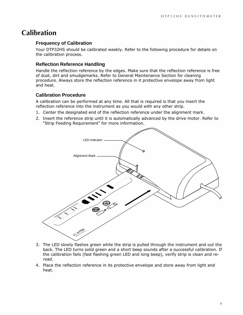
Calibration Procedure A calibration can be performed at any time. All that is required is that you insert the reflection reference into the instrument as you would with any other strip.
1. Center the designated end of the reflection reference under the alignment mark.
2. Insert the reference strip until it is automatically advanced by the drive motor. Refer to “Strip Feeding Requirement” for more information.
3. The LED slowly flashes green while the strip is pulled through the instrument and out the
back. The LED turns solid green and a short beep sounds after a successful calibration. If the calibration fails (fast flashing green LED and long beep), verify strip is clean and re-read.
4. Place the reflection reference in its protective envelope and store away from light and heat.
LED Indicator
Alignment Mark
D T P 3 2 H S D E N S I T O M E T E R
8
Strip Measurement Important Notes • You should refer to the documentation for the software program that you are using with
your instrument. All applications that utilize this instrument must be running during measurements.
• The strip must have at least a 1.2″ (30.5mm) leader before the leading edge of the first step. Contact X-Rite Applications Support if additional information is required. Inspect the strip for spots or defects on the steps. Defects may cause inaccurate measurements.
• The darkest patch of a strip must be read first unless there is at least 1.1″ (27.9mm) unprinted trailer after the last patch.
• Some software packages define strips as “multi-pass” where all color passes must be read before a conformation is displayed on the monitor. In these cases, a successful reading of a color pass is shown by the instrument slowly flashing green after the reading. This indicates that you may continue to the next color pass. Fast flashing of green indicates a re-read is required on the pass. The instrument’s LED will stay at solid green after all passes are successfully read.
Strip Positioning and Measurement Techniques The following information is provided to familiarize you with reading strips, a series of printed control patches.
1. Select strip type to measure from the host software.
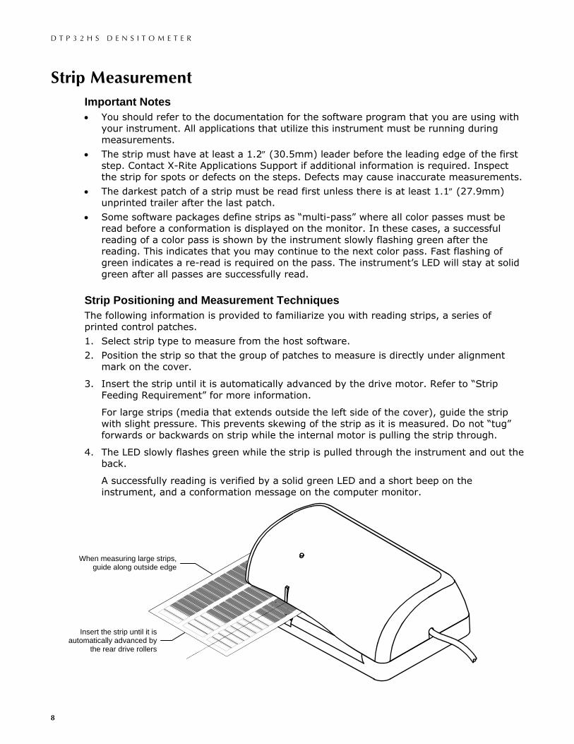
2. Position the strip so that the group of patches to measure is directly under alignment mark on the cover.
3. Insert the strip until it is automatically advanced by the drive motor. Refer to “Strip Feeding Requirement” for more information.
For large strips (media that extends outside the left side of the cover), guide the strip with slight pressure. This prevents skewing of the strip as it is measured. Do not “tug” forwards or backwards on strip while the internal motor is pulling the strip through.
4. The LED slowly flashes green while the strip is pulled through the instrument and out the back.
A successfully reading is verified by a solid green LED and a short beep on the instrument, and a conformation message on the computer monitor.
Insert the strip until it is automatically advanced by
the rear drive rollers
When measuring large strips, guide along outside edge
D T P 3 2 H S D E N S I T O M E T E R
9
Troubleshooting, Service, and General Maintenance Troubleshooting The DTP32HS is used with a number of third party software vendors. To get the most specialized technical assistance, you should first contact the technical service representative for the specific third-party software that you are using.
Prior to contacting X-Rite, Inc. Customer Service for instrument problems try the applicable solution(s) described below. If the condition persists, contact a Customer Service Representative toll-free by phone at: 1-888-826-3059; or by fax at: 1-888-826-3061. You can also contact X-Rite’s support staff through our Support page at www.xrite.com.
LED not lit: • Ensure that the power supply is plugged in and connected to the Interface Cable.
• Reset the instrument (see Instrument Reset).
Fast flashing green LED:
• If error persists, clean instrument and calibration strip (see General Cleaning).
• Reset the instrument (see Instrument Reset).
Solid red LED: • Remove power from the instrument, reapply power and see if the condition is corrected.
• Reset the instrument (see Instrument Reset) and calibrate.
• This could indicate that the unit may not be programmed properly, which could happen if power was removed during reprogramming. Try reprogramming the instrument again (refer to the programming instructions that came with your update).
Densitometer and software not communicating:
• Verify that the instruments LED indicates normal operation (see Instrument LED Indicator). If normal, close and restart the software application. If this does not work reboot the computer.
• Remove power from the instrument, reapply power and see if the condition is corrected.
• Check for proper configuration setting from the software provider.
• Reset the instrument (see Instrument Reset) and calibrate.
Repeated strip measurement failures:
• Ensure that the strip is being read in accordance with your software’s documentation.
• Close and restart the software application.
• Perform a calibration on the instrument (see Calibration section).
• Reset the instrument (see Instrument Reset).
Repeated calibration failures: • Clean instrument and reference (see General Maintenance).
• Strip definition set below five steps.
• Reset the instrument (see Instrument Reset) and calibrate.
Reading lamp not working:
• When the temperature in the optics area reaches or exceeds 45°C (or 113°F), the instrument will keep the reading lamp from turning on. This is to prevent any damage from occurring to the optics components. Allow the instrument to cool before measuring.
• Reset the instrument (see Instrument Reset).
D T P 3 2 H S D E N S I T O M E T E R
10
Service Information The DTP32HS Densitometer is covered by a one-year limited warranty and should be referred to an authorized service center for repairs within the warranty period.
X-Rite provides repair service to their customers. Because of the complexity of the circuitry, all repairs should be referred to an authorized service center.
X-Rite will repair any instrument past warranty. The customer shall pay shipping and repair cost to the authorized service center, and the instrument shall be submitted in the original carton, as a complete unaltered unit along with all the supplied accessories.
General Maintenance Your instrument requires very little maintenance to achieve years of reliable operation. However, to protect your investment and maintain reading accuracy, a few simple-cleaning procedures should be performed from time to time.
General Cleaning Whenever required, the exterior of the instrument may be wiped clean with a cloth dampened in water or mild cleaner. NOTE: DO NOT use any solvents to the clean the instrument, this will cause damage to the cover.
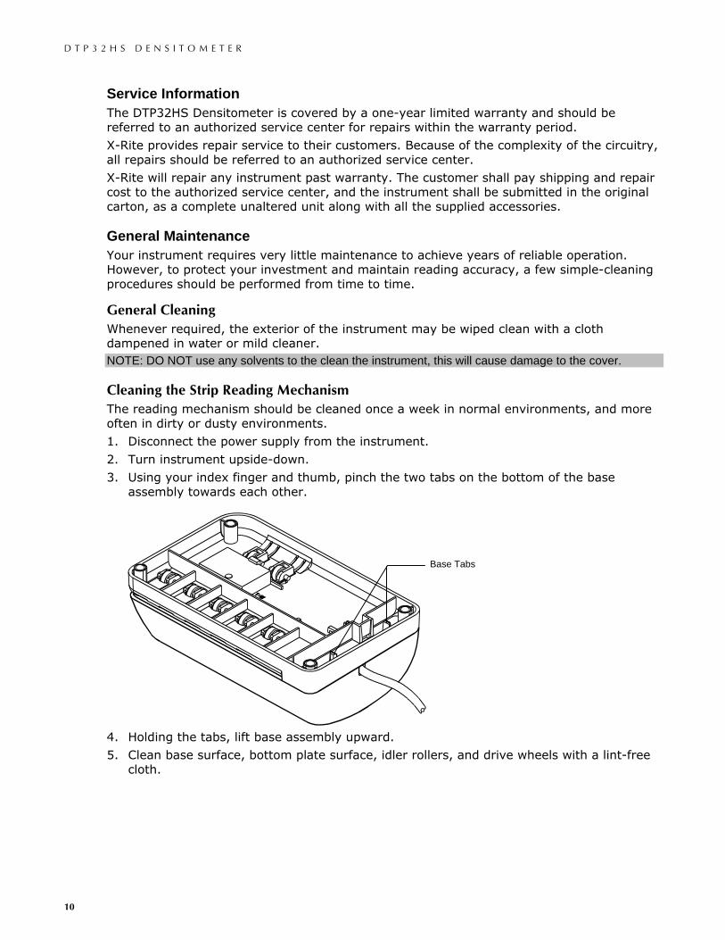
Cleaning the Strip Reading Mechanism The reading mechanism should be cleaned once a week in normal environments, and more often in dirty or dusty environments.
1. Disconnect the power supply from the instrument.
2. Turn instrument upside-down.
3. Using your index finger and thumb, pinch the two tabs on the bottom of the base assembly towards each other.
4. Holding the tabs, lift base assembly upward.
5. Clean base surface, bottom plate surface, idler rollers, and drive wheels with a lint-free cloth.
Base Tabs
D T P 3 2 H S D E N S I T O M E T E R
11
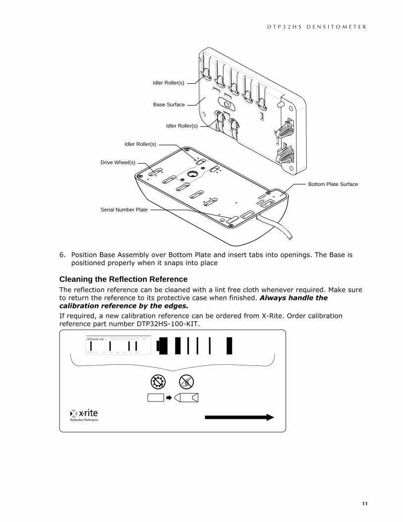
6. Position Base Assembly over Bottom Plate and insert tabs into openings. The Base is positioned properly when it snaps into place
Cleaning the Reflection Reference The reflection reference can be cleaned with a lint free cloth whenever required. Make sure to return the reference to its protective case when finished. Always handle the calibration reference by the edges.
If required, a new calibration reference can be ordered from X-Rite. Order calibration reference part number DTP32HS-100-KIT.
Idler Roller(s)
Base Surface
Idler Roller(s)
Idler Roller(s)
Drive Wheel(s)
Bottom Plate Surface
Serial Number Plate
D T P 3 2 H S D E N S I T O M E T E R
12
Technical Information Instrument Reset Note: When performing an Instrument Reset, which restores the X-Rite Factory Defaults, you will have to ensure the correct configuration for your software is then restored.
The following procedure resets DTP32HS to the factory default settings.
1. Disconnect power from the instrument.
2. Insert a piece of paper or a strip into the instrument past the front idler rollers.
3. Reapply power to the instrument.
4. After the LED begins to flash red slowly, remove the paper The factory defaults are now reinstated.
Drive Wheels Rotation Timer The instruments rubber drive wheels may develop temporary flat spots if the instrument sits idle for and extended period of time. These “flat spots” could cause the first few moments of a reading to contain unwanted noise. To prevent this condition, the instrument incorporates an automatic timer that rotates the drive wheels for 10 seconds after a 12 hour, non-use period. A reading or computer command that occurs during a wheel rotation timer cycle will override the cycle and the clock resets.
Technical Notes Firmware Update After updating the instrument firmware you must power down the instrument and then power it back up. This ensures that the instrument functions properly and user-configurable settings are restored to the factory defaults.
Calibration Strip The number of steps in the strip definition must be set to a minimum of five to achieve a successful calibration using the X-Rite calibration reference strip.
D T P 3 2 H S D E N S I T O M E T E R
13
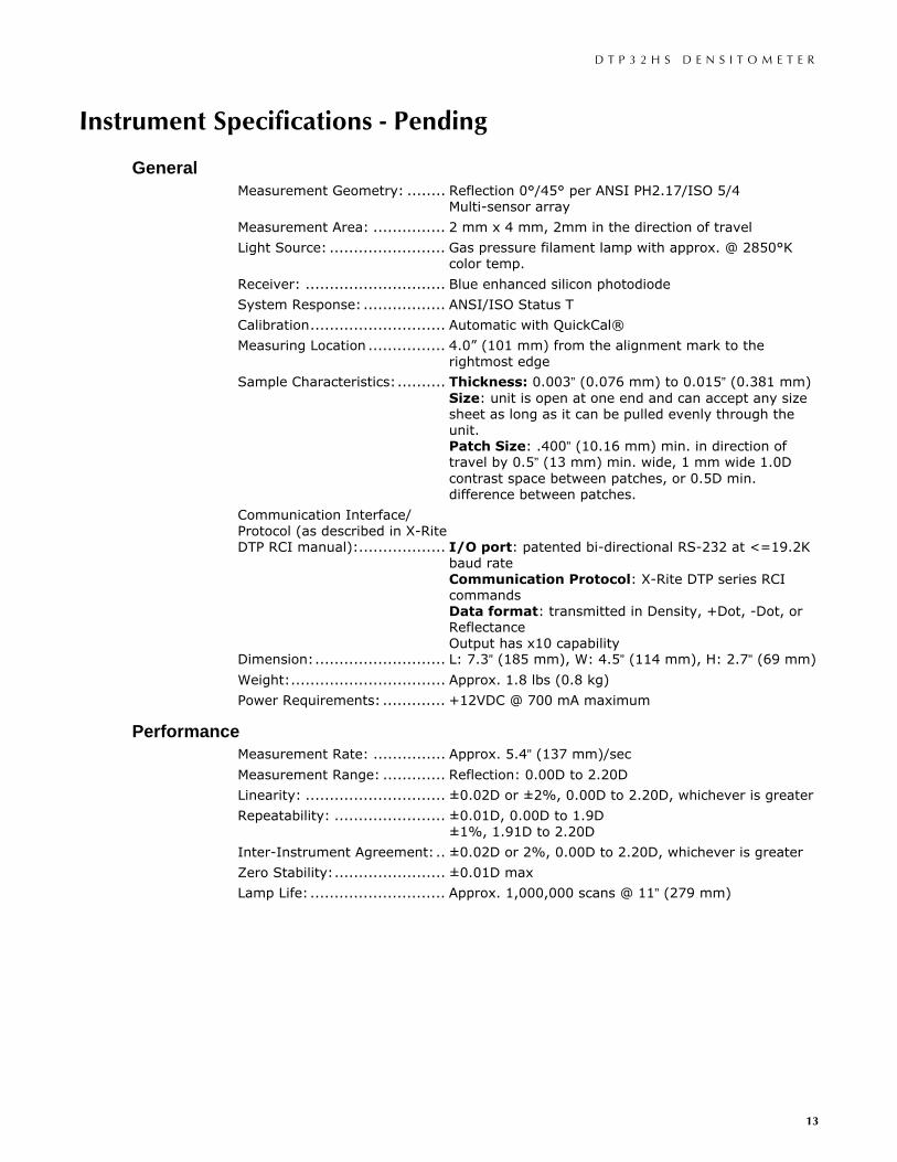
Instrument Specifications - Pending
General Measurement Geometry: ........ Reflection 0°/45° per ANSI PH2.17/ISO 5/4
Multi-sensor array
Measurement Area: ............... 2 mm x 4 mm, 2mm in the direction of travel
Light Source: ........................ Gas pressure filament lamp with approx. @ 2850°K color temp.
Receiver: ............................. Blue enhanced silicon photodiode
System Response: ................. ANSI/ISO Status T
Calibration............................ Automatic with QuickCal®
Measuring Location ................ 4.0” (101 mm) from the alignment mark to the rightmost edge
Sample Characteristics:.......... Thickness: 0.003” (0.076 mm) to 0.015” (0.381 mm) Size: unit is open at one end and can accept any size sheet as long as it can be pulled evenly through the unit. Patch Size: .400” (10.16 mm) min. in direction of travel by 0.5” (13 mm) min. wide, 1 mm wide 1.0D contrast space between patches, or 0.5D min. difference between patches.
Communication Interface/ Protocol (as described in X-Rite DTP RCI manual):.................. I/O port: patented bi-directional RS-232 at <=19.2K
baud rate Communication Protocol: X-Rite DTP series RCI commands Data format: transmitted in Density, +Dot, -Dot, or Reflectance Output has x10 capability
Dimension:........................... L: 7.3” (185 mm), W: 4.5” (114 mm), H: 2.7” (69 mm)
Weight:................................ Approx. 1.8 lbs (0.8 kg)
Power Requirements: ............. +12VDC @ 700 mA maximum
Performance Measurement Rate: ............... Approx. 5.4” (137 mm)/sec
Measurement Range: ............. Reflection: 0.00D to 2.20D
Linearity: ............................. ±0.02D or ±2%, 0.00D to 2.20D, whichever is greater
Repeatability: ....................... ±0.01D, 0.00D to 1.9D ±1%, 1.91D to 2.20D
Inter-Instrument Agreement:.. ±0.02D or 2%, 0.00D to 2.20D, whichever is greater
Zero Stability:....................... ±0.01D max
Lamp Life: ............................ Approx. 1,000,000 scans @ 11” (279 mm)
D T P 3 2 H S D E N S I T O M E T E R
14
Environmental Operating Temp: ................... 10° to 35°C
Storage Temp:...................... -40° to 45°C
Humidity Range: ................... 0 - 85% RH
Usage:................................. Indoor Only
Altitude:............................... 2000m
Pollution Degree:................... 2
Transient Overvoltage:........... Category II
Safety Compliance Underwriters Laboratories:...... UL 61010-1
Canadian Standards Association: CSA 22.2 No. 1010.1-92
CENELEC.............................. IEC (EN) 61010-1
Design and specifications subject to change without notice.
Standard Accessories Calibration Reference
DTP Series CD
Serial Communication Cable (integrated with the instrument)
+12VDC Switching Power Supply
Line Cord (North America)
Line Cord (Europe)
Optional Accessories Mac Serial Adapter ............ P/N SE108-DB9PA-01
25-pin Serial Adapter......... P/N SE108-231-01
D T P 3 2 H S D E N S I T O M E T E R
15
Operational Considerations Between a DTP32R and a DTP32HS
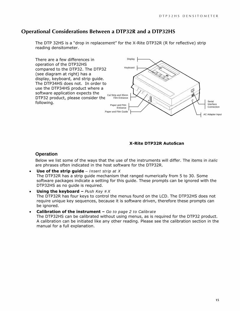
The DTP 32HS is a “drop in replacement” for the X-Rite DTP32R (R for reflective) strip reading densitometer.
There are a few differences in operation of the DTP32HS compared to the DTP32. The DTP32 (see diagram at right) has a display, keyboard, and strip guide. The DTP34HS does not. In order to use the DTP34HS product where a software application expects the DTP32 product, please consider the following.
Operation Below we list some of the ways that the use of the instruments will differ. The items in italic are phrases often indicated in the host software for the DTP32R.
• Use of the strip guide – Insert strip at X The DTP32R has a strip guide mechanism that ranged numerically from 5 to 30. Some software packages indicate a setting for this guide. These prompts can be ignored with the DTP32HS as no guide is required.
• Using the keyboard – Push Key #X The DTP32R has four keys to control the menus found on the LCD. The DTP32HS does not require unique key sequences, because it is software driven, therefore these prompts can be ignored.
• Calibration of the instrument – Go to page 2 to Calibrate The DTP32HS can be calibrated without using menus, as is required for the DTP32 product. A calibration can be initiated like any other reading. Please see the calibration section in the manual for a full explanation.
X-Rite DTP32R AutoScan
Paper and Film Entrance
Cal Strip and 35mm Film Entrance
Paper and Film Guide
Keyboard
Display
AC Adapter Input
Serial Interface Connection
D T P 3 2 H S D E N S I T O M E T E R
16
Barcode Operation You can change several configuration settings of your DTP32HS Densitometer using the special format barcodes supplied in this document or by your software provider. These set-up barcodes consist of multiple strips that must be read in the proper order.
In most cases your software will automatically configure your instrument. If your software or software documentation prompts you to configure your instrument, the enclosed X-Rite Set-up Barcodes contain some commonly used commands that can be scanned immediately to get you up and running. Additional barcode set-up and information is available on the CD that is shipped with your instrument.
The LEDs signal the status of the instrument when reading a set-up barcode. While scanning the initial barcode, the LEDs will flash slowly between off and green, the same as any normal scan. Once the unit has recognized the initial barcode as being part of a set-up barcode, the LEDs will slowly flash between amber and green. This same flash pattern will continue while scanning continuation barcodes. Upon completion of the entire set-up barcode, the LEDs will come on steady green, indicating a successful completion.
REFER TO THE FOLLOWING PAGES FOR X-RITE SET-UP BARCODES.
CAUTION: Only use the Set-up barcodes if instructed to manually set-up your instrument. This will avoid changing configurations that may cause the densitometer and your software to cease communicating. If this does happen reference the Troubleshooting, Service, and General Maintenance section.
NOTE: To enable the following barcodes to print at their intended size, make sure the following print option is set correctly in the Print dialog for your particular version of Adobe Reader.
• Reader version 6 Set “Page Scaling” to “None”
• Reader version 5 Disable (un-check) “Shrink oversize pages to paper size” check box
• Reader version 3 or 4 Disable (un-check) “Fit to Page” check box
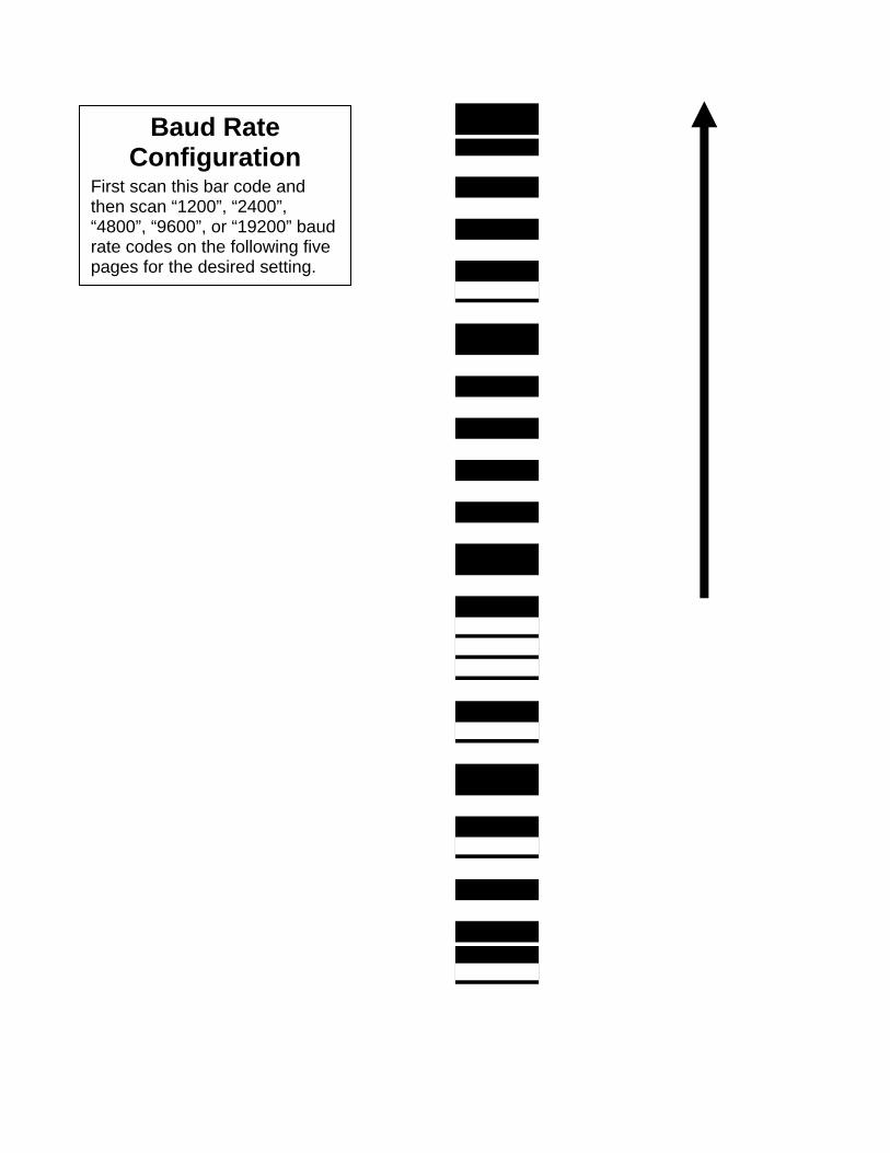
Baud Rate Configuration
First scan this bar code and then scan “1200”, “2400”, “4800”, “9600”, or “19200” baud rate codes on the following five pages for the desired setting.
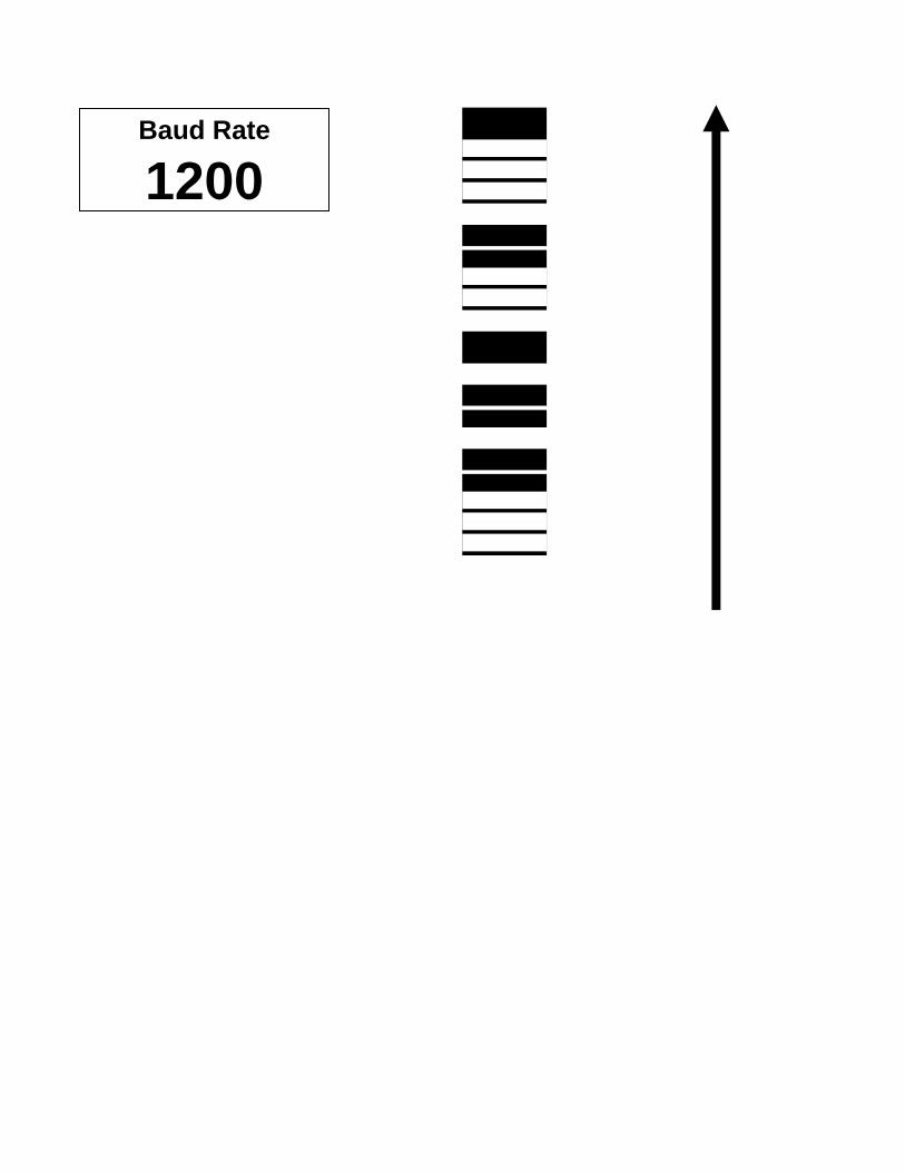
Baud Rate
1200
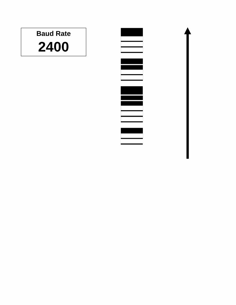
Baud Rate
2400
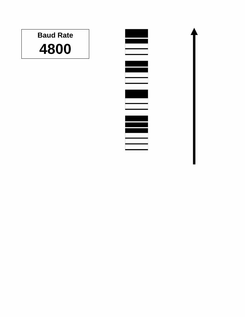
Baud Rate
4800
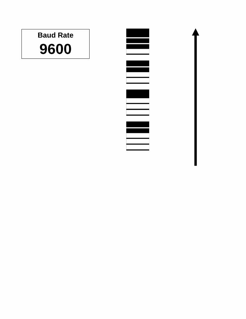
Baud Rate
9600
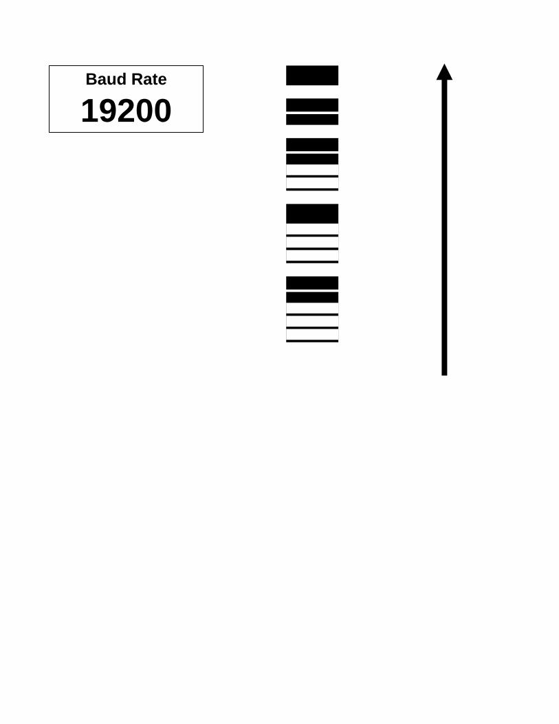
Baud Rate
19200

Auto Transmit Configuration
First scan this bar code and then scan the “On” or “Off” code on the following two pages for the desired setting.

Auto Transmit
On
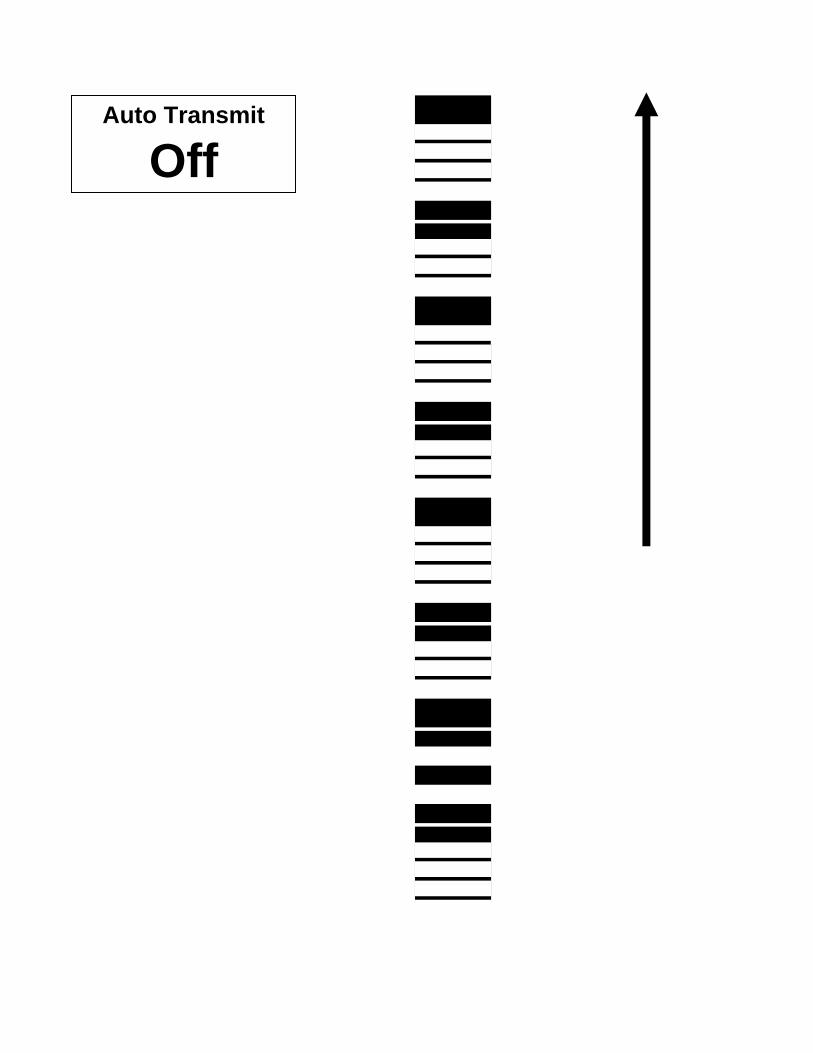
Auto Transmit
Off

Decimal Point Configuration
First scan this bar code and then scan the “On” or “Off” code on the following two pages for the desired setting.
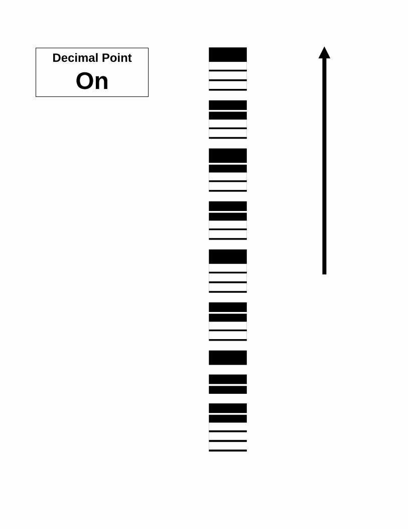
Decimal Point
On

Decimal Point
Off

Times Ten Configuration
First scan this bar code and then scan the “On” or “Off” code on the following two pages for the desired setting.
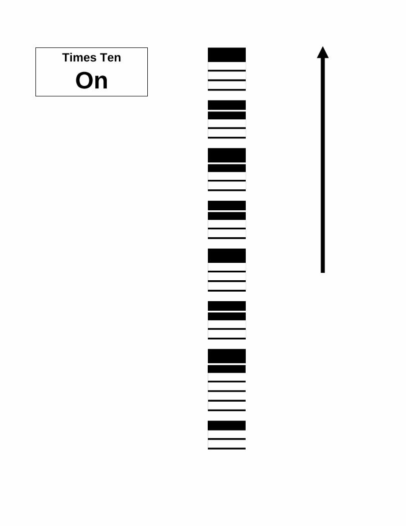
Times Ten
On
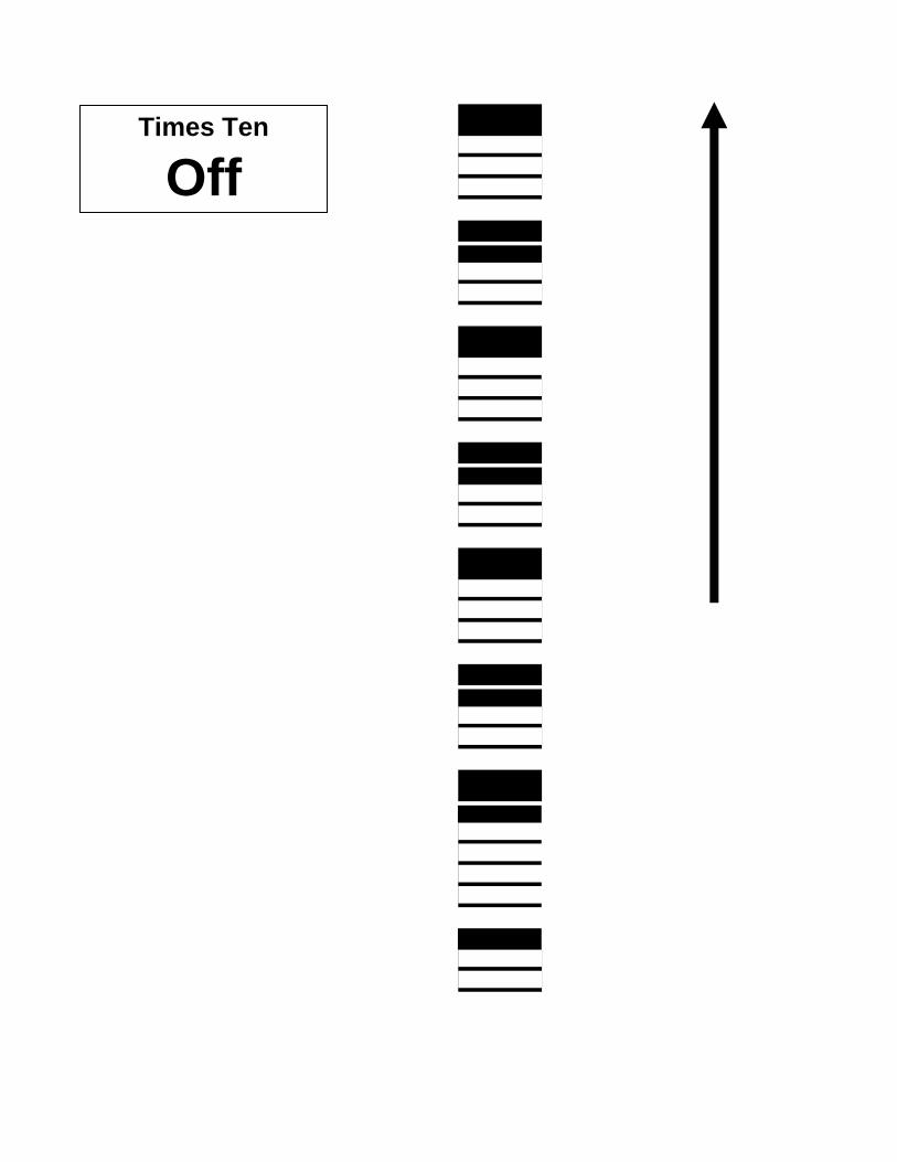
Times Ten
Off
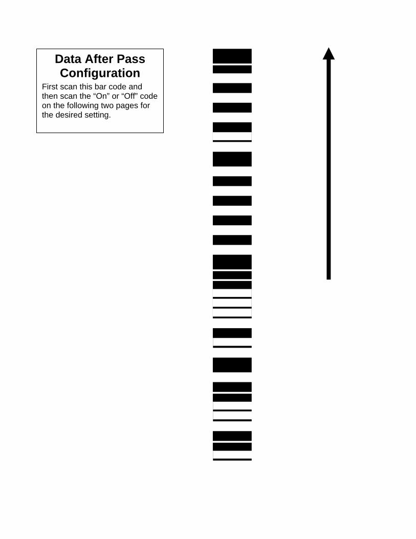
Data After Pass Configuration
First scan this bar code and then scan the “On” or “Off” code on the following two pages for the desired setting.

Data After Pass
On
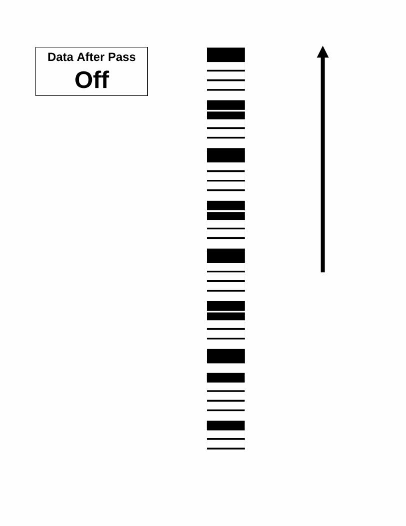
Data After Pass
Off
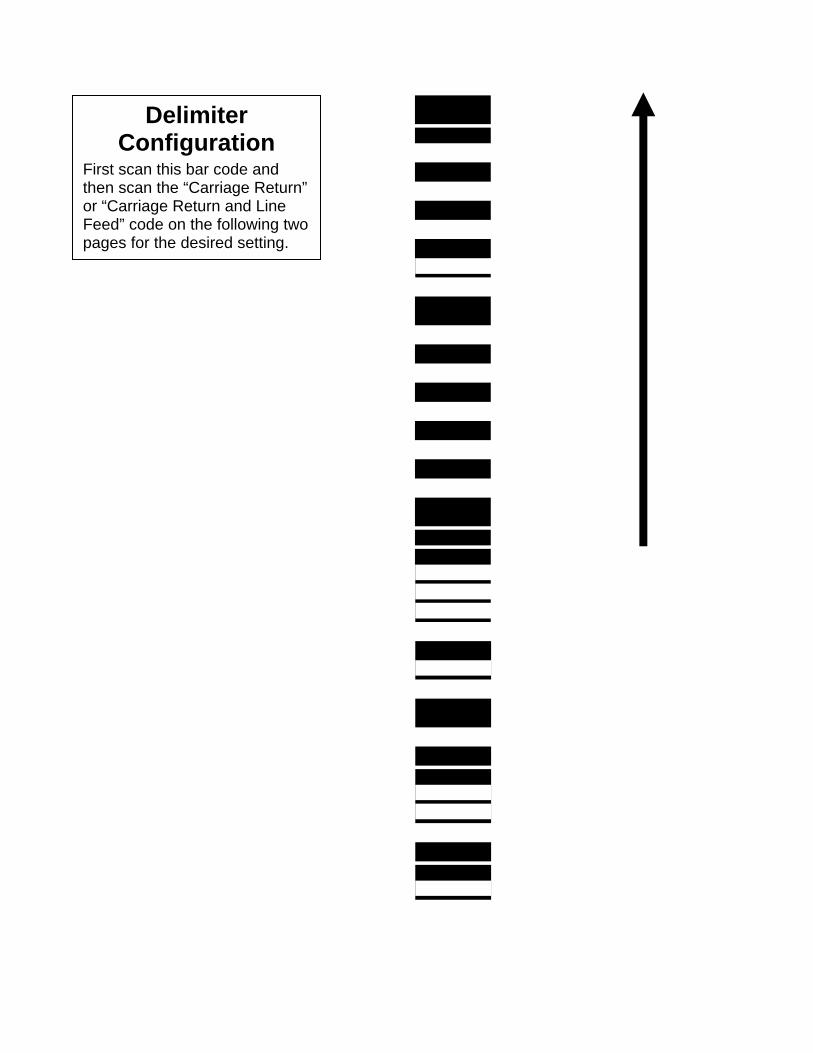
Delimiter Configuration
First scan this bar code and then scan the “Carriage Return” or “Carriage Return and Line Feed” code on the following two pages for the desired setting.
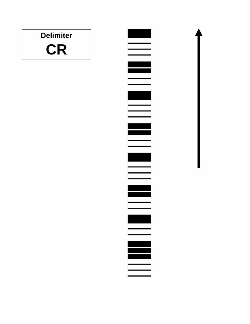
Delimiter
CR
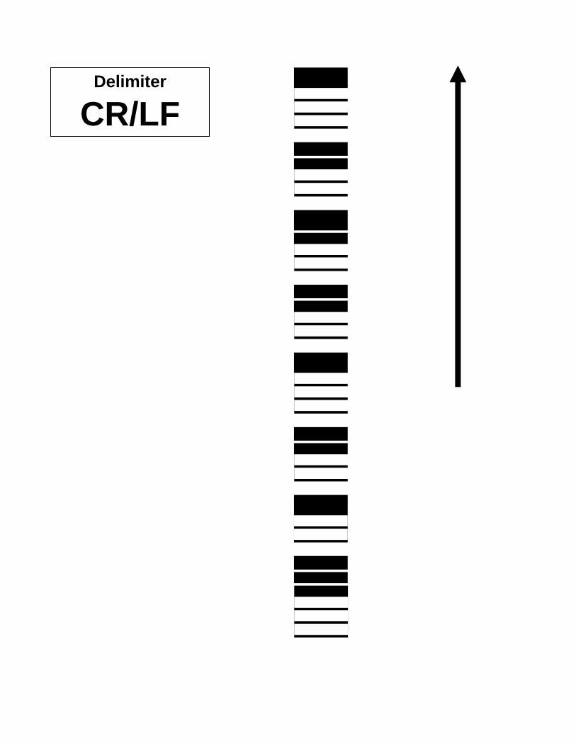
Delimiter
CR/LF
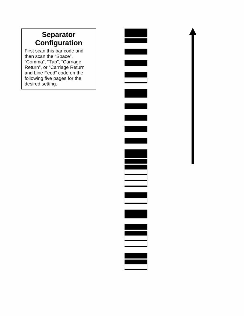
Separator Configuration
First scan this bar code and then scan the “Space”, “Comma”, “Tab”, “Carriage Return”, or “Carriage Return and Line Feed” code on the following five pages for the desired setting.
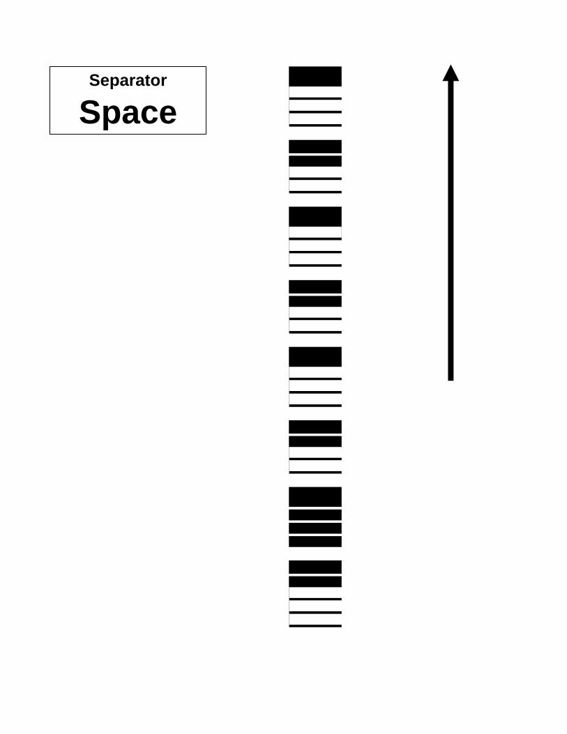
Separator
Space
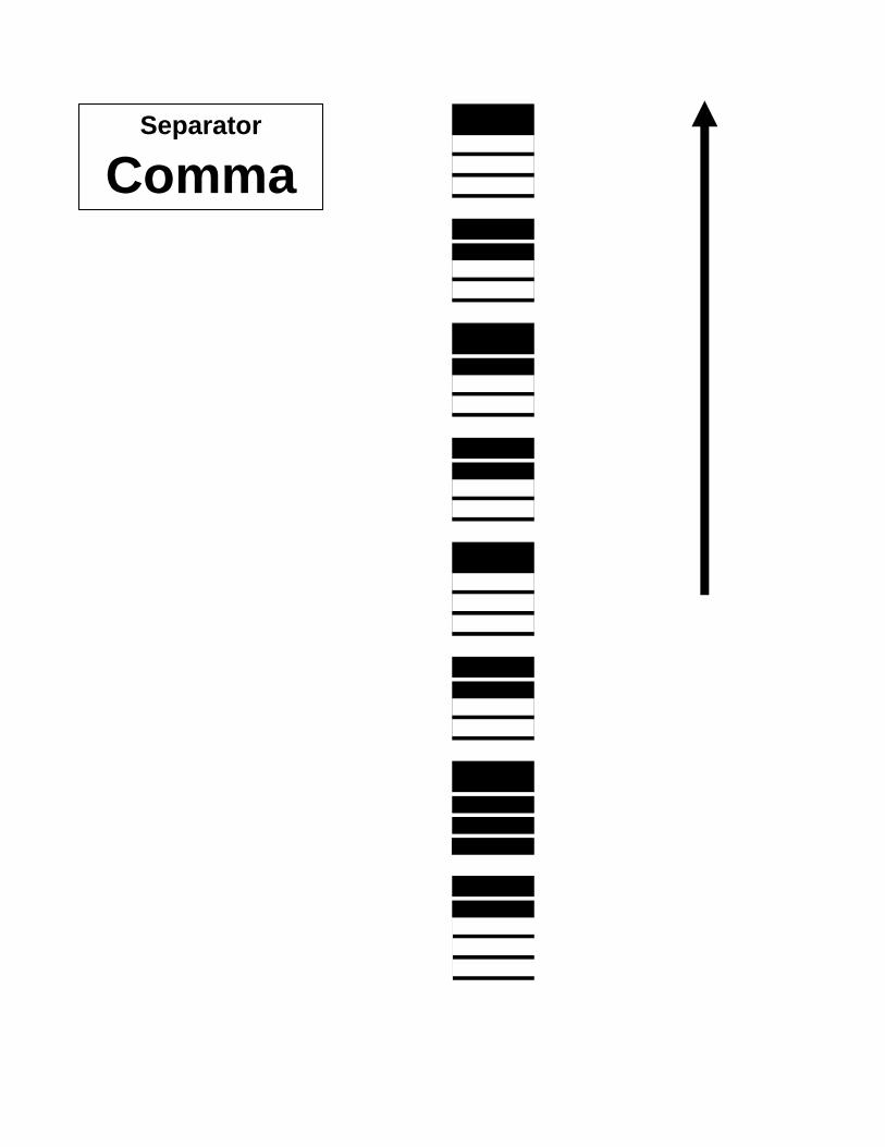
Separator
Comma
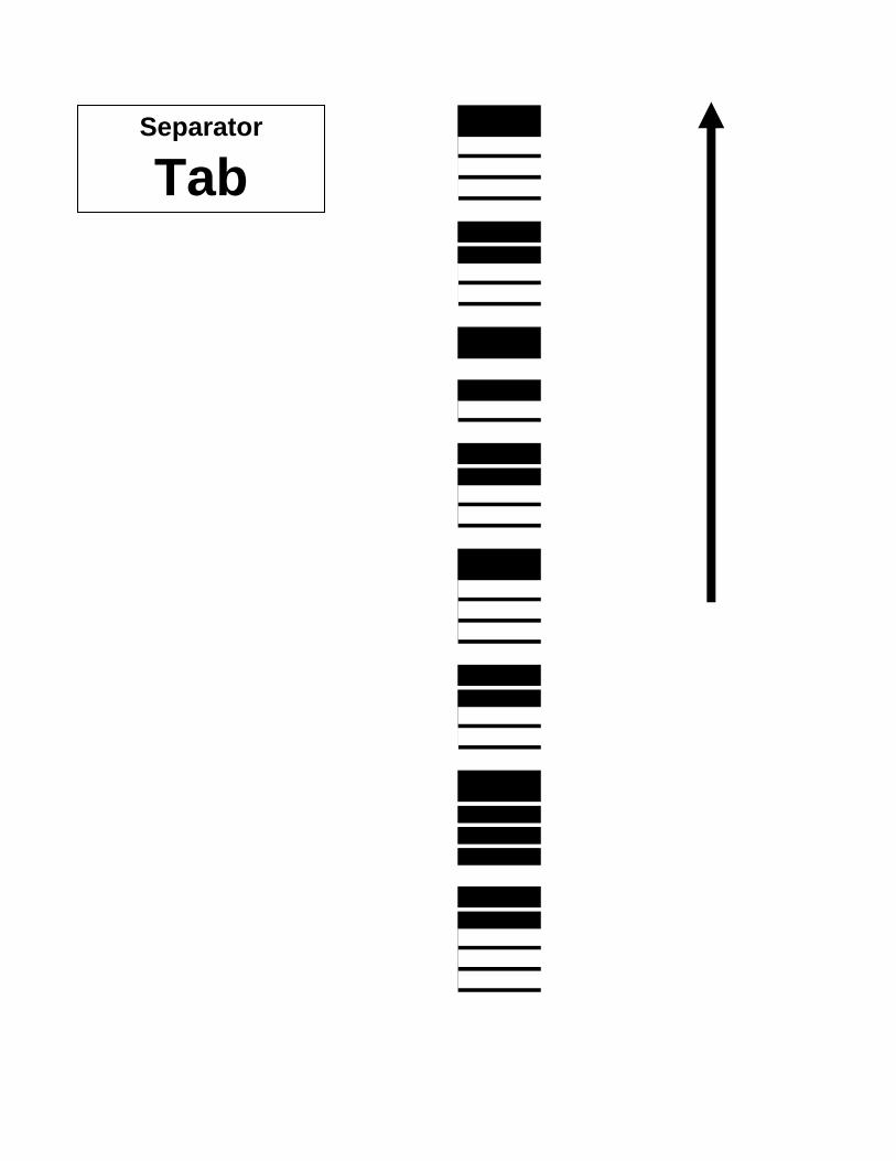
Separator
Tab
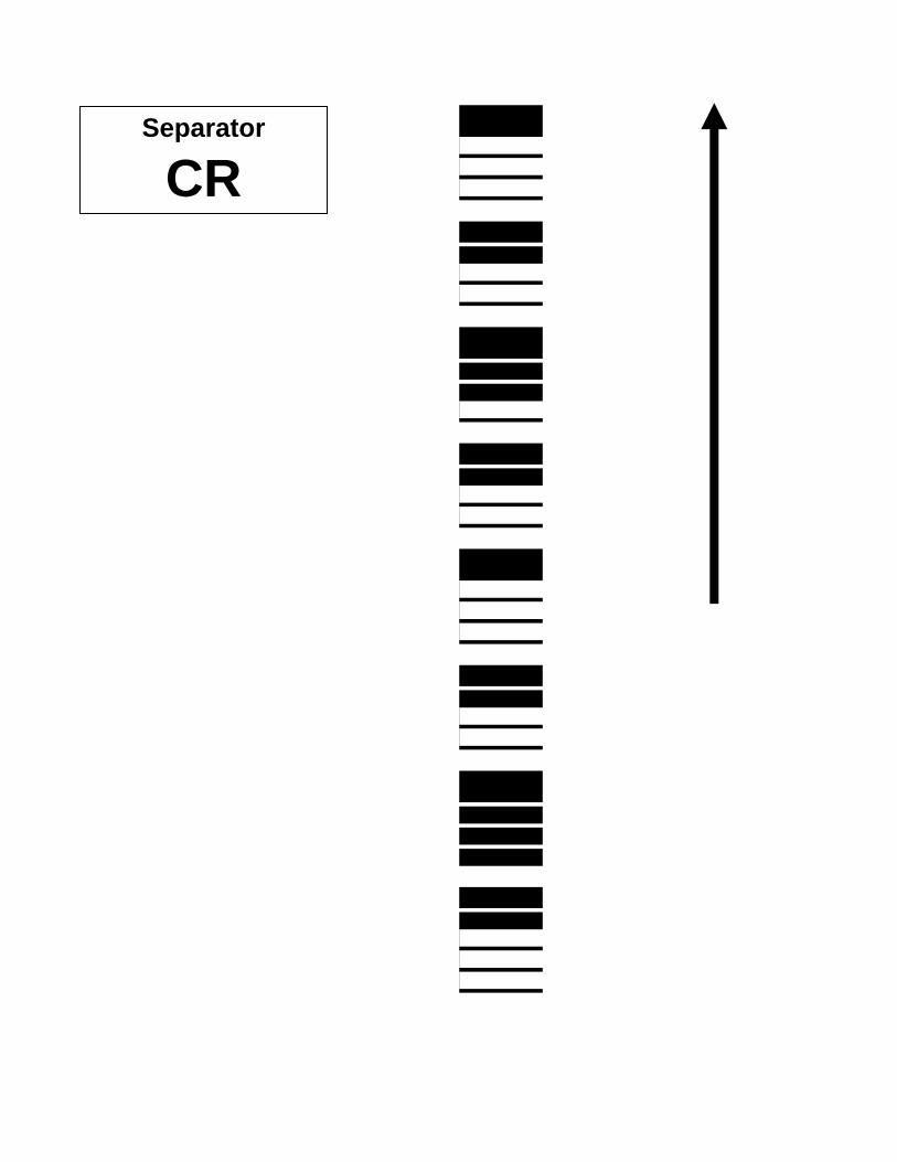
Separator
CR

Separator
CR/LF

Min/Max Configuration
First scan this bar code and then scan the “Off”, “Min”, “Max”, or “Min and Max” code on the following four pages for the desired setting.
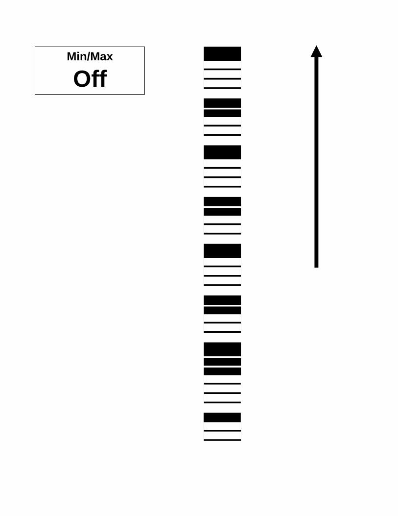
Min/Max
Off
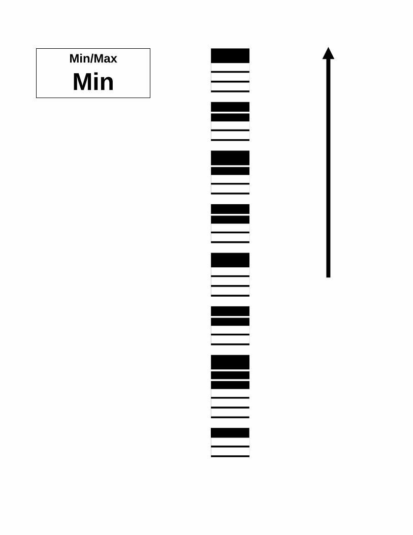
Min/Max
Min

Min/Max
Max
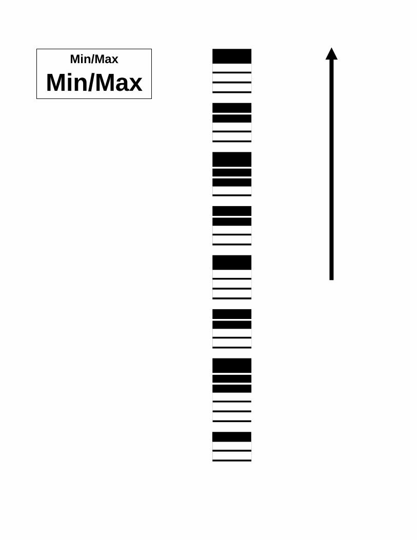
Min/Max
Min/Max


X-Rite, Incorporated - World Headquarters 3100 44th Street S.W. • Grandville, Michigan 49418 • USA www.x-rite.com Tel: 1-888-826-3059 • Fax: 1-888-826-3061 or (616) 534-0726 International Numbers Tel: 1-888-826-3039 or (616) 534-7663 • Fax: (616) 534-0723 X-Rite GmbH Stollwerckstraße 32 • 51149 Köln • Germany Tel: (49) 22 03 – 91 45-0 • Fax: (49) 22 03 – 91 45-19 X-Rite GmbH Sochorova 705 • CZ-682 • 11 Vyskov • Czech Republic Tel: (420) 507-328197 • Fax: (420) 507-328138 X-Rite Asia Pacific Ltd. Room 808-10 • Kornhill Metro Tower • 1 Kornhill Road • Quarry Bay Hong Kong • Tel: (852) 2-568-6283 • Fax: (852) 2-885-8610 X-Rite Ltd. The Acumen Centre • First Avenue Poynton, Cheshire • England Tel: 44-0-1625-871100 • Fax: 44-0-1625-871444 X-Rite Méditerranée Parc du moulin de Massy • 35, rue du Saule Trapu • 91300 Massy • France Tel: 33-1-69.53.66.20 • FAX 33-1-69.53.00.52 X-Rite Italy Srl Via per Caronno, 35 21040 Origgio (Va) • Italy Tel. 0039 02 96734266 • Fax. 0039 02 96730681 X-Rite Asia Pacific Ltd. - Japan Office No.1 Baba Bldg. • 3-19-18 Shibaura, Minato-ku, Tokyo • 108-0023 Japan Tel: +81-3-5439-5971 • Fax: +81-3-5439-5972 X-Rite Asia Pacific Ltd. - Singapore Representative Office 14 Science Park Drive • #02-04 The Maxwell Singapore Science Park • Singapore 118226 Tel: + 65 7788-773 • Fax: + 65 7788-645
P/N DTP32HS-500 Rev. A-12/18/03