auto-restoration data translation application · auto-restoration data translation application...
TRANSCRIPT

g Digital Energy
Document Number : PRPI-024 Version : 2.00
Revision : 2 Date : 03.02.10
Classification: General Full
Auto-Restoration Data Translation Application Product Description, Information and Specification

Auto-Restoration Data Translation Application Product Description, Information and Specification
PRPI-024-2.00-2 General
ii Full
NOTICE OF COPYRIGHT & PROPRIETARY RIGHTS
© 2003, General Electric Canada Inc. All rights reserved.
The contents of this manual are the property of General Electric Canada Inc. No part of this work may be reproduced or transmitted in any form or by any means, except as permitted in written license agreement with General Electric Canada Inc. The information contained in this document is subject to change without notice.
Any attached hardware schematics and technical descriptions, or software listings that disclose source code, are for information purposes only. Reproduction in whole or in part to create working hardware or software for other than General Electric Canada Inc. products is strictly prohibited, except as permitted by written license agreement with General Electric Canada Inc.
TRADEMARK NOTICES
GE and g are trademarks and service marks of General Electric Company.
WESDAC is a registered trademark of General Electric Company, General Electric Canada Inc. All other brand and product names mentioned in this document are trademarks or registered trademarks of their respective companies.
Auto-Restoration Data Translation Application Product Description, Information and Specification
General PRPI-024-2.00-2 Full iii
Table of Contents
Introduction
Purpose of this Document .......................................................................................................... ix Distribution of the Document..................................................................................................... ix Control of this Document........................................................................................................... ix Related Documents ..................................................................................................................... x
Product Background
Chapter 1: Product Information
1.1 Features of the AR Application....................................................................................... 1 1.2 Compatibility of the AR Application .............................................................................. 3
1.2.1 Hardware Compatibility.............................................................................................. 3 1.2.2 Software Compatibility ............................................................................................... 3 1.2.3 Documentation ............................................................................................................ 3 1.2.4 Utility Environment Compatibility ............................................................................. 4
1.3 Ordering the AR Application .......................................................................................... 4
Chapter 2: Product Description
2.1 Overview ......................................................................................................................... 5 2.2 System Perspective.......................................................................................................... 6 2.3 Description of Algorithm ................................................................................................ 9
2.3.1 Initialization ................................................................................................................ 9 2.3.2 Restoration Qualification ............................................................................................ 9 2.3.3 Load Restoration ....................................................................................................... 10
2.4 Substation Breaker Data................................................................................................ 11 2.5 AR Application from the Operator’s Viewpoint........................................................... 12 2.6 Configurable Parameters ............................................................................................... 13

Auto-Restoration Data Translation Application Product Description, Information and Specification
PRPI-024-2.00-2 General
iv Full
2.6.1 Global Parameters ..................................................................................................... 13 2.6.2 Group Parameters...................................................................................................... 13 2.6.3 Breaker Parameters ................................................................................................... 13 2.6.4 Switch Parameters ..................................................................................................... 13
2.7 AR Application System Points...................................................................................... 14 2.8 Configuring an AR System ........................................................................................... 14 2.9 Performance of the AR Application.............................................................................. 14

Auto-Restoration Data Translation Application Product Description, Information and Specification
General PRPI-024-2.00-2 Full v
List of Figures
Figure 1 Example Feeder Configuration........................................................................................ 6
Figure 2 Auto-Restoration System Context ................................................................................... 7
Figure 3 System Software Interfaces ............................................................................................. 8
Figure 4 Breaker Signature .......................................................................................................... 11

Auto-Restoration Data Translation Application Product Description, Information and Specification
PRPI-024-2.00-2 General
vi Full
Auto-Restoration Data Translation Application Product Description, Information and Specification
General PRPI-024-2.00-2 Full vii
List of Tables
Table 1 Table Name ..................................................................................................................... 14

Auto-Restoration Data Translation Application Product Description, Information and Specification
PRPI-024-2.00-2 General
viii Full
General PRPI-024-2.00-2 Full ix
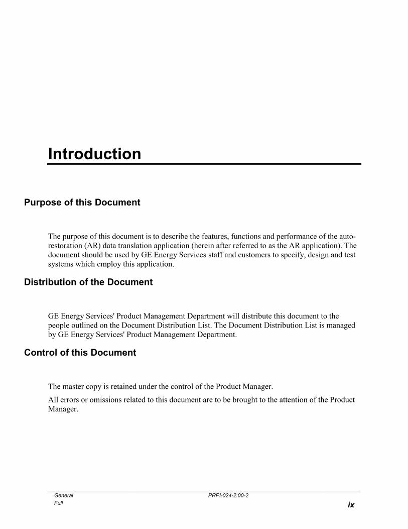
Introduction
Purpose of this Document
The purpose of this document is to describe the features, functions and performance of the auto-restoration (AR) data translation application (herein after referred to as the AR application). The document should be used by GE Energy Services staff and customers to specify, design and test systems which employ this application.
Distribution of the Document
GE Energy Services' Product Management Department will distribute this document to the people outlined on the Document Distribution List. The Document Distribution List is managed by GE Energy Services' Product Management Department.
Control of this Document
The master copy is retained under the control of the Product Manager.
All errors or omissions related to this document are to be brought to the attention of the Product Manager.

Auto-Restoration Data Translation Application Product Description, Information and Specification
PRPI-024-2.00-2 General
x Full
Related Documents
Auto-Sectionalizing Firmware Product Description,
Information and Specification . . . . . . . . . . . . . . . . . . . . . . . . . . . . . . . . . . . . PRPI-023
General PRPI-024-2.00-2 Full xi
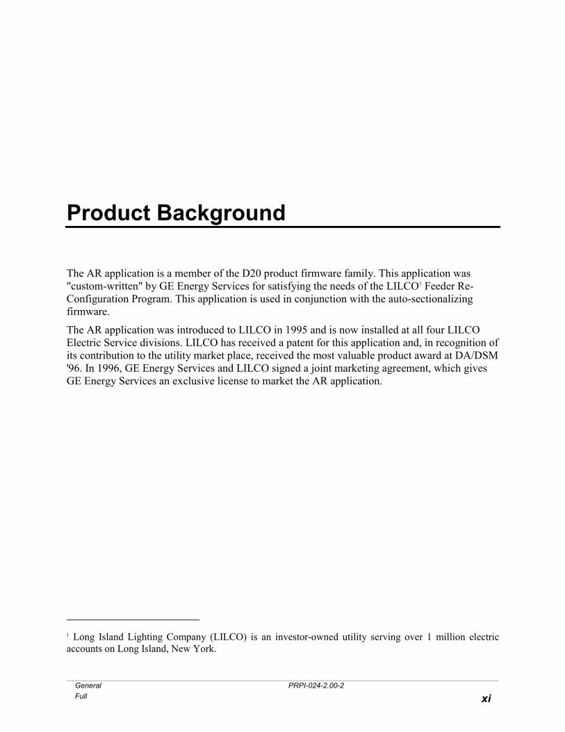
Product Background
The AR application is a member of the D20 product firmware family. This application was "custom-written" by GE Energy Services for satisfying the needs of the LILCO1 Feeder Re-Configuration Program. This application is used in conjunction with the auto-sectionalizing firmware.
The AR application was introduced to LILCO in 1995 and is now installed at all four LILCO Electric Service divisions. LILCO has received a patent for this application and, in recognition of its contribution to the utility market place, received the most valuable product award at DA/DSM '96. In 1996, GE Energy Services and LILCO signed a joint marketing agreement, which gives GE Energy Services an exclusive license to market the AR application.
1 Long Island Lighting Company (LILCO) is an investor-owned utility serving over 1 million electric accounts on Long Island, New York.
Auto-Restoration Data Translation Application Product Description, Information and Specification
PRPI-024-2.00-2 General
xii Full

General PRPI-024-2.00-2 Full 1
Chapter 1: Product Information
1.1 Features of the AR Application
The AR application minimizes outage minutes by automatically restoring power to unfaulted segments of a feeder, which has been sectionalized to isolate a fault. The AR application restores power to as many of the unfaulted segments as possible while maintaining fault isolation without exceeding the capacities of alternate power sources and routes.
The AR application features the following:
• Fault location - the application takes a "snapshot" of the states of the sectionalizing switch controllers, substation breakers and sectionalizing switches and determines the feeder segment that has experienced the overcurrent fault.
• Fault isolation - the application opens or maintains open the sectionalizing switch(es) that will isolate the faulted feeder segment from unfaulted feeder segments.
• Restoration qualification - the application qualifies the ability to restore load by:
• comparing configured segment capacities with the latest maximum hourly load or 72 hour maximum load or latest real time load to ensure that the capacities of the alternate source and carrying segments are not exceeded.
• confirming that alternate source voltage is present.
• Operator notification and acknowledgement - provides a means of interfacing to a host for requesting and obtaining operator acknowledgment. The application provides a means of interfacing to a host certain configuration and run-time values for creating and displaying the current state of a circuit group or the proposed state for a circuit group restoration.
Auto-Restoration Data Translation Application Product Description, Information and Specification
PRPI-024-2.00-2 General
2 Full
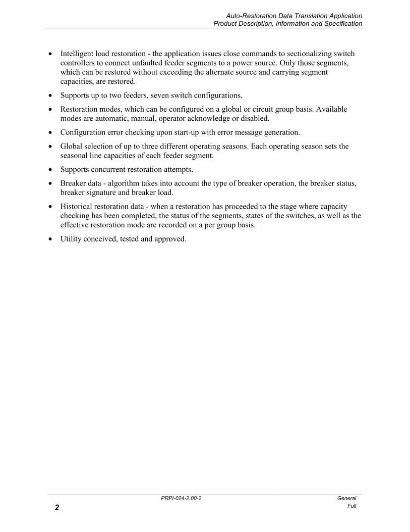
• Intelligent load restoration - the application issues close commands to sectionalizing switch controllers to connect unfaulted feeder segments to a power source. Only those segments, which can be restored without exceeding the alternate source and carrying segment capacities, are restored.
• Supports up to two feeders, seven switch configurations.
• Restoration modes, which can be configured on a global or circuit group basis. Available modes are automatic, manual, operator acknowledge or disabled.
• Configuration error checking upon start-up with error message generation.
• Global selection of up to three different operating seasons. Each operating season sets the seasonal line capacities of each feeder segment.
• Supports concurrent restoration attempts.
• Breaker data - algorithm takes into account the type of breaker operation, the breaker status, breaker signature and breaker load.
• Historical restoration data - when a restoration has proceeded to the stage where capacity checking has been completed, the status of the segments, states of the switches, as well as the effective restoration mode are recorded on a per group basis.
• Utility conceived, tested and approved.

Auto-Restoration Data Translation Application Product Description, Information and Specification
General PRPI-024-2.00-2 Full 3
1.2 Compatibility of the AR Application
1.2.1 Hardware Compatibility
The AR application is currently supported on the D20 and D200 platforms. The memory size for these platforms is application dependent. Contact the factory regarding compatibility for your particular application.
1.2.2 Software Compatibility
1.2.2.1 Switch Sectionalizing Controllers
The AR application must be used in conjunction with the auto-sectionalizing firmware. For information regarding this firmware, refer to the product description, information and specification for this firmware.
1.2.2.2 D20/D200
New and existing D20/D200 installations will require as a minimum firmware which will include the AR application, an application which supplies breaker state, breaker operation type, breaker load, a host application for handling restorations requiring operator acknowledgement, DNP3 DCA, DNP3 data link and ConfigPro 2.34 or greater. Contact GE Energy Services regarding base software compatibility.
1.2.3 Documentation
GE Energy Services will make available a functional specification and a configuration guide specific to this application.
Auto-Restoration Data Translation Application Product Description, Information and Specification
PRPI-024-2.00-2 General
4 Full
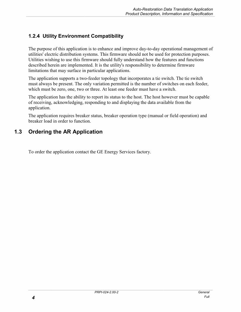
1.2.4 Utility Environment Compatibility
The purpose of this application is to enhance and improve day-to-day operational management of utilities' electric distribution systems. This firmware should not be used for protection purposes. Utilities wishing to use this firmware should fully understand how the features and functions described herein are implemented. It is the utility's responsibility to determine firmware limitations that may surface in particular applications.
The application supports a two-feeder topology that incorporates a tie switch. The tie switch must always be present. The only variation permitted is the number of switches on each feeder, which must be zero, one, two or three. At least one feeder must have a switch. The application has the ability to report its status to the host. The host however must be capable of receiving, acknowledging, responding to and displaying the data available from the application.
The application requires breaker status, breaker operation type (manual or field operation) and breaker load in order to function.
1.3 Ordering the AR Application
To order the application contact the GE Energy Services factory.
General PRPI-024-2.00-2 Full 5
Chapter 2: Product Description
The AR application includes the following features.
2.1 Overview
The AR application provides an automated means of restoring power to unfaulted segments of a feeder, which has been sectionalized to isolate a fault. This sectionalizing often removes power from feeder segments, which are not faulted but have experienced the fault current. The AR application restores power to as many of those unfaulted segments as possible while maintaining fault isolation without exceeding the capacities of alternate power sources and routes.
Restoration is accomplished by opening and closing feeder switches to maintain fault isolation and connect or reconnect unfaulted segments to a power source. The restoration algorithm is dependent on a pre-configured feeder topology, with no more than a maximum number of feeder switches. An example configuration is shown in Figure 1. This diagram shows a group configuration of two feeders, seven switches, three on each feeder, and a seventh switch, called a tie switch. The tie switch must always be present to couple the two feeders in order to supply power to unfaulted segments. The only variation permitted is the number of switches on each feeder, which must be zero, one, two or three. At least one feeder must have a switch. This arrangement of feeders is referred to as a group and is treated independently of any other groups that may be undergoing restoration. The AR application also provides a means of interfacing to a host for accessing configuration and run-time values for the creation and display of line diagrams to show the current state of a group or the proposed state for a group restoration.

Auto-Restoration Data Translation Application Product Description, Information and Specification
PRPI-024-2.00-2 General
6 Full
Switch 1-1Breaker 1
Switch 2-1Breaker 2
Switch 1-2 Switch 1-3
Tie Switch
Switch 2-2 Switch 2-3
Segment1-1
Segment1-2
Segment1-3
Segment1-4
Segment2-4
Segment2-3
Segment2-2
Segment2-1
Downstream
Downstream
Figure 1 Example Feeder Configuration
2.2 System Perspective
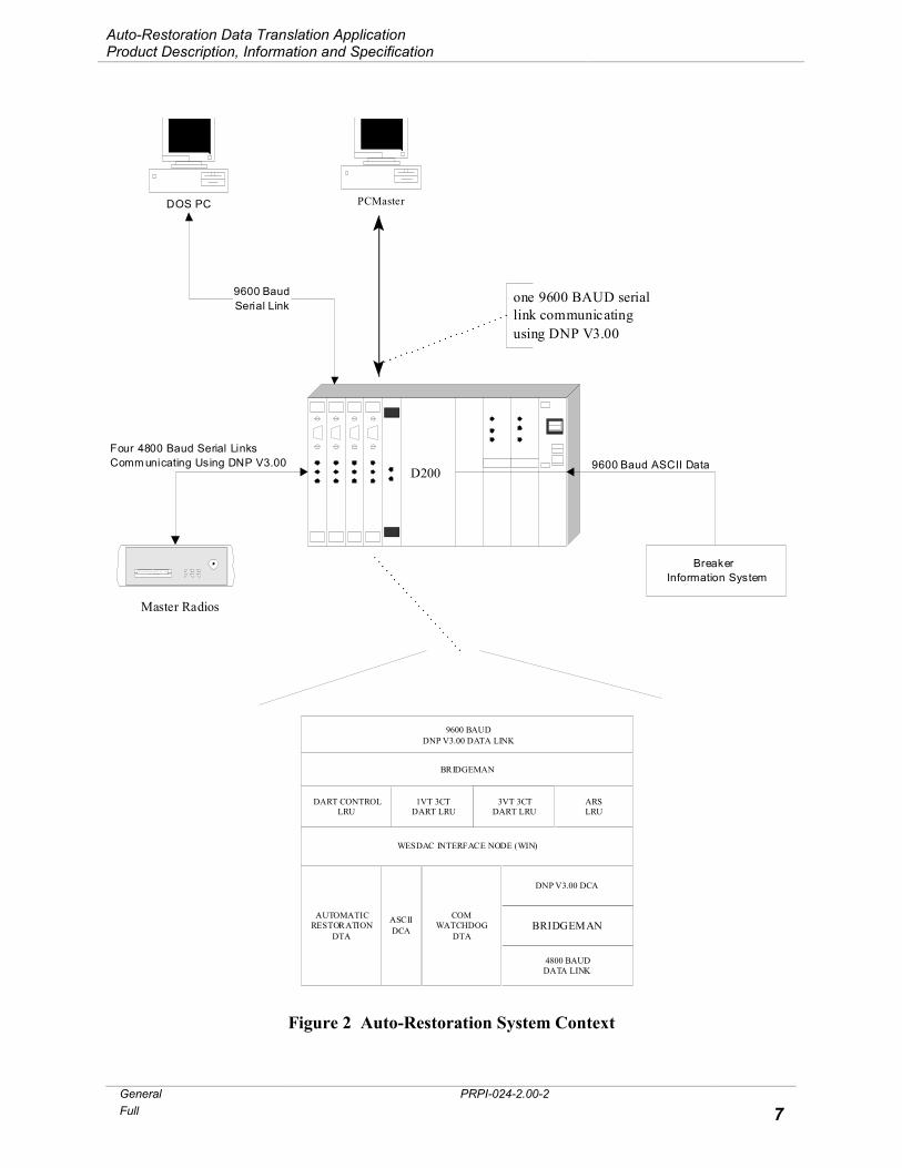
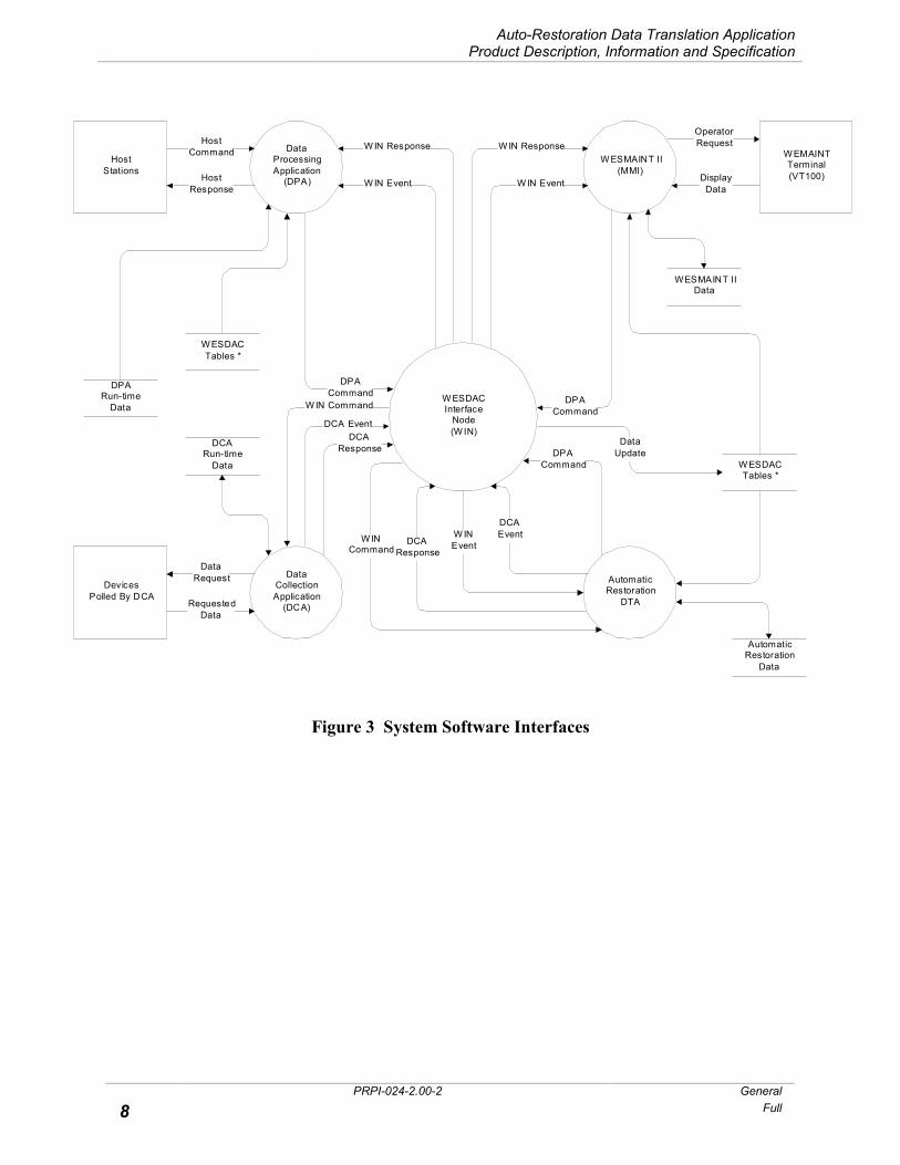
The AR application is a module intended to be integrated in a modular software environment. The following figure shows the data flow between the software modules in a typical integration. As shown in this figure, the WESDAC Interface Node provides the only interface between the AR application and other modules in the system.
A system, which incorporates the AR application, is expected to include:
• Switch sectionalizing controllers containing auto-sectionalizing firmware for controlling feeder switches.
• DNP3 DCA and DNP3 data link for communicating with the switch sectionalizing controllers. The AR application only operates successfully if all information regarding switch status and load is transmitted and received as a single transaction. DNP3 is capable of breaking the response into frames but does not pass these frames for processing until it has received a complete fragment.
• a DCA which supplies breaker state, operation type and load information. This DCA must update the operation type input before the breaker state input.
• a host for handling restorations requiring operator acknowledgment. Although it is not a strict requirement that each of the above items be present for the AR application to function properly, it is required that applications performing functions similar to the above be present. System support is currently provided for the DNP3 data link. Contact the factory for other possible options.
Auto-Restoration Data Translation Application Product Description, Information and Specification
General PRPI-024-2.00-2 Full 7
Figure 2 Auto-Restoration System Context
DART CONTROLLRU
1VT 3CTDART LRU
ARSLRU
WESDAC INTERFACE NODE (WIN)
DNP V3.00 DCA
BRIDGEMAN
4800 BAUDDATA LINK
BRIDGEMAN
9600 BAUDDNP V3.00 DATA LINK
AUTOMATICRESTORATION
DTA
ASCIIDCA
one 9600 BAUD seriallink communicatingusing DNP V3.00
Information System
PCMasterDOS PC
Master Radios
D20M++
COMWATCHDOG
DTA
3VT 3CTDART LRU
9600 BaudSerial Link
Four 4800 Baud Serial LinksComm unicating Using DNP V3.00
D2009600 Baud ASCII Data
Breaker
Auto-Restoration Data Translation Application Product Description, Information and Specification
PRPI-024-2.00-2 General
8 Full
Figure 3 System Software Interfaces
W ESDACInterface
Node(W IN)
HostStations
DevicesPolled By DCA
DPACommand
DataProcessingApplication
(DPA)HostResponse
HostCommand
DataCollectionApplication
(DCA)
DataRequest
RequestedData
DCAResponse
W ESDACTables *
DPARun-time
Data
DCARun-time
Data
W IN Response
W IN Event
W EMAINTTerminal(VT100)
W ESMAINT II(MMI)
DisplayData
OperatorRequest
W IN Command
DCA Event
W IN Response
W IN Event
DPACommand
WESMAINT IIData
W ESDACTables *
DataUpdate
AutomaticRestoration
DTA
AutomaticRestoration
Data
W INEvent
DCAEvent
DPACommand
DCAResponse
W INCommand
Auto-Restoration Data Translation Application Product Description, Information and Specification
General PRPI-024-2.00-2 Full 9
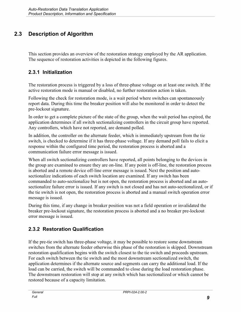
2.3 Description of Algorithm
This section provides an overview of the restoration strategy employed by the AR application. The sequence of restoration activities is depicted in the following figures.
2.3.1 Initialization
The restoration process is triggered by a loss of three-phase voltage on at least one switch. If the active restoration mode is manual or disabled, no further restoration action is taken.
Following the check for restoration mode, is a wait period where switches can spontaneously report data. During this time the breaker position will also be monitored in order to detect the pre-lockout signature.
In order to get a complete picture of the state of the group, when the wait period has expired, the application determines if all switch sectionalizing controllers in the circuit group have reported. Any controllers, which have not reported, are demand polled.
In addition, the controller on the alternate feeder, which is immediately upstream from the tie switch, is checked to determine if it has three-phase voltage. If any demand poll fails to elicit a response within the configured time period, the restoration process is aborted and a communication failure error message is issued.
When all switch sectionalizing controllers have reported, all points belonging to the devices in the group are examined to ensure they are on-line. If any point is off-line, the restoration process is aborted and a remote device off-line error message is issued. Next the position and auto-sectionalize indications of each switch location are examined. If any switch has been commanded to auto-sectionalize but is not open, the restoration process is aborted and an auto-sectionalize failure error is issued. If any switch is not closed and has not auto-sectionalized, or if the tie switch is not open, the restoration process is aborted and a manual switch operation error message is issued.
During this time, if any change in breaker position was not a field operation or invalidated the breaker pre-lockout signature, the restoration process is aborted and a no breaker pre-lockout error message is issued.
2.3.2 Restoration Qualification
If the pre-tie switch has three-phase voltage, it may be possible to restore some downstream switches from the alternate feeder otherwise this phase of the restoration is skipped. Downstream restoration qualification begins with the switch closest to the tie switch and proceeds upstream. For each switch between the tie switch and the most downstream sectionalized switch, the application determines if the alternate source and segments can carry the additional load. If the load can be carried, the switch will be commanded to close during the load restoration phase. The downstream restoration will stop at any switch which has sectionalized or which cannot be restored because of a capacity limitation.
Auto-Restoration Data Translation Application Product Description, Information and Specification
PRPI-024-2.00-2 General
10 Full
After the downstream restoration qualification is determined, the upstream restoration qualification is started by determining the location of the fault. The fault will be located either on the downstream segment of the most downstream sectionalized switch or between the breaker and the most upstream switch. Any upstream switch which is not the most downstream sectionalized switch will be commanded to close during the load restoration phase unless the fault is between the breaker and the most upstream switch. If there is no upstream segment to restore and the tie switch does not have three-phase voltage, the restoration process is aborted and a no alternate voltage source and no upstream segment to restore error message is issued.
Once the position of all switches on the feeder has been determined, if an operator acknowledgement is required, the application's notification buffer is prepared with the appropriate information and the buffer read signal generated.2 Then the application waits for the operator's response. If the buffer is not read or the response does not arrive within the configured time period, the restoration process is aborted and an operator confirm time-out error message is issued. If the operator response is received in time and is not affirmative, the restoration process is aborted and an operator aborted error message is issued.
2.3.3 Load Restoration
Load restoration begins by closing the upstream switches. Switches are closed starting with the one following the breaker (unless the fault is between the breaker and the most upstream switch) and proceeding downstream toward the fault. Each switch is operated in turn when the previous switch provides a positive indication that it has changed to the requested state within the configured time period. If any switch does not change to the requested state within the specified time, the restoration process is aborted and a switch operation failure error message is issued.
Once the upstream restoration is complete, the downstream restoration begins by opening the most downstream switch, which will isolate the fault, and any load, which cannot be supplied from the alternate source. Then the Tie Switch is closed. If any switch does not change to the requested state within the configured time period, the restoration process is aborted and a switch operation failure error message is issued.
Following the completion of the restoration process, whether successful or not, the group restoration mode is set to disabled.
2At this time, additional field events will not be considered by the application.

Auto-Restoration Data Translation Application Product Description, Information and Specification
General PRPI-024-2.00-2 Full 11
2.4 Substation Breaker Data
Each feeder in a group is equipped with a breaker, which will open when it experiences an overcurrent and then attempt a number of recloses. If, after all recloses, the breaker still detects an overcurrent, it will lock out (remain open until manual intervention). This breaker "pre-lockout" sequence is used as a pre-condition for proceeding with a restoration.
There are two binary inputs associated with each breaker to indicate the state of the breaker and whether the last operation was a field operation (ie. protective operation). There are three configuration parameters to specify the timing characteristics of the breaker pre-lockout sequence.
Any breaker operation determined to be a field operation will be used to qualify the breaker pre-lockout signature. This signature consists of a particular sequence of operations performed within the configured time constraints. This signature and the associated time constraints are shown in the following Figure 4. Any breaker operation, which is not a field operation or invalidates the pre-lockout signature will cause the restoration of the associated group to be aborted.
Figure 4 Breaker Signature
t1 t2 t3
Closed
Open
Closed
Open
t1 = maximum initial openduration
t2 = maximum re-closeduration

Auto-Restoration Data Translation Application Product Description, Information and Specification
PRPI-024-2.00-2 General
12 Full
2.5 AR Application from the Operator’s Viewpoint
The following is a dramatization of what an operator can expect to see at the host.
• The system operator is routinely monitoring the communications statistics screen.
• Two circuit groups experience overcurrent faults that cause a number of feeder segments to be automatically sectionalized by the switch sectionalizing controllers. The switch sectionalizing controllers spontaneously report the auto-sectionalization and new line quantities.
• The loss of voltage triggers the AR application to begin a series of preliminary qualification checks.
• The AR application notifies the MMI of an automatic restoration attempt. The notification is via a buffer containing all necessary display information for the operator acknowledgement screens.
• The MMI's screen manager displays the circuit names, the initial time of the attempt and a count down of the time remaining before the auto-restoration attempt is aborted.
• The operator acknowledges the automatic restoration attempt for the first circuit group by toggling the operator acknowledgement key.
• This selection causes the MMI's CRT manager to display the AR future conditions. This screen allows the operator to confirm the actions that the application wants to take and the future state of the feeders. The screen shows the operator the future breaker loads, breaker states, tie switch load, sectionalizing switch loads, capacities of each line segment, line status and sectionalizing switch states. The operator can then proceed with the auto-restoration or cancel by choosing the appropriate poke point. A countdown timer on the screen informs the operator of time remaining to abort. The screen also allows the operator to return to a substation menu for further analysis.
• The operator agrees with the actions suggested by the AR application and pokes on proceed.
• The application issues sequential control commands to restore and isolate the determined segments.
• The AR application notifies the MMI of the completion status of the restoration attempt. It informs of successful and failed attempts. Ten different error codes are used to notify the operator of unsuccessful attempts.
• The application automatically sets the group that has been restored to disabled mode.

Auto-Restoration Data Translation Application Product Description, Information and Specification
General PRPI-024-2.00-2 Full 13
2.6 Configurable Parameters
The user configures
2.6.1 Global Parameters
Global configuration parameters include active season, restoration mode (automatic, manual or disabled), concurrent restorations (allocates a certain amount of system resources for each restoration instance), spontaneous message time-out (specifies the maximum amount of time to wait for spontaneous messages following the first loss of voltage), operator response time-out, switch control output duration, switch operation time-out, demand poll time-out, restoration delay time-out (specifies the length of time to wait after polling the last switch sectionalizing controller before checking the status of remaining switch sectionalizing controllers).
2.6.2 Group Parameters
Group configuration parameters include restoration mode (automatic, manual or disabled), tie switch sectionalizing controller address, status, control output and pseudo control for demand poll for tie switch position, number of switches on the feeder.
2.6.3 Breaker Parameters
Breaker configuration parameters include breaker signature, status for breaker state, status for type of breaker operation, analog point for maximum hourly load, analog point for maximum 72 hour load, segment seasonal capacities (for the feeder segment immediately downstream from the breaker.
2.6.4 Switch Parameters
Switch configuration parameters include switch I.D., status for loss of voltage, status for switch position, status for auto-sectionalize, control output for switch operation, pseudo control point for demand poll, analog for maximum hourly load, analog for maximum 72 hour load, segment seasonal capacities of the feeder segment immediately downstream of the switch.

Auto-Restoration Data Translation Application Product Description, Information and Specification
PRPI-024-2.00-2 General
14 Full
2.7 AR Application System Points
The following table describes the number of points owned by the AR application. This is useful for estimating the amount of information that must be managed by the various platforms in a system. Total point count for the AR application alone for an example system of 20 feeders (10 circuit groups) is also shown in the table.
Point Type Number Example (10 Groups)
Binary inputs 35 + (4 X the number of groups) 75
Binary outputs 4 + (2 X the number of groups) 24
Analog inputs 29 + (27 X the number of groups) 299
Analog outputs 3 3
Table 1 Points Owned by the AR Application
2.8 Configuring an AR System
A system containing the AR application is configured in the following manner:
• Determine the number of system points required by all DCAs/DTAs in your system.
• Configure all applications in your system on an application by application basis.
• Generate the downloadable file and download to the D20/D200.
• Re-start the D20/D200.
• Check for error messages.
2.9 Performance of the AR Application
The number of groups, which can be monitored, will be limited by the amount of system memory. The number of restorations in progress simultaneously will be limited by the speed and power of the processor and the amount of system memory.
The limiting factor in the time required to restore a feeder is expected to be the response time of the external systems responsible for communication with and operation of the field devices.