auto mechanic revised 2009
TRANSCRIPT

1
CURRICULUM
F O R
Auto Mechanic Auto Mechanic Auto Mechanic Auto Mechanic (A Competency Based short-term Curriculum)
Council for Technical Education and Vocational Training
Curriculum Development Division
Sanothimi, Bhaktapur 2009

2
Table of Contents
Introduction ......................................................................................................... 3 Aim ................................................................................................................. 3 Objectives ............................................................................................................ 3 Course Description ................................................................................................ 3 Duration ............................................................................................................... 3 Target Group ........................................................................................................ 3 Group Size ............................................................................................................ 3 Medium of Instruction ........................................................................................... 3 Pattern of Attendance ............................................................................................. 4 Focus of Curriculum .............................................................................................. 4 Entry Criteria ........................................................................................................ 4 Instructional Media and Materials ........................................................................... 4 Teaching Learning Methodologies .......................................................................... 4 Follow up Provision ............................................................................................... 4 Grading System ..................................................................................................... 4 Students Evaluation Details .................................................................................... 5 Trainers' Qualification (Minimum) .......................................................................... 5 Trainer-Trainees Ratio ........................................................................................... 5 Suggestions for Instruction ..................................................................................... 5 Certificate Requirement ......................................................................................... 6 Physical Facilities .................................................................................................. 6 Course Structure of Auto-Mechanic ......................................................................... 8 Basic Fitter ........................................................................................................... 9 Safety Measures and Bench work ............................................................................ 10 Suspension system ................................................................................................ 21 Brake System ....................................................................................................... 31 Steering System .................................................................................................... 46 Wheel and Tyre .................................................................................................... 58 Engine Fitter ....................................................................................................... 65 Engine Overhauling.............................................................................................. 66 Performance steps ................................................................................................ 82 Performance steps ................................................................................................ 84 Cooling and lubrication System .............................................................................. 95 Fuel System with MPFI ....................................................................................... 102 Performance steps .............................................................................................. 104 Performance steps .............................................................................................. 106 Performance steps .............................................................................................. 108 Performance steps ............................................................................................... 111 Transmission Mechanic ...................................................................................... 119 Transmission System .......................................................................................... 120 Differential and Transaxle ................................................................................... 131 Auto Service Mechanic ........................................................................................ 144 Auto Electrician ................................................................................................. 171

3
Introduction The competency based and market oriented modular curriculum for Auto Mechanic is designed to produce employable workforce equipped with knowledge, skills and attitudes related with occupation. In this curriculum, the trainees will practice skills of auto works in the auto workshops and industries. Once the trainees acquired the competencies they will have ample opportunity for employment and self-employment through which they will contribute in the national streamline of poverty reduction in the country.
Aim The main aim of this program is to produce the employable auto mechanics who could provide auto repairing services in the auto workshops in the country and aboard. Objectives After the completion of the training program, the trainees will be able to: 1. Perform bench work 2. Repair suspension /chassis system 3. Maintain brake system 4. Maintain steering system 5. Maintain/ repair wheel and tyre 6. Overhaul engine 7. Maintain cooling system 8. Maintain fuel system 9. Maintain transmission system 10. Maintain differential & transaxle 11. Service vehicle 12. Repair electrical system
Course Description This curricular programmme is based on the job required to be performed by an Auto Mechanic. Therefore, this curriculum is designed to provide skills and knowledge focusing on Auto Mechanics related to the occupation. This curriculum is designed on modular approach, which consists of six modules. These are: Basic fitter, Engine fitter, Transmission mechanic, Auto service Mechanic, and Auto Electrician. There will be two-way demonstration by instructors/trainers and opportunity by trainees to perform skills/tasks necessary for this level of mechanics. Trainees will practice & learn skills using typical tools, equipment, machines and materials necessary for the program. Duration The total duration of the course extends over 390 hours. Target Group The target group for this training program will be all interested individuals in the field of automobile with educational prerequisite of minimum class five pass. Group Size The group size of this training program will be maximum 30, provided all necessary resources to practice the tasks/ competencies as specified in this curriculum. Medium of Instruction The medium of instruction for this program will be Nepali and English.

4
Pattern of Attendance The trainees should have 80% attendance in theory classes and 90% in practical/ performance to be eligible for internal assessments and final examination. Focus of Curriculum This is a competency-based curriculum. This curriculum emphasizes on competency performance. 80% time is allotted for performance and remaining 20% time is for related technical knowledge. So, the main focus will be on performance of the specified competencies in the curriculum. The provision of OJT is made to practice the critical tasks during the stated period. Entry Criteria Individuals who meet the following criteria will be allowed to enter this curricular program:
• Minimum of five class pass or equivalent • Physically and mentally fit • Minimum of 17 years of age • Should pass entrance examination
Preference will be given to the individuals of rural, poor, female, Dalit, Janjati, Disadvantaged Groups (DAGs) and conflict affected people. Instructional Media and Materials
The following instructional media and materials are suggested for the effective instruction and demonstration. � Printed Media Materials (Assignment sheets, Case studies, Handouts, Information
sheets, Individual training packets, Procedure sheets, Performance Check lists, Textbooks etc.).
� Non-projected Media Materials (Display, Models, Flip chart, Poster, Writing board etc.).
� Projected Media Materials (Opaque projections, Overhead transparencies, Slides etc.).
� Audio-Visual Materials (Audiotapes, Films, Slide-tape programs, Videodiscs, Videotapes etc.).
� Computer-Based Instructional Materials (Computer-based training, Interactive video etc.).
Teaching Learning Methodologies The methods of teachings for this curricular program will be a combination of several approaches. Such as Illustrated Lecture, Group Discussion, Demonstration, Simulation, Guided practice, Practical experiences, Fieldwork and Other Independent learning. � Theory: Lecture, Discussion, Assignment, Group work. � Practical: Demonstration, Observation, Guided practice and Self-practice.
Follow up Provision First follow up: Six months after the completion of the program • Second follow up: Six months after the completion of the first follow up • Follow up cycle: In a cycle of one year after the completion of the second follow up for
five years Grading System The trainees will be graded as follows based on the marks in percentage secured by them in tests/ evaluations.
• Distinction: Pass with 80% and above • First Division: Pass with 75% and above • Second Division: Pass with 65% and above • Third Division: Pass with 60% to below 65%

5
Students Evaluation Details • Continuous evaluation of the trainees' performance is to be done by the related instructor/
trainer to ensure the proficiency over each competency under each area of the whole course.
• Related technical knowledge learnt by trainees will be evaluated through written or oral tests as per the nature in the institutional phase of training.
• Trainees must secure minimum marks of 60% in an average of both theory and practical evaluations.
• The entrance test will be administered by the concerned training institute. Trainers' Qualification (Minimum) • Diploma in Auto mechanical engineering or equivalent in related field • Good communicative and instructional skills • Experience in related field Trainer-Trainees Ratio • In theory classes 1(trainer): 20 (trainees) • In practical classes (in workshop and laboratory) 1(trainer): 10 (trainees) Suggestions for Instruction
A 1.Select objective • Write objectives of cognitive domain • Write objectives of psychomotor domain • Write objectives of affective domain
2. Select Subject matter • Study subject matter in detail • Select content related to cognitive domain • Select content related to psychomotor domain • Select content related to affective domain
3. Select Instructional Methods • Teacher centered methods: like lecture, demonstration, question answers inquiry,
induction and deduction methods. • Student initiated methods like experimental, field trip/excursion, discovery,
exploration, problem solving, survey methods. • Interaction methods like discussion, group/team teaching, microteaching and
exhibition. • Dramatic methods like role play and dramatization 4. Select Instructional method (s) on the basis of objectives of lesson plans and KAS
domains 5. Select appropriate educational materials and apply at right time and place. 6. Evaluate the trainees applying various tools to correspond the KAS domains 7. Make plans for classroom / field work / workshop organization and management. 8. Coordinate among objectives, subject matter and instructional methods. 9. Prepare lesson plan for theory and practical classes. 10. Deliver /conduct instruction / program 11. Evaluate instruction/ program
B. Special suggestion for the performance evaluation of the trainees 1. Perform task analysis 2. Develop a detail task performance checklist 3. Perform continuous evaluation of the trainees by applying the performance checklist.
C. Suggestion for skill training 1. Demonstrate task performance in normal speed 2. Demonstrate slowly with verbal description of each and every step in the sequence of
activity of the task performance using question and answer techniques. 3. Repeat 2 for the clarification on trainees demand if necessary 4. Perform fast demonstration of the task.

6
D. Provide trainees the opportunities to practice the task performance demonstration 1. Provide opportunity to trainees to have guided practice 2. Create environment for practicing the demonstrated task performance 3. Guide the trainees in each and every step of task performance 4. Provide trainees to repeat and re-repeat as per the need to be proficient on the given
task performance 5. Switch to another task demonstration if and only trainees developed proficiency in the
task performance. E. Other suggestions
1. Apply principles of skill training 2. Allocate 20% time for theory classes and 80% time for task performance while
delivering instructions 3. Apply principles of learning relevant to learners age group 4. Apply principles of intrinsic motivation 5. Facilitate maximum trainees involvement in learning and task performance activities 6. Instruct the trainees on the basis of their existing level of knowledge, skills and attitude.
Certificate Requirement The related training institute will provide the certificate in “Auto Mechanic" to those trainees who successfully complete all the modules including OJT or as prescribed by the curriculum. However; individuals who complete module (s) of the institutional training will receive the completion certificate of the particular module(s).
Provision for Skill Testing
The graduates who have the completion certificate of “Auto Mechanic" may sit in the skill testing exam of level one (Level-1) as provisioned and administered by the National Skill Testing Board.
Physical Facilities The theory class rooms at least should have area of 10 square feet per trainee and in the workshop it should be at least of 30 square feet per trainees. All the rooms and laboratory should be well illuminated and ventilated.
Well equipped workshop with adequate space 1 (No.) Well furnished class room with adequate space 1 (No.) Office room equipped with modern facilities 1 (No.) Principle room equipped with modern facilities 1 (No.) Reception room equipped with modern facilities 1 (No.)

7
Tools and Equipment 1. Air compressor
2. Battery charger
3. Washing machine
4. Hydraulic lifter
5. Spray gun
6. Vacuum cleaner
7. Soldering iron
8. Spanner set
9. Ring set
10. Socket wrench
11. Screw driver sets
12. Hammer
13. Pliers set
14. Multi-meter
15. Plug wrench
16. Impact driver
17. Filler gauge
18. Bench vice
19. Bench grinder
20. Drill machine and bits
21. Tyre lever
22. Valve puller
23. Lock pliers
24. Scissors
25. Wheel wrench
26. Jack
27. Ratchet
28. Drain plug wrench
29. Specialized puller set
30. Calliper
31. Torque wrench
32. Funnel
33. Wire brush
34. File set
35. Oil gun
36. Centre punch
37. Filter wrench
38. Chain puller
39. Oil cane
40. Pressure gauge

8
Course Structure of Auto-Mechanic
S.N. Modules and sub-modules Nature Total Time Full Marks 1. M1: Basic Fitter (General Auto
Mechanic) • Safety Measures and Bench work • Suspension System • Brake System • Steering System • Wheels and Tyres System
T+P 130 20 25 40 30 15
100
2. M2: Engine Fitter • Engine Overhauling • Cooling and Lubrication System • Fuel System with MPFI
T+P 120 75 15 30
100
3. M3: Transmission Mechanic • Transmission System • Differential and Transaxle System
T+P 50 30 20
35
4. M4: Auto Service Mechanic
T+P 50 35
5. M5: Auto Electrician T+P 40
30
Total 390 300
9
Module: 1
Basic Fitter Description This module is designed to equip trainees with the skills and knowledge on Basic Fitting as a specialized module related to the occupation. This module intends to provide skills and knowledge on bench work, suspension system, brake, steering and wheel and tyre. Objectives: After completion of this module the trainees will be able to:
1. Perform bench work 2. Maintain suspension system 3. Maintain brake system 4. Maintain steering system 5. Maintain/ repair wheel and tyre
Sub modules:
1. Bench Work 2. Suspension 3. Brake 4. Steering 5. Wheels and Tyre

10
Module 1 Sub module 1.1
Safety Measures and Bench work
Description: This sub module intends to provide the knowledge and skills on Safety measures which must to be applied while working in the workshop safely minimizing lost of lives and properties. This course also provides knowledge and skills about Handling of tools and equipment and Performing bench work skills related to the job Objectives: After completion of this module the trainees will be able: 1. Orient with safety rules 2. Handle tools and equipments 3. Perform bench work activities Duration: 20 hours (4 hours theory and 16 hours practical) Tasks: 1. Follow safety measures 2. Prevent electrical hazard 3. Store highly inflammable materials 4. Apply first aid 5. Identify/enumerate tools/equipment/materials. 6. Measure/mark the given W/P 7. File flat surface 8. File external radius 9. Saw the metal by hand 10. Drill a hole

11
Task Analysis
Task No. 1 Follow safety measures.
Time: 4 hrs Theory: 2 hrs Practical: 2 hrs
Performance steps Terminal Performance Objective
Related Technical Knowledge
1 Select personal protective equipment (PPE) as required
2 Wear required safety devices 3 Inspect and maintain safe work area 4 Follow established procedures for
the use and care of tools 5 Follow established procedures for
the use and care of equipments 6 Follow established procedures for
the use and care of power operated equipment
7 Follow established procedures for the use and care of safety equipments
8 Enlist safety signs/notice. 9 Enlist preparation for emergency
response. 10 Identify basic first-aid procedures 11 Lift objects and materials in
accordance with established procedures
Condition (Given): Class room OHP, transparency, white board and marker, handouts and safety poster Task (What): Orient with safety rues Follow safety measures. Standard (How well): Safety rules and regulation oriented. Safety measures followed in sequential order.
� Definition of safety � Safety rules and
regulations � Important of safety � Workshop hazards � Personal and
workshop safety rules and regulations
� Safety sign and notice � Emergency response � First Aid � Hazards related to
jobs (Accident hazards,
Physical hazards, Chemical hazards, Biological hazards and Ergonomic, psychosocial and organizational factors) � Preventive measures
Tools/equipment: Safety sign and notice Safety:

12
Task Analysis
Task No: 2 Prevent electrical hazard.
Time 1 hr Theory 0. hr Practical 1 hr
Performance steps Terminal Performance Objective
Related Technical Knowledge
1. Check the electrical wiring 2. Ensure all the wire connection is
properly taped 3. Ensure the proper earthling 4. Ensure non of the socket and pin is
loosely connected 5. Use rubber shoe while working with
electrical lines
Condition(Given): Electrical wiring, instruments and devices Task (What):
Prevent electrical hazard
Standard (How Well): Electrical connections, devices and instruments checked before working.
� Principle of electricity generation
� Concept of and current, voltage & resistant
� Parallel and series connection
� Concept of earthling � Electrical devices,
instrument & appliances
� Loose connection and necked eye
� Possible hazards
Required tools/equipment: Safety:
� Do not touch any electrical connection and appliance with wet hand

13
Task Analysis
Required tools/equipment: Safety:
� Check expiry date of fire extinguisher � Do not store materials related to fire near this store
Task No: 3 Store highly inflammable materials.
Time 1 hr Theory 0.5 hr Practical 0.5 hr
Performance steps Terminal Performance Objective
Related Technical Knowledge
1. Segregate all inflammable material
2. Seal the container carefully
3. Select a dry cool safe place where fire can not reach to store inflammable material
4. Put the rack and make specific location to place specific products
5. Store inflammable material in a designated location
6. Mark “Inflammable material” in this location
7. Put fire extinguisher as required in this store
Condition (Given): Store, inflammable materials Task (What): Store highly inflammable materials Standard (How Well): Highly inflammable materials stored as per instructions.
� Different inflammable materials
� Procedure � Safety precautions

14
Task Analysis
Task No: 4 Apply first aid.
Time 1 hr Theory 0.5 hr Practical 0.5 hr
Performance steps Terminal Performance Objective
Related Technical Knowledge
1. Identify different kind of hazards
and injuries occurred in auto shop
2. Apply first aid for burn 3. Apply artificial respiration 4. Apply first aid for cuts
Condition (Given): First aid box Task (What): Perform first aid. Standard (How Well): First aid procedures for different cases applied.
� Importance of first aid � First aid kit with
necessary medicine and materials
� First aid technique
Required tools/equipment: Safety:
� First aid box need to be maintained � First aid technique need to be followed exactly as specified

15
Task Analysis
Task No: 5 Identify/enumerate tools/equipment/materials.
Time 2 hrs Theory 1 hr Practical 1 hr
Performance steps Terminal Performance Objective
Related Technical Knowledge
1. Receive instructions 2. Visit tools/equipment/materials
display room. 3. Identify/enumerate different tools. 4. Enlist the function of identified and
different enumerated tools. 5. Identify/enumerate different
equipment. 6. Enlist the function of different
identified and enumerated tools. 7. Identify/enumerate different painting
materials /chemicals. 8. Enlist the application of identified and
enumerated materials. 9. Keep records.
Condition (Given): Tools, equipment and materials displaying Task (What): Identify/enumerate tools/equipment/materials. Standard (How Well): Different tools, equipment and materials identified and enumerated as well as their functions enlisted.
� Identification of
different tools, equipment and materials
� Function of different tools and equipment
� Application of materials
� Identification and enumerating procedure
Required tools/equipment: Different tools, equipment and materials Safety:
• Care should be taken while using tools and equipments.
• Follow workshop safety rules.

16
Task Analysis
Task No: 6 Measure/mark the given W/P
Task Performance steps Terminal Performance
Objectives Related Technical
Knowledge 1. Obtain required drawings. 2. Study drawing carefully. 3. Obtain required tools. 4. Obtain required (material) work piece. 5. Measure work piece. 6. Mark on work piece according to
dimension of given drawing. 7. Clean all the tools & Re-store at proper
place. 8. Clean the working place.
Condition (Given):- Workshop, work piece, measuring & marking instruments work piece material. Task (What):- Measure/ mark the given W/P. Standard (How well):- The given w/p measure and marked.
� Systems of measurements
� (MKS and FPS) � Units of
measurements � Conversion of
measurement units � Identification of
measuring and marking instruments
� Procedure � Safety precautions
Required tools/equipment: Safety:
• Handle the tools carefully.
• Follow workshop safety rules.
• Don't put the measuring tools mix with cutting or other tools.

17
Task Analysis Task No: 7 File flat surface
Task Performance steps Terminal Performance Objectives
Related Technical Knowledge
1. Obtain flat file. 2. Obtain work piece. 3. Obtain steel rule. 4. Clean the vice. 5. Clamp the work piece on the vice (the flat
surface should be up ward) 6. Hold the file's handle with one hand & put
another hand's thump on the file's tip. 7. Position the feet to safe stance during
filling. 8. Put the file on top of the work piece &
pushing from one hand (holding hand) & pressing only another hands thumb.
9. Return the file without pressure. 10. Apply the same motion to produce even
removal of filling surface. 11. Check the flatness diagonally & cross,
using steel rule. 12. Repeat the same motion of filling until
producing even surface. 13. Clean all the tools & put it back to proper
place. 14. Clean the vice & working place.
Condition (Given):- Flat files, working bench & bench vice well-equipped fitter workshop, work piece material. Task (What):- |File flat surface. Standard (How well):- Work piece-clamping, position of body & feet, holding of file, motion of filling & surface finishing wear checked.
� Function of vice & its types
� Function of files & its type
� Methods of filling � Procedure � Safety precautions
Required tools/equipment: Safety:
• Stet up the height of bench vice before start filling.
• Use the whole length of the file.
• Don't use the file with damage or broken handle.
• Use wires brush for clean the file teeth.
• Follow workshop safety rules.

18
Task Analysis Task No: 8 File external radius
Task Performance steps Terminal Performance Objectives
Related Technical Knowledge
1. Obtain drawing. 2. Obtain work piece. 3. Obtain file set. 4. Obtain radius gauge as required size. 5. Obtain required tools & equipment. 6. Measure & mark lay out according to the
given drawing. 7. Punch dot over the marking line. 8. Clamp the work piece projecting the
corner part that has to be made radius. 9. File down to make curve surface until
closing to marked radius line using rough file.
10. Change medium half round file, start filling along the curved line until and marked line touches.
11. Check periodically with a radius gauge. 12. File down further surface until required
radius is obtain in same motion by fine half round file.
13. Remove the work piece from vice & check the final measurement.
14. Clean all the tools & equipment & put it back.
15. Clean working place.
Condition (Given):- Workshop, working bench & bench vice drawing, work piece, file set, radius gauge, center punch & hammer, steel rule, compass, W/P material. Task (What):- File external radius Standard (How well):- Work piece clamping checked Filling method checked Radius by radius gauge checked.
� Importance of marking & laying out
� Radius gauge & compass
� Procedure � Safety precautions
Required tools/equipment: Safety:
• Set up the height of the bench vice before start filling.
• Use the whole length of the file.
• Don't uses the broken or damaged file handle.
• Follow workshop safety rules.

19
Task Analysis Task No: 9 Saw the metal by hand
Task Performance steps Terminal Performance Objectives
Related Technical Knowledge
1. Obtain work piece. 2. Obtain drawing. 3. Obtain required tools. 4. Mark the symmetrically lines. 5. Punch dotted on marked line. 6. Clamp the work piece on the vice
(the marked line must be out side from the vice)
7. Check the blade & set up the blade on the hack saw frame.
8. Mark a small "V" notch at starting point using small triangular file.
9. Hold hack saw frame & start cutting slowly moving the blade forward.
10. Apply pressure only during forward & back without pressure.
11. Check the cutting ways for straightness.
12. Move down slowly while finishing a cut.
13. Check the sawed part. 14. Clean all the tools & equipment
& put it back. 15. Clean the working place & vice.
Condition (Given):- Workshop, drawing, bench vice, hack saw & blade, scriber, steel rule, hammer, center punch, work piece material. Task (What):- Saw the metal by hand. Standard (How well):- Marking & Dot punching checked. Vee notch checked. Cutting straightness checked. Dimension of the sawed part checked.
� Importance of hacksaw
� Use of hacksaw blade for different metal
� Holding of work piece for sawing
� Procedure of sawing metal by hand
� Safety precautions
Required tools/equipment: Safety:
• The work piece clamped perfectly.
• The teeth of the hack saw blade kept forward direction.
• Don't move the blade left right during sawing.
• Incline the blade is 150 during sawing.
• Follow general safety rules.
20
Task Analysis
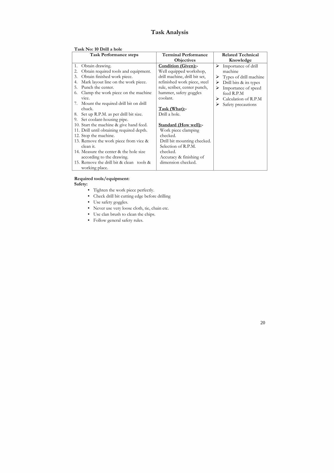
Task No: 10 Drill a hole
Task Performance steps Terminal Performance Objectives
Related Technical Knowledge
1. Obtain drawing. 2. Obtain required tools and equipment. 3. Obtain finished work piece. 4. Mark layout line on the work piece. 5. Punch the center. 6. Clamp the work piece on the machine
vice. 7. Mount the required drill bit on drill
chuck. 8. Set up R.P.M. as per drill bit size. 9. Set coolant-housing pipe. 10. Start the machine & give hand feed. 11. Drill until obtaining required depth. 12. Stop the machine. 13. Remove the work piece from vice &
clean it. 14. Measure the center & the hole size
according to the drawing. 15. Remove the drill bit & clean tools &
working place.
Condition (Given):- Well equipped workshop, drill machine, drill bit set, refinished work piece, steel rule, scriber, center punch, hammer, safety goggles coolant. Task (What):- Drill a hole. Standard (How well):- Work piece clamping checked. Drill bit mounting checked. Selection of R.P.M. checked. Accuracy & finishing of dimension checked.
� Importance of drill machine
� Types of drill machine � Drill bits & its types � Importance of speed
feed R.P.M � Calculation of R.P.M � Safety precautions
Required tools/equipment: Safety:
• Tighten the work piece perfectly.
• Check drill bit cutting edge before drilling
• Use safety goggles.
• Never use very loose cloth, tie, chain etc.
• Use clan brush to clean the chips.
• Follow general safety rules.

21
Module:1 Sub Module 2
Suspension system Description: This sub module intends to provide knowledge and skills about auto suspension system. Objectives: After completion of this module the trainees will be able to: 1. Be familiar with suspension /chassis system 2. Repair suspension /chassis system Duration: 25 hours (5 hours theory and 20 hours practical) Tasks:
1. Replace suspension bush/pin. 2. Change suspension/ control arm. 3. Replace coil spring. 4. Change strut. 5. Replace shock absorbers. 6. Replace spring hanger/shackle pin. 7. Replace leaf spring. 8. Replace torsion bar. 9. Replace stabilizer bar.
22
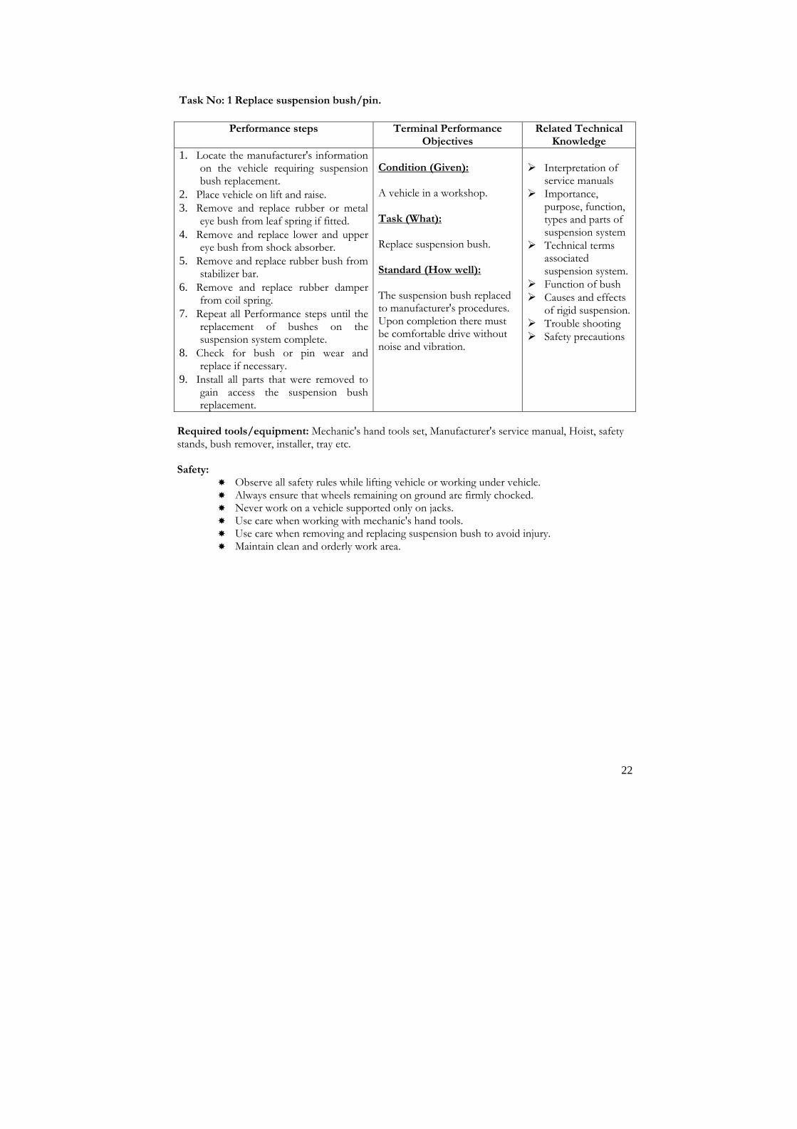
Task No: 1 Replace suspension bush/pin.
Performance steps Terminal Performance Objectives
Related Technical Knowledge
1. Locate the manufacturer's information on the vehicle requiring suspension bush replacement.
2. Place vehicle on lift and raise. 3. Remove and replace rubber or metal
eye bush from leaf spring if fitted.
4. Remove and replace lower and upper eye bush from shock absorber.
5. Remove and replace rubber bush from stabilizer bar.
6. Remove and replace rubber damper from coil spring.
7. Repeat all Performance steps until the replacement of bushes on the suspension system complete.
8. Check for bush or pin wear and replace if necessary.
9. Install all parts that were removed to gain access the suspension bush replacement.
Condition (Given): A vehicle in a workshop. Task (What): Replace suspension bush. Standard (How well): The suspension bush replaced to manufacturer's procedures. Upon completion there must be comfortable drive without noise and vibration.
� Interpretation of
service manuals � Importance,
purpose, function, types and parts of suspension system
� Technical terms associated suspension system.
� Function of bush � Causes and effects
of rigid suspension. � Trouble shooting � Safety precautions
Required tools/equipment: Mechanic's hand tools set, Manufacturer's service manual, Hoist, safety stands, bush remover, installer, tray etc. Safety:
� Observe all safety rules while lifting vehicle or working under vehicle. � Always ensure that wheels remaining on ground are firmly chocked. � Never work on a vehicle supported only on jacks. � Use care when working with mechanic's hand tools. � Use care when removing and replacing suspension bush to avoid injury. � Maintain clean and orderly work area.

23
Task No: 2 Change suspension/ control arm.
Performance steps Terminal Performance Objectives
Related Technical Knowledge
1. Locate the suspension arm needs replacement.
2. Place vehicle on lift and rise.
3. Replace wheels and tyres.
4. Support the vehicle to make the suspension arm free from load.
5. Remove bracket or other hardware to gain access to the suspension arm.
6. Remove the lower/upper or both control arm from axle or frame/chassis.
7. Repeat these Performance steps to both left and right sides of front and rear of the vehicle to remove the suspension arms.
8. Check the stiffness and straightness of the arms.
9. Replace new arms and bushes to the frame.
10. Check for bush or mounting bolts wear or slip, replace if necessary.
11. Install all parts that were removed to gain access the suspension arm replacement.
Condition (Given): A vehicle in a workshop .
Task (What): Replace suspension control arm. Standard (How well): The suspension control arm replaced and the system controlled rolling and pitching resistance.
� Interpretation of
service manuals � Identification,
types and parts of suspension arms.
� Technical terms associated suspension arms.
� Function of control arms
� Causes and effects of rigid suspension
� Trouble shooting � Safety precautions
Required tools/equipment: Mechanic's hand tools set, Manufacturer's service manual, Hoist, safety stands, bush remover, installer, jacks, axle stands etc. Safety:
� Observe all safety rules while lifting vehicle or working under vehicle. � Always ensure that wheels remaining on ground are firmly chocked. � Never work on a vehicle supported only on jacks. � Use care when working with mechanic's hand tools. � Use care when removing and replacing suspension arm to avoid injury. � Maintain clean and orderly work area.

24
Task No: 3 Replace coil spring.
Performance steps Terminal Performance Objectives
Related Technical Knowledge
1. Determine the types of suspension system whether it is McPerson strut type or independent coil spring types.
2. Lift the vehicle side of the coil spring to be removed and place safety stands.
3. Apply hand brakes if equipped and works.
4. Chock the other wheels.
5. Remove shock absorbers from the coil spring side.
6. Clamp the coil spring by using coil spring compressor.
7. Raise the jack little by little until the coil spring is free from vehicle load.
8. Remove the coil spring along with spring compression tool.
9. Unfasten the coil spring compressor and remove coil spring.
10. Check the strength and compression force of the coil spring.
11. Get new or replacement coil spring. 12. Clamp the new coil spring.
13. Replace the clamped spring to its position.
14. Remove coil spring compressor. 15. Install the shock absorber. 16. Lower the jack and remove safety stand and chock.
17. Repeat the Performance steps until all the coil spring changed from the vehicle.
Condition (Given): A vehicle in a workshop.
Task (What): Replace coil spring. Standard (How well): The coil springs changed and the vehicle provided comfortable journey.
� Interpretation of
service manuals � Importance,
purpose, functions of coil springs
� Technical terms associated with coil springs
� Operating principles, functions and types of coil springs
� Causes and effects of rigid suspension
� Trouble shooting � Safety precautions
Required tools/equipment: Mechanic's hand tools set, Manufacturer's service manual, Hoist, safety stands, Coil spring compressor, jacks, axle stands, chocks, mobile hydraulic jack etc. Safety:
� Ensure that the vehicle is on a level surface. � A vehicle supported by a jack or bricks are a potential danger. � Always ensure that wheels remaining on ground are firmly chocked. Chocks must be
placed under one of the wheels not being raised. � Never work on a vehicle supported only on jacks. � Use care when working with mechanic's hand tools. � Use care when removing and replacing coil springs to avoid bodily injury. � Maintain clean and orderly work area.

25
Task No: 4 Change strut.
Performance steps Terminal Performance Objectives
Related Technical Knowledge
1. Determine the types of suspension system whether it is Mcpersion strut type or independent coil spring types.
2. Lift the vehicle side of the strut to be removed and place safety stands.
3. Apply hand brakes or chock the wheels.
4. Remove shock absorbers from the coil spring side.
5. Clamp the coil spring by using coil spring compressor.
6. Raise the jack little by little until the coil spring is free from vehicle load.
7. Remove the coil spring along with spring compression tool.
8. Remove the strut and control arms. 9. Unfasten the coil spring compressor and remove coil spring.
10. Check the strength and compression force of the coil spring.
11. Check the condition of the strut. 12. Get new or replacement strut.
13. Install the strut to it's position. 14. Clamp the new or replacement coil spring. 15. Replace the clamped spring to its position.
16. Remove coil spring compressor.
17. Install the shock absorber. 18. Lower the jack and remove safety stand and chock.
19. Repeat the Performance steps until all the coil spring changed from the vehicle.
Condition (Given): A vehicle in a workshop.
Task (What): Replace strut. Standard (How well): The strut and coil springs changed and the vehicle provided comfortable journey.
� Interpretation of
service manuals � Importance,
purpose, functions of strut
� Technical terms associated with struts
� Operating principles, functions and types of struts.
� Causes and effects of rigid suspension
� Trouble shooting � Safety precautions
Required tools/equipment: Mechanic's hand tools set, Manufacturer's service manual, Hoist, safety stands, Coil spring compressor, jacks, axle stands, chocks, mobile hydraulic jack etc. Safety:
� Ensure that the vehicle is on a level surface. � A vehicle supported by a jack or bricks is a potential danger. � Always ensure that wheels remaining on ground are firmly chocked. Chocks must be
placed under one of the wheels not being raised. � Never work on a vehicle supported only on jacks. � Use care when working with mechanic's hand tools. � Use care when removing and replacing coil springs to avoid bodily injury. � Maintain clean and orderly work area.

26
Task No: 5 Replace shock absorbers.
Performance steps Terminal Performance Objectives
Related Technical Knowledge
1. Determine the types of shock absorbers requiring replacement.
2. Apply hand brakes. 3. Lift the vehicle side of the shock absorber
to be removed and place safety stands. 4. Place the chocks under one of the wheels
not being raised.
5. Remove shock absorbers nuts from axle and body of the vehicle.
6. Raise the jack little by little until the shock absorber is free from vehicle load.
7. Remove the shock absorber.
8. Check the shock absorber. 9. Get new or replacement shock absorber.
10. Replace the shock absorber with new bush in its position.
11. Torque the shock absorber. 12. Lower the jack and remove safety stand
and chock.
13. Repeat the Performance steps until all the shock absorber changed from the vehicle.
Condition (Given): A vehicle in a workshop.
Task (What): Change shock absorbers. Standard (How well): Shock absorbers nut removed. Shock absorbers replaced Shock absorbers torqued.
� Interpretation of
service manuals � Importance,
identification types and uses of shock absorber
� Technical terms associated with shock absorber
� Causes and effects of rigid suspension
� Safety precautions
Required tools/equipment: Mechanic's hand tools set, Manufacturer's service manual, Hoist, safety stands, Coil spring compressor, jacks, axle stands, chocks, mobile hydraulic jack etc. Safety:
� Ensure that the vehicle is on a level surface. � A vehicle supported by a jack or bricks are a potential danger. � Always ensure that wheels remaining on ground are firmly chocked. Chocks must be
placed under one of the wheels not being raised. � Never work on a vehicle supported only on jacks. � Use care when working with mechanic's hand tools. � Use care when removing and replacing shock absorber to avoid bodily injury. � Maintain clean and orderly work area.

27
Task No: 6 Replace spring hanger/shackle pin.
Performance steps Terminal Performance Objectives
Related Technical Knowledge
1. Determine the types of spring hanger requiring replacement.
2. Apply hand brakes. 3. Lift the vehicle under the differential and
place safety stands. 4. Place the chocks under one of the wheels
not being raised.
5. Support the body of the vehicle near to the spring hanger.
6. Remove shackle pin lock nut and shackle pin.
7. Remove spring hanger mounting nuts from body/frame of the vehicle.
8. Raise the jack little by little until the spring hanger is free from vehicle load.
9. Remove the spring hanger.
10. Check the metal or rubber eye bush, shackle pin and hanger.
11. Get new or replacement shackle pin, bush and spring hanger.
12. Replace the spring hanger with new bush in its position.
13. Align the eye hole of main leaf coincide with shackle pin and hanger.
14. Install the shackle pin and lock it. 15. Lower the jack and remove safety stand
and chock. 16. Repeat the Performance steps to next leaf
spring.
Condition (Given): A vehicle in a workshop.
Task (What): Change shackle pin, bush and spring hanger. Standard (How well): The shackle pin, bush and spring hanger changed and the vehicle provided comfortable journey.
� Interpret service
manuals � Importance,
purpose, types and uses of leaf spring
� Technical terms associated with leaf spring
� Working principles and function of leaf spring hanger and shackle
� Causes and effects of leaf spring failure
� Trouble shooting � Safety precautions
Required tools/equipment: Mechanic's hand tools set, Manufacturer's service manual, Hoist, safety stands, jacks, axle stands, chocks, mobile hydraulic jack etc. Safety:
� Ensure that the vehicle is on a level surface. � A vehicle supported by a jack or bricks is a potential danger. � Always ensure that wheels remaining on ground are firmly chocked. Chocks must be
placed under one of the wheels not being raised. � Never work on a vehicle supported only on jacks. � Use care when working with mechanic's hand tools. � Use care when removing and replacing spring hanger/shackle to avoid bodily injury. � Maintain clean and orderly work area.

28
Task No: 7 Replace leaf spring.
Performance steps Terminal Performance Objectives
Related Technical Knowledge
1. Determine and locate the leaf spring requiring replacement.
2. Apply hand brakes. 3. Lift the vehicle under the differential and
place safety stands. 4. Place the chocks under one of the wheels
not being raised.
5. Raise the jack little by little until the spring hanger is free from vehicle load.
6. Support the body of the vehicle near to the leaf spring hanger.
7. Remove the shackle pin.
8. Remove U-bolts and clamp plate from axle housing.
9. Lift the leaf spring assembly from vehicle. 10. Clamp the spring leaves assembly to bench
vice.
11. Remove the leaf spring metal clamps. 12. Remove center bolt from leaf spring
assembly. 13. Separate spring leaves. 14. Examine the soft and broken leaves.
15. Get new spring leaves as per sizes. 16. Clamp the set of spring leaves with center
bolt and metal clamps.
17. Check the metal or rubber eye bush, shackle pin and hanger.
18. Get new or replacement shackle pin, bush and spring hanger.
19. Replace the spring hanger with new bush in its position.
20. Install the leaf springs to its position. 21. Align the eye hole of main leaf coincide
with shackle pin and hanger. 22. Install the shackle pin and lock it. 23. Mount the U-bolts to the axle housings. 24. Lower the jack and remove safety stand
and chock.
25. Repeat the Performance steps to next leaf spring.
Condition (Given): A vehicle in a workshop.
Task (What): Change leaf spring. Standard (How well): Shackle pin removed. Leaf spring lifted. Leaf spring removed. Leaf spring installed in its position.
� Interpret service
manuals � Importance,
purpose, types and uses of leaf spring.
� Technical terms associated conventional leaf spring type suspension
� Working principles, functions and types of leaf spring
� Causes and effects of leaf spring failure
� Trouble shooting � Safety precautions
Safety: � Ensure that the vehicle is on a level surface. � A vehicle supported by a jack or bricks are a potential danger. � Always ensure that wheels remaining on ground are firmly chocked. Chocks must be
placed under one of the wheels not being raised.

29
Task No: 8 Replace torsion bar.
Performance steps Terminal Performance Objectives
Related Technical Knowledge
1. Determine the types of torsion bar whether it is parallel to or laterally to the frame side members.
2. Lift the vehicle removed and place safety stands.
3. Apply hand brakes or chock the wheels. 4. Remove the wheels.
5. Remove steering knuckle or trailing arm.
6. Remove upper and lower ball joints. 7. Remove pivot pins and control arms.
8. Remove circlip lock.
9. Remove bearing support. 10. Remove torsion bar anchor plate.
11. Remove torsion bars.
12. Inspect torsion bars. 13. Replace new torsion bars. 14. Replace all parts that were removed earlier
in reverse order. 15. Lower the jack and remove safety stand
and chock. 16. Repeat the Performance steps until all the
torsion bar changed from the vehicle.
Condition (Given): A vehicle in a workshop.
Task (What): Replace torsion bar. Standard (How well): The torsion bar removed, checked and replaced and the vehicle provided comfortable journey.
� Interpret service
manuals � Importance, purpose,
advantages and function of torsion bar
� Working principles, functions and types of torsion bar
� Technical terms associated with torsion bar
� Causes and effects of rigid suspension
� Trouble shooting � Safety precautions
Required tools/equipment: Mechanic's hand tools set, Manufacturer's service manual, Hoist, safety stands, jacks, axle stands, chocks, mobile hydraulic jack etc. Safety:
� Ensure that the vehicle is on a level surface. � A vehicle supported by a jack or bricks is a potential danger. � Always ensure that wheels remaining on ground are firmly chocked. Chocks must be
placed under one of the wheels not being raised. � Never work on a vehicle supported only on jacks. � Use care when working with mechanic's hand tools. � Use care when removing and replacing torsion bar to avoid bodily injury. � Maintain clean and orderly work area.

30
Task No: 9 Replace stabilizer bar.
Performance steps Terminal Performance Objectives
Related Technical Knowledge
1. Jack up vehicle and support on stands.
2. Apply hand brakes or chock the wheels 3. Remove wheel.
4. Loosen the stabilizer link bolts.
5. Remove stabilizer link. 6. Remove stabilizer bar.
7. Check the stabilizer.
8. Obtain new or replacement stabilizer. 9. Replace stabilizer.
10. Replace new suspension bushes. 11. Install stabilizer link. 12. Torque the stabilizer link bolts. 13. Lower the jack and remove safety stand and
chock.
Condition (Given): A serviceable vehicle in a workshop.
Task (What): Replace stabilizer bar. Standard (How well): The stabilizer bar and suspension bush is replaced according to manufacturer's procedures and specifications.
� Interpretation of
service manual � Importance,
purpose, functions of stabilizer bar
� Working principles, functions and types of stabilizer bar
� Causes and effects of stabilizer bar malfunctioning
� Trouble shooting � Safety precautions
Required tools/equipment: Mechanic's hand tools set, Manufacturer's service manual, Hoist, safety stands, jacks, axle stands, chocks, mobile hydraulic jack etc. Safety:
� Ensure that the vehicle is on a level surface. � A vehicle supported by a jack or bricks are a potential danger. � Always ensure that wheels remaining on ground are firmly chocked � Never work on a vehicle supported only on jacks. � Use care when working with mechanic's hand tools. � Use care when removing and replacing stabilizer to avoid bodily injury. � Maintain clean and orderly work area.
31
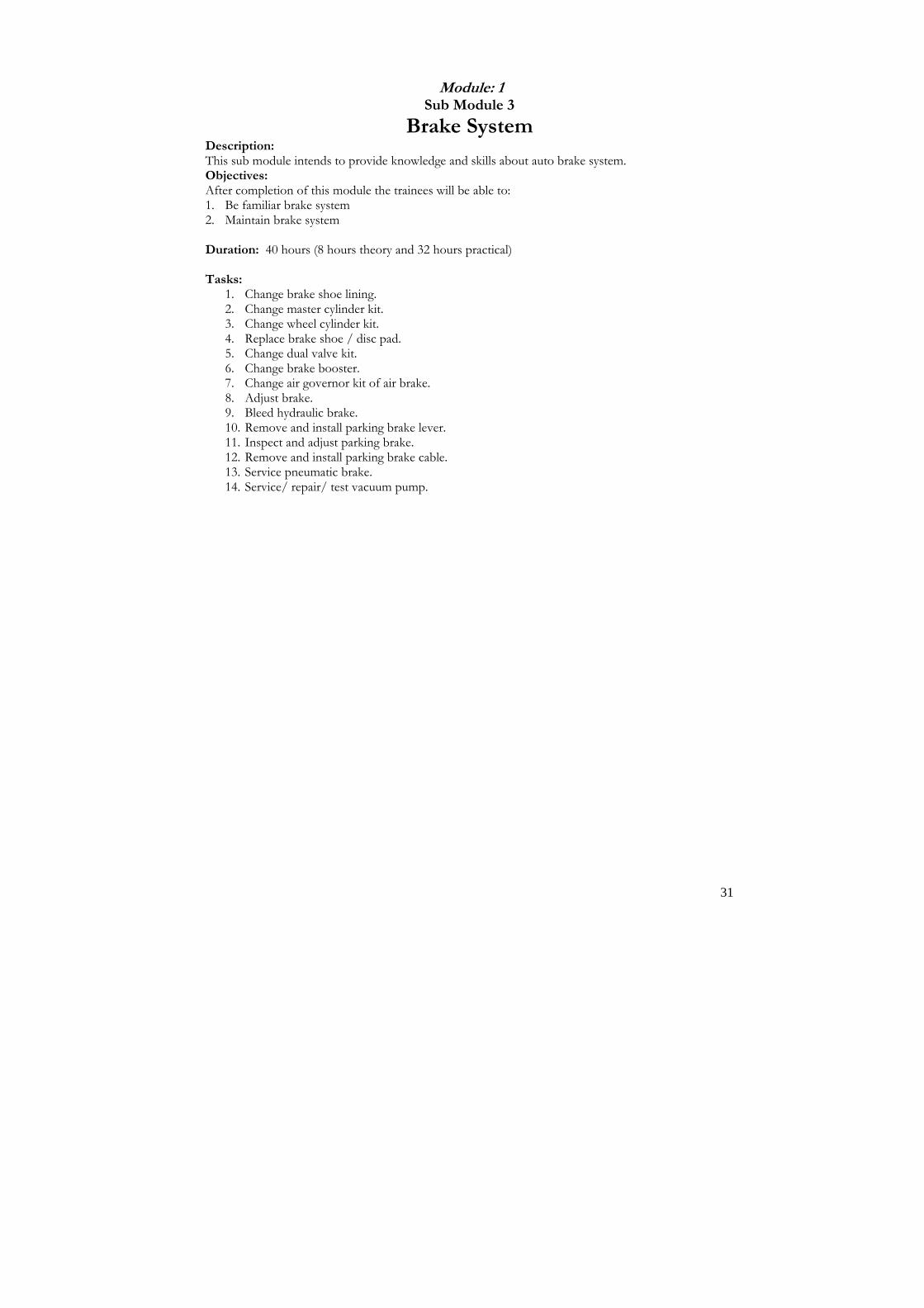
Module: 1 Sub Module 3
Brake System Description: This sub module intends to provide knowledge and skills about auto brake system. Objectives: After completion of this module the trainees will be able to: 1. Be familiar brake system 2. Maintain brake system Duration: 40 hours (8 hours theory and 32 hours practical) Tasks:
1. Change brake shoe lining. 2. Change master cylinder kit. 3. Change wheel cylinder kit. 4. Replace brake shoe / disc pad. 5. Change dual valve kit. 6. Change brake booster. 7. Change air governor kit of air brake. 8. Adjust brake. 9. Bleed hydraulic brake. 10. Remove and install parking brake lever. 11. Inspect and adjust parking brake. 12. Remove and install parking brake cable. 13. Service pneumatic brake. 14. Service/ repair/ test vacuum pump.

32
Task No: 1 Change brake shoe lining.
Performance steps Terminal Performance Objectives
Related Technical Knowledge
1. Apply hand brake or choke the wheel 2. Place the jack to the frame or support near
to the wheel. 3. Loosen the wheel nut.
4. Lift the jack to make the wheel free from ground.
5. Remove the wheel nut and wheel. To change the pads of disc type brake:
1. Withdraw the strut pin of brake pad if the brake is disc type.
2. Remove the brake pads. 3. Insert the new brake pad to the caliper.
4. Lock the strut pin. To change the brake shoe of drum type brake:
1. Remove the brake drum. 2. Remove the brake shoe return/retracting
spring.
3. Remove brake shoe hold down pin, spring and caps assembly.
4. Change the new brake shoes. 5. Clamp the shoe by using shoe hold down
pin, spring and caps.
6. Insert the brake shoe return springs to their proper order.
7. Adjust the brake shoe adjuster cam or screw. 8. Refit the brake drum.
9. Tight the screws of brake drum.
6. Adjust brake if required. 7. Fit the wheel.
8. Remove the jack.
9. Tighten the wheel nuts in cross method.
Condition (Given): A serviceable vehicle in a workshop. Task (What): Change brake shoe. Standard (How well): The pad of disc type brake changed. The brake shoe of drum type brake changed.
� Importance and
working principle of brake
� Types of brake, shoe and lining
� Trouble shooting of brake system.
� Safety precautions
Safety:
� Observe all safety rules while lifting or working under vehicle. � Always ensure that wheels remaining on ground are firmly chocked. � Never work on a vehicle supported only on jacks. � Use care when removing and replacing brake components to avoid bodily injury. � Use care when working with mechanic's tools to avoid injury. � Don't use compressed air to clean back plate. This creates a hazard by forcing any
asbestos dust into the atmosphere. � Use care when removing and replacing shoe return springs to avoid bodily injury. � Maintain clean and orderly work area.

33
Task No: 2 Change Master cylinder kits.
Performance steps Terminal Performance Objectives
Related Technical Knowledge
1. Locate the manufacturer's information on the vehicle requiring the removal and replacement of MC kit.
2. Open the front bonnet or engine hood.
3. Drain the brake fluid. 4. Remove all components to gain access
to remove the master cylinder.
5. Remove master cylinder assembly. 6. Dismantle master cylinder.
7. Examine the parts for wear.
8. Check the cylinder bore for wear, out of round (oval) or taperness.
9. Measure the cylinder bore diameter. 10. Note the reading.
11. Look up service manual for specifications.
12. Perform honing work if the necessary.
13. Get new parts, kit or assembly to replace the master/wheel cylinder.
14. Reassemble the master cylinder as per service manual's procedure.
15. Replace master cylinder.
16. Replace all components that were removed to gain access to MC.
17. Fill brake fluid to master cylinder.
18. Perform brake bleeding.
19. Check all work. 20. Road test vehicle to check performance.
Condition (Given): A serviceable a vehicle. Task (What): Change master cylinder kit. Standard (How well): The master cylinder kit replaced following the manufacturer's procedure and specifications. The brakes adjusted, bleed and performed with effective and efficient braking action.
� Interpretation of
service manuals � Importance, purpose
and function of brake master cylinders
� Technical terms associated with master cylinder
� Operating principles, functions and types of master cylinder
� Master cylinder measuring, inspecting and honing process.
� Trouble shooting � Safety precautions
Required tools/equipment: Mechanic's hand tools set, Manufacturer's service manual, jack, safety stands, dial gauge, bleeder wrench, transparent pipe jar, etc. Safety:
� Use care when removing and replacing master cylinder to avoid bodily injury. � Use care when working with mechanic's tools to avoid injury. � Don't submerged rubber bucket and seal to kerosene or solvent. � Maintain clean and orderly work area.

34
Task No: 3 Change wheel cylinder kit.
Performance steps Terminal Performance Objectives
Related Technical Knowledge
1. Locate the manufacturer's information on the vehicle requiring the removal and replacement of MC/WC kit.
2. Jack up wheels and place jack stands.
3. Remove wheels.
4. Drain the brake fluid. 5. Remove brake drum.
6. Remove brake return springs, shoes and other parts to gain access to remove the wheel cylinder from brake back plate.
7. Remove wheel cylinder.
8. Dismantle wheel cylinder.
9. Keep the parts of each wheel cylinder separately.
10. Examine the parts for wear. 11. Check the cylinder bore for wear, out
of round (oval) or taperness.
12. Perform honing work if the necessary. 13. Get new parts, kit or assembly to
replace the wheel cylinders.
14. Reassemble the wheel cylinder as per service manual.
15. Replace wheel cylinders. 16. Replace all components that were
removed to gain access to WC.
17. Adjust brakes if necessary. 18. Fill brake fluid to master cylinder.
19. Perform brake bleeding.
20. Replace wheels and tyres. 21. Check all work. 22. Lower vehicle. 23. Road test vehicle to check
performance.
Condition (Given): A serviceable a vehicle. Task (What): Change wheel cylinder kit. Standard (How well): The master cylinder or wheel cylinders kit replaced following the manufacturer's procedure and specifications. The brakes adjusted, bleed and performed with effective and efficient braking action.
� Interpretation of
service manuals � Importance, uses and
identification of wheel cylinders
� Working principles, functions and types of wheel cylinders
� Technical terms associated with wheel cylinders
� Brake adjusting and bleeding process.
� Trouble shooting
Required tools/equipment: Mechanic's hand tools set, Manufacturer's service manual, jack, safety stands, dial gauge, bleeder wrench, transparent pipe jar, etc. Safety:
� Observe all safety rules while lifting or working under vehicle. � Always ensure that wheels remaining on ground are firmly chocked. � Never work on a vehicle supported only on jacks. � Use care when removing and replacing return spring to avoid bodily injury. � Use care when working with mechanic's tools to avoid injury. � Don't submerged rubber bucket and seal to kerosene or solvent. � Maintain clean and orderly work area

35
Task No: 4 Replace brake shoe / disc pad.
Performance steps Terminal Performance Objectives
Related Technical Knowledge
Brake shoe replacement
1. Jack up vehicle and support on stands.
2. Slacken adjusters fully.
3. Remove brake drum.
4. Note exact position of all components to ensure correct reassembly.
5. Remove shoe hold down pin and springs.
6. Remove both shoes and pull–off the return springs.
7. Retain cylinder pistons in place using a strong elastic band to prevent brake fluid leakage.
8. Clean back plate.
9. Check wheel cylinder for free operation.
10. Check adjusters for freedom of movement, lubricate if necessary.
11. Check wheel hub for oil leakage. Rectify if necessary.
12. Prepare replacement shoes and pull-off springs for fitting.
13. Reassemble brake shoes in the reverse order of removal.
Disc pad replacement:
1. Jack up vehicle and support on stands.
2. Remove road wheels.
3. Remove split pins and spring retaining clips.
4. Remove worn pad.
5. Check disc for scoring and /or damage.
6. Push operating pistons as far as possible into cylinder bores.
7. Insert new pads and ensure that they are correctly positioned.
8. Fit new spring retaining clips and split pins.
9. Operate brake pedal until correct operation is achieved.
10. Check fluid level, replenish if necessary.
Condition (Given): A serviceable vehicle in a workshop. Task (What): Replace brake shoe or disc pad. Standard (How well): The brake shoe or disc pad replaced and adjusted according to manufacturer's procedures and specifications.
� Importance and
identification of brake and their components.
� Types of brake � Importance and
properties of brake/clutch fluid.
� Trouble shooting of brake
� Safety precautions
Safety: � Observe all safety rules while lifting or working under vehicle. � Always ensure that wheels remaining on ground are firmly chocked. � Never work on a vehicle supported only on jacks. � Don't use compressed air to clean back plate. This creates a hazard forcing any asbestos
dust into the atmosphere. � Use care when removing and replacing return spring to avoid bodily injury.

36
Task No: 5 Change dual valve kit.
Performance steps Terminal Performance Objectives
Related Technical Knowledge
1. Locate the manufacturer's information on the vehicle requiring the removal and replacement of duel valve kit.
2. Raise vehicle and place safety stands under frame.
3. Drain the brake fluid.
4. Remove all components to gain access to remove the dual valve from the vehicle.
5. Disconnect all brake pipelines from dual valve.
6. Remove the duel valve from chassis. 7. Dismantle duel valve as per
manufacturer's procedures. .
8. Clean all the parts. Don't wash the rubber seal and o-rings in solvent.
9. Examine the parts for wear. 10. Check the cylinder bore and for wear. 11. Look up service manual for
specifications. 12. Get new parts, kit or assembly to replace
the duel valve. 13. Reassemble duel valve.
14. Replace all components that were removed to gain access to duel valve.
15. Check all work.
Condition (Given): A serviceable a vehicle. Task (What): Change duel valve kit. Standard (How well): The duel valve kit replaced following the manufacturer's procedure and specifications. The brake performed effective and efficient braking action.
� Interpretation of
service manuals � Importance, types and
parts of duel valve � Technical terms
associated with duel valve
� Working principles and functions of duel valve
� Trouble shooting � Safety precautions
Required tools/equipment: Mechanic's hand tools set, Manufacturer's service manual, jack, safety stands, dial gauge, bleeder wrench, transparent pipe jar, etc. Safety:
� Observe all safety rules while lifting or working under vehicle. � Always ensure that wheels remaining on ground are firmly chocked. � Never work on a vehicle supported only on jacks. � Use care when removing and replacing return spring to avoid bodily injury. � Use care when working with mechanic's tools to avoid injury. � Don't submerged rubber bucket and seal to kerosene or solvent. � Maintain clean and orderly work area.

37
Task No: 6 Change brake booster.
Performance steps Terminal Performance Objectives
Related Technical Knowledge
1. Locate the manufacturer's information on the vehicle requiring the removal and replacement of brake booster.
2. Lift the bonnet.
3. Remove all components to gain access to brake booster.
4. Disconnect brake hosepipe.
5. Loosen securing bolts or nuts to master cylinder and brake booster.
6. Remove master cylinder. 7. Remove brake booster assembly.
8. Unlock the brake booster securing plate.
9. Disassemble the brake booster. 10. Examine the diaphragm, push rod for
wear and tear.
11. Get new parts, diaphragm or new booster assembly for replacement.
12. Reassemble the brake booster. 13. Install booster and master cylinder.
14. Replace all components that were removed to gain access to booster.
15. Check and complete all work.
Condition (Given): A serviceable a vehicle. Task (What): Change brake booster. Standard (How well): The brake booster replaced as per manufacturer's procedure and specifications. The brake pressed in minimum pedal effort without spongy.
� Interpretation of
service manuals � Importance,
identification, types and parts of brake.
� Technical terms associated with brake booster
� Operating principles and functions of brake booster
� Trouble shooting � Safety precautions
Required tools/equipment: Mechanic's hand tools set, Manufacturer's service manual, jack, safety stands, bleeder wrench, transparent pipe jar, etc. Safety:
� Observe all safety rules while lifting or working under vehicle. � Always ensure that wheels remaining on ground are firmly chocked. � Never work on a vehicle supported only on jacks. � Use care when working with mechanic's tools to avoid injury. � Don't submerged rubber bucket and seal to kerosene or solvent. � Maintain clean and orderly work area.

38
Task No: 7 Change air governor kit of air brake.
Performance steps Terminal Performance Objectives
Related Technical Knowledge
1. Determine the types of brake and service to be performed.
2. Locate the air valve or governor mounted on the chassis.
3. Remove all the sheet metal or hardware to gain access to remove air governor.
4. Remove air from braking system.
5. Disconnect air pipe from air governor.
6. Remove the air governor. 7. Disassemble the governor as per
manufacturer's procedures.
8. Check the parts for wear. 9. Get new parts, kit or replacement of air
governor. 10. Replace the air governor. 11. Connect the air pipe to the air governor. 12. Replace all the parts that were removed to
gain access the air governor.
13. Check and test the performance.
Condition (Given): A vehicle equipped with air brake system. Task (What): Change air governor kit. Standard (How well): The air governor/valve replaced as per manufacturer's procedures and specifications.
� Interpretation of
service manual. � Identification, uses
and parts of air brake system
� Working principles and functions of air brake system and air governor
� Technical terms associated with air brake system.
� Cause and effects of air brake malfunction
� Trouble shooting � Safety precautions
Required tools/equipment: Mechanics' hand tools set, drain plug wrench, tray/jar, filler pipe, and
funnel Safety:
� Observe all safety rules while lifting or working under vehicle. � Always ensure that wheels remaining on ground are firmly chocked. � Never work on a vehicle supported only on jacks. � Don't use compressed air to clean back plate. This creates a hazard forcing any asbestos
dust into the atmosphere. � Use care when removing and replacing return spring to avoid bodily injury. � Use care when working with mechanic's tools to avoid injury. � Maintain clean and orderly work area.

39
Task No: 8 Adjust brake.
Performance steps Terminal Performance Objectives
Related Technical Knowledge
Brake shoe adjustment:
8. Jack up vehicle until wheel to be adjusted is just clear of ground.
9. Clear dirt from adjusters and surrounding. 10. Turn each adjuster in clockwise direction
until the brake shoes lock the brake drum. 11. Slacken off adjuster until wheel spins
freely.
12. Repeat on remaining wheels. NOTE: Ensure that the hand brake has been released before adjusting the rear wheel brakes. Hand brake adjustment:
1. Jack up vehicle until rear wheels are clear of the ground.
2. Support on the axle stands.
3. Release hand brake.
4. Check manufacturer's instructions before adjusting hand brake.
NOTE: On some vehicle the hand brake cable can be adjusted at the rear of the hand brake lever. Always consult manufacturer's manual before commencing any adjustment.
5. Adjust hand brake cable adjuster until the shoes contact with the drum.
6. Slacken adjuster sufficiently to allow the wheel to rotate freely.
7. Check hand brake linkage for wear.
8. Adjust and lubricate as necessary.
Condition (Given): A serviceable vehicle in a workshop. Task (What): Adjust brake shoe or hand brake. Standard (How well): The brake shoe and hand brake adjusted within 15 +- 5 mm pedal free play. The vehicle stopped in minimum braking distance.
� Identify the parts
and uses of braking system and their components
� Types of brake. � Explain the working
principles and functions of hand brake
� Identify and demonstrate the methods of adjusting brake.
� Trouble shooting of brake system
� Safety precautions
Required tools/equipment: Mechanics' hand tools set, break adjusting tool or screwdriver, Brake
bleeding pipe, Jar etc. Safety:
� Observe all safety rules while lifting or working under vehicle. � Always ensure that wheels remaining on ground are firmly chocked. � Never work on a vehicle supported only on jacks. � Use care when removing and replacing return spring to avoid bodily injury. � Use care when working with mechanic's tools to avoid injury. � Maintain clean and orderly work area.

40
Task No: 9 Bleed hydraulic brake.
Performance steps Terminal Performance Objectives
Related Technical Knowledge
1. Examine the master cylinder reservoir cap and ensure that the vent hole is clear.
2. Maintain the fluid level in the reservoir; it should be the specified level below the top of the reservoir face.
3. Check all unions and connections for tightness and freedom from leaks and check all the conditions of the flexible hoses.
4. Clean the area around the bleeding nipples.
5. Start bleeding at the nipple furthest from master cylinder and work to the nipple nearest this cylinder.
6. Select any one of the wheel cylinder, which is the longest distance from master cylinder.
7. Insert one end of the clean rubber tube (about 300 mm) over bleeding nipple on the brake back plate
8. Position the free end of the tube in a glass jar partially filled with clean brake fluid; ensure the tube end is submerged in the fluid.
9. Press the brake pedal and unscrew bleed nipple half a turn.
10. Check whether air bubbles are escaped through the tube, assistant should then press brake pedal firmly to floor.
11. Close the nipple and release pedal quickly. 12. Repeat Performance steps 9 to 11 until all
air is expelled from the system. 13. Close the bleed nipple when only brake
fluid is pumped out with the pedal fully operated depressed.
14. Check fluid reservoir level frequently during this operation.
15. Remove the tube and repeat the operation on the other three wheels.
16. Check the fluid level on master cylinder during the bleeding operations on the other three wheels.
17. Fill the level; use only the brake fluid recommended for the vehicle being worked on.
18. Adjust brake to correct setting and check position when all wheels have bleed.
Condition (Given): A serviceable vehicle in a workshop. Task (What): Bleed air from brake. Standard (How well): The air bubble free from brake and the brake fluid should be in specified level.
� Interpretation of
service manual � Importance of
brake bleeding � Properties of brake
fluid � Brake bleeding and
adjustment process. � Grade, viscosity and
full form of DOT, SAE and API number
� Trouble shooting
Safety: � Observe all safety rules while lifting or working under vehicle. � Always ensure that wheels remaining on ground are firmly chocked. � Never work on a vehicle supported only on jacks.

41
Task No: 10 Remove and install parking brake lever.
Performance steps Terminal Performance Objectives
Related Technical Knowledge
Removal 10. Hoist vehicle and release parking brake
lever
11. Disconnect negative cable at battery 12. Disconnect lead wire of parking brake
switch and coupler 13. Loosen parking brake cable stopper nut
and remove adjusting nut
14. loosen parking brake cable bracket nut and remove parking brake cable from bracket
15. Remove parking brake lever bolts and then remove parking brake lever assembly.
Installation:
5. Install reverse order of removal procedure.
6. After all parts are installed, parking brake lever needs to be adjusted.
7. Check brake drum for dragging and brake system for proper performance
Condition (Given): A serviceable vehicle in a workshop. Task (What): Remove and install parking brake lever. Standard (How well): The bolts need to be tighten as per the specification (tightening torque)
� Importance and
working principle of parking brake
� Parts related to parking brake
� Trouble shooting of parking brake system.
� Safety precautions
Required tools/equipment: Mechanic's hand tools set, Manufacturer's service manual, jack, safety stands, torque wrench etc. Safety:
� Observe all safety rules while lifting or working under vehicle. � Always ensure that wheels remaining on ground are firmly chocked. � Never work on a vehicle supported only on jacks. � Use care when removing and replacing brake components to avoid bodily injury. � Use care when working with mechanic's tools to avoid injury. � Maintain clean and orderly work area.

42
Task No: 11 Inspect and adjust parking brake.
Performance steps Terminal Performance Objectives
Related Technical Knowledge
Inspection 1. Hold center of parking brake lever grip and pull it to specified force
2. With parking brake lever pulled up as above, count ratchet notch
3. It should be 5 to 8 notches 4. Check both left and right wheels are locked firmly
5. If number of notches is out of specification, adjust cable.
Adjustment: 1) Ensure the following condition of cable
• No air is trapped in brake system
• Brake pedal travel is proper
• brake pedal has been depressed a few times without specified force
• Parking brake lever has been pulled up a few times with specified force
• Rear shoes are not worn beyond limit and self adjustment mechanism operates properly
2) confirming all above, adjust parking brake lever stroke by loosening or tightening adjusting nut
Condition (Given): A serviceable vehicle in a workshop. Task (What): Inspect and adjust parking brake Standard (How well): Click noise that ratchet makes while pulling parking brake lever without pressing its button to be listened to count no. of notch easily For cable adjustment, stopper nut to be loosened and turned adjusting nut while holding nut with spanner so as to prevent inner cable from getting twisted Brake drum to be checked for dragging after adjustment
� Importance and
working principle of parking brake
� Trouble shooting of parking brake system.
� Safety precautions
Required tools/equipment: Mechanic's hand tools set, Manufacturer's service manual, jack, safety stands, torque wrench etc. Safety:
� Observe all safety rules while lifting or working under vehicle. � Always ensure that wheels remaining on ground are firmly chocked. � Never work on a vehicle supported only on jacks. � Use care when removing and replacing brake components to avoid bodily injury. � Use care when working with mechanic's tools to avoid injury. � Maintain clean and orderly work area.

43
Task No: 12 Remove and install parking brake cable.
Performance steps Terminal Performance Objectives
Related Technical Knowledge
Removal 1. Raise suitably support vehicle and remove wheel if necessary
2. Remove parking brake cable Installation:
8. Install it by reversing removal procedure, noting the following points
9. Install clamps properly
10. Tighten bolts and nuts to specified torque 11. Upon completion of installation, adjust
cable
Condition (Given): A serviceable vehicle in a workshop. Task (What): Remove and install parking brake cable. Standard (How well): The bolts need to be tighten as per the specification (tightening torque)
� Importance and
working principle of parking brake
� Operation of parking brake cable
� Trouble shooting of parking brake system.
� Safety precautions
Required tools/equipment: Mechanic's hand tools set, Manufacturer's service manual, jack, safety stands, torque wrench etc. Safety:
� Observe all safety rules while lifting or working under vehicle. � Always ensure that wheels remaining on ground are firmly chocked. � Never work on a vehicle supported only on jacks. � Use care when removing and replacing brake components to avoid bodily injury. � Use care when working with mechanic's tools to avoid injury. � Maintain clean and orderly work area.

44
Task No: 13 Service pneumatic brake.
Performance steps Terminal Performance Objectives
Related Technical Knowledge
1. Drain off condense water 2. Grease with grease gun brake pedal
bushing, brake double lever, slack adjuster 3. Lubricate with oil can brake chamber fork
and pin, linkages of foot brake ball joints of exhaust brake linkages
4. Check free movement of plunger in dual brake valve
5. Check brake system for leaks and rectify if necessary
6. Check travel of brake chamber’s push rod/ brake lining wear and clearance with drum
7. Check proper functioning of engine exhaust brake, free movement of plunger of exhaust brake valve, mounting bolts and slackness in linkages
8. Check for hose damages and replace if necessary
9. Check brake torque plate mounting bolts and tighten if necessary
10. Check condition of gaiter in different brake valves, exhaust flap in dual brake valve, nylon breather tube and clips of spring brake actuator
11. Check mounting bolts of brake chambers, different valve mountings, air tank mountings, air line clamps and tighten if necessary
12. Remove brake drums, inspect brake linings, brake drums
13. Remove filter element in serviceable type air filter, clean and refit
Condition (Given): A serviceable vehicle in a workshop. Task (What): Service pneumatic brake Standard (How well): The bolts need to be tighten as per the specification (tightening torque)
� Principle of
pneumatic brakes � Aggregate related to
pneumatic brakes � Interpretation of
service manual � Properties of grease
Required tools/equipment: Mechanic's hand tools set, Manufacturer's service manual, jack, safety stands, torque wrench etc. Safety:
� Observe all safety rules while lifting or working under vehicle. � Always ensure that wheels remaining on ground are firmly chocked. � Never work on a vehicle supported only on jacks. � Use care when removing and replacing brake components to avoid bodily injury. � Use care when working with mechanic's tools to avoid injury. � Maintain clean and orderly work area.

45
Task No: 14 Service/ repair/ test vacuum pump.
Performance steps Terminal Performance Objectives
Related Technical Knowledge
Removal 1. Disconnect vacuum hose 2. Disconnect oil outlet hose 3. Remove pump mounting bolts 4. Remove the pump 5. Remove oil seal Disassembly of vacuum pump 1. Remove vacuum hose union and check
valve 2. Remove oil outlet hose union 3. Tap pin down and remove end plate 4. Remove O- Ring 5. Remove rotor and blades Inspection 1. Inspect blade for wear or damage 2. Inspect check valve operation. Check that
air flows from the hose side to the pump side. Also check air does not flow from pump side to the hose side
3. Inspect bushing and oil seal for wear or oil leakage at end frame of alternator
Assembly 1. Install rotor into casing 2. Install blades with round end facing
outward 3. Install a new O-Ring and end plate 4. Install check valve Installation: 1. Install new oil seal. 2. Install pump 3. Connect oil outlet hose 4. Install union to check valve 5. connect vacuum hose 6. check pump for operation
Condition (Given): A serviceable vehicle in a workshop. Task (What): Overhaul vacuum pump. Standard (How well): The bolts need to be tighten as per the specification (tightening torque). Oil seal to be used new.
� Working principle
of vacuum pump. � Trouble shooting of
vacuum pump. � Safety precautions. � Interpretation of
service manual
Required tools/equipment: Mechanic's hand tools set, Manufacturer's service manual, jack, safety stands, torque wrench etc. Safety:
� Always ensure that wheels remaining on ground are firmly chocked. � Never work on a vehicle supported only on jacks. � Use care when removing and replacing brake components to avoid bodily injury. � Use care when working with mechanic's tools to avoid injury. � Maintain clean and orderly work area.

46
Module: 1 Sub Module 4
Steering System Description: This sub module intends to provide knowledge and skills about auto steering system. Objectives: After completion of this module the trainees will be able to: 1. Be familiar with steering system 2. Maintain steering system Duration: 30 hours (6 hours theory and 24 hours practical) Tasks:
1. Change ties rod end/ball joints. 2. Change steering universal cross. 3. Remove/ replace steering gearbox. 4. Repair steering gearbox. 5. Change steering oil. 6. Change kingpin. 7. Change steering wheel/bush. 8. Replace rack bush. 9. Replace knuckle oil seal. 10. Repair/ change hydraulic steering kit. 11. Repair front axle.

47
Task No: 1 Change tie rod end/ball joints.
Performance steps Terminal Performance Objectives
Related Technical Knowledge
1. Locate the manufacturer's information on the vehicle requiring the removal and replacement of tie rod end.
2. Raise the car if necessary and place safety stands under frame.
3. Loosen the lower nut of tie rod end or ball joint.
4. Turn the steering wheel to access to work on tie rod end.
5. Remove tie rod end or ball joint by using puller or gently hammering the pitman/steering arm or tie rod.
6. Loosen the tie rod end from tie rod shaft.
7. Remove the ball joints or tie rod end.
8. Replace the new tie rod end or ball joints.
9. Tighten the ball joints nuts. 10. Check all work. 11. Lower vehicle and remove jack stands.
Condition (Given): A serviceable vehicle. Task (What): Change tie rod end. Standard (How well): The tie rod ends removed and replaced following the manufacturer's procedure and the steering should not be hard and free from vibration and noise.
� Interpretation of
service manuals � Importance,
identification and types of steering system
� Working principles function and parts of steering
� Technical terms associated with steering system and steering geometry.
� Trouble shooting
Required tools/equipment: Mechanic's hand tools set, Manufacturer's service manual, jack, ball joint puller, safety stands, etc. Safety:
� Observe all safety rules while lifting or working under vehicle. � Always ensure that wheels remaining on ground are firmly chocked. � Never work on a vehicle supported only on jacks. � Use care when working with steering system to avoid bodily injury. � Use care when working with mechanic's tools to avoid injury. � Maintain clean and orderly work area.

48
Task No: 2 Change steering universal cross.
Performance steps Terminal Performance Objectives
Related Technical Knowledge
1. Place vehicle on lift and rise.
2. Mark steering shaft and flange yoke relationship before removing so it may be put back the same way.
3. Remove bolts or nuts from flange on universal joint cross.
4. Remove universal joint cross.
5. Remove u-joints clips, snap rings or locking devices.
6. Remove cups from u-joints. 7. Clean all parts, except seals, in solvent and
dry.
8. Inspect bearings and seals for damage or wear.
9. Press bearings free of yoke and flange. 10. Replace new or replacement cross-joint.
11. Pack the bearings with grease.
12. Replace universal joints cross. 13. Replace clips, snap rings or locking
devices.
14. Align mark on drive shaft with mark on yoke and replace steering shaft in vehicle.
15. Reinstall rubber damper and universal joint cross in flange on steering shaft.
16. Check all work.
17. Lower vehicle.
Condition (Given): A serviceable steering of a vehicle. Task (What): Remove/replace universal joint cross. Standard (How well): The universal joint replaced and moved freely and the steering shaft functioned without excessive noise or vibration at any speed.
� Interpretation of
service manuals � Importance, uses
and identification of universal joints
� U-joint removing and replacing process.
� Function of universal joints.
� Causes and effects of U- joints malfunctioning.
� Trouble shooting
Required tools/equipment: Mechanic's hand tools set, Manufacturer's service manual, safety stands, bench vice, arbor press, u-joint press, dial indicator, etc. Safety:
� Observe all safety rules while lifting or working under vehicle. � Always ensure that wheels remaining on ground are firmly chocked. � Never work on a vehicle supported only on jacks. � Use care when removing and replacing universal joints to avoid bodily injury. � Use care when working with mechanic's tools to avoid injury. � Maintain clean and orderly work area.

49
Task No: 3 Remove/replace steering gearbox.
Performance steps Terminal Performance Objectives
Related Technical Knowledge
1. Determine the types of steering gearbox and follow the service manual for servicing.
2. Remove steering wheel nut cap and nut.
3. Remove steering wheel by using puller. 4. Remove all parts/components to gain
access to remove steering gear box.
5. Remove pitman arm/drop arm from cross shaft.
6. Remove worm shaft to steering shaft universal joint.
7. Remove steering gear housing to frame fasteners and pull gearbox housing.
8. Clean the exterior of the gearbox housing thoroughly and remove the cover.
9. Drain steering gear oil. 10. Disconnect the pitman/steer shaft
adjusting screw from the pitman shaft.
11. Pull the pitman shaft/cross shaft from the housing.
12. Loosen the worm bearing adjuster lock and remove adjuster and worm gear shaft or steering shaft.
13. Clean all parts with solvent.
14. Inspect bearings, cups and worm shaft bearing surface.
15. Check pitman shaft and worm shaft for wear.
16. Get new or replaced parts as needed.
Condition (Given): A serviceable steering of a vehicle. Task (What): Remove/replace steering gear box. Standard (How well): The steering gear box removed according to manufacturer's procedure and specifications.
� Interpretation of
service manuals � Importance,
purpose, function and types of steering system.
� Technical terms associated with steering gearbox
� Working principles, functions and types of steering gearbox.
� Causes and effects of steering gear box malfunctioning
� Trouble shooting
Required tools/equipment: Mechanic's hand tools set, Manufacturer's service manual, safety stands, bench vice, arbor press, u-joint press, dial indicator, etc. Safety:
� Observe all safety rules while lifting or working under vehicle. � Always ensure that wheels remaining on ground are firmly chocked. � Never work on a vehicle supported only on jacks. � Use care when removing and replacing steering gearbox to avoid bodily injury. � Use care when working with mechanic's tools to avoid injury. � Maintain clean and orderly work area.

50
Task No: 4 Repair steering gearbox.
Performance steps Terminal Performance Objectives
Related Technical Knowledge
1. Clean all parts of the steering gearbox after disassembly.
2. Install bearing cone, ball bearings, worn shaft and bearing adjuster.
3. Run adjuster up just fit enough to hold worm shaft bearing in position.
4. Lubricate all parts with recommended lubricant prior to assembly.
5. Install pitman shaft or cross shaft. 6. Turn the worm shaft from extreme right
to extreme left. Don't force against Performance steps. Movement should be smooth with no roughness or binding.
7. Provide shim according to endplay of the pitman shaft or cross shaft.
8. Place cover gasket in place.
9. Hold the housing in normal operating position.
10. Fill gear oil with approved lubricant.
11. Install gearbox assembly on the vehicle.
12. Torque fasteners. 13. Check gear housing to steering shaft
alignment. 14. Connect pitman arm and other linkage
steering wheel and steering column.
Condition (Given): A serviceable steering of a vehicle. Task (What): Repair steering gearbox. Standard (How well): The steering gearbox repaired and replaced as per manufacturer's procedures and specifications. The steering steered the vehicle and control directional stability without noise or vibration.
� Interpretation of
service manuals. � Types and parts
identification of steering gearbox.
� Technical terms associated with steering gearbox.
� Gearbox overhauling process.
� Working principles and function of steering gearbox.
� Causes and effects of gearbox failure.
� Trouble shooting. � Safety
precautions.
Required tools/equipment: Mechanic's hand tools set, Manufacturer's service manual, safety stands, bench vice, feeler gauge, slide hammer etc. Safety:
� Observe all safety rules while lifting or working under vehicle. � Never work on a vehicle supported only on jacks. � Use care when repairing steering gearbox to avoid bodily injury. � Use care when working with mechanic's tools to avoid injury. � Maintain clean and orderly work area.
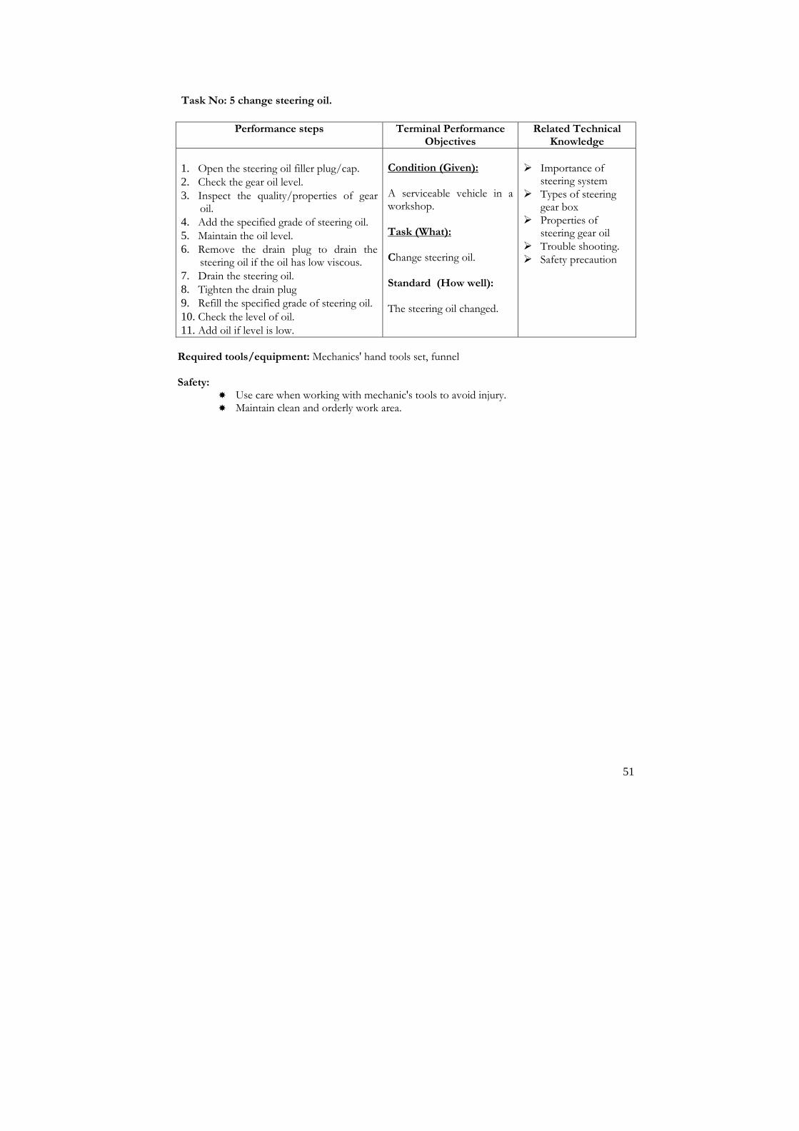
51
Task No: 5 change steering oil.
Performance steps Terminal Performance Objectives
Related Technical Knowledge
1. Open the steering oil filler plug/cap. 2. Check the gear oil level.
3. Inspect the quality/properties of gear oil.
4. Add the specified grade of steering oil.
5. Maintain the oil level. 6. Remove the drain plug to drain the
steering oil if the oil has low viscous.
7. Drain the steering oil. 8. Tighten the drain plug
9. Refill the specified grade of steering oil.
10. Check the level of oil. 11. Add oil if level is low.
Condition (Given): A serviceable vehicle in a workshop. Task (What): Change steering oil. Standard (How well): The steering oil changed.
� Importance of
steering system � Types of steering
gear box � Properties of
steering gear oil � Trouble shooting. � Safety precaution
Required tools/equipment: Mechanics' hand tools set, funnel Safety:
� Use care when working with mechanic's tools to avoid injury. � Maintain clean and orderly work area.

52
Task No: 6 Change king pin.
Performance steps Terminal Performance Objectives
Related Technical Knowledge
1. Locate the manufacturer's information on the vehicle requiring the removal and replacement of kingpin.
2. Raise the vehicle and place safety stands under frame.
3. Remove front wheels.
4. Remove tie rod end joints.
5. Remove steering arm.
6. Remove brake mechanism assembly if necessary.
7. Hold the stub axle in parallel to the king pin.
8. Remove the king pin securing cap or lock plate.
9. Lift the king pin upward by using puller or kingpin remover.
10. Clean the parts.
11. Check the king pin shaft and bush for wear.
12. Get new bush and kingpin.
13. Install new bush to king pin housing.
14. Pack grease to the king pin and housing.
15. Install the new king pin and fix the stub axle or spindle to the front axle.
16. Lock the king pin by securing cap or lock plate.
17. Replace tie rod end joints.
18. Replace brake mechanism assembly.
19. Replace all parts that were removed to access the kin pin.
20. Install front wheels.
21. Check all work.
22. Lower vehicle and remove jack stands.
Condition (Given): A serviceable vehicle. Task (What): Change kingpin. Standard (How well): Steering arm removed King pin lifted New bush installed Brake mechanism replaced.
� Interpretation of service
manuals � Types and parts of
steering system. � Technical terms
associated with steering system
� Operating principle and function of king pin.
� Reorganization, analysis and solving or referring to problems
Required tools/equipment: Mechanic's hand tools set, Manufacturer's service manual, jack, ball joint puller, safety stands, etc. Safety:
� Observe all safety rules while lifting or working under vehicle. � Never work on a vehicle supported only on jacks. � Use care when repairing steering gearbox to avoid bodily injury. � Use care when working with mechanic's tools to avoid injury. � Maintain clean and orderly work area.

53
Task No: 7 Change steering wheel/bush.
Performance steps Terminal Performance Objectives
Related Tech1nical Knowledge
1. Disconnect battery negative terminal.
2. Uncover the steering wheel. 3. Remove the check nut to steering wheel.
4. Disconnect the wire or connector from steering wheel.
5. Remove steering wheel by using puller.
6. Check steering wheel bush for wear.
7. Replace new bush if worn. 8. Check the crack or deformation of spoke on
steering wheel.
9. Replace new or replacement steering wheel. 10. Lock the steering wheel by tightening check
nut or woodruff key. 11. Check the steering wheel free play: adjust if
necessary.
12. Connect wires or connector to the steering wheel.
13. Cover the check nut of the steering wheel.
Condition (Given): A serviceable steering of a vehicle. Task (What): Change steering wheel/bush. Standard (How well): The steering wheel or bush changed and the free play adjusted as per specification.
� Importance,
types and parts of steering gearbox
� Technical terms associated with steering
� Wheel plays adjusting process
� Trouble shooting
Required tools/equipment: Mechanic's hand tools set, Manufacturer's service manual, steering wheel puller, slide hammer etc. Safety:
� Use care when repairing steering gearbox to avoid bodily injury. � Use care when working with mechanic's tools to avoid injury. � Maintain clean and orderly work area.

54
Task No: 8 Replace rack bush.
Performance steps Terminal Performance Objectives
Related Technical Knowledge
1. Disconnect tie rod ball joints.
2. Disconnect steering shaft coupling/flange. 3. Disconnect drop arm or steering arm from
rack & pinion steering gear box.
4. Remove steering gear box. 5. Unscrew the rack bush mounting
clamp/clip. 6. Remove rack bushes from both sides.
7. Replace new or replacement rack bushes.
8. Clamp the rack bushes.
9. Check the steering gear free play: adjust if necessary.
10. Inspect the rack & pinion operation by rotating the rack shaft.
11. Fill the steering oil/grease if necessary.
12. Install the steering gear box. 13. Connect the drop arm/steering arm and ball
joints. 14. Check the operation of the steering.
Condition (Given): A serviceable steering of a vehicle. Task (What): Change rack bush. Standard (How well): The rack bushes changed and the free play adjusted as per specification.
� Importance,
types and parts of rack & pinion type steering gearbox
� Technical terms associated with rack & pinion steering
� Wheel plays adjusting process
� Trouble shooting
Required tools/equipment: Mechanic's hand tools set, Manufacturer's service manual, steering wheel puller, slide hammer etc. Safety:
� Use care when repairing steering gearbox to avoid bodily injury. � Use care when working with mechanic's tools to avoid injury. � Maintain clean and orderly work area.

55
Task No: 9 Replace knuckle oil seal.
Steps Terminal Performance Objectives
Related Technical Knowledge
1. Loosen the wheel nuts.
2. Raise the vehicle and rest it on safety stand.
3. Drain differential oil if it is live axle
4. Remove front wheels.
5. Remove brake drum assembly.
6. Remove brake caliper and disc brake if fitted.
7. Hang the caliper with wire to prevent damage of hose. Don't operate brake pedal with caliper removed.
8. Remove cover or cap of free wheeling hub.
9. Remove circlip from axle to remove hub and remove free wheeling hub and drive flange.
10. Straighten bent part of lock washer and use special tool or socket wrench to open wheel bearing lock nut.
11. Remove wheel-bearing nut.
12. Remove front wheel hub.
13. Remove disc dust cover and caliper holder.
14. Remove wheel spindle.
15. Disconnect tie rod end by using tie rod end remover.
16. Remove lower and upper king pin.
17. Keep upper and lower king pins and its bearings separately.
18. Remove knuckle oil seal and retainer.
19. Clean all parts with solvent.
20. Inspect all the parts as per manufacturer's specifications and procedures.
21. Replace new oil seal.
22. Apply grease on axle shaft oil seal and steering knuckle before installation.
23. Put joint seal, oil seal cover, oil seal and retainer on axle housing and install knuckle.
24. Replace kingpin.
25. Install wheel spindle by applying grease on mating surface of shaft and bush of spindle.
26. Replace all the parts that were removed previously in reverse order.
Condition (Given): A serviceable steering of a vehicle. Task (What): Replace knuckle oil seal. Standard (How well): The wheel and brake mechanism removed. Knuckle oil seal replaced as per service manual.
� Interpretation of service
manuals � Identify types and parts
of steering arm and knuckle
� Technical terms associated with front axle and steering
� Operating principles and function of knuckle oil seal.
� Trouble shooting � Safety precautions
Safety: � Observe all safety rules while lifting or working under vehicle. � Never work on a vehicle supported only on jacks. � Use care when working with front axle to avoid injury.

56
Task No: 10 Repair/change hydraulic steering kit.
Steps Terminal Performance Objectives
Related Technical Knowledge
1. Consult manufacturer's service manual to locate the parts to be repair and replacement of given hydraulic steering.
2. Loosen the wheel nuts.
3. Raise the vehicle and rest it on safety stand.
4. Drain hydraulic oil from the steering.
5. Remove front wheels.
6. Remove the parts to gain access to remove steering gear box.
7. Disconnect the hydraulic hoses and clamp from reservoir, hydraulic pump and steering gear box.
8. Remove hydraulic steering pump.
9. Remove steering gear box.
10. Clean the exterior parts of the pump, gearbox and surrounding.
11. Disassemble hydraulic pump and gearbox.
12. Clean all parts with solvent. Don't immersed o-ring or oil seal with solvent.
13. Inspect all the parts as per manufacturer's specifications and procedures.
14. Get new or replacement of parts, oil pump and gearbox assembly.
15. Reassemble the oil pump and gearbox as per manufacturer's procedure and specifications.
16. Install oil pump and steering gear box.
17. Add hydraulic oil to the reservoir.
18. Bleed the hydraulic system.
19. Refill oil if necessary.
20. Connect all hoses and filter to the steering system.
21. Replace all parts that were removed to gain access the hydraulic pump and gearbox.
22. Install front wheels.
Condition (Given): A serviceable steering of a vehicle. Task (What): Repair/change hydraulic steering kit. Standard (How well): Hydraulic hoses and clamp disconnected. Hydraulic steering pump removed and repair kit replaced. Hydraulic systems bleed.
� Interpretation of
service manuals � Importance,
advantages and types of hydraulic steering
� Working principles and functions of hydraulic steering
� Technical terms associated with hydraulic steering gearbox
� Working principles and functions of hydraulic pump and gearbox
� Trouble shooting. � Safety precautions
Safety:
� Observe all safety rules while lifting or working under vehicle. � Never work on a vehicle supported only on jacks. � Use care when working with hydraulic steering to avoid injury. � Always bleed the hydraulic system after completion of repairing work. � Use care when working with mechanic's hand tools. � Maintain clean and orderly work area

57
Task No: 11 Repair front axle.
Steps Terminal Performance Objectives
Related Technical Knowledge
1. Determine the types of front axle.
2. Drain differential oil if it is live axle
3. Remove front wheels.
4. Remove brake drum/caliper assembly.
5. Hang the caliper with wire to prevent damage.
6. Remove cover or cap of free wheeling hub.
7. Remove circlip from axle to remove hub and remove free wheeling hub and drive flange.
8. Remove wheel-bearing nut.
9. Remove front wheel hub.
10. Remove disc dust cover and caliper holder.
11. Remove wheel spindle.
12. Disconnect tie rod end or ball joints.
13. Remove oil seal cover, oil seal and retainer.
14. Remove lower and upper kingpin.
15. Keep upper and lower kingpins and its bearings separately.
16. Remove front axle shafts.
17. Clean all parts with solvent.
18. Inspect all the parts.
19. Install front axle shafts.
20. Check axle play.
21. Apply grease on axle shaft oil seal and steering knuckle before installation.
22. Put joint seal, oil seal cover, oil seal and retainer on axle housing and install knuckle.
23. Replace king pins and shims.
24. Install wheel spindle by applying grease on mating surface of shaft and bush of spindle.
25. Replace caliper holder, disc and disc cover.
26. Install wheel hub and adjust bearing preload.
27. Put washer and tighten the wheel bearing.
28. Keep the hub at free position and cover.
29. Replace caliper assembly.
30. Replace all parts that were removed to gain access to front axles.
31. Fill differential oil after replacing wheels.
Condition (Given): A serviceable steering of a vehicle. Task (What): Repair front axle. Standard (How well): The front axle and steering changed and the wheel bearing free play adjusted as per specification.
� Interpretation of
service manuals � Importance,
identification, types and parts of front (live/dead) axle
� Working principle and functions of front axle
� Technical terms associated with front axle
� Trouble shooting � Safety precautions
Safety: � Observe all safety rules while lifting or working under vehicle. � Never work on a vehicle supported only on jacks. � Use care when working with front axle to avoid injury. � Use care when working with mechanic's hand tools. � Maintain clean and orderly work area.

58
Module: 1 Sub Module 5
Wheel and Tyre Description: This sub module intends to provide knowledge and skills about auto wheel and tyre system. Objectives: After completion of this module the trainees will be able to: 1. Be familiar with maintaining and repairing of wheel and tyre 2. Maintain and repair wheel and tyre Duration: 15 hours (3 hours theory and 12 hours practical) Tasks:
1. Rotate tyre. 2. Change tubeless tyres. 3. Repair tube puncture (flat tyre). 4. Repair tubeless tyre puncture. 5. Change rim disc plate. 6. Balance wheel

59
Task No: 1 Rotate tyre.
Performance steps Terminal Performance Objectives
Related Technical
Knowledge
1. Follow the service manual for the tyre rotation.
2. Lift the vehicle. 3. Apply hand brakes or support the vehicle.
4. Check the tyre pressure.
5. Be sure that the all tyres are same size and ply.
6. Remove tyres.
7. Rotate the tyre as per instructions of vehicle's service manual.
8. Rotate the front left tyre to rear left and vice versa.
9. Rotate the front right tyre to the rear right or vice versa.
10. Inflate the tyres as specifications.
11. Fit the tyres to the vehicle.
12. Remove the safety stands or jacks.
Condition (Given): A serviceable tyre.
Task (What): Rotate tyre. Standard (How well): The tyres rotated according to the manufacturer's procedure.
� Importance,
purpose and advantages of tyre rotation.
� Tyre rotation process
� Trouble shooting. � Safety precautions
Required tools/equipment: Mechanic's hand tool set, Wheel wrench, hydraulic jacks, safety stands, chocks etc. Safety:
� Ensure that the vehicle is on a level surface. � Always ensure that wheels remaining on ground are firmly chocked. Chocks must be
placed under one of the wheels not being raised. � Don't miss-match the radial and cross ply tyre to a vehicle. � Use care when removing and replacing wheels and tyres to avoid bodily injury. � Always inflate the specified air pressure as per manual. � Use care when working with mechanic's hand tools. � Maintain clean and orderly work area.

60
Task No: 2 Change tubeless tyres.
Performance steps Terminal Performance Objectives
Related Technical Knowledge
1. Lift the wheel that you want to change tyre. 2. Remove the wheel from vehicle. 3. Deflate the tyre. 4. Remove the disc from tyre bead. 5. Check the new tyre is free from any dust and
particles. 6. Place the tyre on the disc to change. 7. Insert the air valve first to the disc. 8. Insert the tyre bead to the disc. 9. Inflate the tyre as per specification. 10. Fit the tyre to the wheel.
Condition (Given): A repairable tyre. Task (What): Change tubeless tyre Standard (How well): The tubeless tyre changed.
� Types of tyre � Advantages and
disadvantages of tube and tubeless tyre
� Specifications and pressure of different tyre
� Causes of tyre wear and their remedy
Required tools/equipment: Mechanic's hand tool set, tyre leavers, rubber pins etc. Safety:
� Ensure that the vehicle is on a level surface. � A vehicle supported by a jack or bricks are a potential danger. � Always ensure that wheels remaining on ground are firmly chocked. Chocks must be
placed under one of the wheels not being raised. � Never work on a vehicle supported only on jacks. � Use care when working with mechanic's hand tools. � Use care when removing and replacing wheels and tyres to avoid bodily injury. � Always inflate the specified air pressure as per manual. � Maintain clean and orderly work area.

61
Task No: 3 Repair tube puncture (flat tyre).
Performance steps Terminal Performance Objectives
Related Technical Knowledge
1. Determine the option whether to apply cold
patch or hot patch. 2. Locate the puncture to the tyre. 3. Inflate and keep the tube into a water basket
to locate the puncture. 4. Mark the tube where air bubbles occur. 5. Roughen area around puncture to same size
as patch. 6. Apply glue to the above area. 7. Remove backing from patch. 8. Apply patch to tube making sure there are no
air pockets. 9. Clamp patch and tube in heating unit if you
want to apply hot patch. 10. Apply heat. 11. Allow cooling and removing from heating
unit. 12. Test tube for leaks. 13. Fit the tube to the tyre.
Condition (Given): A repairable tyre.
Task (What): Repair tube/flat tyre. Standard (How well): The tube or flat tyre repaired according to performance guide.
� Types of tubes. � Types of patching
process � Tube repairing
process � Trouble shooting � Safety precautions
Required tools/equipment: Mechanic's hand tool set, tyre leavers, hot patching machine, glue, stitching roller, etc. Safety:
� Ensure that the vehicle is on a level surface. � Always ensure that wheels remaining on ground are firmly chocked. Chocks must be
placed under one of the wheels not being raised. � Never use sharp knife edge tools to fit the tube. � Ensure that the puncture area is correctly identified. � Use care when working with mechanic's hand tools. � Use care when removing and replacing wheels and tyres to avoid bodily injury. � Always inflate the specified air pressure as per manual. � Maintain clean and orderly work area.

62
Task No: 4 Repair tubeless tyre puncture.
Performance steps Terminal Performance Objectives
Related Technical Knowledge
1. Remove tyre from rim. 2. Locate puncture. 3. Scrape damaged area and buff. 4. Lubricate puncture externally and internally
with vulcanizing fluid by using insertion tool. 5. Install the plug -in insertion tool and
lubricate thoroughly with vulcanizing fluid. 6. Insert the plug into puncture, release and
remove insertion tool. 7. Cut protruding end of plug 1/16" above
surface of tyre. 8. Apply patch. 9. Mount tyre on rim. 10. Inflate tyre and check for leaks.
Condition (Given): A tubeless tyre with a puncture. Task (What): Repair tubeless tyre puncture. Standard (How well): Tubeless tyre puncture repaired.
� Types of tubes. � Types of patching
process � Tube repairing
process � Trouble shooting. � Safety precautions
Required tools/equipment: Mechanic's hand tool set, tyre leavers, hot patching machine, glue, stitching roller, etc. Safety:
� Ensure that the vehicle is on a level surface. � Chocks must be placed under one of the wheels not being raised. � Never use sharp knife edge tools to fit the tube. � Ensure that the puncture area is correctly identified. � Use care when working with mechanic's hand tools. � Use care when removing and replacing wheels and tyres to avoid bodily injury. � Always inflate the specified air pressure as per manual. � Maintain clean and orderly work area.

63
Task No: 5 Change rim disc plate
Performance steps Terminal Performance Objectives
Related Technical Knowledge
1. Support vehicle and remove tyre and wheel
assembly. 2. Remove liquid and air from the tyre via the
valve core. 3. Break bead with hammer and bead-breaking
tool. 4. Turn tyre rim over after bead has been
released completely around tyre and repeat for second bead.
5. Lubricate rim flange, tyre bead and base of tube.
6. Pry bead over rim flange with two long tyre levers until top bead is completely over rim flange.
7. Brace weight of tyre against solid support and pull out of tyre.
8. Insert tyre levers under opposite side of bead with one side of bottom bead in rim well.
9. Work bottom bead over rim flange by taking small bites with two tyre levers for smaller tyres.
10. Stand tyre on tread for larger tyres with weight supported, and one man holding rim, work second bead over rim flange until rim drops out.
Condition (Given): A repairable tyre. Task (What): Change rim/disc plate. Standard (How well): The tyre demounted without damage to rim, tyre or tube.
� Importance, uses,
function and types of rim
� Trouble shooting � Safety precautions
. Required tools/equipment: Mechanic's hand tool set, tyre leavers, hot patching machine Safety:
� Ensure that the vehicle is on a level surface. � Always ensure that wheels remaining on ground are firmly chocked. Chocks must be
placed under one of the wheels not being raised. � Never use sharp knife edge tools to fit the tube. � Ensure that the puncture area is correctly identified. � Use care when working with mechanic's hand tools. � Use care when removing and replacing wheels and tyres to avoid bodily injury. � Always inflate the specified air pressure as per manual. � Maintain clean and orderly work area.

64
Task No: 6 Balance wheel.
Performance steps Terminal Performance Objectives
Related Technical Knowledge
1. Read and note rim width specified on the rim ( The rim width can also be determined using rim width calipers)
2. Mount the wheel on one of the adaptors and secure wheel
3. Scan the rim to machine distance and diameter. Scan width if necessary
4. Activate measurement function of machine. Some code and adjustment step will be displayed.
5. Press “Start” key for instantaneous compensation of unbalance). After measurement run, step 2 and suggested adjustment weight in gram will display.
6. If required set the adjustment weight by holding the high resolution key down and turning the main shaft. Acknowledge the weight value by pressing C key and move the next operation step. Step 3 and suggested adjustment weight in gram will display.
7. Attach adjustment weight to left rim flange and press start key. Step 4 and suggested adjustment weight in gram will display.
8. Attach adjustment weight to right rim flange and press start key. Step 5 and suggested adjustment weight in gram will display.
9. Remove wheel and cone from adaptor.
Condition (Given): A serviceable wheel. Task (What): Balance wheel Standard (How well): Standard performance steps of equipment manufacturer’s guide followed in sequence
� Interpretation of
service manuals � Principle of balancing
wheel � Types of wheel
balancing � Principle � Operation of wheel
balancing equipment � Trouble shooting � Safety precautions
Required tools/equipment: Mechanic's hand tools set, Manufacturer's service manual, jack, safety stands, wheel balancing equipments, weights etc. Safety:
� Use care when working with mechanic's tools to avoid injury. � Use care when working with wheel balancing equipment to avoid injury. � Maintain clean and orderly work area.
Module: 2

65
Engine Fitter Description: This module is designed to equip trainees with the skills and knowledge on Engine Fitting as a specialized module related to the occupation. This module intends to provide skills and knowledge on engine over hauling, cooling, lubrication systems and fuel system with MPFI. Objectives: After completion of this module the trainees will be able to: 1. Overhaul engine 2. Maintain cooling system 3. Maintain fuel system
Sub modules: 1. Engine Overhauling 2. Cooling and lubrication System 3. Fuel System with MPFI

66
Module: 2 Sub Module 1
Engine Overhauling Description: This sub module intends to provide knowledge and skills about auto engine overhauling system. Objectives: After completion of this module the trainees will be able to: 1. Be familiar with engine overhauling 2. Overhaul engine Duration: 75 hours (15 hours theory and 60 hours practical)
Tasks: 1. Replace turbo charger/super charger. 2. Replace manifolds. 3. Replace/assemble cylinder head. 4. Replace piston rings. 5. Replace connecting rod bearings. 6. Replace crank oil seal. 7. Replace main bearings. 8. Install piston and connecting rod. 9. Replace crank pulley and vibration damper. 10. Replace camshaft tappet. 11. Remove/replace carburetors. 12. Replace oil pump. 13. Replace flywheel housing. 14. Replace fuel injection pump (for CI engine). 15. Change gasket set. 16. Set timing gear. 17. Set/ adjust tappet /valve clearance. 18. Service/ repair spark plug 19. Tune engine and test emission 20. Inspect / change glow plug 21. Perform emission testing using smoke analyzer 22. Adjust injection timing (rotary pump). 23. Adjust idle speed and maximum speed. 24. Check compression pressure. 25. Diagnose engine problem.

67
Task No: 1 Replace turbo charger/super charger.
Performance steps Terminal Performance Objectives
Related Technical Knowledge
1. Disconnect battery negative terminal. To replace the turbocharger
2. Drain the cooling system. 3. Clean the area around the turbo charger.
4. Disconnect the waste gate actuator as per service manual's procedures and specifications.
5. Disconnect and label all vacuum hoses. 6. Cover or plug openings when disconnecting
lines and feed pipes after marking. 7. Complete the assembling job.
8. Disconnect and label all electrical connections.
9. Disconnect air tube piping.
10. Disconnect oil feed supply and return lines from the turbo.
11. Disconnect the water inlet lines from the turbo.
12. Disconnect and remove piping from turbo charger to intake manifold.
13. Disconnect the exhaust pipe.
14. Loosen and remove any brackets or braces supporting the turbocharger assembly.
15. Loosen and remove the turbocharger mounting bolts.
16. Remove the turbocharger.
17. Clean all gasket-mounting surfaces.
18. Install the turbocharger using new gaskets.
19. Install and tighten supporting braces or brackets.
20. Reconnect exhaust pipe. 21. Install piping from turbocharger to intake
manifold.
22. Reconnect oil feed supply and return lines. 23. Reconnect water inlet lines.
24. Reconnect air tube piping and hoses.
25. Reconnect all electrical connections. 26. Reconnect all vacuum hoses.
27. Reinstall the waste gate actuator.
28. Refill the cooling system. 29. Check the oil and refill as necessary. Note: When install the turbocharger, or after an
oil filter change, distributor feed harness and crank the engine with the starter motor until the oil pressure light on the dash goes
Condition (Given): A serviceable engine. Task (What): Replace turbo charger/supercharger. Standard (How well): The new turbocharger/supercharger replaced, secured in original position with all hoses, piping, wiring and linkages connected in accordance with manufacturer's procedures and specifications.
� Interpretation of
service manual. � Purpose,
application and identification of turbocharger/supercharger.
� Working principles and functions of turbocharger/supercharger.
� Technical terms associated with turbocharger/supercharger.
� Difference between naturally aspirated and turbo charged engine
� Trouble shooting. � Safety precautions

68
out. Oil pressure must be up before starting the engine, or the engine and or turbocharger may damage due to lack of lubrication.
30. Reconnect the battery negative terminal.
31. Disconnect the distributor feed harness.
32. Crank the engine with the starter motor until the oil pressure light on the dashboard goes out.
33. Reconnect the distributor feed harness.
34. Start the engine and check for leaks.
35. Complete the work. To replace the super charger
1. Remove all parts to gain access to supercharger.
2. Clean the area around the supercharger blower.
3. Disconnect all electrical connections related to supercharger/carburetor and air cleaner.
4. Disconnect air hose from intake manifold
5. Loosen and remove fan belts.
6. Loosen supercharger-mounting bolts. 7. Remove supercharger.
8. Dismantle supercharger.
9. Replace worn bearings, seal and fan/blower.
10. Replace new or replacement supercharger.
11. Install supercharger. 12. Adjust fan belts with correct slack ness.
13. Replace air hose to intake manifold.
14. Replace all parts that were removed to gain access to supercharger.
15. Connect all electrical connections that were disconnected before.
16. Complete the work. Required tools/equipment: Mechanic's hand tools set, special equipment as required by manufacturer, bearing puller/installer, oil seal remover/installer etc. Safety:
� Use care when using solvents to avoid skin irritation and eye injury. � Ventilate exhaust gases and solvent fumes to protect respiratory system. � Be sure that the oil gallery or holes of the connecting rod is not blocked. � Use safety precautions when working with mechanic's hand tools. � Maintain clean and orderly work area.

69
Task No: 2 Replace manifolds.
Performance steps Terminal Performance Objectives
Related Technical Knowledge
1. Disconnect battery negative terminals.
2. Disconnect all electrical connections. 3. Disconnect air hoses, vacuum and coolant
pipes. 4. Drain cooling system.
5. Drain engine oil.
6. Remove all brackets and hardware to gain access to remove intake and exhaust manifolds.
7. Clean the area around the manifolds.
8. Disconnect exhaust pipe from exhaust manifold.
9. Loosen and remove intake manifold.
10. Loosen and remove exhaust manifold.
11. Clean the gasket mounting surfaces. 12. Decarbonize the intake and exhaust
manifolds. 13. Replace the intake and exhaust manifolds with
new gaskets.
14. Replace all brackets and all the parts and hardware that were removed to gain access the manifolds.
15. Reconnect the exhaust pipe. 16. Connect all electrical connections. 17. Complete the work.
Condition (Given): A serviceable engine. Task (What): Replace manifolds. Standard (How well): Intake manifolds and exhaust manifold removed and replaced.
� Importance and
identification of manifolds
� Function and types of manifolds
� Purpose, uses and types of manifold gaskets
� Trouble shooting � Safety precautions
Required tools/equipment: Mechanics' hand tools set Safety:
� Be sure that the hoses and electrical connectors are marked clearly before dismantling. � Use safety practice when removing manifolds and working with engine to avoid injury. � Use safety precautions when working with mechanic's hand tools. � Maintain clean and orderly work area.

70
Task No: 3 Replace/assemble cylinder head.
Performance steps Terminal Performance Objectives
Related Technical Knowledge
1. Disconnect battery negative terminals.
2. Disconnect all electrical connections. 3. Disconnect air hoses, vacuum and coolant
pipes. 4. Drain cooling system.
5. Drain engine oil.
6. Remove intake and exhaust manifolds. 7. Remove tappet and push rod covers.
8. Loosen and remove cylinder head mounting nuts and bolts.
9. Remove cylinder head assembly.
10. Dismantle cylinder head.
11. Remove valves and return springs. 12. Remove valve guide.
13. Clean the cylinder head components.
14. Insert the valve stem to the valve guide. 15. Check the endplay and oil clearance. 16. Remove the valve guide from cylinder head.
17. Insert the new valve guide to the cylinder head.
18. Fit the valve oil seal to the valve guide top. 19. Check the valve face for compression. 20. Send valves to the machinist if grinding is
required. 21. Perform valve lapping if required.
22. Assemble the valve, springs.
23. Complete the work.
Condition (Given): A serviceable engine. Task (What): Replace/assemble cylinder head. Standard (How well): The cylinder head removed. Valves and springs removed and replaced. Valve guides changed . Cylinder head assembled and replaced.
� Importance and
identification of cylinder head components
� Function and types of valves.
� Valve guide replacing process
� Valve lapping and oil clearance
� Trouble shooting � Safety precautions
Required tools/equipment: Mechanics' hand tools set, valve guide puller, dial gauge, micrometer etc. Safety:
� Be sure that the valves are marked clearly before dismantling. � Use safety practice when removing valve guide and working with engine to avoid injury. � Use safety precautions when working with mechanic's hand tools. � Use clean and orderly work area.

71
Task No: 4 Replace piston rings.
Performance steps Terminal Performance Objectives
Related Technical Knowledge
1. Drain radiator coolant.
2. Drain engine oil.
3. Remove radiator. 4. Remove water pump and fan.
5. Disconnect cables, hosepipes and wires.
6. Remove air cleaner. 7. Lift/remove the engine from vehicle.
8. Remove tappet cover.
9. Remove timing cover. 10. Remove timing belt/chain/gear or
sprockets.
11. Remove cylinder head studs, nuts and bolts. 12. Remove cylinder head assembly.
13. Remove oil sump or oil pan.
14. Loosen the connecting rod bearing cap nuts.
15. Remove big end bearing caps. 16. Remove the piston from cylinder.
17. Repeat step no. 14 to 16 for removing pistons from all cylinders.
18. Remove piston rings by using piston ring expander.
19. Clean the components. 20. Install oil control rings to the piston.
21. Install compression rings to the piston.
22. Lubricate piston rings and cylinder wall before inserting piston.
23. Align the ring end gap to the opposite directions each other.
24. Compress the piston and rings by using piston ring compressor.
25. Install the piston with rings to the cylinder.
26. Repeat the Performance steps 20 to 25 for remaining pistons.
Condition (Given): A serviceable engine of vehicle. Task (What): Replace piston ring. Standard (How well): The piston rings replaced.
� Introduction,
identification of engine
� Function and types of piston rings
� Types of engine. � Importance of
piston rings � Engine
terminology and parameters.
� Trouble shooting. � Safety precautions
Required tools/equipment: Mechanic's hand tools set, piston ring expander, Piston ring compressor, mallet/rubber hammer, oil can gear puller etc. Safety:
� Follow correct safety practices when using compressed air to avoid eye injury. � Use care when using solvents to avoid skin irritation and eye injury. � Ventilate solvent fumes to protect respiratory system. � Use safety precautions when working with mechanic's hand tools. � Use clean and orderly work area.

72
Task No: 5 Replace connecting rod bearings.
Performance steps Terminal Performance Objectives
Related Technical Knowledge
1. Dismantle cylinder block completely.
2. Wash/clean all the components.
3. Measure 2 o 3 places horizontal and vertical of the crankshaft big end journals.
4. Record the measurement.
5. Measure the inside diameter of big end bearing of connecting rod.
6. Record the reading. 7. Calculate the oval, taperness and wearness
of the crankshaft big end journal and CR big end journal.
8. Decide which undersize bearing is required for the job.
9. Send the crankshaft to the machinist if turning job is required.
10. Collect the required sizes and numbers of bearings.
11. Clean the crankshaft and connecting rods. 12. Fit the piston and connecting rod to the
respective cylinder. 13. Complete the assembling job.
Condition (Given): A serviceable engine. Task (What): Replace CR bearings. Standard (How well): The CR bearings Replaced. The diameter measured. Oval, taper and wearness calculated.
� Working principle of
IC engine � Purpose, importance
of bearings. � Concept of
measurement and measuring instrument
� Handling of measuring instrument and measuring process
� Trouble shooting
Required tools/equipment: Mechanic's hand tools set, outside and inside micrometer, dial gauge, plastic gauge, oil can, circlip pliers, V-block etc. Safety:
� Follow correct safety practices when using compressed air to avoid eye injury. � Use care when using solvents to avoid skin irritation and eye injury. � Ventilate solvent fumes to protect respiratory system. � Always use calibrated measurement instrument for precise and accuracy of the reading.. � Be sure that the oil gallery or holes of the crankshaft is not blocked. � Use safety precautions when working with mechanic's hand tools. � Use clean and orderly work area.

73
Task No: 6 Replace crank oil seal.
Performance steps Terminal Performance Objectives
Related Technical Knowledge
1. Determine the location front or rear crank oil seal to be replaced.
To replace front crank oil seal. 2. Drain engine oil. 3. Remove oil sump/oil pan. 4. Remove radiator, fan belt, vibration damper
and pulley. 5. Remove timing gear cover. 6. Remove FI pump assembly. 7. Remove crank/cam shaft timing gears. 8. Remove timing gear bracket. 9. Remove front oil seal holder bracket. 10. Remove oil seal and old gaskets from
mating surface. 11. Wash/clean all the components. 12. Replace new oil seal and gaskets. 13. Replace oil seal bracket and timing gear
bracket. 14. Replace timing gear to original marks. 15. Replace FI pump. 16. Replace timing gear cover. 17. Replace vibration damper, pulley, fan belts
and radiator. 18. Adjust fan belt tension. To replace rear crank oil seal. 1. Disconnect all electrical cable, connectors
and hoses from engine. 2. Disconnect propeller shaft from gearbox. 3. Disconnect gearbox from engine as per
manufacturer's procedures & specifications. 4. Remove clutch assembly. 5. Remove flywheel from engine. 6. Remove clutch housing 7. Remove rear oil seal. 8. Clean all parts. 9. Replace new real crank oil seal. 10. Replace clutch housing. 11. Install clutch assembly as per task no. I 1. 12. Install gearbox by aligning top shaft to
clutch plate. 13. Connect propeller shaft to gearbox. 14. Connect all electrical cable, connectors and hoses. 15. Replace all parts that were removed to gain
access to disconnect gearbox from engine. 16. Complete the work.
Condition (Given): A serviceable engine. Task (What): Replace crank oil seal. Standard (How well): The front and rear crank oil seal replaced. The timing gear replaced and timed. FI pump replaced. Upon completion of the crank oil seal replacement engine runs smoothly without oil leaks.
� Working principle
of IC engine � Purpose,
importance of oil seal.
� Crank oil seal replacing process
� Trouble shooting

74
Required tools/equipment: Mechanic's hand tools set, outside and inside micrometer, dial gauge, oil can, circlip pliers, etc. Safety:
� Observe all safety rules while lifting or working under vehicle. � Use care when removing and replacing oil seal to avoid bodily injury. � Follow correct safety practices when cleaning parts with compressed air to avoid eye
injury. � Use care when using solvents to avoid skin irritation and eye injury. � Use safety precautions when working with mechanic's hand tools. � Use clean and orderly work area.

75
Task No: 7 Replace main bearings.
Performance steps Terminal Performance Objectives
Related Technical Knowledge
1. Dismantle cylinder block completely. 2. Wash/clean all the components. 3. Measure the inside diameter of crank main
bearing journal. 4. Record the readings. 5. Measure the external diameter of crankshaft
main journal. 6. Calculate the oval, taperness and wearness of
the crankshaft main journal. 7. Decide the correct size of main bearings is
required for the piston pin. 8. Change the crankshaft if wearness is
excessive and out of balance. 9. Send the crankshaft to the machinist for
grinding if required. 10. Collect the required undersize and numbers
of main bearings. 11. Clean all the components. 12. Insert the main bearing to the main bearing
journals. 13. Replace crankshaft to the cylinder block. 14. Install main bearing caps. 15. Tighten the main bearing caps with specified
torque as per service manual. 16. Check and adjust the crankshaft endplay. 17. Fit the piston and connecting rod to the
respective cylinder. 18. Complete the assembling job.
Condition (Given): A serviceable engine. Task (What): Replace main bearings. Standard (How well): The crankshaft is removed. All main bearing journals measured . Taperness, oval and wearness measured. Crankshaft grinded or changed. Correct undersize of main bearing replaced.
� Working principle
of crankshaft and connecting rods
� Purpose, importance of main bearings
� Technical terms associated with main bearings
� Types and sizes of main bearings
� Concept of measurement and measuring instrument.
� Handling of measuring instrument and measuring process
� Trouble shooting
Required tools/equipment: Mechanic's hand tools set, outside and inside micrometer, dial gauge, plastic gauge, oilcan, circlip pliers, etc. Safety:
� Follow correct safety practices when using compressed air to avoid eye injury. � Use care when using solvents to avoid skin irritation and eye injury. � Ventilate solvent fumes to protect respiratory system. � Always use calibrated measurement instrument for precise and accuracy of the reading. � Be sure that the oil gallery or holes of the crankshaft is not blocked. � Use safety precautions when working with mechanic's hand tools. � Use clean and orderly work area.

76
Task No: 8 Install piston and connecting rod.
Performance steps Terminal Performance Objectives
Related Technical Knowledge
1. Remove cylinder head and oil pan/sump.
2. Ridge ream cylinders.
3. Examine connecting rod cap for identifying marks. This marking assure replacement of connecting rod and piston assembly in cylinder from which it was removed. If rod cap are not marked use metal numbering punch and stamp numbers on them.
4. Loosen the connecting rod bearing cap nuts.
5. Remove pistons and connecting rods assemblies marking each connecting rod and cap as to location.
6. Clean and inspect cylinder walls, check for wear and taper.
7. Deglaze cylinder walls.
8. Check crankshaft journals for wear and out of roundness.
9. Replace pistons, checking wrist pins for looseness align pistons and connecting rods.
10. Check piston rings in cylinder for correct ring end gap and clearance.
11. Install rings on pistons checking for correct placement on ring grooves or side clearance.
12. Lubricate rings generously and using ring compressor install pistons into cylinders.
13. Check to be sure connecting rod caps are returned to proper crank journal and pistons are facing in correct direction.
14. Reinstall connection rod caps as per manufacturer's specifications.
15. Reassemble engine components.
16. Fill proper grade/level of engine oil.
17. Fill cooling system with coolant.
18. Start engine checking for oil leaks, oil pressure and correct operating temperatures as manufacturer's specifications
Condition (Given): A serviceable engine of vehicle. Task (What): Install piston and connecting rod. Standard (How well): The rings pistons changed. Upon completion all clearance tolerances must be within manufacturer's specifications and cooling system must have no leaks and engine must turn over freely by hand.
� Introduction,
identification of engine
� Engine terminology and parameters.
� STD and oversize of ring piston
� Measurement and measuring tools.
� Measuring technique � Trouble shooting � Safety precaution.
Safety:
� Follow correct safety practices when using compressed air to avoid eye injury. � Use care when using solvents to avoid skin irritation and eye injury. � Ventilate solvent fumes to protect respiratory system. � 'Use safety practice when working with engine to avoid injury. � Use safety precautions when working with mechanic's hand tools. � Use clean and orderly work area.

77
Task No: 9 Replace crank pulley and vibration damper.
Performance steps Terminal Performance Objectives
Related Technical Knowledge
1. Disconnect all electrical cable connectors, hose and vacuum pipelines.
2. Drain cooling system.
3. Loosen and remove radiator. 4. Loosen and remove fan belts.
5. Loosen crank pulley securing bolt.
6. Remove crank pulley. 7. Remove woodruff key.
8. Remove vibration damper or harmonic balancer.
9. Clean all parts.
10. Replace vibration damper and crank pulley.
11. Tighten the securing bolt as specified torque.
12. Replace and adjust fan belt. 13. Replace all parts previously removed to
gain access to change crank pulley and vibration damper.
Condition (Given): A serviceable engine. Task (What): Replace crank pulley and vibration damper. Standard (How well): The crank pulley and vibration damper replaced. The fan belt adjusted. The radiator installed.
� Interpretation of
manufacturer's service manuals
� Importance and identification of crank pulley and vibration damper
� Working principles, function and types of crank pulley and vibration damper
� Trouble shooting � Safety precautions
Required tools/equipment: Mechanic's hand tools set, Manufacturer's service manual crankshaft turning spanner or socket set, Pulley puller, fan belt slackness tester, etc. Safety:
� Use care when working with mechanic's tools to avoid injury. � Maintain clean and orderly work area.

78
Task No: 10 Replace camshaft tappet.
Performance steps Terminal Performance Objectives
Related Technical Knowledge
1. Locate the camshaft whether it is fitted in the cylinder head or cylinder block.
2. Prepare to overhaul the engine top if the engine has OHC.
3. Dismantle cylinder head and block completely if the camshaft is fitted in the cylinder block.
4. Remove the camshaft.
5. Wash/clean all the components. 6. Measure 2 o 3 places horizontal and
vertical of the camshaft bearing journals.
7. Record the measurement.
8. Measure the inside diameter of camshaft bushes.
9. Record the reading.
10. Calculate the oval, taperness and wearness of camshaft bushes.
11. Decide which undersize bush is required for the job.
12. Send the cylinder block to the machinist if turning job is required.
13. Collect the required sizes and numbers of bushes.
14. Clean the camshaft and other components.
15. Insert the bush to the camshaft bush housing of the cylinder block.
16. Install the camshaft to check the proper oil clearance.
17. Check the push rod/tappet for bending and wear.
18. Replace pushrod/tappet.
19. Complete the assembling job.
Condition (Given): A serviceable engine. Task (What): Replace camshaft tappet. Standard (How well): The cam bushes measured and changed. The cam follower changed. The camshaft replaced.
� Types of IC engine. � Purpose, importance,
types and identification of camshaft.
� Technical terms associated with camshaft.
� Concept of measurement and measuring instrument.
� Handling of measuring instrument and measuring process
� Trouble shooting � Safety precautions
Required tools/equipment: Mechanic's hand tools set, outside and inside micrometer, dial gauge, oil can, circlip pliers, V-block etc. Safety:
� Follow correct safety practices when using compressed air to avoid eye injury. � Use care when using solvents to avoid skin irritation and eye injury. � Always use calibrated measurement instrument for precise and accuracy of the reading. � Be sure that the oil gallery or holes of the connecting rod is not blocked. � Use safety precautions when working with mechanic's hand tools. � Use clean and orderly work area.

79
Task No: 11 Remove/replace carburetors.
Performance steps Terminal Performance Objectives
Related Technical Knowledge
1. Disconnect the negative battery terminal. 2. Remove the air cleaner assembly.
3. Remove filler cap from the fuel tank.
4. Place a container under the fuel inlet line and disconnect the fuel line.
5. Disconnect the vacuum hoses and electrical connectors after marking them with tape for identification when reinstalling.
6. Disconnect the throttle linkage.
7. Remove any brackets or carburetor mountings hardware as required.
8. Lift carburetor from intake manifold being careful not to spill the fuel.
9. Rebuild or obtain a replacement carburetor. 10. Clean carburetor mounting area.
11.
12. Install new carburetor base-to manifold gasket.
13. Install carburetor. 14. Install and secure carburetor-mounting
hardware.
15. Reconnect throttle linkage. 16. Reconnect hoses and electrical connectors.
17. Reconnect the fuel line.
18. Replace the fuel cap on the fuel tank. 19. Reconnect the negative battery terminal.
20. Start the engine and warm it up to normal operating temperatures.
21. Adjust the carburetor to manufacturer's specifications following manufacturer's procedure.
22. Reinstall air cleaner assembly.
Condition (Given): A serviceable carburetor of a petrol engine. Task (What): Remove/replace carburetor. Standard (How well): Carburetor cleaned, installed, secured and adjusted to manufacturer's specifications according to manufacturer's procedure with no fuel or vacuum leaks.
� Interpretation of
service manuals � Identification,
types and uses of electrical/hose connectors and clamps
� Technical terms associated with carburetors and emission
� Identification, types and parts of carburetors
� Working principles and functions of the carburetors
� Carburetor tune-up process.
� Trouble shooting. � Safety precautions
Required tools/equipment: Mechanic's hand tools set, Manufacturer's service manual, special measuring tools as required, tachometer, source of compressed air, blow gun, etc. Safety:
� Use care when working with solvents to avoid skin irritation and eye injury. � Wear safety goggles and use extreme care when using air to blow-dry the passages to
avoid injury to skin or eyes. � Ventilate exhaust gases and solvent fumes to protect respiratory system. � Follow correct safety practices around flammable liquids. � Use care when working with mechanic's tools to avoid injury.

80
Task No: 12 Replace oil pump.
Performance steps Terminal Performance Objectives
Related Technical Knowledge
1. Locate the oil pump and it's type in the engine.
2. Dismantle the engine head and block completely.
3. Remove the oil pump assembly.
4. Detach the oil pump and oil strainer, oil supply pipe.
5. Overhaul the oil pump. 6. Clean all the parts of oil pump.
7. Inspect the valve and gear for wear limit.
8. Replace the worn parts.
9. Check the oil pressure, backlash and play.
10. Set the parameter if applicable. 11. Assemble the oil pump.
12. Complete the assembling job.
Condition (Given): A serviceable engine. Task (What): Replace oil pump. Standard (How well): The oil pump removed and overhauled. The parts inspected and changed. The oil pump assembled and replaced as per manufacturer's procedures and specifications.
� Purpose,
importance and types of lubrication system
� Technical term associated with oil pump
� Working principles function and types of oil pumps (gear type, vane type, rotor type, piston type etc.)
� Trouble shooting
Required tools/equipment: Mechanic's hand tools set, feeler gauge, pressure gauge, oilcan, circlip
pliers, etc. Safety:
� Follow correct safety practices when using compressed air to avoid eye injury. � Use care when using solvents to avoid skin irritation and eye injury. � Ventilate solvent fumes to protect respiratory system. � Always use calibrated measurement instrument for precise and accuracy of the reading.. � Ensure that the oil gallery or holes are clear. � Use safety precautions when working with mechanic's hand tools. � Use clean and orderly work area.

81
Task No: 13 Replace flywheel housing.
Performance steps Terminal Performance Objectives
Related Technical Knowledge
1. Remove parts/components to gain
access to replace flywheel as per service manual's procedures.
2. Mark clutch cover and flywheel to install later in it’s own position.
3. Remove clutch assembly. 4. Remove flywheel. 5. Remove flywheel housing from engine. 6. Clean all parts. 7. Inspect clutch plate, friction plate for
wear. 8. Inspect flywheel ring gear teeth and
flywheel run out and balance. 9. Replace worn parts. 10. Install flywheel housing and flywheel. 11. Replace clutch components by aligning
flywheel and clutch cover marks. 12. Tighten the clutch cover by aligning the
clutch plate hub spline coincide and center to the flywheel bearing.
13. Replace all parts/components that were removed previously as reverse order.
14. Complete the work.
Condition (Given): A serviceable engine. Task (What): Replace flywheel housing. Standard (How well): The flywheel housing removed and replaced. The flywheel inspected and replaced. The clutch components removed, inspected and replaced. The clutch plate secured in order to center of the flywheel hub.
� Importance,
identification and Working principle of flywheel
� Purpose and function of power balance
� Trouble shooting � Safety precautions
Required tools/equipment: Mechanics' hand tools set, Pulley wrench, feeler gauge etc. Safety:
� Follow all safety practices when working with flywheel to avoid bodily injury. � Use safety precautions when working with mechanic's hand tools. � Use clean and orderly work area.

82
Task No: 14 Replace fuel injection pump (for CI engine).
Performance steps Terminal Performance Objectives
Related Technical Knowledge
1. Disconnect the battery negative terminal.
2. Remove engine parts as necessary to gain access to fuel injection pump as per manufacture's procedure and specifications.
3. Disconnect throttle linkage from pump.
4. Disconnect/label all electrical connections.
5. Loosen, and remove the fuel return line.
6. Loosen and remove pump to nozzle lines.
7. Loosen, remove and label the fuel inlet line.
8. Remove any brackets, and other mountings hardware supporting the pump assembly.
9. Loosen/remove FI pump to engine mounting bolts.
10. Remove the injection pump.
11. Install new injection pump in the original's position as per manufacturer's procedure.
12. Align the timing marks.
13. Install and tighten engine to pump attaching bolts.
14. Reinstall and tighten the pump supporting braces, brackets and mounting hardware.
15. Reinstall fuel inlet line and return line.
16. Reinstall pump to nozzle lines.
17. Reattach all electrical connections.
18. Reattach throttle linkage to pump.
19. Replace all parts previously removed to gain access to fuel injection pump.
20. Pressurize the fuel system and check for leaks per manufacturer's procedures.
21. Reconnect the battery negative terminal.
22. Bleed air from the injection system as per manufacturer's procedure and specifications.
23. Adjust pump timing, idle, and fast idle settings as per manufacturer's procedure and specifications.
24. Operate the engine and check for leaks and correct as necessary.
25. Check for correct operation of pump controls and acceleration linkage.
Condition (Given): A serviceable fuel injection pump of a diesel engine. Task (What): Remove/replace fuel injection pump. Standard (How well): The fuel injection pump installed in accordance with manufacturer's specifications for position, fuel delivery and timing. The FI Pump must not leak and it must perform to manufacturer's specifications.
� Interpretation of service
manuals � Identification, types and
uses of electrical connectors
� Purpose, identification, types and applications of fuel injection pumps
� Working principles and functions of the fuel injection pump
� Fuel injection pumps timing process
� Identification, types and parts of fuel injection pumps
� Trouble shooting � Safety precautions
Safety: � Ventilate exhaust gases to protect respiratory system. � Follow correct safety practices when working with pressurized fuel systems. � Use care when working with mechanic's tools to avoid injury.

83
Task No: 15 Change gasket set.
Performance steps Terminal Performance Objectives
Related Technical Knowledge
1. Overhaul engine per manufacturer's procedures.
2. Rinse all engine components in hot water and blow-dry all passages with shop air.
3. Remove the gasket scrap from the surface.
4. Clean engine components.
5. Identify the gasket size/number as required.
6. Prepare the gasket from gasket/oil/asbestos paper as required size.
7. Place the glue or liquid gasket cement. 8. Install the head gasket as carefully arrow
mark/TOP side up.
9. Install the cylinder head assembly. 10. Tighten the securing nuts, studs and
bolts as specified order. 11. Replace all parts previously removed to
gain access to change gaskets.
Condition (Given): A serviceable engine. Task (What): Change gasket set. Standard (How well): The engine assembled, timed, adjusted and tuned up to manufacturer's specifications according to manufacturer's procedure with no compression, fuel, oil or vacuum leaks.
� Interpretation of
manufacturer's service manuals.
� Identifying the types and parts of gasket, oil seal and o-rings
� Identifying and demonstrating methods of engine rebuilding.
� Recognizing, analyze and solve or trouble shoot
� Applying safety precautions
Required tools/equipment: Mechanic's hand tools set, Manufacturer's service manual, Scissors, hole punch,, source of compressed air, Torque wrench, piston ring expander/compressor, valve spring compressor/lifter, test lamp, voltmeter, etc. Safety:
� Don't use sharp blade or knife to remove sticky gasket. � Use care when working with mechanic's tools to avoid injury. � Maintain clean and orderly work area.

84
Task No: 16 Set timing gear.
Performance steps Terminal Performance Objectives
Related Technical Knowledge
1. Set crankshaft and piston assembly as per manufacturer's specifications and procedures.
2. Reassemble oil pump using new components from overhaul kit as required.
3. Install camshaft, pushrod, tappet, oil pump, distributor, fuel pump or FI pump.
4. Install head gasket and cylinder head assembly.
5. Install timing gear or sprockets of crankshaft and camshaft.
6. Rotate the camshaft to make intake valve of no. 1 cylinder must be in compression stroke.
7. Rotate the crankshaft in order to that no. 1 piston is in TDC position.
8. Coincide the marks of crank/camshaft timing gear and fuel injection pump timing gear as per manufacturer's specifications and procedures.
9. Install timing belt or chain and set timing.
10. Install timing cover bracket and pulley.
11. Remount the engine to the chassis.
12. Replace all parts previously removed to gain access to overhaul engine.
13. Make all adjustments during reassembly as per manufacturer' specifications.
14. Reconnect throttle linkage.
15. Reconnect hoses and electrical connectors.
16. Reconnect the fuel line.
17. Refill engine oil.
18. Reconnect the negative battery terminal.
19. Adjust valve/tappet clearance per manufacturer's specifications and procedures.
20. Start the engine and warm it up to normal operating temperatures.
21. Tune up engine to manufacturer's specifications following manufacturer's procedures.
Condition (Given): A serviceable engine of any vehicle. Task (What): Set timing gear. Standard (How well): The engine assembled, timed, adjusted and tuned up to manufacturer's specifications according to manufacturer's procedure with no fuel, oil or vacuum leaks.
� Interpretation of
manufacturer's service manuals.
� Defining the technical terms associated with engine.
� Identifying the types and parts of valve timing.
� Explaining the operating principles and functions of the engine and it's sub systems.
� Identifying and demonstrating methods of rebuilding engine
� Recognizing analyzing and solving or trouble shoot problems.
� Applying safety precautions
Required tools/equipment: Mechanic's hand tools set, Manufacturer's service manual, special measuring tools as required, tachometer, source of compressed air, Torque wrench, piston ring expander/compressor, valve spring compressor/lifter, test lamp, voltmeter, etc.
Safety: � Use care when working with mechanic's tools to avoid injury. � Maintain clean and orderly work area.
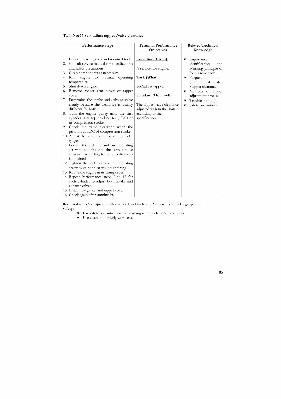
85
Task No: 17 Set/ adjust tappet /valve clearance.
Performance steps Terminal Performance Objectives
Related Technical Knowledge
1. Collect correct gasket and required tools. 2. Consult service manual for specifications
and safety precautions. 3. Clean components as necessary. 4. Run engine to normal operating
temperature. 5. Shut down engine. 6. Remove rocker arm cover or tappet
cover. 7. Determine the intake and exhaust valve
clearly because the clearance is usually different for both.
8. Turn the engine pulley until the first cylinder is at top dead center (TDC) of its compression stroke.
9. Check the valve clearance when the piston is at TDC of compression stroke.
10. Adjust the valve clearance with a feeler gauge.
11. Loosen the lock nut and turn adjusting screw to and fro until the correct valve clearance according to the specifications is obtained.
12. Tighten the lock nut and the adjusting screw must not turn while tightening..
13. Rotate the engine in its firing order. 14. Repeat Performance steps 7 to 12 for
each cylinder to adjust both intake and exhaust valves.
15. Install new gasket and tappet cover. 16. Check again after running in.
Condition (Given): A serviceable engine. Task (What): Set/adjust tappet. Standard (How well): The tappet/valve clearance adjusted with in the limit according to the specification.
� Importance,
identification and Working principle of four-stroke cycle
� Purpose and function of valve /tappet clearance
� Methods of tappet adjustment process
� Trouble shooting � Safety precautions
Required tools/equipment: Mechanics' hand tools set, Pulley wrench, feeler gauge etc. Safety:
� Use safety precautions when working with mechanic's hand tools. � Use clean and orderly work area.

86
Task No: 18 Service/ repair spark plug.
Performance steps Terminal Performance Objectives
Related Technical Knowledge
Removal 1. Disconnect negative terminal of battery 2. Remove high tension cord 3. remove spark plug 4. Check electrode wear 5. Check and clean carbon deposits 6. Check insulator damage 7. Change spark plug if found faulty Installation 1. Reverse the process of removal
Condition (Given): A serviceable vehicle in a workshop. Task (What): Service/ repair spark plug Standard (How well): Specified spark plug gap need to be maintained
� Working principle
of spark plug. � Selection of spark
plug � Safety precautions. � Interpretation of
service manual � Trouble shooting � Safety precautions
Required tools/equipment: Mechanic's hand tools set, Manufacturer's service manual, sand blaster etc. Safety:
� Use care when removing and replacing spark plug to avoid bodily injury. � Use care when working with mechanic's tools to avoid injury. � Maintain clean and orderly work area.

87
Task No: 19 Tune engine and test emission
Performance steps Terminal Performance Objectives
Related Technical Knowledge
1. Inspect/ top up/ change engine coolant 2. (refer auto service mechanic task 7) 3. Inspect/ top up/ change engine oil 4. (refer auto service mechanic task 6) 5. Inspect/ charge battery 6. (refer auto service mechanic task 16) 7. Inspect/ clean/ change air filter 8. (refer auto service mechanic task 8) 9. Inspect/ tighten alternator drive belt 10. (refer auto service mechanic task 17) 11. Inspect/ change glow plugs 12. Inspect/ set pressure in injection nozzle 13. (refer auto service mechanic task 20) 14. Adjust valve clearance 15. (refer auto service mechanic task 19) 16. Adjust injection timing (rotary pump) 17. Adjustment of idle speed and maximum
speed 18. Test emission using smoke tester
Condition (Given): A serviceable engine. Task (What): Tune engine and test emission Standard (How well): Engine speed to be set at optimum providing optimum condition Inspection to be carried out as per the manufacturer’s specification
� Engine mechanical � Fuel system � Cooling system � Pollution test
standard � Trouble shooting � Safety precautions
Required tools/equipment: Mechanics' hand tools set, Pulley wrench, feeler gauge, battery charger, belt tensioner, multimeter, injector testing bench, manufactures manual, nozzle cleaning kit, plunger stroke measuring tool, dial gauge, smoke tester etc. Safety:
� Use safety precautions when working with mechanic's hand tools. � Use clean and orderly work area. � Use safety precaution while cranking engine � Use mask while cleaning air filter � Use special tool for tightening alternator drive belt

88
Task No: 20 Inspect / change glow plug.
Performance steps Terminal Performance Objectives
Related Technical Knowledge
1. Remove bolts and glow plug connector 2. Check the continuity of glow plug 3. Inspect glow plug relay continuity 4. Inspect relay operation 5. Inspect glow plug resistor 6. Install glow plug 7. Heat and crank the engine
Condition (Given): A serviceable engine. Task (What): Inspect / change glow plug. Standard (How well): Voltage should not be applied more that 11 volts to glow plug glow plug should not be cleaned with oil or gasoline
� Principle of working
of glow plug � Principle of relay and
its function � Principle of resistor
and its function � Trouble shooting � Safety precautions
Required tools/equipment: Mechanics' hand tools set, multimeter, manufactures manual etc. Safety:
� Use safety precautions when working with mechanic's hand tools. � Use clean and orderly work area. � Use safety precaution while cranking engine

89
Task No: 21 Perform emission testing using smoke analyzer.
Performance steps Terminal Performance Objectives
Related Technical Knowledge
1. Disconnect any devices on the vehicle that
can reduce the pollutant in the exhaust gas by mixing them with air
2. Connect the smoke meter’s sampling holes to the vehicle exhaust pipe
3. Before taking the measurements accelerate fully six times and as quickly as possible, and bring the engine to maximum power each time, if six is a governer, then to the maximum allowed.
4. Take the measurements during further complete accelerations immediately following the first six.
5. Press the “MODE” key and select L!. 6. Press the “ZERO” key and wait for the
instrument to clear 7. Press the “COUNT ADV” key (the N
degree TEST display will read 1). When engine is at minimum number of RPMs accelerate quickly but gently until the injection delivery is at maximum. Maintain this position until the engine reaches its maximum number of RPMs. Then release the accelerator until the engine returns to the minimum number of RPMs.
8. Press the COUNT ADV key the N degree TEST display will read 2). Accelerate as described as point 8 above. The maximum allowed number of acceleration is ten. After the tenth acceleration without the four last valid readings the test is discontinued.
9. Repeat point number 7 and 8 till 4 equal reading.
Condition (Given): A good condition diesel vehicle. Task (What): Perform emission testing using smoke analyzer Standard (How well): 4 equal reading established
� National emission
norms � Principle of smoke
analyzer � Trouble shooting � Safety precautions
Required tools/equipment: Mechanics' hand tools set, Smoke analyzer. Safety:
� Use safety precautions when working with mechanic's hand tools. � Use clean and orderly work area. � Use mask while checking emission

90
Task No: 22 Adjust injection timing (rotary pump).
Performance steps Terminal Performance Objectives
Related Technical Knowledge
1. Install plunger stroke measurement tool
with dial gauge indicator 2. Set no 1 or no 4 cylinder to 25 degree or
more BTDC/ Compression 3. Adjust injection timing by setting dial
gauge at 0 mm 4. Recheck the dial to see that the dial
indicator remains at 0 while slightly rotating the crankshaft pulley clockwise or counter clockwise
5. Slowly rotate the crankshaft pulley clockwise until pulley groove is aligned with the timing pointer
6. Measure the plunger stroke as per the specification
7. Loosen union nuts of all injection pipes at injection pump side
8. Adjust plunger stroke by slightly tilting the injection pump body.
9. Tighten nuts holding injection pump to timing belt case
10. Remove tools with dial indicator 11. Start engine and check for leaks
Condition (Given): A serviceable vehicle with rotary pump. Task (What): Adjust injection timing aligning groove in timing pulley. Standard (How well): Plunger stroke to be measured as per the manufacture’s specification
� Principle of rotary
fuel injection pump � Setting injection
timing � Interpretation of
service manual � Trouble shooting � Safety precautions
Required tools/equipment: Mechanics' hand tools set, Pulley wrench, manufactures manual, plunger stroke measuring tool, dial gauge etc. Safety:
� Use safety precautions when working with mechanic's hand tools. � Use clean and orderly work area.

91
Task No: 23 Adjust idle speed and maximum speed.
Performance steps Terminal Performance Objectives
Related Technical Knowledge
1. Tune up engine 2. Let engine run till normal operational
temperature 3. Connect tachometer Adjust idle speed 1. Check that the adjusting lever touches the
idle speed adjusting screw when the accelerator pedal is released
2. if not adjust the accelerator linkage 3. Start engine 4. Check the idle speed 5. Adjust idle speed Adjust maximum speed 1. Check that the adjusting lever touches the
idle speed adjusting screw when the accelerator pedal is released
2. if not adjust the accelerator linkage 3. start the engine 4. Depressed the accelerator pedal all the way 5. Check the maximum speed 6. adjust the maximum speed
Condition (Given): A serviceable engine. Task (What): Set engine speed. Standard (How well): Engine speed has to be within specification when all accessories are switched off
� Principle of
tachometer � Difference between
Idle speed and maximum engine speed
� Trouble shooting � Safety precautions
Required tools/equipment: Mechanics' hand tools set, Pulley wrench, feeler gauge, battery charger, belt tensioner, multimeter, injector testing bench, manufactures manual, nozzle cleaning kit, plunger stroke measuring tool, dial gauge etc. Safety:
� Use safety precautions when working with mechanic's hand tools. � Use clean and orderly work area. � Use safety precaution while cranking engine � Use mask while cleaning air filter � Use special tool for tightening alternator drive belt

92
Task No: 24 Check compression pressure.
Performance steps Terminal Performance Objectives
Related Technical Knowledge
1. Warm up engine 2. Stop engine after warm up 3. Remove all spark plugs and disconnect high
tension cord from ignition coil. Disconnect CAS coupler (Injection model)
4. Install compression gauge (special tool) into spark plug hole.
5. Disengage clutch (to lighten starting load on engine), and depress accelerator pedal all the way to make throttle full open.
6. Crank engine with fully changed battery, read the highest pressure on compressor gauge.
7. Carry out Performance steps 4, 5 and 6 for all cylinders.
Condition (Given): A serviceable engine. Task (What): Check gas leak from cylinder. Standard (How well): Compression pressure has to be within the specified limit.
� Operation of
engine � Function of
compressor and oil ring
� Terms related to engine compression
� Trouble shooting � Safety precautions .
Required tools/equipment: Mechanics' hand tools set, compression gauge Safety:
� Use safety precautions while cranking engine � Use safety precautions when working with mechanic's hand tools. � Maintain clean and orderly work area.

93
Task No: 25 Diagnose engine problem.
Performance steps Terminal Performance Objectives
Related Technical Knowledge
Hard Starting Ignition system out of order 1. Check and change fuse 2. Check, clean and adjust spark plug 3. Check/replace leakage in high tension cord 4. Check and adjust ignition timing 5. Check and adjust ignition coil 6. Check and change rotor and cap of
distributor 7. Check and change igniter 8. Check noise suppressor 9. Check ECM 10. Check IC system 11. Check adjust signal rotor air gap 12. Check and adjust generator assy in
distributor Fuel system out of order 1. Check fuel in fuel tank 2. Check and change fuel filter 3. Check clean fuel hose 4. Check change fuel pump 5. Check air inhaling from intake system 6. Check repair carburetor choke 7. Check carburetor 8. Check fuel cut solenoid valve Low compression 1. Check spark plug tightening and gasket 2. Check adjust valve lash 3. Check compression leak from valve seal 4. Check sticky valve stem 5. Check for weak of damage valve spring 6. Check compression leak in cylinder head
gasket 7. Check for damaged piston rings 8. Check piston, ring and cylinder Others 1. Check timing belt 2. Check functioning of PCV valve 3. Check vacuum hose Improper engine idling Fuel system out of order 1. Check and adjust idle adjustment 2. Check fuel in fuel tank 3. Check air cleaner element 4. Check manifold throttle body and cylinder
head gasket for leakage
Condition (Given): A serviceable vehicle. Task (What): Diagnose faulty engine. Standard (How well): The Performance steps has to be followed in sequence for finding fault and repair
� Engine mechanical � Ignition system � Fuel system � Cooling system � Engine electronics � Emission control
devices � Trouble shooting � Safety precautions

94
5. Check carburetor jet 6. Check float level in carburetor 7. Check choke system 8. Check fuel cut solenoid valve Ignition system out of order 1. Refer ignition system above Low compression 1. Refer low compression above Others 1. Check low connection or disconnection of
vacuum hoses 2. Check malfunctioning EGR valve 3. Check malfunctioning PCV valve Engine hesitates Ignition system out of order 1. Refer ignition system above Fuel system out of order 1. Refer fuel system above Others 1. Check malfunctioning EGR valve Required tools/equipment: Mechanics' hand tools set Safety:
� Be sure that the hoses and electrical connectors are marked clearly before dismantling. � Use safety practice when removing manifolds and working with engine to avoid injury. � Use safety precautions when working with mechanic's hand tools. � Maintain clean and orderly work area.

95
Module:1 Sub Module 2
Cooling and lubrication System Description: This sub module intends to provide knowledge and skills about auto cooling and lubricating system. Objectives: After completion of this module the trainees will be able to: 1. Be familiar with cooling system 2. Maintain cooling system Duration: 15 hours (3 hours theory and 12 hours practical) Competencies 1. Change thermostat. 2. Seal leakage in cooling system. 3. Repair/replace water pump. 4. Repair/replace radiator. 5. Replace oil cooler. 6. Replace oil pump.

96
Task No: 1 Change thermostat.
Performance steps Terminal Performance Objectives
Related Technical Knowledge
1. Drain cooling system.
2. Remove thermostat housing and thermostat.
3. Clean gasket surfaces.
4. Check thermostat for operation. 5. Install thermostat and housing using
new gasket. 6. Refill cooling system to proper level
with coolant.
7. Test pressure system for leaks. 8. Operate engine until it reaches normal
operating temperature.
9. Recheck coolant level.
Condition (Given): A vehicle in a workshop. Task (What): Replace Thermostat. Standard (How well): The thermostat valve changed and the engine must perform at manufacturer's recommended
temperature + or - 10° F.
� Interpretation of
service manuals � Importance,
functions and types of cooling system
� Principle of temp control sensor
� Technical terms associated with cooling system
� Operating principles, function and types of thermostat
� Methods of testing thermostat
� Troubleshooting
Required tools/equipment: Mechanic's hand tools set, Manufacturer's service manual, Temperature tester (thermometer), Heater, container, jar etc. Safety:
� Use care when removing/testing or working with thermostat to avoid injury. � Use care when working with mechanic's hand tools. � Maintain clean and orderly work area.

97
Task No: 2 Seal leakage in cooling system.
Performance steps Terminal Performance Objectives
Related Technical Knowledge
1. Determine the location/ points of leaks.
2. Drain cooling system. Seal radiator leakage:
1. Remove radiator following recommended procedures.
2. Locate leaks by pressure testing.
3. Clean and solder area needing repair. 4. Check repairs by pressure testing.
5. Reinstall radiator.
6. Refill cooling system to proper level. Seal core-hole plugs (freeze plugs):
1. Remove old plugs.
2. Clean plug seat and coat with sealing compound on outer edges.
3. Drive new plugs into place with proper tool.
Seal gasket leakages:
1. Remove old gasket. 2. Clean gasket mating surfaces.
3. Install new gasket.
4. Use sealing compound if necessary. 5. Retorque attaching bolts. Seals stud bolts and cap screws:
1. Remove bolts and screws.
2. Clean threads. 3. Apply sealing compounds to threads. 4. Reinstall and torque bolts and screws. 5. Complete the work order.
6. Refill cooling system to proper level with coolant.
7. Test pressure system for leaks.
8. Operate engine until it reaches normal operating temperature.
9. Recheck coolant level.
Condition (Given): A leaking cooling system of a vehicle. Task (What): Seal radiator leakage Seal core-hole plugs (freeze plugs) Seal gasket leakages Seal stud bolts and cap screws Standard (How well): Radiator leakage sealed Core-hole plugs (freeze plugs) sealed. Gasket leakages sealed Stud bolts and cap screws sealed.
� Interpretation of
service manuals � Importance,
functions, types and parts cooling system.
� Technical terms associated with cooling system.
� Methods of testing pressure and temperature
� Causes and effects of leaks
� Troubleshooting � Safety precautions
Required tools/equipment: Mechanic's hand tools set, Manufacturer's service manual, soldering kit, pressure and temperature tester, container, jar etc. Safety:
� Use care when working with mechanic's hand tools. � Use care when removing and soldering radiator to avoid injury. � Maintain clean and orderly work area.

98
Task No: 3 Repair/replace water pump.
Performance steps Terminal Performance Objectives
Related Technical Knowledge
1. Consult service manual noting safety procedures.
2. Drain cooling system.
3. Disconnect lower radiator hose and pump.
4. Remove fan pulley and fan hub. 5. Remove pump by pass hose if equipped.
6. Remove water pump.
7. Clean block surface of all old gaskets. 8. Disassemble pump according to
manufacturer's recommended procedures.
9. Clean all parts and gasket mating surfaces. 10. Check water pump kit, impeller, shaft and
bearings for wear. 11. Reassemble pump using new parts
according to manufacturer's recommended procedures and specifications.
12. Install water pump using new gasket. 13. Refill cooling system to proper level with
coolant. 14. Test pressure system for leaks.
15. Operate engine until it reaches normal operating temperature.
16. Recheck coolant level.
Condition (Given): A vehicle in a workshop. Task (What): Replace water pump. Standard (How well): The defective parts or parts of water pump replaced. The pump must perform according to service manual or manufacturer's specifications.
� Interpretation of
service manuals. � Importance, types
and parts of water pump
� Working principles and functions of water pump
� Technical terms associated water pump
� Water pump repairing process
� Troubleshooting. � Safety precautions
Required tools/equipment: Mechanic's hand tools set, Manufacturer's service manual, pressure and temperature tester, container, jar etc. Safety:
� Use care when working with mechanic's hand tools. � Use care when removing and repairing water pump to avoid injury. � Maintain clean and orderly work area.

99
Task No: 4 Repair/replace radiator.
Performance steps Terminal Performance Objectives
Related Technical Knowledge
1. Consult service manual noting safety procedures.
2. Drain coolant from engine.
3. Remove upper and lower radiator hoses.
4. Remove mounting bolts. 5. Remove radiator.
6. Locate leaks by pressure testing.
7. Clean and solder area needing repair. 8. Check radiator by pressure testing.
9. Install radiator by replace mounting bolts.
10. Replace upper and lower radiator hoses. 11. Refill radiator with coolant. 12. Test pressure system for leaks. 13. Operate engine until it reaches normal
operating temperature. 14. Recheck coolant level.
Condition (Given): A vehicle in a workshop. Task (What): Replace radiator. Standard (How well): The old radiators removed and replaced with new or rebuild one. Radiator must not leak upon completion of installation.
� Interpretation of
service manuals � Importance,
function, types and parts of radiator.
� Working principles and functions of radiator
� Technical terms associated with radiator
� Radiator repairing/testing process
� Troubleshooting. � Safety precautions
Required tools/equipment: Mechanic's hand tools set, Manufacturer's service manual, pressure and temperature tester, container, jar etc. Safety:
� Use care when removing and repairing radiator to avoid injury. � Don't open the radiator cap when engine is hot. � Use care when working with mechanic's hand tools. � Maintain clean and orderly work area.

100
Task No: 5 Replace oil cooler.
Performance steps Terminal Performance Objectives
Related Technical Knowledge
1. Consult service manual noting safety procedures.
2. Clean external surface of cooler and surrounding engine area.
3. Drain cooler if possible.
4. Disconnect lube oil inlet and outlet lines and cap ends of lines.
5. Remove cooler.
6. Install new cooler.
7. Reconnect oil lines using new gaskets or seals.
8. Add oil to crankcase if necessary.
9. Operate engine and check for oil leaks. 10. Stop engine and check oil level and
correct as necessary.
Condition (Given): A vehicle in a workshop. Task (What): Replace oil cooler. Standard (How well): Oil cooler replaced.
� Interpretation of
service manuals � Importance,
advantages, functions of oil cooler
� Operating principles, types and parts of oil cooler
� Technical terms associated with oil cooler
� Process of repairing/testing cooler
� Troubleshooting � Safety precautions
Required tools/equipment: Mechanic's hand tools set, Manufacturer's service manual, pressure and temperature tester, container, jar etc. Safety:
� Use care when working with mechanic's hand tools. � Use care when removing and repairing oil cooler to avoid injury. � Maintain clean and orderly work area.

101
Task No: 6 Replace oil pump.
Performance steps Terminal Performance Objectives
Related Technical Knowledge
1. Locate the oil pump in the engine.
2. Remove all parts to gain access to remove oil pump.
3. Remove oil pump assembly.
4. Remove oil filter. 5. Clean oil strainer. 6. Disassemble the oil pump according to
manufacturer's procedures. 7. Inspect the worn parts to be replaced. 8. Examine to determine reason for failure
before replacing with new pump. 9. Get replaced parts or new pump.
10. Reassemble the oil pump as per service manual's procedures and specifications.
11. Install the oil strainer and oil pump to the engine.
12. Connect the oil supply pipes. 13. Replace all the parts that were removed to
gain access to the oil pump.
Condition (Given): A vehicle in a workshop. Task (What): Replace oil pump. Standard (How well): Oil pump replaced.
� Interpretation of
service manuals � Importance,
functions and parts of oil pump.
� Working principle, functions and types of oil pump
� Principle of oil pressure sensors
� Technical terms associated with oil pump
� Methods of repairing/testing oil pump
� Trouble shooting
Required tools/equipment: Mechanic's hand tools set, Manufacturer's service manual, pressure and temperature tester, circlip pliers, container, jar etc. Safety:
� Use care when working with mechanic's hand tools. � Use care when removing and repairing oil pump to avoid injury. � Maintain clean and orderly work area.

102
Module: 1 Sub Module 3
Fuel System with MPFI Description: This sub module intends to provide knowledge and skills about auto fuel system including MPFI Objectives: After completion of this module the trainees will be able to: 1. Be familiar with fuel system including MPFI 2. Maintain fuel system with MPFI Duration: 30 hours (6 hours theory and 24 hours practical) Tasks:
1. Replace injector nozzle. 2. Set injector pressure. 3. Remove/replace fuel tank. 4. Remove/replace EGR valve. 5. Remove/replace Catalytic Converter. 6. Remove/replace fuel feed pump. 7. Overhaul carburetor. 8. Set diesel fuel injection pump timing. 9. Bleed fuel system. 10. Replace fuel level sending unit. 11. Read memory switch mode (Blink code method) 12. Trouble shoot using MPFI diagnostic tester.

103
Task No: 1 Replace injector nozzle.
Performance steps Terminal Performance Objectives
Related Technical Knowledge
1. Locate and gain access to the injector(s).
2. Clean the area around the fuel injector(s).
3. Pull or plug the fuel or oil leakage lines as required per manufacturer's procedure.
4. Remove any electrical connections if used.
5. Remove the fuel line at the injector nozzle at the injection pump using the special equipment as required by manufacturer.
6. Cap the fuel lines and injection pump openings.
7. Loosen the fuel line clamp and remove the fuel line as per manufacturer's procedure.
8. Remove the injector(s) as per manufacturer's procedure and specifications and mark the injector for replacement.
9. Plug the cylinder block injector nozzle opening if more injectors are removed.
10. Clean the injector nozzle opening in the cylinder block.
11. Install new heat shield into the injector nozzle openings if required.
12. Apply a copper-based, anti-seize compound to the nozzle threads.
13. Remove the protective plug from the cylinder block.
14. Install injector nozzle(s) into the original positions as per manufacturer's specifications.
15. Remove the protective caps from the fuel lines, injector pump and injector nozzles.
16. Install fuel lines, nozzle/fuel line clamps.
17. Reattach electrical connections.
18. Reconnect the fuel or oil leakage lines.
19. Bleed the fuel system.
20. Reinstall any parts removed to gain access to the nozzle.
21. Start the engine, check for leakage and correct as necessary.
Condition (Given): A serviceable fuel injection pump of a diesel engine. Task (What): Replace injectors. Standard (How well): The injectors seated, tightened and nozzle performed according to manufacturer's specifications for fuel pattern and pressure.
� Interpretation of
service manuals � Identification, types
and uses of electrical connectors
� Importance, purpose and applications of fuel injection pumps.
� Working principles, functions and types of the fuel injection pump
� FI pump removing and replacing process
� Identification, types and parts of fuel injection pumps
� Trouble shooting � Safety precautions
Safety: � Ventilate exhaust gases to protect respiratory system. � Follow correct safety practices around flammable liquids. � Follow correct safety practices when working with pressurized fuel systems. � Use care when working with mechanic's tools to avoid injury. � Maintain clean and orderly work area.
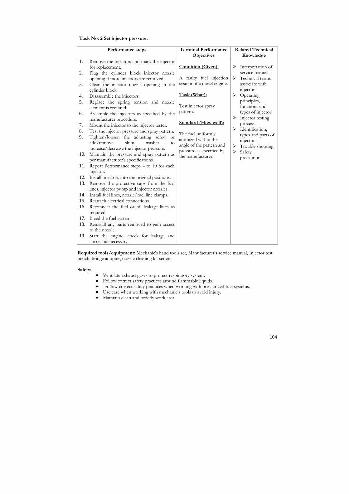
104
Task No: 2 Set injector pressure.
Performance steps Terminal Performance Objectives
Related Technical Knowledge
1. Remove the injectors and mark the injector for replacement.
2. Plug the cylinder block injector nozzle opening if more injectors are removed.
3. Clean the injector nozzle opening in the cylinder block.
4. Disassemble the injectors.
5. Replace the spring tension and nozzle element is required.
6. Assemble the injectors as specified by the manufacturer procedure.
7. Mount the injector to the injector tester.
8. Test the injector pressure and spray pattern.
9. Tighten/loosen the adjusting screw or add/remove shim washer to increase/decrease the injector pressure.
10. Maintain the pressure and spray pattern as per manufacturer's specifications.
11. Repeat Performance steps 4 to 10 for each injector.
12. Install injectors into the original positions. 13. Remove the protective caps from the fuel
lines, injector pump and injector nozzles.
14. Install fuel lines, nozzle/fuel line clamps. 15. Reattach electrical connections.
16. Reconnect the fuel or oil leakage lines as required.
17. Bleed the fuel system.
18. Reinstall any parts removed to gain access to the nozzle.
19. Start the engine, check for leakage and correct as necessary.
Condition (Given): A faulty fuel injection system of a diesel engine. Task (What): Test injector spray pattern. Standard (How well): The fuel uniformly atomized within the angle of the pattern and pressure as specified by the manufacturer.
� Interpretation of
service manuals � Technical terms
associate with injector
� Operating principles, functions and types of injector
� Injector testing process.
� Identification, types and parts of injector
� Trouble shooting. � Safety
precautions.
Required tools/equipment: Mechanic's hand tools set, Manufacturer's service manual, Injector test bench, bridge adopter, nozzle cleaning kit set etc. Safety:
� Ventilate exhaust gases to protect respiratory system. � Follow correct safety practices around flammable liquids. � Follow correct safety practices when working with pressurized fuel systems. � Use care when working with mechanic's tools to avoid injury. � Maintain clean and orderly work area.

105
Task No: 3 Remove/replace fuel tank.
Performance steps Terminal Performance Objectives
Related Technical Knowledge
1. Disconnect the negative battery terminal.
2. Bleed the fuel system as necessary per manufacturer's procedure.
3. Remove the fuel from the fuel tank.
4. Raise the back of the vehicle and safety support on jack stands or hoist.
5. Disconnect fuel lines and electrical connections.
6. Disconnect fuel filler tube.
7. Support the fuel tank. 8. Remove the fuel tank attachment
hardware and tank.
9. Remove and clean components from old fuel tank.
10. Clean the components with correct sealant on the new fuel tank per manufacturer's procedure.
11. Install fuel tank and attachment hardware.
12. Reconnect fuel lines and electrical connections.
13. Reconnect fuel filler tube.
14. Fill fuel tank and check for leaks.
15. Pressurize the fuel system and check for leaks per manufacturer's procedures.
16. Lower the vehicle off the jack stands or hoist.
17. Reconnect the negative battery terminal.
Condition (Given): A vehicle in a workshop. Task (What): Remove/replace fuel tank. Standard (How well): The fuel tank and components installed securely in original position with no leaks.
� Interpretation
service manuals. � Technical terms
associate with fuel tank
� Identification, and parts of fuel tank
� Working principles, functions and types of fuel tank.
� Fuel tank removing, cleaning and replacing tank process
� Trouble shooting � Safety precautions
Required tools/equipment: Mechanic's hand tools set, Manufacturer's service manual, fuel storage container, jack stands, hoist, etc. Safety:
� Observe all safety rules when lifting or working under vehicle. � Ventilate exhaust gases to protect respiratory system. � Follow correct safety practices around flammable liquids. � Follow correct safety practices when working with pressurized fuel systems. � Use care when working with mechanic's tools to avoid injury. � Maintain clean and orderly work area.

106
Task No: 4 Remove/replace EGR valve.
Performance steps Terminal Performance Objectives
Related Technical Knowledge
1. Locate Exhaust Gas Recirculation (EGR) valve.
2. Remove components to gain access to valve.
3. Disconnect vacuum hose from EGR valve.
4. Remove valve-mounting hardware. 5. Clean valve mounting surface.
6. Install replacement gasket and valve as per manufacturer's procedure and specifications.
7. Reattach vacuum hose to valve. 8. Check EGR valve operation as per
manufacturer's procedure and specifications.
9. Reinstall the components removed to gain access.
Condition (Given): A vehicle in a workshop. Task (What): Remove/replace EGR valve. Standard (How well): When external vacuum applied to EGR valve at idle speed, engine stalled or idle roughly indicating exhaust gas is Recirculation: idle improved when vacuum is removed as per manufacturer's procedure and specifications.
� Interpretation of
service manuals � Importance and issues
of vehicles pollution. � Technical terms
associated with emission control system
� Purpose, operation and types of the EGR valve
� Technical terms associate with EGR valve
� Identification and parts of EGR valves.
� Operating principles and functions of EGR valves
� Emission standards and government rules
Required tools/equipment: Mechanic's hand tools set, Manufacturer's service manual, vacuum pump, vacuum gauge and tee fittings etc. Safety:
� Ventilate exhaust gases to protect respiratory system. � Follow correct safety practices around flammable liquids. � Follow correct safety practices when working with pressurized fuel systems. � Use care when working with mechanic's tools to avoid injury. � Maintain clean and orderly work area

107
Task No: 5 Remove/replace Catalytic Converter.
Performance steps Terminal Performance Objectives
Related Technical Knowledge
1. Raise the vehicle and support on jack stands or hoist.
2. Remove attaching clamps or bolts, which fasten converter to the exhaust system.
3. Remove the lower heat shield if required.
4. Loosen exhaust system silencer pipe hangers behind the converter if required.
5. Remove the catalytic converter. 6. Clean the exhaust pipes and converter
attaching hardware.
7. Install replacement catalytic converter. 8. Realign and secure the clamps, bolts,
and hangers on the exhaust system behind the catalytic converter.
9. Secure the catalytic converter attaching hardware.
10. Reattach the catalytic converter lower heat shield as required.
11. Recheck the exhaust system alignment.
12. Lower the vehicle and remove the jack stands and hoist.
Condition (Given): A vehicle in a workshop. Task (What): Remove/replace Catalytic Converter. Standard (How well): The catalytic converter installed according to the manufacturer's procedure without leaks or misalignment.
� Interpretation
service manuals � Importance and
purpose of emission / Pollution control and pollutant gases.
� Present scenario of vehicle emission
� Purpose and operation of catalytic converter
� Technical terms associate with emission control.
� Identification, types and parts of emission control devices
� Operating principles and functions of catalytic converter.
� Emission gases testing process
� Gas analyzer
Required tools/equipment: Mechanic's hand tools set, Manufacturer's service manual, vacuum pump, vacuum gauge and tee fittings etc. Safety:
� Use correct safety procedures when raising and lowering or working under vehicles. � Ventilate exhaust gases to protect respiratory system. � Follow correct safety practices around flammable liquids. � Follow correct safety practices when working with pressurized fuel systems. � Use care when working with mechanic's tools to avoid injury. � Maintain clean and orderly work area.

108
Task No: 6 Remove/replace fuel feed pump.
Performance steps Terminal Performance Objectives
Related Technical Knowledge
1. Determine the type of fuel feed pump to be replaced.
To remove/replace a mechanical type fuel pump follow these Performance steps.
1. Remove the air cleaner assembly as required.
2. Render the ignition system inoperative per manufacturer's procedure.
3. Locate and gain access to fuel pump.
4. Disconnect and plug fuel lines. 5. Remove fuel pump fastening hardware
and remove pump.
6. Clean fuel pumps mounting area of old gasket material and foreign matter.
7. Install replacement fuel pump and mounting hardware.
8. Reconnect fuel lines.
9. Reinstall any components that were removed to gain access to the fuel pump.
10. Start engine and check for leaks. To remove/replace an electrical type fuel pump and the engine is not fuel injected follow these Performance steps.
1. Disconnect battery. 2. Locate and gain access to fuel pump.
3. Disconnect and plug fuel lines.
4. Disconnect electrical connections. 5. Remove fuel-mounting hardware.
6. Remove fuel pump.
7. Clean fuel pump mounting area of corrosion or foreign material.
8. Install replacement fuel pump including any necessary installation kit per manufacturer's specifications.
9. Reconnect fuel lines.
10. Reattach electrical connections.
11. Reconnect battery. 12. Reinstall components that were
removed to gain access to the fuel pump.
13. Run pump and check operation. To remove/replace an electrical external type fuel pump and the engine is not
Condition (Given): A serviceable vehicle. Task (What): Replace/remove fuel pump. Standard (How well): Mechanical or electrical fuel pump replaced to manufacturer's specifications and procedure with no fuel leaks.
� Interpretation of
service manuals � Importance, purpose
and types of fuel pumps
� Identification, selection and set up fuel pump
� Interpret the results of fuel pump tests.
� Identification, types and uses of hose/electrical connectors and clamps
� Purpose and function of mechanical and electrical fuel pumps.
� Technical terms associated with fuel pumps
� Types and parts of fuel pumps
� Working principles and functions of fuel pumps
� Fuel pump removing, replacing and testing process
� Trouble shooting. � Safety precautions

109
injected Follow these Performance steps.
1. Disconnect battery. 2. Locate and gain access to fuel pump.
3. Depressurize the fuel system per manufacturer's procedures.
4. Disconnect and plug fuel lines.
5. Disconnect electrical connections.
6. Remove fuel pump mounting hardware.
7. Remove fuel pump. 8. Clean fuel pump mounting area of
corrosion or foreign material.
9. Install replacement fuel pump including any necessary installation kit per manufacturers specifications.
10. Reconnect fuel lines.
11. Reconnect battery.
12. Pressurize the fuel system and check fittings for leaks.
13. Reinstall components that were removed to gain access to the fuel pump.
To remove/replace an electrical in-tank type fuel pump and the engine is not fuel injected Follow these Performance steps.
1. Disconnect the negative battery terminal.
2. Depressurize the fuel system.
3. Drain as much fuel out of the fuel tank by pumping out through the filler neck.
4. Raise the back of the vehicle and support on jack stands.
5. Disconnect the fuel supply, return and vent lines from the frame of the vehicle.
6. Disconnect the wiring harness from the fuel pump.
7. Support the fuel tank, loosen and remove the mounting straps.
8. Remove the fuel tank.
9. Disconnect the fuel lines and wiring harness from the pump flange.
10. Clean the outside of the mounting flange and retaining ring.
11. Remove the fuel pump lock ring per manufacturer's procedures.
12. Remove the fuel pump.
13. Clean the pump mounting surfaces.
14. Install the sealant, new fuel pump and lock ring.
15. Reconnect the fuel lines and wiring

110
harness to the pump flange.
16. Install the fuel tank. 17. Support the fuel tank, replace and
tighten the mounting straps.
18. Reconnect the wiring harness to the fuel pump.
19. Reconnect the fuel supply, return and vent lines to the vehicle frame.
20. Lower the vehicle off the jack stands.
21. Reconnect the negative battery terminal.
22. Pressurize the fuel system and check fittings for leaks.
23. Start the engine and check for leaks. Required tools/equipment: Mechanic's hand tools set, Manufacturer's service manual, special testing equipment as required, jack stands, pressure gauge, etc. Safety:
� Observe all safety rules when lifting or working under vehicles. � Ventilate exhaust gases to protect respiratory system. � Follow correct safety practices around flammable liquids. � Follow correct safety practices when working with pressurized fuel systems. � Use care when working with mechanic's tools to avoid injury. � Maintain clean and orderly work area.

111
Task No: 7 Overhaul Carburetor.
Performance steps Terminal Performance Objectives
Related Technical Knowledge
1. Disconnect the negative battery terminal.
2. Remove the air cleaner.
3. Remove filler cap from the fuel tank.
4. Place a container under the fuel inlet line and disconnect the fuel line.
5. Disconnect the vacuum hoses and electrical connectors after marking them with tape for identification when reinstalling.
6. Disconnect the throttle linkage.
7. Remove any brackets or carburetor mountings as required.
8. Lift carburetor from intake manifold being careful not to spill the fuel.
9. Disassemble carburetor per manufacturer's specifications.
10. Soak carburetor in clean solvent to remove foreign materials.
11. Rinse carburetor in hot water and blow-dry all passages with shop air.
12. Reassemble carburetor using new components from overhaul kit as required.
13. Make all adjustments during reassembly as per manufacturer' specifications.
14. Clean carburetor mounting area.
15. Install new gaskets.
16. Install carburetor. 17. Install and secure carburetor
mounting. 18. Reconnect throttle linkage to
carburetor.
19. Reconnect hoses and electrical connectors.
20. Reconnect the fuel line.
21. Replace the fuel cap on the fuel tank.
22. Reconnect the negative battery terminal.
23. Start the engine and warm it up to normal operating temperatures.
Condition (Given): A serviceable carburetor of a petrol engine. Task (What): Overhaul carburetor. Standard (How well): Carburetor cleaned, installed, secured and adjusted to manufacturer's specifications according to manufacturer's procedure with no fuel or vacuum leaks.
� Interpretation of
service manuals � Identification, types
and uses of electrical/hose connectors and clamps
� Technical terms associated with carburetors
� Importance, purpose, types of carburetors
� Working principles and functions of the carburetors
� Parts identification of carburetors
� Carburetor circuits � Carburetor tuning
process � Trouble shooting

112
24. Adjust the carburetor to manufacturer's specifications and procedures.
25. Reinstall air cleaner assembly. Safety:
� Observe all safety rules when lifting or working under vehicles. � Ventilate exhaust gases to protect respiratory system. � Wear safety goggles and use extreme care when using air to blow-dry the passages to
avoid injury to skin or eyes. � Follow correct safety procedures when using compressed air. � Follow correct safety practices around flammable liquids.

113
Task No: 8 Set diesel fuel injection pump timing.
Performance steps Terminal Performance Objectives
Related Technical Knowledge
1. Disconnect the negative battery terminal.
2. Remove components as necessary to gain access to the injection pump.
3. Remove the injection pump distributor head plug bolt and sealing washer or equivalent as per manufacturer's procedure and specifications.
4. Install static timing gauge with dial indicator, so that indicator pointer is in contact with the injection pump plunger as per manufacturer's procedure.
5. Remove the timing mark cover from transmission housing.
6. Align timing mark (TDC) with pointer on the rear engine cover plate.
7. Rotate the crankshaft pulley slowly, counterclockwise until the dial indicator stops moving as per manufacturer's procedure and specifications.
8. Turn the crankshaft clockwise until crankshaft-timing mark aligns with indicator pin.
9. Check the dial indicator reading as per manufacturer's specifications.
10. Loosen the pump mounting bolts and rotate the pump toward the engine to advance the timing and away from the engine to retard the timing until the reading is within the manufacturer's specifications.
11. Tighten the pump mounting bolts if the reading is within specifications.
12. Repeat Performance steps 6 to 11 to make sure that the timing is adjusted correctly.
13. Remove the dial indicator and adopter. 14. Install the injection pump distributor head
plug or equivalent as per manufacturer's procedure and specifications.
15. Connect the negative battery terminal.
16. Run the engine, check and adjust the idle RPM, if necessary.
17. Check for fuel leaks.
Condition (Given): A serviceable fuel injection pump of a diesel engine. Task (What): Time the fuel injection pump. Standard (How well): The fuel injection pump timed and performed in accordance with manufacturer's specifications.
� Interpretation of
service manuals. � Identification the
types and applications of fuel injection pumps.
� Working principles, functions and types of the fuel injection pump
� FI pump timing setting process.
� Interpretation the results of fuel injection test equipment
� Technical terms associated with fuel injection pumps
� Trouble shooting � Safety precautions
Safety: � Use care when working with mechanic's tools to avoid injury. � Maintain clean and orderly work area.

114
Task No: 9 Bleed fuel system.
Performance steps Terminal Performance Objectives
Related Technical Knowledge
1. Determine whether the fuel injection system is mechanical, electrical, petrol or diesel according to manufacturer's specifications.
2. Loosen fuel pump outlet line and crank engine until fuel flows from connection as per manufacturer's procedure.
3. Tighten connection and outlet.
4. Loosen connection at fuel filter outlet, and crank engine until fuel flows from connections.
5. Tighten connection at fuel filter outlet.
6. Loosen fuel line connections at fuel injectors and crank engine until fuel appears.
7. Retighten the connection. 8. Repeat this step for all the fuel injectors.
9. Start the engine and operate for period of time necessary to purge remaining air from lines as per manufacturer's procedure.
Condition (Given): A serviceable fuel injection pump of a diesel engine. Task (What): Bleed the fuel system in diesel engine. Standard (How well): The fuel systems bleed and performed in accordance with manufacturer's specifications.
� Interpretation of
service manuals. � Identification the
types of fuel system � Importance and
purpose and functions of bleeding fuel systems
� Technical terms associated with bleeding the fuel system.
� Trouble shooting
Required tools/equipment: Mechanic's hand tools set, Manufacturer's service manual, special equipment as required by manufacturer etc. Safety:
� Ventilate exhaust gases to protect respiratory system. � Follow correct safety practices around flammable liquids. � Follow correct safety practices when working with pressurized fuel systems. � Use care when working with mechanic's tools to avoid injury. � Maintain clean and orderly work area.

115
Task No: 10 Replace fuel level sending unit.
Performance steps Terminal Performance Objectives
Related Technical Knowledge
1. Disconnect the negative battery terminal.
2. Depressurize the system per manufacturer's procedures.
3. Locate fuel level sending unit.
4. Remove fuel tank if necessary to gain access to the sending unit.
5. Clean sending unit area to prevent dirt from entering the fuel tank.
6. Siphon fuel as necessary to lower the fuel level below the sending unit opening.
7. Remove the sending unit fuel lines, electrical connections and attachment hardware.
8. Remove the sending unit.
9. Clean the sending unit mounting surface. Do not get dirt into the fuel tank.
10. Install replacement sending unit, gaskets or seals per manufacturer's procedures.
11. Reattach fuel lines and electrical connections.
12. Pressurize the fuel system and check for leaks per manufacturer's procedures.
13. Reinstall any components that were removed to gain access to the fuel-sending unit.
14. Reconnect the negative battery terminal.
15. Check out put voltage and/or gauge while filling the tank.
Condition (Given): A serviceable vehicle. Task (What): Remove/replace fuel level sending unit. Standard (How well): The fuel level sending unit installed in position as specified by manufacturer with no leakage and output voltage set as specified for different fuel levels.
� Interpretation of
manufacturer's service manuals
� Identification, selection and set up fuel level sending unit and gauge
� Interpretation the results of fuel level sending unit tests
� Operating principles, functions and types of fuel level sending unit
� Technical terms associated with fuel level sending units
� Trouble shooting
Required tools/equipment: Mechanic's hand tools set, Manufacturer's service manual, fuel storage container, special equipment as required by manufacturer etc. Safety:
� Observe all safety rules while lifting or working under vehicle. � Ventilate exhaust gases to protect respiratory system. � Follow correct safety practices around flammable liquids. � Follow correct safety practices when working with pressurized fuel systems. � Use care when working with mechanic's tools to avoid injury. � Maintain clean and orderly work area.

116
Task No: 11 Read memory switch mode (Blink code method)
Performance steps Terminal Performance Objectives
Related Technical Knowledge
1. Locate memory switch mode connector. 2. Short the terminal of the connector as per
service manual's procedures and instructions.
3. Turn the Ignition switch ON. 4. Check engine lamp on dashboard start
blinking at every 0.5sec if there is no defect.
5. Read the lamp blinking frequency is co-related to a trouble code occurred in the vehicle. The blinking trouble code refers first digit with slow & second digit with fast blinking.
6. Refer the service manual of the respective vehicle manufacturer to locate the malfunction components as per service manual's procedures and specifications.
7. Remove the battery supply for at least minutes to erase the history code.
8. Diagnose the defects on sensors as per blinking code.
9. Refer the service manual to locate the defective parts/sensors.
10. Disconnect the sensors or component that were detected as per blinking code.
11. Test the following components or sensors for malfunction conformation.
• Water temperature sensor
• Air temperature sensor
• Manifold air pressure sensor
• Idle speed control valve
• Throttle position sensor
• Lambda sensor
• Vehicle speed sensor 12. Replace the defective components. 13. Connect the respective connector and
battery supply. 14. Determine the vehicle is in normal/safe
mode. 15. Follow the Performance steps as per
service manual's procedure to run the vehicle in normal mode if it is in safe mode.
16. Check the engine lamp on dashboard is not light.
Condition (Given): A MPFI equipped vehicle in a workshop. Task (What): Read memory switch mode method. Find blink code of the fault. Standard (How well): Diagnostic connector connected as per service manual's procedures. The blinking code detected. The defective parts detected, tested and replaced. The history code or safe mode is erased. Upon completion of the task the vehicle must be run in normal mode with out glowing engine lamp.
� Interpretation of
service manuals � Basic electricity and
electronics � Introduction,
importance, advantages and types of MPFI system.
� Technical terms associated MPFI system
� Working principles, functions and parts of MPFI system
� Importance, functions and types of Input, output sensors, actuators and control devices.
� OBD and diagnostic tester operating procedure
� Trouble shooting procedure
� Safety precautions

117
Safety: * Observe all safety rules while operating OBD tester and working with MPFI vehicle.
� Always ensure that electrical connections are correct and multimeter selector switch selected as specified parameter and range required.
� Read instructions before operating OBD/MPFI diagnostic tester.

118
Task No: 12 Trouble shoot using MPFI diagnostic tester.
Performance steps Terminal Performance Objectives
Related Technical Knowledge
1. Locate the memory switch mode connector. 2. Connect MPFI diagnostic tester as per
manufacturer's procedures and instructions. 3. Diagnose the following sensors if found
faulty.
• Battery Voltage
• Vehicle speed sensor
• Engine rpm sensor
• Coolant temperature sensor
• Ignition timing
• Throttle position sensor
• Fuel injection pulse
• ISC valve
• O2 sensor
• Intake air temperature sensor
• Crank angle sensor
4. Replace new sensors if found defective but they are not recommended to be repaired.
5. Apply multi-meter for checking wiring harness.
Condition (Given): A MPFI equipped vehicle in a
workshop. Task (What): Trouble shoot using MPFI diagnostic tester Standard (How well): Diagnostic tester connected as per service manual's procedures. The faulty or defective sensors detected, tested and replaced. The history code or safe mode is erased. Upon completion of the task the vehicle must be run in normal mode with out glowing engine lamp.
� Interpretation of
service manuals � Basic electricity
and electronics. � Introduction,
importance, advantages and types of MPFI system.
� Technical terms associated MPFI.
� Working principles, functions and parts of MPFI system.
� Importance, functions and types of Input, output sensors, actuators and control devices.
� OBD and diagnostic tester operating procedure
� Trouble shooting procedure
� Safety precautions
Required tools/equipment: Mechanic's hand tools set, Manufacturer's service manual, OBD/MPFI diagnostic tester, multimeter, test lamp, diagnostic cable connector etc. Safety:
� Observe all safety rules while operating OBD tester and working with MPFI vehicle. � Always ensure that electrical connections are correct and multimeter selector switch
selected as specified parameter and range required. � Read instructions before operating OBD/MPFI diagnostic tester.

119
Module: 3
Transmission Mechanic Description: This module is designed to equip trainees with the skills and knowledge on vehicle Transmission System as a specialized module related to the occupation. This module intends to provide skills and knowledge on transmission systems and differential and transaxle. Objectives: After completion of this module the trainees will be able to: 1. Maintain transmission system 2. Maintain differential & transaxle Sub modules: 1. Transmission System 2. Differential & Transaxle

120
Module:3 Sub Module 1
Transmission System (Clutch and Gearbox)
Description: This sub module intends to provide knowledge and skills about auto transmission system, i,e. clutch and gearbox. Objectives: After completion of this module the trainees will be able to: 1. Be familiar with transmission system 2. Maintain transmission system Duration: 30 hours (6 hours theory and 24 hours practical)
Tasks:
1. Remove/replace clutch pressure/fiction plate. 2. Remove/replace propeller shaft. 3. Remove/replace universal joints. 4. Remove/replace transmission mount. 5. Replace Synchronizing unit. 6. Replace counter/main/top shaft. 7. Repair/change gear/shifting lever/ shaft. 8. Remove/replace speedometer drive gear/cable. 9. Assemble gearbox. 10. Change transmission gear oil.

121
Task No: 1 Remove/replace clutch pressure/fiction plate.
Performance steps Terminal Performance Objectives
Related Technical Knowledge
1. Consult service manual noting safety procedures.
2. Remove shields and sheet metal to gain access to work area.
3. Remove the propeller shaft and gearbox. 4. Detach gearbox from clutch housing.
5. Support the clutch housing by wooden block when detaching the gearbox.
6. Clean components as necessary.
7. Mark the cover with flywheel such that it is replaced without alteration.
8. Slacken the cover securing bolts little by little at a time by diagonal selection until the spring pressure is complete relieved.
9. Remove the securing bolts and lift the complete clutch pressure plate and cover assembly along with the driven plate.
10. Remove pressure plate and friction plate.
11. Clean all parts thoroughly and renew the parts, which show appreciable wear.
12. Install new friction disk, pressure plate, springs, and large center nut as required.
13. Assemble the driven plate assembly in the flywheel. Take care that the large boss of the friction/driven plate is towards the gearbox.
14. Centralize the driven plate assembly by means of alignment bar or a spare top shaft.
15. Fit the cover assembly by tightening the securing bolts little by little, selecting diagonally, only after tightening remove the alignment bar.
16. Ensure that the marks made already are coinciding.
17. Refit the withdrawal bearing.
18. Refit the gearbox with out affecting the alignment or distorting the clutch shaft.
19. Adjust clutch according to service manual.
20. Replace shields and sheet metal. 21. Test run and observes operation.
Condition (Given): A serviceable of a vehicle. Task (What): Remove/replace clutch pressure plate/friction plate. Standard (How well): The clutch pressure plate and fiction plate replaced as per manufacturer's procedures and specifications.
� Interpretation
service manuals � Importance,
identification and operation of clutch.
� Types, uses and parts of clutch.
� Technical terms associated with clutch
� Difference between various types of clutch.
� Trouble shooting of clutch
Safety: � Observe all safety rules while lifting or working under vehicle. � Use care when removing and replacing clutch assembly to avoid bodily injury. � Use care when working with mechanic's tools to avoid injury.

122
Task No: 2 Remove/replace propeller shaft.
Performance steps Terminal Performance Objectives
Related Technical Knowledge
1. Place vehicle on lift and raise.
2. Apply hand brake or choke the wheel.
3. Mark propeller/drive shaft and yoke relationship before removing so it may be put back the same way.
4. Remove nuts and bolts from flange on differential then pull drive shaft from spline on back of transmission.
5. Detach the propeller shaft from flange on gearbox.
6. Remove center bearing if fitted.
7. Put propeller shaft on clean workbench.
8. Remove u-joints clips, snap rings or locking devices.
9. Remove cups from u-joints. 10. Clean all parts, except seals, in solvent and
dry.
11. Inspect bearings and seals for damage or wear.
12. Check propeller shaft run out and deform. 13. Press bearings free of yoke and drive shaft.
14. Replace bearings.
15. Pack the bearings with grease. 16. Replace cups in u- joint.
17. Replace clips, snap rings or locking devices.
18. Align mark on drive shaft with mark on yoke and replace drive shaft in vehicle.
19. Reinstall propeller shaft yoke/flange on differential and gearbox..
20. Check all work. 21. Lower vehicle.
22. Road test vehicle to check performance.
Condition (Given): A serviceable gearbox of a vehicle. Task (What): Remove/replace Propeller shaft. Standard (How well): The propeller shaft removed and replaced following the manufacturer's recommended procedure and specifications. The universal joint moved freely. The drive shaft functioned without excessive noise or vibration at any speed.
� Interpretation of
service manuals � Importance,
purpose and types of propeller shaft
� Technical terms associated with propeller shaft.
� Function and operating principles of propeller shaft.
� Causes and effects of propeller shaft malfunctioning
� Trouble shooting
Required tools/equipment: Mechanic's hand tools set, Manufacturer's service manual, Hoist, safety stands, bench vice, arbor press, u-joint press, dial indicator, etc. Safety:
� Observe all safety rules while lifting or working under vehicle. � Use care when removing and replacing universal joints to avoid bodily injury. � Use care when working with mechanic's tools to avoid injury. � Maintain clean and orderly work area.

123
Task No: 3 Remove/replace universal joints.
Performance steps Terminal Performance Objectives
Related Technical Knowledge
1. Place vehicle on lift and raise. 2. Mark drive shaft and yoke relationship
before removing so it may be put back the same way.
3. Remove both 'u-bolts' from flange on differential, the n pull drive shaft from spline on back of transmission.
4. Put drive shaft on clean workbench. 5. Remove u-joints clips, snap rings or
locking devices. 6. Remove cups from u-joints. 7. Clean all parts, except seals, in solvent
and dry. 8. Inspect bearings and seals for damage or
wear. 9. Press bearings free of yoke and drive
shaft. 10. Replace bearings. 11. Pack the bearings with grease. 12. Replace cups in u- joint. 13. Replace clips, snap rings or locking
devices. 14. Align mark on drive shaft with mark on
yoke and replace drive shaft in vehicle. 15. Reinstall both 'u-bolts' in flange on
differential. 16. Check all work. 17. Lower vehicle. 18. Road test vehicle to check performance.
Condition (Given): A serviceable gearbox of a vehicle. Task (What): Remove/replace universal joint. Standard (How well): The universal joint removed and replaced following the manufacturer's recommended procedure and specifications. The universal joint moved freely. Bind and the drive shaft functioned without excessive noise or vibration at any speed.
� Interpretation of
service manuals � Types and parts of
universal joints � Technical terms
associated with universal joints
� Importance, function and operating principles of universal joints
� Causes and effects of universal joints malfunctioning Trouble shooting
Required tools/equipment: Mechanic's hand tools set, Manufacturer's service manual, Hoist, safety stands, bench vice, arbor press, u-joint press, dial indicator, etc. Safety:
� Observe all safety rules while lifting or working under vehicle. � Use care when removing and replacing universal joints to avoid bodily injury. � Use care when working with mechanic's tools to avoid injury. � Maintain clean and orderly work area.

124
Task No: 4 Remove/replace transmission mount.
Performance steps Terminal Performance Objectives
Related Technical Knowledge
1. Locate the manufacturer's information on the vehicle requiring the removal and replacement of transmission mounts.
2. Raise vehicle and place safety stands under frame.
3. Support rear of motor or transmission with jack.
4. Remove transmission mount bolts. 5. Raise transmission off cross member far
enough to remove transmission mounts. 6. Place new transmission mounts into
position and torque to specifications. 7. Lower the transmission onto cross
member to fix mounts if necessary. 8. Remove support jacks and safety stands. 9. Check all work. 10. Lower vehicle. 11. Road test vehicle to check performance.
Condition (Given) A serviceable gearbox of a vehicle. Task (What): Remove/replace transmission mounts. Standard (How well): The transmission mounts removed and replaced following the manufacturer's procedure and specifications. The mounts secured, torqued to specifications and the transmission must be aligned with the fixed mounts.
� Interpretation of
service manuals. � Types and parts
identification of transmission mounts.
� Technical terms associated with transmission
� Methods of removing and replacing mount.
� Operating principle and function of transmission mounts
� Trouble shooting � Safety precautions
Required tools/equipment: Mechanic's hand tools set, Manufacturer's service manual, transmission jack, torque wrench, Hoist, safety stands, etc. Safety:
� Observe all safety rules while lifting or working under vehicle. � Use care when jacking up and when working on transmission to avoid bodily injury. � Use care when working with mechanic's tools to avoid injury. � Maintain clean and orderly work area.

125
Task No: 5 Replace Synchronizing unit.
Performance steps Terminal Performance Objectives
Related Technical Knowledge
1. Consult manufacturer's service manual noting safety procedures.
2. Remove all shields and sheet metal to gain access to gear box housing.
3. Clean components as necessary. 4. Remove gearbox from vehicle. 5. Disassemble gearbox according to
manufacturer's procedures. 6. Inspect synchronizer hub, ring and sleeve
(unit) as per manufacturer's specifications. 7. Replace synchronizing unit with new one. 8. Reassemble gearbox using service manual
procedures. 9. Replace/mount gearbox in vehicle. 10. Replace all shields and sheet metal that are
removed to gain access to remove gearbox. 11. Fill correct grade of lubricant to proper level. 12. Test run and observe operation of
transmission while shifting gears.
Condition (Given): A serviceable gearbox of a vehicle. Task (What): Replace synchronizing unit. Standard (How well): The synchronizing unit replaced and the gear operation must be free from grinding, noise and vibration while shifting gears.
� Interpretation of
service manuals � Uses,
identification the types, and parts of gearbox, transfer case
� Operating principles and functions of synchronizing unit
� Synchronizer removing and replacing process
� Trouble shooting. � Safety precautions
Required tools/equipment: Mechanic's hand tools set, Manufacturer's service manual, Hoist, safety stands, transmission jack etc. Safety:
� Observe all safety rules while lifting or working under vehicle. � Use care when inspecting the gearbox to avoid bodily injury. � Use care when working with mechanic's tools to avoid injury. � Maintain clean and orderly work area.

126
Task No: 6 Replace counter/main/top shaft.
Performance steps Terminal Performance Objectives
Related Technical Knowledge
1. Consult manufacturer's service manual noting safety procedures.
2. Remove all shields and hardware to gain access to gearbox.
3. Remove bolts and shifter linkage. 4. Remove gearbox from vehicle. 5. Clean gearbox and components as necessary. 6. Disassemble gearbox as far as necessary to
remove counter/main/top shafts as per manufacturer's procedures.
7. Clean internal parts. 8. Inspect all parts as per manufacturer's
specifications. 9. Replace new counter/main/top shaft as
necessary. 10. Reassemble gearbox using service manual
procedures. 11. Reinstall gearbox and accessories. 12. Replace/mount gearbox in vehicle. 13. Replace all shields and hardware that were
removed to gain access to remove gearbox. 14. Fill correct grade of lubricant into gearbox to
proper level. 15. Test run and observe operation of
transmission while shifting gears. 16. Notice any abnormal vibration or noise and
correct as necessary with vehicle stopped.
Condition (Given): A serviceable gearbox of a vehicle. Task (What): Replace counter/main/top shaft. Standard (How well): The counter/main/top shaft replaced and the transmission operation must be free or vibration. Lubricant filled to specified level.
� Interpretation of
service manuals � Importance,
types, and uses of gearbox
� Operating principles and functions of counter/main/top shaft
� Transmission shaft removing and replacing process
� Trouble shooting. � Safety precaution.
Required tools/equipment: Mechanic's hand tools set, Manufacturer's service manual, Hoist, safety stands, transmission jack, bearing puller, installer etc. Safety:
� Observe all safety rules while lifting or working under vehicle. � Use care when inspecting the gearbox to avoid bodily injury. � Use care when working with mechanic's tools to avoid injury. � Maintain clean and orderly work area.
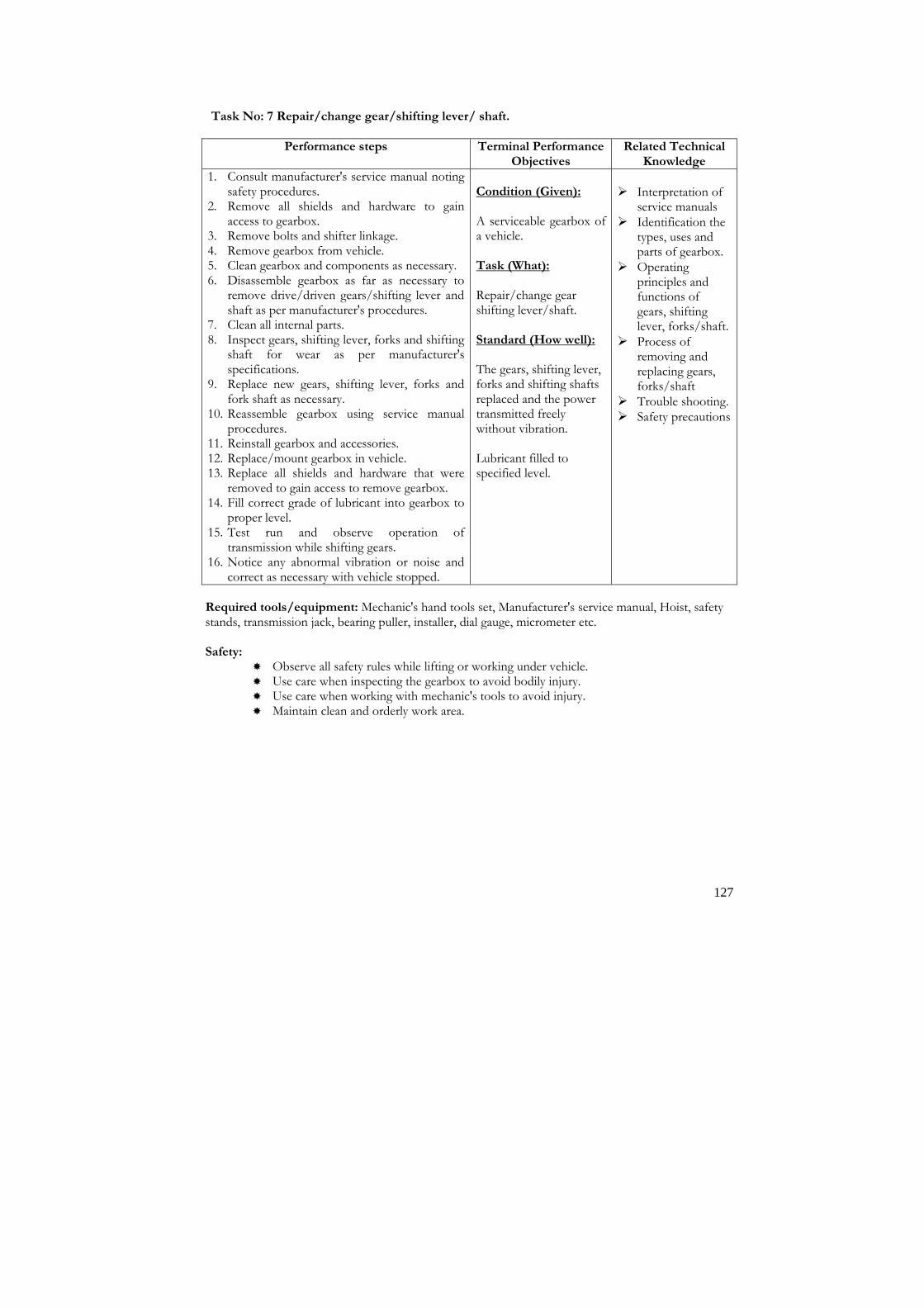
127
Task No: 7 Repair/change gear/shifting lever/ shaft.
Performance steps Terminal Performance Objectives
Related Technical Knowledge
1. Consult manufacturer's service manual noting safety procedures.
2. Remove all shields and hardware to gain access to gearbox.
3. Remove bolts and shifter linkage. 4. Remove gearbox from vehicle. 5. Clean gearbox and components as necessary. 6. Disassemble gearbox as far as necessary to
remove drive/driven gears/shifting lever and shaft as per manufacturer's procedures.
7. Clean all internal parts. 8. Inspect gears, shifting lever, forks and shifting
shaft for wear as per manufacturer's specifications.
9. Replace new gears, shifting lever, forks and fork shaft as necessary.
10. Reassemble gearbox using service manual procedures.
11. Reinstall gearbox and accessories. 12. Replace/mount gearbox in vehicle. 13. Replace all shields and hardware that were
removed to gain access to remove gearbox. 14. Fill correct grade of lubricant into gearbox to
proper level. 15. Test run and observe operation of
transmission while shifting gears. 16. Notice any abnormal vibration or noise and
correct as necessary with vehicle stopped.
Condition (Given): A serviceable gearbox of a vehicle. Task (What): Repair/change gear shifting lever/shaft. Standard (How well): The gears, shifting lever, forks and shifting shafts replaced and the power transmitted freely without vibration. Lubricant filled to specified level.
� Interpretation of
service manuals � Identification the
types, uses and parts of gearbox.
� Operating principles and functions of gears, shifting lever, forks/shaft.
� Process of removing and replacing gears, forks/shaft
� Trouble shooting. � Safety precautions
Required tools/equipment: Mechanic's hand tools set, Manufacturer's service manual, Hoist, safety stands, transmission jack, bearing puller, installer, dial gauge, micrometer etc. Safety:
� Observe all safety rules while lifting or working under vehicle. � Use care when inspecting the gearbox to avoid bodily injury. � Use care when working with mechanic's tools to avoid injury. � Maintain clean and orderly work area.
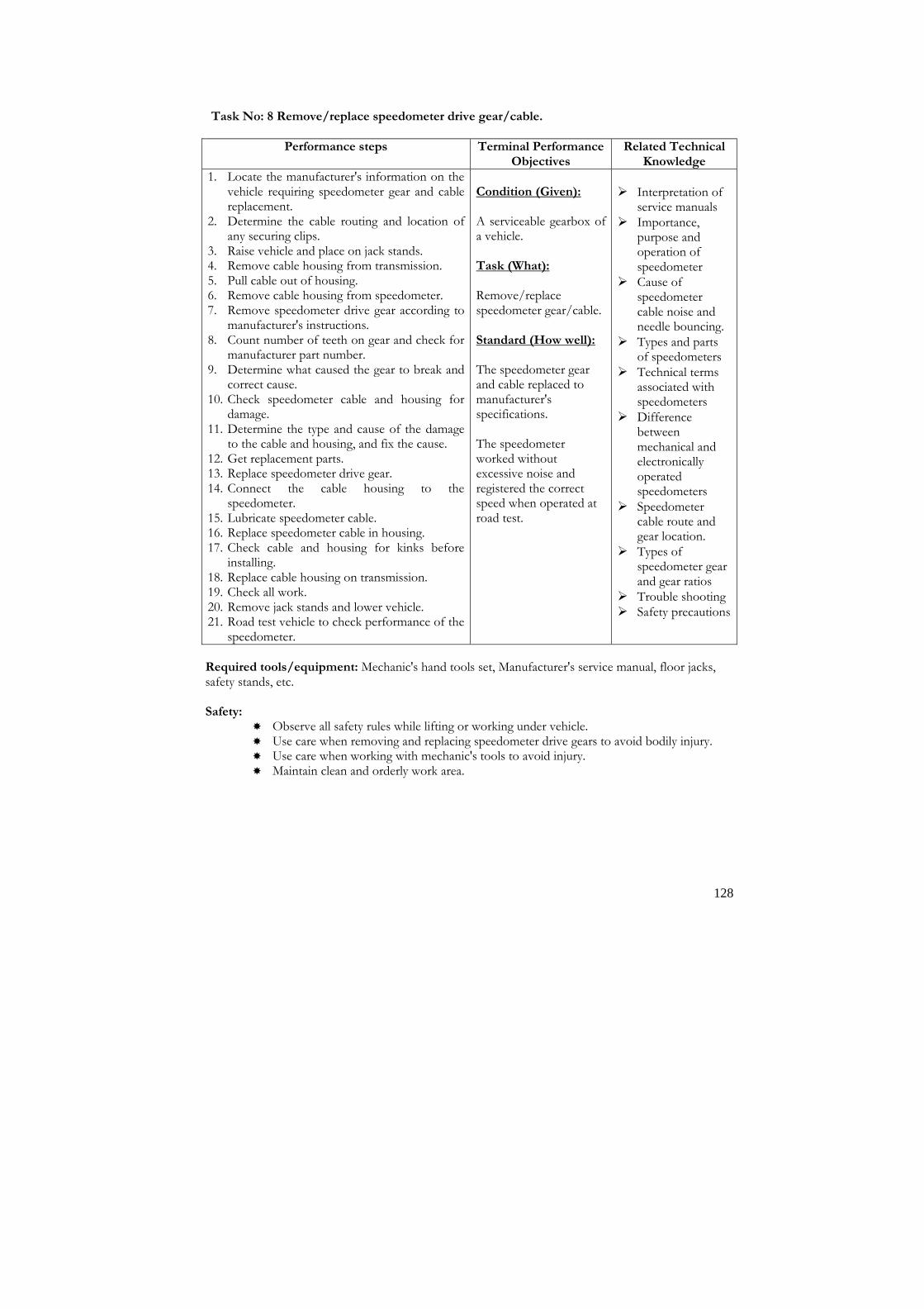
128
Task No: 8 Remove/replace speedometer drive gear/cable.
Performance steps Terminal Performance Objectives
Related Technical Knowledge
1. Locate the manufacturer's information on the vehicle requiring speedometer gear and cable replacement.
2. Determine the cable routing and location of any securing clips.
3. Raise vehicle and place on jack stands. 4. Remove cable housing from transmission. 5. Pull cable out of housing. 6. Remove cable housing from speedometer. 7. Remove speedometer drive gear according to
manufacturer's instructions. 8. Count number of teeth on gear and check for
manufacturer part number. 9. Determine what caused the gear to break and
correct cause. 10. Check speedometer cable and housing for
damage. 11. Determine the type and cause of the damage
to the cable and housing, and fix the cause. 12. Get replacement parts. 13. Replace speedometer drive gear. 14. Connect the cable housing to the
speedometer. 15. Lubricate speedometer cable. 16. Replace speedometer cable in housing. 17. Check cable and housing for kinks before
installing. 18. Replace cable housing on transmission. 19. Check all work. 20. Remove jack stands and lower vehicle. 21. Road test vehicle to check performance of the
speedometer.
Condition (Given): A serviceable gearbox of a vehicle. Task (What):
Remove/replace speedometer gear/cable. Standard (How well): The speedometer gear and cable replaced to manufacturer's specifications. The speedometer worked without excessive noise and registered the correct speed when operated at road test.
� Interpretation of
service manuals � Importance,
purpose and operation of speedometer
� Cause of speedometer cable noise and needle bouncing.
� Types and parts of speedometers
� Technical terms associated with speedometers
� Difference between mechanical and electronically operated speedometers
� Speedometer cable route and gear location.
� Types of speedometer gear and gear ratios
� Trouble shooting � Safety precautions
Required tools/equipment: Mechanic's hand tools set, Manufacturer's service manual, floor jacks, safety stands, etc. Safety:
� Observe all safety rules while lifting or working under vehicle. � Use care when removing and replacing speedometer drive gears to avoid bodily injury. � Use care when working with mechanic's tools to avoid injury. � Maintain clean and orderly work area.

129
Task No: 9 Assemble gearbox.
Performance steps Terminal Performance Objectives
Related Technical Knowledge
1. Follow the manufacturer's recommended order of parts removal. If no manual is available, study of the method of construction. This will provide clues as to which part should be removed first, second etc. Careful study will also usually indicate how the parts must be removed.
2. Remove all shields and hardware to gain access to gear box housing.
3. Clean components as necessary. 4. Remove gearbox from vehicle. 5. Disassemble gearbox cover and note down
the construction and arrangements of shift mechanism as per manufacturer's procedures.
6. Note down the types of gear used, bearing arrangements, gear trains and how different gears are engaged.
7. Note how the synchronizer unit functions. 8. Dismantle all parts such as input/top shaft,
output/main shaft assembly, counter shaft assembly, reverse idler gear assembly, synchronizer assembly etc.
9. Inspect all parts as per manufacturer's specifications.
10. Replace worn parts with new. 11. Reassemble gearbox using service manual
procedures. 12. Replace/mount gearbox in vehicle. 13. Replace all shields and sheet metal that are
removed to gain access to remove gearbox. 14. Fill correct grade of lubricant to proper level. 15. Test run and observe operation of
transmission while shifting gears.
Condition (Given): A serviceable gearbox of a vehicle. Task (What): Dismantle gearbox. Standard (How well): The gearbox assembled according to manufacturer's procedures and specifications. The power transmission must be freed from noise, vibration while driving.
� Interpretation of
service manuals � Importance,
necessity and uses of gearbox.
� Working principles, functions and types of gearbox.
� Parts identifications, inspection and assembling process.
� Trouble shooting. � Safety precautions
Required tools/equipment: Mechanic's hand tools set, Manufacturer's service manual, transmission jack, Hoist, safety stands, dial indicator, micrometer etc. Safety:
� Observe all safety rules while lifting or working under vehicle. � Use care when removing and replacing gearbox to avoid bodily injury. � Use care when working with mechanic's tools to avoid injury. � Maintain clean and orderly work area.

130
Task No: 10 Change transmission gear oil.
Performance steps Terminal Performance Objectives
Related Technical Knowledge
1. Ensure that the gearbox is warm up to pour
the oil. 2. Lift the vehicle and raise if required. 3. Clean the surrounding area of gearbox filler
and drain plug. 4. Place clean tray/jar under the drain plug. 5. Unscrew and remove the drain plug. 6. Remove the filler plug. 7. Wait 15 to 30 minutes to drain the gear oil. 8. Plug up the drain plug. 9. Tighten the drain plug. 10. Refill the specified grade of oil. 11. Wait 5 to 15 minutes to check the oil level. 12. Check the oil level. 13. Top up the gear oil if level is low. 14. Tighten the filler plug.
Condition (Given): A serviceable vehicle in a workshop. Task (What): Change transmission gear oil. Standard (How well): The oil changed with in specified level.
� Importance and
identification of lubricating oil/ lubricants
� Types of lubricant. � Properties of gear
oil � Grade and viscosity � SAE and API
specification
Required tools/equipment: Mechanics' hand tools set, drain plug wrench, tray/jar, filler pipe, and
funnel Safety:
� Never use loose or unsealed gear oil. � Always use correct grade and viscosity of gear oil to change. � Use care when removing and replacing speedometer drive gears to avoid bodily injury. � Use care when working with mechanic's tools to avoid injury. � Maintain clean and orderly work area.

131
Module: 3 Sub Module 2
Differential and Transaxle Description: This sub module intends to provide knowledge and skills about auto differential and transaxle system. Objectives: After completion of this module the trainees will be able to: 1. Be familiar with differential & transaxle 2. Maintain differential & transaxle Duration: 25 hours (5 hours theory and 20 hours practical) Tasks:
1. Remove/replace axle seal/bearings. 2. Replace crown wheel and pinion. 3. Replace bevel kit. 4. Overhaul/rebuild differentials. 5. Remove/replace transaxle assembly. 6. Repair/replace front wheel drive axle assembly. 7. Overhaul four wheel drive (4WD) transmission.

132
Task No: 1 Remove/replace axle seal/bearings.
Performance steps Terminal Performance Objectives
Related Technical Knowledge
1. Locate the manufacturer's information on the vehicle requiring axle-bearing replacement.
2. Place vehicle on lift and raise. 3. Remove rear wheels. 4. NOTE: Most axles are either held on by a
retaining plate or held in by c-clips inside the differential housing.
5. Drain lubrication from differential. 6. Remove axle-retaining plate from housing. 7. Remove axle seal by using axle seal remover. 8. Remove axle-bearing retainer. 9. Remove axle bearing from axle or housing
using press. 10. Lay cloth over bearing while pressing off
because bearings are made of tapered steel and may shatter easily.
11. Check axle bearings for wear and replace if necessary.
12. Clean axle shaft. 13. Check for replacement bearings and seal part
numbers. 14. Get necessary replacement parts. 15. Install axle seal. 16. Install axle-retaining plate in differential
housing. 17. Press new bearing on axle. 18. Replace axle seal and retainer. 19. Replace axle-retaining plate. 20. Replace new lubricant in differential. 21. Check all work. 22. Replace rear wheels. 23. Lower vehicle. 24. Road test vehicle to check performance and
to determine if the seals will leak.
Condition (Given): A vehicle in a workshop.
Task (What): Replace axle seals. Replace axle bearings. Standard (How well): The axle seals and bearings replaced as per manufacturer's specifications. Upon completion there must be no leaks from the axle seal after the vehicle has been driven. The axle assembly must operate according to manufacturer's specifications.
� Interpretation of
service manuals � Importance,
purpose, functions, types and parts of axle assemblies
� Difference between 'live' and 'dead' axles.
� Technical terms associated with axles, seals and bearings
� Working principles and function of seals and bearings
� Causes and effects of axle seal and bearing failure
� Causes of axle or bearing noises
� Trouble shooting. � Safety precautions
Safety:
� Ensure that the vehicle is on a level surface. � Always ensure that wheels remaining on ground are firmly chocked. � Never work on a vehicle supported only on jacks. � Use care when working with mechanic's hand tools. � Use care when removing and replacing axle seal and bearings to avoid bodily injury. � Maintain clean and orderly work area.

133
Task No: 2 Replace crown wheel and pinion.
Performance steps Terminal Performance Objectives
Related Technical Knowledge
1. Locate the manufacturer's information on vehicle requiring removal and replacement of the differential.
2. Place vehicle on lift and raise. 3. Drain the differential. 4. Support differential with jack. 5. Remove rear tyres and wheels. 6. Remove rear brake assemblies. 7. Remove all backing plate bolts. 8. Remove rear axles. 9. Remove drive shaft with joint at differential. 10. Remove bolts and nits holding differential to
suspension. 11. Remove differential from vehicle and lower. 12. Repair of replace differential. 13. Lift new or repaired differential into place. 14. Replace bolts or nuts holding differential to
suspension. 15. Replace drive shaft with joint. 16. Replace both axles. 17. Replace brake assemblies. 18. Fill differential with lubricant. 19. Check all work. 20. Replace wheels. 21. Remove differential jack and lower vehicle. 22. Road test vehicle to check performance.
Condition (Given): A serviceable differential.
Task (What): Replace crown wheel and pinion of differential
Standard (How well): The differential assembly removed and replaced according to manufacturer's specifications and procedures.
� Interpret service
manuals � Importance, purpose
and functions of differential
� Technical terms associated with differentials and rear axle assemblies
� Causes and effects of differential malfunctions
� Trouble shooting � Safety precautions
Required tools/equipment: Mechanic's hand tools set, Manufacturer's service manual, Hoist, safety stands, lug wrench, seal remover, seal installer, slide hammer, press, tray or jar, funnel etc. Safety:
� Ensure that the vehicle is on a level surface. � A vehicle supported by a jack or bricks is a potential danger. � Always ensure that wheels remaining on ground are firmly chocked. Never work on a
vehicle supported only on jacks. � Use care when working with mechanic's hand tools. � Use care when removing and replacing spring leaves to avoid bodily injury. � Maintain clean and orderly work area.

134
Task No: 3 Replace bevel kit.
Performance steps Terminal Performance Objectives
Related Technical Knowledge
1. Locate the manufacturer's information on vehicle requiring removal and replacement of the differential.
2. Place vehicle on lift and raise. 3. Drain the differential. 4. Support differential with jack. 5. Remove rear tyres and wheels. 6. Remove rear brake assemblies. 7. Remove all backing plate bolts. 8. Remove rear axles. 9. Remove drive shaft with joint at
differential. 10. Remove bolts and nuts holding carrier
assembly to axle housing. 11. Remove carrier assembly from axle
housing and lower. 12. Repair of replace differential. 13. Lift new or repaired differential carrier
assembly into place. 14. Install carrier in differential housing. 15. Replace drive shaft with joint at
differential. 16. Replace both axles. 17. Replace backing plates bolts. 18. Replace brake assemblies. 19. Fill differential with lubricant. 20. Check all work. 21. Replace wheels. 22. Remove jack and lower vehicle. 23. Road test vehicle to check performance.
Condition (Given): A serviceable differential.
Task (What): Remove/change bevel kit.
Standard (How well): All backing plate bolts removed. Differential bevel kit replaced. Brake assemblies replaced.
� Interpret service
manuals � Importance,
identification, types and parts of differential
� Operating principles of bevel assembly
� Technical terms associated with differentials
� Trouble shooting � Safety precautions
Required tools/equipment: Mechanic's hand tools set, Manufacturer's service manual, Hoist, safety stands, lug wrench, seal remover, seal installer, slide hammer, press, tray or jar, funnel etc. Safety:
� Ensure that the vehicle is on a level surface. � A vehicle supported by a jack or bricks are a potential danger. � Chocks must be placed under one of the wheels not being raised. � Never work on a vehicle supported only on jacks. � Use care when working with mechanic's hand tools. � Use care when removing and replacing spring leaves to avoid bodily injury. � Maintain clean and orderly work area.

135
Task No: 4 Overhaul/rebuild differential.
Performance steps Terminal Performance Objectives
Related Technical Knowledge
1. Locate the manufacturer's information on vehicle requiring rebuilding of the differential.
2. Place vehicle on lift and rise. 3. Drain the differential. 4. Support differential with jack. 5. Remove rear tyres and wheels. 6. Remove rear brake assemblies. 7. Remove all backing plate bolts. 8. Remove rear axles. 9. Remove drive shaft with joint at
differential. 10. Remove bolts or nuts holding carrier
assembly to axle housing. 11. Remove carrier assembly from axle
housing and lower. 12. Clean carrier assembly. 13. Check differential endplay and run out
before disassembly. 14. Disassemble differential carrier assembly. 15. Mark the adjusting caps and nuts for
identification. 16. Remove adjusting caps bolts. 17. Remove ring gear and carrier assembly by
lifting out of housing. 18. Remove drive pinion nuts. 19. Remove yoke from pinion shaft. 20. Remove pinion seal. 21. Remove pinion and pinion bearings. 22. Remove axle/bevel gear and star/spider
gears. 23. Clean all parts except axle sealed type
bearings. 24. Inspect all gears. 25. Inspect all splines. 26. Inspect all bearings. 27. Check differential case and carrier
assembly for distortion. 28. Check manufacturer's specifications to
identify part numbers for necessary replacement parts.
29. Get all necessary replacement parts. 30. Replace rear bearings on pinion shaft. 31. Install pinion shaft in housing, install outer
or front bearing and yoke flange. 32. Preload bearings to manufacturer's
specifications with new crush rings.
Condition (Given): A serviceable differential.
Task (What): Overhaul/rebuild differential.
Standard (How well): The differential endplay and backlash adjusted. The differential assembly rebuilt according to manufacturer's specifications and procedures.
� Interpret service
manuals � Introduction,
purpose and functions of differential and axle assembly
� Working principles, functions and types of differential
� Technical terms associated with differentials and rear axle assemblies
� Back lash-adjusting process
� Causes of differential malfunction, gear wear and failure
� Trouble shooting � Safety precautions

136
33. Remove yoke and install pinion seal. 34. Assemble ring gear, spider and axle gears. 35. Install assembly in differential making sure
that the adjusting caps and nuts are on the right marked side.
36. Adjust ring gear and pinion backlash to manufacturer's specifications.
37. Use white lead or grease on ring gear to check contact pattern by rotating ring gear both ways several times.
38. Lift repaired differential carrier assembly into place.
39. Replace bolts and nuts holding carrier assembly to differential housing.
40. Replace drive shaft with joints at differential.
41. Replace both axles. 42. Replace backing plate bolts. 43. Replace brake assemblies. 44. Fill differential with lubricant. 45. Check all work. 46. Replace wheels. 47. Remove differential jack and lower
vehicle. 48. Road test vehicle to check performance. Required tools/equipment: Mechanic's hand tools set, Manufacturer's service manual, Hoist, safety stands, dial gauge with magnetic stand, lug wrench, seal remover, seal installer, slide hammer, press, tray or jar, funnel etc. Safety:
� Ensure that the vehicle is on a level surface. � A vehicle supported by a jack or bricks are a potential danger. � Always ensure that wheels remaining on ground are firmly chocked. Chocks must be
placed under one of the wheels not being raised. � Never work on a vehicle supported only on jacks. � Use care when working with mechanic's hand tools. � Use care when removing and replacing differential to avoid bodily injury. � Maintain clean and orderly work area.

137
Task No: 5 Remove/replace transaxle assembly.
Performance steps Terminal Performance Objectives
Related Technical Knowledge
1. Locate the manufacturer's information on vehicle requiring transaxle replacement.
2. Place vehicle on lift and raise. 3. Drain the differential. 4. Support differential with jack. 5. Remove front tyres and wheels. 6. Remove lower end of front shocks. 7. Remove front springs. 8. Lift front axle assembly up and remove,
repeat for other side. 9. Remove controls and accessories linking
transaxle to vehicle. 10. Remove bolts attaching transaxle to block. 11. Chain transaxle assembly to jack stand. 12. Lower/remove transaxle from vehicle. 13. Disassemble transaxle assembly. NOTE: Basic transaxle designs are similar, however disassembly procedures and assembly procedures vary widely among the different makes and models. It is recommended that a service manual be used. 14. Clean all parts with solvent. 15. Inspect all parts. 16. Note parts, which need replacement. 17. Look up/check manufacturer's
specifications and parts number for all necessary replacement parts.
18. Get all necessary replacement parts. 19. Reassemble transaxle. 20. Chain new or replacement transaxle to
jack stand. 21. Lift and replace transaxle in vehicle. 22. Replace bolts attaching transaxle to block
and remove safety chains. 23. Replace controls and accessories to
transaxle. 24. Replace axle assemblies on both sides. 25. Replace front springs. 26. Replace lower ends of front shocks. 27. Fill transaxle with lubricant. 28. Check all work. 29. Replace front tyres and wheels. 30. Remove jack and lower vehicle. 31. Road test vehicle to check performance.
Condition (Given): A serviceable transaxle. Task (What): Repair/replace transaxle. Standard (How well): The transaxle assembly removed and replaced according to manufacturer's specifications and procedures.
� Interpretation of
service manuals � Introduction,
importance, functions of final drive and transaxle assemblies
� Working principles, functions and types of transaxle
� Technical terms associated with transaxle assemblies
� Process of removing and transaxle
� Causes and effects of transaxle failure
� Trouble shooting � Safety precautions
Required tools/equipment: Mechanic's hand tools set, Manufacturer's service manual, Hoist, safety stands, lug wrench, seal remover, seal installer, slide hammer, press, tray or jar, funnel etc.

138
Safety:
� Ensure that the vehicle is on a level surface. � A vehicle supported by a jack or bricks are a potential danger. � Always ensure that wheels remaining on ground are firmly chocked. Chocks must be
placed under one of the wheels not being raised. � Never work on a vehicle supported only on jacks. � Use care when working with mechanic's hand tools. � Use care when removing and replacing transaxle to avoid bodily injury. � Maintain clean and orderly work area.

139
Task No: 6 Repair/replace front wheel drive axle assembly.
Performance steps Terminal Performance Objectives
Related Technical Knowledge
1. Locate the manufacturer's information on vehicle requiring removal and replacement of front wheel drive axle assemblies.
2. Jack the vehicle and place on jack stands.
3. Remove front wheels and tyres. 4. Remove front drive shaft from front
differential.
5. Drain front differential. 6. Support front differential with jack.
7. Remove lower end of front shocks. NOTE: Basic front wheel drive axle designs are similar; however disassembly procedures and assembly procedures vary widely among the different makes and models. It is recommended that a service manual be used. 8. Disconnect steering gear linkage.
9. Disconnect front brake line at flex line. 10. Remove front springs.
11. Remove front wheel drive axle assembly.
12. Clean all parts.. 13. Inspect all parts. 14. Note parts, which need replacement.
15. Look up/check manufacturer's specifications and parts number for all necessary replacement parts.
16. Get all necessary replacement parts.
17. Lift front wheel drive front axle assembly into place.
18. Replace axle assemblies on both sides.
19. Replace front springs. 20. Reconnect front brake lines. 21. Fill brake master cylinder and bleed
brakes.
22. Refill brake master cylinder. 23. Reconnect steering gear linkage. 24. Replace lower ends of front shocks. 25. Fill differential with lubricant. 26. Connect front drive shaft to front
differential. 27. Install front tyres and wheels. 28. Check all work. 29. Lower vehicle and remove jack. 30. Road test vehicle to check performance.
Condition (Given): A front wheel drive vehicle. Task (What): Repair/replace front wheel drive axle assembly. Standard (How well): Front wheel drive axle assemblies removed and replaced according to manufacturer's specifications and procedures.
� Interpret service
manuals � Importance,
purpose, function types and parts of front wheel drive axle assemblies
� Operating principles and function of differentials and front wheel drive axle assemblies.
� Technical terms associated with front wheel drive axle assemblies.
� Process of removing and replacing front wheel drives axle assemblies
� Causes and effects of front axle and bearing failure
� Trouble shooting � Safety precautions

140
Required tools/equipment: Mechanic's hand tools set, Manufacturer's service manual, Hoist, safety stands, transmission jack, lug wrench, seal remover, seal installer, slide hammer, press, tray or jar, funnel etc. Safety:
� Ensure that the vehicle is on a level surface. � A vehicle supported by a jack or bricks are a potential danger. � Always ensure that wheels remaining on ground are firmly chocked. Chocks must be
placed under one of the wheels not being raised. � Never work on a vehicle supported only on jacks. � Use care when working with mechanic's hand tools. � Use care when removing and replacing front wheel drive axle to avoid bodily injury.
Maintain clean and orderly work area.

141
Task No: 7 Overhaul four wheel drive (4WD) transmission.
Performance steps Terminal Performance Objectives
Related Technical Knowledge
Dismounting 1. Disconnect negative cable at battery 2. Drain transfer oil 3. Give match marks on each joint flange and
propeller shaft 4. Remove securing bolts from each flange
connection server 3 propeller shafts from transfer gear box and suspend propeller shafts with a wire hook.
5. Disconnect speedometer from transfer by loosing securing bolts.
6. Disconnect 4WD switch wire at coupler 7. Remove shift lever from shaft and select arm
by removing pin. 8. Remove mounting nuts 9. Remover transfer with mountings from body 10. Remove mountings from transfer. Disassembly 1. Remove spring pin from shift and select arm 2. Remove 4WD switch and take out steel ball 3. Remove locating spring bolt and take out
locating spring and steel ball 4. Remove speedometer driven gear 5. Remove rear output side flange. To lock
flange use special tool. With flange locked, remove flange bolt.
6. Remove rear case bolts and separate case by using special tool
7. Remove oil seal from rear case by using special tool
8. Remove circlip and then remover bearing 9. Pull out speedometer drive gear 10. Remove flange To lock flange use special
tool. With flange locked, remove flange nut. 11. Remove transfer output gear washer and then
remove drive chain, input shaft and ring and sprocket gear assy as an assembly
12. Remove needle roller bearing 13. Pull out bearings from input shaft 14. Disassemble ring and sprocket gear assy by
removing circlip 15. Remove interlock bolt 16. Pull out interlock block and shit fork shaft by
turning it 17. Remove planetary gear unit and Hi-Lo shift
fork 18. Disassemble planetary gear unit by removing
Condition (Given): A serviceable transfer of a vehicle. Task (What): Overhaul four wheel drive (4WD) transmission Standard (How well): Four wheel drive transmission overhauled according to specification.
� Interpretation of
service manuals � Importance,
necessity and uses of transfer case
� Working principles, functions of transfer case.
� Parts identifications, inspection and assembling process.
� Trouble shooting � Safety precautions

142
circlip 19. Pull out output rear shaft 20. Remove lock up plate and oil gutter by
removing bolts 21. Remove reduction clutch sleeve and 2-4 shift
fork 22. Remove output front shaft 23. By using bearing puller and press, remove
bearing from output front shaft 24. Remove oil seal from front shaft 25. By using screw driver, remove shift for shaft
oil seal 26. Remove circlip and then remove bearing from
front case Inspection 1. Check each ball bearing for smooth rotation. 2. Check needle bearing and bearing contacting
surface for damage 3. check gear tooth surface and shift mechanism
I the same manner as with transmission 4. Check each spring for distortion or breakage 5. Check drive chain and sprocket 6. Check oil seal for leakage and its lip for
excessive hardness Assembly 1. Install bearing to front case by using special
tool and press 2. Fix output front shaft with circlip 3. Install oil seal to front case. Apply grease to
each oil seal lip. 4. Install bearing to output shaft 5. Install output front shaft to front case 6. Install flange, tighten flange nut and cauk nut 7. Install reduction clutch sleeve and 2-4 shift
fork 8. Install lock up plate and oil gutter and tighten
bolts 9. Install output rear shaft to output front shaft 10. Assemble planetary gear assy. Shift spacer,
needle roller bearing, planetary sun gear and thrust washer and secure then with circlip\
11. Install planetary gear unit and Hi-Lo shift fork to output rear shaft as an assembly
12. Install shift and select lever to shift fork shaft and fix it with spring pin
13. Install interlock block and shift for shaft to front case
14. Fix interlock block with interlock bolt by turning interlock block and shift fork shaft
15. Install bearing to input shaft by using bearing puller and press
16. Assemble ring gear and sprocket gear and secure then with circlip
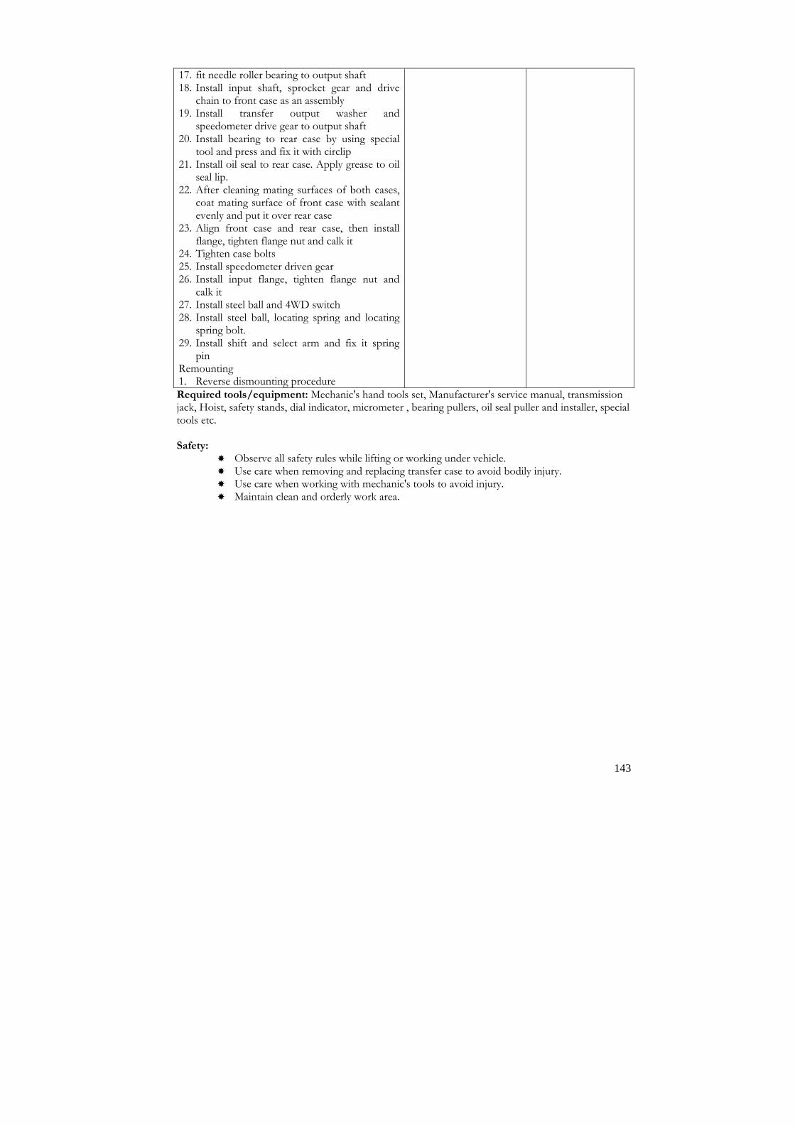
143
17. fit needle roller bearing to output shaft 18. Install input shaft, sprocket gear and drive
chain to front case as an assembly 19. Install transfer output washer and
speedometer drive gear to output shaft 20. Install bearing to rear case by using special
tool and press and fix it with circlip 21. Install oil seal to rear case. Apply grease to oil
seal lip. 22. After cleaning mating surfaces of both cases,
coat mating surface of front case with sealant evenly and put it over rear case
23. Align front case and rear case, then install flange, tighten flange nut and calk it
24. Tighten case bolts 25. Install speedometer driven gear 26. Install input flange, tighten flange nut and
calk it 27. Install steel ball and 4WD switch 28. Install steel ball, locating spring and locating
spring bolt. 29. Install shift and select arm and fix it spring
pin Remounting 1. Reverse dismounting procedure Required tools/equipment: Mechanic's hand tools set, Manufacturer's service manual, transmission jack, Hoist, safety stands, dial indicator, micrometer , bearing pullers, oil seal puller and installer, special tools etc. Safety:
� Observe all safety rules while lifting or working under vehicle. � Use care when removing and replacing transfer case to avoid bodily injury. � Use care when working with mechanic's tools to avoid injury. � Maintain clean and orderly work area.

144
Module: 4
Auto Service Mechanic Description This module is designed to equip trainees with the skills and knowledge on Auto Service as a specialized module related to the occupation. This module intends to provide skills and knowledge on various types of servicing such as changing, adjusting, testing, and setting. Objectives: After completion of this module the trainees will be able to: 1. Identify serviceable parts 2. Service vehicle Duration: 50 hours (10 hours theory and 40 hours practical) Competencies
1. Wash Vehicle. 2. Grease with grease gun. 3. Lubricate with oilcan. 4. Change fuel filter. 5. Change oil filter. 6. Change engine oil 7. Change Coolant level. 8. Clean/change air filter. 9. Drain off condenses water from compressed air. 10. Change thermostats. 11. Grease hub. 12. Adjust brake. 13. Adjust Clutch. 14. Adjust crown wheel thrust pad. 15. Adjust wheel alignment. 16. Service battery. 17. Adjust fan belts. 18. Tighten underbody nuts and bolts. 19. Adjust tappet/valve clearance. 20. Test fuel injector. 21. Adjust RPM. 22. Change differential oil. 23. Set/ adjust air pressure. 24. Add/change steering oil.
25. Adjust wheel hub play.

145
Task No: 1 Wash Vehicle
Performance steps Terminal Performance Objectives
Related Technical Knowledge
1. Park the vehicle in service bay.
2. Apply hand brake or place choke to the wheel.
3. Disconnect battery negative terminal. 4. Remove floor mats from the vehicle.
5. Clean the interior of the vehicle.
6. Clean the interior floor with vacuum cleaner.
7. Lift the hydraulic ramp as required height.
8. Adjust the pressure of water spray nozzle in water pump or hosepipe.
9. Wash the vehicle by using spray nozzle. 10. Clean/ wash the floor mats and mattress.
11. Wipe up the body of the vehicle with soft cloth and liquid soap or detergent.
12. Wash/Remove dry soil or mud under the chassis.
13. Wash the vehicle thoroughly.
14. Wipe the wet water with soft cloth.
15. Wax the dashboard interior.
Condition (Given): A vehicle in washing bay. Task (What): Wash the vehicle. Standard (How well): The vehicle is washed and waxed according to performance guide.
� Handling of
vacuum cleaner. � Purpose,
importance and types of wax
� Liquid soap and detergent
� Handling of hydraulic ramp or washing bay
Required tools/equipment: Water pump, washing bay, Vacuum cleaner. Safety:
� Observe all safety rules while lifting and working under vehicle. � Observe great care when using chemical solvent to cleaning components. � Use care when using steam and chemical fumes to avoid eye and skin injury. � Use care when working with mechanic's tools to avoid injury. � Maintain clean and orderly work area.

146
Task No: 2 Grease with grease gun.
Performance steps Terminal Performance Objectives
Related Technical Knowledge
1. Park the vehicle in the workshop. 2. Pack the grease to the grease gun. 3. Locate the greasing points to the vehicle. 4. Keep the grease gun to the greasing nipple. 5. Pump the grease gun to the nipple 2 to 4
times for greasing. 6. Change the greasing nipple if the greasing
not complete. 7. Repeat the Performance steps for following
greasing points. 8. Grease remote gear shifting linkage. 9. Grease king pins. 10. Grease tie rod ends/ball joints. 11. Grease drag links ends. 12. Grease steering knuckle joints. 13. Grease front spring pins. 14. Grease rear spring pins. 15. Grease propeller shaft U-joints. 16. Grease propeller shaft sliding yoke. 17. Grease parking brake intermediate shaft
bushes. 18. Grease brake double levers. 19. Grease brake shaft bushes. 20. Grease clutch pedal bushing.
Condition (Given): A serviceable vehicle in a workshop. Task (What): Grease with grease gun. Standard (How well): All the greasing points of the vehicle greased properly.
� Importance and
identification greasing points
� Function of grease and greasing nipples.
� Properties and types of grease
� Identification, uses and types of grease gun
Required tools/equipment: Mechanics' hand tools set, grease gun, greasing nipple etc. Safety:
� Use care when working with mechanic's hand tools. � Use clean and orderly work area.

147
Task No: 3 Lubricate with oilcan.
Performance steps Terminal Performance Objectives
Related Technical Knowledge
1. Park the vehicle in the workshop. 2. Fill lube oil to the oil clean. 3. Locate the oiling points to the vehicle. 4. Clean the area of oiling and surroundings. 5. Oil to the points by using oilcan. 6. Repeat the Performance steps for following
points. 7. Oil control to injection points. 8. Oil ball joints of engine exhaust brake
linkage if fitted. 9. Oil central flap hinges and stay rods. 10. Oil to the linkage of clutch actuation and
parking brake. 11. Oil to the door hinges.
Condition (Given): A serviceable vehicle in a workshop. Task (What): Lubricate with oilcan. Standard (How well): All the oiling points of the vehicle lubricated properly.
� Importance and
identification oiling points
� Function of lubrication/ oil.
� Properties and types of oil
� Identification, uses and types of oil can.
Required tools/equipment: Mechanics' hand tools set, oil can, etc. Safety:
� Use care when working with mechanic's hand tools. � Use clean and orderly work area.

148
Task No: 4 Change fuel filter.
Performance steps Terminal Performance Objectives
Related Technical Knowledge
1. Determine the location and type of fuel filter
according to manufacturer's specifications for model, part, or serial number.
To remove/replace an in-line hose connected fuel filter follow these Performance steps. 1. Locate the fuel filter unit. 2. Remove the air cleaner assembly as required. 3. Loosen fuel filter attachment hardware as
required. 4. Disconnect fuel lines and discard clamps. 5. Remove fuel filter unit and dispose of properly. 6. Install replacement fuel filter unit in proper
direction of flow. 7. Reinstall and secure fuel lines with new hose
clamps. 8. Reinstall and secure attachment hardware as
required. 9. Replace air cleaner assembly as required. 10. Run engine, check for leaks and make any
adjustments necessary. To remove and replace an inverted nut (steel line) connected fuel filter follow these Performance steps.
1. Locate the fuel filter unit. 1. Remove the air cleaner assembly as required. 2. Loosen fuel filter attachment hardware as
required. 3. Position the correct size open end wrench on
the filter hex nut to hold the filter in position, and remove the steel line from the filter using suitable wrench.
4. Unscrew the fuel filter unit from the carburetor and dispose of property.
5. Install replacement fuel filter unit in proper direction of flow.
6. Reinstall and secure fuel line. 7. Reinstall and secure attachment hardware as
required. 8. Replace air cleaner assembly as required. 9. Run engine, check for leaks and make any
adjustments necessary. To remove and replace an in carburetor fuel filter follow these Performance steps. 1. Locate the fuel filter unit. 2. Remove the air cleaner assembly as required. 3. Loosen fuel filter attachment hardware as
Condition (Given): A serviceable vehicle in a workshop.
Task (What): Change the fuel filter. Remove/replace an in-line hose connected fuel filter. Remove/ replace an inverted nut (steel line) connected fuel filter. Remove/ replace an in carburetor fuel filter Standard (How well): An in-line hose connected fuel filter removed and replaced. An inverted nut (steel line) connected fuel filter removed and replaced An in carburetor fuel filter removed and replaced.
� Interpretation of
manufacturer's service manuals.
� Importance, purpose and function of fuel filters
� Types and parts of fuel filter
� Technical terms associated with fuel filters.
� Location of filters � Fuel filters
replacing procedure
� Trouble shooting
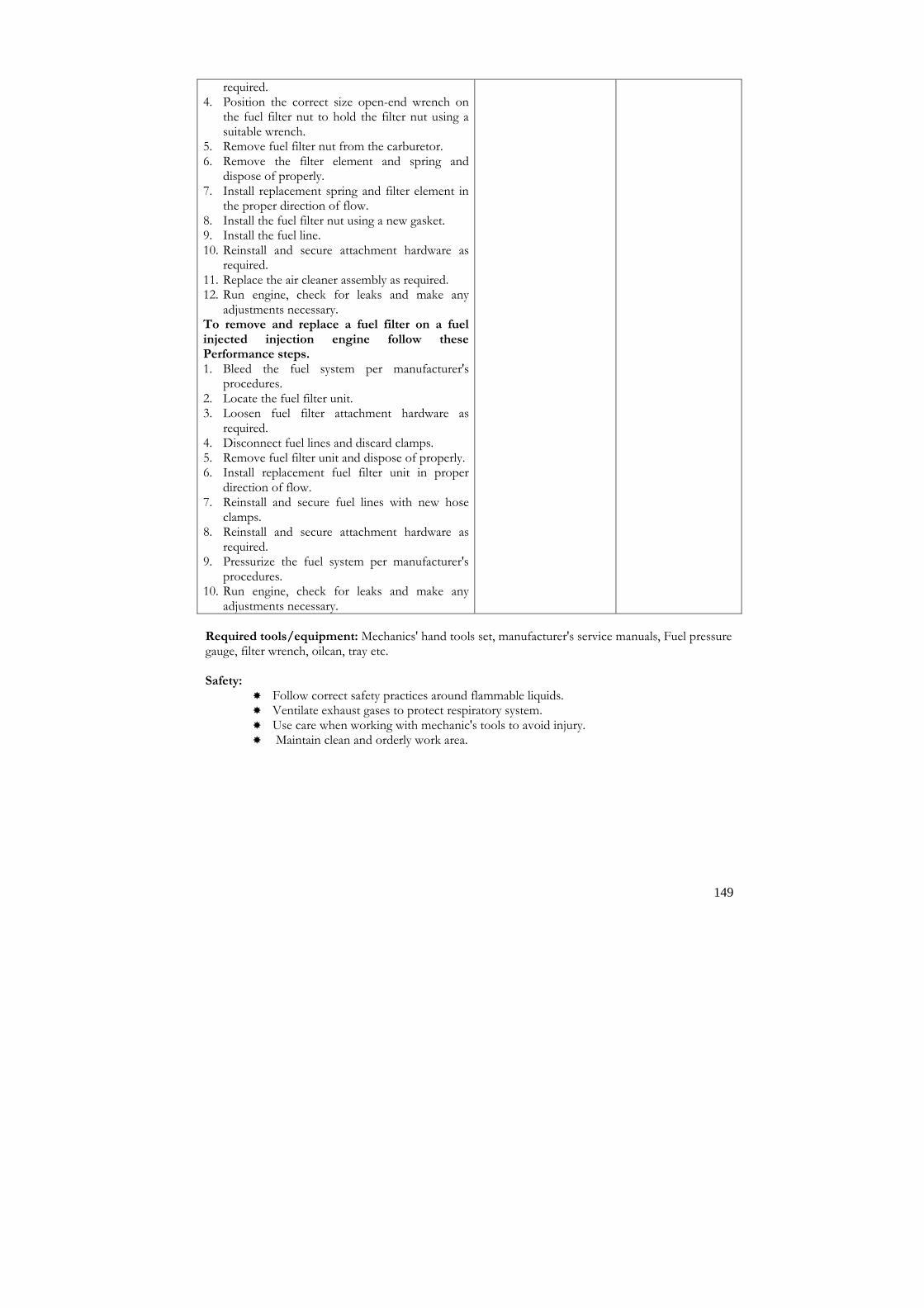
149
required. 4. Position the correct size open-end wrench on
the fuel filter nut to hold the filter nut using a suitable wrench.
5. Remove fuel filter nut from the carburetor. 6. Remove the filter element and spring and
dispose of properly. 7. Install replacement spring and filter element in
the proper direction of flow. 8. Install the fuel filter nut using a new gasket. 9. Install the fuel line. 10. Reinstall and secure attachment hardware as
required. 11. Replace the air cleaner assembly as required. 12. Run engine, check for leaks and make any
adjustments necessary. To remove and replace a fuel filter on a fuel injected injection engine follow these Performance steps. 1. Bleed the fuel system per manufacturer's
procedures. 2. Locate the fuel filter unit. 3. Loosen fuel filter attachment hardware as
required. 4. Disconnect fuel lines and discard clamps. 5. Remove fuel filter unit and dispose of properly. 6. Install replacement fuel filter unit in proper
direction of flow. 7. Reinstall and secure fuel lines with new hose
clamps. 8. Reinstall and secure attachment hardware as
required. 9. Pressurize the fuel system per manufacturer's
procedures. 10. Run engine, check for leaks and make any
adjustments necessary. Required tools/equipment: Mechanics' hand tools set, manufacturer's service manuals, Fuel pressure gauge, filter wrench, oilcan, tray etc. Safety:
� Follow correct safety practices around flammable liquids. � Ventilate exhaust gases to protect respiratory system. � Use care when working with mechanic's tools to avoid injury. � Maintain clean and orderly work area.

150
Task No: 5 Change oil filter.
Performance steps Terminal Performance Objectives
Related Technical Knowledge
1. Collect required tools and materials. 1. Warm up the engine for 5 minutes. 2. Place a clean tray under the drain plug. 3. Unscrew the drain plug. 4. Remove the drain plug. 5. Drain the engine oil in a jar or tray. 6. Remove oil filter. 7. Replace oil filter. 8. Plug the drain plug when oil stops
dropping. 9. Tighten the drain plug as per specified
torque according to the service manual. (Don't over tight)
10. Refill the specified grade of engine oil to the required level.
11. Wait 5 to 10 minutes for checking oil level.
12. Lift the dipstick and wipe it. 13. Check the oil level. 14. Refill the oil if the level is low. 15. Cap the filler cap. 16. Keep the jar or tray in proper place.
Condition (Given): A serviceable vehicle in a workshop. Task (What): Change the oil filter. Standard (How well): The oil filter changed and the oil level should be between the lower and upper level mark on the dipstick.
� Identification and
importance of oil filter
� Types of oil filter � Oil grade and
viscosity. � SAE and API
rating � Oil capacity of
different make and model of engine
Required tools/equipment: Mechanics' hand tools set, filter wrench, oilcan, tray/jar Safety:
� Ensure that the drain plug is properly tight and oil grade is correct as specified. � Ventilate solvent fumes to protect respiratory system. � Use safety practice when working with engine oil to avoid injury. � Use safety precautions when working with mechanic's hand tools. � Use clean and orderly work area.

151
Task No:6 Change engine oil
Performance steps Terminal Performance Objectives
Related Technical Knowledge
1. Collect required tools and materials. 2. Warm up the engine for 5 minutes. 3. Place a clean tray under the drain plug. 4. Change the oil filter if required. 5. Unscrew the drain plug. 6. Remove the drain plug. 7. Drain the engine oil in a jar or tray. 8. Uncap the oil filler cap 9. Flush the engine oil with flushing oil if
required. 10. Plug the drain plug when oil stops dropping. 11. Tighten the drain plug as per specified
torque according to the service manual. (Don't over tight)
12. Refill the specified grade of engine oil to the required level.
13. Wait 5 to 10 minutes for checking oil level. 14. Lift the dipstick and wipe it. 15. Check the oil level. 16. Refill the oil if the level is low. 17. Cap the filler cap. 18. Keep the jar or tray in proper place.
Condition (Given): A serviceable vehicle in a workshop. Task (What): Change the engine oil. Standard (How well): The engine oil is changed and the oil level should be between the lower and upper level mark on the dipstick.
� Identification and
importance of engine oil
� Function and properties of engine oil
� Oil grade and viscosity
� SAE and API rating
� Oil capacity of different make and model of engine
Required tools/equipment: Mechanics' hand tools set, filter wrench, oil can, tray/jar Safety:
� Follow correct safety practices around flammable liquids. � Ventilate exhaust gases to protect respiratory system. � Use care while flushing engine oil to danger. � Use care when working with mechanic's tools to avoid injury. � Maintain clean and orderly work area.

152
Task No: 7 Change Coolant level.
Performance steps Terminal Performance Objectives
Related Technical Knowledge
1. Collect required tools and materials. 2. Check the coolant level in the
radiator/reservoir. 3. Inspect the coolant properties. 4. Drain the radiator if required. 5. Prepare the specified quantity of
coolant/water according to service manual provided.
6. Add coolant if the level is low. 7. Check the leakage from radiator. 8. Check the radiator cap.
Condition (Given): A serviceable vehicle in a workshop. Task (What): Change coolant. Standard (How well): The coolant/ water changed with in specified level and ratio.
� Identification and
importance of engine coolant
� Types of coolant
and their properties � Coolant capacity
and proportion of coolant/water for different make and model of engine
Required tools/equipment: Mechanics' hand tools set, Coolant Tester, tray/jar Safety:
� Use safety precaution while testing coolant � Ventilate exhaust gases to protect respiratory system. � Use care while flushing engine oil to danger. � Use care when working with mechanic's tools to avoid injury. � Maintain clean and orderly work area.

153
Task No: 8 Clean/change air filter.
Performance steps Terminal Performance Objectives
Related Technical Knowledge
1. Determine type of air cleaner element using
manufacturer's specifications. To clean a dry type air cleaner elements follow these Performance steps. 1. Remove air cleaner element as per
manufacturer's procedure. 2. Strike dry element bottom side down on
floor or hard surface several times. 3. Blow out dirt with approved blowgun,
blowing from inside out. 4. Inspect filter by holding shop light inside
filter and verifying that light is visible through the filter element.
5. Reinstall air cleaner element into the air cleaner assembly.
To clean a oil bath type air cleaner element follow these Performance steps: 1. Remove air cleaner element as per
manufacturer's procedures. 2. Remove sponge wrapper or wire mesh
filter from dry inner element. 3. Wash sponge wrapper or wire mesh filter in
solvent or mineral spirits. 4. Add oil to wrapper or wire mesh filter
container/bowl as specified level. 1. Clean the dry inner filter as dry type filter
element. 2. Reinstall sponge wrapper over dry inner
element. 3. Reinstall air cleaner element into the air
cleaner assembly.
Condition (Given): A serviceable vehicle in a workshop. Task (What): Clean/change air filter. Standard (How well): The air cleaner unit cleaned according to manufacturer's specifications; unit cannot damage; airflow must not be restricted.
� Importance,
purpose and applications of air filters
� Technical terms associated with air filters
� Types and parts identification of air filters
� Air filters element cleaning technique.
� Operating principles and functions of the air filter
� Cause and effect of bad and dirty air filters
Required tools/equipment: Mechanics' hand tools set, Manufacturer's service manuals, source of
compressed air and blow gun, shop light, parts washing equipment as required, etc. Safety:
� Follow correct safety practices when using compressed air to avoid eye injury. � Use care when using solvents to avoid skin irritation and eye injury. � Ventilate solvent fumes to protect respiratory system. � Use safety precautions when working with mechanic's hand tools. � Use clean and orderly work area.

154
Task No: 9 Drain off condense water from compressed air.
Performance steps Terminal Performance Objectives
Related Technical Knowledge
1. Park the vehicle in a level surface. 2. Locate the water drain cock/plug. 3. Clean the drain cock and surroundings. 4. Loosen the drain cock/plug. 5. Drain the water from air tank and filter. 6. Plug the drain cock/plug after water drains
completely.
Condition (Given): A serviceable vehicle in a workshop. Task (What): Drains off condense water from compressed air. Standard (How well): The condensed water drain off and the air system free from water.
� Importance and
identification of air/pneumatic system.
� Terminology used in condensed water.
� Cause and effect of condense water in air system.
Required tools/equipment: Mechanics' hand tools set, Safety:
� Use care when working with mechanic's hand tools. � Use clean and orderly work area.

155
Task No: 10 Change thermostats.
Performance steps Terminal Performance Objectives
Related Technical Knowledge
1. Drain cooling system. 2. Remove thermostat housing and
thermostat. 3. Clean gasket surfaces. 4. Check thermostat for operation. 5. Install thermostat and housing using new
gasket. 6. Refill cooling system to proper level with
coolant. 7. Test pressure system for leaks. 8. Operate engine until it reaches normal
operating temperature. 9. Recheck coolant level.
Condition (Given): A vehicle in a workshop. Task (What): Change Thermostat. Standard (How well): The thermostat valve changed and the coolant temperature must record at manufacturer's recommended
temperature + or - 10° F.
� Interpretation of
service manuals � Importance,
identification, types and parts of cooling system
� Technical terms associated with cooling system.
� Function, importance and types of thermostat
� Thermostat testing process
� Troubleshooting
Required tools/equipment: Mechanic's hand tools set, Manufacturer's service manual, Temperature tester (thermometer), Heater, container, jar etc. Safety:
� Use care when removing/testing or working with thermostat to avoid injury. � Use care when working with mechanic's hand tools. � Maintain clean and orderly work area.

156
Task No: 11 Grease hub.
Performance steps Terminal Performance Objectives
Related Technical Knowledge
1. Lift the wheel that you want to hub
greasing. 2. Remove the wheel. 3. Remove the wheel axle/hub cover. 4. Remove the lock nut and lock washer. 5. Remove the check nut and washer. 6. Remove the taper roller/wheel hub
bearings. 7. Remove the axle shaft or spindle. 8. Clean all the components. 9. Fit the axle spindle to the housing. 10. Fit the wheel bearings. 11. Perform hub greasing. 12. Fit the thrust washer check nut. 13. Check the bearing preload. 14. Lock the bearing and axle shaft with lock
washer and lock nut. 15. Check the thrust play of wheel hub. 16. Add/remove thrust washer or shims to
increase/decrease the wheel axial play. 17. Repeat the step no. 15 and 16 until the play
is adjusted as specification. 18. Fit the wheel hub cover. 19. Fit the wheel. 20. Remove the jack.
Condition (Given): A serviceable vehicle in a workshop. Task (What): Grease wheel hub. Standard (How well): The wheel hub greased according to specification provided.
� Importance and
necessity of hub greasing
� Types of grease � Hub greasing
process � Trouble shooting � Safety precaution
Required tools/equipment: Mechanics' hand tools set, jack hydraulic or mechanical, wheel wrench,
bearing preload adjusting tool etc. Safety:
� Observe safety practices while lifting and working under vehicle. � Use safety practices while working with wheel to avoid injury. � Use safety precautions when working with mechanic's hand tools. � Use clean and orderly work area.

157
Task No: 12 Adjust brake.
Performance steps Terminal Performance Objectives
Related Technical Knowledge
1. Collect all the required tools and materials. 2. Check the fluid in master cylinder reservoir. 3. Top up if the level is low. 4. Bleed the air if required. 5. Jack up the wheel to make free from ground. 6. Turn the brake shoe adjuster to make wheel
tight. 7. Slacken the adjuster 2 to 4 turn that the
wheel rotates freely. 8. Repeat the step no. 5 to 7 for all wheels. 9. Check the brake pedal free play. 10. Adjust the master cylinder push rod if the
pedal free play is not specified. 11. Drive the vehicle. 12. Test the brake. 13. Adjust the brake if braking is not efficient. 14. Check the brake shoe lining and other
components if the adjustment not works.
Condition (Given): A serviceable vehicle in a workshop. Task (What): Adjust brake of given vehicle. Standard (How well): The brake adjusted and the vehicle is stopped in minimum braking distance. The pedal free play should be 15 +- 5 mm.
� Importance and
identification of braking system and their components
� Function and types of brake
� Importance and properties of brake fluid.
� Trouble shooting of brake system.
� Safety precaution
Required tools/equipment: Mechanics' hand tools set, brake adjusting tool or screwdriver, Brake
bleeding pipe, Jar etc. Safety:
� Observe all safety practice while lifting and working under vehicle. � Use care when working with mechanic's tools to avoid injury. � Use safety precautions while bleeding air and cleaning brake shoe lining. � Maintain clean and orderly work area.

158
Task No: 13 Adjust clutch
Performance steps Terminal Performance Objectives
Related Technical Knowledge
1. Collect all the required tools and
materials. 2. Check the fluid in clutch cylinder
reservoir. 3. Top up if the level is low. 4. Bleed the air if required. 5. Check the clutch pedal free play. 6. Adjust the clutch cylinder push rod if the
pedal free play is not specified. 7. Adjust the slave cylinder push rod if
applicable. 8. Check the clutch plate, clutch cylinder
and other components if the adjustment not works.
Condition (Given): A serviceable vehicle in a workshop. Task (What): Adjust clutch of given vehicle. Standard (How well): The clutch is adjusted and the pedal free play should be 15 +- 5 mm.
� Safety precaution. � Importance and
identification of clutch and their components.
� Function and types of clutch
� Importance and properties of brake/clutch fluid.
� Trouble shooting of clutch
Required tools/equipment: Mechanics' hand tools set, screwdriver, bleeding pipe, Jar etc. Safety:
� Observe all safety practice while lifting and working under vehicle. � Use care when working with mechanic's tools to avoid injury. � Maintain clean and orderly work area. � Use safety precautions while bleeding air and cleaning dust.

159
Task No: 14 Adjust crown wheel thrust pad.
Performance steps Terminal Performance Objectives
Related Technical Knowledge
1. Place vehicle on lift and raise. 2. Disconnect propeller shaft and U- joints. 3. Drain the differential. 4. Support differential with jack. 5. 6. Remove thrust pad and washer. 7. Remove drive pinion nuts. 8. Remove yoke from pinion shaft. 9. Remove pinion seal. 10. Remove pinion and pinion bearings. 11. Remove coupling/flange from drive
pinion. 12. Check manufacturer's specifications to
identify part numbers for necessary replacement parts.
13. Get all necessary replacement parts. 14. Replace rear bearings on pinion shaft. 15. Install pinion shaft in housing, install
outer or front bearing and yoke flange. 16. Preload bearings to manufacturer's
specifications with new crush rings. 17. Adjust crown wheel thrust pad. 18. Check and complete all work. 19. Remove differential jack and lower
vehicle.
Condition (Given): A serviceable differential.
Task (What): Adjust crown wheel thrust pad.
Standard (How well): The crown wheel thrust pad adjusted according to manufacturer's specifications and procedures.
� Interpretation of
service manuals. � Importance,
identification, types and parts of differential.
� Operating principles and function of crown wheel.
� Causes of differential malfunction.
� Thrust pad-adjusting process
Required tools/equipment: Mechanic's hand tools set, Manufacturer's service manual, Hoist, safety stands, dial gauge with magnetic stand, lug wrench, seal remover, seal installer, slide hammer, press, tray or jar, etc. Safety:
� Ensure that the vehicle is on a level surface. � A vehicle supported by a jack or bricks are a potential danger. � Always ensure that wheels remaining on ground are firmly chocked. Chocks must be
placed under one of the wheels not being raised. � Never work on a vehicle supported only on jacks. � Use care when working with mechanic's hand tools. � Use care when adjusting crown wheel thrust pad to avoid bodily injury. � Maintain clean and orderly work area.

160
Task No: 15 Adjust wheel alignment.
Performance steps Terminal Performance Objectives
Related Technical Knowledge
1. Park the vehicle in a leveled ground. 2. Lift a wheel by a jack. 3. Check the statically balance of the wheel. 4. Rotate the wheel. 5. Check the run out/balance. 6. Send the wheel to the authorized workshop
if the wheel is not balance statically or dynamically.
7. Check the wear ness of the tyre grip. 8. Rotate the tyre as specified in the manual. 9. Change the rear tyre to front and front to
rear. 10. Tighten the wheel nut in cross method.
Condition (Given): A serviceable vehicle in a workshop. Task (What): Adjust wheel alignments. Standard (How well): The wheel aligned and balanced statically and dynamically.
� Importance of
wheel alignment/ Balance
� Terminology used in wheel alignment
� Wheel alignment balancing process.
� Trouble shooting � Safety precaution
Required tools/equipment: Mechanics' hand tools set, Wheel wrench, dial gauge with magnetic
stand, wheel balancer machine etc. Safety:
� Observe safety practices while lifting and working under vehicle. � Be sure that the jack is lifted in the proper support. � Don't lift the vehicle in excessive height. � Use care when working with mechanic's hand tools. � Use clean and orderly work area.

161
Task No: 16 Service battery.
Performance steps Terminal Performance Objectives
Related Technical Knowledge
1. Clean the battery top surface and terminal
post. 2. Remove the vent plugs from battery. 3. Check the electrolyte level of each cell. 4. Add distilled water if the level is low. 5. Check the battery voltage and specialized
gravity of electrolyte. 6. Charge the battery if required. 7. Cap the vent plugs. 8. Lubricate the terminal posts with
petroleum jelly or Vaseline or white grease.
Condition (Given): A serviceable battery. Task (What): Service the battery. Standard (How well): The battery inspected, charged and the electrolyte should be in specified level.
� Importance,
function and identification of battery
� Working principle and chemical reaction of battery.
� Battery parameters and terminology
� Battery charging process
� Trouble shooting of battery
� Safety precaution
Required tools/equipment: Mechanics' hand tools set, battery charger, hydrometer, funnel,
multimeter, cables and terminal clamps, Safety:
� Apply safety practices when working on electrical supply. � Always connect the positive and negative terminal correctly to avoid injury. � Use care when working with electrolyte to avoid eye and skin injury. � Use care when working with mechanic's hand tools. � Use clean and orderly work area.

162
Task No: 17 Adjust fan belts.
Performance steps Terminal Performance Objectives
Related Technical Knowledge
1. Remove all shield or cover to gain access to fan belts.
2. Loosen the alternator/ power steering pump or compressor mounting/adjusting nuts.
3. Remove old fan belts. 4. Inspect fan belt for crack, wear and tear.
5. Get new or replaced fan belt(s) with correct number/size.
6. Replace new fan belts.
7. Tighten the fan belt adjusting bracket on alternator or compressor.
8. Check for slack and tightness of the fan belts as per service manual's specifications.
9. Adjust the fan belt to obtain approximately 20 mm +- 2 mm deflection of the belt when pressed midway of the longest point between pulleys.
10. Replace the shield or cover that was removed to gain access to fan belts.
Condition (Given): A serviceable vehicle in a workshop. Task (What): Adjust fan belts. Standard (How well): The fan belt adjusted. The crank pulley, water pump, cooling fan and alternator aligned properly.
� Importance and
working principle belt
� Types of fan belts. � Belt tension and
slackness � Cause and effect of
too loose or too tight belt
Required tools/equipment: Mechanics' hand tools set, iron rod or lever, belt tensioner checking tool,
etc. Safety:
� Observe all safety practice while adjusting fan belt and working with radiator. � Use care when working with mechanic's tools to avoid injury. � Maintain clean and orderly work area.

163
Task No: 18 Tighten underbody nuts and bolts.
Performance steps Terminal Performance Objectives
Related Technical Knowledge
1. Check and tighten push rod cover.
2. Check and tighten cylinder head cover. 3. Check and tighten timing gear cover.
4. Tighten Fuel filter and bracket mountings.
5. Check and tighten Radiator mountings. 6. Tighten starter motor mountings.
7. Check and tighten alternator mountings.
8. Check and tighten power steering pump mountings and hose connections.
9. Check and tighten air cleaner mountings and air duct hose connections.
10. Check and tighten engine-mounting bolts.
11. Check and tighten clutch-housing mounting. 12. Check and tighten mountings of clutch
master/slave cylinder and hose connections. 13. Check and tighten gearbox mountings.
14. Check and tighten mounting bolts of power steering gear assembly and brackets.
15. Tighten pitman arm/drag link and tie rod.
16. Tighten propeller shaft coupling/flange bolts 17. Check and tighten U- bolts of front and rear
spring's lock plate bolts.
18. Tighten fuel and air tank-mounting bolts.
19. Tighten fuel and air line hose clamps. 20. Tighten mounting of different valves in
brake circuit and pipeline connections. 21. Tighten mounting bolts of anchor plate.
22. Tighten rear axle shaft cover screws. 23. Check and tighten shock absorbers. 24. Tighten mounting of vehicle body.
25. Check and tighten wheel mounting nuts and spare wheel carrier.
26. Check and tighten mounting of drivers seat.
27. Check and tighten wiper motor.
28. Check and tighten battery terminals and mounting.
Condition (Given): A serviceable vehicle in a workshop. Task (What): Tighten underbody nuts and bolts. Standard (How well): The underbody nuts and bolts tightened properly.
� Importance and
identification of fasteners, nuts, bolts, screws and clamps
� Function of fastener � Fastening tools and
torque wrenches � Trouble shooting � Safety precaution
Required tools/equipment: Mechanics' hand tools set, torque wrench etc. Safety:
� Apply always practice to pull wrench to tighten the nuts and bolt to avoid bodily injury. � Use safety precautions when working with mechanic's hand tools. � Use clean and orderly work area.

164
Task No: 19 Adjust tappet/valve clearance.
Performance steps Terminal Performance Objectives
Related Technical Knowledge
1. Collect correct gasket and required tools. 2. Consult service manual for specifications and
safety precautions. 3. Clean components as necessary. 4. Run engine to normal operating temperature. 5. Shut down engine. 6. Remove rocker arm cover or tappet cover. 7. Determine the intake and exhaust valve clearly
because the clearance is usually different for both.
8. Turn the engine pulley until the first cylinder is at top dead center (TDC) of its compression stroke.
9. Check the valve clearance when the piston is at TDC of compression stroke.
10. Adjust the valve clearance with a feeler gauge. 11. Loosen the lock nut and turn adjusting screw to
and fro until the correct valve clearance according to the specifications is obtained.
12. Tighten the lock nut and the adjusting screw must not turn while tightening..
13. Rotate the engine in its firing order. 14. Repeat Performance steps 7 to 12 for each
cylinder to adjust both intake and exhaust valves.
15. Install new gasket and tappet cover. 16. Check again after running in.
Condition (Given): A serviceable engine. Task (What): Set/adjust tappet/valve clearance. Standard (How well): The tappet /valve clearance adjusted with in the limit according to the specification.
� Importance,
identification and Working principle of four-stroke cycle.
� Purpose and function of valve /tappet clearance.
� Methods of tappet adjustment process.
� Trouble shooting. � Safety precautions
Required tools/equipment: Mechanics' hand tools set, Pulley wrench, feeler gauge etc. Safety:
� Use safety precautions when working with mechanic's hand tools. � Use clean and orderly work area.

165
Task No: 20 Test fuel injector.
Performance steps Terminal Performance Objectives
Related Technical Knowledge
1. Remove the injectors and mark the injector for replacement.
2. Plug the cylinder block injector nozzle opening if more injectors are removed.
3. Clean the injector nozzle opening in the cylinder block.
4. Disassemble the injectors.
5. Replace the spring tension and nozzle element is required.
6. Assemble the injectors as specified by the manufacturer procedure.
7. Mount the injector to the injector tester.
8. Test the injector pressure and spray pattern. 9. Tighten/loosen the adjusting screw or
add/remove shim washer to increase/decrease the injector pressure.
10. Maintain the pressure and spray pattern as per manufacturer's specifications.
11. Repeat Performance steps 4 to 10 for each injector.
12. Install injectors into the original positions.
13. Remove the protective caps from the fuel lines, injector pump and injector nozzles.
14. Install fuel lines, nozzle/fuel line clamps.
15. Reattach electrical connections. 16. Reconnect the fuel or oil leakage lines as
required.
17. Bleed the fuel system. 18. Reinstall any parts removed to gain access to
the nozzle.
19. Start the engine, check for leakage and correct as necessary.
Condition (Given): A faulty fuel injection system of a diesel engine. Task (What): Test injector spray pattern. Standard (How well): The fuel uniformly atomized within the angle of the pattern and pressure as specified by the manufacturer.
� Interpretation of
service manuals � Importance and
identification of injector
� Working principles, functions and types of injector
� Injector testing process
� Fault finding/trouble shooting
� Safety precautions
Required tools/equipment: Mechanic's hand tools set, Manufacturer's service manual, Injector test bench, bridge adopter, nozzle cleaning kit set etc. Safety:
� Ventilate exhaust gases to protect respiratory system. � Follow correct safety practices around flammable liquids. � Follow correct safety practices when working with pressurized fuel systems. � Use care when working with mechanic's tools to avoid injury. � Maintain clean and orderly work area.

166
Task No: 21 Adjust RPM.
Performance steps Terminal Performance Objectives
Related Technical Knowledge
1. Start the engine.
2. Warm up the engine for 5 to 10 minutes. 3. Connect RPM tester to their specified
terminals according to instruction manual. 4. Read the RPM of the engine.
5. Adjust airscrew and pilot air jet of the carburetor.
6. Turn the adjusting screw clockwise or counter clockwise to increase the RPM or vice versa.
7. Recheck the RPM.
8. Repeat the step no. 5 to 8 for the specified RPM.
9. Stop the engine. 10. Conform the desired RPM has adjusted.
Condition (Given): A serviceable vehicle in a workshop. Task (What): Adjust RPM of given vehicle. Standard (How well): The RPM is adjusted according to service manual.
� Safety precaution. � Importance and
identification of ignition system and their components
� Ignition timing setting procedure.
� Importance of valve clearance and adjusting procedure
� Carburetor tune up process
� Engine trouble shooting process
Required tools/equipment: Mechanics' hand tools set, RPM Tester, Screwdriver Philips and flat. Safety:
� Use safety precaution while working in electrical system. � Ventilate exhaust gases to protect respiratory system. � Keep clear of radiator fan and other moving parts. � Be sure that the ignition timing, valve clearance, and spark plug gap is adjusted properly
before performing this task. � Use care when working with mechanic's tools to avoid injury. � Maintain clean and orderly work area.

167
Task No: 22 Change differential oil.
Performance steps Terminal Performance Objectives
Related Technical Knowledge
1. Warm up the differential to pour the oil.
2. Clean the surrounding area of differential filler and drain plug.
3. Place clean tray/jar under the drain plug. 4. Unscrew and remove the drain plug.
5. Remove the filler plug.
6. Wait 15 to 30 minutes to drain the gear oil. 7. Plug up the drain plug.
8. Tighten the drain plug.
9. Refill the specified grade of oil. 10. Wait 5 to 15 minutes to check the oil level.
11. Check the oil level. 12. Top up the gear oil if level is low. 13. Tighten the filler plug.
Condition (Given): A serviceable vehicle in a workshop. Task (What): Change differential oil of given vehicle. Standard (How well): The oil is changed with in specified level.
� Importance and
identification of lubricating oil/ lubricants
� Types of lubricant. � Properties of gear
oil � Grade and viscosity � SAE and API
specification
Required tools/equipment: Mechanics' hand tools set, drain plug wrench, tray/jar, filler pipe, funnel Safety:
� Observe all safety practice while lifting and working under vehicle. � Use care when working with mechanic's tools to avoid injury. � Maintain clean and orderly work area. � Never use broken seal or loose gear oil. Always use correct grade rating.
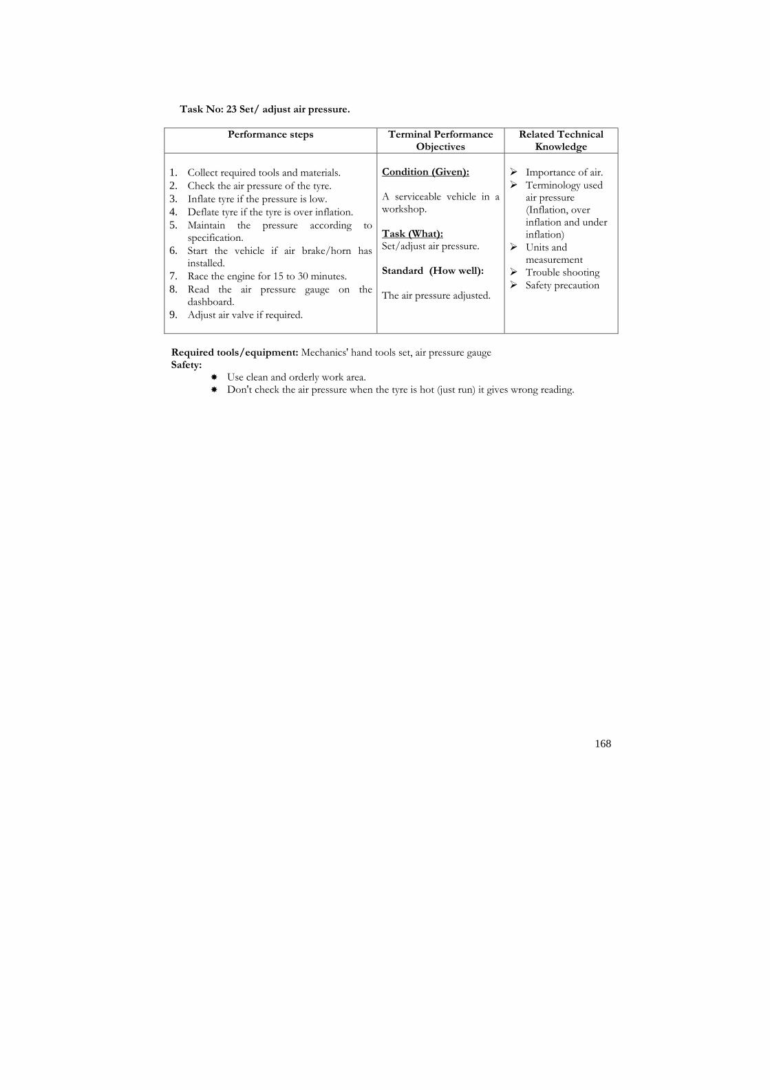
168
Task No: 23 Set/ adjust air pressure.
Performance steps Terminal Performance Objectives
Related Technical Knowledge
1. Collect required tools and materials.
2. Check the air pressure of the tyre.
3. Inflate tyre if the pressure is low. 4. Deflate tyre if the tyre is over inflation.
5. Maintain the pressure according to specification.
6. Start the vehicle if air brake/horn has installed.
7. Race the engine for 15 to 30 minutes.
8. Read the air pressure gauge on the dashboard.
9. Adjust air valve if required.
Condition (Given): A serviceable vehicle in a workshop. Task (What): Set/adjust air pressure. Standard (How well): The air pressure adjusted.
� Importance of air. � Terminology used
air pressure (Inflation, over inflation and under inflation)
� Units and measurement
� Trouble shooting � Safety precaution
Required tools/equipment: Mechanics' hand tools set, air pressure gauge Safety:
� Use clean and orderly work area. � Don't check the air pressure when the tyre is hot (just run) it gives wrong reading.

169
Task No: 24 Add/change steering oil.
Performance steps Terminal Performance Objectives
Related Technical Knowledge
1. Open the steering oil filler plug/cap. 2. Check the gear oil level. 3. Inspect the quality/properties of gear oil. 4. Add the specified grade of steering oil. 5. Maintain the oil level. 6. Remove the drain plug to drain the steering
oil if the oil has low viscous. 7. Drain the steering oil. 8. Tighten the drain plug 9. Refill the specified grade of steering oil. 10. Check the level of oil. 11. Add oil if level is low.
Condition (Given): A serviceable vehicle in a workshop. Task (What): Add/ change steering oil. Standard (How well): The steering oil changed within the specified level.
� Importance of
steering system. � Function and types
of steering gear box � Properties of
steering gear oil � Trouble shooting � Safety precaution
Required tools/equipment: Mechanics' hand tools set, funnel Safety:
� Observe safety practices while lifting and working under vehicle. � Never use broken seal or loose lubricant. � Use care when working with mechanic's hand tools. � Use clean and orderly work area.

170
Task No: 25 Adjust wheel hub play.
Performance steps Terminal Performance Objectives
Related Technical Knowledge
1. Lift the wheel that you want to adjust hub
play. 2. Remove the wheel. 3. Remove the wheel axle/hub cover. 4. Remove the lock nut and lock washer. 5. Remove the check nut and washer. 6. Remove the taper roller/wheel hub bearings. 7. Remove the axle shaft or spindle. 8. Clean all the components. 9. Fit the axle spindle to the housing. 10. Fit the wheel bearings. 11. Perform hub greasing. 12. Fit the thrust washer check nut. 13. Check the bearing preload. 14. Lock the bearing and axle shaft with lock
washer and lock nut. 15. Check the thrust play of wheel hub. 16. Add/remove thrust washer or shims to
increase/decrease the wheel axial play. 17. Repeat the step no. 15 and 16 until the play is
adjusted as specification. 18. Fit the wheel hub cover. 19. Fit the wheel. 20. Remove the jack.
Condition (Given): A serviceable vehicle in a workshop. Task (What): Adjust wheel hub play. Standard (How well): The wheel hub play adjusted according to specification provided.
� Importance and
identification of wheel hub play
� Terminology used wheel hub play
� Play adjusting process
� Trouble shooting � Safety precaution
Required tools/equipment: Mechanics' hand tools set, jack hydraulic or mechanical, wheel wrench,
bearing preload adjusting tool etc. Safety:
� Observe safety practices while lifting and working under vehicle. � Use safety practices while working with wheel to avoid injury. � Use safety precautions when working with mechanic's hand tools. � Use clean and orderly work area.

171
Module: 5
Auto Electrician
Description: This module is designed to equip trainees with the skills and knowledge on Auto Electricity as a specialized module related to the occupation. This module intends to provide skills and knowledge on repairing, replacing, changing and servicing of auto electrical systems. Objectives: After completion of this module the trainees will be able to: 1. Be familiar with auto electrical system 2. Repair and replace electrical system Duration: 40 hours (8 hours theory and 32 hours practical)
Tasks:
1. Charge battery. 2. Replace battery. 3. Replace ignition switch. 4. Repair/replace distributor. 5. Set ignition timing. 6. Repair/replace alternator. 7. Repair starter motor. 8. Replace/change lights/bulbs. 9. Change relay/switch in electrical system. 10. Repair wiper. 11. Troubleshoot electrical system. 12. Repair wiring. 13. Set head light beam 14. Service/ replace electrical accessories

172
Task No: 1 Charge battery.
Performance steps Terminal Performance Objectives
Related Technical Knowledge
1. Disconnect the battery terminal from vehicle.
2. Remove the battery and clean exterior. 3. Remove vent plugs from battery cell
covers. 4. Add distilled water if electrolyte level is
low. 5. Connect the battery to the charger. 6. Adjust/set minimum ampere of current. 7. Charge the battery until the specialized
gravity reads 1.280. 8. Insert rubber tube of hydrometer into
battery cell, squeeze and release rubber bulb so sufficient electrolyte is drawn into hydrometer to suspect float.
9. Take reading at eye level on float at point where it comes out of electrolyte.
10. Squeeze bulb to return electrolyte to cell. 11. Record reading. 12. Repeat for other cells. 13. Test specialized gravity of the battery in
every hour 14. Disconnect charger if the battery fully
charged. 15. Install the battery to the vehicle. 16. Reconnect the battery terminal.
Condition (Given): A discharged battery of a vehicle. Task (What): Charge battery. Standard (How well): The battery charged as per manufacturer's specifications and procedure. The specialized gravity of the charged battery must be more than 1.280 and above 12 volts.
� Interpretation of
manufacturer's manual
� Importance, identification and types of electrical circuit (series, shunt/parallel and combined circuit.
� Working principle and function of battery
� Technical terms associate with battery
� Battery charging and testing process
� Trouble shooting � Safety precautions
Required tools/equipment: Mechanic's hand tools set, manufacturer's service manual, volt-ohmmeter (multimeter), hydrometer, battery charger, terminal clamp, Safety:
� Follow correct electrical safety procedures to avoid short circuit and injury. � Use care when handling acid or working on battery to avoid short circuit and eye injury. � Use care when working with mechanic's tools to avoid injury. � Maintain clean and orderly work area.

173
Task No: 2 Replace battery.
Performance steps Terminal Performance Objectives
Related Technical Knowledge
1. Disconnect both battery terminals, always do negative terminal first for safety practice.
2. Remove bracket, mounting clamp or cover to gain access to the battery.
3. Clean battery external and top cover. 4. Lift the battery from chassis/body.
5. Dispose the old battery properly.
6. Check the electrolyte level of new battery. 7. Add sulphuric acid or distilled water as per
manufacturer's instructions and procedures.
8. Plug the vent plugs properly. 9. Replace the new battery.
10. Clamp or secure the battery in battery tray or case.
11. Connect the battery terminals, always connect positive terminal first.
12. Use petroleum jelly or Vaseline or white grease to the terminal post.
13. Start the vehicle and check the battery performance.
Condition (Given): A faulty battery of a vehicle. Task (What): Replace battery. Standard (How well): The battery repaired as per manufacturer's specifications and procedure.
� Interpretation of
manufacturer's manual
� Technical terms associate with battery
� Battery testing process
� Operating principles and functions of battery
� Trouble shooting
Required tools/equipment: Mechanic's hand tools set, manufacturer's service manual, volt-ohmmeter (multimeter), test lamp Safety:
� Follow correct electrical safety procedures to avoid short circuit and injury. � Use care when working with mechanic's tools to avoid injury.
Maintain clean and orderly work area.

174
Task No: 3 Replace ignition switch.
Performance steps Terminal Performance Objectives
Related Technical Knowledge
1. Disconnect the negative battery terminal.
2. Determine the wiring circuit as per manufacturer.
3. Disconnect the electrical connectors after marking them with tape for identification when reinstalling.
4. Remove components as necessary to gain access to the ignition switch as per manufacturer's procedure and specifications.
5. Clean wiring harness connectors.
6. Test the ignition switch as manufacturer's procedures.
7. Replace new ignition switch.
8. Connect switch wires to their original location.
9. Replace all components that were removed to gain access to ignition switch.
10. Connect battery negative terminal.
11. Start the engine and check the switch operation.
Condition (Given): A faulty ignition switch of a vehicle. Task (What): Replace ignition switch Standard (How well): The ignition switch replaced as per manufacturer's specifications and procedure. The switch must be performed all function correctly.
� Interpretation of
manufacturer's manual
� Electrical wiring diagram/symbol.
� Technical terms associate with ignition switch
� Methods of testing switch
� Operating principles, functions and types of ignition switch
� Trouble shooting
Required tools/equipment: Mechanic's hand tools set, manufacturer's service manual, volt-ohmmeter (multimeter), test lamp, or special equipment as required by manufacturer. Safety:
� Follow correct electrical safety procedures to avoid short circuit and injury. � Use care when working on ignition switch to avoid high voltage shock & bodily injury. � Use care when working with mechanic's tools to avoid injury. � Maintain clean and orderly work area.

175
Task No: 4 Repair/replace distributor.
Performance steps Terminal Performance Objectives
Related Technical Knowledge
1. Refer to manufacturer's service manual for specifications and procedures.
2. Disconnect primary and secondary ignition wires from distributor.
3. Check and mark the position of rotor. 4. Remove distributor cap off.
5. Loosen mounting bolts and remove distributor.
6. Remove breaker arm and springs.
7. Remove stationary breaker point bracket.
8. Clean then lubricate cam with distributor cam lubricant.
9. Remove and replace condenser. 10. Install new points in reverse order of the
procedure used to disassemble.
11. Set breaker points using feeler gauge check with dwell meter.
12. Disassemble per manufacturer's instructions. 13. Repair or replace and test all parts needed to
bring distributor to manufacturer's specifications.
14. Reassemble per manufacturer's specifications.
15. Install distributor. The rotor must be in the same position as it was removed before.
16. Reconnect primary and secondary ignition wires.
17. Set ignition timing using timing light. 18. Test completed distributor per
manufacturer's specifications.
Condition (Given): A faulty ignition system of a vehicle. Task (What): Rebuild distributor. Standard (How well): The faulty components identified and repaired or replaced and distributor must conform to manufacturer's specifications.
� Interpretation of
manufacturer's manual.
� Ignition system circuit diagram.
� Technical terms associate with ignition systems.
� Working principles, functions and types of distributor
� Distributor testing process
� Trouble shooting � Safety precautions
Required tools/equipment: Mechanic's hand tools set, manufacturer's service manual, test lamp, timing light or special equipment as required by manufacturer. Safety:
� Follow correct electrical safety procedures to avoid short circuit and injury. � Use care when working on ignition system to avoid high voltage shock & bodily injury. � Use care when working with mechanic's tools to avoid injury. � Maintain clean and orderly work area.
Task No: 5 Set ignition timing.

176
Performance steps Terminal Performance Objectives
Related Technical Knowledge
1. Check operator's manual for specifications.
2. Locate timing marks on flywheel or fan pulley.
3. Turn engine until cam opens breaker points to widest position.
4. Check contact points for proper spacing/gap using a feeler gauge.
5. Adjust contact points for proper alignment and gap or spacing.
6. Loosen lock screw on breaker plate bracket if adjustment is necessary.
7. Recheck gap between points and wipe clean.
8. Check anti make final adjustments using the dwell meter.
9. Connect timing light as recommended by manufacturer.
10. Determine from operator's manual what timing mark to use with light, and correct engine RPM.
11. Chalk the timing mark so it is easily seen. 12. Start engine and run at speed recommended
in service manual. 13. Direct timing light at markings on flywheel
or on crank pulley.
14. Loosen clamps that hold distributor. 15. Turn distributor body slightly until timing
mark is opposite the pointer. 16. Tighten the distributor.
17. Recheck the timing after tightening.
18. Remove timing light.
19. Replace cover over timing hole or inspection plate if removed.
Condition (Given): A faulty ignition system of a vehicle. Task (What): Set ignition timing. Standard (How well): The ignition system set as per manufacturer's specifications and procedure. The engine must be free from noise, black smoke and have higher performance.
� Interpretation of
manufacturer's manual
� Ignition circuit diagram.
� Technical terms associate with ignition systems.
� Function of main parts of the ignition system
� Ignition timing setting and testing process.
� Causes, effects, of incorrect ignition timing
� Trouble shooting � Safety precautions
Required tools/equipment: Mechanic's hand tools set, manufacturer's service manual, feeler gauge, dwell meter, timing light, test lamp, or special equipment as required by manufacturer. Safety:
� Follow correct electrical safety procedures to avoid short circuit and injury. � Use care when working on ignition system to avoid high voltage shock & bodily injury. � Use care when working with mechanic's tools to avoid injury. � Maintain clean and orderly work area.

177
Task No: 6 Repair/replace alternator.
Performance steps Terminal Performance Objectives
Related Technical Knowledge
1. Consult service manual. 2. Remove battery ground terminal.
3. Disconnect connector/wires to alternator
4. Remove alternator.
5. Clean exterior of alternator.
6. Remove through bolts. 7. Examine the position of stator output
leads relative to alternator fixing lugs and lift stator from drive end bracket.
8. Clamp rotor and unscrew shaft nut.
9. Remove pulley and fan. 10. Unscrew bearing retainer plate fixing
screw and remove bearing and retainer. 11. Remove suppression capacitor fixing
screw and remove capacitor.
12. Unscrew rectifier-fixing screw and remove baffle plate.
13. Remove slip ring end bearing.
14. Remove slip ring end bracket assembly and separate stator and rectifier by desoldering the stator connecting lead between field connector plates to brush box terminal.
15. Disconnect regulator leads, unscrew and remove regulator.
16. Remove brush box by unscrewing the screw from slip ring end bracket and lift off brush box assembly.
17. Clean all parts carefully.
18. Check parts for wearness and replace if necessary.
19. Reassemble the alternator components as reversal of the dismantling procedure.
20. Install the alternator.
21. Reconnect wires to alternator and regulator.
22. Reconnect battery terminal.
23. Test the alternator performance. 24. Test on bench with proper power
supply.
Condition (Given): A faulty alternator. Task (What): Repair/replace alternator. Standard (How well): The alternator repaired and output of the alternator must be as per manufacturer's specifications.
� Interpretation of
manufacturer's manual.
� Charging circuit diagram.
� Technical terms associate with charging systems
� Alternator testing Process
� Working principles, functions and types of alternator
� Trouble shooting � Safety precautions
Safety:
� Follow correct electrical safety procedures to avoid short circuit and injury. � Use care when working with mechanic's tools to avoid injury.

178
Task No: 7 Repair starter motor.
Performance steps Terminal Performance Objectives
Related Technical Knowledge
1. Consult service manual.
2. Remove battery ground terminal.
3. Remove wires to starter motor. 4. Remove starter bolts and starter motor.
5. Clean exterior of starter motor.
6. Remove cover over brushes. 7. Remove the solenoid from the starter.
8. Remove all brushes from retainers.
9. Remove commutator end plate. 10. Remove through bolts.
11. Remove drive end of housing.
12. Remove retaining ring and old drive. 13. Remove armature.
14. Inspect commutator and retainers for damage.
15. Remove bushing with appropriate puller or driver.
16. Inspect housing and shaft for wear.
17. Install new bearing and shaft.
18. Lubricate the bushings and starter drive shaft with specified lubricant.
19. Install new drive, retaining ring and brushes.
20. Pull back the brush springs with hook and insert brushes into their holders.
21. Slide in end plate.
22. Cover brushes. 23. Install the new solenoid on the starter
motor. 24. Reassemble the starter motor.
25. Install starter motor.
26. Tighten starter bolts. 27. Reconnect wires to starter motor.
28. Reconnect battery negative terminal.
29. Check operation with battery. 30. Test on bench with proper power supply.
Condition (Given): A faulty starter motor of a vehicle. Task (What): Repair starter motor. Standard (How well): The starter motor repaired as per manufacturer's specifications and procedure. Wires must be properly routed and secured.
� Interpretation of
manufacturer's manual
� Starting system circuit diagram
� Technical terms associate with starting systems
� Starter motor testing process
� Working principles, functions and types of starter motor
� Trouble shooting � Safety precautions
Required tools/equipment: Mechanic's hand tools set, manufacturer's service manual, volt-ohmmeter (multimeter), test lamp, or special equipment as required by manufacturer. Safety:
� Follow correct electrical safety procedures to avoid short circuit and injury. � Use care when working with mechanic's tools to avoid injury. � Maintain clean and orderly work area.
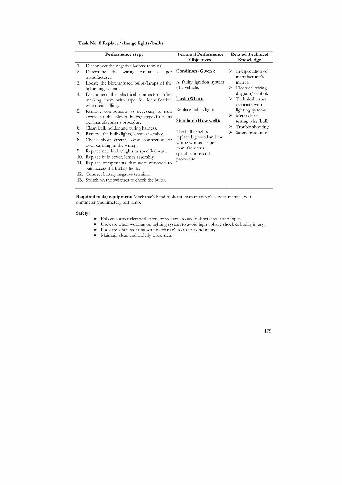
179
Task No: 8 Replace/change lights/bulbs.
Performance steps Terminal Performance Objectives
Related Technical Knowledge
1. Disconnect the negative battery terminal.
2. Determine the wiring circuit as per manufacturer.
3. Locate the blown/fused bulbs/lamps of the lightening system.
4. Disconnect the electrical connectors after marking them with tape for identification when reinstalling.
5. Remove components as necessary to gain access to the blown bulbs/lamps/fuses as per manufacturer's procedure.
6. Clean bulb holder and wiring harness. 7. Remove the bulb/lights/lenses assembly.
8. Check short circuit, loose connection or poor earthing in the wiring.
9. Replace new bulbs/lights as specified watt.
10. Replace bulb cover, lenses assembly.
11. Replace components that were removed to gain access the bulbs/ lights.
12. Connect battery negative terminal. 13. Switch on the switches to check the bulbs.
Condition (Given): A faulty ignition system of a vehicle. Task (What): Replace bulbs/lights Standard (How well): The bulbs/lights replaced, glowed and the wiring worked as per manufacturer's specifications and procedure.
� Interpretation of
manufacturer's manual
� Electrical wiring diagram/symbol.
� Technical terms associate with lighting systems.
� Methods of testing wire/bulb
� Trouble shooting � Safety precaution
Required tools/equipment: Mechanic's hand tools set, manufacturer's service manual, volt-ohmmeter (multimeter), test lamp. Safety:
� Follow correct electrical safety procedures to avoid short circuit and injury. � Use care when working on lighting system to avoid high voltage shock & bodily injury. � Use care when working with mechanic's tools to avoid injury. � Maintain clean and orderly work area.
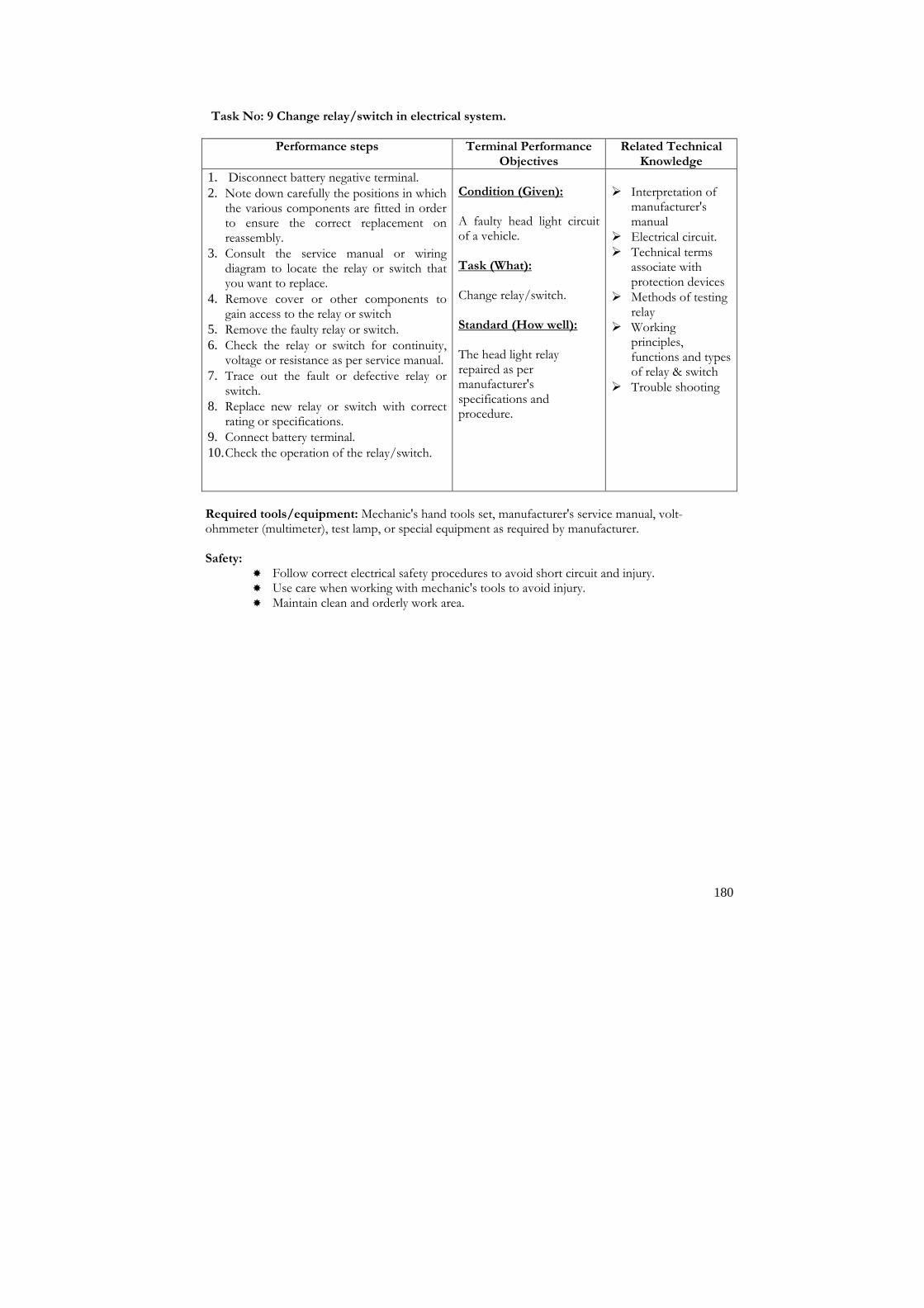
180
Task No: 9 Change relay/switch in electrical system.
Performance steps Terminal Performance Objectives
Related Technical Knowledge
1. Disconnect battery negative terminal.
2. Note down carefully the positions in which the various components are fitted in order to ensure the correct replacement on reassembly.
3. Consult the service manual or wiring diagram to locate the relay or switch that you want to replace.
4. Remove cover or other components to gain access to the relay or switch
5. Remove the faulty relay or switch.
6. Check the relay or switch for continuity, voltage or resistance as per service manual.
7. Trace out the fault or defective relay or switch.
8. Replace new relay or switch with correct rating or specifications.
9. Connect battery terminal.
10. Check the operation of the relay/switch.
Condition (Given): A faulty head light circuit of a vehicle. Task (What): Change relay/switch. Standard (How well): The head light relay repaired as per manufacturer's specifications and procedure.
� Interpretation of
manufacturer's manual
� Electrical circuit. � Technical terms
associate with protection devices
� Methods of testing relay
� Working principles, functions and types of relay & switch
� Trouble shooting
Required tools/equipment: Mechanic's hand tools set, manufacturer's service manual, volt-ohmmeter (multimeter), test lamp, or special equipment as required by manufacturer. Safety:
� Follow correct electrical safety procedures to avoid short circuit and injury. � Use care when working with mechanic's tools to avoid injury. � Maintain clean and orderly work area.

181
Task No: 10 Repair wiper.
Performance steps Terminal Performance Objectives
Related Technical Knowledge
1. Disconnect battery terminal and connector to wiper motor.
2. Examine the positions in which the various components are fitted in order to ensure the correct replacement on reassembly.
3. Mark the gearbox cover adjacent to the arrowhead on the limit switch cover. This will allow the original setting of the limit switch to be determined on reassembly.
4. Unscrew the cover plate. Please note down the position of capacitor, cable clip and earth tag.
5. Unscrew the main gear wheel lock nut and remove the gear wheel and driving plate.
6. Tap on the nut before removing gear wheel to part the gearwheel from the shaft.
7. Withdrawn the shaft and link assembly from underneath the gearbox.
8. Remove the rotary link from the gearbox. Please ensure the dished washer is not missed.
9. Remove the final gear.
10. Remove the worm wheel.
11. Remove the two yoke fixing through bolts and spring washers.
12. Withdraw the yoke assembly from gearbox.
13. Use a mallet and gently tap the gearbox casting to remove the yoke.
14. Remove the brush gear fixing screws and limit switch complete with connecting cables and brush gear plate along with armature.
15. Remove the armature from the brush plate.
16. Ensure to hold back all the three brushes while departing armature from the brush plate assembly.
17. Clean all the parts thoroughly.
18. Fix the brush plate assembly to the casting before armature assembly.
19. Reassemble the wiper motor in the reverse order to that of dismantling.
20. Install the wiper motor and connect wiring
21. Check the operation of the wiper motor.
Condition (Given): A faulty wiper system of a vehicle. Task (What): Repair wiper. Standard (How well): The wiper repaired as per manufacturer's specifications and procedure. The wiper run free from noise and vibration.
� Interpretation of
manufacturer's manual.
� Wiper system wiring diagram.
� Technical terms associate with wiper
� Operating principles, function and types of wiper.
� Wiper repairing/testing process
� Trouble shooting � Safety precautions
Safety: � Follow correct electrical safety procedures to avoid short circuit and injury. � Use care when working with mechanic's tools to avoid injury.

182
Task No: 11 Troubleshoot electrical system.
Performance steps Terminal Performance Objectives
Related Technical Knowledge
1. Consult manual for varying procedures. 2. Ask the driver for symptoms. 3. Inspect electrical system visually. 4. Begin at battery and trace system. 5. Record problems, as they are located. 6. Disconnect any component that may
damage the system. 7. Replace the faulty components. 8. Check the continuity and resistance of the
cable/wire of the system. 9. Replace wire/cable if necessary. 10. Check poor/ loose connections and
earthing. 11. Perform services as necessary. 12. Recheck the electrical system to conform.
Condition (Given): A faulty electrical system of a vehicle. Task (What): Troubleshoot given electrical system. Standard (How well): The system checked completely and all troubles recorded.
� Interpretation of
manufacturer's manual
� Electrical wiring diagram/symbol
� Technical terms associate with electrical systems.
� Causes and effect of malfunctioning electrical system
� Trouble shooting � Safety precautions
Required tools/equipment: Mechanic's hand tools set, manufacturer's service manual, volt-ohmmeter (multimeter), test lamp, or special equipment as required by manufacturer. Safety:
� Follow correct electrical safety procedures to avoid short circuit and injury. � Use care when working with mechanic's tools to avoid injury. � Maintain clean and orderly work area.

183
Task No: 12 Repair wiring.
Performance steps Terminal Performance Objectives
Related Technical Knowledge
1. Locate the wiring harness, switches, and fuses, of the electrical system to be repaired.
2. Remove components as necessary to gain access to the wiring harness as per manufacturer's procedure and specifications.
3. Clean wiring harness connectors with electronic connector cleaner.
4. Check service manual for test procedures.
5. Make voltage and resistance readings with ignition key on or off as required.
6. Compare reading with service manual specifications.
7. Check all connector for open circuits.
8. Check all wiring for bare spots breaks or shorts.
9. Reconnect all connectors as per manufacturer's procedures and specifications.
10. Record test results on work order.
Condition (Given): A faulty electrical system of a vehicle. Task (What): Repair wiring. Standard (How well): Any malfunctions or defects in the electrical system wiring harness detected.
� Interpretation of
manufacturer's manual, wiring diagram/symbol and results of test equipment
� Basic electricity. � Importance, types
and parts of electrical system.
� Technical terms associate with electrical system.
� Electrical circuit testing procedure.
� Operating principles and functions of electrical systems
� Trouble shooting
Required tools/equipment: Mechanic's hand tools set, manufacturer's service manual, volt-ohmmeter (multimeter), test lamp, or special equipment as required by manufacturer, electronic connector cleaner. Safety:
� Follow correct electrical safety procedures to avoid short circuit and injury. � Use care when working with mechanic's tools to avoid injury. � Maintain clean and orderly work area.

184
Task No: 13 Set head light beam.
Performance steps Terminal Performance Objectives
Related Technical Knowledge
1. Adjust air pressure of all tyres as per the manufacturers’ recommendation
2. Move vehicle up and down by hand to settle its attitude
3. Move it over a flat surface 4. Set vertical beam alignment by means of the
screw provided in head light 5. (Set the head light in such a way that the main
beam axis falls on a spot not above the height of head light and not below a height equal to a fifth (1/5) of the head light height.)
6. Set horizontal beam alignment by using screw provided in head light
Condition (Given): A serviceable vehicle Task (What): Set head light beam Standard (How well): The head light vertical beam to be set in such a way that the main beam axis falls on a spot not above the height of head light and not below a height equal to a fifth (1/5) of the head light height. Horizontal beam set as per the specification
� Interpretation of
manufacturer's manual
� Electrical wiring diagram/symbol
� Technical terms associate with lighting systems
� Methods of testing wire/bulb
� Trouble shooting � Function of head
light � Safety precaution
Required tools/equipment: Mechanic's hand tools set, manufacturer's service manual. Safety:
� Follow correct electrical safety procedures to avoid short circuit and injury. � Use care when working on lighting system to avoid high voltage shock & bodily injury. � Use care when working with mechanic's tools to avoid injury. � Maintain clean and orderly work area.

185
Task No: 14 Service/ Replace Electrical Accessories.
Performance steps Terminal Performance Objectives
Related Technical Knowledge
Windshield wiper and water spray pump 1. Check/ Change wiper fuse 2. Check/ repair wiper motor 3. Check/ repair wiper control switch 4. Check/ repair wiring or ground 5. Check/ replace water spray pump 6. Check/ repair washer hose or nozzle
for clogging Electrical horn.
7. Check/ change horn fuse. 8. Check/ change horn 9. Check/ repair wiring
Electrical clock 10. Check/ change clock
Electrical fuel pump 11. Check repair fuel pressure after 3
second of ignition on position 12. Check/ repair the fuel pump relay 13. Check/ change fuel pump.
Defrosters 14. Check repair defogger switch 15. Check replace defogger heat wire 16. Check repair wiring or grounding
Radiator cooling fan 17. Check replace fan relay 18. Check cooling fan 19. Check repair wiring or grounding
Others 20. Check replace fuse/ relay 21. Check the accessories 22. Check repair wiring or grounding
Condition (Given): A faulty electrical system of a vehicle. Task (What): Check and repair electrical accessories Standard (How well): The system checked completely and all troubles recorded.
� Interpretation of
manufacturer's manual
� Principal of working of electrical accessories
� Function of fuse and relay
� Electrical wiring diagram/symbol.
� Technical terms associate with electrical systems
� Causes and effect of malfunctioning electrical system.
� Trouble shooting � Safety precautions
Required tools/equipment: Mechanic's hand tools set, manufacturer's service manual, volt-ohmmeter (multimeter), test lamp, or special equipment as required by manufacturer. Safety:
� Follow correct electrical safety procedures to avoid short circuit and injury. � Use care when working with mechanic's tools to avoid injury. � Maintain clean and orderly work area.