auto detection and configuration of prrt coding relays in
TRANSCRIPT
Bachelor Thesis
Auto Detection andConfiguration of PRRT CodingRelays in OpenFlow Networks
Frank WaßmuthAuthor
Dipl.-Ing. Michael KarlAdvisor
Prof. Dr.-Ing. Thorsten HerfetSupervisor
Prof. Dr. Dietrich KlakowReviewer
Saarland University
Faculty of Natural Sciences and Technology I
Department of Computer Science

Bachelorarbeit
UNIVERSITÄT DES SAARLANDES
Lehrstuhl für Nachrichtentechnik
FR Informatik
Prof. Dr. Th. Herfet
Universität des Saarlandes Campus Saarbrücken C6 3, 10. OG 66123 Saarbrücken
Telefon (0681) 302-6541 Telefax (0681) 302-6542
www.nt.uni-saarland.de
Bachelor Thesis Frank Waßmuth
Mat. Nr.: 2523982
Auto detection and configuration
of PRRT Coding Relays in OpenFlow Networks
The Internet faces the shift from text based transmissions to high data rate transfer of high quality audiovisual content. More than 20% of the global Internet traffic is produced by video streams transmitted by HTTP. According to some forecasts, in the next decade more than 80%-90% of the global Internet traffic is caused by (Live) video transmissions. At the same time the requirements of modern transport and routing protocols are changing. Whereas a complete error-free transmission was the most important characteristic of a transmission up to now, the focus has changed to also consider timing constraints and application specific residual error rate toleranc-es. Both are crucial demands of audiovisual transmissions. Thus, future transmission protocols have to provide strong capabilities to adapt their behavior and performance to both, the underlying network quality and the transmitted content.
A major challenge during the research of these new transport protocols is that test-ing is a hard process since real-world networks are required to obtain an efficient view of the protocol performance. On the other hand productive networks should not suffer from these experimental protocols.
Therefore, the OpenFlow Project1 provides researchers a possibility to run experi-mental protocols in productive networks.
The Telecommunications Lab developed a transport protocol that is able to provide a Predictable Reliable Real Time (PRRT) 2 transport of multimedia content. In addition, the Telecommunications Lab developed a OpenFlow/NOX controller module to add support for PRRT transmission to the OpenFlow environment.
The subject of this bachelor thesis is to develop an auto detection mechanism to find and configure PRRT coding relays in an OpenFlow enabled network. In particular, the tasks to be solved are the following:
Development of an in-band auto detection mechanism for PRRT coding re-lays for the NOX controller.
Design of an in-band coding relay configuration and monitoring approach.
Provide a corresponding implementation and evaluation.
Tutor: Supervisor: Dipl.-Ing. Michael Karl
Prof. Dr.-Ing.Thorsten Herfet
1 http://www.openflow.org
2 http://www.nt.uni-saarland.de/projects/prrt/
—

Eidesstattliche Erklarung
Ich erklare hiermit an Eides Statt, dass ich die vorliegende Arbeit selbstandig verfasst und keineanderen als die angegebenen Quellen und Hilfsmittel verwendet habe.
Statement in Lieu of an Oath
I hereby confirm that I have written this thesis on my own and that I have not used any othermedia or materials than the ones referred to in this thesis
Einverstandniserklarung
Ich bin damit einverstanden, dass meine (bestandene) Arbeit in beiden Versionen in die Biblio-thek der Informatik aufgenommen und damit veroffentlicht wird.
Declaration of Consent
I agree to make both versions of my thesis (with a passing grade) accessible to the public byhaving them added to the library of the Computer Science Department.
Saarbrucken, den
Frank Waßmuth
Abstract
Networks are experiencing a paradigm shift from textual data to high data rate multimedia traf-fic. Traditional network protocols can generally not keep up with this change. Software DefinedNetworking frameworks such as OpenFlow try to enable network engineers to more easily de-velop new protocol architectures and to deliver superior network performance. These frameworksprovide a standardized way to communicate with network devices without requiring vendors tofully disclose their proprietary platforms. While OpenFlow provides a simple way to interfacewith core network elements such as routers or switches, it does not offer standardized interfacesfor a full class of supporting network devices such as coding relays or data stores. By propos-ing an augmented version of the Link Layer Discovery Protocol (LLDP) and an accompanyingreference implementation this thesis provides a way to monitor and manage such devices fromwithin the OpenFlow framework without requiring the additional complexity usually introducedby traditional management protocols.
Contents
1 Introduction 6
2 OpenFlow 62.1 History . . . . . . . . . . . . . . . . . . . . . . . . . . . . . . . . . . . . . . . . . 62.2 Architecture . . . . . . . . . . . . . . . . . . . . . . . . . . . . . . . . . . . . . . . 72.3 Tables . . . . . . . . . . . . . . . . . . . . . . . . . . . . . . . . . . . . . . . . . . 8
2.3.1 Flow Table . . . . . . . . . . . . . . . . . . . . . . . . . . . . . . . . . . . 82.3.2 Group Table . . . . . . . . . . . . . . . . . . . . . . . . . . . . . . . . . . 92.3.3 Meter Table . . . . . . . . . . . . . . . . . . . . . . . . . . . . . . . . . . . 10
2.4 OpenFlow Channel . . . . . . . . . . . . . . . . . . . . . . . . . . . . . . . . . . . 102.4.1 Controller-to-Switch . . . . . . . . . . . . . . . . . . . . . . . . . . . . . . 112.4.2 Asynchronous . . . . . . . . . . . . . . . . . . . . . . . . . . . . . . . . . . 112.4.3 Synchronous . . . . . . . . . . . . . . . . . . . . . . . . . . . . . . . . . . 12
2.5 Switches . . . . . . . . . . . . . . . . . . . . . . . . . . . . . . . . . . . . . . . . . 122.5.1 Switch Types . . . . . . . . . . . . . . . . . . . . . . . . . . . . . . . . . . 122.5.2 Port Types . . . . . . . . . . . . . . . . . . . . . . . . . . . . . . . . . . . 12
2.6 Controller . . . . . . . . . . . . . . . . . . . . . . . . . . . . . . . . . . . . . . . . 13
3 Predictably Reliable Real-Time Transport (PRRT) 15
4 Motivation 16
5 LLDP (IEEE 802.3ab) 175.1 Packet Structure . . . . . . . . . . . . . . . . . . . . . . . . . . . . . . . . . . . . 175.2 Type-Length-Values . . . . . . . . . . . . . . . . . . . . . . . . . . . . . . . . . . 185.3 Organizationally Specific TLVs . . . . . . . . . . . . . . . . . . . . . . . . . . . . 21
6 Augmented LLDP 216.1 Node Discovery and Supervision . . . . . . . . . . . . . . . . . . . . . . . . . . . 226.2 Node Configuration . . . . . . . . . . . . . . . . . . . . . . . . . . . . . . . . . . . 226.3 Technical Specification . . . . . . . . . . . . . . . . . . . . . . . . . . . . . . . . . 236.4 Implementation . . . . . . . . . . . . . . . . . . . . . . . . . . . . . . . . . . . . . 24
6.4.1 dpkt . . . . . . . . . . . . . . . . . . . . . . . . . . . . . . . . . . . . . . . 256.4.2 pypcap . . . . . . . . . . . . . . . . . . . . . . . . . . . . . . . . . . . . . 256.4.3 ALLDPd . . . . . . . . . . . . . . . . . . . . . . . . . . . . . . . . . . . . 256.4.4 PRRT Plugin for ALLDPd . . . . . . . . . . . . . . . . . . . . . . . . . . 296.4.5 Controller Helper Classes . . . . . . . . . . . . . . . . . . . . . . . . . . . 29
6.5 Usage Examples . . . . . . . . . . . . . . . . . . . . . . . . . . . . . . . . . . . . 316.5.1 ALLDPd . . . . . . . . . . . . . . . . . . . . . . . . . . . . . . . . . . . . 316.5.2 ALLDPCollection . . . . . . . . . . . . . . . . . . . . . . . . . . . . . . . 326.5.3 ALLDPWrapper . . . . . . . . . . . . . . . . . . . . . . . . . . . . . . . . 326.5.4 ALLDP dpkt classes . . . . . . . . . . . . . . . . . . . . . . . . . . . . . . 33
7 Evaluation 35
8 Conclusion 37
1 Introduction
Data networks, be it in business, education or at home, have become part of the critical in-frastructure. Connections to billions of devices increase communication efficiency and provideopportunities for businesses, private entities and researchers alike, which, over the years, led toan enormous installed base of equipment.
Most protocols found in today’s networks have been designed several decades ago. While at thetime most content consisted of text, today’s networks - especially the Internet - are experiencinga paradigm shift away from textual content to high data rate audio and video content. Thischange requires more suitable (i.e. efficient) protocols to make the most of the available networkbandwidth. To develop such protocols researchers need to access networking hardware in a non-standard way, however vendors providing specialized networking hardware are cautious to shareinternals of their products, eventually opening their systems to potential competitors. Sincecommodity hardware (e.g. PCs / Servers) does neither provide the port density nor the packet-processing capacity needed to implement meaningful experiments. This makes it hard (if next toimpossible) for researchers to conduct any experiments in sufficiently realistic settings. Due tothe criticality of the infrastructure network operators are also generally reluctant to experimentwith production traffic.
Software Defined Networks (SDNs) are trying to alleviate the barrier-to-entry for researchers,by providing a programmable platform to test and develop new network protocols or non-standardized means of communication. In addition to enabling researchers to test and designprotocols more suitable for current communication demands, SDNs can also be used to buildand manage networks more efficiently, thus enabling network designs which are far more resilientto node/switch failure or which are scalable way beyond traditional network architectures (hy-perscale networks).
2 OpenFlow
OpenFlow is the leading SDN architecture available at the time of this writing. It offers re-searchers a way to experiment with network traffic without requiring vendors to fully open theirproduct specifications by defining interfaces to a programmable controller. By introducing astandardized protocol OpenFlow effectively masks the underlying switch architecture from de-velopers, therefore protocols and management systems defined using OpenFlow are more or lessvendor independent. At the same time OpenFlow provides mechanisms to allow experimentaltraffic to coexist with (i.e. not interfere with) production traffic, such as segmentation of net-works based on VLANs, source/destination ports/networks, protocols or any other arbitrarycriteria.
At the time of this writing the current OpenFlow version is 1.3 ([3], [2]). In the followingchapters this thesis focuses on the most recent protocol version and outlines differences to theversion used by the Telecommunications Lab as needed.
2.1 History
The OpenFlow standard [3] was first published by Stanford University in 2008, but is currentlymaintained by the Open Networking Foundation1.
1http://www.opennetworking.org
6
The Open Networking Foundation, which was founded in 2011, is a non-profit consortiumdedicated to the transformation of networking through the development and standardization ofSoftware Defined Networking, which brings direct software programmability to networks. TheONF includes 70+ members, the most prominent being Deutsche Telekom, Facebook, Googleand Microsoft, but also many global players from the networking community such as Broadcom,Brocade, Cisco, HP, Intel and Netgear.
2.2 Architecture
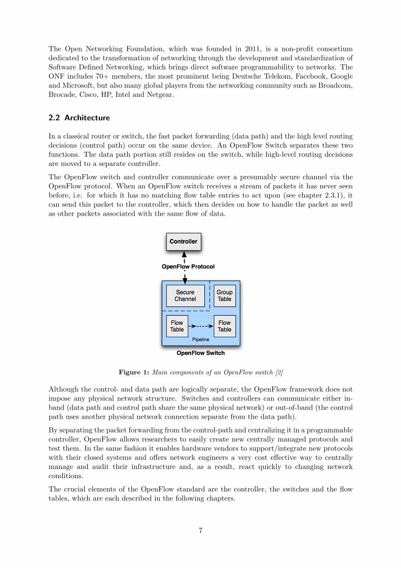
In a classical router or switch, the fast packet forwarding (data path) and the high level routingdecisions (control path) occur on the same device. An OpenFlow Switch separates these twofunctions. The data path portion still resides on the switch, while high-level routing decisionsare moved to a separate controller.
The OpenFlow switch and controller communicate over a presumably secure channel via theOpenFlow protocol. When an OpenFlow switch receives a stream of packets it has never seenbefore, i.e. for which it has no matching flow table entries to act upon (see chapter 2.3.1), itcan send this packet to the controller, which then decides on how to handle the packet as wellas other packets associated with the same flow of data.
Figure 1: Main components of an OpenFlow switch [2]
Although the control- and data path are logically separate, the OpenFlow framework does notimpose any physical network structure. Switches and controllers can communicate either in-band (data path and control path share the same physical network) or out-of-band (the controlpath uses another physical network connection separate from the data path).
By separating the packet forwarding from the control-path and centralizing it in a programmablecontroller, OpenFlow allows researchers to easily create new centrally managed protocols andtest them. In the same fashion it enables hardware vendors to support/integrate new protocolswith their closed systems and offers network engineers a very cost effective way to centrallymanage and audit their infrastructure and, as a result, react quickly to changing networkconditions.
The crucial elements of the OpenFlow standard are the controller, the switches and the flowtables, which are each described in the following chapters.
7
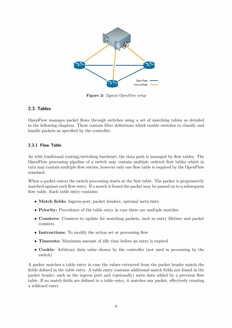
Figure 2: Typical OpenFlow setup
2.3 Tables
OpenFlow manages packet flows through switches using a set of matching tables as detailedin the following chapters. These contain filter definitions which enable switches to classify andhandle packets as specified by the controller.
2.3.1 Flow Table
As with traditional routing/switching hardware, the data path is managed by flow tables. TheOpenFlow processing pipeline of a switch may contain multiple ordered flow tables which inturn may contain multiple flow entries, however only one flow table is required by the OpenFlowstandard.
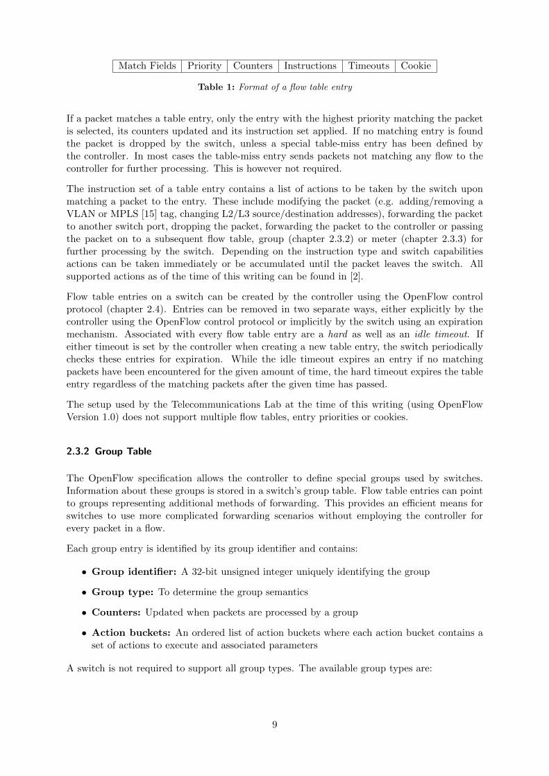
When a packet enters the switch processing starts at the first table. The packet is progressivelymatched against each flow entry. If a match is found the packet may be passed on to a subsequentflow table. Each table entry contains:
• Match fields: Ingress-port, packet headers, optional meta data
• Priority: Precedence of the table entry in case there are multiple matches
• Counters: Counters to update for matching packets, such as entry lifetime and packetcounters
• Instructions: To modify the action set or processing flow
• Timeouts: Maximum amount of idle time before an entry is expired
• Cookie: Arbitrary data value chosen by the controller (not used in processing by theswitch)
A packet matches a table entry in case the values extracted from the packet header match thefields defined in the table entry. A table entry contains additional match fields not found in thepacket header, such as the ingress port and (optionally) meta data added by a previous flowtable. If no match fields are defined in a table entry, it matches any packet, effectively creatinga wildcard entry.
8
Match Fields Priority Counters Instructions Timeouts Cookie
Table 1: Format of a flow table entry
If a packet matches a table entry, only the entry with the highest priority matching the packetis selected, its counters updated and its instruction set applied. If no matching entry is foundthe packet is dropped by the switch, unless a special table-miss entry has been defined bythe controller. In most cases the table-miss entry sends packets not matching any flow to thecontroller for further processing. This is however not required.
The instruction set of a table entry contains a list of actions to be taken by the switch uponmatching a packet to the entry. These include modifying the packet (e.g. adding/removing aVLAN or MPLS [15] tag, changing L2/L3 source/destination addresses), forwarding the packetto another switch port, dropping the packet, forwarding the packet to the controller or passingthe packet on to a subsequent flow table, group (chapter 2.3.2) or meter (chapter 2.3.3) forfurther processing by the switch. Depending on the instruction type and switch capabilitiesactions can be taken immediately or be accumulated until the packet leaves the switch. Allsupported actions as of the time of this writing can be found in [2].
Flow table entries on a switch can be created by the controller using the OpenFlow controlprotocol (chapter 2.4). Entries can be removed in two separate ways, either explicitly by thecontroller using the OpenFlow control protocol or implicitly by the switch using an expirationmechanism. Associated with every flow table entry are a hard as well as an idle timeout. Ifeither timeout is set by the controller when creating a new table entry, the switch periodicallychecks these entries for expiration. While the idle timeout expires an entry if no matchingpackets have been encountered for the given amount of time, the hard timeout expires the tableentry regardless of the matching packets after the given time has passed.
The setup used by the Telecommunications Lab at the time of this writing (using OpenFlowVersion 1.0) does not support multiple flow tables, entry priorities or cookies.
2.3.2 Group Table
The OpenFlow specification allows the controller to define special groups used by switches.Information about these groups is stored in a switch’s group table. Flow table entries can pointto groups representing additional methods of forwarding. This provides an efficient means forswitches to use more complicated forwarding scenarios without employing the controller forevery packet in a flow.
Each group entry is identified by its group identifier and contains:
• Group identifier: A 32-bit unsigned integer uniquely identifying the group
• Group type: To determine the group semantics
• Counters: Updated when packets are processed by a group
• Action buckets: An ordered list of action buckets where each action bucket contains aset of actions to execute and associated parameters
A switch is not required to support all group types. The available group types are:
9
• All: Execute all action buckets in the group each with a clone of the original packet. Thisgroup type is used for multicast / broadcast forwarding.
• Select: Execute one action bucket in the group, selected by an equal load sharing orweighted algorithm. This group type is used for load balancing.
• Indirect: Execute the one bucket in the group, allowing multiple flow entries or groupsto point to a common group identifier / action set for increased switching performance.
• Fast Failover: Execute the first live bucket in the group. Buckets are evaluated in theorder defined in the group until the first live (determined by the switch not the controller)bucket (i.e. port or group) is found. This group type enables the switch to actively changeroutes without additional roundtrips to the controller and is used for failover.
The setup used by the Telecommunications Lab at the time of this writing (using OpenFlowVersion 1.0) does not support groups.
2.3.3 Meter Table
Meters can be referenced in the instruction set of a flow table entry and measure the rate ofpackets matching the entry. The meter measures and controls the rate of the aggregate of allflow table entries to which it is attached. A meter can by itself be divided in multiple meterbands, each defining a rate threshold at which the band applies as well as the way packetsshould be processed.
At the time of this writing the following band types are supported by OpenFlow:
• Drop: Discard the packet (most useful to define a rate limiter band).
• DSCP remark: Decrease the drop precedence of the Differentiated Services Code Point[16] field in the IP header of the packet. This can for example be used to implement asimple DiffServ policer.
The setup used by the Telecommunications Lab at the time of this writing (using OpenFlowVersion 1.0) does not support meters.
2.4 OpenFlow Channel
The OpenFlow-Channel constitutes the interface used to connect each switch to one or morecontrollers. Using this interface the controller manages and configures switches, receives eventsfrom switches and transfers packets from or to the switch. Usually the OpenFlow channel isencrypted although this is not required.
A switch may establish communication with more than one controller. Having multiple con-troller connections can improve network reliability as well as offer a basis for load-balancingmechanisms. All controllers a switch is connected to have full access to the switch’s OpenFlowfunctions, however each controller may request different roles in a master-slave setup [2]. TheOpenFlow standard does not provide any features for controller-to-controller synchronizationby default.
The OpenFlow protocol supports three message types: controller-to-switch, asynchronous andsynchronous messages each with multiple subtypes, all of which are detailed in the remainder
10
of this chapter. While controllers are free to ignore messages they receive, switches are requiredto process every message received from a controller, possibly generating a reply, or, if unable toprocess the message, generating a corresponding error message.
Switches may arbitrarily reorder messages to increase performance. In particular, flow entriesmay be inserted in an order different than received by the switch. The OpenFlow protocolprovides a special barrier command for controllers to ensure ordering of messages.
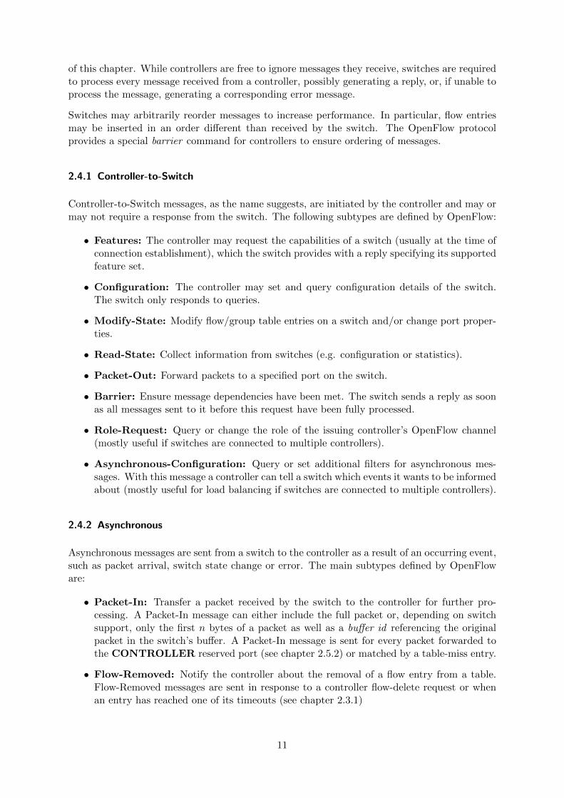
2.4.1 Controller-to-Switch
Controller-to-Switch messages, as the name suggests, are initiated by the controller and may ormay not require a response from the switch. The following subtypes are defined by OpenFlow:
• Features: The controller may request the capabilities of a switch (usually at the time ofconnection establishment), which the switch provides with a reply specifying its supportedfeature set.
• Configuration: The controller may set and query configuration details of the switch.The switch only responds to queries.
• Modify-State: Modify flow/group table entries on a switch and/or change port proper-ties.
• Read-State: Collect information from switches (e.g. configuration or statistics).
• Packet-Out: Forward packets to a specified port on the switch.
• Barrier: Ensure message dependencies have been met. The switch sends a reply as soonas all messages sent to it before this request have been fully processed.
• Role-Request: Query or change the role of the issuing controller’s OpenFlow channel(mostly useful if switches are connected to multiple controllers).
• Asynchronous-Configuration: Query or set additional filters for asynchronous mes-sages. With this message a controller can tell a switch which events it wants to be informedabout (mostly useful for load balancing if switches are connected to multiple controllers).
2.4.2 Asynchronous
Asynchronous messages are sent from a switch to the controller as a result of an occurring event,such as packet arrival, switch state change or error. The main subtypes defined by OpenFloware:
• Packet-In: Transfer a packet received by the switch to the controller for further pro-cessing. A Packet-In message can either include the full packet or, depending on switchsupport, only the first n bytes of a packet as well as a buffer id referencing the originalpacket in the switch’s buffer. A Packet-In message is sent for every packet forwarded tothe CONTROLLER reserved port (see chapter 2.5.2) or matched by a table-miss entry.
• Flow-Removed: Notify the controller about the removal of a flow entry from a table.Flow-Removed messages are sent in response to a controller flow-delete request or whenan entry has reached one of its timeouts (see chapter 2.3.1)
11
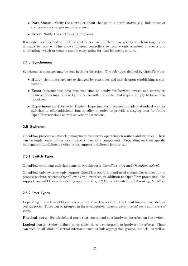
• Port-Status: Notify the controller about changes in a port’s status (e.g. link status orconfiguration changes made by a user)
• Error: Notify the controller of problems.
If a switch is connected to multiple controllers, each of them may specify which message typesit wants to receive. This allows different controllers to receive only a subset of events andnotifications which presents a simple entry point for load-balancing setups.
2.4.3 Synchronous
Synchronous messages may be sent in either direction. The sub-types defined by OpenFlow are:
• Hello: Hello messages are exchanged by controller and switch upon establishing a con-nection.
• Echo: Measure liveliness, response time or bandwidth between switch and controller.Echo requests may be sent by either controller or switch and require a reply to be sent bythe other.
• Experimenter: (Formerly Vendor) Experimenter messages provide a standard way forswitches to offer additional functionality in order to provide a staging area for futureOpenFlow revisions as well as vendor extensions.
2.5 Switches
OpenFlow presents a network management framework operating on routers and switches. Thesecan be implemented either as software or hardware components. Depending on their specificimplementation different switch types support a different feature set.
2.5.1 Switch Types
OpenFlow-compliant switches come in two flavours: OpenFlow-only and OpenFlow-hybrid.
OpenFlow-only switches only support OpenFlow operation and need a controller connection toprocess packets, whereas OpenFlow-hybrid switches, in addition to OpenFlow processing, alsosupport normal Ethernet switching operation (e.g. L2 Ethernet switching, L3 routing, VLANs).
2.5.2 Port Types
Depending on the level of OpenFlow support offered by a switch, the OpenFlow standard definescertain ports. These can be grouped in three categories: physical ports, logical ports and reservedports.
Physical ports: Switch-defined ports that correspond to a hardware interface on the switch.
Logical ports: Switch-defined ports which do not correspond to hardware interfaces. Thesecan include all kinds of virtual interfaces such as link aggregation groups, tunnels, as well as
12
VLAN or loopback interfaces. If a packet enters the switch through a physical port its metadata includes the logical ingress port in addition to its physical ingress port.
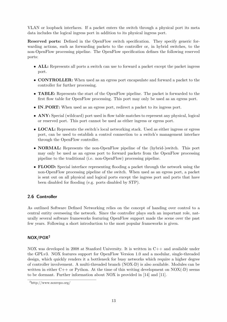
Reserved ports: Defined in the OpenFlow switch specification. They specify generic for-warding actions, such as forwarding packets to the controller or, in hybrid switches, to thenon-OpenFlow processing pipeline. The OpenFlow specification defines the following reservedports:
• ALL: Represents all ports a switch can use to forward a packet except the packet ingressport.
• CONTROLLER: When used as an egress port encapsulate and forward a packet to thecontroller for further processing.
• TABLE: Represents the start of the OpenFlow pipeline. The packet is forwarded to thefirst flow table for OpenFlow processing. This port may only be used as an egress port.
• IN PORT: When used as an egress port, redirect a packet to its ingress port.
• ANY: Special (wildcard) port used in flow table matches to represent any physical, logicalor reserved port. This port cannot be used as either ingress or egress port.
• LOCAL: Represents the switch’s local networking stack. Used as either ingress or egressport, can be used to establish a control connection to a switch’s management interfacethrough the OpenFlow controller.
• NORMAL: Represents the non-OpenFlow pipeline of the (hybrid-)switch. This portmay only be used as an egress port to forward packets from the OpenFlow processingpipeline to the traditional (i.e. non-OpenFlow) processing pipeline.
• FLOOD: Special interface representing flooding a packet through the network using thenon-OpenFlow processing pipeline of the switch. When used as an egress port, a packetis sent out on all physical and logical ports except the ingress port and ports that havebeen disabled for flooding (e.g. ports disabled by STP).
2.6 Controller
As outlined Software Defined Networking relies on the concept of handing over control to acentral entity overseeing the network. Since the controller plays such an important role, nat-urally several software frameworks featuring OpenFlow support made the scene over the pastfew years. Following a short introduction to the most popular frameworks is given.
NOX/POX2
NOX was developed in 2008 at Stanford University. It is written in C++ and available underthe GPLv3. NOX features support for OpenFlow Version 1.0 and a modular, single-threadeddesign, which quickly renders it a bottleneck for busy networks which require a higher degreeof controller involvement. A multi-threaded branch (NOX-D) is also available. Modules can bewritten in either C++ or Python. At the time of this writing development on NOX(-D) seemsto be dormant. Further information about NOX is provided in [14] and [11].
2http://www.noxrepo.org/
13
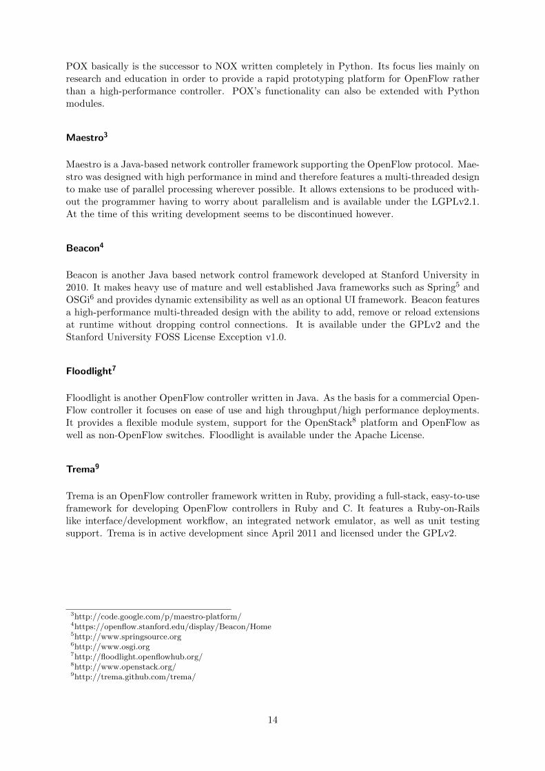
POX basically is the successor to NOX written completely in Python. Its focus lies mainly onresearch and education in order to provide a rapid prototyping platform for OpenFlow ratherthan a high-performance controller. POX’s functionality can also be extended with Pythonmodules.
Maestro3
Maestro is a Java-based network controller framework supporting the OpenFlow protocol. Mae-stro was designed with high performance in mind and therefore features a multi-threaded designto make use of parallel processing wherever possible. It allows extensions to be produced with-out the programmer having to worry about parallelism and is available under the LGPLv2.1.At the time of this writing development seems to be discontinued however.
Beacon4
Beacon is another Java based network control framework developed at Stanford University in2010. It makes heavy use of mature and well established Java frameworks such as Spring5 andOSGi6 and provides dynamic extensibility as well as an optional UI framework. Beacon featuresa high-performance multi-threaded design with the ability to add, remove or reload extensionsat runtime without dropping control connections. It is available under the GPLv2 and theStanford University FOSS License Exception v1.0.
Floodlight7
Floodlight is another OpenFlow controller written in Java. As the basis for a commercial Open-Flow controller it focuses on ease of use and high throughput/high performance deployments.It provides a flexible module system, support for the OpenStack8 platform and OpenFlow aswell as non-OpenFlow switches. Floodlight is available under the Apache License.
Trema9
Trema is an OpenFlow controller framework written in Ruby, providing a full-stack, easy-to-useframework for developing OpenFlow controllers in Ruby and C. It features a Ruby-on-Railslike interface/development workflow, an integrated network emulator, as well as unit testingsupport. Trema is in active development since April 2011 and licensed under the GPLv2.
3http://code.google.com/p/maestro-platform/4https://openflow.stanford.edu/display/Beacon/Home5http://www.springsource.org6http://www.osgi.org7http://floodlight.openflowhub.org/8http://www.openstack.org/9http://trema.github.com/trema/
14
3 Predictably Reliable Real-Time Transport (PRRT)
PRRT is a transport layer protocol based on UDP. It provides a highly scalable hybrid er-ror control and correction scheme, which enables applications to reliably transmit informationthrough a network under the constraints of a given time and loss budget [9, 10] and makes useof the Simplified Gilbert-Elliot Model [8] to map error patterns in the communication channel.
As a stateless protocol PRRT does not require any connection setup prior to sending data andoffers multicast support, but unlike UDP also provides monitoring of a connection’s packet lossrate and round trip time, as well as packet reordering. It features predictable reliability undera predictable delay. It does so by employing a loss-tolerant error correction scheme using aType-II-HEC-based approach called Adaptive Hybrid Error Correction (AHEC) which makesit ideal for heavily media-oriented applications.
Traditional transport protocols usually try to proactively eliminate residual error by encodinginformation using Forward Error Correction (FEC) mechanisms producing a certain amount ofredundant data which is then transmitted alongside the original information. If packet lossesoccur up to a certain degree, the original information can still be reconstructed by the receiverusing the redundant data.
Another popular approach is the use of Automatic Repeat reQuests (ARQ). When using ARQdata is encoded prior to transmission, but the redundant portion of the encoded data is nottransmitted as a whole. A sender only transmits just enough information for a receiver to be ableto reconstruct the original information. If packet losses occur, the receiver requests additionalpieces of data until enough data has been collected to reconstruct the original information. Amore naive approach requests retransmission of missing packets instead of an arbitrary piece ofencoded data.
Instead of only employing either ARQ or FEC the AHEC mechanism used by PRRT uses acombination of these proactive and reactive error correction schemes trying to find the optimalcombination between FEC and ARQ by continuously solving an optimization problem subjectto the application’s timing constraints and the current state of the network. This enables PRRTto minimize the overall redundancy on the network.
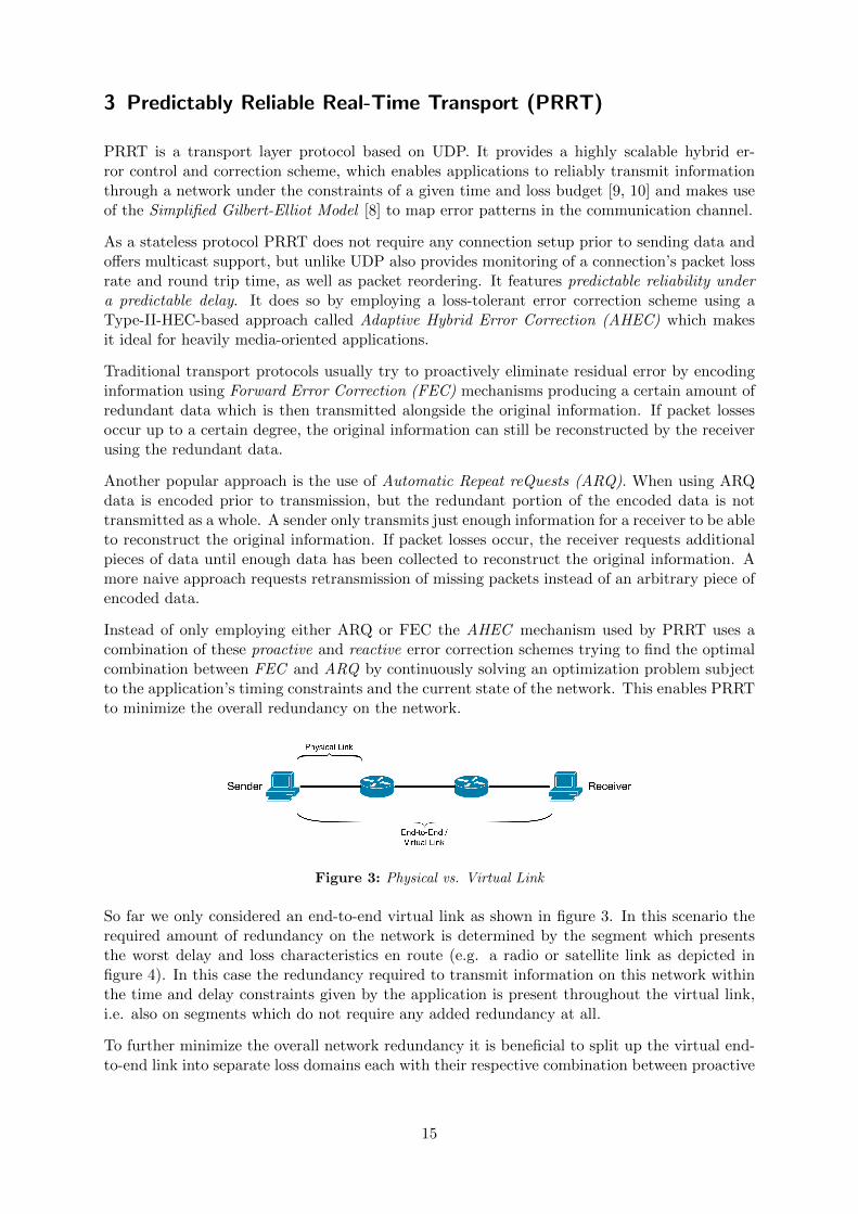
Figure 3: Physical vs. Virtual Link
So far we only considered an end-to-end virtual link as shown in figure 3. In this scenario therequired amount of redundancy on the network is determined by the segment which presentsthe worst delay and loss characteristics en route (e.g. a radio or satellite link as depicted infigure 4). In this case the redundancy required to transmit information on this network withinthe time and delay constraints given by the application is present throughout the virtual link,i.e. also on segments which do not require any added redundancy at all.
To further minimize the overall network redundancy it is beneficial to split up the virtual end-to-end link into separate loss domains each with their respective combination between proactive
15
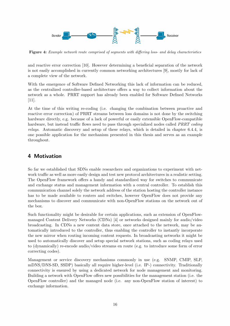
Figure 4: Example network route comprised of segments with differing loss- and delay characteristics
and reactive error correction [10]. However determining a beneficial separation of the networkis not easily accomplished in currently common networking architectures [9], mostly for lack ofa complete view of the network.
With the emergence of Software Defined Networking this lack of information can be reduced,as the centralized controller-based architecture offers a way to collect information about thenetwork as a whole. PRRT support has already been enabled for Software Defined Networks[11].
At the time of this writing re-coding (i.e. changing the combination between proactive andreactive error correction) of PRRT streams between loss domains is not done by the switchinghardware directly, e.g. because of a lack of powerful or easily extensible OpenFlow-compatiblehardware, but instead traffic flows need to pass through specialized nodes called PRRT codingrelays. Automatic discovery and setup of these relays, which is detailed in chapter 6.4.4, isone possible application for the mechanism presented in this thesis and serves as an examplethroughout.
4 Motivation
So far we established that SDNs enable researchers and organizations to experiment with net-work traffic as well as more easily design and test new protocol architectures in a realistic setting.The OpenFlow framework offers a handy and standardized way for switches to communicateand exchange status and management information with a central controller. To establish thiscommunication channel solely the network address of the station hosting the controller instancehas to be made available to routers and switches, however OpenFlow does not provide anymechanisms to discover and communicate with non-OpenFlow stations on the network out ofthe box.
Such functionality might be desirable for certain applications, such as extension of OpenFlow-managed Content Delivery Networks (CDNs) [4] or networks designed mainly for audio/videobroadcasting. In CDNs a new content data store, once attached to the network, may be au-tomatically introduced to the controller, thus enabling the controller to instantly incorporatethe new mirror when routing incoming content requests. In broadcasting networks it might beused to automatically discover and setup special network stations, such as coding relays usedto (dynamically) re-encode audio/video streams en route (e.g. to introduce some form of errorcorrecting codes).
Management or service discovery mechanisms commonly in use (e.g. SNMP, CMIP, SLP,mDNS/DNS-SD, SSDP) basically all require higher-level (i.e. IP-) connectivity. Traditionallyconnectivity is ensured by using a dedicated network for node management and monitoring.Building a network with OpenFlow offers new possibilities for the management station (i.e. theOpenFlow controller) and the managed node (i.e. any non-OpenFlow station of interest) toexchange information.
16
Since OpenFlow controllers can be arbitrarily programmed, the OpenFlow discovery processcan be easily augmented to introduce a communications channel for non-OpenFlow stations.
In the following we devise an efficient way for an OpenFlow controller to discover and establishcommunications with non-OpenFlow stations attached to an OpenFlow Network which cleverlyuses features provided by the OpenFlow protocol in order to avoid the necessity for additionalnetwork components. Our goal is to introduce as little additional management effort to thenetwork and/or station configuration as possible.
In this thesis we assume that the network is managed completely by a central controller instanceusing the OpenFlow protocol. Traditionally, stations wanting or requiring exchange informationwith the controller would establish a TCP or UDP connection to the controller instance. Forpackets to reach the controller, network operators have to provide a route to the controller,either through the data path of the existing network or by attaching the OpenFlow controllerand the managed nodes to an additional physical or virtualized network. This way the networkintegrator has to discriminate the role of the station which is attached to the network.
Instead we propose discrimination is performed by the network. A station connected to anOpenFlow capable switch advertises its role and capabilities, if any, and the controller can reactand decide on how best to make use of the newly introduced station. In preference to settingup an additional route between such stations and the controller, we make use of the alreadyestablished OpenFlow control connection between controller and switches by using OpenFlow’sencapsulation and forwarding mechanisms, thus further decreasing initial configuration over-head.
Instead of designing and introducing a proprietary protocol we show how to extend the wellestablished Link Layer Discovery Protocol (LLDP) [1]. LLDP can be easily extended to allowadvertisement of additional (i.e. more specific) information and, although being designed mainlyfor advertising network stations and their capabilities, also for sending a limited amount ofcontrol information back to any advertised station. A more detailed explanation of LLDP isgiven in chapter 5.
5 LLDP (IEEE 802.3ab)
The Link Layer Discovery Protocol (LLDP) allows stations attached to an IEEE 802 LANto advertise their major capabilities, management address(es) and identity to other stationsconnected to the same IEEE 802 LAN. Usually the distributed information is stored by itsrecipients in one or more standard Management Information Bases (MIB), allowing NetworkManagement Software to query the information using a management protocol such as SNMP.
LLDP is a one-way protocol, i.e. it can transmit information about capabilities and status ofa system, however it does not contain any mechanisms for soliciting for information nor doesit provide a means to acknowledge receipt of a transmission. Information is distributed ina stateless/connectionless manner using single frames sent to a designated broadcast addressupon a change of the system configuration or transmit timer expiration. A LAN station canhost more than one LLDP agent (e.g. one per network interface).
5.1 Packet Structure
LLDP transmits information in a single MAC service request (for IEEE 802.3 Ethernet: onesingle Ethernet frame). The resulting frame contains a standard frame header (source address,
17
Name: Address: Scope:
Nearest Bridge 01-80-C2-00-00-0E Propagation limited to singlephysical link
Nearest non-TPMR1 Bridge 01-80-C2-00-00-03 Propagation limited by allnon-TPMR bridges (for use inprovider bridged networks)
Nearest Customer Bridge 01-80-C2-00-00-00 Propagation constrained bycustomer bridges
1 Two Port MAC Relay
Table 2: Destination MAC addresses for LLDP packets
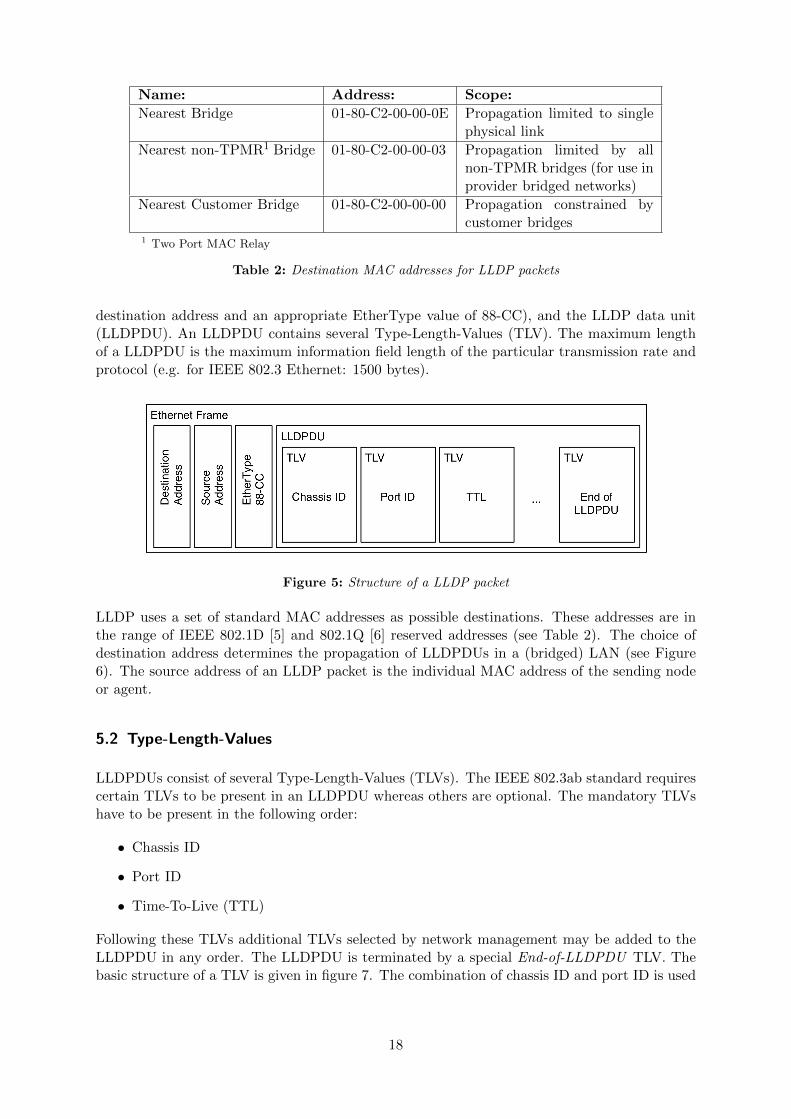
destination address and an appropriate EtherType value of 88-CC), and the LLDP data unit(LLDPDU). An LLDPDU contains several Type-Length-Values (TLV). The maximum lengthof a LLDPDU is the maximum information field length of the particular transmission rate andprotocol (e.g. for IEEE 802.3 Ethernet: 1500 bytes).
Figure 5: Structure of a LLDP packet
LLDP uses a set of standard MAC addresses as possible destinations. These addresses are inthe range of IEEE 802.1D [5] and 802.1Q [6] reserved addresses (see Table 2). The choice ofdestination address determines the propagation of LLDPDUs in a (bridged) LAN (see Figure6). The source address of an LLDP packet is the individual MAC address of the sending nodeor agent.
5.2 Type-Length-Values
LLDPDUs consist of several Type-Length-Values (TLVs). The IEEE 802.3ab standard requirescertain TLVs to be present in an LLDPDU whereas others are optional. The mandatory TLVshave to be present in the following order:
• Chassis ID
• Port ID
• Time-To-Live (TTL)
Following these TLVs additional TLVs selected by network management may be added to theLLDPDU in any order. The LLDPDU is terminated by a special End-of-LLDPDU TLV. Thebasic structure of a TLV is given in figure 7. The combination of chassis ID and port ID is used
18
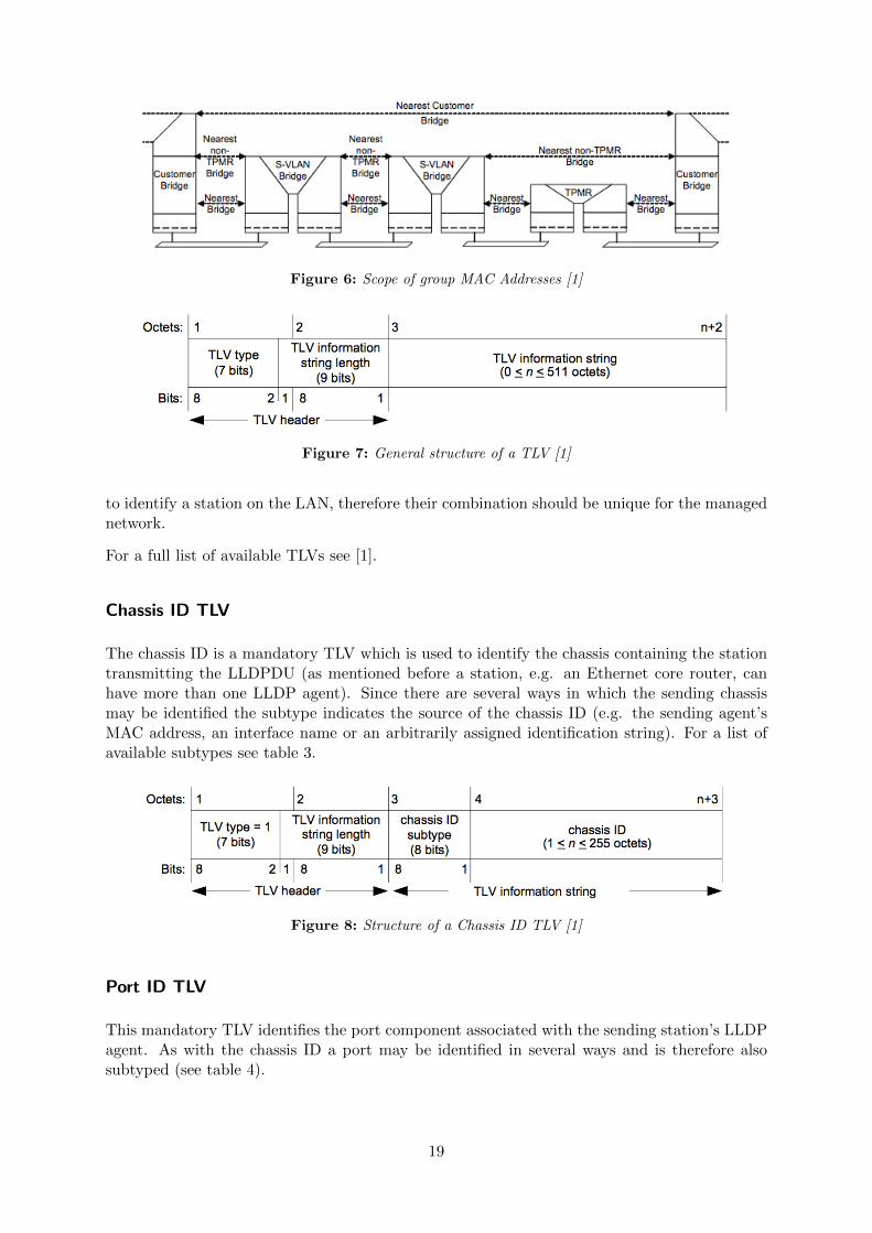
Figure 6: Scope of group MAC Addresses [1]
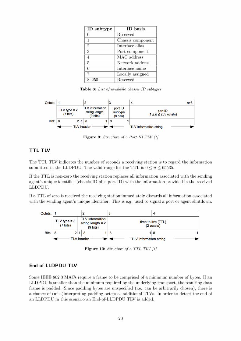
Figure 7: General structure of a TLV [1]
to identify a station on the LAN, therefore their combination should be unique for the managednetwork.
For a full list of available TLVs see [1].
Chassis ID TLV
The chassis ID is a mandatory TLV which is used to identify the chassis containing the stationtransmitting the LLDPDU (as mentioned before a station, e.g. an Ethernet core router, canhave more than one LLDP agent). Since there are several ways in which the sending chassismay be identified the subtype indicates the source of the chassis ID (e.g. the sending agent’sMAC address, an interface name or an arbitrarily assigned identification string). For a list ofavailable subtypes see table 3.
Figure 8: Structure of a Chassis ID TLV [1]
Port ID TLV
This mandatory TLV identifies the port component associated with the sending station’s LLDPagent. As with the chassis ID a port may be identified in several ways and is therefore alsosubtyped (see table 4).
19
ID subtype ID basis
0 Reserved
1 Chassis component
2 Interface alias
3 Port component
4 MAC address
5 Network address
6 Interface name
7 Locally assigned
8–255 Reserved
Table 3: List of available chassis ID subtypes
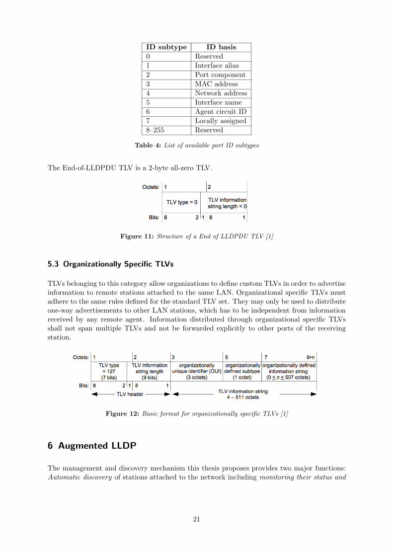
Figure 9: Structure of a Port ID TLV [1]
TTL TLV
The TTL TLV indicates the number of seconds a receiving station is to regard the informationsubmitted in the LLDPDU. The valid range for the TTL is 0 ≤ n ≤ 65535.
If the TTL is non-zero the receiving station replaces all information associated with the sendingagent’s unique identifier (chassis ID plus port ID) with the information provided in the receivedLLDPDU.
If a TTL of zero is received the receiving station immediately discards all information associatedwith the sending agent’s unique identifier. This is e.g. used to signal a port or agent shutdown.
Figure 10: Structure of a TTL TLV [1]
End-of-LLDPDU TLV
Some IEEE 802.3 MACs require a frame to be comprised of a minimum number of bytes. If anLLDPDU is smaller than the minimum required by the underlying transport, the resulting dataframe is padded. Since padding bytes are unspecified (i.e. can be arbitrarily chosen), there isa chance of (mis-)interpreting padding octets as additional TLVs. In order to detect the end ofan LLDPDU in this scenario an End-of-LLDPDU TLV is added.
20
ID subtype ID basis
0 Reserved
1 Interface alias
2 Port component
3 MAC address
4 Network address
5 Interface name
6 Agent circuit ID
7 Locally assigned
8–255 Reserved
Table 4: List of available port ID subtypes
The End-of-LLDPDU TLV is a 2-byte all-zero TLV.
Figure 11: Structure of a End of LLDPDU TLV [1]
5.3 Organizationally Specific TLVs
TLVs belonging to this category allow organizations to define custom TLVs in order to advertiseinformation to remote stations attached to the same LAN. Organizational specific TLVs mustadhere to the same rules defined for the standard TLV set. They may only be used to distributeone-way advertisements to other LAN stations, which has to be independent from informationreceived by any remote agent. Information distributed through organizational specific TLVsshall not span multiple TLVs and not be forwarded explicitly to other ports of the receivingstation.
Figure 12: Basic format for organizationally specific TLVs [1]
6 Augmented LLDP
The management and discovery mechanism this thesis proposes provides two major functions:Automatic discovery of stations attached to the network including monitoring their status and
21
availability as well as configuring them by propagating management information from the Open-Flow controller to the managed stations. Both functions can be covered using LLDP.
For functions not provided by LLDP out of the box it is easily possible to augment LLDP’sfeature set by using the organizationally specific TLVs defined in the LLDP specification whilestill adhering to the operational limits defined in the LLDP standard definition [1].
6.1 Node Discovery and Supervision
Automatic discovery is already provided by legacy LLDP. Since LLDP periodically advertisesinformation about a station connected to the network, monitoring a station’s basic availabilitycan be covered implicitly by passively collecting and interpreting LLDP packets received fromthe network in order to determine a station’s basic availability.
The organizationally specific TLVs defined in the LLDP specification provide a handy way toextend LLDPs functionality. In order to aid node discrimination we propose the introductionof special organizationally specific TLVs to advertise the role of a network station. These mayalso be used to further improve station supervision by introducing additional metrics whichprovide more useful information to the controller (e.g. remaining storage capacity of a datastore, current system load of a video relay or its configuration state).
6.2 Node Configuration
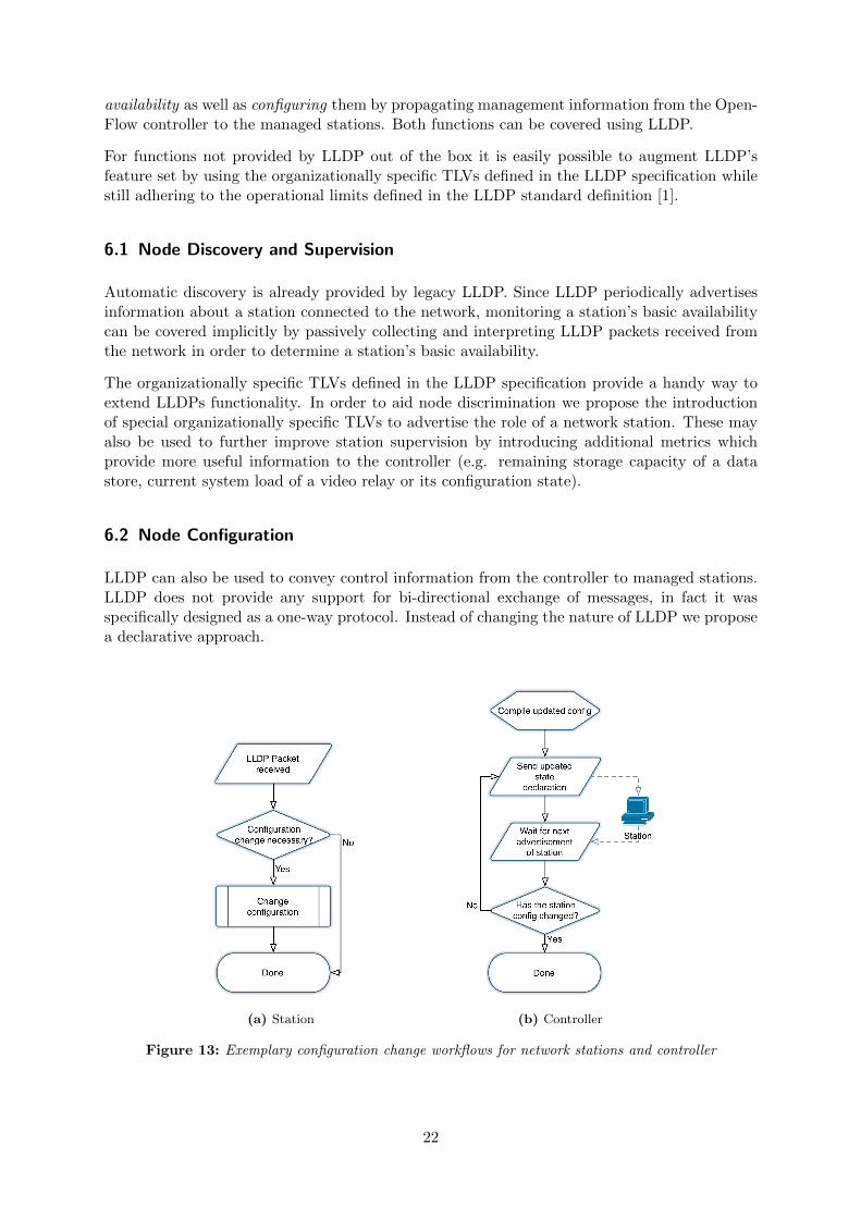
LLDP can also be used to convey control information from the controller to managed stations.LLDP does not provide any support for bi-directional exchange of messages, in fact it wasspecifically designed as a one-way protocol. Instead of changing the nature of LLDP we proposea declarative approach.
(a) Station (b) Controller
Figure 13: Exemplary configuration change workflows for network stations and controller
22
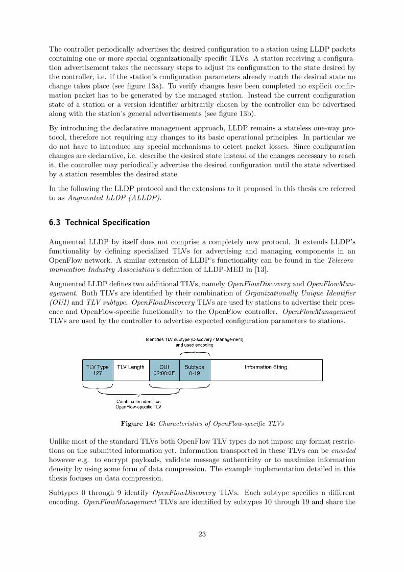
The controller periodically advertises the desired configuration to a station using LLDP packetscontaining one or more special organizationally specific TLVs. A station receiving a configura-tion advertisement takes the necessary steps to adjust its configuration to the state desired bythe controller, i.e. if the station’s configuration parameters already match the desired state nochange takes place (see figure 13a). To verify changes have been completed no explicit confir-mation packet has to be generated by the managed station. Instead the current configurationstate of a station or a version identifier arbitrarily chosen by the controller can be advertisedalong with the station’s general advertisements (see figure 13b).
By introducing the declarative management approach, LLDP remains a stateless one-way pro-tocol, therefore not requiring any changes to its basic operational principles. In particular wedo not have to introduce any special mechanisms to detect packet losses. Since configurationchanges are declarative, i.e. describe the desired state instead of the changes necessary to reachit, the controller may periodically advertise the desired configuration until the state advertisedby a station resembles the desired state.
In the following the LLDP protocol and the extensions to it proposed in this thesis are referredto as Augmented LLDP (ALLDP).
6.3 Technical Specification
Augmented LLDP by itself does not comprise a completely new protocol. It extends LLDP’sfunctionality by defining specialized TLVs for advertising and managing components in anOpenFlow network. A similar extension of LLDP’s functionality can be found in the Telecom-munication Industry Association’s definition of LLDP-MED in [13].
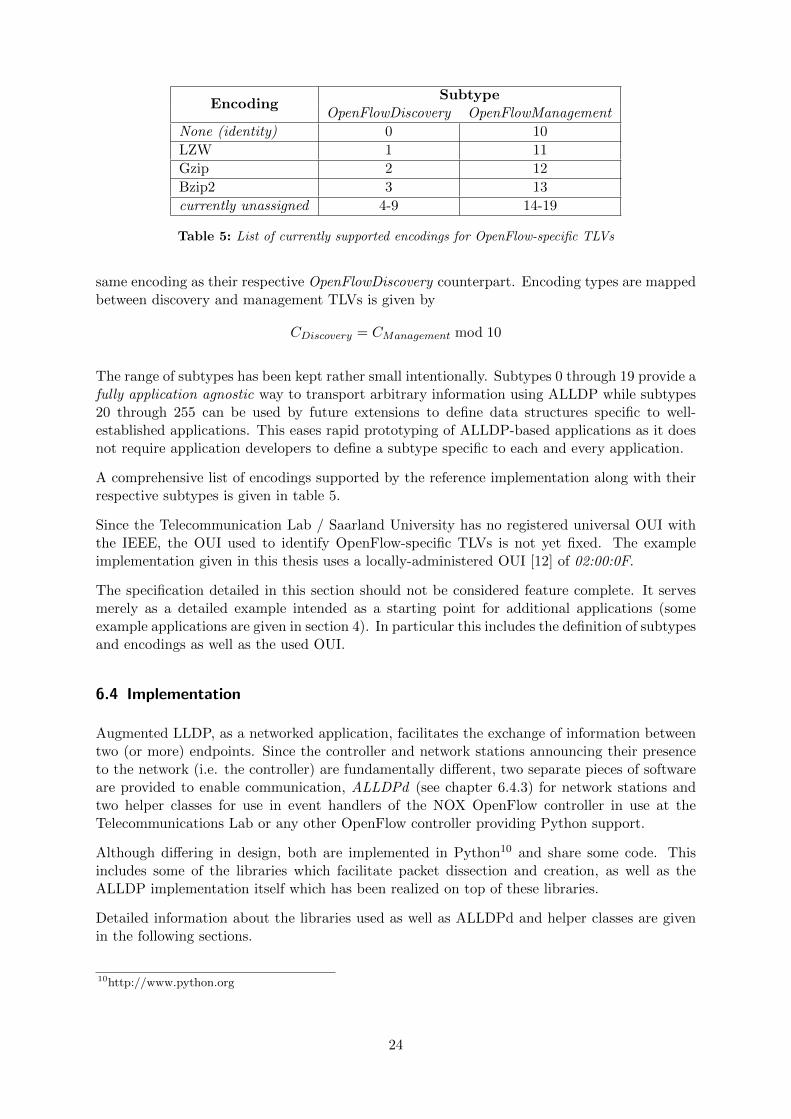
Augmented LLDP defines two additional TLVs, namely OpenFlowDiscovery and OpenFlowMan-agement. Both TLVs are identified by their combination of Organizationally Unique Identifier(OUI) and TLV subtype. OpenFlowDiscovery TLVs are used by stations to advertise their pres-ence and OpenFlow-specific functionality to the OpenFlow controller. OpenFlowManagementTLVs are used by the controller to advertise expected configuration parameters to stations.
Figure 14: Characteristics of OpenFlow-specific TLVs
Unlike most of the standard TLVs both OpenFlow TLV types do not impose any format restric-tions on the submitted information yet. Information transported in these TLVs can be encodedhowever e.g. to encrypt payloads, validate message authenticity or to maximize informationdensity by using some form of data compression. The example implementation detailed in thisthesis focuses on data compression.
Subtypes 0 through 9 identify OpenFlowDiscovery TLVs. Each subtype specifies a differentencoding. OpenFlowManagement TLVs are identified by subtypes 10 through 19 and share the
23
EncodingSubtype
OpenFlowDiscovery OpenFlowManagement
None (identity) 0 10
LZW 1 11
Gzip 2 12
Bzip2 3 13
currently unassigned 4-9 14-19
Table 5: List of currently supported encodings for OpenFlow-specific TLVs
same encoding as their respective OpenFlowDiscovery counterpart. Encoding types are mappedbetween discovery and management TLVs is given by
CDiscovery = CManagement mod 10
The range of subtypes has been kept rather small intentionally. Subtypes 0 through 19 provide afully application agnostic way to transport arbitrary information using ALLDP while subtypes20 through 255 can be used by future extensions to define data structures specific to well-established applications. This eases rapid prototyping of ALLDP-based applications as it doesnot require application developers to define a subtype specific to each and every application.
A comprehensive list of encodings supported by the reference implementation along with theirrespective subtypes is given in table 5.
Since the Telecommunication Lab / Saarland University has no registered universal OUI withthe IEEE, the OUI used to identify OpenFlow-specific TLVs is not yet fixed. The exampleimplementation given in this thesis uses a locally-administered OUI [12] of 02:00:0F.
The specification detailed in this section should not be considered feature complete. It servesmerely as a detailed example intended as a starting point for additional applications (someexample applications are given in section 4). In particular this includes the definition of subtypesand encodings as well as the used OUI.
6.4 Implementation
Augmented LLDP, as a networked application, facilitates the exchange of information betweentwo (or more) endpoints. Since the controller and network stations announcing their presenceto the network (i.e. the controller) are fundamentally different, two separate pieces of softwareare provided to enable communication, ALLDPd (see chapter 6.4.3) for network stations andtwo helper classes for use in event handlers of the NOX OpenFlow controller in use at theTelecommunications Lab or any other OpenFlow controller providing Python support.
Although differing in design, both are implemented in Python10 and share some code. Thisincludes some of the libraries which facilitate packet dissection and creation, as well as theALLDP implementation itself which has been realized on top of these libraries.
Detailed information about the libraries used as well as ALLDPd and helper classes are givenin the following sections.
10http://www.python.org
24
6.4.1 dpkt
The dpkt11 module is a lightweight packet dissection and creation library for the Python pro-gramming language published under the BSD 3-clause license. It offers an easy way to parse andcompile packets for protocols operating on different levels of the ISO/OSI model. Supportedprotocols include but are not limited to Ethernet, IPX, IPv4, IPv6, ICMPv4, ICMPv6, SCTP,PPP, TCP, UDP, STP, DNS and HTTP. Additional protocols can be easily added on top ofexisting ones or on top of the packet generalization offered by dpkt.
The vanilla version of dpkt does not provide support for LLDP out of the box, however auser-contributed basic LLDP module is available in the project’s issue tracker12. Due to bugsin the module’s implementation LLDP packets could not be parsed reliably because the Sys-temCapabilities, ManagementAddress and Organizationally-Specific TLVs were not processedcorrectly. These bugs have been fixed in the making of this thesis and an updated version hasbeen included in the example implementation.
The implementation of ALLDP has been completed on top of the dpkt LLDP module. SinceALLDP identifies certain organizationally-specific TLVs as OpenFlow-related based on the com-bination of the included non-universal OUI and subtype, its functionality has not been includedin the LLDP module directly, but in a separate ALLDP module instead. This avoids uninten-tional parsing of seemingly OpenFlow-related organizationally-specific TLVs in non-OpenFlowapplications.
In practice this means that the import sequence in Python is important.Since LLDP and ALLDP share the same ethertype only the last module imported by Pythonwill be the registered parser for LLDP frames in dpkt. If constants or TLV classes defined in theLLDP module are required one should make sure any imports related to LLDP are listed beforeany ALLDP-related imports. Since ALLDP comprises a superset of LLDP, cases requiring boththe LLDP and ALLDP modules to be loaded should be very rare.
6.4.2 pypcap
Pypcap13 is a simplified object-oriented Python module for libpcap14 published under the BSD3-clause license, which provides a high-level interface to packet capture systems provided by theoperating system. Implementations exist for a variety of platforms, such as Linux, BSD andWindows15. Most of them are supported by pypcap.
Pypcap is used by ALLDPd (see chapter 6.4.3) to filter incoming packets for LLDP packets.By using libpcap packet filtering is facilitated by the operating system, which offers betterperformance compared to transferring all packets to userspace for inspection.
6.4.3 ALLDPd
ALLDPd is a forking daemon written in Python which is used by stations on the networkto advertise themselves using ALLDP. By default it announces the station’s presence on the
11http://code.google.com/p/dpkt/12http://code.google.com/p/dpkt/issues/detail?id=65#c313http://code.google.com/p/pypcap/14http://www.tcpdump.org15http://www.winpcap.org/
25
network by distributing the minimal set of TLVs (i.e. ChassisId, PortID and TTL) required bythe LLDP standard [1]. Parameters such as the network interface, the TTL for announcements,the sending interval as well as the LLDP scope can be changed via command line options.
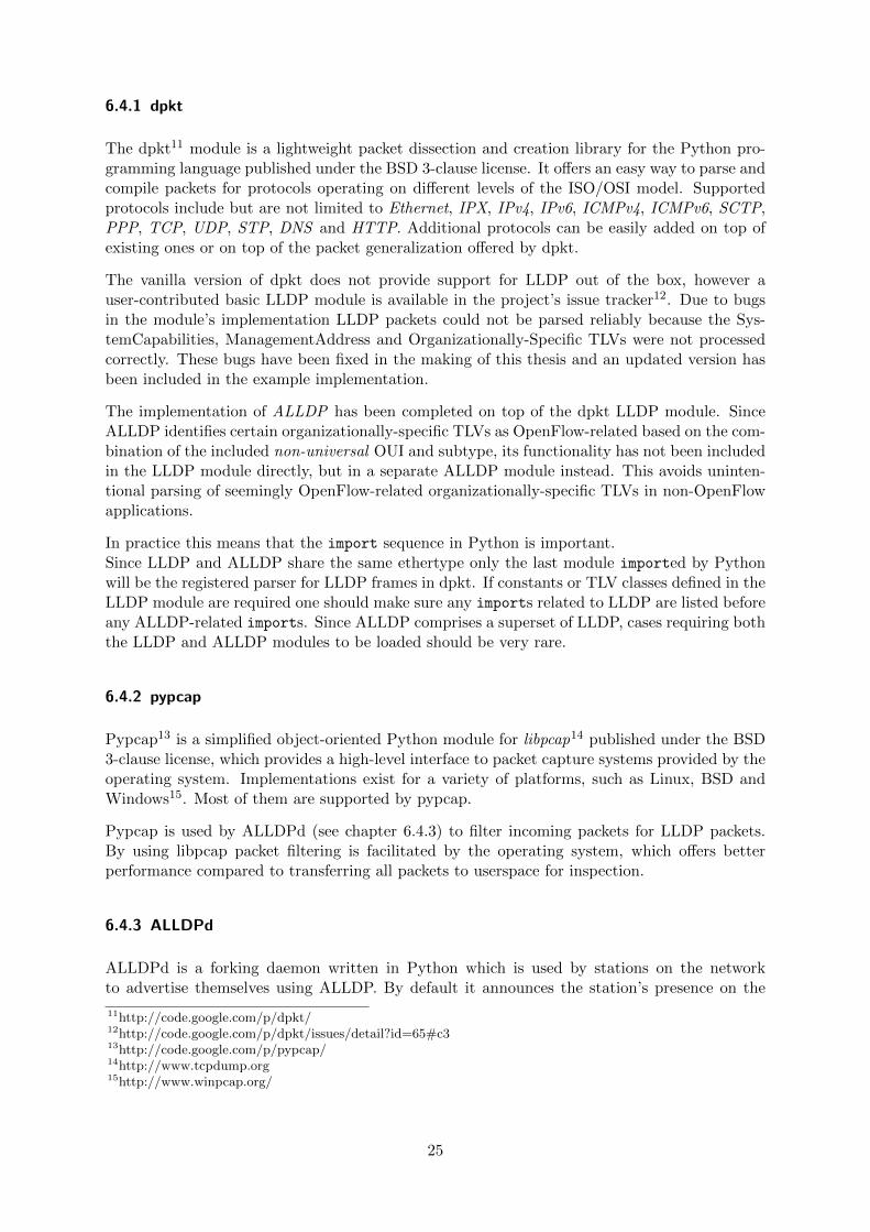
It features a simple plugin interface supporting different implementations for generation andprocessing of the OpenFlow-specific TLVs introduced in section 6.3 as well as a logging facilitywith automatic log file rotation based on the logging module from Python’s standard library.
Figure 15: ALLDPd architecture
Although implemented in Python and therefore platform-independent in theory, it only offerssupport for the Linux platform, as it makes use of raw sockets provided by the BSD socketAPI of the Linux operating system. Support for e.g. Windows or BSD-based platforms can beadded with little additional work however.
ALLDPd is part of the reference implementation of ALLDP compiled in this thesis.
General Structure The core functionality of ALLDPd is provided by the ALLDPAgent class.
Each instance of ALLDPAgent is bound to a specific network interface of the host system. Bydefault it sends out ALLDP advertisements with a TTL of 120 seconds on the bound inter-face every 30 seconds. As a subclass of Python’s built-in Thread class multiple instances ofALLDPAgent can be active for different interfaces of the host at the same time, however, as aproof of concept, ALLDPd does not make use of multithreading. Instead it just calls the run()
method of a single ALLDPAgent instance. The ALLDPAgent class makes use of Python’s loggingmodule to facilitate logging of operational messages and uses dpkt and pypcap to generate, filterand parse ALLDP frames.
Plugins To ease development and testing of new ALLDP applications in OpenFlow networksALLDPAgent offers the possibility to use arbitrary functions for generation and processing ofOpenFlowManagement and OpenFlowDiscovery TLVs. These functions can be assigned to oneor multiple ALLDPAgent instances upon instantiation.
ALLDPd offers support for these generic functions in the form of a simple plugin interface. Aplugin, as far as ALLDPd is concerned, is a simple Python module (i.e. .py file) providing twomethods named consume and produce. Their signatures are as follows:
def produce(*args) : @returns buf
def consume(buf, *args) : @returns nil
26

produce() returns an information string to be included in an OpenFlowDiscovery TLV.consume() is called by ALLDPAgent once for every OpenFlowManagement TLV received on itsbound interface.
Processing of OpenFlowManagement TLVs is not done in real-time, but only just before sendingout the next advertisement (also before the call to produce(), so that any configuration changesshow up immediately in the next advertisement).
Plugins for ALLDPd have to be copied to the modules/ subfolder of the ALLDPd installation.A plugin’s name can be arbitrarily chosen as long as it conforms to Python’s module namingconventions.
By default ALLDPd runs without any plugins, falling back to only sending LLDP announce-ments (i.e. without any OpenFlow TLVs). To start ALLDPd while enabling a specific plugin,the name of the plugin (without the .py extension) can be given as a second argument toalldpd.py (further details are given in chapter 6.5).
Control Flow Once the main loop of an ALLDPAgent instance is started by calling its run()
method it first creates sockets for the bound interface. ALLDPAgent uses different sockets forsending and receiving. A receiving socket is only created if a consumer has been registered uponagent instantiation.
27
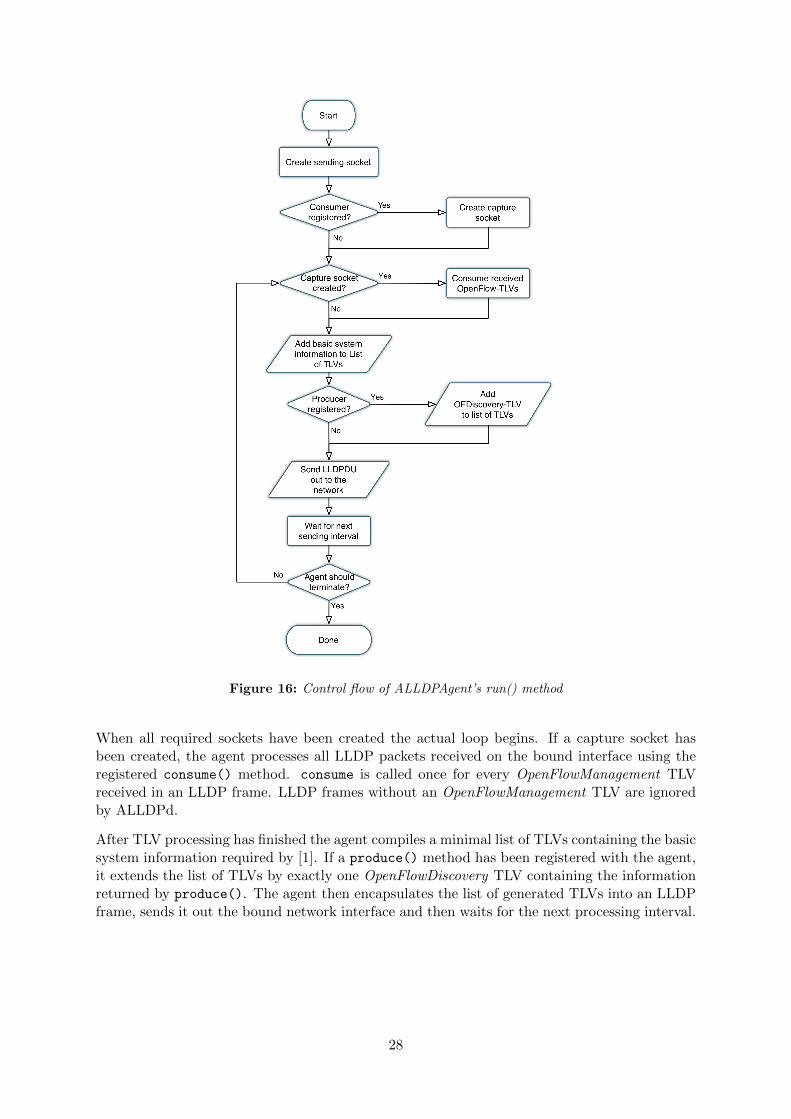
Figure 16: Control flow of ALLDPAgent’s run() method
When all required sockets have been created the actual loop begins. If a capture socket hasbeen created, the agent processes all LLDP packets received on the bound interface using theregistered consume() method. consume is called once for every OpenFlowManagement TLVreceived in an LLDP frame. LLDP frames without an OpenFlowManagement TLV are ignoredby ALLDPd.
After TLV processing has finished the agent compiles a minimal list of TLVs containing the basicsystem information required by [1]. If a produce() method has been registered with the agent,it extends the list of TLVs by exactly one OpenFlowDiscovery TLV containing the informationreturned by produce(). The agent then encapsulates the list of generated TLVs into an LLDPframe, sends it out the bound network interface and then waits for the next processing interval.
28
6.4.4 PRRT Plugin for ALLDPd
As detailed in chapter 3 the PRRT protocol offers the possibility to change the transportencoding of multimedia streams en route. Decoding and re-encoding of data is facilitated byPRRT relay nodes.
The PRRT plugin for ALLDPd is used to collect information about PRRT streams present onsuch nodes.
The current Linux in-kernel implementation of PRRT can support an arbitrary number ofmultimedia streams at a given time (limited only by bandwidth and processing power). Codingparameters can be different for each stream, which is bound to exactly one relay instance anduses a receiving and a sending socket both identified by their IP address and port combination.Internally each socket is identified by its socket handle.
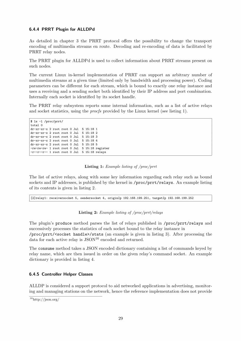
The PRRT relay subsystem reports some internal information, such as a list of active relaysand socket statistics, using the procfs provided by the Linux kernel (see listing 1).
$ ls -l /proc/prrt/
total 0
dr-xr-xr-x 2 root root 0 Jul 5 15:18 1
dr-xr-xr-x 2 root root 0 Jul 5 15:18 2
dr-xr-xr-x 2 root root 0 Jul 5 15:18 3
dr-xr-xr-x 2 root root 0 Jul 5 15:18 4
dr-xr-xr-x 2 root root 0 Jul 5 15:18 5
-rw-rw-rw- 1 root root 0 Jul 5 15:18 register
-r--r--r-- 1 root root 0 Jul 5 15:18 relays
Listing 1: Example listing of /proc/prrt
The list of active relays, along with some key information regarding each relay such as boundsockets and IP addresses, is published by the kernel in /proc/prrt/relays. An example listingof its contents is given in listing 2.
[2]relay1: receiversocket 5, sendersocket 4, originIp 192.168.199.251, targetIp 192.168.199.252
Listing 2: Example listing of /proc/prrt/relays
The plugin’s produce method parses the list of relays published in /proc/prrt/relays andsuccessively processes the statistics of each socket bound to the relay instance in/proc/prrt/<socket handle>/stats (an example is given in listing 3). After processing thedata for each active relay is JSON16 encoded and returned.
The consume method takes a JSON encoded dictionary containing a list of commands keyed byrelay name, which are then issued in order on the given relay’s command socket. An exampledictionary is provided in listing 4.
6.4.5 Controller Helper Classes
ALLDP is considered a support protocol to aid networked applications in advertising, monitor-ing and managing stations on the network, hence the reference implementation does not provide
16http://json.org/
29

Sent data: 0
Sent redundancy: 0
Lost packets: 0
Dropped packets: 0
Missed packets: 0
Received data: 0
Received redundancy: 0
Last GRTT: 15
Last FTT: 0
Last GFTT: 0
Queue Delay: 0
Last PLR: 0
Last GPLR: 0
Num Gaps: 1
Num Bursts: 0
Gap Length: 513
Burst Length: 0
Num GGaps: 0
Num GBursts: 0
Gap GLength: 0
Burst GLength: 0
Packet Interval: 0
BW Estimate: 5000
Listing 3: Example listing of PRRT socket statistics
{ ’relay1’: [
’addreceiver 192.168.2.12 172.16.10.4’,
’reroute 2 5’,
’stopReplacements 5 1’
]}
Listing 4: Example PRRT command dictionary
a stand-alone module for the NOX controller. To facilitate ALLDP processing at the controllerside this thesis provides a set of minimalist helper classes instead which can be easily includedinto applications built for NOX or any other Python-based or Python-supporting controller.Following the modules provided in the reference implementation are further detailed.
ALLDPCollection ALLDPCollection is a helper class of the ALLDP reference implementation.It provides a simplified interface for parsing and collection of information submitted by a stationusing ALLDP. It behaves like a standard Python dictionary and uses the Chassis ID submittedby a station as keys. It provides two additional ALLDP-specific methods:
• parse(buf): Parses an Ethernet frame and tries to extract the included LLDPDU andits OpenFlowManagement TLVs. The information string contained therein is added tothe collection along with some administrative meta data.
• purge(): When called purges outdated information (i.e. submitted information whoseTTL has elapsed) from the collection. Purging of the collection is not done automaticallyfor performance considerations.
A lookup on the collection yields a simple data structure in the following format.
30
{
’type’ : ’prrt’,
’valid_until’ : now() + tlv.ttl,
’dpid’ : dpid,
’pid’ : pid,
’data’ : tlv.message
}
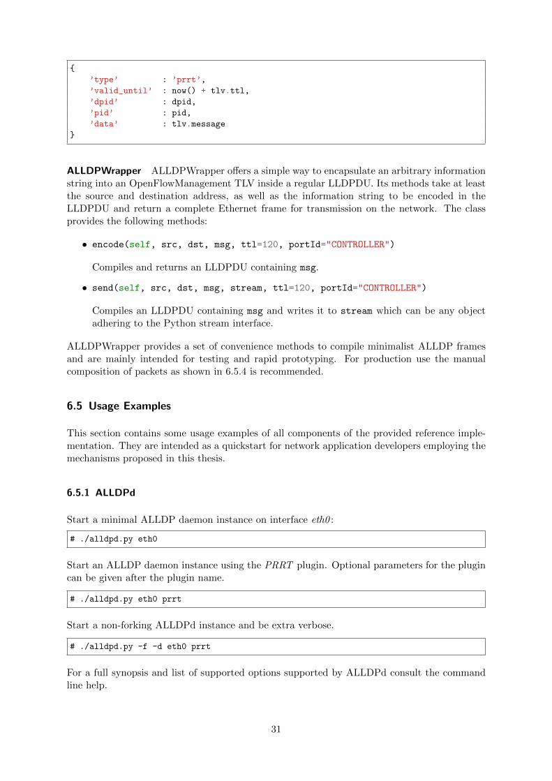
ALLDPWrapper ALLDPWrapper offers a simple way to encapsulate an arbitrary informationstring into an OpenFlowManagement TLV inside a regular LLDPDU. Its methods take at leastthe source and destination address, as well as the information string to be encoded in theLLDPDU and return a complete Ethernet frame for transmission on the network. The classprovides the following methods:
• encode(self, src, dst, msg, ttl=120, portId="CONTROLLER")
Compiles and returns an LLDPDU containing msg.
• send(self, src, dst, msg, stream, ttl=120, portId="CONTROLLER")
Compiles an LLDPDU containing msg and writes it to stream which can be any objectadhering to the Python stream interface.
ALLDPWrapper provides a set of convenience methods to compile minimalist ALLDP framesand are mainly intended for testing and rapid prototyping. For production use the manualcomposition of packets as shown in 6.5.4 is recommended.
6.5 Usage Examples
This section contains some usage examples of all components of the provided reference imple-mentation. They are intended as a quickstart for network application developers employing themechanisms proposed in this thesis.
6.5.1 ALLDPd
Start a minimal ALLDP daemon instance on interface eth0 :
# ./alldpd.py eth0
Start an ALLDP daemon instance using the PRRT plugin. Optional parameters for the plugincan be given after the plugin name.
# ./alldpd.py eth0 prrt
Start a non-forking ALLDPd instance and be extra verbose.
# ./alldpd.py -f -d eth0 prrt
For a full synopsis and list of supported options supported by ALLDPd consult the commandline help.
31
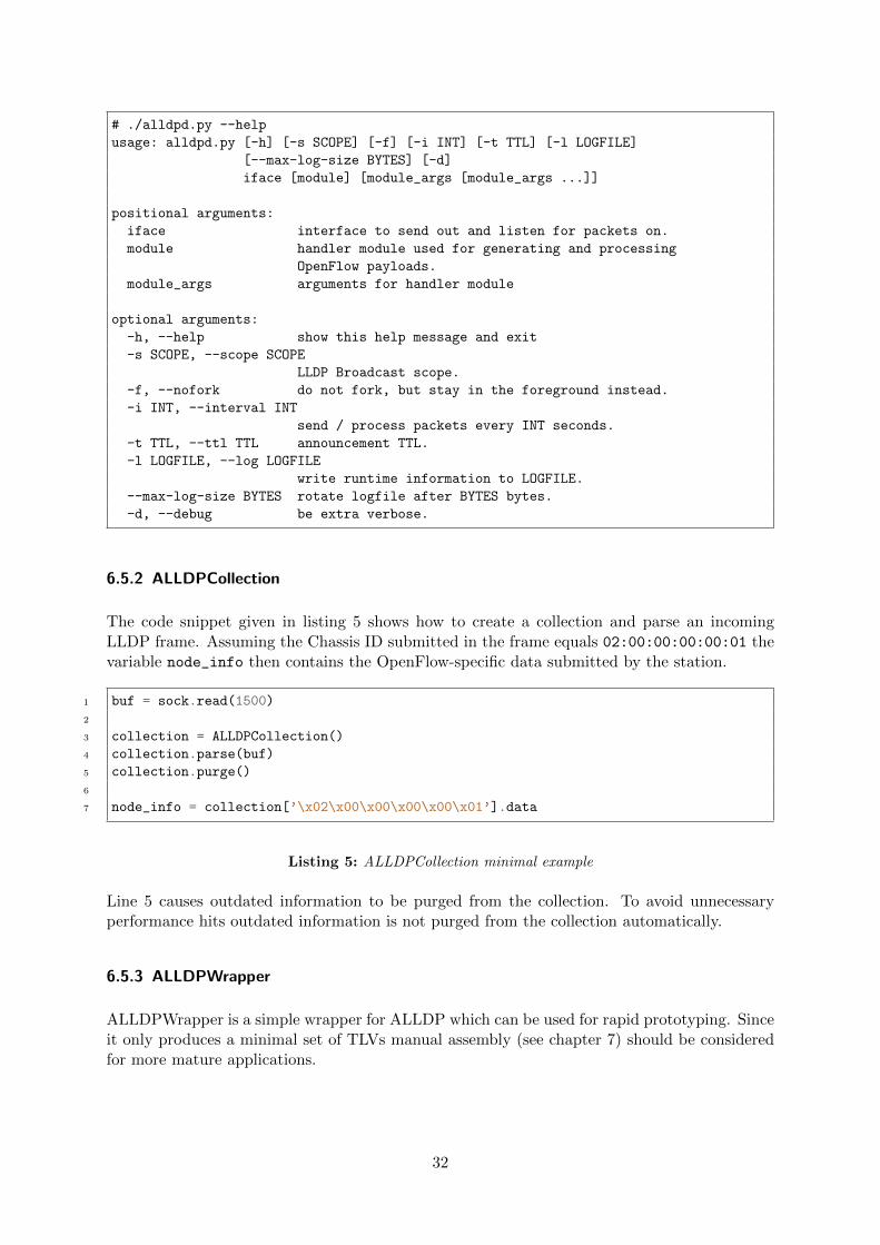
# ./alldpd.py --help
usage: alldpd.py [-h] [-s SCOPE] [-f] [-i INT] [-t TTL] [-l LOGFILE]
[--max-log-size BYTES] [-d]
iface [module] [module_args [module_args ...]]
positional arguments:
iface interface to send out and listen for packets on.
module handler module used for generating and processing
OpenFlow payloads.
module_args arguments for handler module
optional arguments:
-h, --help show this help message and exit
-s SCOPE, --scope SCOPE
LLDP Broadcast scope.
-f, --nofork do not fork, but stay in the foreground instead.
-i INT, --interval INT
send / process packets every INT seconds.
-t TTL, --ttl TTL announcement TTL.
-l LOGFILE, --log LOGFILE
write runtime information to LOGFILE.
--max-log-size BYTES rotate logfile after BYTES bytes.
-d, --debug be extra verbose.
6.5.2 ALLDPCollection
The code snippet given in listing 5 shows how to create a collection and parse an incomingLLDP frame. Assuming the Chassis ID submitted in the frame equals 02:00:00:00:00:01 thevariable node_info then contains the OpenFlow-specific data submitted by the station.
1 buf = sock.read(1500)
2
3 collection = ALLDPCollection()
4 collection.parse(buf)
5 collection.purge()
6
7 node_info = collection[’\x02\x00\x00\x00\x00\x01’].data
Listing 5: ALLDPCollection minimal example
Line 5 causes outdated information to be purged from the collection. To avoid unnecessaryperformance hits outdated information is not purged from the collection automatically.
6.5.3 ALLDPWrapper
ALLDPWrapper is a simple wrapper for ALLDP which can be used for rapid prototyping. Sinceit only produces a minimal set of TLVs manual assembly (see chapter 7) should be consideredfor more mature applications.
32
1 wrap = ALLDPWrapper()
2 frame = wrap.encode(’\x02\x00\x00\x00\x00\x01’, ’\x01\x80\xC2\x00\x00\x0E’,
3 "Hello OpenFlow!")
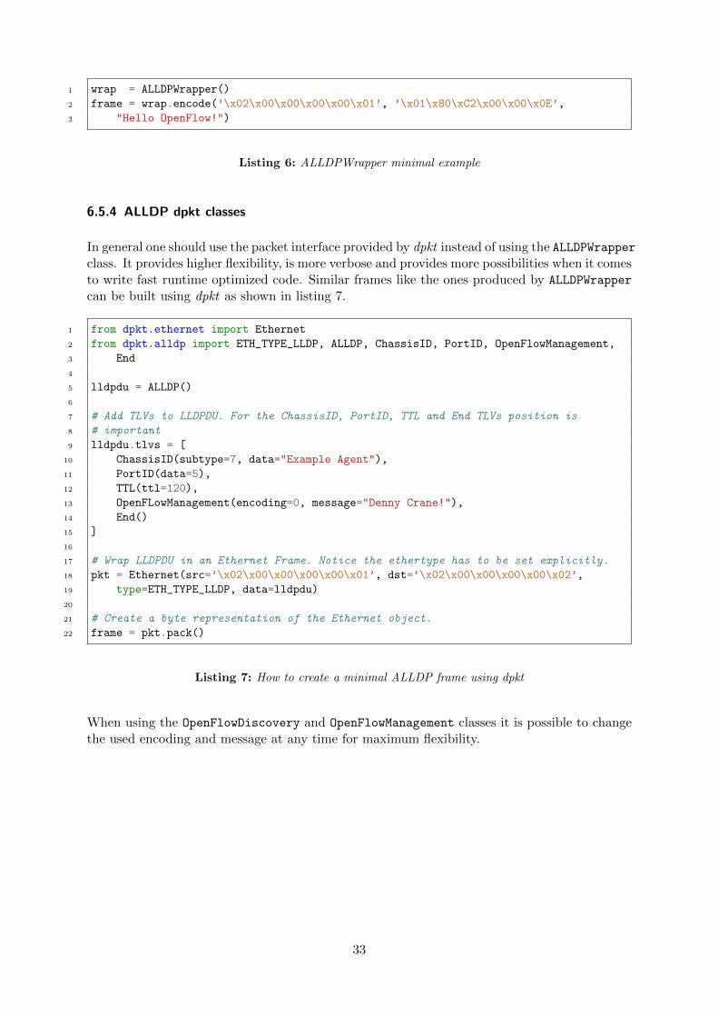
Listing 6: ALLDPWrapper minimal example
6.5.4 ALLDP dpkt classes
In general one should use the packet interface provided by dpkt instead of using the ALLDPWrapperclass. It provides higher flexibility, is more verbose and provides more possibilities when it comesto write fast runtime optimized code. Similar frames like the ones produced by ALLDPWrapper
can be built using dpkt as shown in listing 7.
1 from dpkt.ethernet import Ethernet
2 from dpkt.alldp import ETH_TYPE_LLDP, ALLDP, ChassisID, PortID, OpenFlowManagement,
3 End
4
5 lldpdu = ALLDP()
6
7 # Add TLVs to LLDPDU. For the ChassisID, PortID, TTL and End TLVs position is
8 # important
9 lldpdu.tlvs = [
10 ChassisID(subtype=7, data="Example Agent"),
11 PortID(data=5),
12 TTL(ttl=120),
13 OpenFLowManagement(encoding=0, message="Denny Crane!"),
14 End()
15 ]
16
17 # Wrap LLDPDU in an Ethernet Frame. Notice the ethertype has to be set explicitly.
18 pkt = Ethernet(src=’\x02\x00\x00\x00\x00\x01’, dst=’\x02\x00\x00\x00\x00\x02’,
19 type=ETH_TYPE_LLDP, data=lldpdu)
20
21 # Create a byte representation of the Ethernet object.
22 frame = pkt.pack()
Listing 7: How to create a minimal ALLDP frame using dpkt
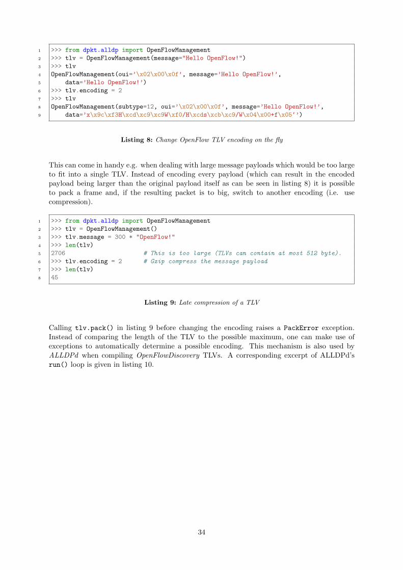
When using the OpenFlowDiscovery and OpenFlowManagement classes it is possible to changethe used encoding and message at any time for maximum flexibility.
33
1 >>> from dpkt.alldp import OpenFlowManagement
2 >>> tlv = OpenFlowManagement(message="Hello OpenFlow!")
3 >>> tlv
4 OpenFlowManagement(oui=’\x02\x00\x0f’, message=’Hello OpenFlow!’,
5 data=’Hello OpenFlow!’)
6 >>> tlv.encoding = 2
7 >>> tlv
8 OpenFlowManagement(subtype=12, oui=’\x02\x00\x0f’, message=’Hello OpenFlow!’,
9 data=’x\x9c\xf3H\xcd\xc9\xc9W\xf0/H\xcds\xcb\xc9/W\x04\x00+f\x05‘’)
Listing 8: Change OpenFlow TLV encoding on the fly
This can come in handy e.g. when dealing with large message payloads which would be too largeto fit into a single TLV. Instead of encoding every payload (which can result in the encodedpayload being larger than the original payload itself as can be seen in listing 8) it is possibleto pack a frame and, if the resulting packet is to big, switch to another encoding (i.e. usecompression).
1 >>> from dpkt.alldp import OpenFlowManagement
2 >>> tlv = OpenFlowManagement()
3 >>> tlv.message = 300 * "OpenFlow!"
4 >>> len(tlv)
5 2706 # This is too large (TLVs can contain at most 512 byte).
6 >>> tlv.encoding = 2 # Gzip compress the message payload
7 >>> len(tlv)
8 45
Listing 9: Late compression of a TLV
Calling tlv.pack() in listing 9 before changing the encoding raises a PackError exception.Instead of comparing the length of the TLV to the possible maximum, one can make use ofexceptions to automatically determine a possible encoding. This mechanism is also used byALLDPd when compiling OpenFlowDiscovery TLVs. A corresponding excerpt of ALLDPd’srun() loop is given in listing 10.
34
1 try:
2 oftlv = lldp.OpenFlowDiscovery(message=payload)
3 # check if the payload fits the TLV with any supported codec
4 for codec in range(10): # for OpenFlowManagement TLVs use range(10,20)
5 try:
6 oftlv.pack()
7 except PackError:
8 # If the message is too big try the next codec
9 try:
10 oftlv.encoding += 1
11 continue
12 except KeyError: # raised if a given subtype is undefined / not implemented
13 # If we run out of codecs we raise a PackError for the outer loop
14 raise PackError
15 else:
16 break
17 except PackError as e:
18 print "Payload too large."
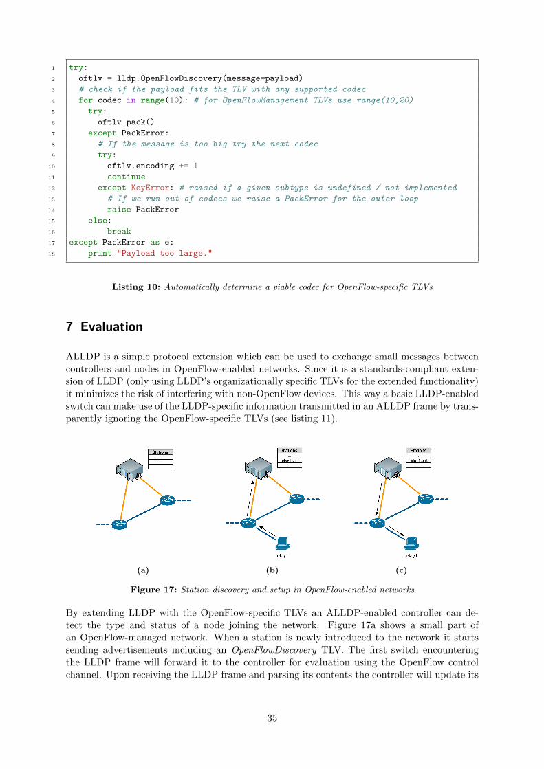
Listing 10: Automatically determine a viable codec for OpenFlow-specific TLVs
7 Evaluation
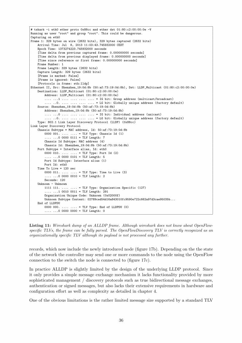
ALLDP is a simple protocol extension which can be used to exchange small messages betweencontrollers and nodes in OpenFlow-enabled networks. Since it is a standards-compliant exten-sion of LLDP (only using LLDP’s organizationally specific TLVs for the extended functionality)it minimizes the risk of interfering with non-OpenFlow devices. This way a basic LLDP-enabledswitch can make use of the LLDP-specific information transmitted in an ALLDP frame by trans-parently ignoring the OpenFlow-specific TLVs (see listing 11).
(a) (b) (c)
Figure 17: Station discovery and setup in OpenFlow-enabled networks
By extending LLDP with the OpenFlow-specific TLVs an ALLDP-enabled controller can de-tect the type and status of a node joining the network. Figure 17a shows a small part ofan OpenFlow-managed network. When a station is newly introduced to the network it startssending advertisements including an OpenFlowDiscovery TLV. The first switch encounteringthe LLDP frame will forward it to the controller for evaluation using the OpenFlow controlchannel. Upon receiving the LLDP frame and parsing its contents the controller will update its
35
# tshark -i eth0 ether proto 0x88cc and ether dst 01:80:c2:00:00:0e -V
Running as user "root" and group "root". This could be dangerous.
Capturing on eth0
Frame 1: 329 bytes on wire (2632 bits), 329 bytes captured (2632 bits)
Arrival Time: Jul 8, 2013 11:03:43.745932000 CEST
Epoch Time: 1373274223.745932000 seconds
[Time delta from previous captured frame: 0.000000000 seconds]
[Time delta from previous displayed frame: 0.000000000 seconds]
[Time since reference or first frame: 0.000000000 seconds]
Frame Number: 1
Frame Length: 329 bytes (2632 bits)
Capture Length: 329 bytes (2632 bits)
[Frame is marked: False]
[Frame is ignored: False]
[Protocols in frame: eth:lldp]
Ethernet II, Src: Shenzhen_19:0d:8b (50:af:73:19:0d:8b), Dst: LLDP_Multicast (01:80:c2:00:00:0e)
Destination: LLDP_Multicast (01:80:c2:00:00:0e)
Address: LLDP_Multicast (01:80:c2:00:00:0e)
.... ...1 .... .... .... .... = IG bit: Group address (multicast/broadcast)
.... ..0. .... .... .... .... = LG bit: Globally unique address (factory default)
Source: Shenzhen_19:0d:8b (50:af:73:19:0d:8b)
Address: Shenzhen_19:0d:8b (50:af:73:19:0d:8b)
.... ...0 .... .... .... .... = IG bit: Individual address (unicast)
.... ..0. .... .... .... .... = LG bit: Globally unique address (factory default)
Type: 802.1 Link Layer Discovery Protocol (LLDP) (0x88cc)
Link Layer Discovery Protocol
Chassis Subtype = MAC address, Id: 50:af:73:19:0d:8b
0000 001. .... .... = TLV Type: Chassis Id (1)
.... ...0 0000 0111 = TLV Length: 7
Chassis Id Subtype: MAC address (4)
Chassis Id: Shenzhen_19:0d:8b (50:af:73:19:0d:8b)
Port Subtype = Interface alias, Id: eth0
0000 010. .... .... = TLV Type: Port Id (2)
.... ...0 0000 0101 = TLV Length: 5
Port Id Subtype: Interface alias (1)
Port Id: eth0
Time To Live = 120 sec
0000 011. .... .... = TLV Type: Time to Live (3)
.... ...0 0000 0010 = TLV Length: 2
Seconds: 120
Unknown - Unknown
1111 111. .... .... = TLV Type: Organization Specific (127)
.... ...1 0010 0011 = TLV Length: 291
Organization Unique Code: Unknown (0x02000f)
Unknown Subtype Content: 02789ced54d16a843010fc9590e722c662a97d3cae95035b...
End of LLDPDU
0000 000. .... .... = TLV Type: End of LLDPDU (0)
.... ...0 0000 0000 = TLV Length: 0
Listing 11: Wireshark dump of an ALLDP frame. Although wireshark does not know about OpenFlow-specific TLVs, the frame can be fully parsed. The OpenFlowDiscovery TLV is correctly recognized as anorganizationally specific TLV although its payload is not processed any further.
records, which now include the newly introduced node (figure 17b). Depending on the the stateof the network the controller may send one or more commands to the node using the OpenFlowconnection to the switch the node is connected to (figure 17c).
In practice ALLDP is slightly limited by the design of the underlying LLDP protocol. Sinceit only provides a simple message exchange mechanism it lacks functionality provided by moresophisticated management / discovery protocols such as true bidirectional message exchanges,authentication or signed messages, but also lacks their extensive requirements in hardware andconfiguration effort as well as complexity as detailed in chapter 4.
One of the obvious limitations is the rather limited message size supported by a standard TLV
36
(512 bytes). By using compression mechanisms the upper bound can be improved on, but, sincethe compression ratio may vary depending on the message contents, messages are neverthelessstill rather limited in size.
In order to outperform these limitations a future implementation of ALLDP might decide todeviate from the LLDP specification to e.g. allow a single message to span more than one TLV(which is not allowed by the LLDP standard definition). In practice this extends the limitposed by a single TLV, but it makes parsing of LLDP data units more cumbersome and doesnot have any influence on the overall limit of 1500 bytes for the LLDP data unit itself. Itmight be better to define special OpenFlow-specific subtypes for well-established applicationsinstead which make use of optimized bit-aligned data packing (as employed by most of theLLDP standard TLVs).
8 Conclusion
The ever-ongoing paradigm shift experienced by today’s networks requires network engineers torethink the way we exchange information. Software Defined Networking, with OpenFlow beingthe most promising architecture at the time of this writing, offers a neat and cost-effective wayto develop and test new operational principles without requiring established equipment vendorsto fully disclose their proprietary platforms.
With global annual IP traffic passing the zettabyte threshold and the number of devices con-nected to IP networks being nearly three times as high as the global population by the end of2016, networks are facing a new challenge [7]. Ease of deployment and configuration of networkcore devices becomes more important each day.
While OpenFlow eases management and operation of network core devices such as routers andswitches, it offers no standardized way to interface with non-crucial, but nevertheless important,devices which can improve network efficiency. Traditional management protocols are generallynot up to the challenge and often introduce additional overhead.
Extending LLDP as a well-established link-layer protocol in a standards-compliant way offersnon-OpenFlow devices a mechanism to introduce themselves to the network (i.e. the controller),while at the same time allowing the network to establish operational ground rules, alleviatingmanagement effort from the network engineer and potentially improving network throughput.
37
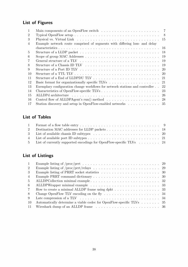
List of Figures
1 Main components of an OpenFlow switch . . . . . . . . . . . . . . . . . . . . . . 72 Typical OpenFlow setup . . . . . . . . . . . . . . . . . . . . . . . . . . . . . . . . 83 Physical vs. Virtual Link . . . . . . . . . . . . . . . . . . . . . . . . . . . . . . . 154 Example network route comprised of segments with differing loss- and delay
characteristics . . . . . . . . . . . . . . . . . . . . . . . . . . . . . . . . . . . . . . 165 Structure of a LLDP packet . . . . . . . . . . . . . . . . . . . . . . . . . . . . . . 186 Scope of group MAC Addresses . . . . . . . . . . . . . . . . . . . . . . . . . . . . 197 General structure of a TLV . . . . . . . . . . . . . . . . . . . . . . . . . . . . . . 198 Structure of a Chassis ID TLV . . . . . . . . . . . . . . . . . . . . . . . . . . . . 199 Structure of a Port ID TLV . . . . . . . . . . . . . . . . . . . . . . . . . . . . . . 2010 Structure of a TTL TLV . . . . . . . . . . . . . . . . . . . . . . . . . . . . . . . . 2011 Structure of a End of LLDPDU TLV . . . . . . . . . . . . . . . . . . . . . . . . . 2112 Basic format for organizationally specific TLVs . . . . . . . . . . . . . . . . . . . 2113 Exemplary configuration change workflows for network stations and controller . . 2214 Characteristics of OpenFlow-specific TLVs . . . . . . . . . . . . . . . . . . . . . . 2315 ALLDPd architecture . . . . . . . . . . . . . . . . . . . . . . . . . . . . . . . . . 2616 Control flow of ALLDPAgent’s run() method . . . . . . . . . . . . . . . . . . . . 2817 Station discovery and setup in OpenFlow-enabled networks . . . . . . . . . . . . 35
List of Tables
1 Format of a flow table entry . . . . . . . . . . . . . . . . . . . . . . . . . . . . . . 92 Destination MAC addresses for LLDP packets . . . . . . . . . . . . . . . . . . . . 183 List of available chassis ID subtypes . . . . . . . . . . . . . . . . . . . . . . . . . 204 List of available port ID subtypes . . . . . . . . . . . . . . . . . . . . . . . . . . . 215 List of currently supported encodings for OpenFlow-specific TLVs . . . . . . . . 24
List of Listings
1 Example listing of /proc/prrt . . . . . . . . . . . . . . . . . . . . . . . . . . . . . 292 Example listing of /proc/prrt/relays . . . . . . . . . . . . . . . . . . . . . . . . . 293 Example listing of PRRT socket statistics . . . . . . . . . . . . . . . . . . . . . . 304 Example PRRT command dictionary . . . . . . . . . . . . . . . . . . . . . . . . . 305 ALLDPCollection minimal example . . . . . . . . . . . . . . . . . . . . . . . . . . 326 ALLDPWrapper minimal example . . . . . . . . . . . . . . . . . . . . . . . . . . 337 How to create a minimal ALLDP frame using dpkt . . . . . . . . . . . . . . . . . 338 Change OpenFlow TLV encoding on the fly . . . . . . . . . . . . . . . . . . . . . 349 Late compression of a TLV . . . . . . . . . . . . . . . . . . . . . . . . . . . . . . 3410 Automatically determine a viable codec for OpenFlow-specific TLVs . . . . . . . 3511 Wireshark dump of an ALLDP frame . . . . . . . . . . . . . . . . . . . . . . . . 36
38
References
[1] IEEE Computer Society, ”Station and Media Access Control Connectivity Discovery”,IEEE Standard for Local and metropolitan area networks, IEEE Std 802.1AB-2009
[2] Open Networking Foundation, ”OpenFlow Switch Specification”, Version 1.3 / Wire Pro-tocol 0x04, June 2012
[3] Open Networking Foundation, ”Software-Defined Networking: The New Norm for Net-works”, ONF Whitepaper, April 2012
[4] George Pallis, Athena Vakali, ”Insight and Perspectives for Content Delivery Networks”,Communications of the ACM / Vol. 49 No.1 / Jan. 06
[5] IEEE Computer Society, ”Media Access Control (MAC) Bridges”, IEEE Standard forLocal and metropolitan area networks, IEEE Std 802.1D-2004
[6] IEEE Computer Society, ”Media Access Control (MAC) Bridges and Virtual Bridge LocalArea Networks”, IEEE Standard for Local and metropolitan area networks, IEEE Std802.1Q-2011
[7] Cisco Systems Inc., ”Cisco Visual Networking Index”, 2012
[8] Manuel Gorius, ”Adaptive Delay-constrained Internet Media Transport”, Dissertation,Telecommunications Lab, Saarland University, 2012
[9] Michael Karl, Manuel Gorius, Thorsten Herfet, ”Routing: Why less intelligence sometimesis more clever”, Telecommunications Lab, Saarland University, 2010
[10] Manuel Gorius, Jochen Miroll, Michael Karl, Thorsten Herfet, ”Predictable Reliabilityand Packet Loss Domain Separation for IP Media Delivery”, Telecommunications Lab /Intel Visual Computing Institute, Saarland University, 2011
[11] Bernd Wittefeld, ”A PRRT Architecture for the OpenFlow Protocol Suite”, Master’sThesis, Telecommunications Lab, Saarland University, 2012
[12] IEEE Computer Society, ”IEEE Standard for Local and Metropolitan Area Networks:Overview and Architecture”, IEEE Std 802-2001
[13] Telecommunications Industry Association, ”Link Layer Discovery Protocol for Media End-point Devices”, ANSI/TIA-1057, April 2006
[14] Natascha Gude, Teemu Koponen, Justin Pettit, Ben Pfaff, Martın Casado, Nick McK-eown, Scott Schenker, ”NOX: Towards an Operating System for Networks”, ACM SIG-COMM Computer Communication Review, Volume 38, Number 3, July 2008
[15] Rosen, E., Viswanathan, A., and R. Callon, ”Multiprotocol Label Switching Architec-ture”, RFC 3031, January 2001.
[16] Nichols, K., Blake, S., Baker, F., and D. Black, ”Definition of the Differentiated ServicesField (DS Field) in the IPv4 and IPv6 Headers”, RFC 2474, December 1998.
39