authors version 2o3) as a top coat on 7ysz tbcs against
TRANSCRIPT

1
Authors Version
EB-PVD alumina (Al2O3) as a top coat on 7YSZ TBCs against CMAS/VA infiltration:
Deposition and reaction mechanisms.
R. Naraparaju, R. P. Pubbysetty, P. Mechnich and U. Schulz
Journal of the European Ceramic Society 38 (2018) 3333-3346
https://doi.org/10.1016/j.jeurceramsoc.2018.03.027

2
EB-PVD alumina (Al2O3) as a top coat on 7YSZ TBCs against CMAS/VA infiltration:
Deposition and reaction mechanisms.
R. Naraparaju, R. P. Pubbysetty, P. Mechnich and U. Schulz
German Aerospace Centre (DLR), Institute of Materials Research, Cologne 51170, Germany
Abstract
Al2O3 was deposited as a top coat on a standard 7YSZ layer (or layers) by means of EB-PVD
technique and the corresponding morphology of the Al2O3/7YSZ coatings was studied in detail. This
multi-layer TBC system was tested against calcium-magnesium-aluminium-silicate (CMAS) recession
by performing infiltration experiments for different time intervals from 5 min to 50 hours at 1250 ºC
using two types of synthetic CMAS compositions and Eyjafjallajökull volcanic ash (VA) from
Iceland. The results show that the studied EB-PVD Al2O3/7YSZ coatings react quickly with CMAS or
VA melt and form crystalline spinel (MgAl2-xFexO4) and anorthite (CaAl2Si2O4) phases. The presence
of Fe-oxide in the CMAS has been found to be key element in influencing the spinel formation which
was proved to be more efficient against CMAS sealing in comparison to the Fe-free CMAS
compositions. Even though a rapid crystallization was assured, shrinkage cracks in the EB-PVD
alumina layer produced during the crystallization heat treatment have proven to be detrimental for the
CMAS/VA infiltration resistance. To overcome these microstructural drawbacks, an additional
alumina deposition method, namely reaction-bonded alumina oxide (RBAO), was applied on top of
EB-PVD Al2O3. RBAO acts as a sacrificial layer forming stable reaction products inhibiting further
infiltration.
1. Introduction
Modern gas turbines for energy and transportation particularly rely on high-temperature thermal
barrier coatings (TBCs) for improved efficiency and power. Typically, TBCs are made up of ~7 wt. %
Y2O3 stabilized ZrO2 (7YSZ) ceramics [1-6]. A combination of porosity and very low thermal
conductivity provides excellent high temperature insulation. TBCs are most commonly used as
insulation material and to improve the durability of engine parts which also leads to an increase in the
engine operating efficiency. The combustion temperatures of gas turbine engines are high enough to
damage turbine blade alloy. Advanced cooling techniques utilize a combination of internal (forced
convection, impingement cooling) and external (film cooling) systems, with the addition of TBCs, to
increase efficiency and life time of different gas turbine engine parts. These TBCs are mainly
deposited by electron beam physical vapor deposition (EB-PVD) or by air plasma spraying (APS) [7].
The EB-PVD top coats have inter-columnar porosity whereas the APS have porosity and cracks
mainly running parallel to the interface. Apart from that, the siliceous minerals (CaO-MgO-Al2O3-
SiO2, commonly named CMAS), which are widely spread in the atmosphere and commonly identified
in sand, runway debris, and volcanic ash, have a substantial effect on aircraft engines[8, 9] . The hot
corrosion attack of these siliceous particles on TBCs eventually leads to premature failure. Since the
infiltration of CMAS melts on standard 7YSZ TBCs brings detrimental effects on the lifetime of the
coatings, many approaches for CMAS arrest have been proposed. Most of the CMAS mitigation
strategies focus on the chemical reactions between the CMAS melt and the TBC to (i) stop the melt by
crystallizing its main constituents (mostly silicates), and (ii) to block the melt by filling the pores and
columnar gaps of the TBC with the new crystalized phases [10-16]. Alpha-alumina has been used as a
CMAS resistant material on top of 7YSZ deposited by means of different deposition techniques[14,
17, 18]. In all cases, the alumina coating thickness achieved was not sufficient to guarantee a slow
growing crystalline reaction layer which assures the protection against CMAS infiltration. There is no
3
available open literature on fabricating a columnar EB-PVD alumina top coat (with higher thickness)
and infiltration tests on EB-PVD alumina coatings using CMAS/ VA. Thus, a better understanding of
CMAS/VA with EB-PVD alumina interaction at high temperature can lead to significant benefits in
the performance and lifetime extension for aero engines. The crystal structure and morphology of EB-
PVD alumina columns entirely depend on process parameters, primarily substrate temperature,
chamber pressure, and deposition rate. It is known from previous experiments and literature that
during alumina evaporation an unstable melt pool and melt spitting is typically observed [19-23].
Therefore, fabricating crystalline EB-PVD alumina coatings is still challenging. The development of
EB-PVD alumina layer as a CMAS resistant coating is discussed in this paper.
2. Experimental
Processing the EB-PVD alumina coatings
100-120 µm thick Al2O3 layers were deposited on the previously coated 150 µm thick 7YSZ TBCs via
EB-PVD process (DLR coater ESPRI). To avoid damage of metallic substrates such as nickel based
super alloys and bond coats during the high temperature infiltration tests for long duration, alumina
substrates of 1 mm thickness were used as a base material to deposit Al2O3/7YSZ TBCs. A parameter
study was conducted for EB-PVD alumina topcoat on 7YSZ and different runs were made and the
resulting morphologies are explained in the section 3 as shown in Figure 1. The EB-PVD process was
carried out by single source evaporation (using high purity Al2O3 ingots from Phoenix coating
resources Inc., Florida, USA) under conventional rotating mode at different temperatures and
pressures for the same rotation speed of 12 rpm and all the process parameters are given in Table 1.
Manufacturing of RBAO on top of EB-PVD alumina/7YSZ TBC
Reaction-bonded aluminum oxide (RBAO) topcoats were fabricated by a simple painting and firing
process [24]. Spray-atomized Al powder (70 vol. %) and α-Al2O3 (30 vol. %) were used as starting
materials for the RBAO processing. Five wt.-% of a soluble polymer (polyvinylpyrolidone) was added
to the powder mixture. The powders were dispersed in isopropanol (30 wt. % solid content) and
homogenized ultrasonically for 5 min. As coated EB-PVD alumina/7YSZ TBCs were cleaned
ultrasonically in deionized water and dried carefully. The green coatings were deposited on the EB-
PVD alumina topcoat TBCs by painting with a hairbrush (Figure. 2a). After drying, the coated
samples were heat treated for 1 h at 1300°C with a heating rate of 10°C/min in isothermal furnace
(Figure2b).
CMAS and Volcanic Ash Compositions
Two different CMAS compositions and one natural volcanic ash collected from Eyjafjallajökull
volcano in Iceland were used for the infiltration studies (see Table 2). Both CMAS powders (CMAS 1
and UCSB CMAS) were artificially synthetized in the laboratory as used in previous studies [8, 25] .
Infiltration Experiments
Infiltration tests were carried out by depositing CMAS or VA on the top of Al2O3/7YSZ TBCs in the
amount of 20 mg/cm2. Infiltration tests were performed at 1250°C for short (5 min) and long durations
(1 h and 10 h). Short term tests were performed in a cyclic furnace with an overall heating rate of 142
K/min, following isothermal exposure at 1250°C for 5 min and air quenching to room temperature.
Long term CMAS/VA infiltration experiments were carried out isothermally in a Netzsch chamber
furnace with a heating rate of 10 K/min.

4
Characterization
A Siemens D5000 diffractometer using Cu-Kα radiation with a secondary graphite monochromator
was used for standard x-ray diffraction analysis (XRD). In-situ high-temperature XRD analyses were
performed in a D8 Advance diffractometer with CuKα radiation and Lynxeye™ detector (Bruker
AXS, Karlsruhe, Germany) using a Pt-strip-heated stage (HTK 16N, Anton-Paar, Graz, Austria). In-
situ high temperature XRD was performed from 900°C to 1200°C in 50°C steps and 30 min holding
times, respectively (Figure. 5). Microstructures of samples were analyzed by scanning electron
microscopy (SEM) (DSM ultra 55, Carl Zeiss NTS, Wetzlar, Germany). Chemical microanalyses were
carried out by energy-dispersive spectroscopy (EDS) (Inca, Oxford Instruments, Abingdon, UK).
3. Results
3.1. Fabrication of EB-PVD Al2O3 on top of 7YSZ TBCs
Figure.1 shows the SEM images of the manufactured alumina layers with respect to their coating
parameters. It was known that in the typical coating temperature range for zirconia-based TBCs (900-
1100°C) alumina undergoes phase transitions. As the melting point of alumina is considerably lower
than that of zirconia, the substrate temperature during alumina evaporation was chosen to be
approximately 890°C. Run 1 with sample temperature 890±5°C, a chamber pressure (6*10-3
mbar)
and with an ingot feed rate of 0.8 mm/min, shows that the morphology comprises irregular and
asymmetrically distributed primary columns (see Figure. 1a). A high evaporation rate was observed
with the beam energy of 65kW and as a result a highly porous coating was obtained with a deposition
rate of 9 µm/min. These coatings were found to be very brittle with relatively low density which
spalled instantaneously. As the desired alumina structure was not achieved in the Run 1, the coating
was removed by grit blasting (corundum particles with 1.35 bar) and substrates were re-used in Run 2
and Run 3.
The evaporation rate was decreased by reducing the beam power to 44 kW keeping the same chamber
pressure as in the case of Run 1. As a result, the sample temperature was reduced by 100°C in Run 2
and a deposition rate of 2.6 µm/min was achieved. These coatings show uniform growth of a columnar
structure (Figure. 1b), but were brittle. Moreover, as shown in Figure 1(b), the transition at the 7YSZ/
alumina layer interface (note that the 7YSZ column tips were broken due to the grit blasting) was not
smooth and the alumina column diameter continuously increases from root to top leading to a reduced
number of columns. This has resulted in larger inter columnar gaps of around 4 µm which is shown as
an inset in Figure 1(b). Run 3 was performed by maintaining the same sample temperature and beam
energy but increasing the chamber pressure to 9*10-3
mbar and a deposition rate of 1.6 µm/min was
achieved. The obtained coatings were of uniform thickness with the desired column density, as shown
in Figure 1(c). Besides that the 7YSZ/alumina interface was found to be smooth and the alumina
nucleation has almost followed the columnar microstructure of 7YSZ, although the nucleation of
alumina took place on the grit blasted surface which is shown in high magnification in Figure 1(e).
The column width has been reduced in comparison to the Run 2 and the shape of the columns
remained uniform throughout the coating thickness which has resulted in reduced inter-columnar gaps.
Run 4 was performed on as coated EB-PVD 7YSZ samples at slightly increased sample temperature
(around 30°C) and same chamber pressure as in Run 3, but the deposition time was increased to 45
minutes to get a thick coating. The deposition rate achieved in this run was found to be 2.4 µm/min.
The main difference between the Run 3 and 4 was the 7YSZ surface condition, the former being grit
blasted and the latter as coated. The coatings show regular growth of columns with less inter-columnar

5
gaps. A uniform thickness with suitable visible density of the coating was achieved. In addition the
7YSZ/ alumina interface was found to be smooth with a perfect transition as shown in Figure 1 (f).
Coatings with 110 µm thick alumina top layers achieved in Run 4 were used for all the further
infiltration tests. No spitting and evaporation problems were detected during the coating process.
Excellent adhesion of alumina on 7YSZ except in Run 1 was observed as expected from the well-
known good compatibility and adhesion between alumina TGO and 7YSZ or alumina substrates and
7YSZ.
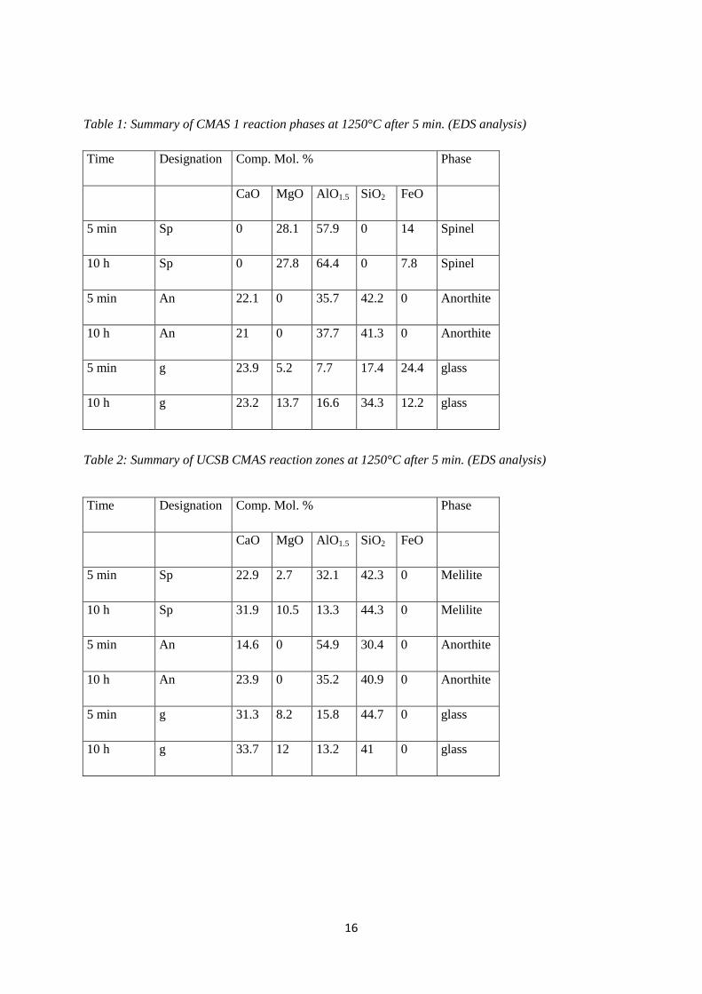
3.2. EB-PVD alumina characterization and phase transition
As coated EB-PVD alumina coatings were amorphous in nature with a little contribution from cubic
gamma phase. It is known from the literature that the phase transition from amorphous to crystalline α-
alumina occurs in the temperature range of 900°C to 1200°C [20, 26, 27]. In situ high temperature
XRD analysis was performed on the alumina layers and the corresponding phase changes are shown in
Figure 3. Changes in α-alumina peak intensities were very low in the temperature range between 900-
1050°C and high intensity sharp peaks were only observed at 1100°C for 30 min. No meta-stable
phases were found in the XRD patterns. Thus, this temperature was taken for further heat treatment of
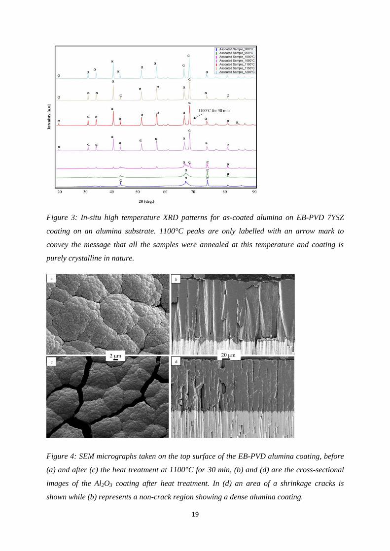
as-coated samples to obtain thermodynamically stable α-alumina topcoats. During the pre-heat
treatment heavy sintering of the alumina coating was observed. SEM surface and cross-sectional
micrographs in Figure 4 show the drastic change in microstructure before and after heat treatment. As-
coated samples at room temperature have a fully dense coating with very thin inter-columnar gaps (see
Figure. 4(a) & (b)). After the heat treatment, as shown in Figure 4 (c) shrinkage cracks have appeared.
In the cross-sectional analysis these cracks are clearly visible in Figure 4(d). In addition, a slight
change in the intra columnar microstructure was also observed after the crystallization treatment as
shown in Figure 4(b) and (d). Alumina columns were found to be more porous after pre-heating than
after as coated which is assumed to be due to the crystallization of amorphous alumina. The columns
were also found to be shrinked after the heat treatment. The interface adhesion was found to be
unaffected by the heat treatment as can be seen in Figure 4(b) and (d). No cracks or delamination were
observed at the interface and the adhesion between 7YSZ layer and alumina was found to be un-
effected by the sintering process.
3.3. CMAS/VA Infiltration Tests
Phase formation of α-Al2O3 and CMAS/VA powder mixtures
Al2O3 is expected to react firmly with all the CMAS/VA variants and to form new crystalline phases.
Alumina powder was mechanically removed from the coatings and used for phase identification. In
order to identify all potential reaction products, powder mixtures consisting of 60 wt. % of CMAS/VA
and 40 wt. % of alumina were prepared (uniformly mixed in a mortar) and isothermally heat treated at
1250°C for 10 h, respectively. Figure. 5 shows the XRD pattern of the alumina/CMAS/VA powder
mixture. Two main common crystal phases are identified as anorthite (CaAl2Si2O8) (An) and (Mg, Al,
Fe)-spinel Mg(Al2-xFex)O4 (Sp). These phases i.e., anorthite (An) and spinel (Sp) exhibit CMAS
sealing property for alumina coatings. Anorthite (An) exhibits the highest peak intensity for UCSB
CMAS, followed by CMAS 1 and Iceland ash. The second common phase, identified as spinel (Sp),
exists in CMAS 1 and Iceland ash. In UCSB CMAS/alumina mixture, an additional phase is identified
as melilite (Me, (Ca2(Mg0.25 Al0.75) (Si1.25 Al0.75 O7)) which might be left over CMAS glass. In the case
of Iceland ash, pseudobrookite (Ps, (Fe2TiO5)) containing Fe and Ti was identified.
Short Term Infiltration
6
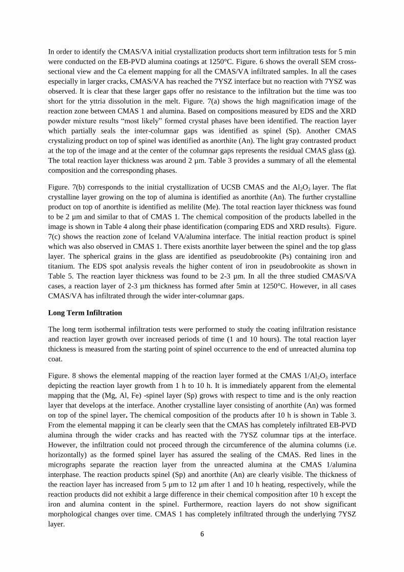
In order to identify the CMAS/VA initial crystallization products short term infiltration tests for 5 min
were conducted on the EB-PVD alumina coatings at 1250°C. Figure. 6 shows the overall SEM cross-
sectional view and the Ca element mapping for all the CMAS/VA infiltrated samples. In all the cases
especially in larger cracks, CMAS/VA has reached the 7YSZ interface but no reaction with 7YSZ was
observed. It is clear that these larger gaps offer no resistance to the infiltration but the time was too
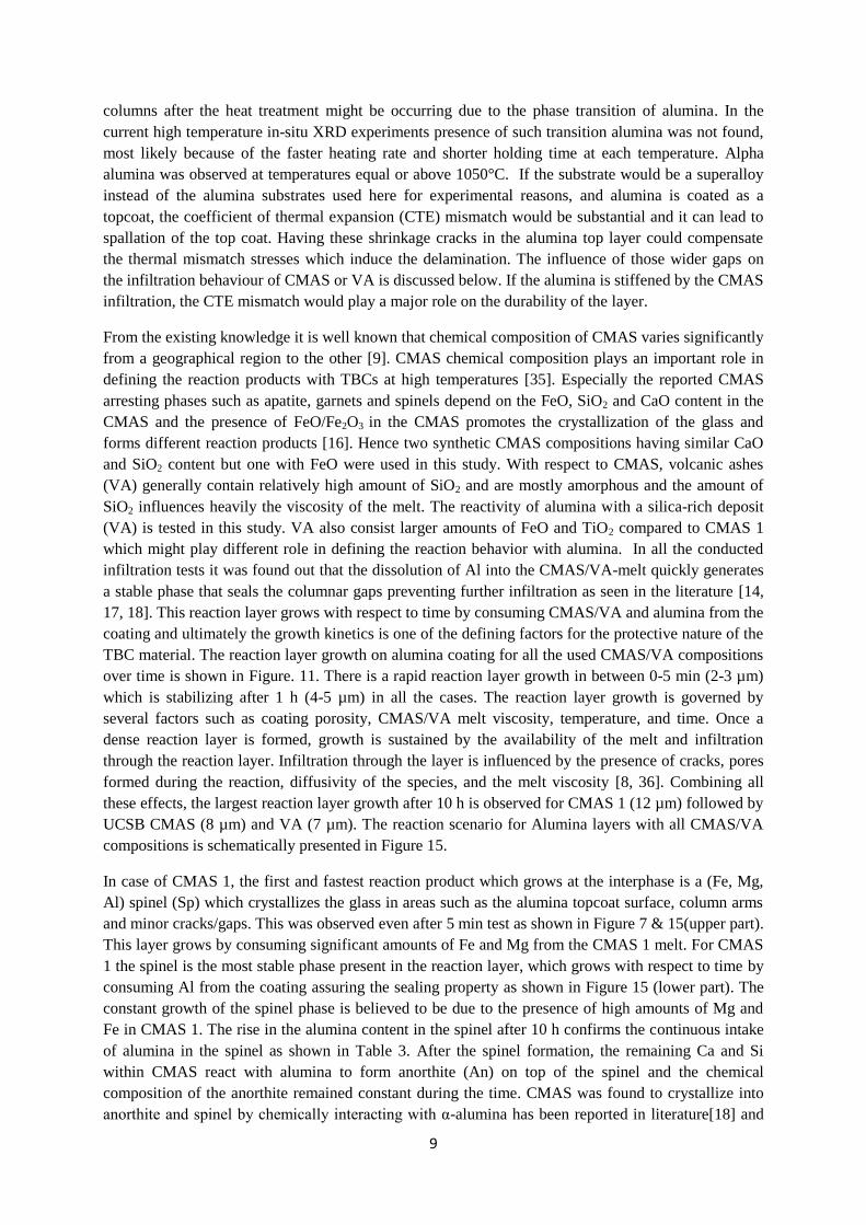
short for the yttria dissolution in the melt. Figure. 7(a) shows the high magnification image of the
reaction zone between CMAS 1 and alumina. Based on compositions measured by EDS and the XRD
powder mixture results “most likely” formed crystal phases have been identified. The reaction layer
which partially seals the inter-columnar gaps was identified as spinel (Sp). Another CMAS
crystalizing product on top of spinel was identified as anorthite (An). The light gray contrasted product
at the top of the image and at the center of the columnar gaps represents the residual CMAS glass (g).
The total reaction layer thickness was around 2 µm. Table 3 provides a summary of all the elemental
composition and the corresponding phases.
Figure. 7(b) corresponds to the initial crystallization of UCSB CMAS and the Al2O3 layer. The flat
crystalline layer growing on the top of alumina is identified as anorthite (An). The further crystalline
product on top of anorthite is identified as melilite (Me). The total reaction layer thickness was found
to be 2 µm and similar to that of CMAS 1. The chemical composition of the products labelled in the
image is shown in Table 4 along their phase identification (comparing EDS and XRD results). Figure.
7(c) shows the reaction zone of Iceland VA/alumina interface. The initial reaction product is spinel
which was also observed in CMAS 1. There exists anorthite layer between the spinel and the top glass
layer. The spherical grains in the glass are identified as pseudobrookite (Ps) containing iron and
titanium. The EDS spot analysis reveals the higher content of iron in pseudobrookite as shown in
Table 5. The reaction layer thickness was found to be 2-3 µm. In all the three studied CMAS/VA
cases, a reaction layer of 2-3 µm thickness has formed after 5min at 1250°C. However, in all cases
CMAS/VA has infiltrated through the wider inter-columnar gaps.
Long Term Infiltration
The long term isothermal infiltration tests were performed to study the coating infiltration resistance
and reaction layer growth over increased periods of time (1 and 10 hours). The total reaction layer
thickness is measured from the starting point of spinel occurrence to the end of unreacted alumina top
coat.
Figure. 8 shows the elemental mapping of the reaction layer formed at the CMAS 1/Al2O3 interface
depicting the reaction layer growth from 1 h to 10 h. It is immediately apparent from the elemental
mapping that the (Mg, Al, Fe) -spinel layer (Sp) grows with respect to time and is the only reaction
layer that develops at the interface. Another crystalline layer consisting of anorthite (An) was formed
on top of the spinel layer. The chemical composition of the products after 10 h is shown in Table 3.
From the elemental mapping it can be clearly seen that the CMAS has completely infiltrated EB-PVD
alumina through the wider cracks and has reacted with the 7YSZ columnar tips at the interface.
However, the infiltration could not proceed through the circumference of the alumina columns (i.e.
horizontally) as the formed spinel layer has assured the sealing of the CMAS. Red lines in the
micrographs separate the reaction layer from the unreacted alumina at the CMAS 1/alumina
interphase. The reaction products spinel (Sp) and anorthite (An) are clearly visible. The thickness of
the reaction layer has increased from 5 µm to 12 µm after 1 and 10 h heating, respectively, while the
reaction products did not exhibit a large difference in their chemical composition after 10 h except the
iron and alumina content in the spinel. Furthermore, reaction layers do not show significant
morphological changes over time. CMAS 1 has completely infiltrated through the underlying 7YSZ
layer.

7
Figure. 9 shows the reaction layer growth on top of the UCSB CMAS/alumina interface after 1 h. and
10 h. of isothermal heating at 1250°C. From the elemental mapping, it is observed that the infiltration
effect is larger compared to CMAS 1 where not only wide cracks were infiltrated but also infiltration
was strong along the circumference of the columns (i.e. in the horizontal direction). The CMAS has
also infiltrated completely through the 7YSZ columns. Anorthite was formed next to the alumina
layer, melilite has formed on top of anorthite and the residual CMAS glass stayed on top of the
melilite. Table 4 provides a summary of all the elemental composition and the corresponding phases
after 10 h. The influence of those wider gaps on the infiltration behaviour of CMAS or VA is
discussed below. No spinel formation at the interface was observed (Absence of Fe, Mg enrichment at
the interface).The formed reaction products have undergone a minor change in their chemical
composition with respect to time and a significant growth of the reaction layer with an increase in the
thickness from 5 µm to 8 µm after 1 h and 10 h was observed. Figure. 10 shows the infiltration
scenario with the respective elemental mapping after 1 h and 10 h of the VA at 1250°C. A uniform
(Mg,Al,Fe)-spinel layer was formed on top of the alumina coating followed by a thin anorthite layer.
The VA ash has completely infiltrated the EB-PVD alumina via cracks and underlying 7YSZ layer
through the inter-columnar gaps. However, the severity of its attack was less compared to the UCSB
CMAS. An increase of the reaction layer thickness from 3 µm to 7 µm was observed after 1 h and 10
h, respectively. Large iron and titanium rich pseudobrookite crystals (Ps) were observed on the top of
spinel layer. Pseudobrookite crystals significantly grow over time and the corresponding chemical
compositional change of Fe and Ti is presented in Table 5. The residual CMAS glass remains present
on top of all the layers in both the short and long term isothermal tests. Reaction layer growth of
alumina with all the CMAS/VA with respect to time is drawn in Figure 11.
3.4. CMAS Infiltration Tests on RBAO Alumina/7YSZ
In the previous sections it was noticed that the EB-PVD alumina exhibits a high reactivity with
CMAS/VA and rapidly forms CMAS arresting products. However, sinter cracks that had been
developed during the pre-heat treatment have allowed the CMAS/VA to locally fully infiltrate. To
overcome the microstructural shrinkage effects, a further alumina layer was applied by means of the
RBAO method. Alpha-Al2O3 was created during the application process itself because of the heat
treatment at 1300°C. Figure. 12 shows the 20-25 µm thick RBAO layer on top of EB-PVD alumina.
The microstructure with no macroscopic crack formation or RBAO coating - alumina topcoat de-
bonding was obtained during the process. For a preliminary assessment, CMAS 1 has been tested on
RBAO/EB-PVD-alumina/7YSZ for 10 h, 20 h, and 50 h at 1250°C. The corresponding EDS mappings
of calcium are shown in Figure. 13. No infiltration within the EB-PVD columnar gaps was found even
after 50 h of testing and the top RBAO has sealed the coating against CMAS 1. The main crystalline
phase which blocks the CMAS infiltration is the dense (Mg, Al, Fe)-spinel layer (Sp) formed on top of
EB-PVD alumina after 50h is shown in Figure 14. The other phase was found to be anorthite (An) as
observed in all the other cases in this study. As time progresses, a growth of the reaction layer was
observed and the total RBAO layer with initial thickness of 20-25 µm was eventually consumed
during the reaction process. Since the final reaction layer thickness was found to be 36 µm after 10 h,
39 µm for 20 h, and 44 µm after 50 h of isothermal heating, the reaction layer originating from EB-
PVD alumina was growing by about 12-20 µm in the time span of 10 and 50 h, but it was still
protective.
4. Discussion
Alumina has been widely recognized as a sacrificial top-coating for YSZ TBC due to its ability to shift
the CMAS composition in order to promote crystallization and blocking further CMAS melt
infiltration[14, 17, 18]. However, the deposition of Al2O3 via EB-PVD technique has been an issue of

8
concern. The morphology of an EB-PVD columnar microstructure strongly depends on the process
parameters [6, 23, 28-30] such as source material, deposition rate, pressure, part rotation speed,
temperature and so on. Moreover, the coating morphology is a function of the melting point of the
coating material and the temperature of the substrate material being coated. In Run 1, although the
used substrate temperature and beam powers were in the range of typical yttria-zirconia system, a
higher evaporation rate was observed which has resulted in a porous brittle coating. From the literature
it is known that in the case of 7YSZ, a higher temperature leads to a higher density of the coating and
the higher pressure causes lower density [31, 32]. Such kind of data was not available for the alumina
deposition and to reduce the alumina evaporation rate and to achieve a more suitable coating quality,
the beam power was reduced to 44 kW and the substrate temperature to 790°C in Run 2. A dense
coating was achieved but the rough 7YSZ surface (grit blasted) has played a major role in the
nucleation of the alumina layer and the shape of the alumina columns. It is well known that the surface
finish of the substrate plays a significant role in defining the microstructure of EB-PVD columns. On a
polished bond coat surface the columnar growth of 7YSZ was found to be uniform and dense whereas
grit blasted surfaces had resulted in porous and non-uniform coatings[32]. In another study it was
shown that a grit blasted EB-PVD 7YSZ surface has experienced a slight disruption of the columnar
growth upon re-deposition whereas a polished surface has a fine grained zone with subsequent
coarsening of the columns [33]. In contrary, the initial nucleation of alumina was found to be not
following the underlying 7YSZ columns in Run 2. It is expected that by increasing the chamber
pressure the density of the coating should decrease at the lower substrate temperatures which might
result in different columnar microstructure. Run 3 was performed with a slightly high chamber
pressure and consequently a variation in the alumina columnar microstructure was observed. Thin and
uniform columns with almost smooth transition from the 7YSZ layer were obtained (Figure. 1f). The
drop in the deposition rate (from 2.6 to 1.6 µm/min), however, contradicts the general tendency where
higher deposition rate is obtained with higher pressure (in case of EB-PVD 7YSZ) as discussed in the
literature [31, 33]. This heterogeneity effect can be attributed to the entirely different evaporation
behavior of alumina and the role of 7YSZ surface roughness. A slight increase in the substrate
temperature facilitated the higher deposition rate in Run 4 where the ability for diffusion of condensed
particles got increased. Even though 30°C rise might be considered as very small, having the 100°C
operational window for alumina deposition this rise could influence the deposition rate considerably.
In addition, run 4 was much longer than all other runs and the final columnar microstructure needs
some time to get established. Consequently, coating density may vary along the thickness, and
variations in alumina thickness may than translate into density variations and hence into a different
deposition rate. The as coated EB-PVD 7YSZ surface with its pyramidal shaped column tips has not
shown a big influence on the final microstructure of EB-PVD alumina columns. The transition at the
interface was slightly better than that of a grit blasted interface. In run 3, i.e. the surface roughness
plays an important role on the nucleation of the columns but at the same time temperature and pressure
can compensate that effect with advancing coating thickness. Having known that in the used
temperature ranges alumina could only be coated as an amorphous layer, a higher deposition
temperature could not be applied due to the so far explained reasons. As a consequence an additional
crystallization treatment was inevitable and a pre-heat treatment was conducted at 1100°C. The
annealing resulted in the desired alpha alumina phase but produced at the same time unfavourable
shrinkage cracks in a mud-type crack arrangement, similarly to previous observations [21]. It is well
known that the alumina undergoes phase transitions from highly disordered cubic close packed
transition gamma alumina lattice to more ordered cubic close packed theta alumina to the final
hexagonal close packed alpha alumina lattice at high temperatures. This alpha alumina phase
transitions occurs by nucleation and growth which results in large spacing between nucleation events
and formation of micrometer scale pore channels [34]. Comparatively higher porosity in the alumina
9
columns after the heat treatment might be occurring due to the phase transition of alumina. In the
current high temperature in-situ XRD experiments presence of such transition alumina was not found,
most likely because of the faster heating rate and shorter holding time at each temperature. Alpha
alumina was observed at temperatures equal or above 1050°C. If the substrate would be a superalloy
instead of the alumina substrates used here for experimental reasons, and alumina is coated as a
topcoat, the coefficient of thermal expansion (CTE) mismatch would be substantial and it can lead to
spallation of the top coat. Having these shrinkage cracks in the alumina top layer could compensate
the thermal mismatch stresses which induce the delamination. The influence of those wider gaps on
the infiltration behaviour of CMAS or VA is discussed below. If the alumina is stiffened by the CMAS
infiltration, the CTE mismatch would play a major role on the durability of the layer.
From the existing knowledge it is well known that chemical composition of CMAS varies significantly
from a geographical region to the other [9]. CMAS chemical composition plays an important role in
defining the reaction products with TBCs at high temperatures [35]. Especially the reported CMAS
arresting phases such as apatite, garnets and spinels depend on the FeO, SiO2 and CaO content in the
CMAS and the presence of FeO/Fe2O3 in the CMAS promotes the crystallization of the glass and
forms different reaction products [16]. Hence two synthetic CMAS compositions having similar CaO
and SiO2 content but one with FeO were used in this study. With respect to CMAS, volcanic ashes
(VA) generally contain relatively high amount of SiO2 and are mostly amorphous and the amount of
SiO2 influences heavily the viscosity of the melt. The reactivity of alumina with a silica-rich deposit
(VA) is tested in this study. VA also consist larger amounts of FeO and TiO2 compared to CMAS 1
which might play different role in defining the reaction behavior with alumina. In all the conducted
infiltration tests it was found out that the dissolution of Al into the CMAS/VA-melt quickly generates
a stable phase that seals the columnar gaps preventing further infiltration as seen in the literature [14,
17, 18]. This reaction layer grows with respect to time by consuming CMAS/VA and alumina from the
coating and ultimately the growth kinetics is one of the defining factors for the protective nature of the
TBC material. The reaction layer growth on alumina coating for all the used CMAS/VA compositions
over time is shown in Figure. 11. There is a rapid reaction layer growth in between 0-5 min (2-3 µm)
which is stabilizing after 1 h (4-5 µm) in all the cases. The reaction layer growth is governed by
several factors such as coating porosity, CMAS/VA melt viscosity, temperature, and time. Once a
dense reaction layer is formed, growth is sustained by the availability of the melt and infiltration
through the reaction layer. Infiltration through the layer is influenced by the presence of cracks, pores
formed during the reaction, diffusivity of the species, and the melt viscosity [8, 36]. Combining all
these effects, the largest reaction layer growth after 10 h is observed for CMAS 1 (12 µm) followed by
UCSB CMAS (8 µm) and VA (7 µm). The reaction scenario for Alumina layers with all CMAS/VA
compositions is schematically presented in Figure 15.
In case of CMAS 1, the first and fastest reaction product which grows at the interphase is a (Fe, Mg,
Al) spinel (Sp) which crystallizes the glass in areas such as the alumina topcoat surface, column arms
and minor cracks/gaps. This was observed even after 5 min test as shown in Figure 7 & 15(upper part).
This layer grows by consuming significant amounts of Fe and Mg from the CMAS 1 melt. For CMAS
1 the spinel is the most stable phase present in the reaction layer, which grows with respect to time by
consuming Al from the coating assuring the sealing property as shown in Figure 15 (lower part). The
constant growth of the spinel phase is believed to be due to the presence of high amounts of Mg and
Fe in CMAS 1. The rise in the alumina content in the spinel after 10 h confirms the continuous intake
of alumina in the spinel as shown in Table 3. After the spinel formation, the remaining Ca and Si
within CMAS react with alumina to form anorthite (An) on top of the spinel and the chemical
composition of the anorthite remained constant during the time. CMAS was found to crystallize into
anorthite and spinel by chemically interacting with α-alumina has been reported in literature[18] and

10
was found in the present powder mixture annealing experiments as well. The anorthite phase is known
for its stability which was reported to provide sealing properties[17]. However, in the present case the
anorthite phase was only found on top of the reaction layer as a secondary reaction product without
sealing capability since a large reservoir of melt is still available. EB-PVD Al2O3 coatings exhibited
cracks and gaps after the crystallization heat treatment. The wide gaps could be easily penetrated by all
deposits, act as a reduced barrier for the penetration of the CMAS melt and this behavior was observed
immediately after 5 mins. However, due to the very short time the reaction products did not evolve
uniformly within the cracks. After few hours of infiltration time, the CMAS 1 has penetrated the
whole alumina layer and the 7YSZ layer. A clear distinction between the reaction products within the
cracks could be observed. A spinel layer has formed at the boundaries of the cracks and an anorthite
layer next to it followed by the rest glass similar to the surface reaction. The infiltrated CMAS 1 has
reacted with the 7YSZ columnar tips and the feather arms, while dissolution of yttria causes
destabilization of tetragonal zirconia which is illustrated in Figure 15 as discussed in the literature [8,
15]. Wherever these cracks were not present the formed spinel layer has sealed the CMAS infiltration
and that clearly shows the protective nature of spinel layer.
UCSB CMAS forms anorthite (An) as a reaction product directly on top of alumina as well as in the
cracks even after 5 mins. As seen in the Figure 6 and 15, the cracks were used as free paths by the
CMAS and as the infiltration time has progressed the reaction scenario became clear and an increase
in the anorthite layer thickness was observed. Infiltration has progressed through the cracks up to the
7YSZ interface and also through the whole 7YSZ layer. However, the anorthite layer which was
formed on the alumina surface was not as protective as the spinel layer as in the case of CMAS 1. The
excess infiltration in addition to the cracks in the alumina layer as observed in Figure 9, supports the
idea that anorthite could not form uniformly at the CMAS/alumina interface and the molten glass was
using these gaps to infiltrate. The other crystalline product melilite (Me) which was formed discretely
as a byproduct on top of anorthite consists all the elements that CMAS glass has and probably cannot
provide protective sealing effect. The magnesia content in the melilite phase has increased
substantially after 10 h as shown in Table 4 and the anorthite phase has been stabilized. The absence
of Fe in UCSB CMAS does not provide enhanced spinel formation and the magnesia has been
segregated in to melilite with the remaining glass; as a result alumina could not be sealed by a
protective spinel layer restricting the infiltration. Another interesting observation was the growth of
anorthite crystals within the cracks. These crystals were almost sealing the cracks with smaller glass
pockets inside as shown in Figure 9 and 15 (lower part). The reason for this behavior could be due to a
slow reaction rate and anorthite phase needs longer annealing times. i.e. once the whole alumina and
7YSZ layers were infiltrated the glass accumulated within the cracks has accommodated the
continuous alumina supply from the coating and crystalized into a thick anorthite. From the results it
can be concluded that Fe is a key element enhancing crystallization of the spinel phase. As a
consequence UCSB CMAS has infiltrated through the circumference of the columns (i.e., thicker
deposits of Ca, Si compared to the CMAS1/VA) along with the infiltration within the inter-columnar
gaps up to the underneath 7YSZ layer. Presence of globular particles at the 7YSZ interface proves that
the 7YSZ layer has undergone reaction with the UCSB CMAS similar to the CMAS 1 case.
In the case of VA, the reaction has proceeded with a quick formation of spinel generating an initial
sealing against the melt after 5 mins as shown in Figure 7 and 15 (upper part). A thin anorthite layer
was formed on top of the spinel layer similar to that of CMAS 1. In contrast to the CMAS 1, VA has
formed an additional phase pseudobrookite within the cracks as well as in the left over glass on top.
The growth rate of the spinel layer is relatively slow, when compared to CMAS 1. Two reasons may
explain this observation: First, the viscosity of VA is higher in comparison with CMAS 1 [16].
Second, Fe and Ti which were present in higher amounts (around 2 times) in VA were partially

11
consumed by the other crystalline phase pseudobrookite (Ps). This effect can be witnessed by the
increase in the pseudobrookite crystal size after 10 h (Figure 10 and 15). A noticeable change in
chemical composition of pseudobrookite with respect to time has been observed. An increase in Ti and
a decrease in Fe content was seen (see Table 5), where the Fe content from glass acts as a sink for
stabilizing spinel layer on top from 1h to 10 h. It is clear that the pseudobrookite phase did not involve
alumina and therefore its crystallization was a product of the changes in chemistry as the reaction with
alumina proceeds. This may not play a major role in the melt arrest mechanism. The noticeable
difference in the spinel composition of the VA case (higher iron oxide to alumina ratio compared to
CMAS 1) confirms that FeO has a preference to stabilize the spinel layer and promotes its formation.
Infiltration has proceeded to the 7YSZ layer with respect to the time and the reaction was similar to
the other cases.
The pure chemical criterion for the selection of TBCs that are resistant to CMAS/VA attack having a
quick reaction followed by the crystallization of the melt is not sufficient when it comes to a real
coating. The coating microstructure plays an equal and important role and this fact is proven in this
study as the EB-PVD alumina offers little resistance to the infiltration due to its microstructural
effects. As an alternative, new approach a RBAO top-coat was applied on EB-PVD alumina to
diminish detrimental effects of the shrinkage cracks. An important benefit of the RBAO
manufacturing process is the oxidation-induced volume expansion of Al, which reduces or even fully
compensates sintering related shrinkage of the underlying EB-PVD alumina and finally prevents
coating crack formation [24]. RBAO has formed same CMAS arresting products with the CMAS 1 as
in case of EB-PVD alumina layer as expected. The main difference between EB-PVD and RBAO
alumina coatings is its microstructure where RBAO offers high surface area of pores which are
distributed uniformly over the surface compared to the inter columnar gaps (and shrinkage cracks) in
case of EB-PVD. This allows the CMAS 1 to readily infiltrate more rapidly and react uniformly and
form a quick sealing spinel layer. The RBAO top-coat was being uniformly infiltrated (see Figure 13)
initially but by that time it has also rapidly reacted with CMAS melt and induced spinel crystallization.
From the literature it is known that the most efficient TBC coating in arresting CMAS was
Gadolinium zirconate and it has formed a reaction layer of 30 µm when it is subjected to a heat
treatment for 4 h at 1300°C [12, 37]. In comparison, a maximum infiltration depth of 41 µm was
observed after 50 h at 1250°C in RBAO/EB-PVD alumina against CMAS in this study. No CMAS
further infiltration into the underlying 7YSZ layer was observed. This clearly states that the RBAO is
probably another reliable processing method/material for CMAS mitigation. Currently ongoing
research concentrates on (i) reducing the manufacturing temperature of the RBAO in order to avoid
the expected damage to the underlying metal when using the currently applied 1300°C, (ii) increasing
the RBAO thickness, and (iii) applying it directly on the 7YSZ TBC. In the future an assessment of
performance and the spallation behavior of such sacrificial RBAO top-coats have to be made by
performing furnace cycle and thermal cycling tests.
5. Conclusions
Al2O3 has been successfully deposited on top of 7YSZ using EB-PVD with a favourable columnar
morphology. As the as-coated alumina is amorphous an additional heat treatment was needed to
establish the stable alpha alumina phase. The following conclusions can be made based on this study.
1. Substrate temperature and the chamber pressure have a great influence on the EB-PVD
alumina columnar microstructure, especially on the inter-columnar porosity and the column
thickness. A rough 7YSZ surface influences the nucleation of alumina layer at the interface
and the growth of columns. Selection of right temperature and the pressure can counterpart the
rough surface and control the alumina nucleation to have a smoother interface.
12
2. Alumina coatings exhibited good CMAS/VA resistance by forming melt arresting products
(i.e., spinel (MgAl2-xFexO4 and anorthite (CaAl2Si2O8)). The reaction products seal smaller
gaps against infiltration and generate a uniform reaction layer at the TBC/melt interface which
exhibited a minimal growth with time. However, the melt infiltration could not be mitigated in
larger cracks that are formed due to the crystallization of the amorphous alumina coatings.
3. The Fe content in CMAS/VA plays a significant role in forming a (Mg, Al, Fe)-spinel acting
as major sealing phase. In the case of CMAS 1 and Iceland VA which contain high amounts of
Fe, the diffusion of Al into the Fe rich glass exhibits a higher activity in generating spinel
whereas the absence of Fe in UCSB CMAS prevented the formation of spinel.
4. Additional reaction-bonded alumina (RBAO) top-coats provide a favourable porosity network
and rapidly react with CMAS, finally completely preventing melt infiltration into the TBC.
Therefore, RBAO is considered a potential sacrificial top coat for mitigating TBC damage by
deposits.
Acknowledgments:
The authors express their gratitude to D. Peters and J. Brien for manufacture of TBCs, as well as A.
Handwerk for providing technical support for thermal test implementation. Additionally, the authors
thank J Gomez Chavez for his assistance in critical input and discussions related to the project. The
authors thank the German Science Foundation (DFG) for funding this project (Nr: SCHU 1372/5-1).
References:
1. D. R. Clarke, M. Oechsner, and N. P. Padture, 'Thermal-barrier coatings for more efficient
gas-turbine engines', MRS bulletin 37 (10) (2012) 891-898.
2. X. Q. Cao, R. Vassen, and D. Stoever, 'Ceramic materials for thermal barrier coatings', Journal
of the European Ceramic Society 24 (2004) 1-10.
3. R. Darolia, 'Thermal barrier coatings technology: critical review, progress update, remaining
challenges and prospects', International Materials Reviews 58 (2013) 315-348.
4. C. G. Levi, 'Emerging materials and processes for thermal barrier systems', Current Opinion in
Solid State and Materials Science 8 (1) (2004) 77-91.
5. R. A. Miller, 'Thermal barrier coatings for aircraft engines: history and directions', Journal of
Thermal Spray Technology 6 (1) (1997) 35-42.
6. A. F. Renteria, B. Saruhan, U. Schulz, H. J. Raetzer-Scheibe, J. Haug, and A. Wiedenmann,
'Effect of morphology on thermal conductivity of EB-PVD PYSZ TBCs', Surface and Coatings
Technology 201 (2006) 2611-2620.
7. S. Sampath, U. Schulz, M. O. Jarligo, and S. Kuroda, 'Processing science of advanced
thermal-barrier systems', MRS Bulletin 37 (2012) 903-910.
8. R. Naraparaju, U. Schulz, P. Mechnich, P. Döbber, and F. Seidel, 'Degradation study of 7wt.%
yttria stabilised zirconia (7YSZ) thermal barrier coatings on aero-engine combustion chamber parts
due to infiltration by different CaO-MgO-Al2O3-SiO2 variants', Surface and Coatings Technology 260
(2014) 73-81.

13
9. C. G. Levi, J. W. Hutchinson, M.-H. Vidal-Sétif, and C. A. Johnson, 'Environmental
degradation of thermal-barrier coatings by molten deposits', MRS Bulletin 37 (2012) 932-941.
10. A. Aygun, Novel thermal barrier coatings (TBC) that are resistant to high temperature attack
by CaO-MgO-Al2O3-SiO2 (CMAS) glassy deposits, Acta Materialia, 55 (20) (2008) 6734-7745.
11. J. M. Drexler, A. D. Gledhill, K. Shinoda, A. L. Vasiliev, K. M. Reddy, S. Sampath, and N. P.
Padture, 'Jet engine coatings for resisting volcanic ash damage', Advanced Materials 23 (2011) 2419-
2424.
12. S. Krämer, J. Yang, and C. G. Levi, 'Infiltration-inhibiting reaction of gadolinium zirconate
thermal barrier coatings with CMAS melts', Journal of the American Ceramic Society 91 (2008) 576-
583.
13. A. R. Krause, H. F. Garces, B. S. Senturk, and N. P. Padture, '2ZrO2·Y2O3 thermal barrier
coatings resistant to degradation by molten CMAS: Part II, Interactions with sand and fly ash', Journal
of the American Ceramic Society 97 (2014) 3950-3957.
14. A. K. Rai, R. S. Bhattacharya, D. E. Wolfe, and T. J. Eden, 'CMAS Resistant Thermal Barrier
Coatings (TBC)', International Journal of Applied Ceramic Technology 7 (2010) 662-674.
15. U. Schulz and W. Braue, 'Degradation of La2Zr2O7 and other novel EB-PVD thermal barrier
coatings by CMAS (CaO-MgO-Al2O3-SiO2) and volcanic ash deposits', Surface and Coatings
Technology 235 (2013) 165-173.
16. R. Naraparaju, J. J. Gomez Chavez, U. Schulz, and C. V. Ramana, 'Interaction and infiltration
behavior of Eyjafjallajökull, Sakurajima volcanic ashes and a synthetic CMAS containing FeO with/in
EB-PVD ZrO2-65 wt%Y2O3 coating at high temperature', Acta Materialia 136 (2017) 164-180.
17. X.-f. Zhang, K.-s. Zhou, W. Xu, B.-Y Chen, J.-b. Song, and M. Liu, 'In situ synthesis of α-
alumina layer on thermal barrier coating for protection against CMAS (CaO–MgO–Al2O3–SiO2)
corrosion', Surface and Coatings Technology 261 (2015) 54-59.
18. P. Mohan, B. Yao, T. Patterson, and Y. H. Sohn, 'Electrophoretically deposited alumina as
protective overlay for thermal barrier coatings against CMAS degradation', Surface and Coatings
Technology 204 (2009) 797-801.
19. U. Leushake, 'Design, Herstellung und Lebensdauer gradierter elektronenstrahlgedampfter
Wärmedämmschichten im System Aluminiumoxid, Zirkonoxid. Aachen, RWTH, 2001.[PhD thesis]
20. U. Leushake, T. Krell, U. Schulz, M. Peters, W. Kaysser, and B. Rabin, 'Microstructure and
phase stability of EB-PVD alumina and alumina/zirconia for thermal barrier coating applications',
Surface and Coatings Technology 94 (1997) 131-136.
21. T. Krell, Thermische und thermophysikalische Eigenschaften von elektronenstrahlgedampften
chemisch gradierten Al2O3/PYSZ-Wärmedämmschichten. Fortschritt-Berichte VDI, Aachen, RWTH,
2001.[PhD thesis]
22. T. Krell, U. Schulz, M. Peters, and W. Kaysser, EB-PVD Zirconia Thermal Barrier Coatings
with graded Al2O3-PYSZ Interlayers In: Functionally Graded Materials 2000 Ceramic
Transactions,114, The American Ceramic Society, Westerville OH, USA, 2001.

14
23. T. Krell, U. Schulz, M. Peters, and W. Kaysser, Influence of Various Process Parameters on
Morphology and Phase Content of EB-PVD Thermal Barrier Coatings, 5th European Conference on
Advanced Materials and Processes and Applications "Materials, Functionality & Design",
Maastricht, NL 21.04. - 23.04.1997.
24. P. Mechnich, W. Braue, and H. Schneider, 'Multifunctional Reaction Bonded Alumina
Coatings for Porous Continuous Fiber Reinforced Oxide Composites', International Journal of Applied
Ceramic Technology 1 (4) (2004) 343-350.
25. S. Krämer, J. Yang, C. G. Levi, and C. A. Johnson, 'Thermochemical interaction of thermal
barrier coatings with molten CaO–MgO–Al2O3–SiO2(CMAS) deposits', Journal of the American
Ceramic Society 89 (10) (2006) 3167-3175.
26. M. I. F. Macêdo, C. A. Bertran, and C. C. Osawa, 'Kinetics of the γ→ α-alumina phase
transformation by quantitative X-ray diffraction', Journal of materials science 42 (8) (2007) 2830-
2836.
27. T. Shirai, H. Watanabe, M. Fuji, and M. Takahashi, 'Structural properties and surface
characteristics on aluminum oxide powders', Annual report of the Ceramics Research Laboratory,
Nagoya Institute of Technology 9 (2009) 23-31.
28. R. Naraparaju, M. Huttermann, U. Schulz, and P. Mechnich, 'Tailoring the EB-PVD columnar
microstructure to mitigate the infiltration of CMAS in 7YSZ thermal barrier coatings', Journal of the
European Ceramic Society 37 (1) (2017) 261-270.
29. U. Schulz, T. Krell, U. Leushake, and M. Peters. Graded design of EB-PVD thermal barrier
coatings system. Proceedings of AGARD Workshop on Thermal Barrier Coatings (Aalborg, DK,
1997.
30. A. F. Renteria, A small-angle scattering analysis of the influence of manufacture and thermal
induced morphological changes on the thermal conductivity of EB-PVD PYSZ Thermal barrier
coatings. Aachen, RWTH, 2003.[PhD thesis]
31. U. Schulz, J. Münzer, and U. Kaden. Influence of deposition conditions on density and
microstructure of EB-PBD TBCs. 26th Annual Int. Conf. on Advanced Ceramics & Composites,
Cocoa Beach, 13-18 January (2002).
32. D. V. Rigney, R. Viguie, D. J. Wortman, and D. W. Skelly, 'PVD thermal barrier coating
applications and process development for aircraft engines', Journal of Thermal Spray Technology 6
(2) (1997) 167-175.
33. U. Schulz, H. J. Raitzer-Scheibe, B. Saruhan, and A. F. Renteria, 'Thermal conductivity issues
of EB-PVD thermal barrier coatings', Materialwissenschaft Und Werkstofftechnik, 38 (9) (2007) 659-
666.
34. E. Yalamaç, A. Trapani, and S. Akkurt, 'Sintering and microstructural investigation of
gamma–alpha alumina powders', Engineering Science and Technology, an International Journal, 17
(1) (2014) 2-7.
35. D. L. Poerschke, T. L. Barth, and C. G. Levi, 'Equilibrium relationships between thermal
barrier oxides and silicate melts', Acta Materialia, 120 (2016) 302-314.

15
36. R. Naraparaju, P. Mechnich, U. Schulz, and G. C. Mondragon Rodriguez, 'The Accelerating
Effect of CaSO4 Within CMAS (CaO-MgO-Al2O3-SiO2) and Its Effect on the Infiltration Behavior in
EB-PVD 7YSZ', Journal of the American Ceramic Society Ceramic Society, 99 (2016) 1398-1403.
37. P. Mechnich, W. Braue, and D. J. Green, 'Volcanic Ash-Induced Decomposition of EB-PVD
Gd2Zr2O7Thermal Barrier Coatings to Gd-Oxyapatite, Zircon, and Gd,Fe-Zirconolite', Journal of the
American Ceramic Society, 96 (6) (2013)1958-1965.
Tables
Table 1: Processing Parameters of EB-PVD alumina on top of 7YSZ TBCs.
Runs Substrate
Temperature(°C)
Pressure
(mbar)
Feeding
rate
(mm/min)
Beam
power
kW
Deposition
time
(min.)
Coating
Thickness
(µm)
Deposition
rate
(µm/min)
Run
1
890±5 6*10-3
0.8 65 10 85±10 9
Run
2
775±5 6*10-3
0.5 44 10 26±5 2.6
Run
3
780±10 9*10-3
0.5 44 10 58±5 1.6
Run
4
810±10 9*10-3
0.5 44 45 110±10 2.4
Table 2: Chemical Composition of CMAS 1, UCSB CMAS and Iceland Volcanic ash
CMAS/VA Chemical Composition (Mol. %) Crystalline
phase
Melting
Point, °C
CaO MgO Al2O3 SiO2 FeO TiO2 Na2O K2O
CMAS 1 24.7 12.4 11.1 41.7 8.7 1.6 - - Pyroxene +
Anorthite
1225°C-
1250°C
UCSB
CMAS 35.3 9.6 6.9 48.1 - - - - Amorphous
1235°C-
1240°C
Iceland
Ash 12.6 6.4 7 49.3 17.9 4 2 0.7
Amorphous +
some
crystalline
phases
1150°C
16
Table 1: Summary of CMAS 1 reaction phases at 1250°C after 5 min. (EDS analysis)
Time Designation Comp. Mol. % Phase
CaO MgO AlO1.5 SiO2 FeO
5 min Sp 0 28.1 57.9 0 14 Spinel
10 h Sp 0 27.8 64.4 0 7.8 Spinel
5 min An 22.1 0 35.7 42.2 0 Anorthite
10 h An 21 0 37.7 41.3 0 Anorthite
5 min g 23.9 5.2 7.7 17.4 24.4 glass
10 h g 23.2 13.7 16.6 34.3 12.2 glass
Table 2: Summary of UCSB CMAS reaction zones at 1250°C after 5 min. (EDS analysis)
Time Designation Comp. Mol. % Phase
CaO MgO AlO1.5 SiO2 FeO
5 min Sp 22.9 2.7 32.1 42.3 0 Melilite
10 h Sp 31.9 10.5 13.3 44.3 0 Melilite
5 min An 14.6 0 54.9 30.4 0 Anorthite
10 h An 23.9 0 35.2 40.9 0 Anorthite
5 min g 31.3 8.2 15.8 44.7 0 glass
10 h g 33.7 12 13.2 41 0 glass

17
Table 3 : Summary of Iceland ash reaction zones at 1250°C after 5 min (EDS analysis)
Time Designation Comp. Mol. % Phase
CaO MgO AlO1.5 SiO2 FeO TiO2 NaO0.5
5 min Sp 0 24 60.3 0 15.7 0 Spinel
10 h Sp 0 22 60.7 0 17.4 0 Spinel
5 min Ps 0 0 0 0 88.1 11.9 Pseudobrookite
10 h Ps 0 0 0 0 58.5 41.5 Pseudobrookite
5 min An 12.4 4.2 35.3 39.9 3.7 0.4 4.0 Anorthite
10 h An 15.4 0 30.6 50.3 1.7 0 1.8 Anorthite
5 min g 10 4.8 20.7 54.4 7.2 2.9 glass
10 h g 10.1 3.8 27.2 50.6 5.7 2.6 glass
Figures:

18
Figure 1: Fractured SEM micrographs of alumina/7YSZ EB-PVD coatings in as-coated
conditions showing only the upper part of the 7YSZ layer, from (a) Run 1, (b) Run 2, (c) Run 3
and (d) Run 4. In set in (b) is the surface micrograph showing the presence of larger inter-
columnar gap achieved in Run 2.
Figure 2: (a) RBAO precursor painted on top EB-PVD alumina, (b) RBAO coated surface
after heat treatment.
19
Figure 3: In-situ high temperature XRD patterns for as-coated alumina on EB-PVD 7YSZ
coating on an alumina substrate. 1100°C peaks are only labelled with an arrow mark to
convey the message that all the samples were annealed at this temperature and coating is
purely crystalline in nature.
Figure 4: SEM micrographs taken on the top surface of the EB-PVD alumina coating, before
(a) and after (c) the heat treatment at 1100°C for 30 min, (b) and (d) are the cross-sectional
images of the Al2O3 coating after heat treatment. In (d) an area of a shrinkage cracks is
shown while (b) represents a non-crack region showing a dense alumina coating.

20
Figure 5: XRD patterns of CMAS/VA alumina mixtures after 10 h at 1250°C.
Figure 6: SEM cross sections of short term infiltration tests on EB-PVD alumina with (a)
CMAS 1, (b) UCSB CMAS and (c) Iceland ash at 1250°C for 5 min with corresponding Ca-
EDS mapping images (lower pictures).

21
Figure 7: High magnification SEM micrographs showing the reaction layer (red lines are the
boarders for the unreacted/reacted alumina) for (a) CMAS 1, (b) UCSB CMAS and (c)
Iceland VA with EB-PVD alumina after 5 min. infiltration at 1250°C.

22
Figure 8: Elemental mapping of the reaction layer at the CMAS 1/alumina interface at
1250°C (a) after 1 h. and (b) after 10 h.

23
Figure 9: Elemental mapping of the reaction layer at the UCSB CMAS/alumina interface at
1250°C (a) after 1 h. and (b) after 10 h. see picture before, pl. correct all other figures as
well, maybe adjust grey scale / brightness etc.

24
Figure 10: Elemental mapping of the reaction layer at the Iceland VA/alumina interface at
1250°C (a) after 1 h. and (b) after 10 h.
Figure 11: Progression of reaction layer on top of columns over time for isothermal tests
at1250°C.

25
Figure 12: Cross section SEM micrograph of RBAO on top of EB-PVD Alumina/7YSZ.
Figure 13: Elemental mapping of the reaction layer at the CMAS 1/ RBAO interface at
1250°C (a) after 10 h. and (b) after 20 h and (c) 50 h.

26
Figure 14: Elemental mapping of the reaction layer at the CMAS 1/ RBAO interface at
1250°C after 10 h.
Figure 15: Schematic representation of EB-PVD alumina reaction mechanism with CMAS 1,
UCSB CMAS and VA at 1250°C after 5 mins (upper picture) and 10h (lower picture).