author(s): scott m. bowen michael r. cisneros linda l ... · 1 stabilization of rocky flats...
TRANSCRIPT

Form No. 836 R5ST 2629 10/91
LA-UR-98-4407
Title: STABILIZATION OF ROCKY FLATSCOMBUSTIBLE RESIDUESCONTAMINATED WITH PLUTONIUM METALAND ORGANIC SOLVENTS
Author(s): Scott M. BowenMichael R. CisnerosLinda L. JacobsonNorman C. SchroederRichard L. Ames
Submitted to:
http://lib-www.lanl.gov/la-pubs/00418768.pdf
Los Alamos National Laboratory, an affirmative action/equal opportunity employer, is operated by the University of California for the U.S. Department of Energyunder contract W-7405-ENG-36. By acceptance of this article, the publisher recognizes that the U.S. Government retains a nonexclusive, royalty-free license topublish or reproduce the published form of this contribution, or to allow others to do so, for U.S. Government purposes. The Los Alamos National Laboratoryrequests that the publisher identify this article as work performed under the auspices of the U.S. Department of Energy. Los Alamos National Laboratory stronglysupports academic freedom and a researcher’s right to publish; therefore, the Laboratory as an institution does not endorse the viewpoint of a publication orguarantee its technical correctness.

1
STABILIZATION OF ROCKY FLATSCOMBUSTIBLE RESIDUES CONTAMINATEDWITH PLUTONIUM METAL AND ORGANIC
SOLVENTS
LA-UR-98-4407
September 30, 1998
Scott M. Bowen†, Michael R. Cisneros†, Linda L. Jacobson†,Norman C. Schroeder†, and Richard L. Ames††
†CST-11††NMT-2
ABSTRACT
This report describes tests on a proposed flowsheet designed to stabilize combustibleresidues that were generated at the Rocky Flats Environmental Technology Site(RFETS) during the machining of plutonium metal. Combustible residues areessentially laboratory trash contaminated with halogenated organic solvents andplutonium metal. The proposed flowsheet, designed by RFETS, follows a gloveboxprocedure that includes 1) the sorting and shredding of materials, 2) a lowtemperature thermal desorption of solvents from the combustible materials, 3) anoxidation of plutonium metal with steam, and 4) packaging of the stabilizedresidues. The role of Los Alamos National Laboratory (LANL) in this study was todetermine parameters for the low temperature thermal desorption and steamoxidation steps. Thermal desorption of carbon tetrachloride (CCl4) was examinedusing a heated air stream on a Rocky Flats combustible residue surrogatecontaminated with CCl4. Three particle sizes of plutonium metal were oxidizedwith steam in a LANL glovebox to determine the effectiveness of this procedure forresidue stabilization. The LANL results show that these two steps will takesignificantly longer to perform than originally thought; 12 hours will be needed toprocess one 500 gram batch of combustible residues.

2
TABLE OF CONTENTS Page
ABSTRACT 1TABLE OF CONTENTS 2LIST OF TABLES 3LIST OF FIGURES 3LIST OF ACRONYMS 4BACKGROUND 5
Stabilization Criteria 5RFETS Flowsheet 5Parr® Reactor System 6LANL Demonstration and Testing 7
EXPERIMENTAL 9Preparation of Surrogate 9
Preparation of Cutting Oils 9Preparation of Dry Surrogate 9Preparation of Wet Surrogate 9Preparation of Wet Surrogate with Carbon Tetrachloride 9
Low Temperature Thermal Desorption Experiments 10Experimental Setup 10Desorption Procedures 10Trapping of Carbon Tetrachloride 12Carbon Tetrachloride Analysis 12Reheating of Surrogate with Hot Water 13
Plutonium Oxidation Experiments 13Glovebox Reactor 13Plutonium Metal Samples 13Plutonium Metal Analysis 13Small Scale Oxidation vs. Time Experiments 14Determination of Metal Content in a Plutonium/Surrogate Sample 15Differential Thermal Analysis 15
RESULTS AND DISCUSSION 16Low Temperature Carbon Tetrachloride Desorption Experiments 16Reheating of Surrogate with Hot Water 19Plutonium Oxidation Studies 23
SUMMARY AND CONCLUSIONS 32Carbon Tetrachloride Desorption 32Water Additions 32Plutonium Oxidation 33Application of LANL Results to RFETS 34
System Configuration 34Batch Size and Batch Preparation 35Desorption of Volatile Organic Material 35Plutonium Oxidation 35
ACKNOWLEDGMENTS 36REFERENCES 37

3
LIST OF TABLES
Page Table 1. Dry Surrogate Composition 9Table 2. Average Maximum Surrogate Temperature as a Function 21
of Water AddedTable 3. Percent Metal in Plutonium Metal Types Before Oxidation 26Table 4. Percent Metal in Plutonium Metal Types After Oxidation 28Table 5. Percent Oxidation vs. Time 29Table 6. RFETS Operating Parameters for Stabilizing Combustible 34
Residues
LIST OF FIGURES
Page Figure 1. RFETS Flowsheet for Stabilizing Combustibles Residues 6
Contaminated with Plutonium Metal and Organic Solvents.Figure 2. Parr® Reactor System. 7Figure 3. Two Gallon Parr® Reactor Used for Carbon Tetrachloride 11
Desorption Experiments.Figure 4. Apparatus for Small Scale Steam Oxidation Experiments. 14Figure 5. Representative Heating Profile for No Induction Conditions. 16Figure 6. Representative Heating Profile for Induction Conditions. 17Figure 7. Carbon Tetrachloride Desorption Experiments Using 18
Induction Conditions.Figure 8. Heating Profiles for Addition of Water to Surrogate after 20
Carbon Tetrachloride Removal.Figure 9. Temperature Profile for the Injection of 500 g of 90˚C Water 22
into 25˚C Wet Surrogate.Figure 10. Temperature Profile for the Injection of 600 g of 90˚C Water 23
into 25˚C Wet Surrogate.Figure 11. Percent Metal vs. Time for Unoxidized Plutonium Turnings. 25Figure 12. Percent Plutonium Metal in the Oxidized Metals as a 27
Function of Time for a Two Hour Oxidation.Figure 13. Percent Oxidation vs. Time for Each Type of Metal. 29Figure 14. Differential Thermal Analysis Plot for Oxidized Plutonium 30
Turnings and Surrogate.

4
LIST OF ACRONYMS
CST Chemical Science and TechnologyDOT Department of TransportationDTA Differential Thermal AnalysisHEPA High-Efficiency Particulate AirISSC Interim Safe Storage CriteriaLANL Los Alamos National LaboratoryNMT Nuclear Materials TechnologyRFETS Rocky Flats Environmental Technology SitePI Pressure IndicatorPID Proportional/Integral/DerivativePLC Process Logic ControllerSTP Standard Temperature and PressureTE Temperature Element (thermocouple)TRU TransuranicWIPP Waste Isolation Pilot PlantWIPP-WAC Waste Isolation Pilot Plant Waste Acceptance Criteria

5
BACKGROUND
During plutonium machining operations, the Rocky Flats EnvironmentalTechnology Site (RFETS) generated approximately 2.5 metric tons (145 drums) ofcombustible residues. Combustible residues (sometimes referred to as organic wetcombustibles) are a heterogeneous mix of cellulosic (paper, towels, coveralls, etc.)and rubber materials (booties, gloves, etc.) that are essentially the trash coming fromthe machining operations. These residues are considered high risk because theycontain solvents (predominantly carbon tetrachloride, CCl4), cutting oils, andpyrophoric plutonium metal. The core unit operations of the proposed combustibleresidues stabilization process consists of a low temperature thermal desorption stepto remove volatile organic contaminants followed by a steam passivation step toconvert plutonium metal to the oxide.
Stabilization Criteria: The product of the combustible residues stabilization processis required to meet a strict set of criteria identified by a number of sources such as theCriteria for Interim Safe Storage (ISSC) of Plutonium-Bearing Solid Materials,1 theWaste Isolation Pilot Plant Waste Acceptance Criteria (WIPP-WAC),2 andDepartment of Transportation (DOT) regulations.3 Listed below is a summary of thecriteria that the stabilized combustible residues need to meet.
• No gas generation should occur when the stabilized product is immersed inwater.
• The headspace of the 55 gallon drum containing the stabilized product shouldhave less than 7510 ppm CCl4.
• The free liquid in the 55 gallon drum containing the stabilized product should beless than 2 liters with a pH between 2 and 12.
• The stabilized product can not be pyrophoric.• The Differential Thermal Analysis (DTA) of the stabilized product can not have
an exotherm below 60°C. RFETS Flowsheet: RFETS personnel proposed a flowsheet for stabilizing thecombustible residues.4 Details of the RFETS stabilization process, illustrated inFigure 1, include opening fifty-five gallon drums of combustible residues in acontamination control area, bagging the drum contents, and transferring them intoa glovebox. Within the glovebox, non-combustible material will be separated fromthe combustible residues; the combustible feed materials will then be mechanicallyshredded into 0.25 to 1 inch square debris. Small batches of the shreddedcombustible material (500 grams) will be placed into nylon mesh bags and loadedinto 2 gallon Parr® pressure reactors; five reactors will be used in the process.Volatilization of organic solvent contaminants will be achieved by low temperaturethermal desorption either under slight vacuum or with an air or nitrogen flow.

6
Figure 1. RFETS Flowsheet for Stabilizing Combustibles ResiduesContaminated with Plutonium Metal and Organic Solvents. The reactor will be sealed after thermal desorption and steam or hot water will beintroduced into the vessel. Steam will be used to convert the plutonium metal to anon-pyrophoric plutonium oxide. The allotted time for the desorption and metalconversion step is two hours. After passivation, the vessel and contents will becooled, the vessel vented, and the combustible material removed. Finally, thetreated combustibles will be packaged with an inert absorbent material to absorb anyfree water and drummed for storage and eventual shipment to WIPP. Parr® Reactor System: The reactor system to be used at RFETS consists of a 2 gallonParr® pressure reactor made from C276 alloy and a Parr® model 4843 cascadecontroller. A similar system was used in the LANL low temperature steamoxidation studies. The system is described in Figure 2. The reactor heater system hasan aluminum block electric heater with internal cooling water coil. The controller
Organic Wet Combustibles Feed Drum
Unpack DrumBag packagesinto Glovebox
Line 1509Sort/Shred
Weigh and place in Nylon bag
Low TemperatureThermal Desorption Pu Oxidation
Water
Absorbent Addition
Packaging/Bag out
Packaging
����Non-Combustible Waste
Free Liquids
TreatedCombustible Waste
Organic Wet Combustibles
Reactor Vessel

7
Figure 2. Parr® Reactor System. system uses internal and external thermocouples to maintain the internal reactortemperature at the desired process temperature. A stainless steel, 1-L, vessel is usedto introduce hot water into the reactor. The hot water is directed against the wall ofthe reactor to generate steam. LANL Demonstration and Testing: Because many of the operating parameters forthe RFETS process were undefined, it was necessary for LANL to determine theoperational parameters for the two main steps of this process; the low temperaturethermal desorption and the conversion of plutonium metal to oxide with steam.One parameter that was originally set for these two steps was the total time toperform them. In order to meet processing schedules, a total of 2 hours wereallotted for these steps. We have performed preliminary work on this project usingcerium as a surrogate metal for plutonium.5,6 That work defined the temperaturelimits for operating the reactor. The low melting point of some of the plasticmaterials and the onset of charring by the cellulosic materials maximized theoperational temperature at 130°C. Fortunately the oxidation rate of pure plutoniummetal by steam has a maximum at 110°C.7 Oxidation studies on cerium metalconfirmed that oil coated cerium is oxidized slowly by boiling water or steam atambient pressure. At the elevation in Los Alamos (~7500’) this occurs at a
ORGANIC COMBUSTIBLE STABILIZATION SYSTEM
Parr ReactorVessel and Heating/Cooling Jacket
PI
Vacuum
Water InjectionVessel
NitrogenCooling Water Return
Cooling Water Supply
TE
TE
PLC
Water
8
temperature of ~93°C. With the aid of a Parr® reactor steam was produced at ~110°Cand 10-20 psi. This enabled us to oxidize 1 to 2 grams of oil coated cerium in 2hours. In addition, this work determined that an equal weight of water wasrequired to completely wet the combustible residue surrogate material. Thisinformation was useful for setting up the thermal desorption and plutonium metaloxidation experiments described in this report. The work described below is for “wetsurrogate” (oil coated cellulosic and plastic materials) containing CCl4 or plutoniumalloy. The report covers experiments on handling and dealing with the removal ofCCl4 from wet surrogate and steam oxidation experiments that attempted to convertthree sizes of plutonium metal (turnings, >40 mesh, and <40 mesh) to an oxidewithin the wet surrogate matrix.

9
EXPERIMENTAL Preparation of Surrogate
Preparation of Cutting Oils: The two cutting oils used in machining operations atRFETS were Texaco Transultex-A, a low viscosity cutting oil, and Texaco Transultex-H, a very high viscosity cutting oil. This work obtained the oils from BerridgeDistributing company in Santa Fe, NM. A 50/50 weight percentage mix wasprepared. This mixture will be referred to as the "cutting oil mix".
Preparation of Dry Surrogate: “Dry surrogate” was obtained from Safe Sites ofColorado located at the RFETS. The composition is given in Table 1. The weightpercent of the components that make up the dry surrogate result in a 50/50 weightpercent mix of cellulosic and plastic material. This material was shredded into 0.25to 1 inch square debris before sending to LANL.
Table 1. Dry Surrogate Composition Material Weight Percent
Kimwipes/Paper Towels 50 Polyethylene Bags 18 PVC Bags 9 Cotton Cloth/Coveralls 8 Rubber/Surgeon Gloves 5 Rubber Booties/Overshoes 4 Cloth Booties/Overshoes 4 Anti-C Coveralls 1 Tyvek’s 1
Total 100
Preparation of Wet Surrogate: A 28.6 weight percent oil-loaded surrogate wasprepared by placing 4500 g of dry surrogate in a large polyethylene bag and adding1800 g of the cutting oil mix, in small increments, while mixing thoroughly by hand.The homogenized oil-loaded surrogate is henceforth called “wet surrogate”. Thewet surrogate was stored in the sealed bag until needed. Preparation of Wet Surrogate with Carbon Tetrachloride: An attempt was made toprepare a uniformly mixed surrogate/CCl4 sample by slowly adding 200 g of CCl4 to500 g of wet surrogate in a 2 L beaker and mixing. This was repeated until all theCCl4 was added to the wet surrogate. The mixture was then transferred to a hop sack(a 10” x 24” coarse mesh nylon sack normally used for brewing beer, L. D. CarlsonKent, OH) and the sack placed into a 5.25” x 13” Rocky Flats stainless steel reactor

10
basket. During this process, 80 of the 200 grams of CCl4 were lost throughevaporation. Because of this, all other additions of CCl4 were poured directly intothe bagged wet surrogate in the reactor (see below). This minimized CCl4
evaporation during the addition and reduced the worker exposure to CCl4, butobviously gave an unmixed CCl4 /wet surrogate sample. The addition of 200 g ofCCl4 to 500 g of wet surrogate gave a 28.6 weight percent CCl4 loaded wet surrogate.The addition of CCl4 lowered the weight percent oil loading to 20.4%. Low Temperature Thermal Desorption Experiments
Experimental Setup: A series of experiments was conducted to determine theparameters for desorbing CCl4 from wet surrogate. A measured amount of wetsurrogate (500 g) was added to a hop sack and placed in a Rocky Flats stainless steelreactor basket. The basket was placed inside a two gallon Parr® reactor that had beenpreheated to 50°C. The experimental set up is shown in Figure 3. This set upapproximates the Rocky Flats system shown in Figure 2. The reactor was controlledwith a Parr® 4842 PID controller that sensed the internal reactor temperaturethrough a thermocouple located between the wall of the reactor and the reactorbasket. Two hundred grams of CCl4 were added to the surrogate after the basket wasplaced in the reactor. When replacing the reactor lid onto the body of the reactor,care was taken to position the surrogate thermocouple into the center of thesurrogate; this precaution allowed us to obtain as accurate a reading as possible ofthe internal surrogate temperature. Desorbed CCl4 was removed from the reactor bypassing 110°C air through the reactor. Thermocouples were mounted on the inletand outlet of the air purge lines. The reactor, surrogate, inlet air, exit air, and reactorpressure were monitored over time. The surrogate was re-weighed at the end ofeach experiment to determine CCl4 weight loss.
Desorption Procedures: Carbon tetrachloride was removed by two experimentalprocedures. • No Induction Procedure: In this procedure, 110°C air was passed through the
reactor at 75 L/min immediately after adding CCl4 to the wet surrogate andreplacing the reactor lid. Although prior experiments had established that CCl4
desorption was more efficient at faster flow rates, 75 L/min was the maximumachievable with the house air supply. Air was used because it provided anuninterrupted gas flow throughout the experiment. We observed no significantdifference in the amount of CCl4 removed per unit time between nitrogen andair at the same flow rate. Immediately after the CCl4 was added, the reactor setpoint was raised to 110°C.
• Induction Procedure: The second procedure included a one hour induction period
after adding CCl4 to the wet surrogate. This was achieved by having the inlet andoutlet air flow ports closed after sealing the reactor and keeping them closed for 1hour. The reactor set point was raised to 110°C at the start of the

11
PI
SurrogateThermocouple
ReactorThermocouple
Air and CCl4 to Traps
Hot Air Inlet
Two Gallon Parr Reactor
Stainless SteelMesh Basket
Wet Surrogateand CCl4
in Hop Sack
PressureReliefValve
Figure 3. Two Gallon Parr® Reactor Used for Carbon Tetrachloride DesorptionExperiments.

12
induction period. The induction period’s purpose was to allow CCl4 vapors toserve as a heat transfer fluid that would raise the internal surrogate temperatureat a faster rates. Temperature/pressure data were collected during the inductionperiod. After one hour, the average temperature of the surrogate was ~80°C. Atthis point the 75 L/min air flow was started and temperature/pressure datacollected over time.
Trapping of Carbon Tetrachloride: Attempts were made to trap desorbed CCl4
entrained in the off-gas in order to measure the effectiveness of our CCl4 removalprocess. The trapping system consisted of filters (to trap surrogate lint), coppercooling coils, 500 mL cold traps, Swagelok fittings, stainless steel tubing, flow valves,Tygon tubing and Dewars. A flexible tube was attached with a quick disconnect fromthe reactor unit to a 140 micron filter, 60 micron filter, and 7 micron HEPA filterseries to trap surrogate lint. The filter series was then attached to a T-junction thatallowed the air flow to be directed to a specific trapping vessel; the air flow wasdirected to one trapping vessel at a time. Each junction was attached with Tygontubing to a copper cooling coil that was then attached to a cold trap. The cold trapswere vented into a laboratory hood. Three cooling schemes were examined: • A copper cooling coil cooled with ice water in series with a cold trap cooled in a
dry ice/ethylene glycol (-15°C) slush bath. The cold trap was weighed every 15minutes.
• A copper cooling coil cooled with a dry ice/ethylene glycol (-15°C) slush bath inseries with a cold trap cooled with a dry ice/acetone (-77°C) slush bath. The coldtraps were weighed every 15 minutes.
• A copper cooling coil cooled with a dry ice/acetone (-77°C) slush bath in serieswith a cold trap cooled with liquid nitrogen (-196°C). This set up caused pluggingof the cold trap outlet by condensed CCl4; for safety reasons, we abandoned thismethod.
Carbon Tetrachloride Analysis: Gas samples were taken from the head space of theParr® reactor by attaching a 100 mL gas tight syringe, fitted with a threaded syringeconnector, that interfaced to the reactor through a quick disconnect fitting. Samplesof the head space gas were taken after the post-desorption wet surrogate temperaturereached 110˚C. At this point the reactor air flow was stopped and the reactor wassealed for 10 minutes. The syringe was attached, the valve to the sample port wasopened, and a full syringe of sample was withdrawn, the valved closed, and thesyringe expelled into the hood; this was repeated three times before the actualsample for analysis was taken. Three samples were then drawn into three separate100 mL syringes. These samples were analyzed for CCl4 by GC/MS. The procedure isa DOE approved method for analyzing drum headspaces for volatile compounds.8
An average value of 634 ± 160 ppm CCl4 was obtained for six samples from twoinduction experiments. The blank averaged 13 ± 2 ppm CCl4 for an experimentfollowing the induction procedure with no CCl4 added.

13
Reheating of Surrogate with Hot Water: After the CCl4 desorption, variousamounts of hot (>90°C) water were added to the hot (~95°C) wet surrogate todetermine the amount of water that would be needed to quickly bring plutonium-containing desorbed surrogate to >100°C. After opening the reactor, water was addedto the center of the surrogate, the reactor was re-sealed and the surrogatetemperature measured as a function of time. After these initial experiments, twohot water (90°C) injections experiments were performed with the glovebox reactorconfigured similar to Figure 2. These experiments injected 500 and 600 mL of wateronto the wall of a hot reactor containing 500 grams of 25°C wet surrogate; this wasdone to produce as much steam as possible within a short amount of time. After the temperatures profiles of the water addition experiments were completed,the water was desorbed from the wet surrogate using a 110°C air flow of 75 L/min.The reactor, surrogate, inlet air, exit air, and reactor pressure were monitored overtime. The surrogate was re-weighed at the end of each experiment to determinewater loss; on average, 3 grams of water were removed per minute. Plutonium Oxidation Experiments Glovebox Reactor: A Parr® reactor system was installed in a Vacuum Atmospheresglovebox operating, under argon, at a negative pressure of 0.25-0.5” (water column).The system is similar to the one described in Figure 2. A Parr® Model 4843 cascadecontroller used the temperature of an internal thermocouple relative to an externalthermocouple that touched the outside of the reactor wall to adjust the reactortemperature. These experiments were not preceded by a CCl4 desorption stepbecause preliminary experiments showed that this led to excessive corrosion of theglovebox reactor; presumably HCl produced by the reaction of CCl4 and water led tothis corrosion. No air or nitrogen flowed through the reactor during the oxidationruns. A port at the top of the reactor was valved through a 7 micron HEPA filter toan external pump. Through appropriate valving, the pump was used to charge thewater addition vessel with water and then inject it into the reactor. Heating tapearound the vessel allowed the water to be warmed to 90°C prior to injection. Plutonium Metal Samples: Three sizes of plutonium alloy samples were obtainedfrom LANL’s Plutonium Facility. Turnings, ~0.3 mm in diameter, random lengthand curled, were obtained from machining a block of plutonium alloy. Two meshsizes of plutonium alloy were prepared by sawing rods of plutonium alloy. Thesawdust was sieved through a 40 mesh screen to produce <40 mesh and > 40 meshfractions. The >40 mesh material was potentially larger in diameter than theturnings, ~0.6 mm. After preparation, all the samples were submerged in thecutting oil mix and stored in the oil until use; this was done to retard oxidation ofthe metals. Plutonium Metal Analysis: The metal content of the three types of plutonium wasdetermined by allowing weighed amounts (~0.5 grams) of each metal to react with 1-

14
1.9 M sulfamic acid (NH2SO3H) in a 290 mL Parr® pressure reactor.9 The H 2 gaspressure generated from the reaction was monitored with time. The gloveboxtemperature was also taken with time. A normal run required at least 8 hours. Thereactor volume was corrected for the volume of reagents in the reactor to give thevoid volume. Small Scale Oxidation vs. Time Experiments: Each plutonium experiment wasconfigured as depicted in Figure 4. This consisted of a 100 mL support beaker thatheld a 50 mL beaker which in turn supported a 40 mL Coors Gooch cruciblecontaining the plutonium/wet surrogate sample. A 9.0 cm Whatman #541 filterpaper, folded in quarters, held ~0.5 g of plutonium metal mixed into 2.5 g of wetsurrogate. The crucible was used to prevent water from pooling within theplutonium/wet surrogate sample. A Kimwipe in the 50 mL beaker that contactedthe bottom of crucible initiated the flow of water by a wicking action. For eachoxidation run, three individual samples were prepared using the three plutoniummetal types. Before mixing with the surrogate, the metal was washed with hexane,weighed, and then re-oiled with the cutting oil mix. The turnings were choppedbefore weighing so that they could be more easily mixed with the wet surrogate.
.
...
.
..
Gooch Crucible ContainingWet Surrogate and PuMetal Held by Filter
50 mL Beaker with aKimwipe to Wick Waterfrom the Crucible
100 mL Support Beaker
Figure 4. Apparatus for Small Scale Steam Oxidation Experiments.

15
One sample of each of the plutonium metal types was configured as in Figure 4,then placed into the reactor basket, which was then put inside the 2 gallon Parr®reactor containing 100 mL of water. The reactor was brought from ambienttemperature to 110°C, a process that took ~90 minutes. The internal temperature ofthe reactor above the samples, the temperature of reactor external wall, and thereactor pressure were monitored with time. Time for the oxidation started whenthe internal temperature reached 110°C and continued for the desired length oftime. Reactor pressure at ~110°C ranged between 25 and 40 psi during this time.When the oxidation time was complete, the reactor was cooled and the samplesremoved after the internal temperature was <40°C. The pH of the water and moistsurrogate was taken with pH paper and the characteristics of theplutonium/surrogate sample noted. Black plutonium oxide produced from theoxidation smeared and discolored the wet surrogate material. This made it difficultto see how much metal was left in the sample. This also prevented recovering andweighing remaining unreacted metal fragments from the wet surrogate. Determination of Metal Content in a Plutonium/Surrogate Sample: The filtercontaining the plutonium/wet surrogate sample, the Kimwipe, and the condensedwater (~20 mL) from the 50 mL beaker were transferred to a 100 mL polypropylenebeaker and then placed into a 290 mL Parr® reactor. The plutonium/wet surrogatesample was tamped down to insure that it was submerged in the water. A 20 mLdisposable polystyrene beaker containing ~13 mL of either 1.0 or 1.9 M sulfamic acidwas carefully placed on top of the surrogate material, and the reactor sealed. Insome cases the sample was allowed to sit for 1 hour before mixing to determine ifany gas generation occurred by the reaction of plutonium metal with water; in othercases, the sulfamic acid was immediately mixed with the sample.Pressure/temperature vs. time data were taken over the next 24 hours. After gasgeneration ceased, the sample was removed and examined. An absence of darkmetal fragments and the presence of a purple solution indicated a complete reaction. Differential Thermal Analysis: Samples consisting of wet surrogate, unoxidizedplutonium turnings/wet surrogate, steam oxidized plutonium turnings/wetsurrogate, steam oxidized >40 mesh plutonium/wet surrogate, and steam oxidized<40 mesh plutonium/wet surrogate were submitted for DTA analysis.Approximately 2.5 grams of wet surrogate and 0.3-0.5 grams of plutonium were usedin these samples; the oxidation procedure was as described above. The oxidizedsamples went through a two hour steam oxidation. Systag Radix Solo model 3ovens were used for the analyses, controlled by Systag RCI88 controllers. Theanalyses were performed over a temperature range of 25˚C to 185˚C, at a linear scanrate of 2˚/minute.

16
RESULTS AND DISCUSSION
Low Temperature Carbon Tetrachloride Desorption Experiments: The surrogatematerial, when placed into the hop sack, has poor heat and mass transfer properties.These characteristics retard the desorption of volatile species from the surrogateusing the reactor setup. We have compared the desorption of CCl4 from thesurrogate using two different methods in effort to increase the efficiency of thisprocess. Representative heating profiles for CCl4 removal under no induction andinduction conditions are shown in Figures 5 and 6. Both methods attempted todesorb 200 grams of CCl4 from 500 grams of wet surrogate. The no inductionmethod immediately began with a continuous flow of 110°C air at 75 L/minute as
0
20
40
60
80
100
120
0 50 100 150
Internal Reactor Temperature
Surrogate Temperature
Internal Pressure
Time (min)
Tem
per
atu
re (
˚C),
Pre
ssu
re (
psi
)
Figure 5. Representative Heating Profile for No Induction Conditions.

17
110°C Air Flow Started@ 75 L/min
0
20
40
60
80
100
120
140
0 40 80 120 160 200 240
Internal Reactor TemperatureSurrogate TemperatureInternal Pressure
Tem
per
atu
re (
°C)/
Pre
ssu
re (
psi
)Time (min)
Figure 6. Representative Heating Profile for Induction Conditions. the reactor was brought from 50°C to 110°C. The induction method delayed the airflow for one hour while the reactor was brought to temperature. Both methodsshowed an initial cooling of the surrogate during the first 20 minutes due toevaporative cooling as the CCl4 vaporized. The no induction method showed a slowrise in temperature in the surrogate temperature over the next 50 minutes. After 70minutes, the rate of temperature rise increased, suggesting that most of the CCl4 wasgone and evaporative cooling effects were no longer slowing the warming of thesurrogate. The induction method was an attempt to speed up the desorption processby using volatilized CCl4 as a heat transfer fluid. Higher surrogate temperatureswere obtained during the induction period, but as soon as the air flow was startedevaporative cooling effects quickly dropped the surrogate temperature to a levelcomparable to the no induction method prior to its more rapid temperature risebeyond the 70 minute point.

18
20
40
60
80
100
120
0 40 80 120 160 200 240 280 320
Tem
per
atu
re (
˚C)
Time (min)
Figure 7. Carbon Tetrachloride Desorption Experiments Using InductionConditions. Multiple experiments using both methods were run to determine the average timeit took for the surrogate to reach 105°C. The average time for 10 induction runs,including the 60 minutes induction period, was 192 ± 43 minutes. These runs areshown in Figure 7. This compares to 169 ± 68 minutes for 6 runs using the noinduction method. The large standard deviations obtained for the desorptionmethods are attributed to variability in the packing of surrogate, placement of CCl4
in the surrogate, and placement of thermocouple in surrogate. Surrogatecomposition and the size of the cut may also effect heat transfer. Since there are no plans to monitor the CCl4 desorption it may be necessary to runeither desorption process for the average time plus one standard deviation. This is~235 minutes for both methods. Thus, there is no clear advantage to using eithermethod. This time period may be too conservative since the head space analysis

19
showed an average of 634 ± 160 ppm CCl4 at the end of an average inductiondesorption run (~200 min), indicating that >98% of the CCl4 was removed; thesurrogate contained <0.7% weight percent CCl4. This is well below the criteria of7510 ppm CCl4 required for stabilized combustible residues.2 The criterion for CCl4 removal however is not the only important concern. Weexperienced serious corrosion problems with the glovebox reactor and equipment.Much of this has to do with the moist environment that is produced by theoxidation step (see below). We eliminated desorption experiments in the gloveboxbecause of the extra corrosion caused by HCl produced from the reaction of residualCCl4 with the water added in the subsequent steam oxidation step. Thus, removingas much CCl4 as possible may increase the overall throughput of the process byeliminating some of the downtime required to repair or replace corrodedequipment. There was no difference between using air or nitrogen for the CCl4 desorption. Thereactor and surrogate heating profiles were the same and both removed CCl4 withthe same efficiency. The Rocky Flats process plans to use five reactors; these reactorswill have their hot (>200°C) outer surfaces exposed. Because the shredded surrogatetends to get dispersed throughout the glovebox, it is advisable to use nitrogen toretard any combustion that may occur when combustible material contacts the hotreactor surfaces. Other problems that need to be rectified are the trapping of CCl4. We wereunsuccessful in doing this at the flow rates used in this process. We also noted thatsome oil distilled with both the CCl4 and water removal portions of ourexperiments. A thin film of cutting oil was also dispersed throughout the Parr®reactor outlet manifold. Finally, the inefficiency of the desorption methods begs the question: are there moreefficient methods for desorption? In our opinion, desorption of CCl4 or othervolatiles would be more efficient when the shredded material is dispersed. We lost80 grams of CCl4 in 10 minutes while trying to prepare a homogenizedCCl4/surrogate sample. Since an off-gas system is required for the shreddingoperation, it might be a better idea to desorb CCl4 during this operation while thematerial is highly dispersed. Reheating of Surrogate with Hot Water: After desorption of volatile organics fromthe combustible residues, the plutonium metal in these materials needs to beconverted to an oxide by steam oxidation. Haschke, Allen, and Stakebake haveshown that plutonium corrosion (oxidization) rates by steam achieve a maximumat 110°C.7 The rate falls off at higher and lower temperatures. This is fortunate forthe stabilization process since the material in the combustible residues either startsto char or melt above 130°C. Obtaining and maintaining a temperature of 110 ± 10°Cis thus a crucial requirement for this process.

20
The maximum plutonium loading expected for actual RFETS combustible residuesis expected to be 8 weight percent. Stoichiometrically, only 6 grams of water shouldbe required to oxidize the 40 grams of plutonium present in 500 grams ofcombustible residues. Because the wet surrogate absorbs an equal weight of waterand the fact that we have observed slow heat transfer from the reactor to thesurrogate in our experiments, it was necessary to test the ability to achieve and holdthe optimum operating temperature after water was added to the reactor. Figure 8 shows how the temperature of the post-CCl4 desorption wet surrogatevaries with time as a function of the amount of water added. The averagemaximum temperatures measured for each water weight added are given in Table 2.The figure shows that even though hot (>90°C) water was being added to the hot(~95°C) wet surrogate, there was actually a 15-40°C decrease in the surrogate
70
80
90
100
110
0 50 100 150 200 250 300
400 g600 g333 g200 g100 g300 g500 g
Time (min)
Tem
per
atu
re (
˚C)
Figure 8. Heating Profiles for the Addition of Water to Surrogate after CarbonTetrachloride Removal.

21
Table 2. Average Maximum Surrogate Temperature as a Function Water Added Water Added (g) Maximum Temperature (˚C)
100 94 200 84 300 94 ± 1 333 88 ± 6 400 97 ± 10 500 106 600 105 ± 6
temperature; this was most likely due to an evaporative cooling effect. Themaximum temperatures were generally reached within 100 minutes after theaddition of the boiling water to the reactor. Variability in the observed maximumsurrogate temperatures was due to differences in the heating behavior of the Parr®reactor controller from one experiment to the next and the effect of differentplacement of the thermocouple in the surrogate for each experiment. Within thetime limits of these experiments (≤300 minutes), none of the water additions of <400 grams even reached 100°C and, in addition, tended to actually cool with time.Optimum temperatures (>100°C) are achieved with the addition of >400 grams ofwater. Because the surrogate can absorb an almost equal weight of water and the factthat the two 400 gram additions showed a decrease in temperature with time suggestthat >500 grams of water may be required to achieve and maintain the optimumoxidation temperatures. The 500 gram threshold is consistent with the watersorbing properties of the wet surrogate. An additional 100 grams of water maygenerate enough free steam to act as heat transfer fluid to maintain the operatingtemperature within the wet surrogate. Test were made of these conclusions with the glovebox reactor system since it morerealistically simulates the RFETS apparatus Figure 2. Figures 9 and 10, respectively,show the internal and external temperature profiles for the injection of 500 and 600grams of 90°C water onto the walls of a hot reactor containing 500 grams of 25°C wetsurrogate. The initial 70 and 100 minutes of Figures 9 and 10, respectively, merelyshow the warming of the reactor to 110°C without the surrogate in it. An opencontainer of water (~1 L) in the reactor facilitated this process. Notice how theinternal and external temperatures parallel each other. At this point the can ofwater was replaced with the Rocky Flats basket containing the hop sack of wetsurrogate. The 500 gram water addition, initiated at 85 minutes, shows that thesurrogate temperature rapidly increased from 25°C to 100°C in less than 10 minutes.However, the surrogate temperature remained at 100°C for 20 minutes even as thereactor controller continued to instruct the reactor to heat in order to drive thesurrogate temperature of 110°C. The unresponsive nature of the surrogatetemperature to reactor heating is apparently due to little or no free water being

22
0
50
100
150
200
0 20 40 60 80 100 120
Internal Reactor or Surrogate Temperature
External Reactor Temperaturepsig
Tem
per
atu
re (0
C)
Time (min)
Heat OffLoading Surrogate
Injection
Chiller On
Figure 9. Temperature Profile for the Injection of 500 g of 90°C Water into 25°CWet Surrogate. available to transfer heat from the reactor wall to the surrogate. On opening thereactor, no free water was observed in the bottom of the reactor; all of the water wassorbed by the surrogate. In contrast, the 600 gram injection, initiated at 105 minutes,showed that the surrogate did respond to the reactor temperature; from 120 through170 minutes the surrogate temperature profile roughly mimics the externaltemperature profile. The extra water presumably allowed sufficient free steam to actas a heat transfer fluid in this system; on opening the reactor, free water wasobserved in the bottom of the reactor. Six 500 gram samples of stabilized combustible residues will be shipped in eachdrum to WIPP. If more than 333 mL of water are required to carry out the oxidationof each sample, then a drying step will be needed to insure that the drum does notexceed the WIPP-WAC limit of two liters of free water per drum2. To remedy this

23
0
50
100
150
200
0 50 100 150 200
Internal or Surrogate TemperatureExternal Reactor Temperature
Tem
per
atu
re (o
C)
Time (min)
Heat OffLoading
Surrogate
WaterInjection
Chiller On
Figure 10. Temperature of Profile for the Injection of 600 g of 90°C Water into25°C Wet Surrogate. problem we desorbed excess water from the samples at an average rate of 3 g/minusing a 75 L min 110°C air flow. Unfortunately, this will require more processingtime than originally purposed by the RFETS flowsheet. This desorbed water willalso produce a potential secondary waste water problem. On the positive side,desorbing the water into the off-gas system, followed by reactor cooling, willeliminate much of the condensation within the glovebox. This is helpful inpreventing equipment corrosion and enhances the safety of the operation because itreduces glovebox windows fogging that can obstruct worker vision. Plutonium Oxidation Studies: Oxidation of unstabilized plutonium metal withsteam is reported to be rapid at 110°C, with phase-stabilized plutonium reacting 10-5
times slower.7 RFETS combustible residues generated during machining activitiesare expected to be of the latter type. We therefore studied the oxidation of phase-stabilized plutonium that was of three particle size distributions: turnings which

24
were ~0.3 mm in diameter that were of random length and were curled, > 40 meshmaterial, and <40 mesh fines. The turnings were cut to shorter lengths so we couldmake a more homogenous sample. The >40 mesh material actually had a largerdiameter than the turnings (0.6 mm), but with a shorter length. The metal contentof the three types of plutonium was determined by allowing weighed quantities ofthe alloys to react with an excess of sulfamic acid. Sulfamic acid reacts withplutonium metal according to the stoichiometry given in equation 1.9 The pressure
Pu + 3NH2SO3H → Pu3+ + 3NH2SO3- + 1.5H2 (1)
from the H2 gas generated can be measured to determine the amount of metalpresent. The stoichiometry of this reaction was tested with cerium prior to using itas a tool to determine plutonium metal content. The expected amount of gasgenerated for the total oxidization of Ce to Ce3+ was measured in these preliminaryexperiments, indicating that this method is directly applicable to Pu oxidizing toPu3+. Normally, HCl would be allowed to react with the metal, but the corrosiveproperties of HCl on stainless steel prevented us from performing theseexperiments in our glovebox and with the small Parr® reactor. Sulfamic acid isknown to react quickly with plutonium metal without being corrosive to 316stainless steel.9 The theoretical pressure of the gas generated was calculated in torr atSTP according to equation 2:
P(torr) theor = n R T (760) (1.5) (2)
V
where: n = moles Pu (assume pure Pu) R = 0.08205 L atm/mole ˚K T = 273K V = void volume (L) of the vessel (0.290 L - volume of sample) 760 = conversion factor from atm to torr 1.5 = stoichiometric factor for the moles H2 generated per mole of Pu The percent metal was calculated from equation 3:
% Metal = 100 [P(torr)exp] (3) P(torr) theor

25
0
10
20
30
40
50
60
70
80
90
100
110
120
0 200 400 600 800 1000 1200 1400
Turnings #1Turnings #2Turning #3Turnings #4
Time (min)
% M
etal
Figure 11. Percent Metal vs. Time for Unoxidized Plutonium Turnings. The experimental pressure, P(torr)exp, was adjusted to 273˚K and corrected tostandard pressure for the elevation at Los Alamos (at 7500 feet the normal pressureis ~571 torr). All the sulfamic acid experiments were graphed as percent metal vs.reaction time. Figures 11 shows the results for unoxidized plutonium metalturnings. The unoxidized >40 mesh and <40 mesh materials had similar graphs.The final point was taken as the percent metal in the sample. The results for allthree metal types are listed in Table 3 with the average plutonium metal contentcalculated with ± one sigma error. Within experimental error, the three metalscontain about the same percentage of plutonium. We obtained greater than 100%metal for the starting samples. This is probably due to a bias in the weighing of theplutonium metal. The error in the analyses is most likely due to normalexperimental error but also to barometric pressure changes. Barometric readingswere taken at the start of the experiment and used as a baseline for the entire

26
Table 3. Percent Metal in Plutonium Metal Types Before Oxidation
Run Turnings >40 Mesh <40 Mesh
1 107.9 104.7 102.6 2 103.0 111.7 90.5 3 111.8 108.4 4 97.3 104.6 Average 105.0 107.4 96.5
± 1 σ Error 6.6 3.6 8.2
dissolution period; the atmospheric pressures during experiments could haveincreased or decreased. The sulfamic acid method was particularly useful for analyzing the post-oxidationsamples. The plutonium in these samples was unrecoverable, not only because itwas dispersed in the wet surrogate matrix, but also because the metal character hadchanged. The post-oxidation plutonium was covered with a sludge that wouldeasily smear on anything it contacted. It was impossible to recover the fine bits ofmetal from the sludge/wet surrogate matrix. In addition, the metal pieces that wereobservable appeared to be smaller and more fragile than the unoxidized metal. Infact, the sulfamic acid method was developed to make the analysis of these samplespossible. Preliminary plutonium oxidation experiments have noted two phenomena thatnecessitated the use of the apparatus shown in Figure 4. One, we observed thatplutonium metal became passivated when submerged in water. Second, the steamreaction with the metal tends to break the metal into smaller fragments. Theapparatus shown in Figure 4 allowed condensed water to drain from theplutonium/surrogate sample; the Kimwipe in the 50 mL beaker was positioned totouch the bottom of the Gooch crucible in order to initiate the flow of water fromthe crucible. The filter held the plutonium/surrogate sample and prevented finemetal from passing through the relatively large crucible pores and becomingsubmerged in the water that collected in the 50 mL beaker. Three steam oxidation experiments were performed using the sample set-up shownin Figure 4. Each run included one sample of each metal type. The oxidation timesat 110°C were 1, 2, 6, and 18 hours. After removal from the reactor, the contents ofeach sample were analyzed using the sulfamic acid method. Figures 12 plots percentplutonium metal vs. time for the three metal types after a two hour oxidation.Similar plots were obtained for the other oxidation times. The >40 mesh curveincludes a 1 hour delay before the sample was contacted with the sulfamic acid. Thiswas a test to see if the post-oxidation sample would produce any gas whensubmerged in water. Little or no gas was observed in this test or with other post-

27
0
10
20
30
40
50
60
70
80
90
100
0 200 400 600 800 1000 1200 1400 1600
Turnings 2 Hr>40 Mesh 2 Hr<40 Mesh 2 Hr
Time (min)
% M
etal
One Hour Delay for DOT Test on > 40 Mesh
Figures 12. Percent Plutonium Metal in the Oxidized Metals as a Function of Timefor a Two Hour Oxidation.
oxidation samples that were subjected to this same treatment. Thus, we can say thatthe post-oxidation samples met the DOT criterion for no gas generation. Table 4summarizes the percent metal left after the 1, 2, and 6 hour oxidations of each metaltype. There is not a drastic difference in reactivity of the three metal types eventhough they were different sizes. Since the oxidation is surface area dependent, the<40 mesh plutonium might be expected to oxidize 2-5 times faster than the othertwo metal types. Longer oxidation times produced more of a sludge coating on themetal particles and resulted in smaller fragments of metal. The pHs of all oxidizedsamples were between 6.0 and 6.5 and therefore meet ISSC and WIPP-WACstandards for this criterion. Water that would temporarily pool in the crucibleholding the sample could give variability to the results because it could passivateany metal that it submerges. Water pooling appeared to cause the failure of the 18

28
Table 4. Percent Metal in Plutonium Metal Types After Oxidation
Oxidation Time Turnings >40 Mesh <40 Mesh (Hours) % Metal % Metal % Metal
1 94.4 98.4 94.3 2 84.2 92.6 85.3 6 49.2 45.2 56.6
hour oxidation experiments. The 18 hour samples were wetter upon removal fromthe reactor than the shorter reaction time samples. All three metal types showed~100% metal remaining after the steam oxidation. If processing large amounts ofsurrogate (or Rocky Flats shredded residue), caution is advised as a very damp orsaturated surrogate may have the same effect as pooled water on the sample. Werealize that this statement is contrary to our advisement to use a large amount ofwater to get the combustible materials up to the optimum operating temperaturesfor the steam oxidation. What these statements mean is that a more specific wateraddition envelope may have to be defined for this process to operate correctly. The percent oxidation was measured relative to an average value for each startingmetal type and is calculated using equation 4: % oxidation = (% Metal)initial - (% Metal)final (4) (% Metal)initial
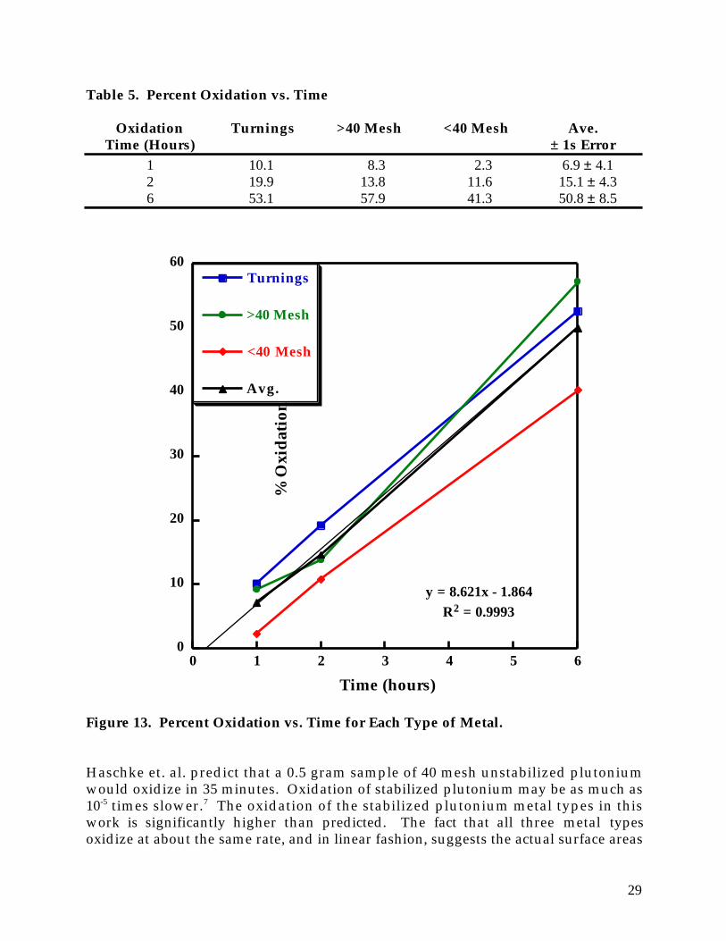
where: (% Metal)initial = pre-oxidation % Pu metal (% Metal)final = post-oxidation % Pu metal Table 5 summarizes percent oxidation vs. time for the three metal types. Except forthe 6 hour value for the >40 mesh sample there appears to be a trend in the extent ofoxidation with particle size that is the inverse of what would be expected; thepercent oxidation decreases with particle size! Perhaps the expected surface areaeffect is being negated by surface oxides that coat all the metal types. This data hasimplications for the plutonium metal in the Rocky Flats combustible residues. Evenif those materials contain plutonium much finer than 40 mesh, they may not be anymore reactive than the plutonium used in these experiments. Figure 13 plots thepercent oxidation vs. time for each type of metal. The average oxidation percentagefor the three plutonium metal types increases linearly over 6 hours. Although theplutonium is becoming more finely divided with longer oxidation times, the linearpercent oxidation curve suggests that the dispersal of the metal has no effect on theextent of oxidation. If fifty percent oxidation occurred in 6 hours, then anextrapolation of data suggests that complete oxidation might occur in 12 hours.
29
Table 5. Percent Oxidation vs. Time
Oxidation Turnings >40 Mesh <40 Mesh Ave. Time (Hours) ± 1s Error
1 10.1 8.3 2.3 6.9 ± 4.1 2 19.9 13.8 11.6 15.1 ± 4.3 6 53.1 57.9 41.3 50.8 ± 8.5
0
10
20
30
40
50
60
0 1 2 3 4 5 6
Turnings
>40 Mesh
<40 Mesh
Avg.
Time (hours)
% O
xid
atio
n
y = 8.621x - 1.864
R2 = 0.9993
Figure 13. Percent Oxidation vs. Time for Each Type of Metal. Haschke et. al. predict that a 0.5 gram sample of 40 mesh unstabilized plutoniumwould oxidize in 35 minutes. Oxidation of stabilized plutonium may be as much as10-5 times slower.7 The oxidation of the stabilized plutonium metal types in thiswork is significantly higher than predicted. The fact that all three metal typesoxidize at about the same rate, and in linear fashion, suggests the actual surface areas

30
of these metals may be much higher than the calculations based on the metalparticle sizes. Perhaps microscopic cracks formed in the metals during machiningand the surface areas in these cracks really accounts for a much larger surface area.This may account for the higher oxidation rate. If all the metal types have about thesame surface area resulting from these types of cracks, then the nearly uniformoxidation rate can be understood. Our earlier oxidation experiments have shown that additives such as sulfamic acid,H2O2 or CCl4 can enhance the oxidation.5,6 The addition of additives is notconsidered an option for this process. However, residual CCl4 from the desorptionprocess may react with water to produce HCl, resulting in an enhanced oxidation.However, HCl causes reactor corrosion and could drop the pH of the product out ofWIPP-WAC compliance. We submitted five of our small scale (~0.5 grams plutonium) samples for DTAanalysis. The samples were surrogate only, surrogate/plutonium with no oxidation,surrogate/plutonium turnings with a two hour oxidation, surrogate/>40 meshplutonium with a two hour oxidation, and surrogate/<40 mesh plutonium with a
-55
-50
-45
-40
-35
-30
-25
-20
-15
-10
-5
0
5
20 30 40 50 60 70 80 90 100 110 120 130 140 150 160 170 180 190
Temperature (°C)
Del
ta T
(°C
)
Figure 14. Differential Thermal Analysis Plot for Oxidized Plutonium Turningsand Surrogate.

31
two hour oxidation. The surrogate/oxidized plutonium turnings plot is shown inFigure 14. Beginning at 25˚C and ending between 100˚C and 110˚C there is a slowsweeping endotherm. This was typical of the five analyses. Thus all the oxidizedsamples passed the Rocky Flats stabilization criterion of not having an exothermbelow 60˚ C. All sample baselines exhibit a slight endotherm of less than anabsolute magnitude of 5˚C, that started between 120˚C and 130˚C and ended justbefore 140˚C. This was likely due to a common substance in the samples that wentthrough a phase change, such as a melt. This is consistent with the earlierobservation that the surrogate starts to melt and become sticky at about thesetemperatures.

32
SUMMARY AND CONCLUSIONS The major conclusions that the LANL work has reached for the RFETS proposedprocess to stabilize combustible residues are listed below. Carbon Tetrachloride Desorption • Wet surrogate has poor heat and mass transfer properties. Surrogate
composition and cut may affect these properties.• Desorption of CCl4 from wet surrogate using either the induction or no
induction method gave highly variable results. The induction method may be aslightly more consistent method.
• An average of 634 ± 160 ppm CCl4 remained in the headspace of the reactor aftera 200 minute induction desorption procedure; >98% of the CCl4 was removedfrom the wet surrogate; this meets the WIPP-WAC regulations.
• The large standard deviations for the desorption methods are caused byvariability in the packing of surrogate, composition and cut of the surrogate,placement of CCl4 in the surrogate, and placement of thermocouple in thesurrogate.
• If no process monitoring is used to measure the CCl4 concentration coming offthe reactor, then a set time of ~240 minutes should be allotted for the desorptionstep to insure that sufficient removal of CCl4 has occurred.
• Condensing the desorbed CCl4 from high velocity gas streams was inefficient.• Air or nitrogen can be used for the for CCl4 desorption; safety concerns would
warrant the use of N2.• Residual CCl4 left after desorption may react with water during the steam
oxidation step to produce HCl; this may lead to unwanted corrosion problems.• Dispersal of the shredded material may be a more efficient desorption method
than the reactor desorption methods; CCl4 evaporation rates in an open systemcan be as high as 8 g/min.
Water Additions • Wet surrogate sorbs an equal weight of water; 500 grams of surrogate sorbs 500
grams of water.• The weight of 90°C water added to wet surrogate affects the maximum surrogate
temperature within a closed 110°C reactor; maximum temperatures are reachedwithin 100 minutes.
• Free water in the closed hot reactor is required to efficiently transfer heat fromthe reactor to the wet surrogate.
• In general, >500 grams of 90°C water are needed to rapidly bring 500 grams of wetsurrogate to the optimum plutonium oxidation temperature range, 100°C -120°C.

33
• Within 300 minutes, addition of <400 grams of 90°C water to 500 grams of wetsurrogate failed to reach 100°C.
• Variability in the observed maximum surrogate temperatures are due todifferences in the heating behavior of the Parr® reactor from one experiment tothe next and the effect that different placements of the thermocouple within thesurrogate has on the observed temperature and, for cascade controllers, how thatsurrogate temperature effects the reactor heating.
• If more than 333 mL of water are required to oxidize the plutonium in a RockyFlats combustible sample, then a drying step will be needed to insure that the sixsamples per WIPP barrel do not exceed the limit of two liters of free water.
• Desorption of excess water from water saturated wet surrogate with 75 L/min110°C air averaged 3 g/min. Desorption of excess water has operational andsafety benefits.
• Some oil distills during the CCl4 desorption and water evaporation steps. Plutonium Oxidation • Submersing the plutonium used in this study in water inhibits the oxidation.
This observation may conflict with the water addition requirements for theoxidation.
• The residual water in the oxidized sample had a pH between 6.0 and 6.5. Theoxidized samples generated little or no gas when submerged in water for 1 hour.DTA analyses of the oxidized samples exhibited no exotherms below 60°C. Thesesamples meet the DOT and WIPP-WAC criteria.
• The three sizes of plutonium metal oxidized at approximately the same rate.Based on the calculated surface areas, the < 40 mesh metal should have reacted 2-5 times faster than the >40 mesh metal and metal turnings.
• The plutonium used in these studies oxidized significantly faster than expectedfor stabilized plutonium but slower than pure plutonium metal.
• The average oxidation rate for the plutonium metals used in this work wasnearly linear over 6 hours.
• Fifty percent oxidation occurred in 6 hours; complete oxidation might occur in 12hours.
• Residual CCl4 from incomplete desorption could enhanced the water oxidationthrough the production of HCl. However, HCl causes reactor corrosion andcould drop the pH of the product out of WIPP-WAC compliance.
The original RFETS processed allotted two hours to perform the desorption andoxidation steps. In summary, the LANL work has shown that these steps will takesignificantly longer than this. Assuming that: 1) no process monitoring is used forthe CCl4 desorption, 2) 500 mL of water are used for the oxidation, 3) 6 hours arerequired for the steam oxidation to produce samples that meet the stabilizationcriteria, 4) water desorption occurs at 3 g/min, and 5) the reactor needs 60 minutes tocool to 50°C, then 12 hours will be needed to process one 500 gram batch ofcombustible residues.

34
Application of LANL Results to RFETS
The purpose of this section is to recommend the Parr® reactor configuration thatshould be used by RFETS personnel for the stabilization of organic contaminatedcombustible residues based on the information gathered during experimentation.This recommendation maintains that the desorption process continues to be donewithin the reactor because not enough data has been obtained for desorbing CCl4
from dispersed shredded material to justify altering the original process description.Table 6 summarizes the suggested operating parameters.
Table 6. RFETS Operating Parameters for Stabilizing Combustible Residues
Process Parameter Value
Batch Preparation Combustible Residue 500 gBatch Size
Desorption Air or N2 Flow Rate 75 L/minAir or N2 Temperature 110°C
Desorption Completion Internal Thermocouple 90°CTemperature
Plutonium Oxidation Water Feed Batch Size 500 mLWater Preheat Temperature 100°CInternal Oxidation Temperature 100°C - 120°COxidation Processing Time 6 hoursCool Reactor Temperature 50°C
System Configuration: Details of the system configuration are illustrated in Figures1 and 2. The Design of the system varies slightly compared to the original RFETSdesign. Design modifications are as follows:
• The water injection tube should allow the liquid to contact the side of the reactorwhen injected. This will flash the water to vapor.
• The process logic controller (PLC) system must be outside of the glove boxenvironment. Frequent failure of the PLC was attributed to corrosion fromprocess steam. In addition, CCl4 vapor will react with water to give HCl whichwill lead to further corrosion.
• The basket should not be constructed with the stainless steel mesh as originallydesigned as corrosion of the welded edges caused the mesh to fray; frayed metal isa potential safety hazard since it may cause glove failure. The basket should beconstructed of a stainless steel rod frame that forms a frame for the nylon hopsack.

35
Batch Size and Batch Preparation: The batch size should be limited to 500 grams ofsurrogate as additional material would need to be compacted in order to fit into thereactor basket. Compacting the material would decrease the mass and heat transferrates during desorption and oxidation. The use of the nylon hop sack is advised asthe sack increases the ease of material handling and decreases combustible materialspread outside the reactor basket. Oxidation water should be prepared by adding 500mL to the water supply vessel and beginning the preheat process. The water shouldbe preheated to 100°C prior to reactor injection during oxidation.
Desorption of Volatile Organic Material: After the reactor is sealed and all inletand outlet valves closed, it should be inductively preheated for one hour. The airinlet and off-gas outlet should next be opened and the system sparged with 110°C airat 75 L/minute until the internal thermocouple (the thermocouple in center of thecombustible material) reaches 90°C.
Plutonium Oxidation: The oxidation should begin by pulling a vacuum on thereactor then closing all valves. Next, the drain should be opened to the (preheated)water supply and the water transferred into the reactor vessel. When the internalthermocouple (thermocouple in center of combustible material) reaches 100°C, thistemperature (between 100°C and 120°C) should be held for 6 hours. Finally, thereactor should be allowed to cool to approximately 50°C and the vessel should bevented before breaking the collar seal.

36
ACKNOWLEDGMENTS
The authors wish to thank Kent D. Abney for his consultation and guidance on theuse of the glovebox and facilities he manages in the Alpha Facility at TA-48, LosAlamos National Laboratory. We also thank David V. Martinez, Los Alamos, forthe CCl4 headspace analyses, Jay S. Samuels and Kevin J. Kuhn, Los Alamos, for theDTA analyses, and Dr. Kenneth Ashley, a visiting scientist from Texas A&M-Commerce, who offered many helpful suggestions during the course of this projectand never hesitated to offer assistance when asked.

37
REFERENCES
1. Criteria for Interim Safe Storage of Plutonium-Bearing Solid Materials, Addendum to The Department of Energy Implementation Plan for DNFSB Recommendation 94-1, Department of Energy, November 1995.
2. Waste Isolation Pilot Plant Waste Acceptance Criteria, DOE/WIPP-069, Revision 5, Change Notice #2, February 1998.
3. Code of Federal Regulations, 40 CFR 261.22 and 49 CFR 173.187.
4. RFETS Activity Control Envelope (ACE) for Building 371 Wet Combustible Stabilization, 371-ACE-COMB-001, Rev. 1, December 17, 1996.
5. Schroeder, N. C. and Attrep, M., Jr., "Rocky Flats Wet Combustibles Residue Treatment, Report 1: Wet Combustible-Cerium Studies," Los Alamos National Laboratory Report, LA-UR-962337, Los Alamos, NM (1996).
6. Williams, S. B., Schroeder, N. C. and Attrep, M., Jr., "Rocky Flats Wet Combustible Residue Treatment, Cerium Metal Oxidation Studies and Status Report," Los Alamos National Laboratory internal report, Los Alamos, NM (1996).
7. Haschke, J. M., Allen, T. H., and Stakebake, J. L., “Reaction Kinetics of Plutonium with Oxygen, Water, and Air: Moisture Enhancement of the Corrosion Rate,” Los Alamos National Laboratory Report, LA-UR-96-632, Los Alamos, NM (1996).
8. Liebman, C., “Transuranic Waste Characterization Program Plan”, DTP-1.2-042, Los Alamos National Laboratory, Los Alamos, NM (1998).
9. Jenkins, W. J., J. Inorg. Nucl. Chem , 25 , 463 (1963).