author's personal copy - university of massachusetts...
TRANSCRIPT

This article was published in an Elsevier journal. The attached copyis furnished to the author for non-commercial research and
education use, including for instruction at the author’s institution,sharing with colleagues and providing to institution administration.
Other uses, including reproduction and distribution, or selling orlicensing copies, or posting to personal, institutional or third party
websites are prohibited.
In most cases authors are permitted to post their version of thearticle (e.g. in Word or Tex form) to their personal website orinstitutional repository. Authors requiring further information
regarding Elsevier’s archiving and manuscript policies areencouraged to visit:
http://www.elsevier.com/copyright

Author's personal copy
Available online at www.sciencedirect.com
Journal of Power Sources 179 (2008) 310–316
Mechanism for electrochemical hydrogen insertion incarbonaceous materials
Deyang Qu ∗Department of Chemistry, University of Massachusetts Boston, Boston, MA 02482, United States
Received 27 December 2007; accepted 31 December 2007Available online 5 January 2008
Abstract
The mechanism for safe and reversible storage of hydrogen in porous carbonaceous materials by electrochemical decomposition of water inalkaline electrolyte is proposed. Atomic H was found to be inserted into the microdomains of defective graphene layers. Hydrogen storage capacityincreases with increasing interlayer distance between carbon sheets. Hydrogen insertion in carbonaceous materials occurs at ambient conditions.Static potential acts as an electrochemical valve which can retain the hydrogen in the carbon structure, thus preventing leakage during storage.© 2008 Elsevier B.V. All rights reserved.
Keywords: Energy conversion; Intercalations; Hydrogen storage; Porous carbon; Electrochemistry
1. Introduction
The replacement of fossil fuels with hydrogen, which can beproduced from renewable sources and burn pollution free, coulddramatically reduce the buildup of greenhouse gases which maycause severe climate change. Finding a safe, cheap and simplemethod to store hydrogen, together with producing hydrogenand converting it to electricity are two of the most daunting chal-lenges facing scientists at the present time. Unfortunately, noneof the existing H2 storage methods – including hydrogen com-pression and liquefaction under cryogenic conditions, chemicaland metal hydrides and gas-on-solid adsorption – satisfy all thecriteria.
One way to increase volumetric hydrogen density to thelevel of liquid hydrogen under ambient conditions is the dis-sociation of hydrogen molecules in combination with a tightbinding or electron transfer to the host material. The storage ofelectrochemically generated hydrogen has found a wide appli-cation in multi-component metal-hydride alloys. Many metalsand alloys are able to reversibly store large amounts of hydro-gen, and this system has been studied extensively over thepast four decades [1–4]. Hydrogen filling can be done using
∗ Tel.: +1 617 287 6035; fax: +1 617 287 6185.E-mail address: [email protected].
molecular hydrogen gas, which is dissociated at the surface tobecome adsorbed H atoms, or adsorbed hydrogen atoms electro-chemically generated from aqueous electrolytes. The adsorbedH atoms then diffuse into the matrix of the hydride mate-rial and reside in tetrahedral or octahedral interstitial sites.Upon release, the atomic hydrogen stored in the interstitialsites recombines at particle surface sites to form molecularhydrogen. However, most effective metal hydrides are madeof relatively heavy elements such as Ni, Co and La, and thegravimetric capacity of regular hydrides is less than 2 wt.% [5],which is significantly lower than the Department of Energy(DOE)’s goal of 6.5 wt.%. Alloys with lighter elements, e.g.Mg [6,7], have also been investigated for a higher gravimetricstorage capacity (3–7 wt.%), but for thermodynamic reasons,they only release hydrogen at a high temperature (>500 ◦C).The kinetic aspect of hydrogen release can be improved bynanostructuring and adding a catalyst, whereby the thermody-namics remain unchanged. Recently a new group of low tomedium temperature chemical hydrides, nitrides and imides,including MAlH4, MBH4, Li3N, etc., have attracted significantattention [8–12]. A large amount of hydrogen can be stored inthese materials and with a catalyst, hydrogen can be releasedeasily at almost ambient conditions. Despite these advantages,two major obstacles remain: firstly, the generation of hydrogenis irreversible and lengthy, and solvent-based synthetic pro-cesses may be involved to re-generate the compounds; secondly,
0378-7753/$ – see front matter © 2008 Elsevier B.V. All rights reserved.doi:10.1016/j.jpowsour.2007.12.098
Author's personal copy
D. Qu / Journal of Power Sources 179 (2008) 310–316 311
significant volume change (15–25%) needs to be accommo-dated.
Metal-hydride alloys, which have been used for electrochem-ical hydrogen storage, are heavy, expensive and not stable. Dueto the good electronic conductivity and light weight of carbon,hydrogen sorption during electro-decomposition of water on acathodically polarized carbon electrode is an alternative and ele-gant method for hydrogen storage at an ambient temperature andpressure [13,14]. For hydrogen storage alloys, hydrogen atomsenter the metal lattice for the hydride (reduced) state [15]. Eventhough electrochemically formed hydrogen can be stored incarbon material [16], the mechanism is still under debate. Elec-trochemical methods have also been used as an alternative andeffective method for storing hydrogen in carbonaceous materi-als at an ambient temperature and pressure [17]. In most of thestudies, the electrodes contained nanotubes [18–21]. Due to poorconductivity, nanotubes are always a minor fraction mixing withother metallic conductive fillers, e.g. Ni (>90%) [19], Cu in theratio of 1:3 [21], thus, the gravimetric capacity of nanotubes issignificantly limited. Indeed, the practical value of nanotubularmaterials is dubious due to the cost, limited scale of produc-tion, and uncertain purity. Activated carbon and carbon fibershave been demonstrated as good candidates for electrochemicalhydrogen storage [13,17,22,23]. However, the results reportedin the literature are very inconclusive; for example, the double-layer contribution, which is significant for electrodes made withhigh surface area carbon material [24,25], was not corrected inmany reports. Thus the calculated hydrogen storage based ondischarge capacity is inflated. The proposed mechanisms forhydrogen storage, e.g. the adsorption of electrochemically gen-erated molecular hydrogen in micro-pores [16] and the so-called“nascent-hydrogen” adsorbed on the surface of carbon [13], lacksufficient experimental support. The intercalation of hydrogeninto the interlayer of carbon is believed to be prohibited [26],which was a highly questionable conclusion.
2. Experimental details
Ultra high surface area carbon materials were either obtainedfrom carbon manufacturers or made in-house by modifying dif-ferent precursor materials through various activation proceduresin order to create various porosities and structures. Table 1 tabu-lates the surface area, average pore size, type and manufacture ofthe activated carbon materials used in the studies. All activatedcarbon materials were reflux-washed with acetone in a Soxhletextractor for 48 h to remove most of the weakly bonded surfacefunctional groups that remained from the precursors and themanufacturing process. All U-grade carbon materials were acti-vated at 800–900 ◦C in steam mixing with various percentagesof CO2.
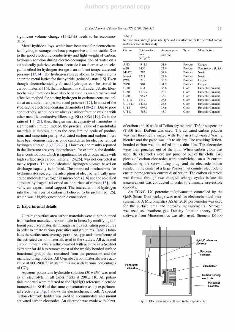
Aqueous potassium hydroxide solution (30 wt.%) was usedas an electrolyte in all experiments at 298 ± 1 K. All poten-tials reported were referred to the Hg/HgO reference electrodeimmersed in KOH of the same concentration as the experimen-tal electrolyte. Fig. 1 shows the electrochemical cell. A specialTeflon electrode holder was used to accommodate and mountactivated carbon electrodes. An electrode was made with 90 wt.
Table 1Surface area, average pore size, type and manufacture for the activated carbonmaterials used in this study
Carbon Total surfacearea(m2 g−1)
Average pore
size ( ´̊A)
Type Manufacture
APD 941.1 31.6 Powder Calgonm20 1450 22.9 Powder Spectrocorp (USA)M1470 783 54.6 Powder NoritNor-A 1211 24.6 Powder NoritPWA 718 36.9 Powder CalgonWPH 904 31.9 Powder CalgonU-1B 631 35.6 Cloth Emtech (Canada)U-2B 1179.4 28.1 Cloth Emtech (Canada)U-6B 957.5 36.1 Cloth Emtech (Canada)U-11B 1349 28.8 Cloth Emtech (Canada)U-L1-I3 1437.1 28.5 Cloth Emtech (Canada)U-T2 996.1 38.6 Cloth Emtech (Canada)U-T13 755.7 45.7 Cloth Emtech (Canada)
of carbon and 10 wt.% of Teflon dry material. Teflon suspension(T-30) from DuPont was used. The activated carbon powderwas first thoroughly mixed with T-30 in a high-speed Waringblender and the paste was left to air dry. The resulting Teflon-bonded carbon was hot-rolled into a thin film. The electrodeswere then punched out of the film. When carbon cloth wasused, the electrodes were just punched out of the cloth. Twopieces of carbon electrodes were sandwiched on a Pt currentcollector by the screw-fitting plug, and the electrode holderresided in the center of a large Pt-mesh net counter electrode toensure homogeneous current distribution. The carbon electrodewas formed through two charge/discharge cycles before themeasurement was conducted in order to eliminate irreversiblecapacity.
An EG&G 170 potentiostat/galvanostat controlled by theQ&R Smart Data package was used for electrochemical mea-surements. A Micromeritics ASAP 2020 porosimeter was usedfor the surface area and porosity measurements. Nitrogenwas used as absorbent gas. Density function theory (DFT)software from Micromeritics was also used. Siemens D5000
Fig. 1. Electrochemical cell used in the experiments.

Author's personal copy
312 D. Qu / Journal of Power Sources 179 (2008) 310–316
Fig. 2. Discharge of stored hydrogen, double-layer contribution.
powder diffractometer (XRD) equipped Cu target X-ray tubeand monochrometer was used for all X-ray diffraction measure-ments.
3. Results and discussion
3.1. Impact of double-layer capacitance
When dc voltage is applied to the interface of an electrode,an electric double-layer is then established to store electricalenergy. The electrical capacitance stored in the layer is propor-tional to the surface area of the electrode and 1/thickness of thedouble-layer. In a strong and concentrated electrolyte solution,a double-layer has a thickness of only a few angstroms. Theelectrodes used in the electrochemical hydrogen storage studieswere made of high surface area carbon materials, so the con-tribution of the double-layer has to be considered in order notto inflate the electrochemical hydrogen storage capacity. Fig. 2shows the impact of the double-layer. The electrode was firstcharged to −800 mV versus Hg/HgO, which is below hydrogenunder potential deposition (UPD) potential. The charges wereall used to charge the double-layer. The electrode was then dis-charged to release the charges stored in the double-layer, thenthe contribution of the double-layer for the electrode capacitycould be calculated, as shown in Fig. 2. The double-layer con-tribution was subtracted for all the hydrogen capacity reportedin this paper.
3.2. X-ray diffraction patterns and d0 0 2 calculation
Fig. 3 shows the typical XRD patterns for the high surfacearea carbon materials used in these studies. The clear observa-tion of (1 0 0) peak near 42◦ and (1 1 0) peak near 79◦ indicatesthat the activated carbons consist of small domains or orderedgraphene sheets. The interlayer distance between the graphenesheets (d0 0 2) was calculated from the scattering angle of (0 0 2)peak using the Bragg equation. The fittings of (0 0 2) peak arealso shown in Fig. 3. The scattering angles for both (1 0 0) and
Fig. 3. XRD for WPH and U-Ti3 activated carbon. The enlargement of (0 0 2)peaks and fittings are shown in the inset.
(1 1 0) peaks remain the same for the two carbon materials, whichconfirms that the difference of the scattering angle of (0 0 2) peakdid not result from sample displacement error. In a high surfacearea carbon material, a graphene sheet may only consist of afew carbon hexagons with dislocation, which may not be a pla-nar sheet, as is the case with those in a graphite. The defectivegraphene sheets may stack together and form small domains withshort-range order as shown in Fig. 6. When the organized regionscontain a significant number of graphene sheets with no parallelneighbor, then strong background scattering develops at (0 0 2)peak position [27]. Owing to the strong scattering background,it is very difficult to accurately determine the d0 0 2 value for anactivated carbon using the Bragg equation. However, it appearsthat the estimated d0 0 2 values could roughly represent the short-range structure of activated carbon. XRD patterns of all carbonsamples are included in on-line supplementary information.
3.3. Electrochemical hydrogen adsorption
Fig. 4 shows the comparison of electrochemical oxidation ofhydrogen stored in an activated carbon electrode after restingat different conditions. After the same amount of hydrogen wasloaded through decomposition of alkaline electrolyte, the storedhydrogen was released through electrochemical oxidation after10 s of rest, 48 h of rest at open circuit voltage (OCV) and 48 hrest at the constant potential of −1.250 V versus HgO/Hg. Asshown in Fig. 4, half of the initially stored reversible hydrogenremained even after 48 h of rest at OCV.
Various carbon materials have unique pore distribution. Thetotal surface of a fine powder comprises the walls of all pores.The information regarding the surface area and the porosity ofthe carbons was obtained through nitrogen adsorption isothermusing DFT. However, it is difficult to explain how electrochem-ically generated molecular H2 could form a stable monolayerin ambient conditions in the porous structure of an activatedcarbon, as claimed in the literature [28], given the intrinsic dif-ficulty for the carbon surface-H2 van der Walls interaction to

Author's personal copy
D. Qu / Journal of Power Sources 179 (2008) 310–316 313
Fig. 4. Comparison of the oxidation of hydrogen electrochemically stored inM20 activated carbon electrode after resting at various conditions. Hydrogenwas pre-loaded into the electrode by the reduction of 30 wt.% KOH electrolyteat 20 mA for 8 h. The weight of the electrode was 0.191 g. −1.25 V vs. Hg/HgOwas 70 mV more positive than the hydrogen generation potential for the carbonelectrode (−1.32 V).
compete with thermal energies. The process of hydrogen inter-calation must always be distinguished from both physical andchemical surface adsorption. One of the characteristics of sur-face adsorption is that its capacity normally relates to the surfacearea of the material: the higher the surface area, the larger theamount of adsorption. Fig. 5 shows the relationship betweenthe total surface area of the carbon materials and the amount ofhydrogen reversibly adsorbed in them. No clear correspondencecan be observed between the surface area and hydrogen elec-trochemical adsorption, which suggests that the majority of thehydrogen may not resist on the surface of carbon material. It is
Fig. 5. Relationship between surface area and reversibly adsorbed hydrogencapacity.
worth emphasizing that some electro-adsorbed hydrogen atomswould remain on the carbon surface and would reach a dynamicequilibrium with those inserted in the interlayer space.
It has been reported that H atoms from the dissociation ofmolecular hydrogen could intercalate into the graphite interlayerstructure [29]. Fig. 6 illustrates the structure of the activated car-bons and the possible mechanism for H insertion. The structureof defective graphene layer domains in the high surface areacarbon provides the micro-units for the hydrogen accommo-dation. High surface area amorphous carbons consist of smallhexagonal carbon rings, which are called “graphene layers”.Unlike the well ordered and planar graphene sheets in graphi-tized carbon, the sheets in the activated carbons are highlydefective and may be curved. The carbons are made up of
Fig. 6. Illustration of H electrochemical insertion into interlayer structure of microdomain of graphene layers.

Author's personal copy
314 D. Qu / Journal of Power Sources 179 (2008) 310–316
associations, roughly parallel in structure and quite defectivenon-planar graphene sheets, like a “house of cards” [30]. Carbonmaterials made from different precursors and via different prepa-ration methods have different size orientation and the stackingof their defective micro-graphene sheets is different. But in gen-eral, an activated carbon has an amorphous structure and lackslong-range three-dimensional order. An activated carbon can beconsidered as molecular space, this space being contained withina three-dimensional network of carbon atoms arranged in layerscomposed of range structures joined together somewhat imper-fectly. This network is continuous in three dimensions, withsome layers being stacked, roughly parallel to each other, ingroups of two, or three, probably not much more [31]. Thus, thehigh surface area carbon materials are made up of randomly ori-ented single defective graphene sheets that contain appreciablenanoporosity with pores of the order of the size of graphenesheets and are stacked rather like a house of cards [32,33].The majority of the electrochemically generated atomic hydro-gen is proposed to reside in the interlayer space of defectivegraphene layers and the nanopores created by defective singlecarbon sheets of activated carbon. The minority of this hydro-gen is chemically adsorbed onto the surface of either edge orbasal orientations. The hydrogen on the edge orientation of thegraphene layer domain is capable of diffusing into the interlayerspace, while that adsorbed on the basal layer would remain onthe surface. Due to the defective nature of the graphene sheetsin amorphous carbon, the stable adsorption of atomic hydrogenon the basal layer would be at the sites of defect.
In the electrochemical reduction process, hydrogen atomsare formed at the surface of the electrode when the elec-trons transfer from the carbon electrode to H2O moleculesand are electrosorbed on the surface of the carbon electrode(Volmer reaction). C(e) + H2O�CHads + OH−. There could betwo competitive paths for the adsorbed H:
• Via desorptive recombination (Tafle reaction),2CHads �H2 + C or “atom-ion” electrodesorption of H(Heyrovsky reaction), CHads + C(e) + H2O�H2 + OH−[34].
• Followed by H intercalation/insertion into the lattice of hostmaterial, e.g. metal alloy or interlayer of carbon.
In the electrochemical oxidation process, H residing in theinterlayer diffuses to the surface of the carbon electrode, givesone electron to the carbon host electrode, combines with an OH−ion and forms H2O. CHads + OH− → C(e) + H2O. The H inter-calation reaction would be the dominant reaction at low surfacecoverage of electrosorbed H, since the rate of H2 evolution is pro-portional to the degree of H monolayer coverage on the electrodesurface. The intercalation process goes on until the majority ofthe surface is covered with a monolayer of electrosorbed H, whena significant amount of H2 starts to be generated. Fig. 7 shows therelationship between galvanostic discharge/charge efficiency,the hydrogen adsorption capacity (mAh g−1) with the chargingcapacity. It is clearly demonstrated that the discharge/charge effi-ciency decreases with increasing charging capacity, even thoughthe net discharge capacity increases with the charging capacity.
Fig. 7. Discharge and charge efficiency for hydrogen insertion. The electrodewas made with M1470 activated carbon. The electrode was charged (reduction)at 100 mA g−1 current density and discharged (oxidation) at 50 mA g−1 currentdensity. The efficient was defined as the percentage of oxidation capacity againstreduction capacity.
The phenomena could be explained by the fact that before elec-trosorbed H coverage reaches the critical point, the majority ofthe H atoms on the edge surface become intercalated into the car-bon interlayer and remain chemically adsorbed on the surfaceof the carbon, so they can be oxidized in the discharge process.As the charging continues, more and more H atoms recombinewith their neighbors, forming H2, which will not contribute tothe discharge capacity. When the surface of the electrode is100% covered by electrosorbed H, the discharge capacity onlyincreases slightly, due to the continuous H insertion into theinterlayer. The self-discharge phenomenon illustrated in Fig. 4can also be explained by the proposed mechanism. During therest at OCV, the intercalated H can gradually diffuse to the sur-face of the electrode and become surface adsorbed H; two ofthe neighboring H atoms could then recombine to form molec-ular hydrogen, which subsequently escapes from the electrodesurface. Apparently, the H self-diffusion and recombination pro-cesses are kinetically slow; almost half of the original insertedH was preserved after 48 h of storage. It is interesting to notethat after the carbon electrode was held at the constant potential,which was slightly more positive than the hydrogen generationpotential for 48 h, the total hydrogen capacity did not changebut the profile of the electrochemical oxidation curve changed.Since the resting potential was more positive than the waterelectrolysis potential, there was no additional atomic H beingproduced. Unlike the self-discharge (leakage of hydrogen) ofthe hydrogen loaded electrode resting at OCV, almost all theexisting H was preserved in the carbon structure due to the factthat the adsorbed H atoms are strongly electrosorbed by theapplied potential. It seems that instead of diffusion and recom-bination to form molecular hydrogen, the surface adsorbed Hatoms and intercalated H atoms in the interlayer were allowedto redistribute to reside at more energy favorable locations in thecarbon structure during the rest at static potential. This demon-strated through the profile change for the hydrogen oxidation
Author's personal copy
D. Qu / Journal of Power Sources 179 (2008) 310–316 315
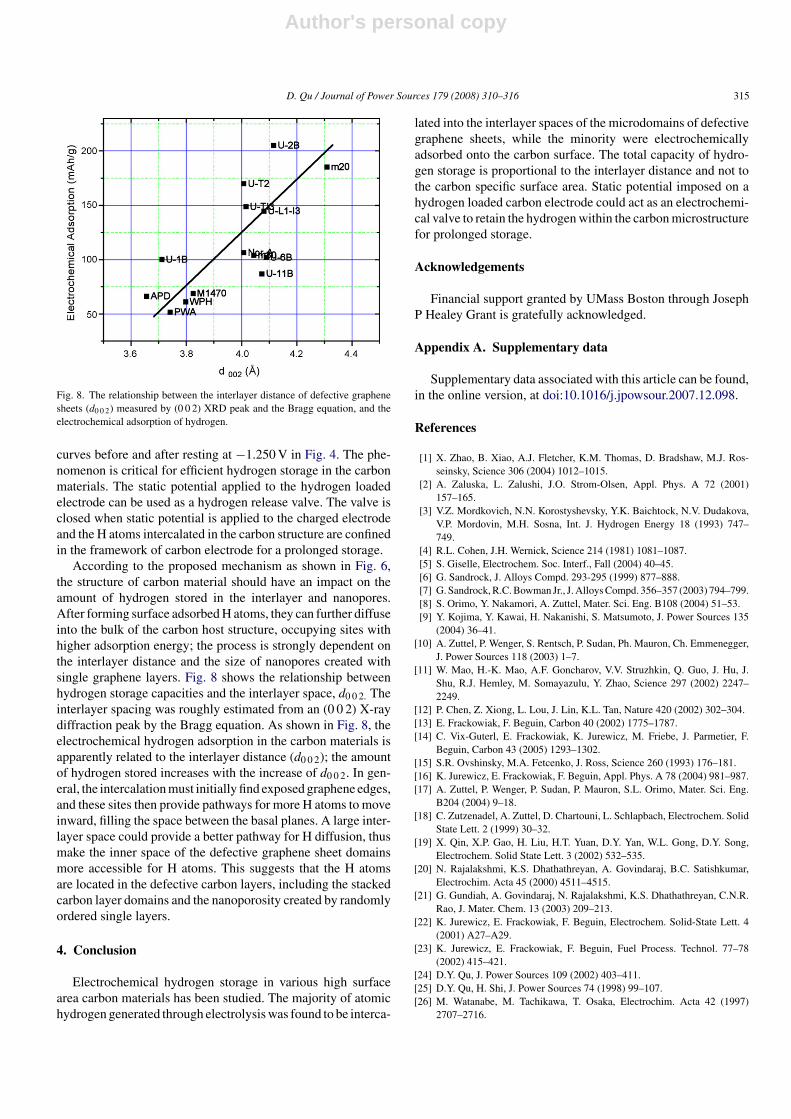
Fig. 8. The relationship between the interlayer distance of defective graphenesheets (d0 0 2) measured by (0 0 2) XRD peak and the Bragg equation, and theelectrochemical adsorption of hydrogen.
curves before and after resting at −1.250 V in Fig. 4. The phe-nomenon is critical for efficient hydrogen storage in the carbonmaterials. The static potential applied to the hydrogen loadedelectrode can be used as a hydrogen release valve. The valve isclosed when static potential is applied to the charged electrodeand the H atoms intercalated in the carbon structure are confinedin the framework of carbon electrode for a prolonged storage.
According to the proposed mechanism as shown in Fig. 6,the structure of carbon material should have an impact on theamount of hydrogen stored in the interlayer and nanopores.After forming surface adsorbed H atoms, they can further diffuseinto the bulk of the carbon host structure, occupying sites withhigher adsorption energy; the process is strongly dependent onthe interlayer distance and the size of nanopores created withsingle graphene layers. Fig. 8 shows the relationship betweenhydrogen storage capacities and the interlayer space, d0 0 2. Theinterlayer spacing was roughly estimated from an (0 0 2) X-raydiffraction peak by the Bragg equation. As shown in Fig. 8, theelectrochemical hydrogen adsorption in the carbon materials isapparently related to the interlayer distance (d0 0 2); the amountof hydrogen stored increases with the increase of d0 0 2. In gen-eral, the intercalation must initially find exposed graphene edges,and these sites then provide pathways for more H atoms to moveinward, filling the space between the basal planes. A large inter-layer space could provide a better pathway for H diffusion, thusmake the inner space of the defective graphene sheet domainsmore accessible for H atoms. This suggests that the H atomsare located in the defective carbon layers, including the stackedcarbon layer domains and the nanoporosity created by randomlyordered single layers.
4. Conclusion
Electrochemical hydrogen storage in various high surfacearea carbon materials has been studied. The majority of atomichydrogen generated through electrolysis was found to be interca-
lated into the interlayer spaces of the microdomains of defectivegraphene sheets, while the minority were electrochemicallyadsorbed onto the carbon surface. The total capacity of hydro-gen storage is proportional to the interlayer distance and not tothe carbon specific surface area. Static potential imposed on ahydrogen loaded carbon electrode could act as an electrochemi-cal valve to retain the hydrogen within the carbon microstructurefor prolonged storage.
Acknowledgements
Financial support granted by UMass Boston through JosephP Healey Grant is gratefully acknowledged.
Appendix A. Supplementary data
Supplementary data associated with this article can be found,in the online version, at doi:10.1016/j.jpowsour.2007.12.098.
References
[1] X. Zhao, B. Xiao, A.J. Fletcher, K.M. Thomas, D. Bradshaw, M.J. Ros-seinsky, Science 306 (2004) 1012–1015.
[2] A. Zaluska, L. Zalushi, J.O. Strom-Olsen, Appl. Phys. A 72 (2001)157–165.
[3] V.Z. Mordkovich, N.N. Korostyshevsky, Y.K. Baichtock, N.V. Dudakova,V.P. Mordovin, M.H. Sosna, Int. J. Hydrogen Energy 18 (1993) 747–749.
[4] R.L. Cohen, J.H. Wernick, Science 214 (1981) 1081–1087.[5] S. Giselle, Electrochem. Soc. Interf., Fall (2004) 40–45.[6] G. Sandrock, J. Alloys Compd. 293-295 (1999) 877–888.[7] G. Sandrock, R.C. Bowman Jr., J. Alloys Compd. 356–357 (2003) 794–799.[8] S. Orimo, Y. Nakamori, A. Zuttel, Mater. Sci. Eng. B108 (2004) 51–53.[9] Y. Kojima, Y. Kawai, H. Nakanishi, S. Matsumoto, J. Power Sources 135
(2004) 36–41.[10] A. Zuttel, P. Wenger, S. Rentsch, P. Sudan, Ph. Mauron, Ch. Emmenegger,
J. Power Sources 118 (2003) 1–7.[11] W. Mao, H.-K. Mao, A.F. Goncharov, V.V. Struzhkin, Q. Guo, J. Hu, J.
Shu, R.J. Hemley, M. Somayazulu, Y. Zhao, Science 297 (2002) 2247–2249.
[12] P. Chen, Z. Xiong, L. Lou, J. Lin, K.L. Tan, Nature 420 (2002) 302–304.[13] E. Frackowiak, F. Beguin, Carbon 40 (2002) 1775–1787.[14] C. Vix-Guterl, E. Frackowiak, K. Jurewicz, M. Friebe, J. Parmetier, F.
Beguin, Carbon 43 (2005) 1293–1302.[15] S.R. Ovshinsky, M.A. Fetcenko, J. Ross, Science 260 (1993) 176–181.[16] K. Jurewicz, E. Frackowiak, F. Beguin, Appl. Phys. A 78 (2004) 981–987.[17] A. Zuttel, P. Wenger, P. Sudan, P. Mauron, S.L. Orimo, Mater. Sci. Eng.
B204 (2004) 9–18.[18] C. Zutzenadel, A. Zuttel, D. Chartouni, L. Schlapbach, Electrochem. Solid
State Lett. 2 (1999) 30–32.[19] X. Qin, X.P. Gao, H. Liu, H.T. Yuan, D.Y. Yan, W.L. Gong, D.Y. Song,
Electrochem. Solid State Lett. 3 (2002) 532–535.[20] N. Rajalakshmi, K.S. Dhathathreyan, A. Govindaraj, B.C. Satishkumar,
Electrochim. Acta 45 (2000) 4511–4515.[21] G. Gundiah, A. Govindaraj, N. Rajalakshmi, K.S. Dhathathreyan, C.N.R.
Rao, J. Mater. Chem. 13 (2003) 209–213.[22] K. Jurewicz, E. Frackowiak, F. Beguin, Electrochem. Solid-State Lett. 4
(2001) A27–A29.[23] K. Jurewicz, E. Frackowiak, F. Beguin, Fuel Process. Technol. 77–78
(2002) 415–421.[24] D.Y. Qu, J. Power Sources 109 (2002) 403–411.[25] D.Y. Qu, H. Shi, J. Power Sources 74 (1998) 99–107.[26] M. Watanabe, M. Tachikawa, T. Osaka, Electrochim. Acta 42 (1997)
2707–2716.

Author's personal copy
316 D. Qu / Journal of Power Sources 179 (2008) 310–316
[27] W. Xing, J.S. Xue, T. Zheng, A. Gibaud, J.R. Dahn, J. Electrochem. Soc.143 (1996) 3482–3491.
[28] A. Zuttel, P. Sudan, Ph. Mauron, T. Kiyobayashi, Ch. Emmeregger, L.Schlapbach, Int. J. Hydrogen Energy 27 (2002) 203–212.
[29] D.L. Browing, M.L. Gerrand, J.B. Lakeman, I.M. Mellor, R.J. Mortmer,M.C. Turpin, Nano Lett. 2 (2002) 201–205.
[30] X. Liu, J.X. Xue, T. Zheng, J.R. Dahn, Carbon 34 (1996) 193–200.
[31] H. Marsh, F. Rodeigues-Reinoso, Activated Carbon, Elsevier, New York,2006, p. 71.
[32] W.B. Xing, J.S. Xue, T. Zheng, A. Gibaud, J.R. Dahn, J. Electrochem. Soc.143 (1996) 3482–3491.
[33] J.R. Dahn, T. Zheng, Y. Liu, J.S. Xue, Science 270 (1995) 590–593.[34] J.O’M. Bockris, A.K.N. Reddy, Modern Electrochemistry, vol. 2, Plenum
Press, New York, 1970.