author(s) liu, cy; yung, nhc - hub.hku.hkhub.hku.hk/bitstream/10722/137288/1/content.pdf ·...
TRANSCRIPT
Title Scale-adaptive spatial appearance feature density approximationfor object tracking
Author(s) Liu, CY; Yung, NHC
Citation Ieee Transactions On Intelligent Transportation Systems, 2011,v. 12 n. 1, p. 284-290
Issued Date 2011
URL http://hdl.handle.net/10722/137288
Rights
This work is licensed under a Creative Commons Attribution-NonCommercial-NoDerivatives 4.0 International License.; IEEETransactions on Intelligent Transportation Systems. Copyright ©IEEE.; ©2011 IEEE. Personal use of this material is permitted.However, permission to reprint/republish this material foradvertising or promotional purposes or for creating newcollective works for resale or redistribution to servers or lists, orto reuse any copyrighted component of this work in other worksmust be obtained from the IEEE.

284 IEEE TRANSACTIONS ON INTELLIGENT TRANSPORTATION SYSTEMS, VOL. 12, NO. 1, MARCH 2011
Scale-Adaptive Spatial Appearance Feature DensityApproximation for Object Tracking
C. Y. Liu and N. H. C. Yung, Senior Member, IEEE
Abstract—Object tracking is an essential task in visual traffic surveil-lance. Ideally, a tracker should be able to accurately capture an object’snatural motion such as translation, rotation, and scaling. However, itis well known that object appearance varies due to changes in viewingangle, scale, and illumination. They introduce ambiguity to the image cueon which a visual tracker usually relies and which affects the trackingperformance. Thus, a robust image appearance cue is required. This paperproposes scale-adaptive spatial appearance feature density approximationto represent objects and construct the image cue. It is found that theappearance representation improves the sensitivity on both the object’s ro-tation and scale. The image cue is then constructed by both the appearancerepresentation of the object and its surrounding background such that dis-tinguishable parts of an object can be tracked under poor imaging condi-tions. Moreover, tracking dynamics is integrated with the image cue so thatobjects are efficiently localized in a gradient-based process. Comparativeexperiments show that the proposed method is effective in capturing thenatural motion of objects and generating better tracking accuracy underdifferent image conditions.
Index Terms—Gaussian mixture model (GMM), image cue, object ap-pearance representation, tracking, traffic surveillance.
I. INTRODUCTION
The growing demand on safety and efficiency in transportationsystems requires improvements in traffic management and control. Assuch, it increases the reliance on traffic surveillance, of which vehicletracking is one of its fundamental components. By tracking vehicles ina scene, detailed traffic parameters can be derived. Such informationhelps determine traffic abnormalities, which are a prerequisite forincident detection and management. For instance, in [1] and [2],tracking was used for event detection. In [3] and [4], tracking wasapplied to accident prediction. In [5] and [6], object tracks were usedto learn vehicle activities. In [7] and [8], tracking was used for vehiclepath prediction and driver assistance, respectively.
In a nutshell, visual-tracking methods track visual objects by theirimage appearance cues. These image cues could be either image fea-tures directly extracted from the image or an appearance model learnedfrom a training image set. However, it is common knowledge thatobject appearance varies subject to object’s translation, self-rotation,and scale (as seen by the camera) or even a change in ambient illumina-tion or partial occlusion. Self-rotation modifies the visible parts of theobject, change in object scale alters the scale of its image features, anduneven or changing illumination abruptly or gradually affects the im-age color/intensity as well as the saturation. Furthermore, images maybe captured under poor imaging conditions (e.g., less favorableweather) or with a background of similar color. These decrease thedistinctness of the object features and introduce ambiguity to the
Manuscript received October 18, 2009; revised April 7, 2010, July 6, 2010,August 18, 2010, and October 11, 2010; accepted October 23, 2010. Date ofpublication December 3, 2010; date of current version March 3, 2011. Thiswork was supported in part by the postgraduate studentship of the University ofHong Kong. The Associate Editor for this paper was M. Á. Sotelo Vázquez.
The authors are with the Laboratory for Intelligent Transportation Sys-tems Research, Department of Electrical and Electronic Engineering, TheUniversity of Hong Kong, Pokfulam, Hong Kong (e-mail: [email protected];[email protected]).
Color versions of one or more of the figures in this paper are available onlineat http://ieeexplore.ieee.org.
Digital Object Identifier 10.1109/TITS.2010.2090871
image cue. As a result, tracking under such conditions may becomeunreliable.
Among the tracking system in transportation surveillance, severalof them rely on background subtraction, as background/foregrounddifference is a direct image cue of moving objects. Examples of sucha tracking system can be found in [9]–[13]. However, backgroundsubtraction is susceptible to illumination variation due to shadowingor day/night changes. Shadow removal is often required in such anapproach. In addition, it is scene specific, i.e., the background modelmust be retrained when applied to a different environment. Moreover,nearby-object merging is common; thus, in [13], foreground featurepoints are used as an attempt to alleviate this problem.
In addition to foreground/background difference, the object’s imagecue for tracking can be obtained by the appearance of the object itself.For instance, in a traffic surveillance system, the popular wire-framemethods (e.g., [14] and [15]) represent objects by a predefined 3-Dedge frame and fit image edges to the model. Region-based methods(e.g., [16] and [17]) track an object by matching the candidate regionto a template. Those methods assume the consistency and reliabilityof low-level feature detection, but the assumption is always violatedby the changes in illumination, object scale, and rotation and theconsequent appearance variation. To alleviate the effect of appearancevariations, in [18] and [19], principle component and independentcomponent analyses are trained to represent the image object and pro-vide cues for detection and tracking. However, for each type of object,such methods require an image set to do offline training, and they aremost applicable for texture-rich objects. This limits transferability ondifferent types of traffic objects.
Meanwhile, in visual surveillance for a transportation system, recentdevelopments on visual tracking improve its performance by imposingricher object information in the image cue. This could be done byeither fusing different types of features or imposing prior knowledgeby an object detector. For instance, in the feature-integration-basedmethod [20], color and edge tracking are fused in a particle filterframework to improve robustness. In [21], shape, texture, and depthare integrated for tracking. However, without any notion of the ob-ject’s surrounding background, these trackers have a tendency to bedistracted if the object and its surrounding background contain similarcolor, edge, or texture features. In detection-based methods [22]–[25],either pretrained detectors or color and shape assumptions are usedas image cues for tracking. Such image cues usually contain reliableknowledge of object appearance, but offline training and prior assump-tions limit it in online tracking initialization and objects of differenttypes and views.
On the other hand, feature density approximation (FDA)-based ob-ject representations have emerged as an effective method for tracking.They can be trained by densely sampled features, of which one framecan provide enough training features for online initialization. As thedense features naturally cover the range of feature variation, FDAmethods can potentially accommodate object appearance variations.This is illustrated by the following FDA methods. In parametricFDA [26], object feature density is approximated by a Gaussianmixture model (GMM), which can handle the object’s multimodefeature distribution and appearance variations. The number of GMMcomponents is determined by the minimum description length, andthe mixture parameters are trained by expectation maximization (EM)[27]. However, their tracking dynamics is computationally complex.For nonparametric approaches [28], they approximate object featuredensity by the sum of kernel functions. They are efficient in learningbut not efficient in prediction, as it needs to recall the learning featureset. Another example is the tracker [29] that uses a kernel weighted
1524-9050/$26.00 © 2010 IEEE
IEEE TRANSACTIONS ON INTELLIGENT TRANSPORTATION SYSTEMS, VOL. 12, NO. 1, MARCH 2011 285
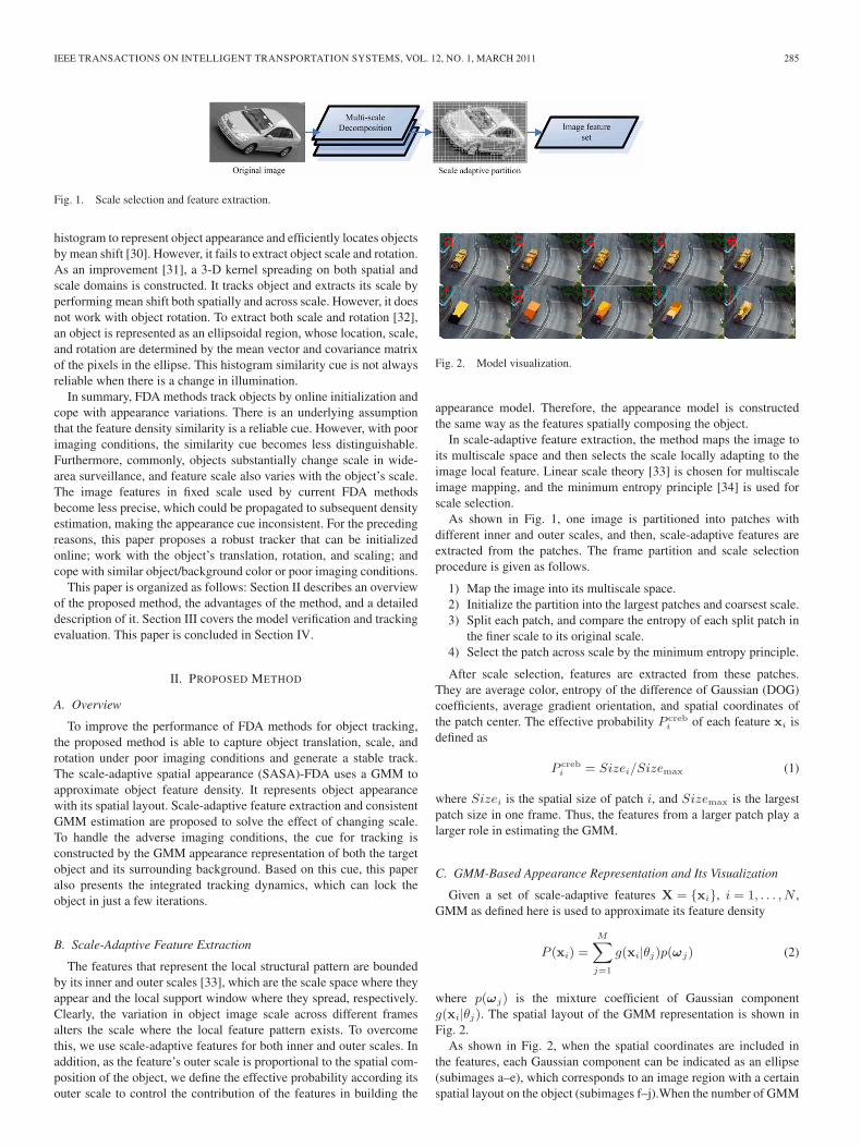
Fig. 1. Scale selection and feature extraction.
histogram to represent object appearance and efficiently locates objectsby mean shift [30]. However, it fails to extract object scale and rotation.As an improvement [31], a 3-D kernel spreading on both spatial andscale domains is constructed. It tracks object and extracts its scale byperforming mean shift both spatially and across scale. However, it doesnot work with object rotation. To extract both scale and rotation [32],an object is represented as an ellipsoidal region, whose location, scale,and rotation are determined by the mean vector and covariance matrixof the pixels in the ellipse. This histogram similarity cue is not alwaysreliable when there is a change in illumination.
In summary, FDA methods track objects by online initialization andcope with appearance variations. There is an underlying assumptionthat the feature density similarity is a reliable cue. However, with poorimaging conditions, the similarity cue becomes less distinguishable.Furthermore, commonly, objects substantially change scale in wide-area surveillance, and feature scale also varies with the object’s scale.The image features in fixed scale used by current FDA methodsbecome less precise, which could be propagated to subsequent densityestimation, making the appearance cue inconsistent. For the precedingreasons, this paper proposes a robust tracker that can be initializedonline; work with the object’s translation, rotation, and scaling; andcope with similar object/background color or poor imaging conditions.
This paper is organized as follows: Section II describes an overviewof the proposed method, the advantages of the method, and a detaileddescription of it. Section III covers the model verification and trackingevaluation. This paper is concluded in Section IV.
II. PROPOSED METHOD
A. Overview
To improve the performance of FDA methods for object tracking,the proposed method is able to capture object translation, scale, androtation under poor imaging conditions and generate a stable track.The scale-adaptive spatial appearance (SASA)-FDA uses a GMM toapproximate object feature density. It represents object appearancewith its spatial layout. Scale-adaptive feature extraction and consistentGMM estimation are proposed to solve the effect of changing scale.To handle the adverse imaging conditions, the cue for tracking isconstructed by the GMM appearance representation of both the targetobject and its surrounding background. Based on this cue, this paperalso presents the integrated tracking dynamics, which can lock theobject in just a few iterations.
B. Scale-Adaptive Feature Extraction
The features that represent the local structural pattern are boundedby its inner and outer scales [33], which are the scale space where theyappear and the local support window where they spread, respectively.Clearly, the variation in object image scale across different framesalters the scale where the local feature pattern exists. To overcomethis, we use scale-adaptive features for both inner and outer scales. Inaddition, as the feature’s outer scale is proportional to the spatial com-position of the object, we define the effective probability according itsouter scale to control the contribution of the features in building the
Fig. 2. Model visualization.
appearance model. Therefore, the appearance model is constructedthe same way as the features spatially composing the object.
In scale-adaptive feature extraction, the method maps the image toits multiscale space and then selects the scale locally adapting to theimage local feature. Linear scale theory [33] is chosen for multiscaleimage mapping, and the minimum entropy principle [34] is used forscale selection.
As shown in Fig. 1, one image is partitioned into patches withdifferent inner and outer scales, and then, scale-adaptive features areextracted from the patches. The frame partition and scale selectionprocedure is given as follows.
1) Map the image into its multiscale space.2) Initialize the partition into the largest patches and coarsest scale.3) Split each patch, and compare the entropy of each split patch in
the finer scale to its original scale.4) Select the patch across scale by the minimum entropy principle.
After scale selection, features are extracted from these patches.They are average color, entropy of the difference of Gaussian (DOG)coefficients, average gradient orientation, and spatial coordinates ofthe patch center. The effective probability P creb
i of each feature xi isdefined as
P crebi = Sizei/Sizemax (1)
where Sizei is the spatial size of patch i, and Sizemax is the largestpatch size in one frame. Thus, the features from a larger patch play alarger role in estimating the GMM.
C. GMM-Based Appearance Representation and Its Visualization
Given a set of scale-adaptive features X = {xi}, i = 1, . . . , N ,GMM as defined here is used to approximate its feature density
P (xi) =
M∑j=1
g(xi|θj)p(ωj) (2)
where p(ωj) is the mixture coefficient of Gaussian componentg(xi|θj). The spatial layout of the GMM representation is shown inFig. 2.
As shown in Fig. 2, when the spatial coordinates are included inthe features, each Gaussian component can be indicated as an ellipse(subimages a–e), which corresponds to an image region with a certainspatial layout on the object (subimages f–j).When the number of GMM

286 IEEE TRANSACTIONS ON INTELLIGENT TRANSPORTATION SYSTEMS, VOL. 12, NO. 1, MARCH 2011
components is chosen as 2, 3, 4, 5, and 20, the object representationhas a different degree of detail.
D. Consistent GMM-Based FDA With Feature Effective Probability
To improve the FDA accuracy, we equal the contribution of thefeatures in FDA to the proportions in which their patch composes theobject. To achieve this, the log likelihood function is defined by boththe feature set {xi} and the effective probability {P creb
i } as
L(θ) = log
N∏i=1
P (xi, zi;θ)P crebi
= log
N∏i=1
M∏j=1
[P (xi|zij = 1;θ)P (zij = 1)P creb
i
]zij (3)
where zi = [zi1, . . . , ziM ]T , and zij = {1, 0} indicates that xi isgenerated by which Gaussian components. The EM algorithm forGMM estimate with the effective probability P creb is
E − step :
hij = E[zij |xi, θk] = p(ωj)g(xi|θj)/
M∑l=1
p(ωj)g(xi|θl) (4)
M − step :
p(ωj) =
N∑i=1
hijPcrebi
N∑i=1
P crebi
μk+1j =
N∑i=1
hijxiPcrebi
N∑i=1
hijP crebi
k+1∑j
=
N∑i=1
hij
(xi − μk+1
j
) (xi − μk+1
j
)TP creb
i
N∑i=1
hijP crebi
(5)
where g(xi|θl) is one Gaussian component in (2).Fig. 3 provides an illustration of the role of P creb in GMM estima-
tion. Subimage (a) is the test image, and its intensity is used for GMMestimation. Subimage (b) shows the result of scale-adaptive featureextraction where the test image is partitioned into image patches ofdifferent sizes (outer scale), the patch mean intensity is used as itsfeature, and the effective probability is defined by its size. The GMMestimation based on the patch mean intensity should be similar to theimage histogram [as shown in (c)]. In (d), the GMM estimation withoutthe effective probability is shown, whereas (e) is the GMM estimationwith effective probability. Clearly, without effective probability [in(d)], the estimate is driven to the brighter ones, as they have a largerpatch number, in spite of composing a small part in the image. In (e),the features contribute according to their effective probability, and theestimate is closer to the histogram.
E. WLR Cue for Tracking and the Tracking Dynamics
When the object and its surrounding are similar in appearance,the object image feature contains overlapping distribution with itssurrounding. It makes the tracking result oscillatory. To solve theproblem, a notion of the surrounding background is necessary. Basedon this idea, we construct the tracking image cue as a weighted loglikelihood ratio (WLR) by both the object GMM and its surroundingGMM. The object is located by searching the maximum WLR region.
To associate the object appearance model with its location, a spatialkernel is used to weigh the feature’s likelihood ratio, and the objectbounding window can be driven from an initial location ms to the
Fig. 3. Model estimation with feature effective probability.
WLR location μs in a gradient-based search. As such, the trackingproblem can be formulated as the optimization problem
μs = arg maxms
{Cms =
∑xi∈Xms
log
[Lobj(xi|ms)
Lbc(xi|ms)
]
· K (|si −ms|)}
(6)
where Cms is the cost function defined by the WLR, μs is theoptimum bounding window location to be determined, Xms is thefeature set from the current bounding window centered in ms, and si
is the spatial coordinates of each feature vector xi. Lobj(·) and Lbc(·)are the log likelihoods of a feature evaluated on the object GMM andits surrounding GMM, respectively, and K(|si −ms|) is the spatialkernel defined as
K (|si −ms|) = bs − (si −ms)T Σ−1
s (si −ms) (7)
where bs is the normalizing constant to make the kernel nonnegative,and Σs is a positive-definite matrix estimated from the size of thecurrent bounding window. The derivative of the kernel is linear toobject motion. The optimization problem can be solved by setting thederivative of Cms to zero w.r.t. to ms, which is
∇Cms =∑
xi∈Xms
{log [Lobj(xi|ms)] − log [Lbc(xi|ms)]}
·[Σ−1
s (si −ms)]. (8)
Setting ∇Cms to zeros, the current optimum location μs is
μs =
∑xi∈Xms
si · {log [Lobj(xi|ms)] − log [Lbc(xi|ms)]}∑xi∈Xms
{log [Lobj(xi|ms)] − log [Lbc(xi|ms)]} . (9)
In (9), the log likelihood is evaluated on (3).In summary, given a GMM density appearance model and a current
starting location of the bounding window, we can estimate the nextbest location from the features within the current bounding windowaccording to (9).
Fig. 4 shows the tracking dynamics and WLR in the boundingwindow per iteration from an initial location to the maximum WLRlocation. a1–a4 are the locations of the bounding window at each

IEEE TRANSACTIONS ON INTELLIGENT TRANSPORTATION SYSTEMS, VOL. 12, NO. 1, MARCH 2011 287
Fig. 4. Tracking dynamics.
iteration, b1–b4 show the WLR, and the total WLR in the boundingwindow is shown in blue. As shown in a1, the initial location of thebounding window is away from the object. In subsequent evaluations,the object features have larger WLR value than the background;thus, the bounding window is driven toward the object. After fouriterations, the bounding window locked the object, and the WLRreaches the maximum.
Fig. 5 compares the effectiveness of the proposed WLR cue with theHistogram Bhattacharyya Coefficient Distance (HBCD) w.r.t. trans-lation, rotation, and scaling. The learning and testing are conductedon frames with 20 intervals. As indicated by sub-Fig. 1, both thehistogram and the object/surrounding GMM are learned in the redellipse region. Testing is conducted on the frame in sub-Fig. 2, andthe ground truth is also marked by the red ellipse. In sub-Figs. 3 and4, the performance of the tracking cue w.r.t. translation is compared.The surface is generated by sliding the bounding window in the range[−30 : 30, −50 : 50] along the x- and y-directions, respectively. Thematching at each bounding window location to the target is measuredby both the HBCD cue and the total WLR. As such, matching surfacesare generated in sub-Fig. 3 for the HBCD cue and in sub-Fig. 4 for thetotal WLR cue. When surfaces peak at the ground truth location(0,0),the WLR cue is unimodal with one global maximum, which indicatesa stronger discrimination. In sub-Figs. 5 and 6, the performance of thetracking cue w.r.t. rotation is compared. The surface is generated byrotating the bounding window in the range [−50◦, 50◦]. As shown, theWLR cue also has a smaller rotational deviation and sharper matchingcurve. Moreover, it has fewer local minimum points. In sub-Figs. 7and 8, the performance of the tracking cue w.r.t. scale is compared.The surface is generated by scaling the bounding window in the range[70%, 130%] to the scale of ground truth. They demonstrated thesame property. For the histogram Bhattacharyya coefficient cue, whenthe scale is smaller than the ground truth, the curve is flatter, whichindicates that the smaller scale with no background included tends tobe selected. Table I summarizes the deviation in the preceding threecomparisons.
F. Rotation and Scale Adaptation
To capture the object heading angle (rotation) and scaling, rotationand scaling adaptation are applied to the object bounding window afterit has been localized. Then, the rotation and scale factor [φ, δ] with the
Fig. 5. Performance of tracking cue.
TABLE ICOMPARISON FOR TRACKING CUES
largest total WLR is selected for the bounding window. For vehiclescaptured in the 25-frames/s video, the empirical range φ ∈ [−5◦, 5◦]and δ ∈ [0.95, 1.05] are large enough to cover all possible values.
III. EXPERIMENTS AND DISCUSSION
A. Choice of Color Space
In the experiment, the L∗a∗b color space is chosen. The commonchoices include RGB and HSV space as well. However, RGB is proneto be affected by illumination. HSV and L∗a∗b both decouple illumi-nation from chromatic information and, thus, offer higher consistency.Although HSV outperforms L∗a∗b in [35], it is unreliable for low-saturation colors. Moreover, HSV colors outside certain V and Sranges are normally discarded for stability. On comparison, L∗a∗boffers more stability across illumination and saturation ranges.
288 IEEE TRANSACTIONS ON INTELLIGENT TRANSPORTATION SYSTEMS, VOL. 12, NO. 1, MARCH 2011
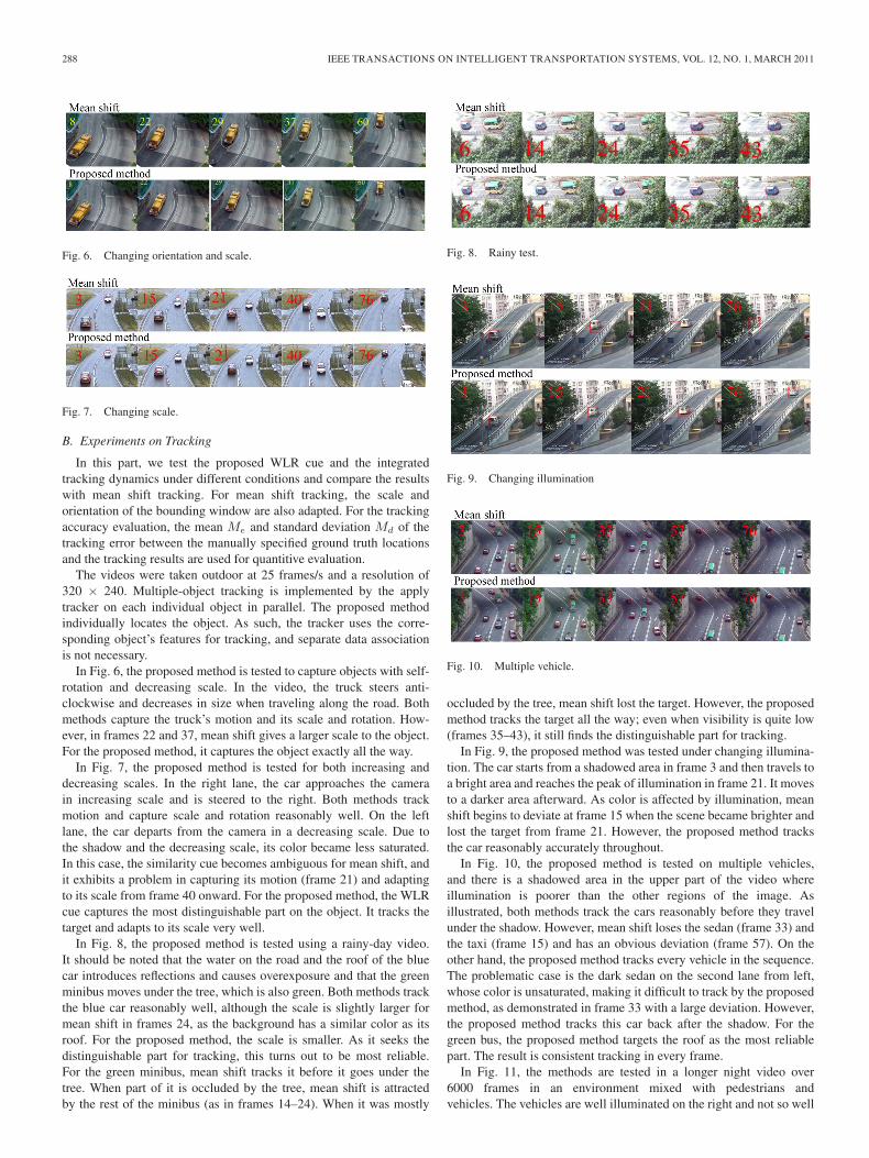
Fig. 6. Changing orientation and scale.
Fig. 7. Changing scale.
B. Experiments on Tracking
In this part, we test the proposed WLR cue and the integratedtracking dynamics under different conditions and compare the resultswith mean shift tracking. For mean shift tracking, the scale andorientation of the bounding window are also adapted. For the trackingaccuracy evaluation, the mean Me and standard deviation Md of thetracking error between the manually specified ground truth locationsand the tracking results are used for quantitive evaluation.
The videos were taken outdoor at 25 frames/s and a resolution of320 × 240. Multiple-object tracking is implemented by the applytracker on each individual object in parallel. The proposed methodindividually locates the object. As such, the tracker uses the corre-sponding object’s features for tracking, and separate data associationis not necessary.
In Fig. 6, the proposed method is tested to capture objects with self-rotation and decreasing scale. In the video, the truck steers anti-clockwise and decreases in size when traveling along the road. Bothmethods capture the truck’s motion and its scale and rotation. How-ever, in frames 22 and 37, mean shift gives a larger scale to the object.For the proposed method, it captures the object exactly all the way.
In Fig. 7, the proposed method is tested for both increasing anddecreasing scales. In the right lane, the car approaches the camerain increasing scale and is steered to the right. Both methods trackmotion and capture scale and rotation reasonably well. On the leftlane, the car departs from the camera in a decreasing scale. Due tothe shadow and the decreasing scale, its color became less saturated.In this case, the similarity cue becomes ambiguous for mean shift, andit exhibits a problem in capturing its motion (frame 21) and adaptingto its scale from frame 40 onward. For the proposed method, the WLRcue captures the most distinguishable part on the object. It tracks thetarget and adapts to its scale very well.
In Fig. 8, the proposed method is tested using a rainy-day video.It should be noted that the water on the road and the roof of the bluecar introduces reflections and causes overexposure and that the greenminibus moves under the tree, which is also green. Both methods trackthe blue car reasonably well, although the scale is slightly larger formean shift in frames 24, as the background has a similar color as itsroof. For the proposed method, the scale is smaller. As it seeks thedistinguishable part for tracking, this turns out to be most reliable.For the green minibus, mean shift tracks it before it goes under thetree. When part of it is occluded by the tree, mean shift is attractedby the rest of the minibus (as in frames 14–24). When it was mostly
Fig. 8. Rainy test.
Fig. 9. Changing illumination
Fig. 10. Multiple vehicle.
occluded by the tree, mean shift lost the target. However, the proposedmethod tracks the target all the way; even when visibility is quite low(frames 35–43), it still finds the distinguishable part for tracking.
In Fig. 9, the proposed method was tested under changing illumina-tion. The car starts from a shadowed area in frame 3 and then travels toa bright area and reaches the peak of illumination in frame 21. It movesto a darker area afterward. As color is affected by illumination, meanshift begins to deviate at frame 15 when the scene became brighter andlost the target from frame 21. However, the proposed method tracksthe car reasonably accurately throughout.
In Fig. 10, the proposed method is tested on multiple vehicles,and there is a shadowed area in the upper part of the video whereillumination is poorer than the other regions of the image. Asillustrated, both methods track the cars reasonably before they travelunder the shadow. However, mean shift loses the sedan (frame 33) andthe taxi (frame 15) and has an obvious deviation (frame 57). On theother hand, the proposed method tracks every vehicle in the sequence.The problematic case is the dark sedan on the second lane from left,whose color is unsaturated, making it difficult to track by the proposedmethod, as demonstrated in frame 33 with a large deviation. However,the proposed method tracks this car back after the shadow. For thegreen bus, the proposed method targets the roof as the most reliablepart. The result is consistent tracking in every frame.
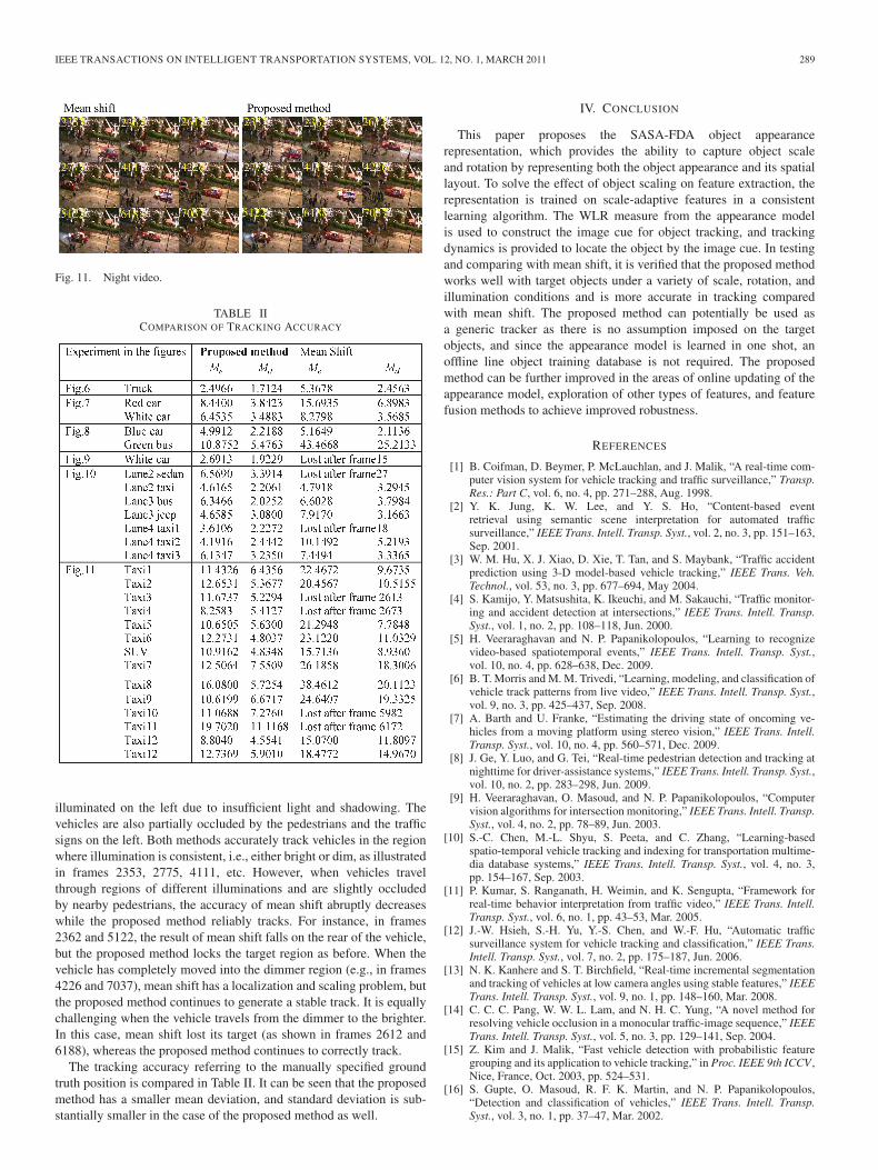
In Fig. 11, the methods are tested in a longer night video over6000 frames in an environment mixed with pedestrians andvehicles. The vehicles are well illuminated on the right and not so well
IEEE TRANSACTIONS ON INTELLIGENT TRANSPORTATION SYSTEMS, VOL. 12, NO. 1, MARCH 2011 289
Fig. 11. Night video.
TABLE IICOMPARISON OF TRACKING ACCURACY
illuminated on the left due to insufficient light and shadowing. Thevehicles are also partially occluded by the pedestrians and the trafficsigns on the left. Both methods accurately track vehicles in the regionwhere illumination is consistent, i.e., either bright or dim, as illustratedin frames 2353, 2775, 4111, etc. However, when vehicles travelthrough regions of different illuminations and are slightly occludedby nearby pedestrians, the accuracy of mean shift abruptly decreaseswhile the proposed method reliably tracks. For instance, in frames2362 and 5122, the result of mean shift falls on the rear of the vehicle,but the proposed method locks the target region as before. When thevehicle has completely moved into the dimmer region (e.g., in frames4226 and 7037), mean shift has a localization and scaling problem, butthe proposed method continues to generate a stable track. It is equallychallenging when the vehicle travels from the dimmer to the brighter.In this case, mean shift lost its target (as shown in frames 2612 and6188), whereas the proposed method continues to correctly track.
The tracking accuracy referring to the manually specified groundtruth position is compared in Table II. It can be seen that the proposedmethod has a smaller mean deviation, and standard deviation is sub-stantially smaller in the case of the proposed method as well.
IV. CONCLUSION
This paper proposes the SASA-FDA object appearancerepresentation, which provides the ability to capture object scaleand rotation by representing both the object appearance and its spatiallayout. To solve the effect of object scaling on feature extraction, therepresentation is trained on scale-adaptive features in a consistentlearning algorithm. The WLR measure from the appearance modelis used to construct the image cue for object tracking, and trackingdynamics is provided to locate the object by the image cue. In testingand comparing with mean shift, it is verified that the proposed methodworks well with target objects under a variety of scale, rotation, andillumination conditions and is more accurate in tracking comparedwith mean shift. The proposed method can potentially be used asa generic tracker as there is no assumption imposed on the targetobjects, and since the appearance model is learned in one shot, anoffline line object training database is not required. The proposedmethod can be further improved in the areas of online updating of theappearance model, exploration of other types of features, and featurefusion methods to achieve improved robustness.
REFERENCES
[1] B. Coifman, D. Beymer, P. McLauchlan, and J. Malik, “A real-time com-puter vision system for vehicle tracking and traffic surveillance,” Transp.Res.: Part C, vol. 6, no. 4, pp. 271–288, Aug. 1998.
[2] Y. K. Jung, K. W. Lee, and Y. S. Ho, “Content-based eventretrieval using semantic scene interpretation for automated trafficsurveillance,” IEEE Trans. Intell. Transp. Syst., vol. 2, no. 3, pp. 151–163,Sep. 2001.
[3] W. M. Hu, X. J. Xiao, D. Xie, T. Tan, and S. Maybank, “Traffic accidentprediction using 3-D model-based vehicle tracking,” IEEE Trans. Veh.Technol., vol. 53, no. 3, pp. 677–694, May 2004.
[4] S. Kamijo, Y. Matsushita, K. Ikeuchi, and M. Sakauchi, “Traffic monitor-ing and accident detection at intersections,” IEEE Trans. Intell. Transp.Syst., vol. 1, no. 2, pp. 108–118, Jun. 2000.
[5] H. Veeraraghavan and N. P. Papanikolopoulos, “Learning to recognizevideo-based spatiotemporal events,” IEEE Trans. Intell. Transp. Syst.,vol. 10, no. 4, pp. 628–638, Dec. 2009.
[6] B. T. Morris and M. M. Trivedi, “Learning, modeling, and classification ofvehicle track patterns from live video,” IEEE Trans. Intell. Transp. Syst.,vol. 9, no. 3, pp. 425–437, Sep. 2008.
[7] A. Barth and U. Franke, “Estimating the driving state of oncoming ve-hicles from a moving platform using stereo vision,” IEEE Trans. Intell.Transp. Syst., vol. 10, no. 4, pp. 560–571, Dec. 2009.
[8] J. Ge, Y. Luo, and G. Tei, “Real-time pedestrian detection and tracking atnighttime for driver-assistance systems,” IEEE Trans. Intell. Transp. Syst.,vol. 10, no. 2, pp. 283–298, Jun. 2009.
[9] H. Veeraraghavan, O. Masoud, and N. P. Papanikolopoulos, “Computervision algorithms for intersection monitoring,” IEEE Trans. Intell. Transp.Syst., vol. 4, no. 2, pp. 78–89, Jun. 2003.
[10] S.-C. Chen, M.-L. Shyu, S. Peeta, and C. Zhang, “Learning-basedspatio-temporal vehicle tracking and indexing for transportation multime-dia database systems,” IEEE Trans. Intell. Transp. Syst., vol. 4, no. 3,pp. 154–167, Sep. 2003.
[11] P. Kumar, S. Ranganath, H. Weimin, and K. Sengupta, “Framework forreal-time behavior interpretation from traffic video,” IEEE Trans. Intell.Transp. Syst., vol. 6, no. 1, pp. 43–53, Mar. 2005.
[12] J.-W. Hsieh, S.-H. Yu, Y.-S. Chen, and W.-F. Hu, “Automatic trafficsurveillance system for vehicle tracking and classification,” IEEE Trans.Intell. Transp. Syst., vol. 7, no. 2, pp. 175–187, Jun. 2006.
[13] N. K. Kanhere and S. T. Birchfield, “Real-time incremental segmentationand tracking of vehicles at low camera angles using stable features,” IEEETrans. Intell. Transp. Syst., vol. 9, no. 1, pp. 148–160, Mar. 2008.
[14] C. C. C. Pang, W. W. L. Lam, and N. H. C. Yung, “A novel method forresolving vehicle occlusion in a monocular traffic-image sequence,” IEEETrans. Intell. Transp. Syst., vol. 5, no. 3, pp. 129–141, Sep. 2004.
[15] Z. Kim and J. Malik, “Fast vehicle detection with probabilistic featuregrouping and its application to vehicle tracking,” in Proc. IEEE 9th ICCV ,Nice, France, Oct. 2003, pp. 524–531.
[16] S. Gupte, O. Masoud, R. F. K. Martin, and N. P. Papanikolopoulos,“Detection and classification of vehicles,” IEEE Trans. Intell. Transp.Syst., vol. 3, no. 1, pp. 37–47, Mar. 2002.

290 IEEE TRANSACTIONS ON INTELLIGENT TRANSPORTATION SYSTEMS, VOL. 12, NO. 1, MARCH 2011
[17] Y. Huang, T. S. Huang, and H. Niemann, “A region-based method formodel-free object tracking,” in Proc. 9th ICPR, Quebec City, QC, Canada,Aug. 2002, pp. 592–595.
[18] D. A. Ross, J. Lim, R.-S. Lin, and M.-H. Yang, “Incremental learning forrobust visual tracking,” Int. J. Comput. Vis., vol. 77, no. 1–3, pp. 125–141,May 2008.
[19] C.-C. R. Wang and J.-J. J. Lien, “Automatic vehicle detection using localfeatures—A statistical approach,” IEEE Trans. Intell. Transp. Syst., vol. 9,no. 1, pp. 83–96, Mar. 2008.
[20] T. Xiong and C. Debrunner, “Stochastic car tracking with line- andcolor-based features,” IEEE Trans. Intell. Transp. Syst., vol. 5, no. 4,pp. 324–328, Dec. 2004.
[21] S. Munder, C. Schnörr, and D. M. Gavrila, “Pedestrian detection andtracking using a mixture of view-based shape–texture models,” IEEETrans. Intell. Transp. Syst., vol. 9, no. 2, pp. 333–343, Jun. 2008.
[22] F. Xu, X. Liu, and K. Fujimura, “Pedestrian detection and tracking withnight vision,” IEEE Trans. Intell. Transp. Syst., vol. 6, no. 1, pp. 63–71,Mar. 2005.
[23] S. Sivaraman and M. M. Trivedi, “A general active-learning frameworkfor on-road vehicle recognition and tracking,” IEEE Trans. Intell. Transp.Syst., vol. 11, no. 2, pp. 267–276, Jun. 2010.
[24] R. O’Malley, E. Jones, and M. Glavin, “Rear-lamp vehicle detection andtracking in low-exposure color video for night conditions,” IEEE Trans.Intell. Transp. Syst., vol. 11, no. 2, pp. 453–462, Jun. 2010.
[25] L. Oliveira, U. Nunes, and P. Peixoto, “On exploration of classifierensemble synergism in pedestrian detection,” IEEE Trans. Intell. Transp.Syst., vol. 11, no. 1, pp. 16–27, Mar. 2010.
[26] H. Wang, D. Suter, K. Schindler, and C. Shen, “Adaptive object trackingbased on an effective appearance filter,” IEEE Trans. Pattern Anal. Mach.Intell., vol. 29, no. 9, pp. 1661–1667, Sep. 2007.
[27] A. P. Dempster, N. M. Laird, and D. B. Rubin, “Maximum likelihood fromincomplete data via the EM algorithm,” J. R. Stat. Soc., Ser. B, vol. 39,no. 1, pp. 1–38, 1977.
[28] B. Han, D. Comaniciu, Y. Zhu, and L. S. Davis, “Sequential kerneldensity approximation and its application to real-time visual tracking,”IEEE Trans. Pattern Anal. Mach. Intell., vol. 30, no. 7, pp. 1186–1197,Jul. 2008.
[29] D. Comaniciu, V. Ramesh, and P. Meer, “Kernel-based object tracking,”IEEE Trans. Pattern Anal. Mach. Intell., vol. 25, no. 5, pp. 564–577,May 2003.
[30] D. Comaniciu and P. Meer, “Mean shift: A robust approach toward featurespace analysis,” IEEE Trans. Pattern Anal. Mach. Intell., vol. 24, no. 5,pp. 603–619, May 2002.
[31] R. Collins, “Mean-shift blob tracking through scale space,” in Proc. IEEEConf. CVPR, Madison, WI, 2003, pp. 234–240.
[32] Z. Zivkovic and B. Kröse, “An EM-like algorithm for color-histogram-based object tracking,” in Proc. IEEE Conf. CVPR, Washington, DC,2004, pp. 798–803.
[33] T. Lindeberg, Scale-Space Theory in Computer Vision. Dordrecht, TheNetherlands: Kluwer, 1994, pp. 101–149.
[34] T. Kadir and M. Brady, “Saliency, scale and image description,” Int. J.Comput. Vis., vol. 45, no. 2, pp. 83–105, Nov. 2001.
[35] E. Maggio and A. Cavallaro, “Multi-part target representation for colourtracking,” in Proc. IEEE ICIP, Genoa, Italy, 2005, pp. 729–732.