austroads (2002), mix design for stabilised pavement materials
DESCRIPTION
Austroads (2002), Mix Design for Stabilised Pavement MaterialsTRANSCRIPT

AP-T16
AUSTROADS
MIX DESIGN FOR STABILISED PAVEMENT MATERIALS
Mix Design For Stabilised Pavement Materials First Published 2002
© Austroads Inc. 2002
This work is copyright. Apart from any use as permitted under the Copyright Act 1968, no part may be reproduced by any process without the prior written permission of Austroads.
National Library of Australia Cataloguing-in-Publication data:
Mix Design For Stabilised Pavement Materials ISBN 0 85588 616 1
Austroads Project No. T&E.P.N.516
Austroads Publication No. AP-T16/02
Project Manager
Mr George Vorobieff Australian Stabilisation Industry Association (AustStab)
Prepared by
Mr Graham Foley, ARRB TR Austroads Stabilisation Expert Group
Published by Austroads Incorporated Level 9, Robell House 287 Elizabeth Street
Sydney NSW 2000 Australia Phone: +61 2 9264 7088
Fax: +61 2 9264 1657 Email: [email protected]
www.austroads.com.au
Austroads believes this publication to be correct at the time of printing and does not accept responsibility for any consequences arising from the use of information herein. Readers should rely on their own skill and
judgement to apply information to particular issues.

MIX DESIGN FOR STABILISED
PAVEMENT MATERIALS
Sydney 2002

AUSTROADS PROFILE
Austroads is the association of Australian and New Zealand road transport and traffic authorities whose purpose is to contribute to the achievement of improved Australian and New Zealand transport related outcomes by: ♦ developing and promoting best practice for the safe and effective management and use of the road
system ♦ providing professional support and advice to member organisations and national and international
bodies ♦ acting as a common vehicle for national and international action ♦ fulfilling the role of the Australian Transport Council’s Road Modal Group ♦ undertaking performance assessment and development of Australian and New Zealand standards ♦ developing and managing the National Strategic Research Program for roads and their use. Within this ambit, Austroads aims to provide strategic direction for the integrated development, management and operation of the Australian and New Zealand road system — through the promotion of national uniformity and harmony, elimination of unnecessary duplication, and the identification and application of world best practice.
AUSTROADS MEMBERSHIP
Austroads membership comprises the six State and two Territory road transport and traffic authorities and the Commonwealth Department of Transport and Regional Services in Australia, the Australian Local Government Association and Transit New Zealand. It is governed by a council consisting of the chief executive officer (or an alternative senior executive officer) of each of its eleven member organisations: ♦ Roads and Traffic Authority New South Wales ♦ Roads Corporation Victoria ♦ Department of Main Roads Queensland ♦ Main Roads Western Australia ♦ Transport South Australia ♦ Department of Infrastructure, Energy and Resources Tasmania ♦ Department of Infrastructure, Planning and Environment Northern Territory ♦ Department of Urban Services Australian Capital Territory ♦ Commonwealth Department of Transport and Regional Services ♦ Australian Local Government Association ♦ Transit New Zealand The success of Austroads is derived from the synergies of interest and participation of member organisations and others in the road industry.
ACKNOWLEDGMENT
Thanks to the information, time, collection of test data and experience of the following gents who have provided the foundation for this body of work. Austroads Stabilisation Expert Group: 1999-2001
Mr George Vorobieff (Convenor), Australian Stabilisation Industry Association (AustStab)
Mr Phil Walter, Roads and Traffic Authority, New South Wales
Mr Andrew Papacostas, VicRoads, Victoria
Mr Jothi Ramanujam, Queensland Department of Main Roads
Mr Bob Andrews & Mr David Hazell, Transport South Australia
Mr Graham Foley & Mr Allan Alderson, ARRB Transport Research
Mr Phil Gallagher, AAPA
Mr Frank Butkus, Main Roads, Western Australia
Corresponding Members:
Mr Mark Symons, representing the University of South Australia
Dr Jayantha Kodikara, representing the University of Victoria

EXECUTIVE SUMMARY Introduction The aim of project N.T&E.9910 Improved Characterisation and Specification of Stabilised Quarried and Recycled Materials is to improve knowledge of the most appropriate way to characterise stabilised quarry and recycled materials in order that the most reliable and cost-effective options are selected and incorporated into practice.
During 2001, Project N.T&E.9910 produced reports, which addressed the following issues: • performance criteria for various stabilised materials, • draft guidelines for the selection of the most appropriate binder type and binder content (mix design),
and • factors affecting the long-term performance of stabilised materials. Mix design and basic binder selection criteria are addressed by this report encompassing flowcharts and accompanying notes for various design considerations for the laboratory testing of stabilised pavement materials. This is the first known publication in Australia detailing laboratory test procedures to optimise the binder selection and application rate, and addressing the issues faced by practitioners in regard to subgrade conditions. The flowcharts are aimed at roads with medium to heavy traffic, and are unlikely to be used on lightly trafficked streets. These flowcharts have been produced for: • site inspection and assessment for insitu stabilisation, • modification of pavement materials using cementitious binders, and • heavily bound pavement materials using cementitious binders. • lime stabilisation and modification, and • foamed bitumen stabilisation. Appendix D includes a flow chart for lime modification adapted from Victorian experience. Separate sheets of notes accompany the flowcharts. These provide guidance on the following testing procedures: • suggested grading limits for stabilisation, • determination of ‘adequate subgrade strength’, • unconfined compressive strength, • resilient modulus, • capillary rise, • drying shrinkage, and • erodability. It is envisaged that as a result of this report the information will be used in the proposed Austroads’ rehabilitation guide and by practitioners to provide suitable stabilisation solutions for road maintenance and new construction.

CONTENTS
1. INTRODUCTION ..........................................................................................................1 1.1 Project Aim ..........................................................................................................1 1.2 Background..........................................................................................................1
2. DESIGN FLOWCHARTS..............................................................................................2 2.1 Background..........................................................................................................2 2.2 Flowcharts and Notes Produced..........................................................................2 2.3 Flowcharts and the Pavement Design Process ...................................................2 2.4 Bound versus modified materials.........................................................................3 2.5 Types of binders and application rate..................................................................3 2.6 Material Grading Limits........................................................................................4 2.7 Minimum subgrade strength ................................................................................7 2.8 Unconfined compressive strength (UCS) ............................................................8 2.9 Resilient modulus ................................................................................................9 2.10 Capillary rise and swell ........................................................................................9 2.11 Erodability ............................................................................................................9
3. FLOWCHARTS AND NOTES ....................................................................................11
4. REFERENCES ...........................................................................................................21
5. BIBLIOGRAPHY OF RELEVANT AUSTRALIAN STANDARDS ..............................23
APPENDIX A — TEST METHODS FOR SUBGRADE STRENGTH ................................24
APPENDIX B — UCS TESTING IN REGIONAL AREAS .................................................26
APPENDIX C — DRYING SHRINKAGE...........................................................................28
APPENDIX D — LIME MODIFICATION ...........................................................................30
APPENDIX E — ACCELERATED CURING OF SAMPLES STABILISED WITH CEMENTITIOUS BINDERS...................................................................31

Mix Design for Stabilised Pavement Materials
A U S T R O A D S 2 0 0 2 1
1. INTRODUCTION
1.1 Project Aim The aim of project N.T&E.9910 Improved Characterisation and Specification of Stabilised Quarried and Recycled Materials is to improve knowledge of the most appropriate way to characterise stabilised quarry and recycled materials in order that the most reliable and cost-effective options are selected and incorporated into practice.
An important aim of the mix design process, the subject addressed within this report, is the need to carefully consider and plan testing requirements and resources at the early stages of the design process. Testing of materials and additives may consume substantial time and careful forethought is required to optimise the mix design process to maximise the performance of the pavement to be stabilised.
Pavement engineers have recognised that rehabilitation options are a careful balance of using scarce resources and funds, and application of technology. The flowcharts contained in this report provide a rational mix design approach leading to appropriate binders and application rates for stabilisation.
1.2 Background During the recent revision of the Austroads “Guide to Stabilisation in Roadworks”, which was published in 1998, several issues were identified which could not be resolved at that time but which demanded investigation to ensure that any future edition of, or amendments to, the Guide reflect the most up-to-date practice. Some of these issues included:
• the most appropriate mix design procedures for recycled materials incorporating stabilisation, • the curing regime, particularly the curing temperature and its influence on strength and
construction control, • the effect of binder type on performance, • the inherent variability in strength and density associated with this process, and • ideally, the development of generic performance models for these materials which could be based
on the design procedures currently recommended in the Austroads Pavement Design Guide but also take into account issues such as erosion at the interfaces of stabilised layers.
Given these issues, consideration should also be given to:
the increasing trend towards the re-use of lower-quality materials in pavements,
(a) the recent development of new and innovative stabilisers and construction processes such as deep lift insitu stabilisation, and
(b) the fact that the cost of the binder can represent up to half the cost of the design and construction of stabilised pavement layers, there is the potential for considerable cost savings through the development of procedures which allow the most appropriate, reliable and cost-effective options to be selected and adopted into practice.
During 2001, reports were issued which addressed the following issues:
• performance criteria for various stabilised materials, • draft guidelines for the selection of the most appropriate binder type and binder content, and • factors affecting the long-term performance of stabilised materials.
Mix design and basic binder selection criteria are addressed by this report encompassing flowcharts and accompanying notes for various design considerations for the laboratory testing of stabilised pavement materials.
It is envisaged that as a result of this report the information will be used in the proposed Austroads’ rehabilitation guide.
Mix Design for Stabilised Pavement Materials
2 A U S T R O A D S 2 0 0 2
2. DESIGN FLOWCHARTS
2.1 Background The Austroads’ Expert Group on Stabilised Pavements considered at its meetings in 1999/2000 that an appropriate output for the development of a rational approach for the mix design of stabilising treatment was to produce a suite of design flowcharts. During the development of these flowcharts it was seen that the following issues/items also required to be addressed:
• site selection flowchart to assist in determining the appropriateness of stabilisation as a rehabilitation technique, and
• brief notes to guide practitioners in the understanding and application of the testing procedures.
These issues have been addressed and comprise part of the ‘flowcharts’ in Section 3. Test methods pertaining specifically to stabilisation of pavement materials are currently under review.
2.2 Flowcharts and Notes Produced Flowcharts have been produced under this Contract for: • Site inspection and assessment for insitu stabilisation, Flowchart A. • Modification of pavement materials using cementitious binders, Flowchart B. • Lightly and heavy bound pavement materials using cementitious binders, Flowchart C. • Lime stabilisation, Flowchart D. Appendix D contains a flow chart of Victorian experience of
lime modification of pavement materials.
• Foamed bitumen stabilisation, Flowchart E.
Separate sheets of notes accompany the flowcharts. These provide guidance on the following test procedures:
• grading limits for selection of cementitious and bituminous stabilisation, • determination of ‘adequate subgrade strength’, • unconfined compressive strength, • resilient modulus, • capillary rise, and • erodability.
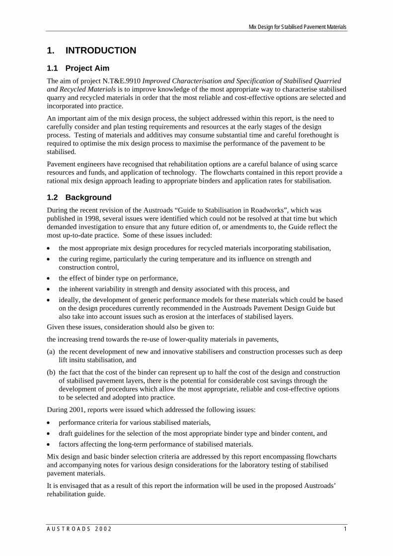
2.3 Flowcharts and the Pavement Design Process The flowcharts prepared under this contract may be used as input to the Austroads structural design system for pavements with stabilised layers as shown in Figure 1.
Mix Design for Stabilised Pavement Materials
A U S T R O A D S 2 0 0 2 3
Figure 1 — Austroads Structural Design System for Pavements with Stabilised Layers. (Austroads 1998)
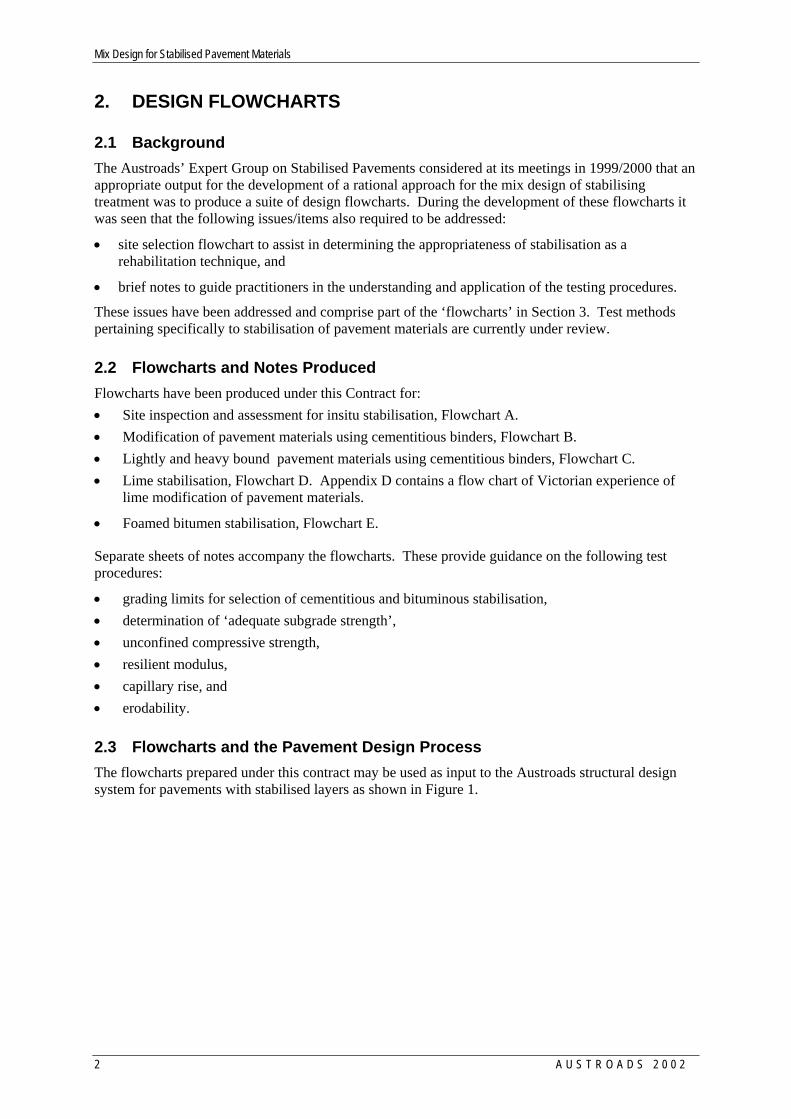
2.4 Bound versus modified materials Table 4.1 from Austroads (1998) is reproduced as Table 1 with amendments. Currently, various regions of Australia have adopted slightly different definitions for modified and bound stabilised materials and these are summarised in Appendix B.
Table 1 — Typical properties of modified, lightly bound and heavily bound materials.
Degree of Binding Design Strength (MPa) Design Flexural Modulus (MPa)
Modified UCS < 1.0 ≤ 1,000 Lightly bound UCS: 1-4 1,500 – 3,000 Heavily bound UCS > 4 ≥ 5,000
Notes:
1. 28 day test results, standard compaction and moist curing to AS 1141.51 2. For slow setting binders the 28 day test results will be less than the values shown but will
continue to increase in the field for at least 6 to 12 months
2.5 Types of binders and application rate Australian binder suppliers provide a variety of binders for various pavement materials. The basic binders used in stabilisation are: • Lime • Cementitious, GP & GB cement, blends of GGBFS1, fly ash, etc • Bitumen • Chemical polymers For more information about binders and their behaviour in soils refer to the Guide to Stabilisation in Roadworks (Austroads, 1998). Lime, cementitious and bitumen binders should conform to appropriate Australian Standards and the manufactures’ recommended product life.
1 GGBFS – Ground granulated blast furnance slag
Mix Design for Stabilised Pavement Materials
4 A U S T R O A D S 2 0 0 2
The most appropriate binder for various road pavements can be determined by the laboratory test described in the flowcharts. As an initial guide refer to Tables 2 and 3 respectively, which provide broad guidance on the boundaries of typical usages of various binder types.
The field application rate of the binder is specified by the mass of the binder per m2 of application area. This application rate in the laboratory, called the laboratory target rate, is based on the percentage of binder to the dry parent material by mass. Typically, testing is carried out at increments of 1% or sometimes 0.5%.
On a project, the density of the parent material may vary by up to ±20%. The designer should specify the range of MDD and the field application rate. The specifier may add 0.5% to the laboratory target rate, determined in the laboratory, to allow for variations in the spread rate in the field.
When using lime the quality of the lime should be determined for both the lime used in the laboratory and that in the works. The field application rate should be adjusted according to the ratio of the purity2 of lime to be used in the field. That is,
Adjusted field application rate = Field application rate
(field) limePurity (lab) limePurity
Where it is decided to use quicklime in place of hydrated lime, the application rate needs to be adjusted as follows:
Application rate (quicklime) = 0.76 x application rate (hydrated lime) 2.6 Material Grading Limits Various road building materials are sourced from quarries, borrow pits or even as recycled material from a previously stabilised pavement. It cannot be assumed that the grading of the material is suitable for stabilisation. The range of particle sizes for the pavement material shown in Table 4 and Figure 2 are suggested grading limits for bituminous binders. For lime and cementitious binders the grading limits are not as critical but will have an impact on the quantity of binder required to meet the desired strength or stiffness compared to a material that is well graded. VicRoads Specification 307 has recommended grading limits for materials suitable for stabilisation according to the PI of the parent material.
2 The purity of lime is defined as the available lime content calculated as calcium hydroxide (refer to AS 4489.6.1).
Mix Design for Stabilised Pavement Materials
A U S T R O A D S 2 0 0 2 5
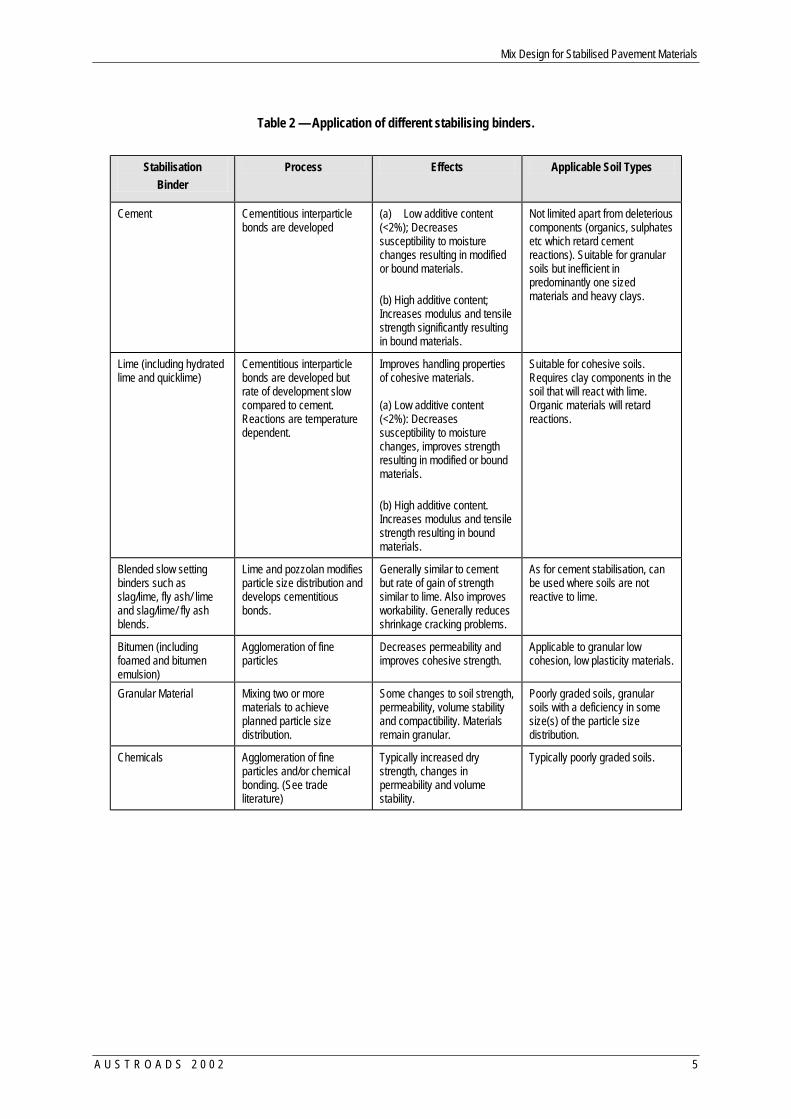
Table 2 — Application of different stabilising binders.
Stabilisation
Binder Process Effects Applicable Soil Types
Cement Cementitious interparticle bonds are developed
(a) Low additive content (<2%); Decreases susceptibility to moisture changes resulting in modified or bound materials. (b) High additive content; Increases modulus and tensile strength significantly resulting in bound materials.
Not limited apart from deleterious components (organics, sulphates etc which retard cement reactions). Suitable for granular soils but inefficient in predominantly one sized materials and heavy clays.
Lime (including hydrated lime and quicklime)
Cementitious interparticle bonds are developed but rate of development slow compared to cement. Reactions are temperature dependent.
Improves handling properties of cohesive materials. (a) Low additive content (<2%): Decreases susceptibility to moisture changes, improves strength resulting in modified or bound materials. (b) High additive content. Increases modulus and tensile strength resulting in bound materials.
Suitable for cohesive soils. Requires clay components in the soil that will react with lime. Organic materials will retard reactions.
Blended slow setting binders such as slag/lime, fly ash/ lime and slag/lime/ fly ash blends.
Lime and pozzolan modifies particle size distribution and develops cementitious bonds.
Generally similar to cement but rate of gain of strength similar to lime. Also improves workability. Generally reduces shrinkage cracking problems.
As for cement stabilisation, can be used where soils are not reactive to lime.
Bitumen (including foamed and bitumen emulsion)
Agglomeration of fine particles
Decreases permeability and improves cohesive strength.
Applicable to granular low cohesion, low plasticity materials.
Granular Material Mixing two or more materials to achieve planned particle size distribution.
Some changes to soil strength, permeability, volume stability and compactibility. Materials remain granular.
Poorly graded soils, granular soils with a deficiency in some size(s) of the particle size distribution.
Chemicals Agglomeration of fine particles and/or chemical bonding. (See trade literature)
Typically increased dry strength, changes in permeability and volume stability.
Typically poorly graded soils.

Mix Design for Stabilised Pavement Materials
6 A U S T R O A D S 2 0 0 2
Table 3 — A guide to the selection of binders for various PI values and content of fines (after Austroads 1998)
MORE THAN 25% PASSING 75µm
LESS THAN 25% PASSING 75µm
Plasticity Index
PI < 10
10 < PI <20
PI > 20
PI < 6 PI x % passing
75µm < 60
PI < 10
PI > 10
Form of Stabilisation
Cement and Cementitious Blends
����������������������������������������������������������
������
����������������������������������������
��������������������������������������������������������������������
Lime
������������������������������������������
��������
�����������������������������������
������������������������������������������������������
����������������������������������������������������������
��������
�������������������������������������������
����������������������������������������������������������������������
Bitumen
������������������������������������������
��������
�����������������������������������
������������������������������������������������������
����������������������������������������������������������
��������
�������������������������������������������
����������������������������������������������������������������������
����������������������������������������������������������
������
����������������������������������������
��������������������������������������������������������������������
Bitumen/ Cement Blends
����������������������������������������������������������
��������
�������������������������������������������
����������������������������������������������������������������������
����������������������������������������������������������
������
����������������������������������������
��������������������������������������������������������������������
Granular
����������������������������������������������������������
������
����������������������������������������
��������������������������������������������������������������������
Miscellaneous Chemicals*
����������������������������������������������������������
��������
�������������������������������������������
����������������������������������������������������������������������
Key
Usually suitable
Doubtful
����������������������������������������������������������
������
������������������������������������������
����������������������������������
Usually not Suitable
* Should be taken as a broad guideline only. Refer to trade literature for further definition. Foamed bitumen stabilisation is a process where foamed bitumen is incorporated into the mixing drum where it wets and coats the surface of the fine particles (i.e. less than 75µm in diameter) to form a stabilised pavement material, and therefore, sufficient fines are necessary for the process to be successful. Should there be insufficient fines in the pavement material, it may be possible to correct the grading by importing fines and dry mixing before incorporating the bitumen.
The flowcharts do not show the grading and PI requirements for laboratory testing, but it is implied in all cases.
Mix Design for Stabilised Pavement Materials
A U S T R O A D S 2 0 0 2 7
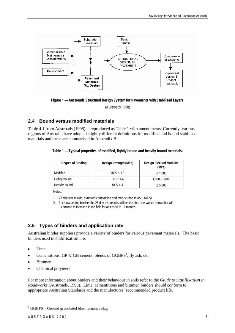
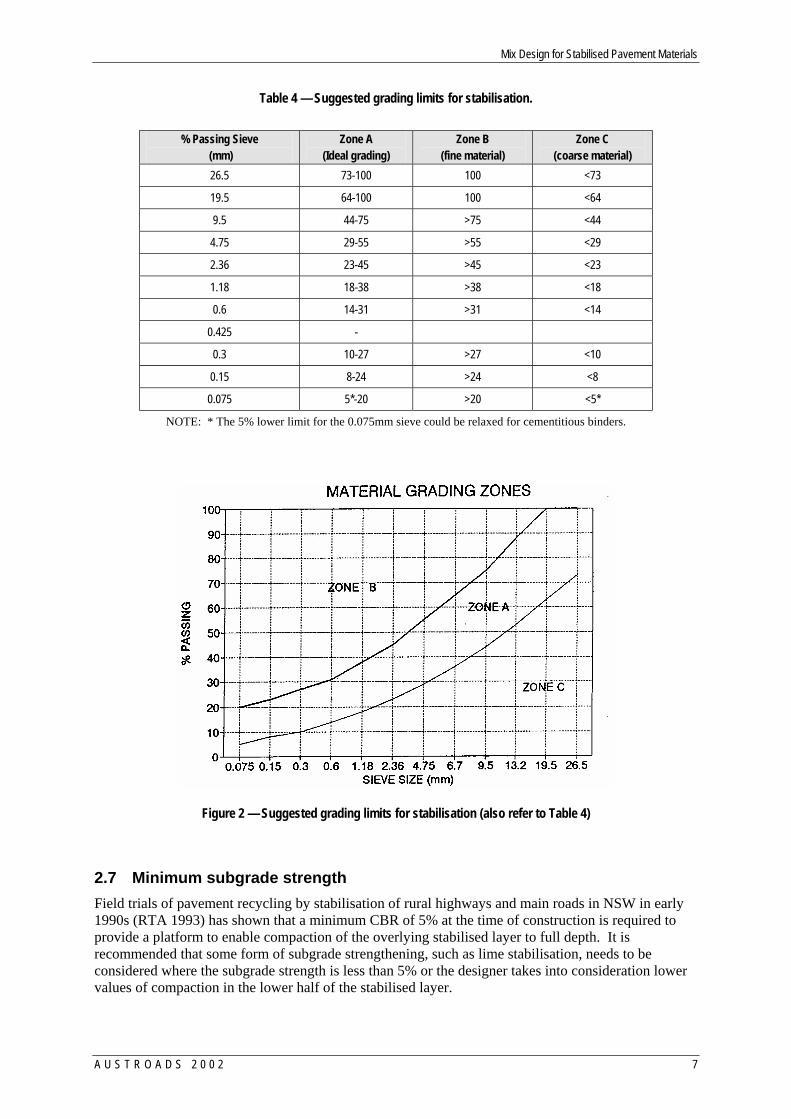
Table 4 — Suggested grading limits for stabilisation.
% Passing Sieve
(mm) Zone A
(Ideal grading) Zone B
(fine material) Zone C
(coarse material) 26.5 73-100 100 <73
19.5 64-100 100 <64
9.5 44-75 >75 <44
4.75 29-55 >55 <29
2.36 23-45 >45 <23
1.18 18-38 >38 <18
0.6 14-31 >31 <14
0.425 -
0.3 10-27 >27 <10
0.15 8-24 >24 <8
0.075 5*-20 >20 <5*
NOTE: * The 5% lower limit for the 0.075mm sieve could be relaxed for cementitious binders.
Figure 2 — Suggested grading limits for stabilisation (also refer to Table 4)
2.7 Minimum subgrade strength Field trials of pavement recycling by stabilisation of rural highways and main roads in NSW in early 1990s (RTA 1993) has shown that a minimum CBR of 5% at the time of construction is required to provide a platform to enable compaction of the overlying stabilised layer to full depth. It is recommended that some form of subgrade strengthening, such as lime stabilisation, needs to be considered where the subgrade strength is less than 5% or the designer takes into consideration lower values of compaction in the lower half of the stabilised layer.
Mix Design for Stabilised Pavement Materials
8 A U S T R O A D S 2 0 0 2
Improvement in subgrade strength can be achieved in a variety of ways; the main ones being to:
• Place additional material to increase depth of cover over the subgrade (this can also include a geotextile reinforcement layer) to provide strength and act as a separate layer.
• Stabilise the subgrade to provide a less moisture-sensitive material.
• Where the subgrade is highly plastic with large volume changes, sufficient cover is needed to reduce the swell of the subgrade. Generally a metre of cover over the subgrade provides sufficient mass to the limit effect of the swell.
In some instances the subgrade may be too wet to allow construction equipment to operate efficiently. To increase the strength of the subgrade it will need to be dried. Quicklime is more efficient in doing this then hydrated lime.
Half the quantity of lime, preferable quicklime, should be spread, mixed and lightly compacted as well as conditions allow. The subgrade should be left for several days to allow the lime to react with the clay and produce a material more friable for later addition of the remaining lime.
As an alternative, consideration may be given to the construction of a working platform using either lean mix concrete or gravel or geotextile etc.
For more information on site investigation techniques, refer to VicRoads Technical Bulletin No. 40. Pavement Investigation. Dec. 1995, VicRoads or the National AustStab Guidelines titled Site Investigations, and Appendix A of this report.
2.8 Unconfined compressive strength (UCS) As the range of materials to be stabilised is large, as are the combinations of host material and binder, and quantity of binder to be added, it is not possible to provide a unique strength requirement based on UCS testing. Depending upon the desired outcomes of stabilisation, it may be that a limiting strength is required, rather than what is usually sought, a minimum strength gain for a material.
As a guide the following UCS values are provided (also refer to Table 1).
Modification treatment where negligible cementing or bonding action is desired.
This may be for the situation of construction expediency, to ‘dry-out’ a material by raising the material’s OMC or to marginally reduce the plasticity of a material to bring it ‘in-Spec’. The aim of this treatment is not to allow tensile strength development in the material to ensure that shrinkage cracking does not occur. It is suggested that for these situations that a seven day crushing strength (for GP or GB cement) be limited to 1.03 MPa. Where ‘slow-setting’ binders are to be used, this would be the limiting value at a 28-day cure.
The practical minimum limit for specification of dose rate is 1%.
Stabilisation treatment where moderate cementing or bonding action is desired; i.e. lightly-bound.
For this case, a minimum UCS for a GB or GP cement cured for a 7 day period would typically be 1.5 MPa to 2.0 MPa.
Stabilisation treatment where high cementing or bonding action is desired; i.e. bound material.
For a stabilised material to be considered to be able to develop significant tensile strength and behave as a “bound material” a minimum UCS value of 3 to 4 MPa is adopted by various Australian State Road Authorities (Austroads 1998 and AustStab/ARRB TR 1999) using a GP or GB cement at 28 days cure. Slow setting binders also provide suitable short-term strength for early trafficking and long-term strength gain for heavily bound pavement layers.
3 This figure will vary slightly from State to State
Mix Design for Stabilised Pavement Materials
A U S T R O A D S 2 0 0 2 9
To minimise the amount of laboratory testing, it is suggested that the reference OMC is taken as the OMC of the parent material only (ie without binder). For heavily bound materials it is suggested that testing is carried out in the range of 0 to +2% of the OMC of the parent material, and for lightly bound materials at OMC of the parent material. For modified materials it is suggested that the range is –1% to 0% of the OMC of the parent material.
UCS testing to AS 1141.51 allows both standard and modified levels of compaction of the specimen. Whilst it is recognised that various regions of Australia specify either test compaction energy, the values noted in this report are for standard compaction. As there is no definitive guide between standard and modified compaction for bound materials, it is recommended that all laboratory testing be carried out to standard compaction (except bituminous binders, refer to Flowchart E).
2.9 Resilient modulus The design modulus is obtained from a stress/strain relationship4 and can be used as the design input into the current layered elastic model based on flexural modulus. Modulus is usually calculated on data where the stress/strain relationship is linear with no permanent deformation or cracking. The current Austroads Guide and research work on stabilised materials to date have predominately been related to flexural modulus derived from beam test results. However, during the 1990s saw the development of the MATTA and this provided a low cost solution to the determination of stiffness using resilient modulus. There is no guidance in the Austroads pavement design guide to relate flexural and resilient modulus for design use.
2.10 Capillary rise and swell AS 1141.53 specifies that capillary rise is given as a ratio in percent of the capillary rise in the specimen to the initial specimen height. There is no absolute level of acceptance for capillary rise for stabilised materials. A suggested maximum is 25 mm rise in a 100 mm high sample (i.e. 25% rise limit) in 24 hours.
Capillary rise testing is currently being undertaken for comparative purposes on large projects to discriminate between binder types or contents for a specific pavement material. The Australian Standard test for capillary rise also determines the absorptivity and the swell of the specimen, thus providing additional data.
Moisture infiltration effects are critically dependent on:
• the distribution of air trapped in voids, which varies with the initial moisture content and the time after initial wetting,
• the initial moisture content of soil, that is the drier the soil the greater the increase in the rate of wetting of the sample and,
• the infiltration process which slows as the period after wetting has commenced becomes longer.
Remoulding of soil in a laboratory may remove structural discontinuities, which in the field, would greatly accelerate infiltration.
2.11 Erodability Surface erosion of a material occurs when hydraulic and or mechanical action under traffic loading abrades an interface of a layer. The long-term performance of stabilised pavements may be highly influenced by the erodability of the material.
Normally the following three conditions need to be present for erosion and pumping5 to occur:
4 On most project the design modulus for cementitious binders is assumed from UCS data and/or experience and
for bituminous binders from MATTA test. 5 Expulsion of the fines component of the pavement along with free water; typically leaving a light coloured fine
residue at the margin of cracks etc. from where the moisture has drained and dried out.
Mix Design for Stabilised Pavement Materials
10 A U S T R O A D S 2 0 0 2
• Heavy loading to produce high movements in pavement layers associated with delaminations or voids within the pavement structure,
• Moisture in sufficient quantities within the voids and/or delaminations, and • Materials that are susceptible to erosion.
The use of a non-erodible material is generally considered to be the most effective method of erosion reduction.
Based on the available research and observation, erosion (Foley 2000):
• Is very sensitive to curing particularly where deficiencies exist in either binder content, moisture content or compaction; the better cured, the lower the erodability of a material.
• Decreases with increased density for a particular material. • Is very sensitive to compaction for lightly-cemented materials, hence should be specifically
assessed for such lightly-cemented materials. • Decreases with increasing ‘cement’ content but relatively independent for increasing lime content. • Increases if materials have an excess of coarse or an excess of fine particles. • Generally decreases for an increase in UCS for a particular cement stabilised or lime stabilised
material. Specification of UCS by itself though, does not ensure resistance to erodability. Erodability is generally described as a loss of material and therefore, given in units of gram/minute reported to the nearest whole number.
There are no specifications nor guidelines published for erosion limits, except for the case where erosion of a material needs to be reduced as much as possible, in which case the requirement is for nil erosion. However, it may not be possible to achieve such a material state and increasing the amount of binder may cause other problems with the performance of the pavement in the field. Such a problem could be increased drying shrinkage, which may exacerbate the erosion potential of the pavement by permitting additional moisture into the pavement.
As erosion is sensitive to compaction, it is recommended that where erosion is considered possible, testing be undertaken at a range of densities below the normal testing regime density.
The only known erosion test method practiced as a design tool in Australia is RTA NSW Test Method T186 (RTA 1994). Other test methods exist and have been used in Australia and internationally and are well documented by Jameson (1994). This Test Method in its draft form refers to the collection of ‘fines’ from the eroded sample but does not specify a limiting size to the collected fines which are weighed to determine the erodability of the sample. It is suggested that unless further information is available, the fines used for determination of erodability be those which pass the 2.36 mm sieve.
Mix Design for Stabilised Pavement Materials
A U S T R O A D S 2 0 0 2 11
3. FLOWCHARTS AND NOTES
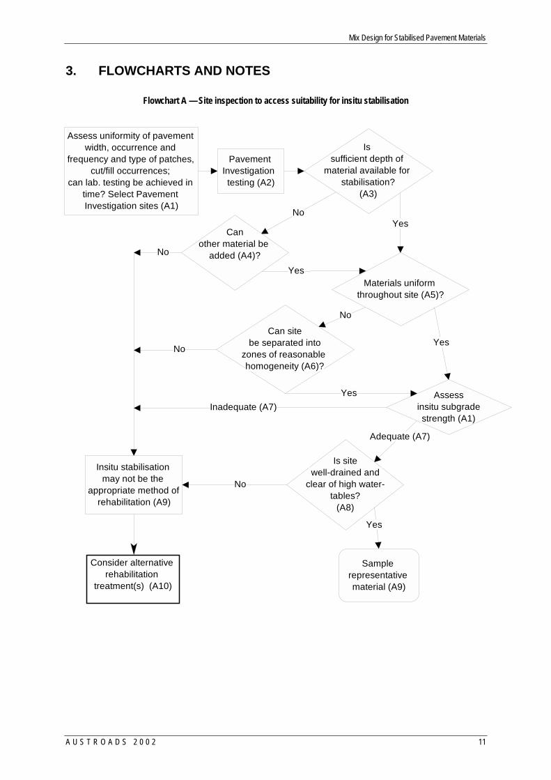
Flowchart A — Site inspection to access suitability for insitu stabilisation
Materials uniform throughout site (A5)?
Is sufficient depth of
material available for stabilisation?
(A3)
YesNo
Can other material be
added (A4)?No
Insitu stabilisation may not be the
appropriate method of rehabilitation (A9)
Yes
No
Can site be separated into
zones of reasonable homogeneity (A6)?
No
Yes
Yes Assess insitu subgrade
strength (A1)Inadequate (A7)
Assess uniformity of pavement width, occurrence and
frequency and type of patches, cut/fill occurrences;
can lab. testing be achieved in time? Select Pavement Investigation sites (A1)
Adequate (A7)
Pavement Investigation testing (A2)
Sample representative material (A9)
Is site well-drained and
clear of high water- tables?
(A8)
No
Yes
Consider alternative rehabilitation
treatment(s) (A10)
Mix Design for Stabilised Pavement Materials
12 A U S T R O A D S 2 0 0 2
Notes for Site Inspection Flowchart (A)
A1 Screen pavement to select pavement investigation sites for deflectograph/FWD testing based on historical data and if available ground-penetrating radar.
Excessive patching may require the material to be milled and graded to assist with making the existing pavement material more homogeneous.
A2 Select sufficient material from the road to carry out the test program and as reserves for differences in construction. The grading curve, PI, insitu CBR are important elements in the pavement investigation program, and further details are noted in Appendix B.
Also, the designer may inquire if it is possible that the material can be subjected to pulverisation from a reclaimer/stabiliser with significant breakdown.
A3 Some existing roads have been constructed with a lower quality subbase material and this underlying granular material may be suitable for stabilisation.
A4 Consider changes to existing pavement geometry, vertical and horizontal alignment and pavement materials' availability. Verify combined grading curve is still suitable for stabilisation (refer to Section 2.6).
Incorporating plastic subgrade material into the mixing process may reduce pavement stiffness, and some consideration may be given to importing material.
A5 PI, gradings, moisture content and physical appearance are similar.
A6 Homogeneity to include: material type, layer thickness and subgrade strength.
A7 Refer to Section 2.7 on minimum subgrade strength and methods to improve subgrade strength.
A8 Can subsurface drains be installed? (Materials in floodways would be an exception to this consideration.)
A9 Consider the availability of laboratory resources and project budget.
A10 Consider other design options, such as raising the road alignment.
Mix Design for Stabilised Pavement Materials
A U S T R O A D S 2 0 0 2 13
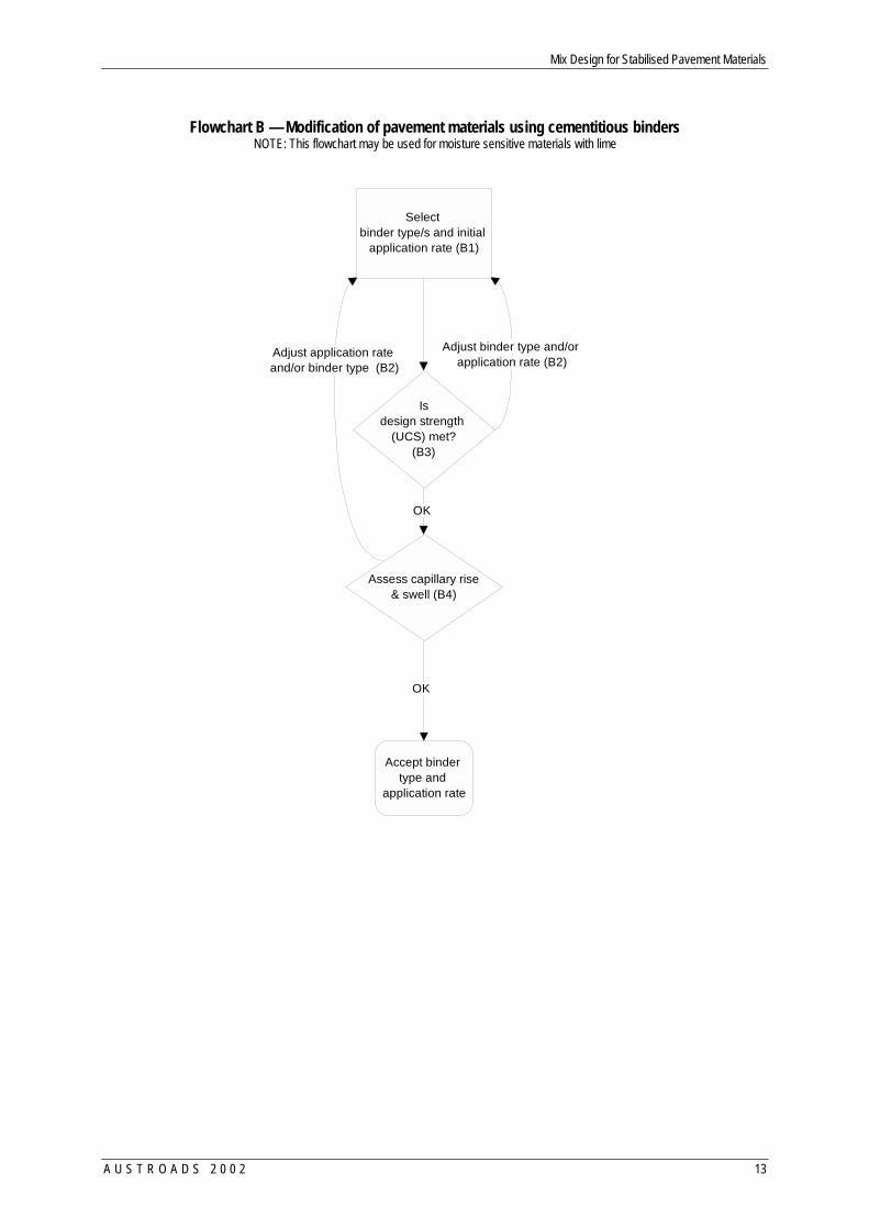
Flowchart B — Modification of pavement materials using cementitious binders
NOTE: This flowchart may be used for moisture sensitive materials with lime
Assess capillary rise & swell (B4)
OK
Accept binder type and
application rate
Adjust binder type and/or application rate (B2)
Select binder type/s and initial
application rate (B1)
Is design strength
(UCS) met? (B3)
Adjust application rate and/or binder type (B2)
OK
Mix Design for Stabilised Pavement Materials
14 A U S T R O A D S 2 0 0 2
Notes on Modification of Pavement Materials using Cementitious Binders. Flowchart B.
B1 Refer to Table 2 for initial binder selection. In some cases the parent insitu pavement material may need an improvement in grading, and any additional material needs to be included in the laboratory sample. The designer and/or the laboratory staff may also give consideration to testing two or more binders and sufficient materials need to be acquired from the site.
B2 Should the desired strength from a specific binder not meet the minimum UCS criteria, increase binder content initially. Should the application rate be higher than 5%, it is suggested that an alternative binder be considered. When lime as a binder is used for controlling moisture sensitivity, strength testing may not be appropriate.
B3 Use AS1141.51 for 28-day strength values with standard compaction and moist cured in accordance with Clause 8(a), unless otherwise specified. Accelerated testing at 7-days may be carried out on a relative basis for establishing initial binder type and content (refer to Appendix E).
B4 Capillary rise and swell assessment to be carried out to AS1141.53 (refer to Section 2.10). This test is recommended.
Mix Design for Stabilised Pavement Materials
A U S T R O A D S 2 0 0 2 15
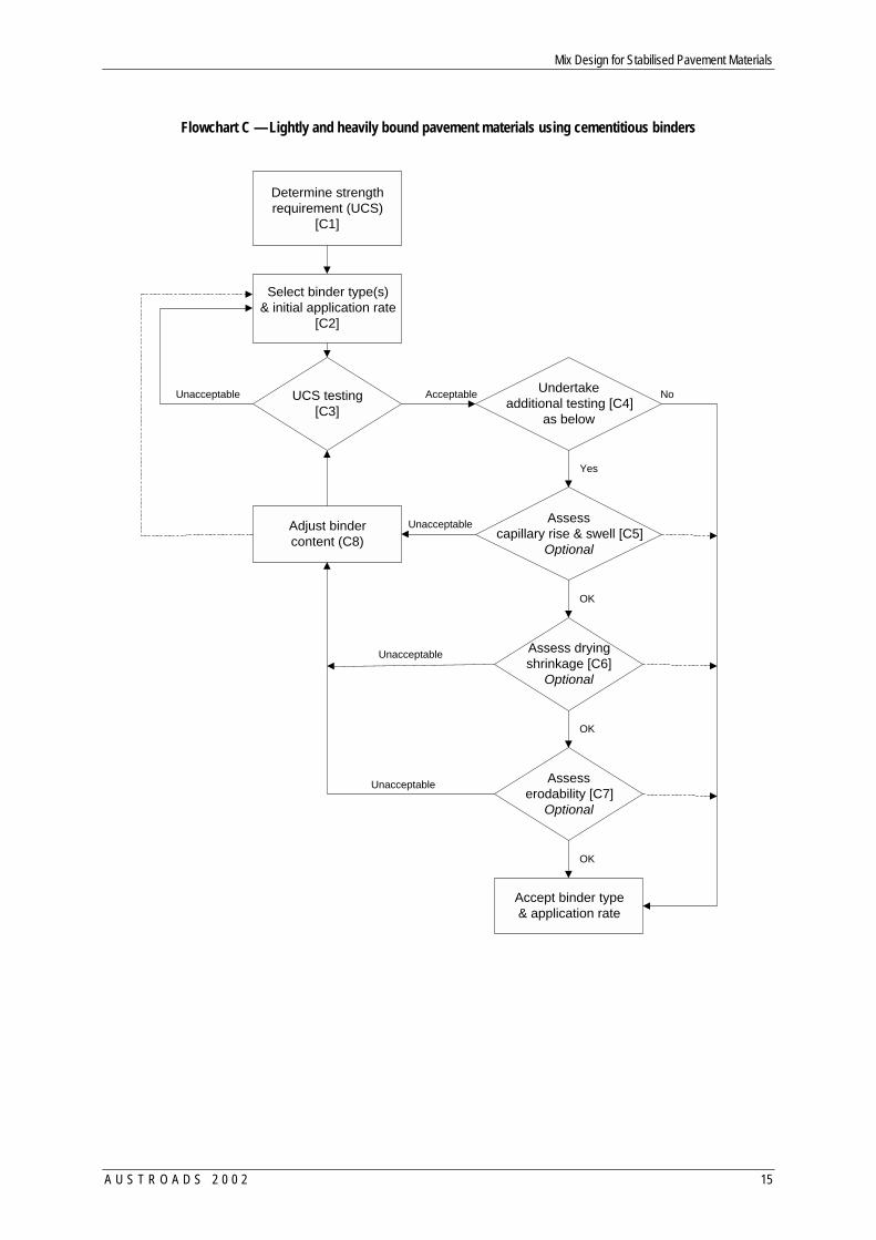
Flowchart C — Lightly and heavily bound pavement materials using cementitious binders
Determine strengthrequirement (UCS)
[C1]
Select binder type(s)& initial application rate
[C2]
UCS testing[C3]
Undertakeadditional testing [C4]
as below
Assesscapillary rise & swell [C5]
Optional
Assess dryingshrinkage [C6]
Optional
Assesserodability [C7]
Optional
Adjust bindercontent (C8)
Accept binder type& application rate
AcceptableUnacceptable
Unacceptable
Unacceptable
Unacceptable
OK
OK
OK
Yes
No
Mix Design for Stabilised Pavement Materials
16 A U S T R O A D S 2 0 0 2
Notes for Lightly/Heavily Bound Pavement Materials using Cementitious Binders Flowchart C.
C1 For appropriate UCS design values for Victoria, Queensland, NSW and South Australia for lightly and heavily bound stabilised pavement materials, refer to Appendix B.
C2 Refer to Tables 2 and 3 for initial binder selection. In some cases the parent insitu pavement material may need an improvement in grading, and any additional material needs to be included in the laboratory samples and test program.
C3 Use AS 1141.51 for the determination of the UCS using standard compaction and either standard or accelerated curing. May consider and compare rate of strength gain between 7 and 28 days under standard curing.
C4 Where a new material is proposed for use without any previous knowledge of its performance in the proposed environment, then additional testing (ie capillary rise, shrinkage, erodability) may be required to reduce the likelihood of moisture sensitivity, unacceptable cracking and erodability.
C5 Capillary rise and swell assessment to be carried out to AS1141.53 (refer to Section 2.10). C6 Refer to Appendix C for notes for drying shrinkage. As a rough indication use the linear
shrinkage test (Standards Australia 1995) to discriminate between binder(s)/content(s). Some road authorities will use an equivalent density obtained using Modified compactive effort.
C7 Consider erodibility testing performed on a sample at 3% lower density as erodibility is sensitive to the degree of compaction. May not undertake this test for lightly bound materials. Also refer to section 2.11 on erodibility.
C8 If there is no improvement in the stabilised material after increasing the binder content, it is suggested that another binder type is selected. For heavily bound materials usually no further UCS testing is required. However, for lightly bound materials, the UCS test should be carried out again to ensure strength limits are met.
In some cases the selected binder may not meet the capillary rise and the other optional tests but meet the UCS requirements and therefore, engineering judgement may override the results from these tests to use the specific binder and content.
Mix Design for Stabilised Pavement Materials
A U S T R O A D S 2 0 0 2 17
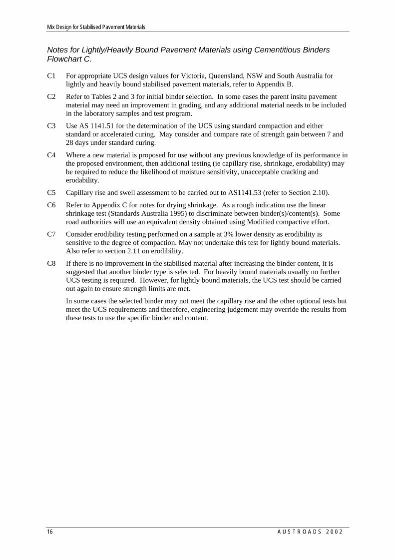
Flowchart D — Subgrade stabilisation using lime.
The binder content may be determined by the UCS (left side flowchart) or CBR approach
Assess Plasticity (D1)
Assess Lime Demand (L d)Minimum % of limefor pH > 12.4 (D2)
Determine minimum % oflime for 1 < UCS < 1.5 MPaat 28 days moist cure (D3)
Assess capillary rise &swell (D4)
Assess erodibilityOptional (D5)
Accept binderapplication rate
Access plasticity & moisturecontent (D1)
Lime demand test (D2)
CBR test (7 days)(D6)
CBR >= 60%
Yes
UCS test @ 28 days (D7)
Access capillary rise & swell(D4)
Mix Design for Stabilised Pavement Materials
18 A U S T R O A D S 2 0 0 2
Notes for Stabilisation using Lime. Flowchart D.
D1 No limit is specified on PI. However, it may not be cost effective to stabilise a highly-plastic clay (i.e. about PI > 40). An initial assessment is still suggested using the Lime Demand test.
D2 The Lime Demand identifies the quantity of lime (Ld) to satisfy cation exchange and short-term reactions. Some soils may not gain strength due to a dominant ion exchange process in the pavement material.
Typically the laboratory will test using hydrated lime and contractors will use quicklime, and therefore, the application rate of quicklime needs conversion from the hydrated lime rate tested (refer to Section 2.5).
Refer to Main Roads Test Method Q133 Lime Demand Test. Also, refer to Transport technology Testing Protocol for Lime Modification and Lime Stabilisation.
D3 It is suggested that the lime content for testing should be at say Ld + 2% and Ld + 4%. Further refinement is usually carried out after these results are obtained.
D4 Capillary rise limit discussed in Section 2.10. Moisture content needs to dry back to below 'optimum' for material to gain strength.
D5 If using lime in area subject to poor drainage/high water tables; will need to ensure erosion resistance, i.e. provide a bound material.
D6 Conduct soaked CBR test after 7 days normal curing. Should the CBR be less than 60% the pavement is likely to behave as an unbound material. For a CBR ≥ 60% it is suggested further tests are conducted to establish the UCS of the stabilised pavement material.
It is common practice to carry out a CBR test on the parent material, and compare this result with the CBR value after stabilisation. If there is no increase in CBR strength, the designer should re-evaluate the use of lime for this subgrade material.
D7 Carry out 28 UCS strength testing to AS 1141.51 using standard compaction energy and curing. Some regions use 7-day accelerated curing techniques. As a rule of thumb the 7-day UCS values represent one-half of the 28-day strength. For UCS greater than about 1 MPa, the material may be bound and similarly behave as a cement-bound layer and fail due to fatigue cracking.
Mix Design for Stabilised Pavement Materials
A U S T R O A D S 2 0 0 2 19
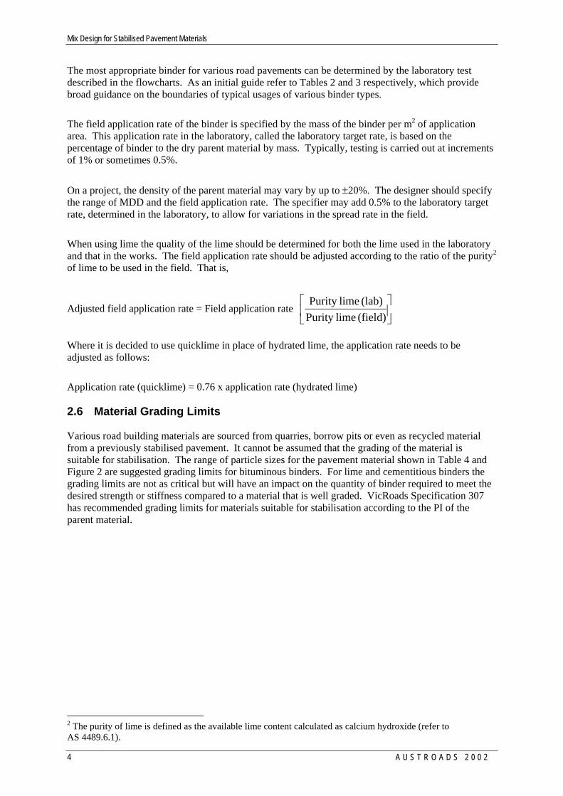
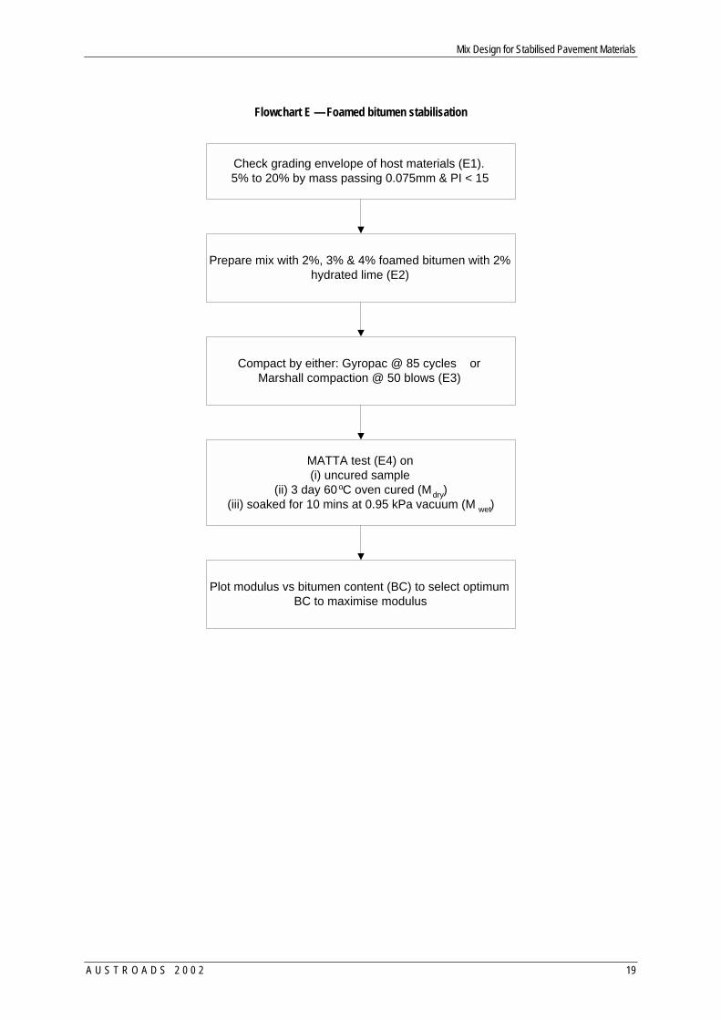
Flowchart E — Foamed bitumen stabilisation
Check grading envelope of host materials (E1).5% to 20% by mass passing 0.075mm & PI < 15
Prepare mix with 2%, 3% & 4% foamed bitumen with 2%hydrated lime (E2)
Compact by either: Gyropac @ 85 cycles orMarshall compaction @ 50 blows (E3)
MATTA test (E4) on(i) uncured sample
(ii) 3 day 60oC oven cured (Mdry)(iii) soaked for 10 mins at 0.95 kPa vacuum (M wet)
Plot modulus vs bitumen content (BC) to select optimumBC to maximise modulus
Mix Design for Stabilised Pavement Materials
20 A U S T R O A D S 2 0 0 2
Notes for Foamed Bitumen Stabilisation. Flowchart E
E1 Refer to Section 2.6 regarding suitable grading curve and PI for insitu material. Additional imported material will assist in reducing PI or adjusting grading curve.
E2 For the selection of bitumen for foaming the expansion ratio should not be less than 10 times and have a half-life period greater than 30 seconds. The 2% requirement for lime is a practical limit in the field. For lightly trafficked roads no lime may be required if the PI of the material is very low. The requirement for no lime should be verified in the laboratory and no guidance is given.
E3 The current two approaches samples are compacted using a Gyropac for 85 cycles or Marshall compaction at 50 blows. There are two approaches to the preparation of the sample and the Gyropac approach is a refinement of the work done by Maccarrone (1994). Work by Jason et al (2000) shows that the pavement material may be sensitive to the type of compaction.
The moisture content of the parent material for sample preparation is typically lower than OMC and the current recommendation is for the moisture content of the parent material prior to mixing be in the range of 70% to 90% of OMC.
Where over sized particles (ie retained in 19.5 mm sieve) are found in the sample it is recommended that a 150 mm diameter mould be used. No guidance is given at this time on how to use the results from a larger sample size.
E4 MATTA6 testing [Ref.5] is carried out on three samples and taking the average results. The MATTA test is an indirect tensile test procedure and it does provide a correlation to the resilient modulus of the sample material.
The samples are oven cured at 60°C for 3 days and tested Mdry. After the samples are tested they are then soaked in water prior to testing to give Mwet. Two methods may be used for soaking the sample, that is submerged under water for 24 hours or in a vacuum chamber for 10 minutes.
The set that is uncured and tested within 1 hour after compaction using the MATTA should have a modulus exceeding 700 MPa for main roads and 500 MPa for light traffic to ensure the pavement can be open to traffic after trimming.
E5 [Mwet / Mdry ] >= 0.5
Bituminous binders will not cure at excessive moisture contents as moisture content needs to dry back to below 'optimum' for material to gain strength; particularly for 'cut-back' and emulsified bitumen.
6 MATTA – Materials Testing Apparatus
Mix Design for Stabilised Pavement Materials
A U S T R O A D S 2 0 0 2 21
4. REFERENCES
Austroads (1998). Guide to Stabilisation in Roadworks. Austroads, Sydney.
Austroads (1998a). A guide to the design of new pavements for light traffic. APRG Report No. 21. Austroads, Sydney.
Austroads (2000). Determination of Unconfined Compressive Strength of Road Materials Stabilised or Modified with Proportions of Cement, Lime or Other Cementitious Materials. Draft A 10th February 2000. Austroads, Sydney.
AustStab and ARRB Transport Research (1999). Selection of Stabilisation Methods for Roadworks. Course notes for Australia: 8 June to 10 August 1999. ARRB Transport Research, Vermont South.
Foley, G.D. (2000). Effect of Design, Construction and Environmental Factors for Long-Term Performance of Stabilised Materials. Contract Report for Austroads. May 2000 RC91022-1. ARRB Transport Research, Vermont South.
Jones, J, Nataatmadja, A and Ramanujam, J Characterisation of foamed bitumen mixes REAAA Conference, Japan , September, 2000
Little, D.N, Scullion, T., Kota, P.BV.S. and Bhuiyan, J. (1995). Guidelines for Mixture Design and Thickness Design for Stabilised Bases and Subgrades. Research Report 1287-3F Texas Transportation Institute, College Station, Texas, Report, No. TX-95/1287-3F, Texas. Department of Transportation, Austin, Texas.
Maccarrone, S, Holleran, G, Leonard, DJ and Hey, S Pavement recycling using foamed bitumen Proceedings 17th ARRB Conference, Part 3, Gold Coast, August, 1994.
Queensland Transport (1990). Pavement Design Manual. Second Edition 1990. Queensland Dept. of Transport, Brisbane.
Rawlings, R.E., Williams, D.J. and Gordon, R.G. (1988). Laboratory and field comparisons of cement treated paving materials. In Proc. of 14th Australian Road Research Board (ARRB) Conference, 1988, Canberra. Vol. 14, No. 7, ARRB, Vermont South.
Roads and Traffic Authority, RTA (1993). Proceedings of the Workshop on Deep-Lift Recycling of Granular Pavements. Roads and Traffic Authority (RTA) NSW, Cement & Concrete Association of Australia. Sydney, Dec. 1993. RTA, Roseberry.
RTA (1994). Determination of the Erodability of Stabilised Materials. Test Method T186 Draft. Roads and Traffic Authority, Sydney.
RTA (199X). Determination of Unconfined Compressive Strength of Road Materials Stabilised or Modified with Proportions of Cement. Test Method T131. Roads and Traffic Authority, Sydney.
Sherwood, P. (1993). Soil Stabilisation with Cement and Lime. TRL State of the Art Review. Transport Research Laboratory. HMSO. London.
Smith, G. and Caltabiano. M. (1987). The Use of Low Shrinkage CTB in District 14 (Metropolitan South). Paper presented to Main Roads Dept. Metropolitan Divisional Technical Symposium (Brisbane: Main Roads Department Queensland).
Smith, R.B. and Hawkins, G. (1982). Utilisation of calcretes for road pavement construction in the arid Western Area of New South Wales. In Proc. Of 11th Australian Road Research Board (ARRB) Conference 1982, Melbourne. Vol. 11, No. 3, Australian Road Research Board, Vermont South.
Standards Australia (1987). Methods of testing soils for engineering purposes - Soil strength and consolidation tests - Determination of the penetration resistance of a soil - 9kg dynamic cone penetrometer test. AS 1289.6.3.2-1997. Standards Australia, Strathfield, New South Wales

Mix Design for Stabilised Pavement Materials
22 A U S T R O A D S 2 0 0 2
________________ (1984). Methods of testing soils for engineering purposes - Soil strength and consolidation tests - Determination of the static cone penetration resistance of a soil - Field test using a mechanical and electrical cone or friction-cone penetrometer. AS 1289.6.5.1-1999 Standards Australia, Strathfield, New South Wales.
________________ (1995). AS 1289.3.4.1-1995. Methods of testing soils for engineering purposes - Soil classification tests - Determination of the linear shrinkage of a soil - Standard method. Standards Australia, Strathfield, New South Wales.
________________ (1996). Methods for sampling and testing aggregates - Unconfined compressive strength of compacted materials. AS 1141.51-1996. Standards Australia, Strathfield, New South Wales.
________________ (1996). Method for sampling and testing aggregates: method 53: absorption, swell and capillary rise of compacted materials. Australian Standard No. AS 1141.53-1996, Standards Australia, Strathfield, New South Wales.
Symons, M. G. (1999). Shrinkage and Erodibility of Cementitious Bound Soils. Structural Materials and Assemblies Group, University of South Australia for Transport SA, Pavements Program Project 97/PA/003. July 1999. (ISBN 0 86803 634 X).
TSA (1998). MTRD Report 94/MT/89-1 Mechanistic Characterisation of Cementitiously Stabilised Pavement Materials. Transport South Australia, Adelaide.
VicRoads (1999). Standard Specification for Roadworks and Bridgeworks. Section 307 – Insitu stabilisation of pavements with cementitious binders. July 1999 edition. VicRoads, Kew.
VicRoads (2000) Lime stabilised subgrade materials – lime content and assignment of CBR and percent swell Code of Practice RC500.23, VicRoads, Kew.
Wallace, K.B., Hines, N. and Golding, W. (1977). A laboratory study of the infiltration characteristics of coarse grained soils. Road Report No. 14, June 1976. James Cook University of North Queensland, Townsville.
Walter, P. (2000). Personal communication.
Williams, R.I.T. (1986). Cement-Treated Pavements. Materials, Design and Construction. Elsevier Applied Science Publishers, London.
Mix Design for Stabilised Pavement Materials
A U S T R O A D S 2 0 0 2 23
5. BIBLIOGRAPHY of Relevant Australian Standards
AS 1289.6.1.2-1998 Methods of testing soils for engineering purposes - Soil strength and consolidation tests - Determination of the California Bearing Ratio of a soil - Standard laboratory method for an undisturbed specimen
AS 1289.6.1.3-1998 Methods of testing soils for engineering purposes - Soil strength and consolidation tests - Determination of the California Bearing Ratio of a soil - Standard field-in-place method
AS 1141.51-1996 Methods for sampling and testing aggregates - Unconfined compressive strength of compacted materials
AS 1141.51-1996/Amdt 1-1999 Methods for sampling and testing aggregates - Unconfined compressive strength of compacted materials
AS 1141.53-1996 Methods for sampling and testing aggregates - Absorption, swell and capillary rise of compacted materials
AS 1289.7.1.3-1998 Methods of testing soil for engineering purposes - Soil reactivity tests - Determination of the shrinkage index of a soil - Core shrinkage index
AS 1012.13-1992 Methods of testing concrete - Determination of the drying shrinkage of concrete for samples prepared in the field or in the laboratory
AS 1012.13-1992/Amdt 1-1993 Methods of testing concrete - Determination of the drying shrinkage of concrete for samples prepared in the field or in the laboratory.
Mix Design for Stabilised Pavement Materials
24 A U S T R O A D S 2 0 0 2
APPENDIX A — Test methods for subgrade strength The most appropriate methods for determining subgrade strength are field-estimated CBR tests, such as the:
• Dynamic Cone Penetrometer, and
• Static Cone Penetrometer test.
These tests are termed ‘estimated’, as they are a quick and indirect methods of estimating the soil strength from use of previously derived correlations of cone values to strength. The advantage of such testing is the economy and speed of data collection.
Australian Standard AS1289. F3.2 1984 and F5.1 1984 Method 5.1.1 describe the dynamic penetration cone and the static cone penetration test respectively (Standards Australia 1984).
Other methods are available to provide CBR values such as:
• Standard laboratory method (AS1289.F1.2 1977 Method F1.2), and
• Standard field-in-place method (AS1289.F1.3 1977 Method F1.3); not preferred.
These tests, whilst providing an accurate strength determination of the soil are not entirely appropriate if the sample being tested in the laboratory does not replicate the field conditions. This is particularly significant where there may be substantial material variability in terms of composition, density and moisture content. Where no other information is available, the use of a soaked-CBR test may provide an indication of the subgrade’s bearing strength.
The in-place Field CBR test is a slow and hence costly test, which for a non-uniform subgrade material, will potentially describe only the strength of the immediate handful of soil. It would take many tests at many layers and at different locations to derive a characteristic value of subgrade support for the whole site.
Use of a deflectograph, Benkelman Beam or the Falling Weight Deflectometer will assist in gaining an appreciation of variations in subgrade strength given the depth of pavement is reasonable well known. These devices can be used to identify zones of relative pavement weakness, where either remedial works such as drainage improvements etc., or additional material may be required to provide a more uniform strength pavement prior to stabilisation.
The following notes may provide the engineer with a site evaluation plan. ! Identify likely sections that have similar subgrade type and pavement configuration. Subgrade
types can be inferred from adjacent materials in road reserve etc, existing cuts and fills or plans.
! Pavement configuration can be obtained from plans.
! Inspect pavement and identify areas of concern which warrant investigation.
! Formulate an investigation program sampling at least every 250 to 500 m. Decide whether trenches or pits in say the IWP are appropriate based on construction records and observation of pavement conditions.
! Prepare a sampling and field testing brief describing the work required, sample quantities, test site locations and special instructions.
! Excavate at each location sampling and recording layer depths. Note unusual occurrences such as presence of water, material contamination., etc.
Mix Design for Stabilised Pavement Materials
A U S T R O A D S 2 0 0 2 25
! Photograph each material type as well as providing views of the test site before excavation and the excavation itself. It may be necessary to use paint lines to denote layer boundaries.
! Sample pavement for PSD, Atterberg Limits, MC and Unified Classification including material description. Undertake DCP in the subgrade. Sample subgrade for PSD, Atterberg Limits, MC and Unified Classification and possible laboratory CBR.
! It may be necessary to include some additional test holes to better define material boundaries.
! Laboratory testing, classification tests, test hole profiles (showing material descriptions, MC and DCP data) and laboratory CBR's (after grouping like materials based on above data and observations).

Mix Design for Stabilised Pavement Materials
26 A U S T R O A D S 2 0 0 2
APPENDIX B — UCS testing in regional areas
The following appendix lists the minimum USC values for Victoria, NSW, Queensland, Western Australia and South Australia.
VicRoads (1999)
Table 307.052, reproduced below, refers to the cementitious binder content and the UCS of laboratory prepared samples compacted using Modified compactive effort.
Cementitious stabilising agent content (% by mass)
Minimum 7 day UCS at modified compactive effort (MPa)
Type of work
Min Max. GP Cement GB Cement Slag/lime blends Material Modification 2.0 3.0 2 1.5 1 Fully bound (Deep-lift Stabilisation
4.5 5.5 Not applicable
3.5 2.5
Roads and Traffic Authority - NSW
Guide Notes (RTA 1999) suggest that with the minimum addition of 4% by mass of cementitious binder using Standard compactive effort, that the 7 day accelerated cure with 4 hour soak minimum UCS (RTA T131, 2000) value should be greater than 4 MPa.
Main Roads, Queensland
Queensland Transport (1990) describes three categories of cemented granular materials.
Category 1. The stabilised material shall have an UCS of at least 3 MPa when tested in accordance with test procedure Q115 (Unconfined compressive strength, 1978). Q115 uses Standard compactive effort. This material has an assumed modulus of 5000 MPa.
Category 2 The stabilised material shall have an UCS of at least 2 MPa when tested in accordance with test procedure Q115. This material has an assumed modulus of 2000 MPa.
Category 3 This plant-mixed stabilised material shall have an UCS of at least 8 MPa when tested in accordance with test procedure Q115. This material has an assumed modulus of 15,000 MPa.
Transport South Australia
TSA (1998) refers to two categories of cemented granular material:
Bound: A minimum resilient modulus (ER) of 2,000 MPa is used in mechanistic pavement design. Research with South Australian crushed quarry products indicates that a minimum of 3% Type GB cement is required to achieve this stiffness.
Modified: A Resilient Modulus of 1,000 MPa is targeted to ensure minimal tensile strength. 1% Type GB cement in crushed quarry material may achieve this stiffness under laboratory conditions.
Mix Design for Stabilised Pavement Materials
A U S T R O A D S 2 0 0 2 27
TSA (1998) developed the following relationships between resilient modulus (ER ) and UCS at 28 days of:
.........................3001245 cementGBTypeforxUCSER +=
3:1../lim......................222696 2 flyasheforxUCSxUCSER −=
or
1:1../lim......................564574 2 flyasheforxUCSxUCSER +=
Test Method
Australian Standard AS 1141.51-1996 describes the unconfined compressive strength test for compacted materials (Standards Australia 1996). This Standard allows for various testing options to be undertaken, e.g. compactive effort applied to sample etc.. It is recommended that all testing using cementitious binders for UCS assessment be carried out for standard compaction. The designer still has an option to set limits in the field based on either standard or modified compaction levels. RTA NSW
Guide Notes (RTA 1999) suggest that with the minimum addition of 4% by mass of cementitious binder using Standard compactive effort, that the 7 day accelerated cure with 4 hour soak minimum UCS (RTA T131, 2000) value should be greater than 4 MPa.
Main Roads, WA
Cement addition by Main Roads WA is confined to modification rather than stabilisation resulting in a bound material. The target 28 day cure UCS for type LH cement is 0.8 - 1.0 MPa. UCS testing is conducted in general accordance with AS 1141.51.
Cement addition is typically 1.5% - 3.0%. Additive contents as low as 0.75% are necessary with some material, primarily to reduce moisture sensitivity without producing a bound layer. Addition of 0.75% cement is the minimum practical additive content for low plasticity granular materials.
Mix Design for Stabilised Pavement Materials
28 A U S T R O A D S 2 0 0 2
APPENDIX C — Drying shrinkage The magnitude and rate of drying shrinkage is affected by several factors including cement content, moulding moisture content, cement/ additive type, paving material characteristics and curing conditions. To ensure satisfactory pavement performance, it is desirable to identify the relative influence of these factors on drying shrinkage.
Studies show that drying shrinkage:
• Increases with increased plasticity and increased plastic-fines content. • Is highly dependent upon the clay mineralogy. • Generally decreases with increasing ‘cement’ content for a plastic soil. • Initially may decrease to the optimum cement content, then generally increases with continued
increasing ‘cement’ content for non-cohesive soils such as granular base materials. • Decreases with decreasing density. • May be indicated by measurement of the linear shrinkage (LS) of the raw material. • The use of low cement contents with highly plastic granular materials can result in substantial
drying shrinkage. • Varies with each binder type and host material combination.
The practical measures to reduce drying shrinkage are:
• Use material with less reactive clay minerals. • Use lower PI materials (desirable to limit to <4); • Use material with low LS (desirable to limit to <1.5%) • Reduce the fines content; if possible to <10% by mass (finer than 75µm) • Use specialised plant/equipment and use two-pass mixing. • Compact slightly dry of optimum moisture content. • Use of water reducing agents during construction. • Use of slower-setting blended or supplementary cementitious materials. The drying shrinkage ranges and suggested limits are:
• A suggested limit to produce low-shrinkage cement-treated basecourse material is 200 µm at 7 days cure (Smith and Caltabiano 1987). This limit would be considered too onerous for deep-lift insitu stabilisation where material variability and quality would be less than that of a base material for CTB production.
• Work reported by Rawlings, Williams and Gordon (1988) reports long-term (56+ days) drying shrinkages for host materials of PI >4 of between 300 to 600 µm.
• A major study undertaken by Symons (1999) on three quarry rubbles (PI vales of 0, 1 and 7; LS values of 0%, 2% and 1.5% respectively; % finer than 75 µm 1%, 10% and 2% respectively) with 4% cementitious binder at OMC at 98% DR at 56 days ranged from 600 to 1100 µm. Non-dosed quarry rubbles at the same moulding, curing and measurement parameters recorded drying shrinkages of between 2000 and 4500 µm, thus at this treatment, the addition of binder has produced a substantial reduction in the drying shrinkage.
Mix Design for Stabilised Pavement Materials
A U S T R O A D S 2 0 0 2 29
The following notes suggest a procedure for drying shrinkage (from Rawlings, Williams and Gordon 1988). The steps involved in the determination of the drying shrinkage of a cement-treated material are as follows:
(a) Determination of the liquid limit (LL), the plastic limit (PL), the plasticity index (PI), the linear shrinkage (LS), and the particle size distribution (grading) of the untreated soil.
(b) For the chosen cement/additive type and content, determination of the laboratory maximum dry density (standard compaction), γd/std and the laboratory standard optimum moisture content, wo/std.
(c) Preparation of drying shrinkage specimens (100 mm by 100 mm by 350 mm long) in triplicate and curing for 18 hours in environmental conditions of 26°C and 90% relative humidity prior to demoulding.
(d) Demoulding and attaching brass gauge studs to the centre of each of the specimens using epoxy resin and curing for a further six hours at 26°C and 90% relative humidity.
(e) Measurement of the initial lengths of the specimens, lo (mm) using the horizontal length comparator.
(f) Measurement of the lengths of the specimens, li (mm) at gradually increasing intervals up to 90 days; the specimens being kept in a controlled environment of 26°C and 90% relative humidity.
(g) Determine the drying shrinkage at 90 days, (µτ) for each specimen by
Ed/90d = (1o – li) x 106/1o
The test method has been modelled to a large degree on AS1012, Part 13-1970 Method for the Determination of Drying Shrinkage of Concrete. The concepts of a horizontal length comparator, reference bar, drying room and gauge studs are common to both test methods. Even the specimen dimensions are similar (75 mm by 75 mm by 285 mm long concrete specimens compared to 100 mm by 100 mm by 350 mm long cement-treated material specimens).
Mix Design for Stabilised Pavement Materials
30 A U S T R O A D S 2 0 0 2
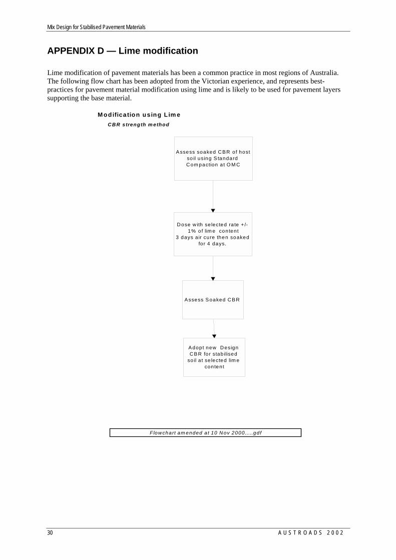
APPENDIX D — Lime modification Lime modification of pavement materials has been a common practice in most regions of Australia. The following flow chart has been adopted from the Victorian experience, and represents best-practices for pavement material modification using lime and is likely to be used for pavement layers supporting the base material.
M odification using L im e
A ssess soaked C B R o f host so il using S tandard C om paction a t O M C
D ose w ith se lected ra te + /- 1% o f lim e con tent
3 days a ir cure then soaked for 4 days.
A ssess S oaked C B R
A dopt new D esign C B R fo r stab ilised
so il a t se lected lim e content
C B R strength m ethod
Flow chart am ended a t 10 N ov 2000.....gd f
Mix Design for Stabilised Pavement Materials
A U S T R O A D S 2 0 0 2 31
APPENDIX E — Accelerated curing of samples stabilised with cementitious binders
Accelerated curing of samples may be necessary to reduce the time taken to evaluate a range of binders and application rates. The following procedure for oven dried accelerated curing has been adopted from RTA Test method T131. The apparatus required is a thermostatically controlled oven with good air circulation, which can be maintained at 65°C ± 5°C.
The curing of samples is important as strength development will be a function of the moisture content and temperature during the curing stage and before testing. Where the specifier changes from the following procedure, the curing procedure should be reported.
(a) Wrap each test specimen in a protective cover such as wet newspaper and seal (e.g. in foil and/or an oven bag) to ensure that the specimens do not dry out.
(b) For accelerated curing store the cylinders in an oven capable of maintaining a temperature range of 65°C ± 5°C for the specified period.
(c) Specimens should be cured for seven days unless otherwise specified.
(d) Remove the specimens from their curing environment and remove coverings of newspaper etc.
(e) Inspect each cylinder and record whether or not it has dried out during curing.
(f) If so specified, break up the cylinder and immediately recompact all of the material.
(g) Immerse each test cylinder in water at room temperature. The specimen should be covered by approximately 10 mm of water so that the entrapped air may escape.
(h) Remove from the bath after a minimum of four hours up to a maximum of four and a half-hours. Drain for approximately 15 minutes.
INFORMATION RETRIEVAL
Austroads (2002), Mix Design For Stabilised Pavement Materials, Sydney, A4, 43pp, AP-T16/02
KEYWORDS: Bitumen, Cement, Characterisation, laboratory testing, lime, stabilised materials ABSTRACT: This report provides mix design flow charts for stabilised materials using lime, cementitious and bituminous binders. The mix design is based on laboratory characterisation using state-of-the-art approaches used by State Road Authorities, local government engineers and consultants. These flowcharts may be used for subgrade, subbase and base pavement material layers.

AUSTROADS PUBLICATIONS Austroads publishes a large number of guides and reports. Some of its publications are: AP-1/89 Rural Road Design AP-8/87 Visual Assessment of Pavement Condition Guide to Traffic Engineering Practice
AP-11.1/88 Traffic Flow AP-11.9/88 Arterial Road Traffic Management AP-11.2/88 Roadway Capacity AP-11.10/88 Local Area Traffic Management AP-11.3/88 Traffic Studies AP-11.11/88 Parking AP-11.4/88 Road Crashes AP-11.12/88 Roadway Lighting AP-11.5/88 Intersections at Grade AP-11.13/95 Pedestrians AP-11.6/93 Roundabouts AP-11.14/99 Bicycles AP-11.7/88 Traffic Signals AP-11.15/99 Motorcycle Safety AP-11.8/88 Traffic Control Devices
AP-12/91 Road Maintenance Practice AP-13/91 Bridge Management Practice AP-14/91 Guide to Bridge Construction Practice AP-15/96 Australian Bridge Design Code AP-17/92 Pavement Design AP-18/00 RoadFacts 2000 AP-22/95 Strategy for Pavement Research and Development AP-23/94 Waterway Design, A Guide to the Hydraulic Design of Bridges, Culverts & Floodways AP-26/94 Strategy for Structures Research and Development AP-C29/01 Austroads Strategic Plan 2001–2004 AP-G30/02 Road Safety Audit – 2nd Edition AP-34/95 Design Vehicles and Turning Path Templates AP-36/95 Adaptions and Innovations in Road & Pavement Engineering AP-38/95 Guide to Field Surveillance of Quality Assurance Contracts AP-40/95 Strategy for Ecological Sustainable Development AP-41/96 Bitumen Sealing Safety Guide AP-42/96 Benefit Cost Analysis Manual AP-43/00 National Performance Indicators AP-44/97 Asphalt Recycling Guide AP-45/96 Strategy for Productivity Improvements for the Road Transport Industry AP-46/97 Strategy for Concrete Research and Development AP-47/97 Strategy for Road User Costs AP-48/97 Australia at the Crossroads, Roads in the Community — A Summary AP-49/97 Roads in the Community — Part 1: Are they doing their job? AP-50/97 Roads in the Community — Part 2: Towards better practice AP-51/98 Electronic Toll Collection Standards Study AP-52/97 Strategy for Traffic Management Research and Development AP-53/97 Strategy for Improving Asset Management Practice AP-54/97 Austroads 1997 Bridge Conference Proceedings — Bridging the Millennia AP-55/98 Principles for Strategic Planning AP-56/98 Assessing Fitness to Drive AP-57 & 58/98 Cities for Tomorrow — Better Practice Guide & Resource Document AP-59/98 Cities for Tomorrow — CD AP-60/98 Guide to Stabilisation in Roadworks AP-61/99 Australia Cycling 1999-2004 — The National Strategy AP-62/99 e-transport — The National Strategy for Intelligent Transport Systems AP-63/00 Guide to the Selection of Road Surfacings AP-64/00 Austroads 4th Bridge Conference Proceedings — Bridges for the New Millenium AP-G65.1/01 Road Condition Monitoring Guidelines: Part 1 – Pavement Roughness AP-G66/02 Asphalt Guide AP-G67/02 Travel Demand Management: A Resource Book AP-G68/01 Guide to Heritage Bridge Management AP-G69/02 Urban Road Design: A Guide to the Design of Major Urban Roads These and other Austroads publications may be obtained from: ARRB Transport Research Ltd Telephone: +61 3 9881 1547 500 Burwood Highway Fax: +61 3 9887 8144 VERMONT SOUTH VIC 3131 Email: [email protected] Australia Website: www.arrb.com.au or from road authorities, or their agent in all States and Territories; Standards New Zealand; Standards Australia & Bicycle New South Wales.