australian hydrological geospatial fabric (geofabric ... · australian hydrological geospatial...
TRANSCRIPT

Australian Hydrological Geospatial Fabric (Geofabric)
Product Guide
Geofabric Surface CartographyGeofabric Surface NetworkGeofabric Surface CatchmentsGeofabric Groundwater CartographyGeofabric Hydrology Reporting CatchmentsGeofabric Hydrology Reporting Regions
Version 2.1 – November 2012

Australian Hydrological Geospatial Fabric (Geofabric) Product Guide
2 November 2012 | Geofabric Version 2.1
Contact details
Geospatial Data Unit Bureau of Meteorology GPO Box 2334 CANBERRA ACT 2601 Email: [email protected]

Australian Hydrological Geospatial Fabric (Geofabric) Product Guide
November 2012 | Geofabric Version 2.1 3
Contents
1 General information ................................................................................................ 8
1.1 Bureau of Meteorology – role in water information ......................................... 8 1.1.1 The Water Act 2007 .......................................................................... 8
1.2 Project partners ........................................................................................... 9 1.3 Licensing and conditions of use..................................................................... 9 1.4 Feedback .................................................................................................. 10 1.5 Release versioning ..................................................................................... 10 1.6 Delivery phases ......................................................................................... 10
2 Geofabric V2.1 release notes ................................................................................. 11
2.1 Introduction .............................................................................................. 11 2.1.1 General information ........................................................................ 11 2.1.2 Geofabric V2.1 upgrade ................................................................... 11
2.2 Upgrades .................................................................................................. 12 2.2.1 Hydrology Reporting Catchments: simplification of the node-link network
..................................................................................................... 12 2.2.2 Hydrology Reporting Regions: Topographic Drainage Divisions and River
Regions .......................................................................................... 13 2.2.3 Surface Network: Beta Stream Flow Monitoring Points ....................... 14 2.2.4 Surface Cartography and Surface Network: Water Storages update ..... 15 2.2.5 All products: layer (LYR) files update ................................................ 17 2.2.6 All products: updated existing tutorials and new tutorials ................... 18
3 About Geofabric V2.1 ............................................................................................ 19
3.1 Special features of Geofabric V2.1 ............................................................... 21 3.2 Conceptual model supporting the Geofabric design ....................................... 24
4 Product overview.................................................................................................. 25
4.1 Product components .................................................................................. 25 4.2 Relationships between Geofabric Surface Cartography and Geofabric Surface
Network .................................................................................................... 26 4.3 Spatial feature identifiers (IDs) ................................................................... 27 4.4 Attributes common to all feature classes ...................................................... 28 4.5 Geometric networks ................................................................................... 29 4.6 Relationship classes ................................................................................... 29 4.7 Attribute domains ...................................................................................... 29 4.8 Attribute subtypes ..................................................................................... 30
5 Product descriptions ............................................................................................. 31
5.1 Geofabric Surface Cartography ................................................................... 31 5.1.1 Understanding and using Geofabric Surface Cartography .................... 31 5.1.2 Feature classes, feature types, related tables and key attributes ......... 32
5.2 Geofabric Surface Network ......................................................................... 37 5.2.1 Understanding and using Geofabric Surface Network ......................... 37 5.2.2 Feature classes, feature types, related tables and key attributes ......... 38
5.3 Geofabric Surface Catchments .................................................................... 43 5.3.1 Understanding and using Geofabric Surface Catchments .................... 43
Australian Hydrological Geospatial Fabric (Geofabric) Product Guide
4 November 2012 | Geofabric Version 2.1
5.3.2 Feature classes, feature types, related tables and key attributes ......... 44 5.3.3 Using the base level catchments with extended Pfafstetter attribution . 45 5.3.4 NCBLevel1DrainageDivison and NCBLevel2DrainageBasinGroup .......... 45
5.4 Geofabric Groundwater Cartography ........................................................... 46 5.4.1 Understanding and using Geofabric Groundwater Cartography ............ 46 5.4.2 Feature classes, feature types and key attributes ............................... 47 5.4.3 Description of Geofabric Groundwater Cartography feature classes ..... 54
5.5 Geofabric Hydrology Reporting Catchments ................................................. 57 5.5.1 Understanding and using Geofabric Hydrology Reporting Catchments .. 57 5.5.2 Feature classes, feature types, related tables and key attributes ......... 58 5.5.3 Description of Geofabric Hydrology Reporting Catchments data .......... 60 5.5.4 Contracted nodes and confidence attribution ..................................... 60
5.6 Geofabric Hydrology Reporting Regions ....................................................... 64 5.6.1 Understanding and using Geofabric Hydrology Reporting Regions ....... 64 5.6.2 Feature classes, feature types, related tables and key attributes ......... 65
6 Database schemas by product ............................................................................... 67
7 Data dictionaries .................................................................................................. 68
8 Data Product Specifications (DPS) .......................................................................... 69
References ................................................................................................................ 70
Appendix 1: Data mappings – foundation input data to Geofabric Maintenance Geodatabase71
Appendix 2: Data mappings – Geofabric Maintenance Geodatabase to Geofabric V2.1 product suite .......................................................................................................... 82
Appendix 3: The Pfafstetter reference system and attribute descriptions for the Pfafstetter table ......................................................................................................... 86
Appendix 4: Data quality information for the foundation data inputs ................................. 89
References (Appendices 1 to 4) ..................................................................................... 94
Australian Hydrological Geospatial Fabric (Geofabric) Product Guide
November 2012 | Geofabric Version 2.1 5
List of tables
Table 1 - Geofabric V2.1 upgrades ................................................................................... 11 Table 2 - Geofabric River Region changes from V2.0 to V2.1 .............................................. 14 Table 3 - New Bureau Water Storage attribution ............................................................... 16 Table 4 – Product file sizes and formats ........................................................................... 25 Table 5 – Feature class attributes common to all the Geofabric products ............................. 28 Table 6 – Feature classes and tables for Geofabric Surface Cartography ............................. 32 Table 7 – Bureau generated feature classes (nodes and streams) included for Geofabric
Surface Cartography ....................................................................................... 35 Table 8 – Key attributes of the AHGFMappedNode feature class for Geofabric Surface
Cartography ................................................................................................... 36 Table 9 – Key attributes of the AHGFMappedStream feature class for Geofabric Surface
Cartography ................................................................................................... 36 Table 10 – Key attributes of the AHGFMappedConnectivityDown (downstream) table for
Geofabric Surface Cartography ........................................................................ 36 Table 11 – Key attributes of the AHGFMappedConnectivityUp (upstream) table for Geofabric
Surface Cartography ....................................................................................... 36 Table 12 – Key attributes of the AHGFMappedSegment_FS table for Geofabric Surface
Cartography (flow split table for use with ArcHydro tools) .................................. 36 Table 13 - Feature classes and tables for Geofabric Surface Network .................................. 38 Table 14 – Bureau generated feature classes (nodes and streams) included for Geofabric
Surface Network............................................................................................. 40 Table 15 – Key attributes of the AHGFNetworkNode feature class for Geofabric Surface
Network ........................................................................................................ 41 Table 16 – Key attributes of the AHGFNetworkStream feature class for Geofabric Surface
Network ........................................................................................................ 41 Table 17 – Key attributes of the AHGFNetworkConnectivityDown (downstream) table for
Geofabric Surface Network .............................................................................. 41 Table 18 – Key attributes of the AHGFNetworkConnectivityUp (upstream) table for Geofabric
Surface Network............................................................................................. 41 Table 19 – Key attributes of the AHGFNetworkSegment_FS table for Geofabric Surface
Network (flow split table for use with ArcHydro tools) ....................................... 42 Table 20 – Feature classes and tables for Geofabric Surface Catchments ............................ 44 Table 21 – Key attributes of AHGFCatchment feature class for Geofabric Surface Catchments
.................................................................................................................... 44 Table 22 – Key attributes of NCBLevl1DrainageDivision feature class for Geofabric Surface
Catchments ................................................................................................... 44 Table 23 – Key attributes of NCBLevel2DrainageBasinGroup feature class for Geofabric Surface
Catchments ................................................................................................... 44 Table 24 – Feature classes and tables for Geofabric Groundwater Cartography .................... 47 Table 25 – Key attributes of AHGFAquiferBoundary feature class for Geofabric Groundwater
Cartography ................................................................................................... 47 Table 26 – Key attributes of AHGFAquiferContour feature class for Geofabric Groundwater
Cartography ................................................................................................... 48 Table 27 – Key attributes of AHGFAquiferOutcrop feature class for Geofabric Groundwater
Cartography ................................................................................................... 48

Australian Hydrological Geospatial Fabric (Geofabric) Product Guide
6 November 2012 | Geofabric Version 2.1
Table 28 – Key attributes of AHGFSurficialHydrogeologicUnit feature class for Geofabric Groundwater Cartography ............................................................................... 49
Table 29 – Key attributes of AHGFWaterTableAquifer feature class for Geofabric Groundwater Cartography ................................................................................................... 50
Table 30 – Key attributes of IGWAquiferSalinity feature class for Geofabric Groundwater Cartography ................................................................................................... 51
Table 31 – Key attributes of IGWAquiferYield feature class for Geofabric Groundwater Cartography ................................................................................................... 52
Table 32 – Key attributes of IGWWaterTableHydraulicConductivity feature class for Geofabric Groundwater Cartography ............................................................................... 53
Table 33 – Key attributes of IGWWaterTableSalinity feature class for Geofabric Groundwater Cartography ................................................................................................... 53
Table 34 – Key attributes of IGWWaterTableYield feature class for Geofabric Groundwater Cartography ................................................................................................... 54
Table 35 – Feature classes and tables for Geofabric Hydrology Reporting Catchments .......... 58 Table 36 – Key attributes of AHGFContractedCatchment feature class for Geofabric Hydrology
Reporting Catchments .................................................................................... 59 Table 37 – Key attributes of AHGFLink feature class for Geofabric Hydrology Reporting
Catchments ................................................................................................... 59 Table 38 – Key attributes of AHGFNode feature class for Geofabric Hydrology Reporting
Catchments ................................................................................................... 59 Table 39 – Key attributes of AHGFNodeLinkConnectivityDown table for Geofabric Hydrology
Reporting Catchments .................................................................................... 59 Table 40 – Key attributes of AHGFNodeLinkConnectivityUp table for Geofabric Hydrology
Reporting Catchments .................................................................................... 60 Table 41 – Candidate contracted node creation rules for stream confluences and stream
coastal outlets ................................................................................................ 62 Table 42 – Candidate contracted node creation rules for water bodies and inland sinks ........ 63 Table 43 – Feature classes and tables for Geofabric Hydrology Reporting Regions ............... 65 Table 44 – Key attributes of AWRADrainageDivision feature class for Geofabric Hydrology
Reporting Regions .......................................................................................... 65 Table 45 – Key attributes of RiverRegion feature class for Geofabric Hydrology Reporting
Regions ......................................................................................................... 65 Table 46 – Key attributes of AWRADDContractedCatchmentLookup table for Geofabric
Hydrology Reporting Regions .......................................................................... 65 Table 47 – Key attributes of RRContractedCatchmentLookup table for Geofabric Hydrology
Reporting Regions .......................................................................................... 66 Table 48 – Mapping of AusHydro data to Geofabric Maintenance Geodatabase .................... 72 Table 49 – Mapping of ANUDEM Streams to Geofabric Maintenance Geodatabase ................ 75 Table 50 – Mapping of the National Catchment Boundaries to Geofabric Maintenance
Geodatabase .................................................................................................. 76 Table 51 – Mapping of the OzCoasts to Geofabric Maintenance Geodatabase ...................... 77 Table 52 – Features created by the Bureau to augment the foundation input data in the
Geofabric Maintenance Geodatabase ................................................................ 78 Table 53 – Product feature type registry for Geofabric Surface Cartography ........................ 82 Table 54 – Product feature type registry for Geofabric Surface Network .............................. 83 Table 55 – Product feature type registry for Geofabric Surface Catchments ......................... 84
Australian Hydrological Geospatial Fabric (Geofabric) Product Guide
November 2012 | Geofabric Version 2.1 7
Table 56 – Product feature type registry for Geofabric Groundwater Cartography ................ 84 Table 57 – Product feature type registry for Geofabric Hydrology Reporting Catchments ...... 85 Table 58 – Product feature type registry for Geofabric Hydrology Reporting Regions ............ 85 Table 59 – NCB_Pfafstetter table with field attributes and definitions .................................. 87 Table 60 – Feature classes derived from GEODATA TOPO 250K Series 3 ............................. 93
List of figures
Figure 1 – Geofabric conceptual architecture showing data workflows ................................. 21 Figure 2 – Geofabric V2.1 relationships ............................................................................ 23 Figure 3 – Pfafstetter subdivision of the Fitzroy River basin (Level 1 basin 4) ....................... 87 Figure 4 – Example of tracing the stream network from channel head grid cells to an outlet on
the coast ....................................................................................................... 91
Australian Hydrological Geospatial Fabric (Geofabric) Product Guide
8 November 2012 | Geofabric Version 2.1
1 General information
The intent of this document is to inform the user about the components of the Geofabric V2.1 Products, their foundation data inputs and how they are transformed to create derived data products.
1.1 Bureau of Meteorology – role in water information
The Bureau of Meteorology (the Bureau) is responsible for compiling and delivering comprehensive water information across the water sector. As part of the Water for the Future initiative (see www.environment.gov.au/water/australia/index.html), the Bureau was allocated $450 million by the Australian Government to administer the Improving Water Information Program. This program accurately monitors, assesses and forecasts the availability, condition and use of Australia’s water resources. To achieve this, the Bureau is working with water managers, project partners and stakeholders across Australia to deliver high quality, national water information to government, industry and the community.
The Bureau is building the Australian Water Resources Information System (AWRIS) to provide high quality water information essential to managing Australia’s valuable water resources.
AWRIS will be spatially enabled using the Geofabric, which is a spatial framework for discovering, querying, reporting and modelling water information.
The Geofabric is a specialised set of spatial features within a Geographic Information System (GIS) platform that registers the spatial relationships between important hydrologic features such as rivers, lakes, water storages, aquifers and catchments.
The spatial dimensions of these surface hydrological features and how they are related show how water is stored, transported and used through the landscape.
The vision for the Geofabric is based on similar implementations, such as the National Hydrography Dataset plus (NHDPlus) in the United States (US) which is an integrated suite of application-ready hydrological geospatial data (Horizon Systems 2008). The intention is to use the experience gained in the US and elsewhere, as a benchmark for acquiring related knowledge and therefore improving the Geofabric in Australia.
1.1.1 The Water Act 2007
The Water Act 2007 came into effect on 3 March 2008 and gave the Bureau specific powers and obligations regarding water information in addition to its weather and climate functions under the Meteorology Act 1955.

Australian Hydrological Geospatial Fabric (Geofabric) Product Guide
November 2012 | Geofabric Version 2.1 9
The Bureau’s statutory functions related to water information include:
issuing national water information standards
collecting and publishing water information
conducting regular national water resources assessments
publishing an annual National Water Account
providing regular water availability forecasts
advising on matters relating to water information
enhancing understanding of Australia’s water resources.
1.2 Project partners
The Geofabric is an ongoing project which is the result of considerable effort and consultation by several agencies, both within Australia and internationally. The project is being led by the Bureau in partnership with Geoscience Australia (GA), the Australian National University Fenner School of Environment and Society (ANU) and CSIRO Water for a Healthy Country Flagship (CSIRO).
The partnership provides a collaborative mechanism for obtaining foundation hydrological data, maintaining and upgrading the data and improving the product suite over time. These activities are guided by industry best practice, then tested and made operational through research and development. The Bureau wishes to acknowledge the contributions of agencies in the continuing effort to develop and improve the Geofabric.
1.3 Licensing and conditions of use
Geofabric data supplied in this product are made available under the Creative Commons License conditions (Attribution Australia CC BY), Australia.
For more information on this and other Creative Commons licences visit: creativecommons.org/licenses/by/3.0/au/
Geofabric products should be attributed as follows:
© Commonwealth of Australia (Bureau of Meteorology) 2012
Australian Hydrological Geospatial Fabric (Geofabric) Product Guide
10 November 2012 | Geofabric Version 2.1
1.4 Feedback
The Bureau welcomes feedback on any aspect of this product or its services. Please direct your comments or queries regarding this document or the associated data via:
website feedback form
online survey
email: [email protected]
1.5 Release versioning
Versioning will follow a Version X.Y.Z protocol where X represents a major version release, Y represents a minor version release and Z represents a sub-minor version.
Major version – involves the addition or deletion of new feature classes, changes to data scale or resolution, or updates of a significant nature that require a change to the schema. This excludes maintenance of existing data.
Minor version – involves a minor change to the database that requires a change to the schema, but is minor in nature e.g. an attribute field name correction.
Sub-minor version – involves amendments to existing data (e.g. attribute correction) or the addition of single data entities within existing feature classes and other minor changes. The sub-minor version does not involve a change to the database schema.
1.6 Delivery phases
The Geofabric is a ten-year project that will evolve in phases:
The Geofabric V1.0 release was part of Geofabric Phase 1 and was released on 15 October 2010.
The Geofabric V2.0 release was part of Geofabric Phase 2 and was released on 15 November 2011.
The Geofabric V2.0.1 release was part of Geofabric Phase 2 and was released in December 2011.
This Geofabric V2.1 release is part of Geofabric Phase 2 and was released in September 2012
Subsequent versions, with enhanced data and functionality, will follow in Phase 3.
Australian Hydrological Geospatial Fabric (Geofabric) Product Guide
November 2012 | Geofabric Version 2.1 11
2 Geofabric V2.1 release notes
2.1 Introduction
2.1.1 General information
This section provides release notes for the use and adoption of the Geofabric V2.1 by describing the upgrades and changes that have been made.
2.1.2 Geofabric V2.1 upgrade
Table 1 explains the upgrades that have been implemented in Geofabric V2.1. An explanation of each upgrade is detailed in Section 2.2:
Table 1 - Geofabric V2.1 upgrades
Product Upgrade Hydrology Reporting Catchments
(HR_Catchments)
A simplification of the AHGFNode and AHGFLink
features that give a dendritic representation of the node-link stream network topology.
Hydrology Reporting Regions
(HR_Regions)
Updates to some River Region names and a graphical
representation of the Topographic Drainage Divisions and River Regions.
Surface Network (SH_Network)
The addition of 479 ghost nodes linking stream gauge monitoring points to the AHGFNetworkStream surface
network topology.
Surface Cartography (SH_Cartography)
Surface Network (SH_Network)
An update of the AHGFWaterbody feature class to include references to a number of new Water
Storages as listed at
http://water.bom.gov.au/waterstorage/awris/
All products Updates to the layer files.
All products Updates to existing tutorials and addition of new
tutorials.

Australian Hydrological Geospatial Fabric (Geofabric) Product Guide
12 November 2012 | Geofabric Version 2.1
2.2 Upgrades
2.2.1 Hydrology Reporting Catchments: simplification of the node-link network
The Hydrology Reporting Catchment product includes three feature classes, namely:
AHGFNode: contains contracted nodes that are points of hydrological significance that carry identity. They include the confluence of major named streams, coastal stream termini, waterbody inflow and outflows and inland sinks. It also contains a new class of node called diffuse nodes that represent diffused flow from groups of nodes at coastal, delta or inter-catchment outlets.
AHGFLink: the topological connectors between a subset of contracted nodes that participate in the simplified node-link network.
AHGFContractedCatchment: catchment polygons generated for the subset of contracted nodes that participate in the simplified node-link network. These catchments form the basis of a catchment hierarchy that can be aggregated, based on upstream relationships, to build stable reporting regions.
This product comprises two related views of hydrological features used for analysis and reporting purposes. Firstly, a topological network view of the hydrology represented as a node-link network using a subset of contracted nodes (AHGFNode) and the links (AHGFLink) between them; and secondly, a catchments view of the hydrology using the contracted catchments (AHGFContractedCatchment).
In V2.1, the contracted catchments are based on a subset of the contracted nodes that participate in a simplified node-link network. The full node-link network that was published in V2.0 and V2.01 has been pruned to create a dendritic node-link view of the network by removing bifurcations and ensuring that water flows are uni-directional.
The resulting contracted catchments form a stable, logical, dendritic hierarchy that can be reliably reproduced when moving to a higher resolution or larger scale data. They also provide a stable set of catchments that, among other things, can be aggregated to a number of types of water reporting areas depending on the use case. This contracted catchment hierarchy has been used to create two candidate sets of stable reporting regions given in Hydrology Reporting Regions, namely the Topographic Drainage Divisions and River Regions as discussed in section 2.2.2.
Both this product and the Surface Network product, contain new attribution which identifies diffused contracted nodes, where the flow from groups of nodes (DiffusGrp) at coastal, delta or inter-catchment outlets (DiffusType) are represented by a single strategic contracted node (DiffusKey).

Australian Hydrological Geospatial Fabric (Geofabric) Product Guide
November 2012 | Geofabric Version 2.1 13
2.2.2 Hydrology Reporting Regions: Topographic Drainage Divisions and River Regions
Hydrology Reporting Regions includes two features classes, namely:
AWRADrainageDivision: stable reporting regions at the Drainage Division level.
RiverRegion: stable reporting regions at the River Region level.
Hydrology Reporting Regions is based on aggregations of the contracted catchment hierarchy, discussed in section 2.2.1. The primary use case for the contracted catchment hierarchy is to build stable reporting regions based on user requirements and is the basis for the Topographic Drainage Divisions and River Regions.
The user requirements for the Topographic Drainage Divisions and River Regions were provided by the Water Resources Assessment Section in the Bureau. A set of stable, topographically based reporting areas is required for the Australian Water Resources Assessment. A further requirement was that the reporting areas be based on current research, data and technology with reference to previous work of the Australia Water Resources Management Committee as shown in Australia’s River Basins 1997 (ANZCW0703005427).
The Australian Water Resources Assessment 2010 report adopted the use of the Drainage Divisions (http://www.bom.gov.au/water/awra/2010/index.shtml) and may consider the use of the River Regions in future releases. As the River Regions reporting level is not being used in the current Australian Water Resources Assessment report, the AWRA prefix has been removed from references to River Region.
While the initial requirement for the development of the Topographic Drainage Divisions and River Regions was provided by the Bureau to meet its obligations under the Water Act 2007, these reporting regions are proposed for general adoption wherever stable, topographic based water reporting regions are required. To facilitate the adoption of the Topographic Drainage Divisions and River Regions they can be viewed in a graphical format, providing an easy reference for users
During consultation for developing the Topographic Drainage Divisions and River Regions, some minor amendments were made to the River Region names as shown in Table 2. The Edward River Region boundary was amended and renamed to Billabong-Yanco creeks.
Australian Hydrological Geospatial Fabric (Geofabric) Product Guide
14 November 2012 | Geofabric Version 2.1
Table 2 - Geofabric River Region changes from V2.0 to V2.1
V2.0 River Region name V2.1 River Region name
Avon Avon River–Tyrell Lake
Paroo–Kulkyne Paroo River
Wimmera Wimmera River
Lachlan Lachlan River
Darling Darling River
Goulburn Goulburn River
Upper Murray Upper Murray River
Lower Murray Lower Murray River
Barwon-Condamine–Culgoa Rivers Condamine–Culgoa rivers
Mallee East Upper Mallee
Mallee West Lower Mallee
Edward River Billabong–Yanco creeks
2.2.3 Surface Network: Beta Stream Flow Monitoring Points
Surface Network includes four feature classes, namely:
AHGFWaterbody: a body of fresh water with potential significance for water balance and water reporting purposes.
AHGFNetworkStream: line segments describing where water would flow according to a hydrological enforced 9 second digital elevation model.
AHGFNetworkNode: points located at the end of a network stream segment or at a strategic point along the network.
AHGFCatchment: surface area that drains to a single stream segment.
A selected set of 479 hydrological monitoring points, that have been defined by the Bureau as important reference stations for hydrological prediction and Australian Water Resources Assessment modelling purposes, have been included in the Geofabric.
A semi-automated process has been used to associate the location (spatial co-ordinates) of these reference stations to the AHGFNetworkStream feature that is being measured. This process uses a combination of stream name matching, closest distance and manual verification and results in the creation of an AHGFNetworkNode feature with a subtype classification of NetworkGhostNode.
The representation of each reference station (as a NetworkGhostNode) on a AHGFNetworkStream segment has been verified internally using remote sensing images, topographic data and a review of available jurisdiction monitoring point details. The representations have been checked by Bureau hydrologists.
Creating these NetworkGhostNodes within the AHGFNetworkStream topology allows the creation of monitoring point catchments and reaches for hydrological modelling purposes.
A separate table called BetaSurfaceNetworkMonitoringPoints contains detailed attribution of the monitoring points. This table can be joined to the Surface Network product using
Australian Hydrological Geospatial Fabric (Geofabric) Product Guide
November 2012 | Geofabric Version 2.1 15
the HydroID. For further details, refer to the tutorial ‘Use the Beta Monitoring Point table to extend node attribution’.
2.2.4 Surface Cartography and Surface Network: Water Storages update
Both Surface Cartography and Surface Network share the water body feature class as follows:
AHGFWaterbody: a body of fresh water with potential significance for water balance and water reporting purposes.
A subset of the water bodies within the AHGFWaterBody Feature Class are associated with the Bureau’s Water Storage Product (http://water.bom.gov.au/waterstorage/awris/) and are attributed by SLAKE_Name, SLAKE_Syst and SLAKE_URN. For further information on how to link the Water Storage features in the Geofabric to the Bureau’s Water Storage Website, refer to the tutorial Access Water Storage information.
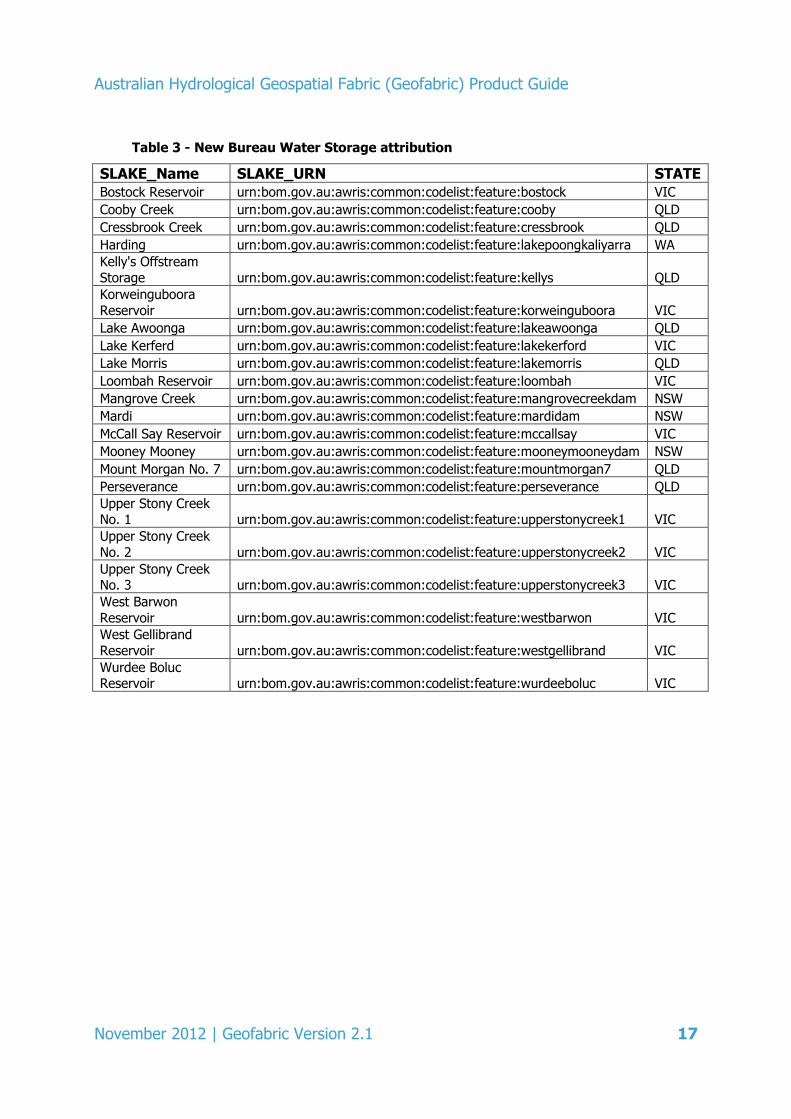
Since the Geofabric V2.0 release in November 2011 a number of new storages have been added to the Water Storages website, 22 of which have been attributed in this Geofabric release as listed in

Australian Hydrological Geospatial Fabric (Geofabric) Product Guide
16 November 2012 | Geofabric Version 2.1
Table 3:
Australian Hydrological Geospatial Fabric (Geofabric) Product Guide
November 2012 | Geofabric Version 2.1 17
Table 3 - New Bureau Water Storage attribution
SLAKE_Name SLAKE_URN STATE
Bostock Reservoir urn:bom.gov.au:awris:common:codelist:feature:bostock VIC
Cooby Creek urn:bom.gov.au:awris:common:codelist:feature:cooby QLD
Cressbrook Creek urn:bom.gov.au:awris:common:codelist:feature:cressbrook QLD
Harding urn:bom.gov.au:awris:common:codelist:feature:lakepoongkaliyarra WA
Kelly's Offstream
Storage urn:bom.gov.au:awris:common:codelist:feature:kellys QLD
Korweinguboora
Reservoir urn:bom.gov.au:awris:common:codelist:feature:korweinguboora VIC
Lake Awoonga urn:bom.gov.au:awris:common:codelist:feature:lakeawoonga QLD
Lake Kerferd urn:bom.gov.au:awris:common:codelist:feature:lakekerford VIC
Lake Morris urn:bom.gov.au:awris:common:codelist:feature:lakemorris QLD
Loombah Reservoir urn:bom.gov.au:awris:common:codelist:feature:loombah VIC
Mangrove Creek urn:bom.gov.au:awris:common:codelist:feature:mangrovecreekdam NSW
Mardi urn:bom.gov.au:awris:common:codelist:feature:mardidam NSW
McCall Say Reservoir urn:bom.gov.au:awris:common:codelist:feature:mccallsay VIC
Mooney Mooney urn:bom.gov.au:awris:common:codelist:feature:mooneymooneydam NSW
Mount Morgan No. 7 urn:bom.gov.au:awris:common:codelist:feature:mountmorgan7 QLD
Perseverance urn:bom.gov.au:awris:common:codelist:feature:perseverance QLD
Upper Stony Creek No. 1 urn:bom.gov.au:awris:common:codelist:feature:upperstonycreek1 VIC
Upper Stony Creek
No. 2 urn:bom.gov.au:awris:common:codelist:feature:upperstonycreek2 VIC
Upper Stony Creek No. 3 urn:bom.gov.au:awris:common:codelist:feature:upperstonycreek3 VIC
West Barwon
Reservoir urn:bom.gov.au:awris:common:codelist:feature:westbarwon VIC
West Gellibrand
Reservoir urn:bom.gov.au:awris:common:codelist:feature:westgellibrand VIC
Wurdee Boluc Reservoir urn:bom.gov.au:awris:common:codelist:feature:wurdeeboluc VIC
Australian Hydrological Geospatial Fabric (Geofabric) Product Guide
18 November 2012 | Geofabric Version 2.1
2.2.5 All products: layer (LYR) files update
Layers are the mechanism used to display geographic datasets in ArcMap. Each layer references a dataset and specifies how that dataset is portrayed using symbols and text labels. When a layer is added to a map, its dataset is specified and its map symbols and labelling properties set.
All layer files associated with the V2.1 release have been updated to enhance user experience. Some of the more notable updates include:
Surface Cartography
Two LYR files, one to show the data structure (polygons, boundaries, nodes) and another without these structures for use when creating maps.
Groundwater Cartography
Symbology based on geological mapping standards used for the IAF_ID attribute for the following Feature Classes:
AHGFSurficialHydrogeologicUnit
AHGFWaterTableAquifer
AHGFAquiferBoundary
AHGFAquiferContour
AHGFAquiferOutcrop
Symbology used for IAF_ID attribute has used the ArcGIS Style Geology 24K. If you experience any problems please turn this Style on.
The geological and aquifer mapping units used in the IAF_ID attribute can be displayed in their correct depth sequence by turning the Symbol Levels on.
The symbology used for the remaining Feature Classes is based on general conventions.
Hydrology Reporting Catchments
Symbology shows the relationship between AHGFNodes and AHGFContractedCatchments.

Australian Hydrological Geospatial Fabric (Geofabric) Product Guide
November 2012 | Geofabric Version 2.1 19
2.2.6 All products: updated existing tutorials and new tutorials
Geofabric tutorials are available to support the use of the Geofabric products. The four existing tutorials have been updated with new titles to make it easier for users to determine their content. Two new tutorials have been added. Included in the tutorials are differences between using ArcGIS V9.3 and ArcGIS V10. The list of tutorials is given below:
Current tutorials
Calculate an upstream drainage area with ArcHydro
Create a subset of Geofabric data
Use the Pfafstetter table to extend catchment attribution
Merge the Geofabric Surface Hydrology products
New tutorials
Access Water Storage information
Calculate rainfall summary statistics for a derived catchment.
Australian Hydrological Geospatial Fabric (Geofabric) Product Guide
20 November 2012 | Geofabric Version 2.1
3 About Geofabric V2.1
The Geofabric is a collection of hydrological geospatial entities (feature classes, tables and raster datasets), representing Australia’s hydrology. Geofabric V2.1 builds new information and functionality into the previously released V2.0 and V2.0.1.
The Geofabric is based on a set of integrated input data products, known as the foundation input data. It builds on these to produce a set of output products based on a defined set of user requirements. These user requirements are focused on the Bureau’s need to meet its statutory requirements for water accounting, assessment and prediction under the Water Act 2007.
The Geofabric is publicly available and can be used as authoritative source data, suitable for a wide range of water information applications.
The foundation input data for Geofabric V2.1 includes:
Topologically connected surface water hydrology, known as AusHydro V1.7.2 (AusHydro) based on GA GEODATA TOPO 250K Series 1 (GEODATA 1) and GEODATA TOPO 250 K Series 3 (GEODATA 3).
Drainage enforced Digital Elevation Model (DEM) based on ANU and GA’s GEODATA 9 Second Digital Elevation Model (DEM-9S) Version 3 (ANU Fenner School of Environment and Society and GA 2008).
Topologically connected flow direction streamlines, known as ANUDEM Streams V1.1.2 (ANUDEM Streams) as developed by ANU using ANUDEM1 that were cross-referenced and additionally informed by AusHydro vector streamlines.
Physically-based stream segment catchments, known as the National Catchment Boundaries V1.1.4 (NCB), derived from the above mentioned ANUDEM Streams and the DEM-9S.
Groundwater boundaries derived from the best available digital groundwater information sourced from Commonwealth, State and Territory jurisdictions as part of the Interim Ground Water Data (IGWD) project.
Data quality information about the foundation data inputs is given in Appendix 4.
From these foundation data, a suite of integrated data products were developed. These are:
Geofabric Surface Cartography Geofabric Surface Hydrology Cartography 1:250,000 scale 2012
SH_Cartography Cartographic representation of hydrological features
1 ANUDEM is a computer program developed by the ANU Fenner School of Environment & Society for
processing data into a digital elevation model.

Australian Hydrological Geospatial Fabric (Geofabric) Product Guide
November 2012 | Geofabric Version 2.1 21
Geofabric Surface Network Geofabric Surface Hydrology Network 1:250,000 scale 2012
SH_Network
Network representation of hydrological features
Geofabric Surface Catchments Geofabric 9 second Catchments 1:250,000 scale 2012
SH_Catchments
Stream segment catchments derived from DEM-9S organised into a hierarchy using the Pfafstetter reference system
Geofabric Groundwater Cartography Geofabric Groundwater Hydrology Cartography 2012
GW_Cartography
Groundwater boundaries derived from the Interim Ground Water Data
Geofabric Hydrology Reporting Catchments Geofabric Hydrology Reporting Catchments 1:250,000 scale 2012
HR_Catchments
Contracted nodes and contracted catchments derived from identification of important hydrological features
Geofabric Hydrology Reporting Regions Geofabric Hydrology Reporting Regions 1:250,000 scale 2012
HR_Regions Topographic Drainage Division and River Region reporting units, based on contracted catchments.
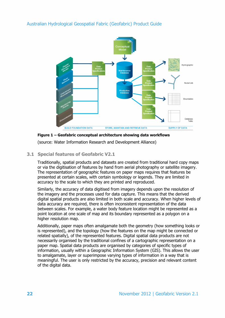
The Geofabric system is based on a conceptual architecture designed to produce a suite of data products at various spatial resolutions, using different representations of features, from a single maintenance environment. This is required to support the disparate needs of users. Key to this design are formal data product specifications that describe each product. Underpinning the Geofabric is a formal, modular conceptual model that allows for direct mapping between the input datasets and products. Figure 1 illustrates the Geofabric conceptual architecture.
Australian Hydrological Geospatial Fabric (Geofabric) Product Guide
22 November 2012 | Geofabric Version 2.1
Figure 1 – Geofabric conceptual architecture showing data workflows
(source: Water Information Research and Development Alliance)
3.1 Special features of Geofabric V2.1
Traditionally, spatial products and datasets are created from traditional hard copy maps or via the digitisation of features by hand from aerial photography or satellite imagery. The representation of geographic features on paper maps requires that features be presented at certain scales, with certain symbology or legends. They are limited in accuracy to the scale to which they are printed and reproduced.
Similarly, the accuracy of data digitised from imagery depends upon the resolution of the imagery and the processes used for data capture. This means that the derived digital spatial products are also limited in both scale and accuracy. When higher levels of data accuracy are required, there is often inconsistent representation of the data between scales. For example, a water body feature location might be represented as a point location at one scale of map and its boundary represented as a polygon on a higher resolution map.
Additionally, paper maps often amalgamate both the geometry (how something looks or is represented), and the topology (how the features on the map might be connected or related spatially), of the represented features. Digital spatial data products are not necessarily organised by the traditional confines of a cartographic representation on a paper map. Spatial data products are organised by categories of specific types of information, usually within a Geographic Information System (GIS). This allows the user to amalgamate, layer or superimpose varying types of information in a way that is meaningful. The user is only restricted by the accuracy, precision and relevant content of the digital data.

Australian Hydrological Geospatial Fabric (Geofabric) Product Guide
November 2012 | Geofabric Version 2.1 23
The design and development of the Geofabric recognises the inherent problems of function, scale and accuracy in representing spatial data. The Geofabric product suite attempts to distinguish between the functional requirements of both topological and geometric representations of hydrological features. Topologically consistent spatial features are those that show connectivity, e.g. consistent direction, node-link connectivity, schematic networks and feature relationships. Geometric spatial features are those that are represented by points, lines or polygons (in ESRI’s ArcGIS environment) and are commonly described as the blue lines for streams and the associated water features (e.g. cartographic representations).
Users can choose the most appropriate Geofabric product to suit their requirements. The user may also select one product to conduct analyses and then adopt the sister product to accomplish an associated task, such as cartographic representation of the same set of features. The value-add of the Geofabric products lies in the ability to reliably apply the products or inter-relate them in a repeatable way.
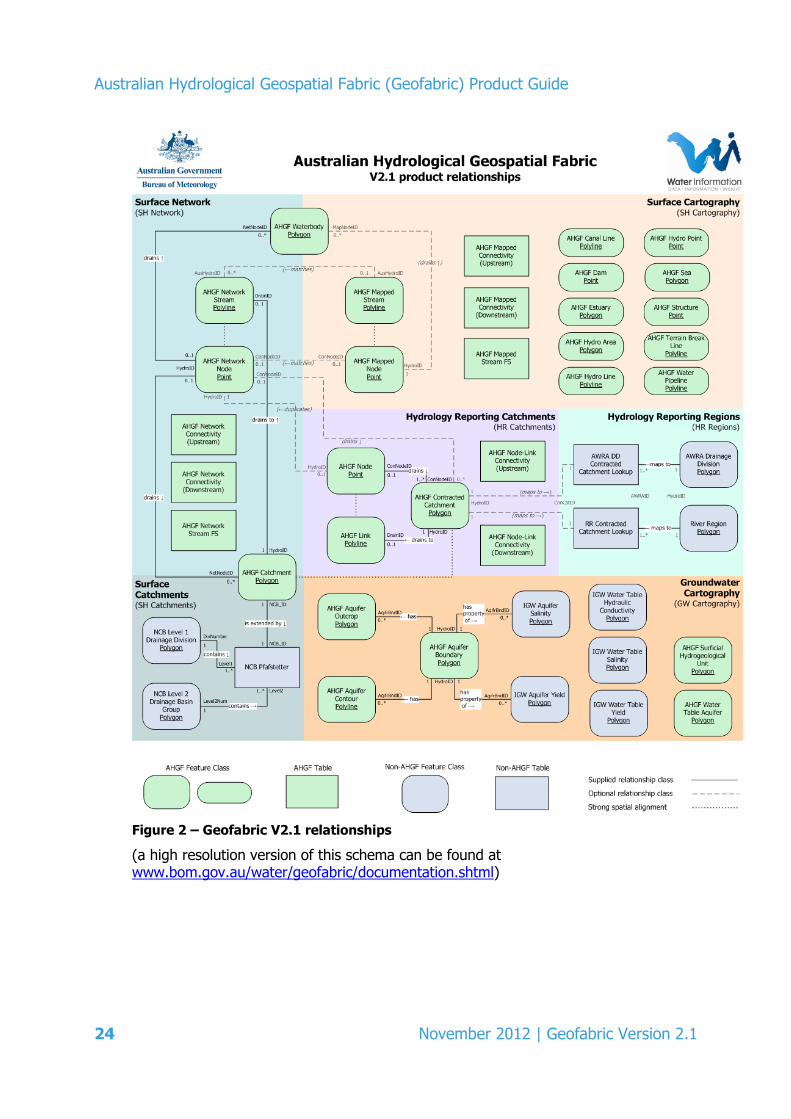
The products are ascribed to provide cross product integration by the use of related feature IDs, consistent naming conventions, and the application of contracted nodes that carry identity across products and between versions.
Figure 2 shows a model of the relationships between the features in the six Geofabric products providing an overview as to how these products both relate and, in some cases, overlap with one another.
Australian Hydrological Geospatial Fabric (Geofabric) Product Guide
24 November 2012 | Geofabric Version 2.1
Figure 2 – Geofabric V2.1 relationships
(a high resolution version of this schema can be found at www.bom.gov.au/water/geofabric/documentation.shtml)
Australian Hydrological Geospatial Fabric (Geofabric) Product Guide
November 2012 | Geofabric Version 2.1 25
3.2 Conceptual model supporting the Geofabric design
A conceptual model is an abstraction of phenomena, or features, in the real world. It describes the essential features, captures their relationships, and may also represent behaviour. The design of the Geofabric is based around a flexible and evolvable information model. This design requires:
A modular conceptual information model, capable of supporting many use cases and associated implementations as discussed in Atkinson et al (2008). This is the foundation on which implementations are developed.
Consistent use of standardised Data Product Specifications (DPS) describing both the dataset inputs and the derived data products output from the Geofabric.
Adoption of a nimble, iterative, requirements-focused development methodology that covers all aspects of the data product lifecycle and allows for evolution of technology, data products and user requirements.
The Geofabric design goal is to develop a single platform independent conceptual model that can be mapped to different implementation models as required. These implementation models can be structured to specifically support particular use cases.
The value of the conceptual model is that it is not influenced by the limitations of a chosen GIS implementation. Model development can focus on the phenomena being examined, how they are to be used and represented and their relationships to other phenomena. This means the underlying design of the Geofabric is based upon a repeatable information model and that the products are well documented and consistent in their behaviour over time.
The Geofabric conceptual model was developed according to International Organization for Standardization (ISO) conceptual modelling principles with a focus on modularity and re-use. It is specified in the Unified Modelling Language (UML) model with re-usable components clearly packaged. The Geofabric is the result of a physical implementation realising the concept model. Issues with data not being adequately expressed in the implementation (model) trigger a review of the conceptual model. Any redefinitions from this process flow to any derived data products. This ensures that any products derived from any platform specific implementation are able to rely on that product’s consistency and feature behaviour.
In Geofabric V2.1, there is only one platform specific implementation model that is based upon ArcGIS software using ESRI’s definitions of geodatabase models, schema, feature classes and relationship classes, etc. The products described in this Product Guide are derived from this implementation. Geofabric V2.1 conforms to the underlying conceptual model via the inclusion of a derived set of logical features, which represent contracted behaviours designed to persist over time.

Australian Hydrological Geospatial Fabric (Geofabric) Product Guide
26 November 2012 | Geofabric Version 2.1
4 Product overview
4.1 Product components
The Geofabric products consist of six distinct yet related geospatial datasets that are derived from the foundation input data. Specific spatial feature classes created by the Bureau also form a key part of the products. A list of the product geodatabase names, their file sizes and format is given in Table 4.
Table 4 – Product file sizes and formats
Product ~ File size (MegaBytes) Format
SH_Cartography.gdb 1020 ESRI File Geodatabase
SH_Network.gdb 1030 ESRI File Geodatabase
SH_Catchment.gdb 870 ESRI File Geodatabase
GW_Cartography.gdb 790 ESRI File Geodatabase
HR_Catchments.gdb 80 ESRI File Geodatabase
HR_Regions.gdb 20 ESRI File Geodatabase
The products are represented at a nominal scale of 1:250,000 in ESRI ArcGIS vector format and are delivered in an ESRI File Geodatabase format.
The products use the following geographic coordinate system:
Datum: Geographic Datum of Australia (GDA 94)
Geographic coordinate units: decimal degrees
Latitude resolution: 0.0000005
Longitude resolution: 0.0000005
A complete description of the data products’ spatial and geographic identifiers are contained within their accompanying Data Product Specification (DPS). The specifications are a formal description of the key features and attributes of each product and are based on the AS/NZS ISO 19131:2008 Geographic information – Data product specifications standard.
While the Geofabric products are delivered in a geographic coordinate system, it is recognised that users may need the data products to satisfy applications requiring differing units of measurement. For more information on selecting, reprojecting and using differing coordinate systems, please see:
http://webhelp.esri.com/arcgisdesktop/9.3/index.cfm?TopicName=About%20coordinate%20systems%20and%20map%20projections
The Geofabric is organised in a manner that reflects the standard spatial data hierarchy of the ESRI ArcGIS product suite for geodatabases. The Data Dictionaries and Data Product Specifications adhere to the standard ESRI data hierarchy nomenclature and conventions. This documentation assumes that the user is familiar with this data

Australian Hydrological Geospatial Fabric (Geofabric) Product Guide
November 2012 | Geofabric Version 2.1 27
structure, hierarchy and its components, such as geodatabase (the overall delivery data package), including:
feature dataset (a container for feature classes with shared properties and behaviours):
feature class by feature type (e.g. stream or water body represented by points, lines or polygons)
subtypes within the feature class (e.g. different types of water bodies within a water body feature class), i.e.:
attribution fields per each feature class and feature class subtype (the data fields that contain feature specific details)
attribute domains associated with feature class attributes to standardise the values for a given attribute field.
4.2 Relationships between Geofabric Surface Cartography and Geofabric Surface Network
Geofabric Surface Cartography and Geofabric Surface Network complement one another. Both are created from spatial data inputs that share definitions for stream segments and some feature attribution. The stream segmentation rules are based upon surface topographic features that are most likely to be common to both products. Whilst each product has its own set of unique attributes, the common attributes are limited to the simplest set of descriptors, e.g. common linked feature IDs, stream names and stream hierarchy. This means that the user can easily identify a stream segment in either product by a common ID, stream name (if it exists) or stream hierarchy (if it exists).
Geofabric Surface Network is intended to be used for the selection of hydrological observation points (if they exist) and as the source of stream segments for geoprocessing and hydrological modelling, whereas Geofabric Surface Cartography is intended for the production of maps which present the results of analyses.
Where there are equivalent mapped segments in Geofabric Surface Cartography to network segments in Geofabric Surface Network, an attempt was made to relate these through attribution. A complete set of attribution relationships is described in the individual sections of this Guide:
Section 5.1 Geofabric Surface Cartography
Section 5.2 Geofabric Surface Network
Section 5.3 Geofabric Surface Catchments
Section 5.4 Geofabric Groundwater Cartography
Section 5.5 Geofabric Hydrology Reporting Catchments
Section 5.6 Geofabric Hydrology Reporting Regions.

Australian Hydrological Geospatial Fabric (Geofabric) Product Guide
28 November 2012 | Geofabric Version 2.1
4.3 Spatial feature identifiers (IDs)
The field attribution of the six surface hydrology products includes a number of distinct identifier fields which serve different purposes. Each category of identifier can be described as follows:
SourceID/AusHydroID
All foundation input data products were supplied with a set of their own feature IDs. In order to maintain the link between the Geofabric and input features, these IDs are preserved as part of the feature level Geofabric metadata in an attribute field called SourceID.
The AusHydroID field included in the AHGFMappedStream and AHGFNetworkStream feature classes is a special case of SourceID. This ID provides one way of mapping stream features between Geofabric Surface Cartography and Geofabric Surface Network. While these IDs provide a useful way of locating the same stream segment in the two networks, these IDs are not persistent and may change between the Geofabric versions. The AusHydroIDs are further documented in the attribution of the Data Dictionaries.
HydroID
HydroIDs are specific and unique across the Geofabric products. They are created in the process of loading and post-processing the foundation data inputs into the Geofabric Maintenance Geodatabase. While these IDs are unique across all geodatabases within a Geofabric release, these IDs again are not persistent and are likely to change between the Geofabric versions. For more information on ArcHydro go to: resources.arcgis.com/content/hydrol
SegmentNo
The input foundation data products used to create the AHGFNetworkStream and AHGFCatchment feature classes included an identifier called SegmentNo. This identifier may be used to map AHGFNetworkStream features to related AHGFCatchment features or to relate vector features back to equivalent raster stream segments and catchments in the input foundation data products. Please note that no raster based Geofabric products are released in V1.0, V2.0 or V2.1.
ConNodeID (Contracted Node ID)
A process of identifying important hydrological features was used to determine a set of logical nodes which could be identified in both the stream networks within Geofabric Surface Cartography (AHGFNetworkNode) and Geofabric Surface Network (AHGFMappedNode). Each of these nodes was then assigned a unique identifier and a confidence level. These IDs (ConNodeID) and confidence levels (ConLevel) were attributed back to the corresponding representations of these nodes in the two stream networks, allowing identification of the logical nodes in both feature classes.

Australian Hydrological Geospatial Fabric (Geofabric) Product Guide
November 2012 | Geofabric Version 2.1 29
The idea of identifying a set of logical nodes and assigning them with a persistent identifier is aimed at providing the end-user with a set of contracted features that are likely to persist over time, regardless of any changes to the resolution and scale of future Geofabric product versions. The ConNodeID and ConLevel attributes are also assigned to the AHGFContractedCatchment feature class in Geofabric Hydrology Reporting Catchments. These features represent the sub-catchment areas drained by key contracted nodes.
4.4 Attributes common to all feature classes
As well as standard feature class metadata, each feature class also carries a standard set of attribute-level metadata, providing valuable information linking features to the foundation data. This allows the user to understand the data lineage and metadata that is available for the input products.
The following attributes, shown in Table 5, are common to all feature classes in the Geofabric products.
Table 5 – Feature class attributes common to all the Geofabric products
Field name
Alias name Reference from data input
HydroID Geofabric feature identifier, unique across all
geodatabases within an AHGF release
AHGFFType AHGFFeatureType Feature type within the AHGF Data Model
(e.g. 1: AHGFNetworkStream)
SrcFCName SourceFeatureClassName Feature class name from the input data source (e.g. Reservoirs)
SrcFType SourceFeatureType Feature type from the input data source
(e.g. TownRuralStorage)
SrcType SourceType Feature subtype (numeric code) from the input data
source (e.g. 2)
SourceID Unique identifier for individual feature in the input data source (e.g. 3023726)
FeatRel FeatureReliability Reliability date of spatial object. Adjusted during
spatial change/verification
FSource FeatureSource Name of agency that originally captured the spatial
object
AttrRel AttributeReliability Reliability date of attribute object. Adjusted during attribute change/verification
AttrSource AttributeSource Name of agency that originally captured the attribute
object
PlanAcc PlanimetricAccuracy Standard deviation of the horizontal positional
accuracy in metres (e.g. 100)
Symbol Symbol number for feature used in GA’s GEODATA product
TextNote Text note to accompany the feature

Australian Hydrological Geospatial Fabric (Geofabric) Product Guide
30 November 2012 | Geofabric Version 2.1
4.5 Geometric networks
Geometric networks are collections of line (edge) and point (junction) feature classes in a feature dataset that possess a connectivity relationship. Geometric networks provide extra behaviour to component features classes, in particular, an awareness that they are topologically connected to each other. Edges connect to other edges at junctions and in the network the flow from one edge to another is transferred through the junctions. When flow direction is set, flow can occur in only one direction.
A geometric network was built for Geofabric Surface Cartography, Geofabric Surface Network and Geofabric Hydrology Reporting Catchments. The networks are constructed from the respective node and stream (link for Geofabric Hydrology Reporting Catchments) feature classes, default parameters were used and flow direction was set.
Further information about geometric networks can be found at: http://help.arcgis.com/en/arcgisdesktop/10.0/help/index.html#//002r00000001000000.htm
4.6 Relationship classes
Relationship classes help ensure referential integrity between feature classes and allow for the query of related features.
The Geofabric contains a number of relationship classes and an example from the Geofabric Surface Network product is the relationship class CatchmentDrainsToSegment. This defines a drainage relationship between the (polygon) AHGFCatchment and (line) AHGFNetworkStream feature classes.
Further information about relationship classes can be found at:
http://help.arcgis.com/en/arcgisdesktop/10.0/help/index.html#/Benefits_of_relationship_classes/004t00000003000000/
4.7 Attribute domains
Attribute domains define rules for the allowable values for a specific attribute field. They help to enforce data integrity. Attribute domains can be either a range or coded value type. Range domains specify a valid range of values for a numeric domain, such as elevation. A coded value domain specifies a list of allowable values, such as State and Territory codes (WA, NT, etc).
Further information about attribute domains can be found at: http://help.arcgis.com/en/arcgisdesktop/10.0/help/index.html#/A_quick_tour_of_attribute_domains/001s00000001000000/

Australian Hydrological Geospatial Fabric (Geofabric) Product Guide
November 2012 | Geofabric Version 2.1 31
4.8 Attribute subtypes
A data subtype is a subset of features in a feature class which share the same allowable attributes or relationships. The use of subtypes allows for the allocation of an attribute domain and/or the definition of a relationship class to a subset of features within a feature class. The AHGFNetworkNode feature class within Geofabric Surface Network is an example of a feature class containing a number of subtypes.
Further information about subtypes can be found at:
http://help.arcgis.com/en/arcgisdesktop/10.0/help/index.html#/A_quick_tour_of_subtypes/005r00000001000000/

Australian Hydrological Geospatial Fabric (Geofabric) Product Guide
32 November 2012 | Geofabric Version 2.1
5 Product descriptions
The Geofabric V2.1 release comprises six products. Each of these products, and guidance on use, are described below.
5.1 Geofabric Surface Cartography
Geofabric Surface Cartography provides a set of related feature classes to be used as the basis for production of consistent hydrological cartographic maps. This product contains a geometric representation of the surface water features of Australia (excluding external Territories). These are largely natural surface hydrology features but some artificial features; notably dams, pipelines, reservoirs, canals and other hydrographic features, are also included.
The product may be used for visualisation of surface hydrology within a GIS to support the selection of features for inclusion in cartographic map production.
The product’s geometry is largely derived from a foundation input data product called AusHydro. Geofabric Surface Cartography includes water bodies such as swamps, reservoirs and lakes as derived from GEODATA 3, as well as the stream lines and their connectors through water bodies. Table 6 shows the Geofabric Surface Cartography feature class terminology and subtypes.
In addition, Geofabric Surface Cartography includes a set of contracted node attributes (embedded within AHGFMappedNode), which identify a subset of features common to both the cartographic stream network (AHGFMappedStream) and the topological stream network (AHGFNetworkStream). These attributes indicate the likely level of persistence for these features between Geofabric versions. The unique value-added feature of the contracted nodes is created by the Bureau and represents a persistent and coincident juncture between associated hydrologic features throughout the suite of products.
5.1.1 Understanding and using Geofabric Surface Cartography
Geofabric Surface Cartography is fully topologically correct. That is, the stream segments connect and flow in the correct direction (in relation to the overall stream line). Geofabric Surface Cartography represents the traditional sinuous blue line network and is designed to be used as a cartographic representation of Australian rivers and streams.
This product is suitable for users who need to analyse accurate stream length at a scale of 1:250,000.
The Geofabric Surface Cartography stream network and accompanying hydrological feature classes appear as similar to the GEODATA 3 hydrologic features. The nomenclature for the feature classes conforms to the Geofabric Surface Cartography data dictionary. The feature class nomenclature of Geofabric Surface Cartography is based upon the AusHydro data input which is derived from the GEODATA 3 hydrological feature classes. A complete mapping of the derived feature class nomenclature is described in the tables in Appendices 1 and 2.
Geofabric Surface Cartography can be used for any general GIS mapping or cartographic analysis available within the ArcGIS desktop environment. Features may be selected by
Australian Hydrological Geospatial Fabric (Geofabric) Product Guide
November 2012 | Geofabric Version 2.1 33
specific areas as described in Geofabric Surface Catchments, by boundaries, or by user-specified attributes such as stream names. Additionally, the geometric network supplied within the geodatabase can be used to do stream tracing operations.
Some applications of this product include:
producing maps for reporting
determining the locations of surface water features
determining the relationship of surface water features with one another and with other natural features in the landscape
intersecting areas of surface water features with gridded datasets to extract data
finding associated hydrological observations in a river network, i.e. determining where monitoring stations are located in relation to surface water features
running stream tracing operations using the geometric network.
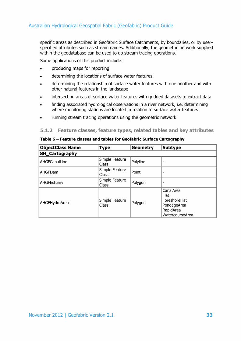
5.1.2 Feature classes, feature types, related tables and key attributes
Table 6 – Feature classes and tables for Geofabric Surface Cartography
ObjectClass Name Type Geometry Subtype
SH_Cartography
AHGFCanalLine Simple Feature Class
Polyline -
AHGFDam Simple Feature
Class Point -
AHGFEstuary Simple Feature
Class Polygon -
AHGFHydroArea Simple Feature Class
Polygon
CanalArea Flat
ForeshoreFlat PondageArea
RapidArea
WatercourseArea
Australian Hydrological Geospatial Fabric (Geofabric) Product Guide
34 November 2012 | Geofabric Version 2.1
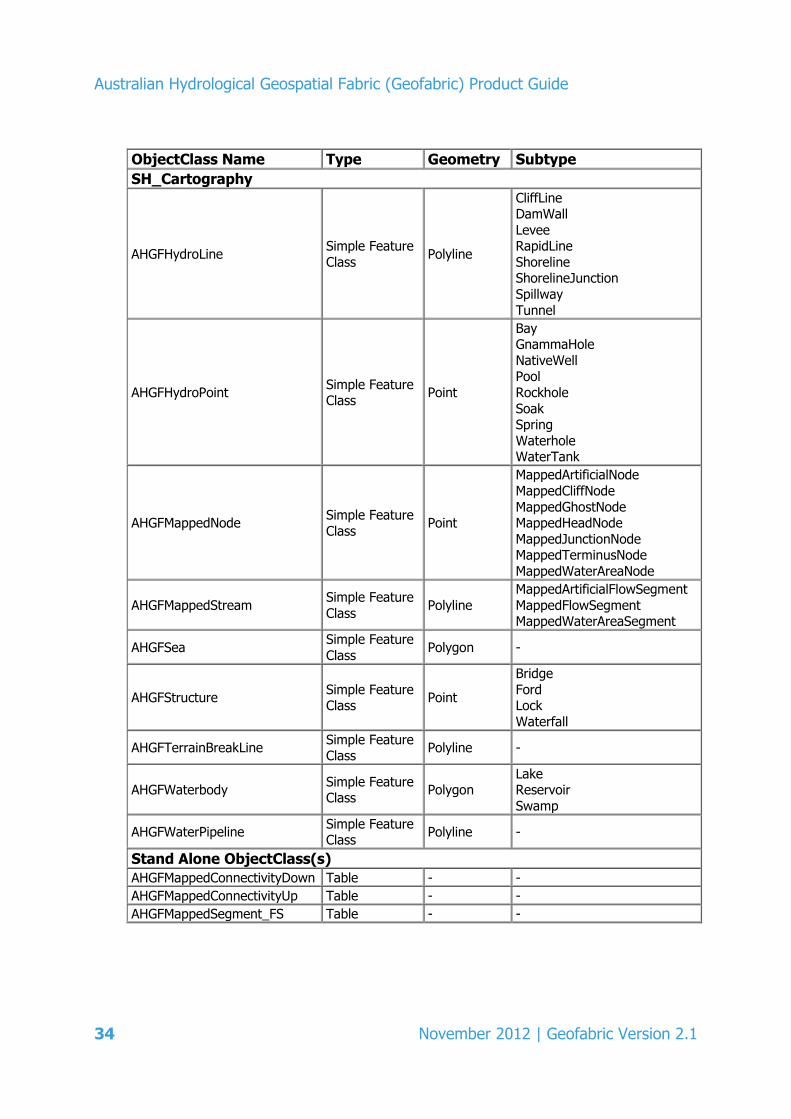
ObjectClass Name Type Geometry Subtype
SH_Cartography
AHGFHydroLine Simple Feature
Class Polyline
CliffLine DamWall
Levee RapidLine
Shoreline ShorelineJunction
Spillway
Tunnel
AHGFHydroPoint Simple Feature Class
Point
Bay GnammaHole
NativeWell Pool
Rockhole
Soak Spring
Waterhole WaterTank
AHGFMappedNode Simple Feature
Class Point
MappedArtificialNode
MappedCliffNode
MappedGhostNode MappedHeadNode
MappedJunctionNode MappedTerminusNode
MappedWaterAreaNode
AHGFMappedStream Simple Feature
Class Polyline
MappedArtificialFlowSegment
MappedFlowSegment MappedWaterAreaSegment
AHGFSea Simple Feature
Class Polygon -
AHGFStructure Simple Feature Class
Point
Bridge
Ford Lock
Waterfall
AHGFTerrainBreakLine Simple Feature Class
Polyline -
AHGFWaterbody Simple Feature Class
Polygon Lake Reservoir
Swamp
AHGFWaterPipeline Simple Feature Class
Polyline -
Stand Alone ObjectClass(s) AHGFMappedConnectivityDown Table - - AHGFMappedConnectivityUp Table - - AHGFMappedSegment_FS Table - -

Australian Hydrological Geospatial Fabric (Geofabric) Product Guide
November 2012 | Geofabric Version 2.1 35
Of the feature classes within Geofabric Surface Cartography, AHGFMappedNode is entirely created by the Bureau (from AHGFMappedStream) during the data input process. Both AHGFMappedNode and AHGFMappedStream feature classes contain Bureau designed subtypes which categorise the stream nodes and segments by type. AHGFMappedNode features represent the beginning or end node of a particular type of stream segment and are used to designate the transition of stream segment types. They generally indicate a specific break point in the stream network or the heads and termini of streams. The only AHGFMappedNode subtype which does not break the stream network segments is the MappedGhostNode.

Australian Hydrological Geospatial Fabric (Geofabric) Product Guide
36 November 2012 | Geofabric Version 2.1
Table 7 – Bureau generated feature classes (nodes and streams) included for Geofabric Surface Cartography
Feature class name FCGeometry Feature class subtype Description AHGFMappedNode Point MappedArtificialNode Represents the boundary where a MappedFlowSegment/
MappedWaterAreaSegment changes to/from a
MappedArtificialFlowHydroArea feature
MappedCliffNode Represents the locational break of a MappedStream segment intersection with an AHGFCliffline or
AHGFTerrainBreakLine
MappedGhostNode Used for building spatial relationships to monitoring points. This is the only mapped node feature which does not
coincide with a physical break in the stream segment network
MappedHeadNode The starting point of a MappedStream segment in the headwaters
MappedJunctionNode Any confluence/bifurcating node of two or more stream
segments
MappedTerminusNode Represents the terminal end point of any MappedStream
(i.e. coastal outlet or inland sink)
MappedWaterAreaNode Represents the entry or exit of a MappedArtificialFlow/ MappedArtificialFlowSegment into or out of an
AHGFWaterbody or AHGFHydroArea feature
AHGFMappedStream Polyline MappedArtificialFlowSegment Stream flow connectors that are not watercourse lines, i.e. connectors introduced to maintain certain key stream
connectivity
MappedFlowSegment Watercourse lines
MappedWaterAreaSegment Stream flow connectors that pass through a water area polygon

Australian Hydrological Geospatial Fabric (Geofabric) Product Guide
November 2012 | Geofabric Version 2.1 37
The following tables describe the key attributes for Geofabric Surface Cartography.
Table 8 – Key attributes of the AHGFMappedNode feature class for Geofabric
Surface Cartography
Key attribute Alias Description NextDownID NextDownID The HydroID for the next downstream stream mapped
node
ConNodeID ContractedNodeID Persistent unique identifier of related logical AHGF
contracted node
ConLevel ContractLevel Confidence level of related logical AHGF contracted node
NetNodeID NetworkNodeID The HydroID of the equivalent node in
AHGFNetworkNode
Table 9 – Key attributes of the AHGFMappedStream feature class for Geofabric
Surface Cartography
Key attribute Alias Description From_Node From_Node The HydroID for the AHGFMappedNode
To_Node To_Node The HydroID for the next downstream AHGFMappedNode
NextDownID NextDownID The HydroID for the next downstream AHGFMappedStream
segment
Table 10 – Key attributes of the AHGFMappedConnectivityDown (downstream) table
for Geofabric Surface Cartography
Key attribute Alias Description From_ID From_ID The HydroID for the AHGFMappedNode
To_ID To_ID The HydroID for the next downstream AHGFMappedNode
Segment_ID Segment_ID The HydroID for the corresponding AHGFMappedStream
segment
Table 11 – Key attributes of the AHGFMappedConnectivityUp (upstream) table for
Geofabric Surface Cartography
Key attribute Alias Description From_ID From_ID The HydroID for the AHGFMappedNode
To_ID To_ID The HydroID for the next upstream AHGFMappedNode
Segment_ID Segment_ID The HydroID for the corresponding AHGFMappedStream
segment
Table 12 – Key attributes of the AHGFMappedSegment_FS table for Geofabric Surface
Cartography (flow split table for use with ArcHydro tools)
Key attribute Alias Description FeatureID FeatureID The HydroID for an AHGFMappedStream segment
NextDownID NextDownID The HydroID for the next downstream AHGFMappedNode
Australian Hydrological Geospatial Fabric (Geofabric) Product Guide
38 November 2012 | Geofabric Version 2.1
5.2 Geofabric Surface Network
Geofabric Surface Network is based upon the input from ANUDEM Streams, which is the vectorised version of the nine second ANUDEM derived raster streams product. The ANUDEM algorithm is informed by the AusHydro foundation input data used to populate the AHGFMappedStream feature class in Geofabric Surface Cartography and thus is inherently related to this product.
Geofabric Surface Network is intended to be used in stream flow tracing operations, which utilise its full topological connection. The product can support the spatial selection of associated hydrological features (such as water bodies and catchments) as inputs for spatial analysis/modelling. Table 13 shows the Geofabric Surface Network feature class terminology and feature subtypes.
As with Geofabric Surface Cartography, the network product includes a set of contracted node attributes (embedded within AHGFNetworkNode), which identify a subset of features common to both of the two stream networks (AHGFNetworkStream and AHGFMappedStream). These attributes indicate the likely level of persistency for these features between the Geofabric versions.
5.2.1 Understanding and using Geofabric Surface Network
The Geofabric Surface Network stream network is related to, but distinct from, the stream network contained within Geofabric Surface Cartography. The network product represents the flow direction of Surface Cartography streams over the surface of the terrain, based upon a DEM-9S. It is more generalised and represents the main channels of the streams, particularly in areas where streams are heavily anabranched or disconnected.
In addition, the stream connectivity of Geofabric Surface Network represents a stream flow over the terrain, regardless of the presence of a corresponding Geofabric Surface Cartography stream segment. This means that Geofabric Surface Cartography may represent a stream as an interrupted or intermittent feature, whereas Geofabric Surface Network represents the same stream as a continuous connected feature, i.e. the path that stream would take (according to the terrain model) if sufficient water were available for flow.
A complete mapping of the derived feature class nomenclature is described in the tables in Appendices 1 and 2.

Australian Hydrological Geospatial Fabric (Geofabric) Product Guide
November 2012 | Geofabric Version 2.1 39
Some applications for this product include:
locating associated hydrological observations (monitoring points) in a river network
tracing connectivity between hydrological features
stream flow modelling
selecting related features up or downstream of a point such as water bodies or catchments
accumulating attribute values of upstream or downstream related features, e.g. calculating average stream heights upstream of a point.
5.2.2 Feature classes, feature types, related tables and key attributes
Table 13 - Feature classes and tables for Geofabric Surface Network
ObjectClass Name Type Geometry Subtype
SH_Network
AHGFCatchment Simple
FeatureClass Polygon -
AHGFNetworkNode Simple
FeatureClass Point
NetworkArtificialNode
NetworkCliffNode NetworkGhostNode
NetworkHeadNode NetworkJunctionNode
NetworkTerminusNode NetworkWaterAreaNode
AHGFNetworkStream Simple FeatureClass
Polyline NetworkArtificialFlowSegment NetworkFlowSegment
NetworkWaterAreaSegment
AHGFWaterbody Simple
FeatureClass Polygon
Lake Reservoir
Swamp Stand Alone ObjectClass(s) AHGFNetworkConnectivityDown Table - - AHGFNetworkConnectivityUp Table - - AHGFNetworkStream_FS Table - -
Of the feature classes within Geofabric Surface Network, AHGFNetworkNode is entirely created by the Bureau (from AHGFNetworkStream) during the data input process.
Both AHGFNetworkNode and AHGFNetworkStream feature classes contain Bureau designed subtypes and field attribution which categorise the stream nodes and segments by type and facilitate their use in stream network analysis.
AHGFNetworkNode features represent the beginning or end node of a particular type of stream segment and are used to designate the transition of stream segment types. They generally indicate a specific break point in the stream network or the heads and termini

Australian Hydrological Geospatial Fabric (Geofabric) Product Guide
40 November 2012 | Geofabric Version 2.1
of streams. The only AHGFNetworkNode subtype that does not break the stream network segments is the NetworkGhostNode.

Australian Hydrological Geospatial Fabric (Geofabric) Product Guide
November 2011 | Geofabric Version 2.0 41
Table 14 – Bureau generated feature classes (nodes and streams) included for Geofabric Surface Network
Feature class name FCGeometry Feature class subtype Description AHGFNetworkNode Point NetworkArtificialNode Represents the boundary where a NetworkFlowSegment/
NetworkWaterAreaSegment changes to/from a
NetworkArtificialFlowHydroArea feature
NetworkCliffNode Represents the locational break of a NetworkStream segment intersection with an AHGFCliffline or
AHGFTerrainBreakLine
NetworkGhostNode Used for building spatial relationships to monitoring points. This is the only network node feature which does
not coincide with a physical break in the stream segment network
NetworkHeadNode The starting point of a NetworkStream segment in the
headwaters
NetworkJunctionNode Any confluence/bifurcating node of two or more stream
segments
NetworkTerminusNode Represents the terminal end-point of any NetworkStream segment (i.e. coastal outlet or inland sink)
NetworkWaterAreaNode Represents the entry or exit of an AHGFNetworkStream into or out of an AHGFWaterbody or AHGFHydroArea
feature
AHGFNetworkStream Polyline NetworkArtificialFlowSegment Stream flow connectors that are not watercourse lines, i.e. derived connectors which maintain the stream
network connectivity between NetworkFlowSegment features but have no corresponding feature in
AHGFMappedStream
NetworkFlowSegment ANUDEM vectorised stream segments that correspond to
MappedFlowSegment features
NetworkWaterAreaSegment Stream flow connectors that pass through a water area
polygon and coincide with a MappedFlowSegment in AHGFMappedStream

Australian Hydrological Geospatial Fabric (Geofabric) Product Guide
42 November 2012 | Geofabric Version 2.1
The following tables describe the key attributes for Geofabric Surface Network.
Table 15 – Key attributes of the AHGFNetworkNode feature class for Geofabric
Surface Network
Key attribute Alias Description NextDownID NextDownID The HydroID for the next downstream stream network
node
ConNodeID ContractedNodeID Persistent unique identifier of related logical AHGF
contracted node
ConLevel ContractLevel Confidence level of related logical AHGF contracted node
MapNodeID MappedNodeID The HydroID of the equivalent node in
AHGFMappedNode
Table 16 – Key attributes of the AHGFNetworkStream feature class for Geofabric
Surface Network
Key attribute Alias Description SegmentNo SegmentNo Identifier of related raster stream segment in input data
source
DrainID DrainID The HydroID for the AHGFCatchment in to which the AHGFNetworkStream drains
From_Node From_Node The HydroID for the AHGFNetworkNode
To_Node To_Node The HydroID for the next downstream AHGFNetworkNode
NextDownID NextDownID The HydroID for the next downstream AHGFNetworkStream feature
Table 17 – Key attributes of the AHGFNetworkConnectivityDown (downstream)
table for Geofabric Surface Network
Key attribute Alias Description From_ID From_ID The HydroID for the AHGFNetworkNode
To_ID To_ID The HydroID for the next downstream AHGFNetworkNode
Segment_ID Segment_ID The HydroID for the corresponding AHGFNetworkStream
feature
Table 18 – Key attributes of the AHGFNetworkConnectivityUp (upstream) table for
Geofabric Surface Network
Key attribute Alias Description From_ID From_ID The HydroID for the AHGFNetworkNode
To_ID To_ID The HydroID for the next upstream AHGFNetworkNode
Segment_ID Segment_ID The HydroID for the corresponding AHGFNetworkStream
feature
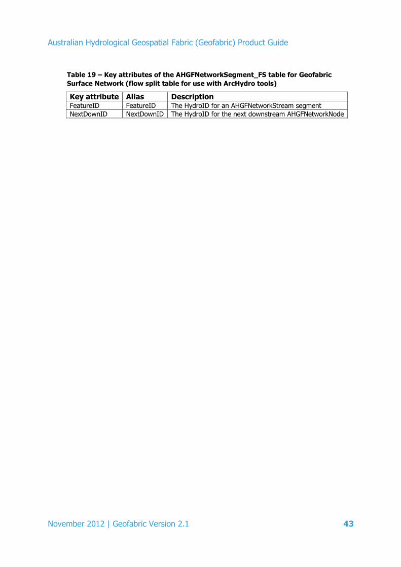
Australian Hydrological Geospatial Fabric (Geofabric) Product Guide
November 2012 | Geofabric Version 2.1 43
Table 19 – Key attributes of the AHGFNetworkSegment_FS table for Geofabric
Surface Network (flow split table for use with ArcHydro tools)
Key attribute Alias Description FeatureID FeatureID The HydroID for an AHGFNetworkStream segment
NextDownID NextDownID The HydroID for the next downstream AHGFNetworkNode
Australian Hydrological Geospatial Fabric (Geofabric) Product Guide
44 November 2012 | Geofabric Version 2.1
5.3 Geofabric Surface Catchments
The feature class contained within this data product is based upon the stream segment level catchments of the NCB foundation input data. These data define a catchment for every stream segment contained within Geofabric Surface Network (AHGFNetworkStream) according to DEM-9S. It is these catchments which serve as direct input into the AHGFCatchment feature class. Table 20 shows the Geofabric Surface Catchments feature class terminology and feature subtypes. A complete mapping of the derived feature class nomenclature is described in the tables in Appendices 1 and 2.
5.3.1 Understanding and using Geofabric Surface Catchments
The AHGFCatchment feature class is designed to represent geographic surface boundaries that have a hydrological relationship to surface water features. These catchment boundaries in their current form may not completely satisfy legislative or local government requirements, but they may be used for surface hydrological analysis. Some of these applications include:
providing a system boundary for surface water modelling
identifying areas of interest for reporting
producing maps for reporting
aggregating small catchments to form required hydrological modelling boundaries.
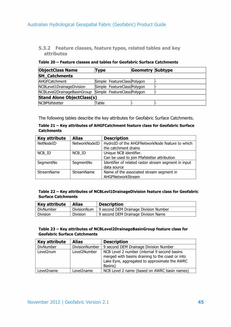
Australian Hydrological Geospatial Fabric (Geofabric) Product Guide
November 2012 | Geofabric Version 2.1 45
5.3.2 Feature classes, feature types, related tables and key attributes
Table 20 – Feature classes and tables for Geofabric Surface Catchments
ObjectClass Name Type Geometry Subtype
SH_Catchments AHGFCatchment Simple FeatureClass Polygon - NCBLevel1DrainageDivision Simple FeatureClass Polygon - NCBLevel2DrainageBasinGroup Simple FeatureClass Polygon -
Stand Alone ObjectClass(s) NCBPfafstetter Table - -
The following tables describe the key attributes for Geofabric Surface Catchments.
Table 21 – Key attributes of AHGFCatchment feature class for Geofabric Surface
Catchments
Key attribute Alias Description NetNodeID NetworkNodeID HydroID of the AHGFNetworkNode feature to which
the catchment drains
NCB_ID NCB_ID Unique NCB identifier.
Can be used to join Pfafstetter attribution
SegmentNo SegmentNo Identifier of related raster stream segment in input data source
StreamName StreamName Name of the associated stream segment in
AHGFNetworkStream
Table 22 – Key attributes of NCBLevl1DrainageDivision feature class for Geofabric
Surface Catchments
Key attribute Alias Description DivNumber DivisionNum 9 second DEM Drainage Division Number
Division Division 9 second DEM Drainage Division Name
Table 23 – Key attributes of NCBLevel2DrainageBasinGroup feature class for
Geofabric Surface Catchments
Key attribute Alias Description DivNumber DivisionNumber 9 second DEM Drainage Division Number
Level2num Level2Number NCB Level 2 number (internal 9 second basins merged with basins draining to the coast or into
Lake Eyre, aggregated to approximate the AWRC Basins)
Level2name Level2name NCB Level 2 name (based on AWRC basin names)
Australian Hydrological Geospatial Fabric (Geofabric) Product Guide
46 November 2012 | Geofabric Version 2.1
5.3.3 Using the base level catchments with extended Pfafstetter attribution
The Geofabric Surface Catchments delineate hierarchically-nested catchments derived using an automated drainage analysis procedure based on a multi-flow extension of the GEODATA 9 Second Flow Direction Grid (D8-9S) associated with the DEM-9S (ANU Fenner School of Environment and Society and GA 2008).
At the highest levels in the hierarchy, the Geofabric Surface Catchments aggregate the nine second drainage basins into 12 topographically defined drainage divisions (Level 1) and 191 catchment units (Level 2) approximating the drainage basins from GA (1997) where possible. At lower levels, the Level 2 catchment units are subdivided into successively finer sub-catchments using a modified version of the Pfafstetter procedure (Stein, Hutchinson & Stein 2008a; Stein & Hutchinson 2008b).
The Pfafstetter reference system is supplied as part of Geofabric Surface Catchments. The NCBPfafstetter table can be used to extend (via a join on NCB_ID) the set of attributions present in AHGFCatchment with the Pfafstetter attribution. Attribute descriptions for the Pfafstetter table is given in Appendix 3.
5.3.4 NCBLevel1DrainageDivison and NCBLevel2DrainageBasinGroup
Geofabric Surface Catchments provides a hierarchy of nested catchments from drainage divisions at the top level all the way down to a separate catchment for every stream segment in Geofabric Surface Network.
The top two levels of this hierarchy, Level 1 and Level 2, have been extracted as separate feature classes. The NCBLevel1DrainageDivision feature class consists of 12 topographically defined drainage divisions and represent the highest level of the catchment hierarchy.
At the next level down, the NCBLevel2DrainageBasinGroup represent 191 catchment units approximating the Australian Water Resources Management Committee (WRMC) river basins as described in GA (1997).
Australian Hydrological Geospatial Fabric (Geofabric) Product Guide
November 2012 | Geofabric Version 2.1 47
5.4 Geofabric Groundwater Cartography
Geofabric Groundwater Cartography is a national groundwater dataset bringing together existing groundwater mapping by collating and integrating the best available, Commonwealth, State and Territory and regional groundwater mapping datasets across Australia. Although there are some gaps in the information, every effort was made to reduce or minimise inconsistencies and conflicts in overlapping and abutting datasets and in attribution and definitions of the input datasets.
In generating the various national aquifer datasets, an interim national groundwater (IGW) framework was developed to relate geological units and regional and State and Territory groundwater aquifer mapping units to a nationally consistent set of aquifers and aquitards.
The purpose of this framework is to provide a transparent mapping of aquifers from geological units, State and Territory or regional groundwater aquifer mapping (where available) and the interim national product. Such an approach was necessary to resolve inconsistencies in aquifer naming and definition across State and Territory borders.
Table 24 shows the Geofabric Groundwater Cartography feature class terminology and feature subtypes.
5.4.1 Understanding and using Geofabric Groundwater Cartography
Geofabric Groundwater Cartography was developed to collate and integrate State and Territory and regional groundwater mapping datasets across Australia. The dataset is intended to be used at the regional to national scale and does not support local scale groundwater conceptualisation and modelling. It has not incorporated local and regional groundwater modelling data.
Geofabric Groundwater Cartography was generated from available groundwater mapping data from the various State and Territory jurisdictions. Given the interim nature of Geofabric Groundwater Cartography, no groundwater borehole data were collated or reviewed in its generation.
Some of the applications of Geofabric Groundwater Cartography include:
cartographic map production
groundwater hydrologic analysis
groundwater feature visualisation.
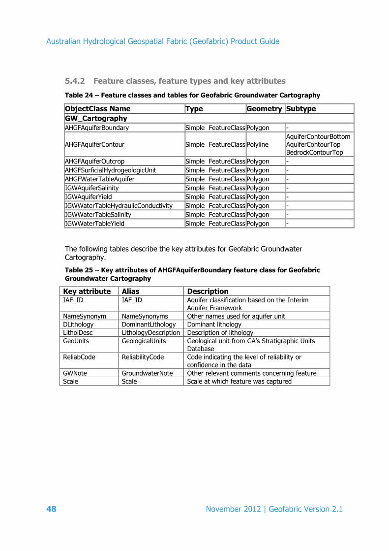
Australian Hydrological Geospatial Fabric (Geofabric) Product Guide
48 November 2012 | Geofabric Version 2.1
5.4.2 Feature classes, feature types and key attributes
Table 24 – Feature classes and tables for Geofabric Groundwater Cartography
ObjectClass Name Type Geometry Subtype
GW_Cartography AHGFAquiferBoundary Simple FeatureClass Polygon -
AHGFAquiferContour Simple FeatureClass Polyline AquiferContourBottom AquiferContourTop
BedrockContourTop AHGFAquiferOutcrop Simple FeatureClass Polygon - AHGFSurficialHydrogeologicUnit Simple FeatureClass Polygon - AHGFWaterTableAquifer Simple FeatureClass Polygon - IGWAquiferSalinity Simple FeatureClass Polygon - IGWAquiferYield Simple FeatureClass Polygon - IGWWaterTableHydraulicConductivity Simple FeatureClass Polygon -
IGWWaterTableSalinity Simple FeatureClass Polygon -
IGWWaterTableYield Simple FeatureClass Polygon -
The following tables describe the key attributes for Geofabric Groundwater Cartography.
Table 25 – Key attributes of AHGFAquiferBoundary feature class for Geofabric
Groundwater Cartography
Key attribute Alias Description IAF_ID IAF_ID Aquifer classification based on the Interim
Aquifer Framework
NameSynonym NameSynonyms Other names used for aquifer unit
DLithology DominantLithology Dominant lithology
LitholDesc LithologyDescription Description of lithology
GeoUnits GeologicalUnits Geological unit from GA’s Stratigraphic Units Database
ReliabCode ReliabilityCode Code indicating the level of reliability or
confidence in the data
GWNote GroundwaterNote Other relevant comments concerning feature
Scale Scale Scale at which feature was captured
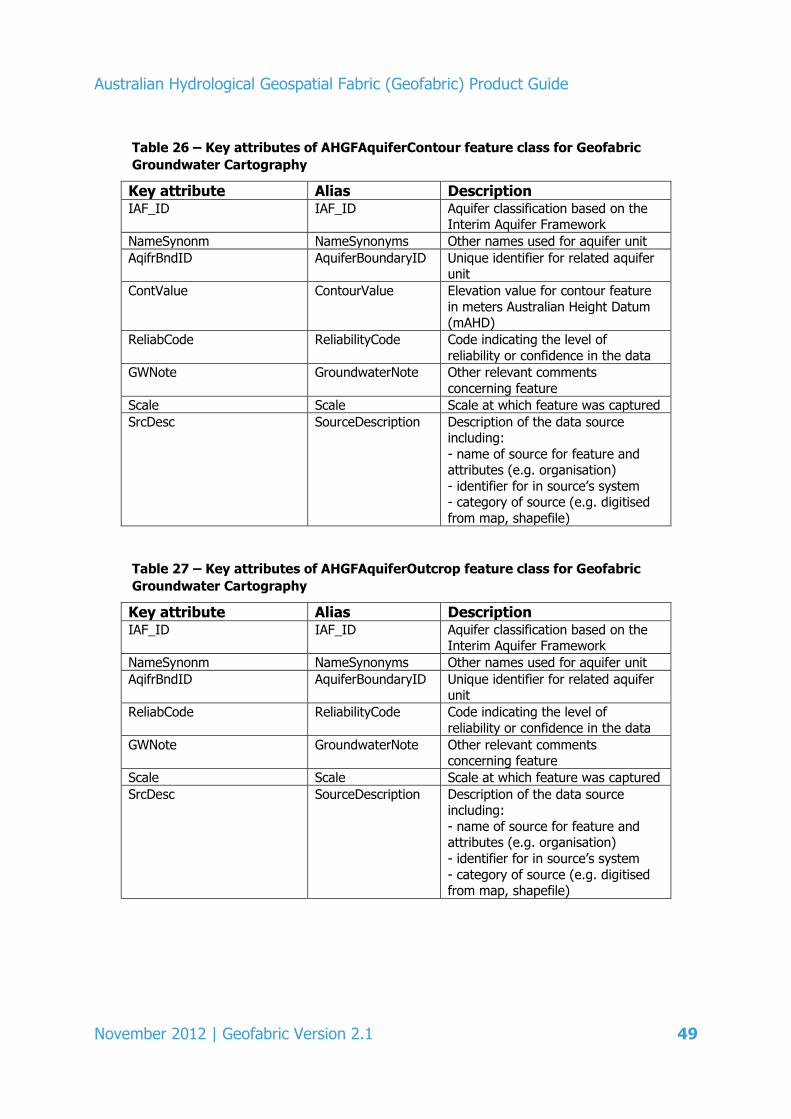
Australian Hydrological Geospatial Fabric (Geofabric) Product Guide
November 2012 | Geofabric Version 2.1 49
Table 26 – Key attributes of AHGFAquiferContour feature class for Geofabric
Groundwater Cartography
Key attribute Alias Description IAF_ID IAF_ID Aquifer classification based on the
Interim Aquifer Framework
NameSynonm NameSynonyms Other names used for aquifer unit
AqifrBndID AquiferBoundaryID Unique identifier for related aquifer unit
ContValue ContourValue Elevation value for contour feature
in meters Australian Height Datum (mAHD)
ReliabCode ReliabilityCode Code indicating the level of
reliability or confidence in the data
GWNote GroundwaterNote Other relevant comments
concerning feature
Scale Scale Scale at which feature was captured
SrcDesc SourceDescription Description of the data source including:
- name of source for feature and attributes (e.g. organisation)
- identifier for in source’s system - category of source (e.g. digitised
from map, shapefile)
Table 27 – Key attributes of AHGFAquiferOutcrop feature class for Geofabric
Groundwater Cartography
Key attribute Alias Description IAF_ID IAF_ID Aquifer classification based on the
Interim Aquifer Framework
NameSynonm NameSynonyms Other names used for aquifer unit
AqifrBndID AquiferBoundaryID Unique identifier for related aquifer unit
ReliabCode ReliabilityCode Code indicating the level of
reliability or confidence in the data
GWNote GroundwaterNote Other relevant comments concerning feature
Scale Scale Scale at which feature was captured
SrcDesc SourceDescription Description of the data source including:
- name of source for feature and attributes (e.g. organisation)
- identifier for in source’s system
- category of source (e.g. digitised from map, shapefile)
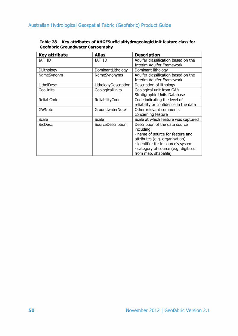
Australian Hydrological Geospatial Fabric (Geofabric) Product Guide
50 November 2012 | Geofabric Version 2.1
Table 28 – Key attributes of AHGFSurficialHydrogeologicUnit feature class for
Geofabric Groundwater Cartography
Key attribute Alias Description IAF_ID IAF_ID Aquifer classification based on the
Interim Aquifer Framework
DLithology DominantLithology Dominant lithology
NameSynonm NameSynonyms Aquifer classification based on the Interim Aquifer Framework
LitholDesc LithologyDescription Description of lithology
GeoUnits GeologicalUnits Geological unit from GA’s Stratigraphic Units Database
ReliabCode ReliabilityCode Code indicating the level of
reliability or confidence in the data
GWNote GroundwaterNote Other relevant comments concerning feature
Scale Scale Scale at which feature was captured
SrcDesc SourceDescription Description of the data source including:
- name of source for feature and attributes (e.g. organisation)
- identifier for in source’s system
- category of source (e.g. digitised from map, shapefile)

Australian Hydrological Geospatial Fabric (Geofabric) Product Guide
November 2012 | Geofabric Version 2.1 51
Table 29 – Key attributes of AHGFWaterTableAquifer feature class for Geofabric
Groundwater Cartography
Key attribute Alias Description IAF_ID IAF_ID Aquifer classification based on
the Interim Aquifer Framework
NameSynonm NameSynonyms Other names used for aquifer
unit
GWProvince GroundwaterProvince Groundwater province
GWFlowSysP GWFlowSystemPrimary Primary scale of groundwater
flow system
GWFlowSysS GWFlowSystemSecondary Secondary scale of groundwater
flow system
ReliabCode ReliabilityCode Code indicating the level of reliability or confidence in the
data
GwNote GroundwaterNote Other relevant comments concerning feature
Scale Scale Scale at which feature was
captured
SrcDesc SourceDescription Description of the data source
including:
- name of source for feature and attributes (e.g.
organisation) - identifier for in source’s
system
- category of source (e.g. digitized from map, shapefile)

Australian Hydrological Geospatial Fabric (Geofabric) Product Guide
52 November 2012 | Geofabric Version 2.1
Table 30 – Key attributes of IGWAquiferSalinity feature class for Geofabric
Groundwater Cartography
Key attribute Alias Description IAF_ID IAF_ID Aquifer classification based on the
Interim Aquifer Framework
NameSynonm NameSynonyms Other names used for aquifer unit
AqifrBndID AquiferBoundaryID Unique identifier for related aquifer unit
SalinValue SalinityValue Salinity range in mg/L (milligrams
per litre)
SalinClass SalinityClass Category for salinity (e.g. saline,
non-saline)
SalinMin SalinityMinimum Minimum value for salinity in mg/L (milligrams per litre)
SalinMax SalinityMaximum Maximum value for salinity in mg/L
(milligrams per litre)
SalinMed SalinityMedian Median value for salinity in mg/L (milligrams per litre)
ReliabCode ReliabilityCode Code indicating the level of reliability or confidence in the data
GWNote GroundwaterNote Other relevant comments
concerning feature
Scale Scale Scale at which feature was captured
SrcDesc SourceDescription Description of the data source
including: - name of source for feature and
attributes (e.g. organisation)
- identifier for in source’s system - category of source (e.g. digitised
from map, shapefile)

Australian Hydrological Geospatial Fabric (Geofabric) Product Guide
November 2012 | Geofabric Version 2.1 53
Table 31 – Key attributes of IGWAquiferYield feature class for Geofabric
Groundwater Cartography
Key attribute Alias Description IAF_ID IAF_ID Aquifer classification based on the
Interim Aquifer Framework
NameSynonm NameSynonyms Other names used for aquifer unit
AqifrBndID AquiferBoundaryID Unique identifier for related aquifer unit
YieldValue YieldValue Bore yield range in L/s (litres per
second)
YieldClass YieldClass Category for bore yield (e.g. <5L/s,
>5L/s)
YieldMin YieldMinimum Minimum value for bore yield in L/s (litres per second)
YieldMax YieldMaximum Maximum value for bore yield in L/s
(litres per second)
YieldMed YieldMedian Median value for bore yield in L/s (litres per second)
ReliabCode ReliabilityCode Code indicating the level of reliability or confidence in the data
GWNote GroundwaterNote Other relevant comments
concerning feature
Scale Scale Scale at which feature was captured
SrcDesc SourceDescription Description of the data source
including: - name of source for feature and
attributes (e.g. organisation)
- identifier for in source’s system - category of source (e.g. digitised
from map, shapefile)

Australian Hydrological Geospatial Fabric (Geofabric) Product Guide
54 November 2012 | Geofabric Version 2.1
Table 32 – Key attributes of IGWWaterTableHydraulicConductivity feature class for
Geofabric Groundwater Cartography
Key attribute Alias Description IAF_ID IAF_ID Aquifer classification based on the
Interim Aquifer Framework
HydKValue HydraulicConductivityValue Range for hydraulic conductivity in
m/d (metres/day)
SpecYield SpecificBoreYield Range for specific yield (unitless)
ReliabCode ReliabilityCode Code indicating the level of reliability
or confidence in the data
GWNote GroundwaterNote Other relevant comments concerning
feature
Scale Scale Scale at which feature was captured
SrcDesc SourceDescription Description of the data source including:
- name of source for feature and attributes (e.g. organisation)
- identifier for in source’s system
- category of source (e.g. digitised from map, shapefile)
Table 33 – Key attributes of IGWWaterTableSalinity feature class for Geofabric
Groundwater Cartography
Key attribute Alias Description SalinValue SalinityValue Salinity range in mg/L (milligrams per
litre)
SalinClass SalinityClass Category for salinity (e.g. saline, non-
saline)
SalinMin SalinityMinimum Minimum value for salinity in mg/L (milligrams per litre)
SalinMax SalinityMaximum Maximum value for salinity in mg/L (milligrams per litre)
SalinMed SalinityMedian Median value for salinity in mg/L
(milligrams per litre)
ReliabCode ReliabilityCode Code indicating the level of reliability or confidence in the data
GWNote GroundwaterNote Other relevant comments concerning feature
Scale Scale Scale at which feature was captured
SrcDesc SourceDescription Description of the data source
including: - name of source for feature and
attributes (e.g. organisation) - identifier for in source’s system
- category of source (e.g. digitised from map, shapefile)
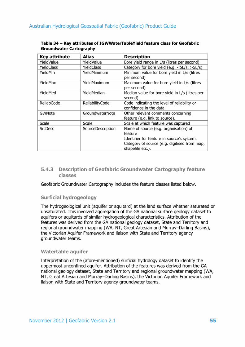
Australian Hydrological Geospatial Fabric (Geofabric) Product Guide
November 2012 | Geofabric Version 2.1 55
Table 34 – Key attributes of IGWWaterTableYield feature class for Geofabric
Groundwater Cartography
Key attribute Alias Description YieldValue YieldValue Bore yield range in L/s (litres per second)
YieldClass YieldClass Category for bore yield (e.g. <5L/s, >5L/s)
YieldMin YieldMinimum Minimum value for bore yield in L/s (litres
per second)
YieldMax YieldMaximum Maximum value for bore yield in L/s (litres per second)
YieldMed YieldMedian Median value for bore yield in L/s (litres per second)
ReliabCode ReliabilityCode Code indicating the level of reliability or
confidence in the data
GWNote GroundwaterNote Other relevant comments concerning feature (e.g. link to source).
Scale Scale Scale at which feature was captured
SrcDesc SourceDescription Name of source (e.g. organisation) of feature
Identifier for feature in source’s system. Category of source (e.g. digitised from map,
shapefile etc.).
5.4.3 Description of Geofabric Groundwater Cartography feature classes
Geofabric Groundwater Cartography includes the feature classes listed below.
Surficial hydrogeology
The hydrogeological unit (aquifer or aquitard) at the land surface whether saturated or unsaturated. This involved aggregation of the GA national surface geology dataset to aquifers or aquitards of similar hydrogeological characteristics. Attribution of the features was derived from the GA national geology dataset, State and Territory and regional groundwater mapping (WA, NT, Great Artesian and Murray–Darling Basins), the Victorian Aquifer Framework and liaison with State and Territory agency groundwater teams.
Watertable aquifer
Interpretation of the (afore-mentioned) surficial hydrology dataset to identify the uppermost unconfined aquifer. Attribution of the features was derived from the GA national geology dataset, State and Territory and regional groundwater mapping (WA, NT, Great Artesian and Murray–Darling Basins), the Victorian Aquifer Framework and liaison with State and Territory agency groundwater teams.

Australian Hydrological Geospatial Fabric (Geofabric) Product Guide
56 November 2012 | Geofabric Version 2.1
Watertable hydraulic conductivity
This dataset depicts hydraulic conductivity and specific yield for various groundwater flow systems defined as part of the CSIRO Commercial Environmental Forestry program. In some cases, the groundwater flow system contains a number of different component geologies which have different hydraulic characteristics. Therefore, the stated aquifer hydraulic conductivity and specific yield are indicative only and should be considered to be representative of the dominant geology contained within each groundwater flow system.
Watertable salinity
Collation of watertable salinity mapping (where available) at State and Territory and regional scale. The watertable aquifer was defined by the source datasets. Units are mg/L.
Watertable yield
Collation of watertable yield mapping (where available) at State and Territory and regional scale. The watertable aquifer was defined by the source datasets. Units are L/s.
Aquifer boundaries
Collation of available aquifer extent boundaries (where available) at State and Territory and regional scale. The extent of the dataset relates to the availability of data. The aquifers defined in the source groundwater mapping were retained and related to the interim aquifer framework (IAF).
Aquifer salinity
Collation of aquifer salinity mapping (where available) at State and Territory and regional scale for confined and unconfined aquifers in the aquifer boundary dataset. The aquifers defined in the source groundwater mapping were retained and related to the IAF aquifers. Units are mg/L.
Aquifer yield
Collation of underlying aquifer yield mapping (where available) at a regional scale. The aquifers defined in the source groundwater mapping were retained and related to the IAF. Units are L/s.
Aquifer structure contours
Collation of available elevation contours for the top and bottom of aquifers (where available) mapped at a regional scale. The presence and absence of contours relates to the availability of data. Units are elevation in metres Australian Height Datum (mAHD).

Australian Hydrological Geospatial Fabric (Geofabric) Product Guide
November 2012 | Geofabric Version 2.1 57
The aquifers defined in the source groundwater mapping were retained and related to the IAF aquifers.
Aquifer outcrop
Outcropping portion of aquifers which are confined for at least some of their extent. The outcrop can be considered to be the intake areas for rainfall recharge to the otherwise, confined aquifers. The Aquifer outcrop and the watertable aquifer polygons are co-incident where the aquifer is unconfined.
Australian Hydrological Geospatial Fabric (Geofabric) Product Guide
58 November 2012 | Geofabric Version 2.1
5.5 Geofabric Hydrology Reporting Catchments
Geofabric Hydrology Reporting Catchments comprises two related views of hydrological catchments to be used for analysis and reporting purposes. Firstly, a topological network view of hydrological catchments represented as a simplified node-link network using a subset of the contracted nodes (AHGFNode) and the links (AHGFLink) between them; and secondly, a catchments view of the hydrology using the contracted catchments (AHGFContractedCatchment).
The AHGFNode feature class contains contracted nodes that are points of hydrological significance that carry identity. They include the confluence of major named streams, coastal stream termini, waterbody inflow and outflows and inland sinks. It also contains a new class of node called diffuse nodes that represent diffused flow from groups of nodes at coastal, delta or inter-catchment outlets.
The AHGFLink feature class provides the topological connectors between a subset of contracted nodes that participate in the simplified node-link network.
The AHGFContractedCatchment feature class contains catchment polygons (that are aggregations of AHGFCatchments) for the subset of contracted nodes that participate in the simplified node link network. These catchments are part of a hierarchy that can be aggregated based on upstream relationships. Table 35 shows the Geofabric Hydrology Reporting Catchments feature class terminology and feature subtypes. A complete mapping of the derived feature class nomenclature is described in the tables in Appendices 1 and 2.
The AHGFContractedCatchments can be subdivided by type as follows:
ContractedArea – the upstream catchment area draining to a contracted node that participates in the simplified node-link network. It identifies the area upstream that will drain to that node (bounded wherever other upstream contracted nodes are encountered).
NonContractedArea – the upstream catchment area draining to areas with contracted nodes of low confidence level (i.e. catchments containing AHGFNetworkStream features without corresponding AHGFMappedStream features)
NoFlowArea – areas lacking both related network stream features and sensible catchments with which to be merged such as small islands.
5.5.1 Understanding and using Geofabric Hydrology Reporting Catchments
Geofabric Hydrology Reporting Catchments is designed to meet two specific use cases. Firstly, the contracted catchments are designed to build stable reporting regions and secondly, the simplified node-link network is designed to be used as input to hydrological modelling environments, to identify nodes, reporting reaches and their associated catchments.
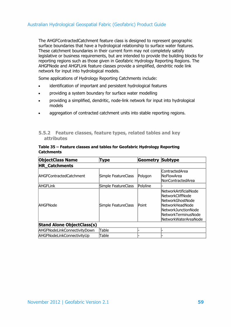
Australian Hydrological Geospatial Fabric (Geofabric) Product Guide
November 2012 | Geofabric Version 2.1 59
The AHGFContractedCatchment feature class is designed to represent geographic surface boundaries that have a hydrological relationship to surface water features. These catchment boundaries in their current form may not completely satisfy legislative or business requirements, but are intended to provide the building blocks for reporting regions such as those given in Geofabric Hydrology Reporting Regions. The AHGFNode and AHGFLink feature classes provide a simplified, dendritic node link network for input into hydrological models.
Some applications of Hydrology Reporting Catchments include:
identification of important and persistent hydrological features
providing a system boundary for surface water modelling
providing a simplified, dendritic, node-link network for input into hydrological models
aggregation of contracted catchment units into stable reporting regions.
5.5.2 Feature classes, feature types, related tables and key attributes
Table 35 – Feature classes and tables for Geofabric Hydrology Reporting
Catchments
ObjectClass Name Type Geometry Subtype
HR_Catchments
AHGFContractedCatchment Simple FeatureClass Polygon ContractedArea
NoFlowArea NonContractedArea
AHGFLink Simple FeatureClass Polyline -
AHGFNode Simple FeatureClass Point
NetworkArtificialNode NetworkCliffNode
NetworkGhostNode NetworkHeadNode
NetworkJunctionNode
NetworkTerminusNode NetworkWaterAreaNode
Stand Alone ObjectClass(s) AHGFNodeLinkConnectivityDown Table - - AHGFNodeLinkConnectivityUp Table - -
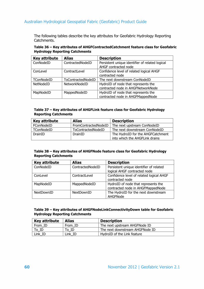
Australian Hydrological Geospatial Fabric (Geofabric) Product Guide
60 November 2012 | Geofabric Version 2.1
The following tables describe the key attributes for Geofabric Hydrology Reporting Catchments.
Table 36 – Key attributes of AHGFContractedCatchment feature class for Geofabric
Hydrology Reporting Catchments
Key attribute Alias Description ConNodeID ContractedNodeID Persistent unique identifier of related logical
AHGF contracted node
ConLevel ContractLevel Confidence level of related logical AHGF contracted node
TConNodeID ToContractedNodeID The next downstream ConNodeID
NetNodeID NetworkNodeID HydroID of node that represents the contracted node in AHGFNetworkNode
MapNodeID MappedNodeID HydroID of node that represents the
contracted node in AHGFMappedNode
Table 37 – Key attributes of AHGFLink feature class for Geofabric Hydrology
Reporting Catchments
Key attribute Alias Description FConNodeID FromContractedNodeID The next upstream ConNodeID
TConNodeID ToContractedNodeID The next downstream ConNodeID
DrainID DrainID The HydroID for the AHGFCatchment
into which the AHGFLink drains
Table 38 – Key attributes of AHGFNode feature class for Geofabric Hydrology
Reporting Catchments
Key attribute Alias Description ConNodeID ContractedNodeID Persistent unique identifier of related
logical AHGF contracted node
ConLevel ContractLevel Confidence level of related logical AHGF contracted node
MapNodeID MappedNodeID HydroID of node that represents the
contracted node in AHGFMappedNode
NextDownID NextDownID The HydroID for the next downstream
AHGFNode
Table 39 – Key attributes of AHGFNodeLinkConnectivityDown table for Geofabric
Hydrology Reporting Catchments
Key attribute Alias Description From_ID From_ID The next upstream AHGFNode ID
To_ID To_ID The next downstream AHGFNode ID
Link_ID Link_ID HydroID of the Link feature
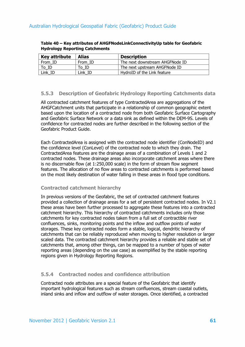
Australian Hydrological Geospatial Fabric (Geofabric) Product Guide
November 2012 | Geofabric Version 2.1 61
Table 40 – Key attributes of AHGFNodeLinkConnectivityUp table for Geofabric
Hydrology Reporting Catchments
Key attribute Alias Description From_ID From_ID The next downstream AHGFNode ID
To_ID To_ID The next upstream AHGFNode ID
Link_ID Link_ID HydroID of the Link feature
5.5.3 Description of Geofabric Hydrology Reporting Catchments data
All contracted catchment features of type ContractedArea are aggregations of the AHGFCatchment units that participate in a relationship of common geographic extent based upon the location of a contracted node from both Geofabric Surface Cartography and Geofabric Surface Network or a data sink as defined within the DEM-9S. Levels of confidence for contracted nodes are further described in the following section of the Geofabric Product Guide.
Each ContractedArea is assigned with the contracted node identifier (ConNodeID) and the confidence level (ConLevel) of the contracted node to which they drain. The ContractedArea features are the drainage areas of a combination of Levels 1 and 2 contracted nodes. These drainage areas also incorporate catchment areas where there is no discernable flow (at 1:250,000 scale) in the form of stream flow segment features. The allocation of no flow areas to contracted catchments is performed based on the most likely destination of water falling in these areas in flood type conditions.
Contracted catchment hierarchy
In previous versions of the Geofabric, the set of contracted catchment features provided a collection of drainage areas for a set of persistent contracted nodes. In V2.1 these areas have been further processed to aggregate these features into a contracted catchment hierarchy. This hierarchy of contracted catchments includes only those catchments for key contracted nodes taken from a full set of contractible river confluences, sinks, monitoring points and the inflow and outflow points of water storages. These key contracted nodes form a stable, logical, dendritic hierarchy of catchments that can be reliably reproduced when moving to higher resolution or larger scaled data. The contracted catchment hierarchy provides a reliable and stable set of catchments that, among other things, can be mapped to a number of types of water reporting areas (depending on the use case) as exemplified by the stable reporting regions given in Hydrology Reporting Regions.
5.5.4 Contracted nodes and confidence attribution
Contracted node attributes are a special feature of the Geofabric that identify important hydrological features such as stream confluences, stream coastal outlets, inland sinks and inflow and outflow of water storages. Once identified, a contracted
Australian Hydrological Geospatial Fabric (Geofabric) Product Guide
62 November 2012 | Geofabric Version 2.1
node is given a persistent identifier across the suite of products that is designed to persist through subsequent versions. As the products evolve, and the base information becomes more detailed, more contracted nodes will be added.
The business rule for the creation of a candidate contracted node is that the stream segments flowing into a node must be attributed according to a series of contracted confidence levels and be identifiable in both products (AHGFNetworkStream and AHGFMappedStream). For example, a confluence node of two or more streams that have attributes of both NAMED (i.e. the name attribute is populated) and MAJOR (a hierarchy classification of Major), and exist in both Geofabric Surface Cartography and Geofabric Surface Network, will be designated as a contracted node of the highest confidence level. Therefore, this contracted node and its Attribute ID (ConNodeID) will be highly likely to persist and have representations within both Geofabric Surface Cartography and Geofabric Surface Network, regardless of future product updates. Refer to Table 41 and Table 42 for contracted node creation rules.
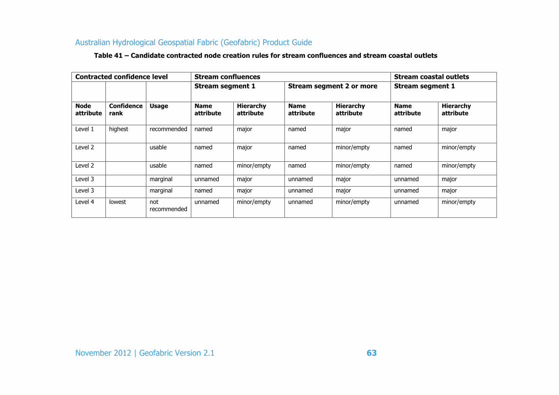
Australian Hydrological Geospatial Fabric (Geofabric) Product Guide
November 2012 | Geofabric Version 2.1 63
Table 41 – Candidate contracted node creation rules for stream confluences and stream coastal outlets
Contracted confidence level Stream confluences Stream coastal outlets
Stream segment 1 Stream segment 2 or more Stream segment 1
Node attribute
Confidence rank
Usage Name attribute
Hierarchy attribute
Name attribute
Hierarchy attribute
Name attribute
Hierarchy attribute
Level 1 highest recommended named major named major named major
Level 2 usable named major named minor/empty named minor/empty
Level 2 usable named minor/empty named minor/empty named minor/empty
Level 3 marginal unnamed major unnamed major unnamed major
Level 3 marginal named major unnamed major unnamed major
Level 4 lowest not recommended
unnamed minor/empty unnamed minor/empty unnamed minor/empty
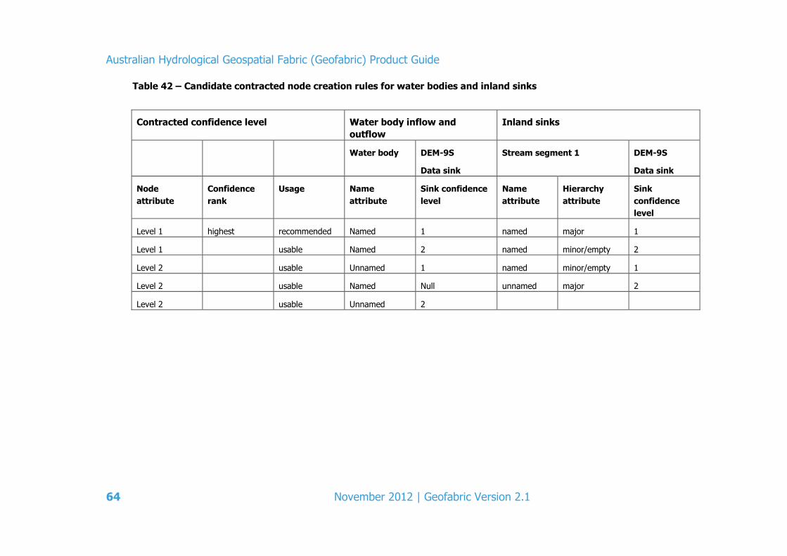
Australian Hydrological Geospatial Fabric (Geofabric) Product Guide
64 November 2012 | Geofabric Version 2.1
Table 42 – Candidate contracted node creation rules for water bodies and inland sinks
Contracted confidence level Water body inflow and
outflow
Inland sinks
Water body DEM-9S
Data sink
Stream segment 1 DEM-9S
Data sink
Node
attribute
Confidence
rank
Usage Name
attribute
Sink confidence
level
Name
attribute
Hierarchy
attribute
Sink
confidence
level
Level 1 highest recommended Named 1 named major 1
Level 1 usable Named 2 named minor/empty 2
Level 2 usable Unnamed 1 named minor/empty 1
Level 2 usable Named Null unnamed major 2
Level 2 usable Unnamed 2


Australian Hydrological Geospatial Fabric (Geofabric) Product Guide
66 November 2012 | Geofabric Version 2.1
5.6 Geofabric Hydrology Reporting Regions
Geofabric Hydrology Reporting Regions is derived from aggregations of contracted catchments from Geofabric Hydrology Reporting Catchments. This product contains two candidate reporting regions, namely AWRA Drainage Division for national scale reporting purposes and River Region for regional scale reporting purposes. More reporting regions may be added in future releases based on user requirements.
The AWRA Drainage Division is defined for the purpose of providing a stable set of reporting regions specifically for the purpose of the Bureau’s Australian Water Resources Assessment 2010 and are referred to as the 2010 Assessment Reporting Regions.
The River Regions were based on a specification developed by Bureau hydrologists involved in water resources assessment in consultation with the Geofabric team and scientists from CSIRO and ANU. These boundaries were developed for use in regional scale reporting and hydrological modelling. The River Region boundaries were not used in the Australian Water Resources Assessment 2010 but may be considered in the future as the resolution of reporting increases.
Though the Geofabric Hydrology Reporting Regions have been developed for the purposes of the Australian Water Resources Assessment, it is envisaged that these units can be used more generally as a standard for hydrological reporting at the national and regional scale, and thus replace the Australia River Basins 1997 (www.ga.gov.au/meta/ANZCW0703005427.html).
Table 43 shows the Geofabric Hydrology Reporting Regions feature class terminology and feature subtypes.
5.6.1 Understanding and using Geofabric Hydrology Reporting Regions
The purpose of Geofabric Hydrology Reporting Regions is to provide a stable set of reporting boundaries at both the national and regional scale. It contains two levels of hydrological reporting regions. The first delineates national level drainage divisions and the second delineates regional level river regions across Australia.
While the Geofabric Hydrology Reporting Regions were developed on the basis of Bureau requirements for water resources assessment, it is envisaged that these units can be more generally used as the standard for hydrological reporting at the national and regional scale and thus replace GA’s River Basins (1997).
The Reporting Region products exist as polygon feature classes and can be used for reporting hydrological phenomena within a given catchment or catchments. Alternately, the contracted catchment features can be accessed through a lookup table, namely AWRADDContractedCatchmentLookup or RRContractedCatchmentLookup tables.
Some applications for this product include:
use of the AWRADrainageDivisions for national scale hydrological reporting
use of the RiverRegions for regional scale hydrological reporting

Australian Hydrological Geospatial Fabric (Geofabric) Product Guide
November 2012 | Geofabric Version 2.1 67
aggregation of data or statistics according to hydrological significant units
presentation of information for maps which make comparisons across reporting regions. For example, a map of water availability by region
use as a boundary layer for searching and locating data of interest within a given region.
5.6.2 Feature classes, feature types, related tables and key attributes
Table 43 – Feature classes and tables for Geofabric Hydrology Reporting Regions
ObjectClass Name Type Geometry Subtype
HR_Regions AWRADrainageDivision Simple FeatureClass Polygon - RiverRegion Simple FeatureClass Polygon - Stand Alone ObjectClass(s) AWRADDContractedCatchmentLookup Table - - RRContractedCatchmentLookup Table - -
The following tables describe the key attributes for Geofabric Hydrology Reporting Regions.
Table 44 – Key attributes of AWRADrainageDivision feature class for Geofabric
Hydrology Reporting Regions
Key attribute Alias Description DivNumber DivisionNumber The number assigned to the
AWRADrainageDivision
Division Division The name assigned to the
AWRADrainageDivision
Table 45 – Key attributes of RiverRegion feature class for Geofabric Hydrology
Reporting Regions
Key attribute Alias Description Division Division The corresponding AWRADrainageDivision
name
RivRegName RiverRegionName The name assigned to the RiverRegion
Table 46 – Key attributes of AWRADDContractedCatchmentLookup table for
Geofabric Hydrology Reporting Regions
Key attribute Alias Description ConCatID ContractedCatchmentID The HydroID for a contracted
catchment
AWRADDID AWRADDID Numeric ID of the Drainage Divisions
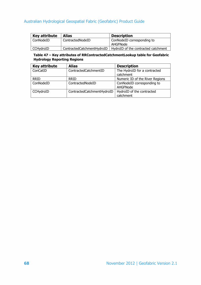
Australian Hydrological Geospatial Fabric (Geofabric) Product Guide
68 November 2012 | Geofabric Version 2.1
Key attribute Alias Description ConNodeID ContractedNodeID ConNodeID corresponding to
AHGFNode
CCHydroID ContractedCatchmentHydroID HydroID of the contracted catchment
Table 47 – Key attributes of RRContractedCatchmentLookup table for Geofabric
Hydrology Reporting Regions
Key attribute Alias Description ConCatID ContractedCatchmentID The HydroID for a contracted
catchment
RRID RRID Numeric ID of the River Regions
ConNodeID ContractedNodeID ConNodeID corresponding to AHGFNode
CCHydroID ContractedCatchmentHydroID HydroID of the contracted
catchment

Australian Hydrological Geospatial Fabric (Geofabric) Product Guide
November 2012 | Geofabric Version 2.1 69
6 Database schemas by product
Database schemas are available for each product:
Geofabric Surface Cartography
Geofabric Surface Network
Geofabric Surface Catchments
Geofabric Groundwater Cartography
Geofabric Hydrology Reporting Catchments
Geofabric Hydrology Reporting Regions.
These are available: www.bom.gov.au/water/geofabric/documentation.shtml
Australian Hydrological Geospatial Fabric (Geofabric) Product Guide
70 November 2012 | Geofabric Version 2.1
7 Data dictionaries
Data dictionaries are available for each product:
Geofabric Surface Cartography
Geofabric Surface Network
Geofabric Surface Catchments
Geofabric Groundwater Cartography
Geofabric Hydrology Reporting Catchments
Geofabric Hydrology Reporting Regions.
These are available at: www.bom.gov.au/water/geofabric/documentation.shtml
Australian Hydrological Geospatial Fabric (Geofabric) Product Guide
November 2012 | Geofabric Version 2.1 71
8 Data Product Specifications (DPS)
The Data Product Specifications are based upon the AS/NZS ISO 19131:2008 Geographic information – Data product specifications standard (AS/NZS, July 21, 2008), http://www.saiglobal.com/online/. This document provides a framework for the completion of a DPS for the geographic data product produced as part of the Geofabric project.
Data Product Specifications are available for each product:
Geofabric Surface Cartography
Geofabric Surface Network
Geofabric Surface Catchments
Geofabric Groundwater Cartography
Geofabric Hydrology Reporting Catchments
Geofabric Hydrology Reporting Regions.
These are available at: www.bom.gov.au/water/geofabric/documentation.shtml

Australian Hydrological Geospatial Fabric (Geofabric) Product Guide
72 November 2012 | Geofabric Version 2.1
References
Atkinson, R, Power, R, Lemon, D, O’Hagan, R, Dee, D & Kinny, D 2008, The Australian Hydrological Geospatial Fabric – development methodology and conceptual architecture, CSIRO Water for a Healthy Country National Research Flagship report, Australia.
Fenner School of Environment and Society, ANU and Geoscience Australia 2008, GEODATA 9 Second DEM and D8 Digital Elevation Model Version 3 and Flow Direction Grid, User Guide, Geoscience Australia, (www.ga.gov.au/image_cache/GA11644.pdf).
Geoscience Australia 1997, Australia’s River Basins 1997: GA Metadata, www.ga.gov.au/meta/ANZCW0703005427.html Horizon Systems Corporation 2008, NHDPlus Home, www.horizon-systems.com/NHDPlus/index.php
Stein, JL, Hutchinson, MF & Stein, JA 2008a, Appendix 7: “Development of a continent-wide spatial framework”, in Ecohydrological regionalisation of Australia: a tool for management and science, Innovations Project GRU36, Final Report to Land and Water Australia, BJ Pusey, MJ KennardJL Stein, JD Olden, SJ Mackay, MF Hutchinson & F Sheldon (eds).
Stein, JL & Hutchinson, MF 2008b, A review of nested catchment reference systems for Version 1.0 of the National Catchments and Reporting Units, Report to the Bureau of Meteorology Australia, Fenner School of Environment and Society, Australian National University, Australia.
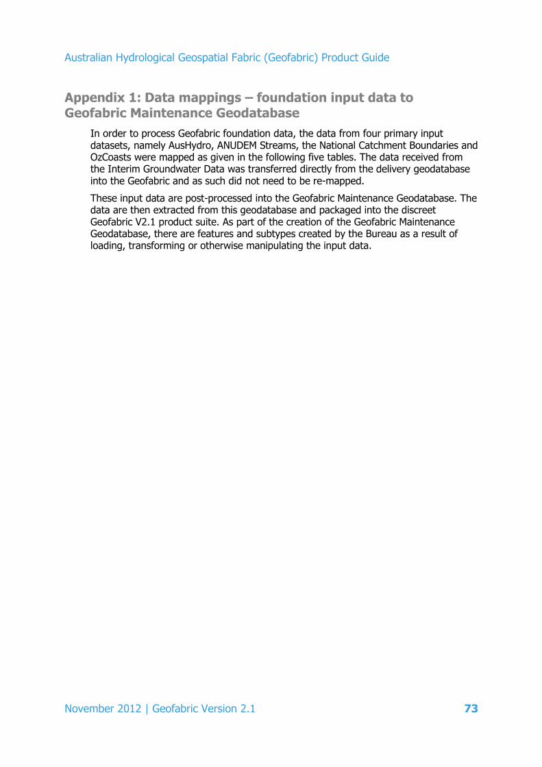
Australian Hydrological Geospatial Fabric (Geofabric) Product Guide
November 2012 | Geofabric Version 2.1 73
Appendix 1: Data mappings – foundation input data to Geofabric Maintenance Geodatabase
In order to process Geofabric foundation data, the data from four primary input datasets, namely AusHydro, ANUDEM Streams, the National Catchment Boundaries and OzCoasts were mapped as given in the following five tables. The data received from the Interim Groundwater Data was transferred directly from the delivery geodatabase into the Geofabric and as such did not need to be re-mapped.
These input data are post-processed into the Geofabric Maintenance Geodatabase. The data are then extracted from this geodatabase and packaged into the discreet Geofabric V2.1 product suite. As part of the creation of the Geofabric Maintenance Geodatabase, there are features and subtypes created by the Bureau as a result of loading, transforming or otherwise manipulating the input data.

Australian Hydrological Geospatial Fabric (Geofabric) Product Guide
74 November 2012 | Geofabric Version 2.1
Table 48 – Mapping of AusHydro data to Geofabric Maintenance Geodatabase
AusHydro Input Feature Classes
Feature Class Geometry
AusHydro Feature Class + AusHydro Subtypes (if applicable)
AGHF_Hydrography - Feature Class.Subtype
AHGF Feature Type Number
CanalAreas polygon CanalAreas. AHGFHydroArea.CanalArea 55
CanalLines line CanalLines. AHGFCanalLine 30
DamWalls line DamWalls. AHGFHydroLine.DamWall 48
Discontinuities line Discontinuities.Cliff AHGFHydroLine.CliffLine 49
Flats polygon
Flats.LandSubjectToInundation AHGFHydroArea.Flat 56
Flats.MarineSwamp AHGFHydroArea.Flat 56
Flats.SalineCoastalFlat AHGFHydroArea.Flat 56
Flats.Swamp AHGFWaterbody.Swamp 27
ForeshoreFlats polygon ForeshoreFlats. AHGFHydroArea.ForeshoreFlat 59
FrameworkBoundaries line
FrameworkBoundaries.Shoreline AHGFHydroLine.Shoreline 51
FrameworkBoundaries.Junction AHGFHydroLine.ShorelineJunction 52
FrameworkBoundaries.LimitOfData none
FrameworkBoundaries.StateBorder
Lakes polygon Lakes AHGFWaterbody.Lake 26
Levees lines Levee AHGFHydroLine.Levee 50
Locations points
Locations.Bay AHGFHydroPoint.Bay 44
Locations.Beach
none
Locations.Cape
Locations.Gorge
Locations.Mountain
Locations.Pass
Locations.RoadJunction
Locations.WaterbodyIsland
Locations.Placename
Locks points Locks AHGFStructure.Lock 33

Australian Hydrological Geospatial Fabric (Geofabric) Product Guide
November 2012 | Geofabric Version 2.1 75
AusHydro Input Feature Classes
Feature Class Geometry
AusHydro Feature Class + AusHydro Subtypes (if applicable)
AGHF_Hydrography - Feature Class.Subtype
AHGF Feature Type Number
Pipelines line
Pipelines.GasPipeline
none Pipelines.OilPipeline
Pipelines.PipelineOther
Pipelines.WaterPipeline AHGFWaterPipeline 29
PondageAreas polygon
PondageAreas.AquacultureArea AHGFHydroArea.PondageArea 57
PondageAreas.SaltEvaporator AHGFHydroArea.PondageArea 57
PondageAreas.SettlingPond AHGFHydroArea.PondageArea 57
RailwayBridgePoints points RailwayBridgePoints. AHGFStructure.Bridge 35
RailwayTunnelLines line RailwayTunnelLines. AHGFHydroLine.Tunnel 53
RapidAreas polygon RapidAreas. AHGFHydroArea.RapidArea 58
RapidLines line RapidLines. AHGFHydroLine.RapidLine 46
Reservoirs polygon Reservoirs.FloodIrrigationStorage AHGFWaterbody.Reservoir 25
Reservoirs.TownRuralStorage AHGFWaterbody.Reservoir 25
RoadCrossingPoints points RoadCrossingPoints.FordPoint AHGFStructure.Ford 36
RoadCrossingPoints.RoadBridgePoint AHGFStructure.Bridge 35
RoadTunnelLines line RoadTunnelLines. AHGFHydroLine.Tunnel 53
Seas polygon Seas AHGFSea 32
Spillways line Spillways AHGFHydroLine.Spillway 47
Springs points Spring. AHGFHydroPoint.Spring 37
WatercourseAreas polygon WatercourseAreas. AHGFHydroArea.WatercourseArea 54
WatercourseLines line
WatercourseLines.Watercourse AHGFMappedStream.MappedFlowSegment 11
WatercourseLines.Connector (Non-WaterArea) AHGFMappedStream.MappedArtificialFlowSegment 12
WatercourseLines.Connector (WaterArea) AHGFMappedStream.MappedWaterAreaSegment 13
Placeholder for new WCfeatures
line AHGFMappedStream.MappedConstructedSegment 14
WaterfallPoints points WaterfallPoints AHGFStructure.Waterfall 34
Waterholes points Waterholes AHGFHydroPoint.Waterhole 45
Australian Hydrological Geospatial Fabric (Geofabric) Product Guide
76 November 2012 | Geofabric Version 2.1
AusHydro Input Feature Classes
Feature Class Geometry
AusHydro Feature Class + AusHydro Subtypes (if applicable)
AGHF_Hydrography - Feature Class.Subtype
AHGF Feature Type Number
WaterPoints points
WaterPoints.GnammaHole AHGFHydroPoint.GnammaHole 38
WaterPoints.NativeWell AHGFHydroPoint.NativeWell 39
WaterPoints.Pool AHGFHydroPoint.Pool 40
WaterPoints.Rockhole AHGFHydroPoint.Rockhole 41
WaterPoints.Soak AHGFHydroPoint.Soak 42
WaterStoragePoints points
WaterStoragePoints.Dam AHGFDam 31
WaterStoragePoints.SwimmingPool none
WaterStoragePoints.WaterTank AHGFHydroPoint.WaterTank 43

Australian Hydrological Geospatial Fabric (Geofabric) Product Guide
November 2012 | Geofabric Version 2.1 77
Table 49 – Mapping of ANUDEM Streams to Geofabric Maintenance Geodatabase
ANUDEM Input Feature Classes
Feature Class Geometry
Feature Class Subtypes
Stream Segment Type Attribute
Water Body Segment Type Attribute
AGHF_Framework – Feature Class.Subtype
AHGF Feature Type Number
ANUDEMDerivedStreams line none
watercourse
AHGFNetworkStream.NetworkFlowSegment 1
lake connector AHGFNetworkStream.NetworkWaterAreaSegment 3
lake inlet AHGFNetworkStream.NetworkFlowSegment 1
lake outlet AHGFNetworkStream.NetworkFlowSegment 1
reservoir connector
AHGFNetworkStream.NetworkWaterAreaSegment 3
reservoir inlet AHGFNetworkStream.NetworkFlowSegment 1
reservoir outlet AHGFNetworkStream.NetworkFlowSegment 1
DEM connector
AHGFNetworkStream.NetworkArtificialFlowSegment 2
lake connector AHGFNetworkStream.NetworkWaterAreaSegment 3
lake inlet AHGFNetworkStream.NetworkArtificialFlowSegment 2
lake outlet AHGFNetworkStream.NetworkArtificialFlowSegment 2
reservoir connector
AHGFNetworkStream.NetworkWaterAreaSegment 3
reservoir inlet AHGFNetworkStream.NetworkArtificialFlowSegment 2
reservoir outlet AHGFNetworkStream.NetworkArtificialFlowSegment 2
DEM connector V1*
AHGFNetworkStream.NetworkFlowSegment 1
lake connector AHGFNetworkStream.NetworkWaterAreaSegment 3
lake inlet AHGFNetworkStream.NetworkFlowSegment 1
lake outlet AHGFNetworkStream.NetworkFlowSegment 1
reservoir connector
AHGFNetworkStream.NetworkWaterAreaSegment 3
reservoir inlet AHGFNetworkStream.NetworkFlowSegment 1
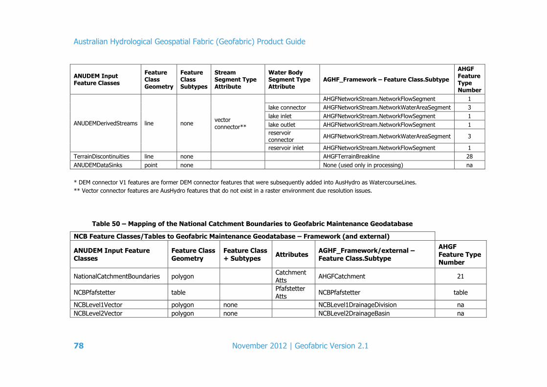
Australian Hydrological Geospatial Fabric (Geofabric) Product Guide
78 November 2012 | Geofabric Version 2.1
ANUDEM Input Feature Classes
Feature Class Geometry
Feature Class Subtypes
Stream Segment Type Attribute
Water Body Segment Type Attribute
AGHF_Framework – Feature Class.Subtype
AHGF Feature Type Number
ANUDEMDerivedStreams line none vector connector**
AHGFNetworkStream.NetworkFlowSegment 1
lake connector AHGFNetworkStream.NetworkWaterAreaSegment 3
lake inlet AHGFNetworkStream.NetworkFlowSegment 1
lake outlet AHGFNetworkStream.NetworkFlowSegment 1
reservoir connector
AHGFNetworkStream.NetworkWaterAreaSegment 3
reservoir inlet AHGFNetworkStream.NetworkFlowSegment 1
TerrainDiscontinuities line none AHGFTerrainBreakline 28
ANUDEMDataSinks point none None (used only in processing) na
* DEM connector V1 features are former DEM connector features that were subsequently added into AusHydro as WatercourseLines.
** Vector connector features are AusHydro features that do not exist in a raster environment due resolution issues.
Table 50 – Mapping of the National Catchment Boundaries to Geofabric Maintenance Geodatabase
NCB Feature Classes/Tables to Geofabric Maintenance Geodatabase – Framework (and external)
ANUDEM Input Feature
Classes
Feature Class
Geometry
Feature Class
+ Subtypes Attributes
AGHF_Framework/external –
Feature Class.Subtype
AHGF
Feature Type Number
NationalCatchmentBoundaries polygon Catchment
Atts AHGFCatchment 21
NCBPfafstetter table Pfafstetter Atts
NCBPfafstetter table
NCBLevel1Vector polygon none NCBLevel1DrainageDivision na
NCBLevel2Vector polygon none NCBLevel2DrainageBasin na

Australian Hydrological Geospatial Fabric (Geofabric) Product Guide
November 2012 | Geofabric Version 2.1 79
Table 51 – Mapping of the OzCoasts to Geofabric Maintenance Geodatabase
ANUDEM Input Feature
Classes
Feature Class
Geometry
Feature Class +
Subtypes
Hydrography – Feature
Class
AHGF Feature Type
Number
OzCoast (NSW) polygon geohab_nsw_v2 AHGFEstuary 72
OzCoast (NT) polygon geohab_nt_v2 AHGFEstuary 72
OzCoast (QLD) polygon geohab_qld_v2 AHGFEstuary 72
OzCoast (SA) polygon geohab AHGFEstuary 72
OzCoast (TAS) polygon geohab_tas AHGFEstuary 72
OzCoast (VIC) polygon geohab_vic AHGFEstuary 72
OzCoast (WA) polygon geohab_wa_v2 AHGFEstuary 72

Australian Hydrological Geospatial Fabric (Geofabric) Product Guide
80 November 2012 | Geofabric Version 2.1
Table 52 – Features created by the Bureau to augment the foundation input data in the Geofabric Maintenance
Geodatabase
Feature classes created for Geofabric Maintenance Geodatabase – Hydrography, AHGF_Framework, AHGF_Tables and Groundwater
Feature Types created by input process or owned by the Bureau
Feature Class Geometry
Hydrography – Feature Class.Subtype
AHGF_Framework – Feature Class.Subtype
Groundwater – Feature Class. Subtype
AHGF_Tables – Table Name
AHGF Feature Type Number
AtmosphericMonitoringPoint point AHGFMonitoringPoint. AtmosphericMonitoringPoint
60
SurfaceWaterMonitoringPoint point AHGFMonitoringPoint. SurfaceWaterMonitoringPoint
61
GroundwaterMonitoringPoint point AHGFMonitoringPoint. GroundwaterMonitoringPoint
62
StorageMonitoringPoint point AHGFMonitoringPoint. StorageMonitoringPoint
63
OfftakeReturnMonitoringPoint point AHGFMonitoringPoint. OfftakeReturnMonitoringPoint
64
MappedJunctionNode point AHGFMappedNode. MappedJunctionNode
14
MappedTerminusNode point AHGFMappedNode. MappedTerminusNode
15
MappedArtificialNode point AHGFMappedNode. MappedArtificialNode
16
MappedWaterAreaNode point AHGFMappedNode. MappedWaterAreaNode
17
MappedGhostNode point AHGFMappedNode. MappedGhostNode
18
MappedHeadNode point AHGFMappedNode. MappedHeadNode
19
MappedCliffNode point AHGFMappedNode. MappedCliffNode
20
NetworkTerminusNode point AHGFNetworkNode.NetworkHeadNode 4
NetworkJunctionNode point AHGFNetworkNode.NetworkJunctionNode 5
NetworkArtificialNode point AHGFNetworkNode.NetworkArtificialNode 6
NetworkWaterAreaNode point AHGFNetworkNode.NetworkWaterAreaNode 7
NetworkGhostNode point AHGFNetworkNode.NetworkGhostNode 8
NetworkHeadNode point AHGFNetworkNode.NetworkTerminusNode 9
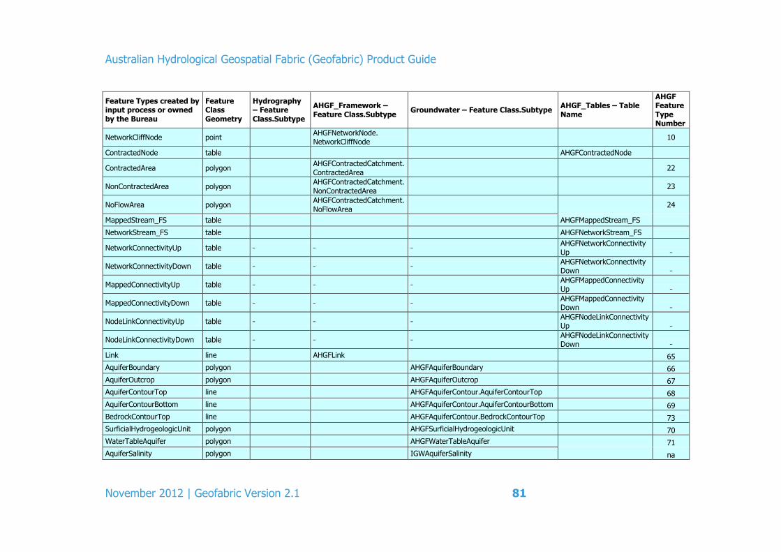
Australian Hydrological Geospatial Fabric (Geofabric) Product Guide
November 2012 | Geofabric Version 2.1 81
Feature Types created by input process or owned by the Bureau
Feature Class Geometry
Hydrography – Feature Class.Subtype
AHGF_Framework – Feature Class.Subtype
Groundwater – Feature Class.Subtype AHGF_Tables – Table Name
AHGF Feature Type Number
NetworkCliffNode point AHGFNetworkNode. NetworkCliffNode
10
ContractedNode table AHGFContractedNode
ContractedArea polygon AHGFContractedCatchment. ContractedArea
22
NonContractedArea polygon AHGFContractedCatchment. NonContractedArea
23
NoFlowArea polygon AHGFContractedCatchment. NoFlowArea
24
MappedStream_FS table AHGFMappedStream_FS
NetworkStream_FS table AHGFNetworkStream_FS
NetworkConnectivityUp table AHGFNetworkConnectivity Up
NetworkConnectivityDown table AHGFNetworkConnectivity Down
MappedConnectivityUp table AHGFMappedConnectivity Up
MappedConnectivityDown table AHGFMappedConnectivity Down
NodeLinkConnectivityUp table AHGFNodeLinkConnectivity Up
NodeLinkConnectivityDown table AHGFNodeLinkConnectivity Down
Link line AHGFLink 65
AquiferBoundary polygon AHGFAquiferBoundary 66
AquiferOutcrop polygon AHGFAquiferOutcrop 67
AquiferContourTop line AHGFAquiferContour.AquiferContourTop 68
AquiferContourBottom line AHGFAquiferContour.AquiferContourBottom 69
BedrockContourTop line AHGFAquiferContour.BedrockContourTop 73
SurficialHydrogeologicUnit polygon AHGFSurficialHydrogeologicUnit 70
WaterTableAquifer polygon AHGFWaterTableAquifer 71
AquiferSalinity polygon IGWAquiferSalinity na

Australian Hydrological Geospatial Fabric (Geofabric) Product Guide
82 November 2012 | Geofabric Version 2.1
Feature Types created by input process or owned by the Bureau
Feature Class Geometry
Hydrography – Feature Class.Subtype
AHGF_Framework – Feature Class.Subtype
Groundwater – Feature Class.Subtype AHGF_Tables – Table Name
AHGF Feature Type Number
AquiferYield polygon IGWAquiferYield na
WaterTableSalinity polygon IGWWaterTableSalinity na
WaterTableYield polygon IGWWaterTableYield na
WaterTableHydraulicConductivity polygon IGWWaterTableHydraulicConductivity na
Estuary polygon AHGFEstuary 72
Note: All of these features are created by the data input process.
Highlighted text indicates a Bureau created feature.

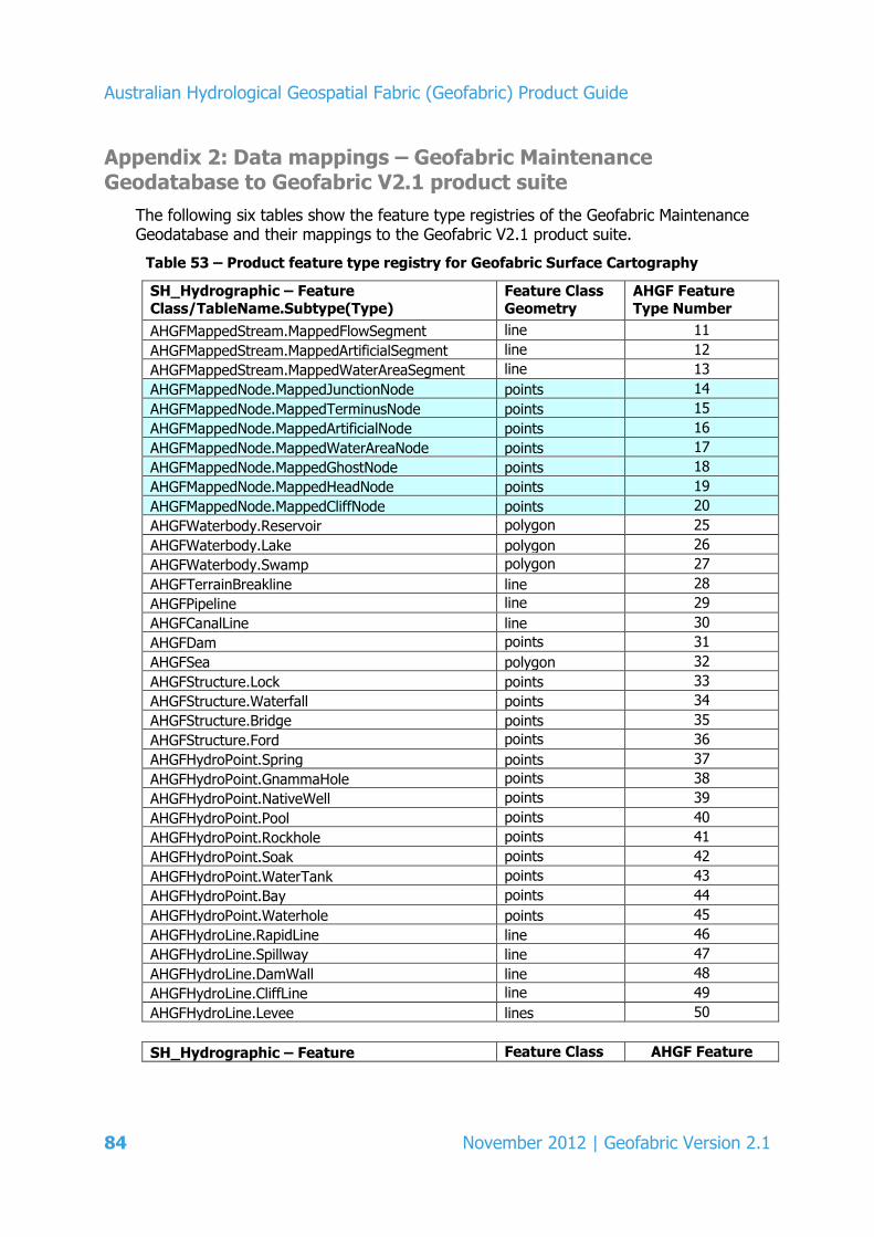
Australian Hydrological Geospatial Fabric (Geofabric) Product Guide
84 November 2012 | Geofabric Version 2.1
Appendix 2: Data mappings – Geofabric Maintenance Geodatabase to Geofabric V2.1 product suite
The following six tables show the feature type registries of the Geofabric Maintenance Geodatabase and their mappings to the Geofabric V2.1 product suite.
Table 53 – Product feature type registry for Geofabric Surface Cartography
SH_Hydrographic – Feature Class/TableName.Subtype(Type)
Feature Class Geometry
AHGF Feature Type Number
AHGFMappedStream.MappedFlowSegment line 11
AHGFMappedStream.MappedArtificialSegment line 12
AHGFMappedStream.MappedWaterAreaSegment line 13
AHGFMappedNode.MappedJunctionNode points 14
AHGFMappedNode.MappedTerminusNode points 15
AHGFMappedNode.MappedArtificialNode points 16
AHGFMappedNode.MappedWaterAreaNode points 17
AHGFMappedNode.MappedGhostNode points 18
AHGFMappedNode.MappedHeadNode points 19
AHGFMappedNode.MappedCliffNode points 20
AHGFWaterbody.Reservoir polygon 25
AHGFWaterbody.Lake polygon 26
AHGFWaterbody.Swamp polygon 27
AHGFTerrainBreakline line 28
AHGFPipeline line 29
AHGFCanalLine line 30
AHGFDam points 31
AHGFSea polygon 32
AHGFStructure.Lock points 33
AHGFStructure.Waterfall points 34
AHGFStructure.Bridge points 35
AHGFStructure.Ford points 36
AHGFHydroPoint.Spring points 37
AHGFHydroPoint.GnammaHole points 38
AHGFHydroPoint.NativeWell points 39
AHGFHydroPoint.Pool points 40
AHGFHydroPoint.Rockhole points 41
AHGFHydroPoint.Soak points 42
AHGFHydroPoint.WaterTank points 43
AHGFHydroPoint.Bay points 44
AHGFHydroPoint.Waterhole points 45
AHGFHydroLine.RapidLine line 46
AHGFHydroLine.Spillway line 47
AHGFHydroLine.DamWall line 48
AHGFHydroLine.CliffLine line 49
AHGFHydroLine.Levee lines 50
SH_Hydrographic – Feature Feature Class AHGF Feature
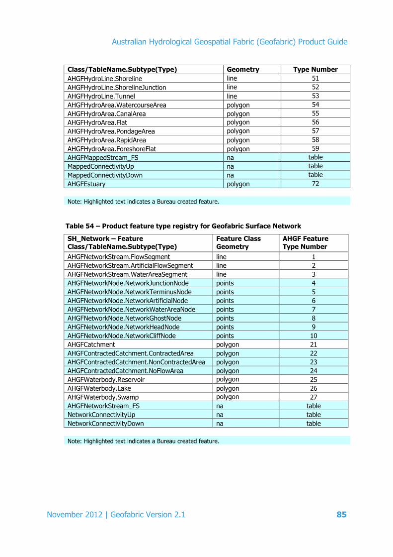
Australian Hydrological Geospatial Fabric (Geofabric) Product Guide
November 2012 | Geofabric Version 2.1 85
Class/TableName.Subtype(Type) Geometry Type Number
AHGFHydroLine.Shoreline line 51
AHGFHydroLine.ShorelineJunction line 52
AHGFHydroLine.Tunnel line 53
AHGFHydroArea.WatercourseArea polygon 54
AHGFHydroArea.CanalArea polygon 55
AHGFHydroArea.Flat polygon 56
AHGFHydroArea.PondageArea polygon 57
AHGFHydroArea.RapidArea polygon 58
AHGFHydroArea.ForeshoreFlat polygon 59
AHGFMappedStream_FS na table
MappedConnectivityUp na table
MappedConnectivityDown na table
AHGFEstuary polygon 72
Note: Highlighted text indicates a Bureau created feature.
Table 54 – Product feature type registry for Geofabric Surface Network
SH_Network – Feature
Class/TableName.Subtype(Type)
Feature Class
Geometry
AHGF Feature
Type Number
AHGFNetworkStream.FlowSegment line 1
AHGFNetworkStream.ArtificialFlowSegment line 2
AHGFNetworkStream.WaterAreaSegment line 3
AHGFNetworkNode.NetworkJunctionNode points 4
AHGFNetworkNode.NetworkTerminusNode points 5
AHGFNetworkNode.NetworkArtificialNode points 6
AHGFNetworkNode.NetworkWaterAreaNode points 7
AHGFNetworkNode.NetworkGhostNode points 8
AHGFNetworkNode.NetworkHeadNode points 9
AHGFNetworkNode.NetworkCliffNode points 10
AHGFCatchment polygon 21
AHGFContractedCatchment.ContractedArea polygon 22
AHGFContractedCatchment.NonContractedArea polygon 23
AHGFContractedCatchment.NoFlowArea polygon 24
AHGFWaterbody.Reservoir polygon 25
AHGFWaterbody.Lake polygon 26
AHGFWaterbody.Swamp polygon 27
AHGFNetworkStream_FS na table
NetworkConnectivityUp na table
NetworkConnectivityDown na table
Note: Highlighted text indicates a Bureau created feature.

Australian Hydrological Geospatial Fabric (Geofabric) Product Guide
86 November 2012 | Geofabric Version 2.1
Table 55 – Product feature type registry for Geofabric Surface Catchments
SH_Catchments – Feature Class/TableName.Subtype(Type)
Feature Class Geometry
AHGF Feature Type Number
AHGFCatchment polygon 21
NCBPfafstetter na table
NCBLevel1DrainageDivision polygon na
NCBLevel2DrainageBasin polygon na
Table 56 – Product feature type registry for Geofabric Groundwater Cartography
GW_Cartographic – Feature
Class/TableName.Subtype(Type)
Feature Class
Geometry
AHGF Feature
Type Number
AHGFAquiferBoundary polygon 66
AHGFAquiferOutcrop polygon 67
AHGFAquiferContour.AHGFAquiferContourTop line 68
AHGFAquiferContour.AquiferContourBottom line 69
AHGFAquiferContour.BedrockContourTop line 73
AHGFSurficialHydrogeologicUnit polygon 70
AHGFWaterTableAquifer polygon 71
IGWAquiferSalinity polygon na
IGWAquiferYield polygon na
IGWWaterTableSalinity polygon na
IGWWaterTableYield polygon na
IGWWaterTableHydraulicConductivity polygon na
Note: Highlighted text indicates a Bureau created feature.

Australian Hydrological Geospatial Fabric (Geofabric) Product Guide
November 2012 | Geofabric Version 2.1 87
Table 57 – Product feature type registry for Geofabric Hydrology Reporting
Catchments
HR_Catchments - Feature
Class/TableName.Subtype(Type)
Feature Class
Geometry
AHGF Feature
Type Number
AHGFNode.NetworkJunctionNode* points 4
AHGFNode.NetworkTerminusNode* points 5
AHGFNode.NetworkArtificialNode* points 6
AHGFNode.NetworkWaterAreaNode* points 7
AHGFNode.NetworkGhostNode* points 8
AHGFNode.NetworkHeadNode* points 9
AHGFNode.NetworkCliffNode* points 10
AHGFContractedCatchment.ContractedArea polygon 22
AHGFContractedCatchment.NonContractedArea polygon 23
AHGFContractedCatchment.NoFlowArea polygon 24
AHGFLink line 65
NodeLinkConnectivityUp na table
NodeLinkConnectivityDown na table
* Subset of AHGFNetworkNode features corresponding to logically contracted nodes.
Note: Highlighted text indicates a Bureau created feature.
Table 58 – Product feature type registry for Geofabric Hydrology Reporting Regions
HR_Regions - Feature Class/TableName.Subtype(Type)
Feature Class Geometry
AHGF Feature Type Number
NCBLevel1DrainageDivision polygon na
NCBLevel2DrainageBasin polygon na
AWRADrainageDivisionCatchmentLookup na table
RiverRegionCatchmentLookup na table
* Subset of AHGFNetworkNode features corresponding to logically contracted nodes.
Note: Highlighted text indicates a Bureau created feature.

Australian Hydrological Geospatial Fabric (Geofabric) Product Guide
88 November 2012 | Geofabric Version 2.1
Appendix 3: The Pfafstetter reference system and attribute descriptions for the Pfafstetter table
The Pfafstetter reference system (Verdin and Verdin 1999) is the most widely used of the hierarchical catchment reference schemes. It was adopted for the European-wide stream and catchment database (Vogt, Colombo & Bertolo 2003) following a comprehensive review of alternative coding schemes (Britton 2002). Phillips, Redfern and Bain (2002) used the Pfafstetter system to delineate nested catchment units for the trial of a new method of conservation assessment for the Burnett River catchment in Queensland. It is also the basis of the global HYDRO1k nested catchment coverage (U.S. Geological Survey 2001) and applied in both China and Austria to support hydrological modelling activities (Fürst & Horhan in press; Jia et al. 2006; Zhang et al. 2007).
The Pfafstetter system, based on concepts developed by a Brazilian engineer, Otto Pfafstetter, delineates a hierarchical, spatially nested catchment reference system. It defines and numerically codes topographically defined sub-basin units guided by the topology of the drainage network and the size of the drainage area. The system is efficient, using only the digits zero to nine for each level of subdivision, which is significantly fewer digits than other coding schemes (Verdin & Verdin 1999). Consequently, continents can be subdivided into a large number of hydrological units with relatively short and manageable identification numbers.
The codes convey useful information about topological relations in a catchment. For example, all sections of a river network either up or downstream of any feature of interest are readily inferred from the codes using simple algebraic queries.
The system delineates hydrological units that it labels as basins and inter-basins. A Pfafstetter basin is the area drained by a tributary. The area directly drained by the reach of the main stem lying between two tributaries is labelled an inter-basin. The Pfafstetter system defines the main stem as the one draining the larger area, even where this may contradict usual naming conventions. Basins and inter-basins are repeatedly subdivided into four major tributary sub-basins, coded with the even digits, and five inter-basins, coded with the odd digits, as many times as supported by the DEM. A closed basin, that is the area draining to an internal sink, is assigned a code of zero.
The Pfafstetter coding scheme restricts subdivision of a single hydrological unit to no more than nine sub-units. When applied to a continent with many thousands of drainage basins, an additional procedure for aggregating basins is needed to keep the number of units within these limits. Verdin and Verdin’s (1999) method is to treat the adjacent groups of small coastal draining basins that lie between the four largest drainage basins as coastal inter-basins. The first (Level 1) subdivision of a continent thus delineates the largest closed basin and the four largest of the coastal basins, and allocates the remaining coastal areas to coastal inter-basins.
The Pfafstetter reference system description above is an excerpt from Stein & Hutchinson (2008).
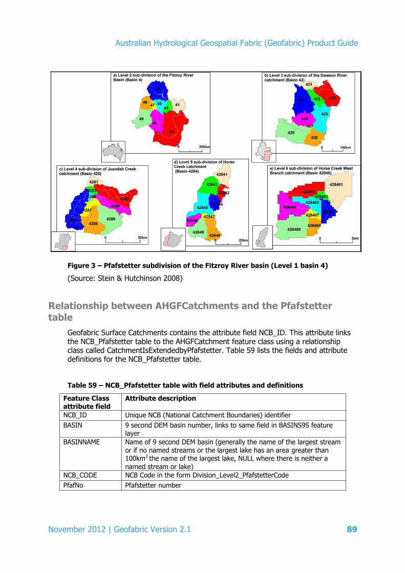
Australian Hydrological Geospatial Fabric (Geofabric) Product Guide
November 2012 | Geofabric Version 2.1 89
Figure 3 – Pfafstetter subdivision of the Fitzroy River basin (Level 1 basin 4)
(Source: Stein & Hutchinson 2008)
Relationship between AHGFCatchments and the Pfafstetter table
Geofabric Surface Catchments contains the attribute field NCB_ID. This attribute links the NCB_Pfafstetter table to the AHGFCatchment feature class using a relationship class called CatchmentIsExtendedbyPfafstetter. Table 59 lists the fields and attribute definitions for the NCB_Pfafstetter table.
Table 59 – NCB_Pfafstetter table with field attributes and definitions
Feature Class attribute field
Attribute description
NCB_ID Unique NCB (National Catchment Boundaries) identifier
BASIN 9 second DEM basin number, links to same field in BASINS9S feature layer
BASINNAME Name of 9 second DEM basin (generally the name of the largest stream
or if no named streams or the largest lake has an area greater than 100km2 the name of the largest lake, NULL where there is neither a
named stream or lake)
NCB_CODE NCB Code in the form Division_Level2_PfafstetterCode
PfafNo Pfafstetter number

Australian Hydrological Geospatial Fabric (Geofabric) Product Guide
90 November 2012 | Geofabric Version 2.1
Feature Class
attribute field
Attribute description
LEVEL1 NCB Level 1 number (= 9 second DEM Drainage Division Number)
DIVISION NCB Level 1 name (= 9 second DEM Drainage Division Name)
LEVEL2 NCB Level 2 number (internal 9 second basins merged with basins draining to the coast or into Lake Eyre, aggregated to approximate the
AWRC Basins)
LEVEL2NAME NCB Level 2 name (based on AWRC basin names)
PFAFL3 NCB Level 3 Pfafstetter Code
PFAFL4 NCB Level 4 Pfafstetter Code
PFAFL5 NCB Level 5 Pfafstetter Code
PFAFL6 NCB Level 6 Pfafstetter Code
PFAFL7 NCB Level 7 Pfafstetter Code
PFAFL8 NCB Level 8 Pfafstetter Code
PFAFL9 NCB Level 9 Pfafstetter Code
PFAFL10 NCB Level 10 Pfafstetter Code
PFAFL11 NCB Level 11 Pfafstetter Code
PFAFL12 NCB Level 12 Pfafstetter Code
PFAFL13 NCB Level 13 Pfafstetter Code
PFAFL14 NCB Level 14 Pfafstetter Code
PFAFL15 NCB Level 15 Pfafstetter Code
BasinLevel Indicates at what Pfafstetter level a basin is first separately identified
LastPfaf Last Pfafstetter level that is valid for the catchment
BasinPfaf Basin-specific Pfafstetter code
BasinD8 AWRC basin number of the AWRC basin occupying the majority of the
NCB catchment
AWRCBNUM AWRC basin number of the AWRC basin occupying the majority of the
NCB catchment unit
AWRCRNUM AWRC region number of the AWRC basin occupying the majority of the NCB catchment unit
AWRCDNUM AWRC division number of the AWRC basin occupying the majority of
the NCB catchment unit
AWRCBNAME AWRC basin name of the AWRC basin occupying the majority of the NCB catchment unit
AWRCRNAME AWRC region name of the AWRC basin occupying the majority of the
NCB catchment unit
AWRCDNAME AWRC division name of the AWRC basin occupying the majority of the NCB catchment unit
AnaBrLevel Level of sub-division at which the anabranch or anabranch downstream of the stream segment is coded separately from the main stem
MainStemUp NCB_ID of main stem stream segment upstream of an anabranch (0 if
not an anabranch offtake)
AnaBrDown NCB_ID of anabranch segment immediately downstream (0 if not an
anabranch offtake)

Australian Hydrological Geospatial Fabric (Geofabric) Product Guide
November 2012 | Geofabric Version 2.1 91
Appendix 4: Data quality information for the foundation data inputs
The quality of the spatial data and attribution is largely based upon the input data from AusHydro and ANUDEM Streams and the National Catchment Boundaries.
Additional post-processing of these feature classes creates the resulting feature classes within the Geofabric products. The data quality information cited here is from documentation that accompanies the AusHydro dataset inputs.
AusHydro and ANUDEM Streams
Lineage
It is anticipated that AusHydro will be used for a large range of applications. This lineage information is provided so that the user can understand the data sources, their history, characteristics, how they were incorporated, and the accuracy and limitations of the resultant data.
AusHydro is an amalgamation of two parent datasets to produce a single, authoritative, national stream network and a surface water feature dataset suitable for hydrological analysis at national scales. All features were populated with an AusHydro_ID field and data source code in the FeatureSource Field.
AusHydro reconciles the natural watercourse geometry from an enhanced, ANU Fenner School for Environment and Society (ANU) GEODATA 1 Surface Hydrography dataset, and the relevant attribute data from GEODATA 3. Some line work from GEODATA TOPO 250K Series 3 was also integrated. The resulting WatercourseLines feature class encapsulates the topologically correct flow paths from the ANU enhanced GEODATA 1, but with updated, quality assured and quality controlled attribute information of GEODATA 3.
The attributes from GEODATA Series 3 were transferred using spatial queries to identify common features between the two datasets. Additional semi-automated and manual editing was undertaken to ensure connectivity and continuity of attribution along the entire network. Intensive network analysis and quality assurance were also carried out to verify the accuracy of the flow directed geometric network.
The working names of the three source surface hydrography datasets used in the creation of AusHydro are:
GEODATA TOPO 250K Series 1 (GEODATA 1)
GEODADAT TOPO 250K Series 2 (GEODATA 2)
GEODATA TOPO 250K Series 3 (GEODATA 3)
GEODATA 9 Second Digital Elevation Model (DEM-9S) Version 3
GEODATA 9 Second Flow Direction Grid (D8-9S).

Australian Hydrological Geospatial Fabric (Geofabric) Product Guide
92 November 2012 | Geofabric Version 2.1
WatercourseLines feature class
The first source dataset is based on the GEODATA 1 WatercourseLines completed by GA in 1994 as a cartographic product, but whose geometry was comprehensively revised and augmented by researchers from the ANU. This was done in conjunction with development of the DEM-9S Version 3 and D8-9S.
ANU integrated data digitised from scanned national topographic 1:100,000 maps and other products to improve the representation of surface water flow, as well as updated material from GEODATA 2 (2003) and GEODATA 3 (2006). Features incorporated include: revised spot heights/elevation points, sinks, streamlines, connectors, cliff lines, water bodies, trigonometric points from the National Geodetic Database and additional elevation, streamline and sink point data digitised by the ANU from 1:100,000 source material.
Approximately 700,000 additional stream segments were captured from the 1:100,000 digital datasets and other source materials, adding significant detail and value to the national drainage network, and for this reason the ANU dataset was chosen over GEODATA 3.
DEM derived streams
The ANUDEM program generalised the input data streamlines (AusHydro – WatercourseLines) to the grid of the DEM-9S. The resulting DEM raster network consists of flow pathways defined by the national flow direction grid (D8-9S) traced from channel heads to coastal outlets (or inland sinks) to ensure full network connectivity (Stein 2006). The process turns the raster stream network into a fully connected DEM derived stream network, suitable for use in the generation of the catchment boundaries. Further information on of ANUDEM can be found on the Fenner School of Environment and Society website (http://fennerschool.anu.edu.au/research/publications/software-datasets).
The following outputs are derived from the DEM-9S using the ANUDEM program:
multi-flow direction grid (focused on representing flow directions for catchments rather than hillsides)
DEM derived streams network.
The ANUDEM D8-9S is then modified to:
add multi-directional junctions to ensure that anabranching connections are appropriately represented
manually adjust flow directions to make sure that connections between catchments that should not exist (but do as a result of resolution issues, e.g. multi-directional streams present in a single grid cell) are removed.
The ANUDEM Streams network is used to determine cells that represent stream heads. These equate to any cell containing the head of a first order stream in the ANUDEM

Australian Hydrological Geospatial Fabric (Geofabric) Product Guide
November 2012 | Geofabric Version 2.1 93
Stream network. The flow direction on the modified flow direction grid is then traced, cell by cell, until the coast or an inland sink is reached, as shown in Figure 4.
Figure 4 – Example of tracing the stream network from channel head grid cells to an
outlet on the coast
(Source: Stein 2006)
In order to distinguish the actual channelised flow network from sections and to maintain connectivity (connectors), the ANUDEM Streams are broken wherever there are disjunctions in the mapped streams as represented in the ANUDEM Streams network.
All source channels (excluding main stem, i.e. first order segments) with a contributing area of less than 1.25km2 are pruned from ANUDEM Streams network. A main stem segment is determined by traversing up the network and ascertaining which of the tributaries has the largest drainage area at each junction (i.e. confluence/bifurcation).
Finally, the remaining network is broken into segments based upon segmentation rules, which enforce breaks at heads, termini, confluences and bifurcations.
For further documentation on the DEM-9S and the D8-9S, including complete lineage and limitations information, see: ga.gov.au/topographic-mapping/digital-elevation-models/index.jsp
Australian Hydrological Geospatial Fabric (Geofabric) Product Guide
94 November 2012 | Geofabric Version 2.1
GEODATA TOPO 250K Series 3
Released by GA in 2006, the GEODATA 3 product is primarily sourced from GEODATA 2 and 1:250,000 scale map reproduction material (from the National Topographic Map Series and Defence Joint Operation Graphics). A key revision source for the data is satellite imagery taken from the SPOT Panchromatic and LANDSAT Thematic Mapper Sensors, as well as material from a variety of other respected sources. This includes naming from the Gazetteer of Australia, the authoritative source for geographic names in Australia.
More information about the sources for this data can be found in GA’s TOPO 250K Topographic Data and Map Specifications: www.ga.gov.au/mapspecs/250k100k
The following hydrographical features from the GEODATA 3 dataset were incorporated into AusHydro in their original, unmodified form: canal lines, locks, rapid lines, spillways, waterfall points, bores, canal areas, flats, lakes, pondage areas, rapid areas, reservoirs, springs, watercourse areas, waterholes, water points, marine hazard areas, marine hazard points and foreshore flats.
The AusHydro dataset also contains cultural and transport features that may intersect hydrography features: railway tunnels, rail crossings, railway bridges, road tunnels, road bridges, road crossings and water pipelines.
Since ANU watercourse augmentation did not include updating feature attribution, GEODATA 3 was primarily used for this purpose as it had the most accurate attribution on a national scale. The following attributes were transferred from GEODATA 3: name, perenniality and hierarchy.
The geometries of some watercourse features from the GEODATA 3 layer were added as well. Specifically, some watercourses that did not exist in the ANU dataset, but matched the D8-9S flow paths derived from the DEM-9S, were added manually.
Modified feature classes from GEODATA TOPO 250K Series 3
The following table lists feature classes that were derived from GEODATA 3. Please note that these feature classes are not identical to GEODATA 3 and were modified. Feature classes that were derived from, but are not identical to those in GEODATA 3, and the changes that were made to them, are as follows:

Australian Hydrological Geospatial Fabric (Geofabric) Product Guide
November 2012 | Geofabric Version 2.1 95
Table 60 – Feature classes derived from GEODATA TOPO 250K Series 3
Feature classes Source Modification
RailwayCrossingLines and
RailBridgePoints
GEODATA TOPO 250K Series 3 Feature classes were merged to form a single point feature class,
RailwayBridgePoints (AusHydro)
RailwayTunnelLines and
RailwayTunnelPoints
GEODATA TOPO 250K Series 3 Feature classes were merged to form a single point feature class,
RailwayTunnelLines (AusHydro)
RoadCrossingLines and
RoadCrossingPoints
GEODATA TOPO 250K Series 3 Feature classes were merged to form a single point feature class,
RoadCrossingPoints (AusHydro)
RoadTunnelLines and
RoadTunnelPoints
GEODATA TOPO 250K Series 3 Feature classes were merged to form a single point feature class,
RoadTunnelLines (AusHydro)
Pipelines AusHydro
Contains all features of feature subtype
WaterPipeline from the feature class
Pipelines (GEODATA 3) (features of subtype GasPipeline,
OilPipeline and PipelineOther were not included)
Locations AusHydro
Contains all features of feature subtype
Bay from the feature class Locations (GEODATA 3)
(features of subtype Beach, Cape, Gorge, Mountain, Pass, RoadJunction,
WaterbodyIsland and PlaceName were not
included)
TerrainDiscontinuities
ANU FSES modified cliffs layer
derived from the previous and
current versions of the Geodata datasets and the 9 Second DEM.
This feature class was used to create
breakpoints and segmentation rules to aid
in the creation of the WatercourseLines layer
Discontinuities AusHydro
Contains all features of feature subtypes Cliffs and Levees from GEODATA 3
(features of subtype Cutting and
Embankment were not included)

Australian Hydrological Geospatial Fabric (Geofabric) Product Guide
96 November 2012 | Geofabric Version 2.1
References (Appendices 1 to 4)
Britton, P. (2002) Review of Existing River Coding Systems For River Basin Management and Reporting (Draft). Version 1.9. European Coding Systems, WFD GIS Working Group, 29 pp. Retrieved from: http://193.178.1.168/River_Coding_Review.pdf
Fürst, J. and Horhan, T. (2009) Coding of watershed and river hierarchy to support GIS-based hydrological analyses at different scales. Computers & Geosciences 35(3): 688–696.
Jia, Y, Wang, H, Zhou, Z, Qiu, Y, Luo, X, Want, J, Uan, D & Qin, D 2006, ‘Development of the WEP-L distributed hydrological model and dynamic assessment of water resources in the Yellow River Basin’, Journal of Hydrology, vol. 331, no. 3–4, pp. 606–629.
Phillips, N, Redfern, F & Bain, J 2002, Determining the Conservation Value of Waterways – Burnett River Catchment Trial, Queensland Environmental Protection Agency, Brisbane.
Stein, JL 2006, ‘A continental landscape framework for systematic conservation planning for Australian rivers and streams’, PhD thesis, Centre for Resource and Environmental Studies, Australian National University (https://digitalcollections.anu.edu.au/handle/1885/49406).
Stein, JL & Hutchinson, MF 2008, A review of nested catchment reference systems for Version 1.0 of the National Catchments and Reporting Units, Report to the Bureau of Meteorology Australia, Fenner School of Environment and Society, Australian National University, Australia.
U.S. Geological Survey 2001, HYDRO1K Elevation Derivative Database, U.S. Geological Survey EROS Data Centre (http://eros.usgs.gov/#/Find_Data/Products_and_Data_Available/gtopo30/hydro).
Verdin, KL & Verdin, JP 1999, ‘A topological system for delineation and codification of the Earth’s river basins’, Journal of Hydrology, vol. 218, no. 1–2, pp. 1–12.
Vogt, J, Colombo, R & Bertolo, F 2003, ‘Deriving drainage networks and catchment boundaries: a new methodology combining digital elevation data and environmental characteristics’, Geomorphology, vol. 53, no. 3–4, pp. 281–298.
Australian Hydrological Geospatial Fabric (Geofabric) Product Guide
November 2012 | Geofabric Version 2.1 97
Zhang, L, Wang, Q, Dai, BX & Li, TJ 2007, ‘Classification and codification methods of stream networks in a river basin: a review’, Environmental Informatics Archives, vol. 5, pp. 364–372

Through the Water Act 2007, the Australian Government has given the Bureau of Meteorology responsibility for compiling and delivering comprehensive water information across Australia.
For more information Visit our website at www.bom.gov.au/water Send an email request to [email protected]