australia new zealand dw077-xe -...
TRANSCRIPT

Australia New Zealand
DW077-XE

3
A
10
11
2 1
9
6 7 8
5 4 3
14 13
11
12
20
19
18
21
22
18 19 201
1615 17

4
24
11
24
11
11
15
12
B2
B1

5
25
A B
6 7
4 8
27
26
C2
B4
B3
C1

6
6
3 4
7
3 4
29
2830
C5
C3
D1
C4

7
9
E2
D2
E3
E1

8
19
19
20
20
21
F
E4
G1
E5

9
10
1918
201918
21
20
I1
G2
I2
H

10
I3 I4

Director Engineering and Product DevelopmentHorst Großmann
DEWALT, Richard-Klinger-Straße 40,D-65510, Idstein, Germany
General Safety Rules
Warning! Read all instructions. Failure to follow all instructions listed below may result in electric shock, fire and/or serious injury. The term “power tool” in all of the warnings listed below refers to your mains operated (corded) power tool or battery operated (cordless) power tool.
SAVE THESE INSTRUCTIONS.
1) Work areaa) Keep work area clean and well lit. Cluttered and dark areas invite accidents.b) Do not operate power tools in explosive atmospheres, such as in the presence of Flammable liquids, gases or dust. Power tools create sparks which may ignite the dust or fumes.c) Keep children and bystanders away while operating a power tool. Distractions can cause you to lose control.
2) Electrical safetya) Power tool plugs must match the outlet. Never modify the plug in any way. Do not use any adapter plugs with earthed (grounded) power tools. Unmodified plugs and matching outlets will reduce risk of electric shock.
b) Avoid body contact with earthed or grounded sur-faces such as pipes, radiators, ranges and refrigerators. There is an increased risk of electric shock if your body is earthed or grounded.c) Do not expose power tools to rain or wet conditions. Water entering a power tool will increase the risk of elec-tric shock.d) Do not abuse the cord. Never use the cord for carry-ing, pulling or unplugging the power tool. Keep cord away from heat, oil, sharp edges or moving parts. Damaged orentangled cords increase the risk of electric shock.d) When operating a power tool outdoors, use an exten-sion cord suitable for outdoor use.Use of a cord suitable for outdoor use reduces the risk of electric shock.
3) Personal safety
a) Stay alert, watch what you are doing and use common sense when operating a power tool. Do not use a power tool while you are tired or under the influence of drugs, alcohol or medication. A moment of inattention while op-erating power tools may result in serious personal injury.
ROTARY LASER DW077-XECongratulations!You have chosen a DEWALT tool. Years ofexperience, thorough product development andinnovation make DEWALT one of the most reliablepartners for professional power tool users.
Technical dataDW077Voltage V 9.6/12/14.4/18Rotary speed min-1 0/10/80/280/800Laser class IIProtection class IP54Self-leveling range ° +/- 5Operating temperature °C -5 - +45Receptacle thread 5/8” x 11Weight (without battery pack) kg 2.5Battery pack DC9096 Battery type NiCd Voltage V 18 Weight kg 1.1 Charger DE9116Mains voltage VAC 230Approx. charging time min 60 Weight kg 0.4 The following symbols are used throughout thismanual:
Denotes risk of personal injury, loss of lifeor damage to the tool in case of nonobservanceof the instructions in thismanual.
Denotes risk of electric shock.
Fire hazard.
EC-Declaration of conformityDW077DEWALT declares that these tools have been designed in compliance with: 73/23/EEC, 98/37/EEC, 89/336/EEC, EN 60335, EN 55014-1, EN 55014-2, EN 61000-3-2, EN 61000-3-3, EN 60825-1, EN 61010-1, AS/NZS60745 & AS/NZS 3160.
For more information, please contact DEWALT at theaddress below or refer to the back of the manual.
DW077LpA(sound pressure) dB(A)* < 70Weighted RMS acceleration value m/s2 < 2.5* at the operator’s ear
TÜV RheinlandProduct and Safety GmbH (TRPS)Am Grauen Stein 1D-51105 KölnGermany Cert. No. 21103197 001
b) Use safety equipment. Always wear eye protection. Safety equipment such as dust mask, non-skid safety shoes, hard hat, or hearing protection used for appropri-ate conditions will reduce personal injuries.c) Avoid accidental starting. Ensure the switch is in the off position before plugging in. Carrying power tools with your finger on the switch or plugging in power tools that have the switch on invites accidents.d) Remove any adjusting key or wrench before turning the power tool on. A wrench or a key left attached to a ro-tating part of the power tool may result in personal injury.e) Do not overreach. Keep proper footing and balance at all times. This enables better control of the power tool in unexpected situations.f) Press properly. Do not wear loose clothing or jew-ellery. Keep your hair, clothing and gloves away from moving parts. Loose clothes, jewellery or long hair can be caught in moving parts.g) If devices are provided for the connection of dust extraction and collection facilities, ensure these are connected and properly used. Use of these devices can reduce dust related hazards.
4) Power tool use and carea) Do not force the power tool. Use the correct power tool for your application. The correct power tool will do the job better and safer at the rate for which it was designed.b) Do not use the power tool if the switch does not turn it on and off. Any power tool that cannot be controlled with the switch is dangerous and must be repaired.c) Disconnect the plug from the power source before making any adjustments, changing accessories, or stor-ing power tools. Such preventive safety measures reduce the risk of starting the power tool accidentally.d) Store idle power tools out of the reach of children and do not allow persons unfamiliar with the power tool or these instructions to operate the power tool. Power tools are dangerous in the hands of untrained users.e) Maintain power tools. Check for misalignment or binding of moving parts, breakage of parts and any other condition that may affect the power tools operation. If damaged, have the power tool repaired before use. Many accidents are caused by poorly maintained power tools.f) Keep cutting tools sharp and clean. Properly main-tained cutting tools with sharp cutting edges are lesslikely to bind and are easier to control.g) Use the power tool, accessories and tool bits etc., in accordance with these instructions and in the man-ner intended for the particular type of power tool, taking into account the working conditions and the work to be performed. Use of the power tool for operations different from those intended could result in a hazardous situation.
5) Battery tool use and carea) Ensure the switch is in the off position before inserting battery pack. Inserting the battery pack into power tools that have the switch on invites accidents.b) Recharge only with the charger specified by the manufacturer. A charger that is suitable for one typeof battery pack may create a risk of fire when used with another battery pack.c) Use power tools only with specifically designated bat-tery packs. Use of any other battery packs maycreate a risk of injury and fire.
d) When battery pack is not in use, keep it away from other metal objects like paper clips, coins, keys, nails, screws, or other small metal objects that can make a con-nection from one terminal to another. Shorting the battery terminals together may cause burns or a fire.
Additional safety instructions for rotary lasers• This laser complies with class 2 according to EN 60825-1:1994+A11. Do not replace a laser diode with a different type. If damaged, have the laser repaired by an author-ised repair agent. • Do not use the laser for any purpose other than projecting laser lines. An exposure of the eye to the beam of a class 2 laser is considered safe for a maximum of 0.25 seconds. Eyelid reflexes will normally provide adequate protection. At distances over 1 m, the laser complies with class 1 and thus is considered completely safe.• Never look into the laser beam directly and intentionally.• Do not use optical tools to view the laser beam.• Do not set up the tool at a position where the laser beam can cross any person at head height.• Do not let children come in contact with the laser.
Additional safety instructions for battery packs
Fire hazard! Avoid metal short circuiting the contacts of a detached battery pack. Do not store or carry the battery pack without the battery cap placed over the contacts.
• The battery fluid, a 25-30% solution of potassium hydroxide, can be harmful. In case of skin contact, flush immediately with water. Neutralize with a mild acid such as lemon juice or vinegar. In case of eye contact, rinse abundantly with clean water for at least 10 minutes. Consult a physician.• Never attempt to open a battery pack for any reason.
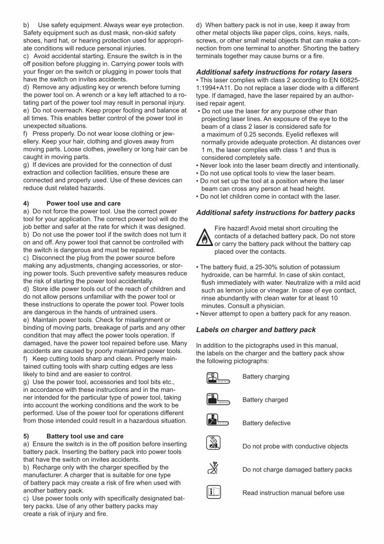
Labels on charger and battery pack
In addition to the pictographs used in this manual,the labels on the charger and the battery pack showthe following pictographs: Battery charging
Battery charged Battery defective Do not probe with conductive objects
Do not charge damaged battery packs
Read instruction manual before use
100%
100%

Use only with DEWALT battery packs, others may burst, causing personal injury and damage
Do not expose to water Have defective cords replaced immediately
Charge only between 4 °C and 40 °C
Discard the battery pack with due care for the environment
Do not incinerate the battery pack
Labels on toolThe following pictograms are shown on the tool:
Read the instruction manual before use
Laser warning
Safety warning: class 2 laser
Package contentsThe package contains:1 Rotary laser1 Detector (DE0772)1 Wall mount1 Remote control1 Target card1 Pair of glasses1 Kitbox1 Charger1 Battery pack1 Instruction manual
• Take the time to thoroughly read and understand this manual prior to operation.
Description (fig. A)The rotary laser DW077 has been designed to project laser lines to aid in professional applications.The tool can be used both inside and outside for horizon-tal (level) and vertical (plumb) alignment.
The tool can also produce a stationary laser dot that can be directed manually to establish or transfer a mark. The applications range from drop-ceiling installation and wall layout to foundation leveling and deck building.The tool accepts DEWALT battery packs of 9.6, 12,14.4 and 18 V.1 On/off switch2 Carrying handle3 Leveling knob4 Wall mount5 Rack pinion locking knob6 Wall mount clamp
7 Wall mount clamp lock8 Fitting handle9 Rack pinion wheel10 Rotary laser head11 Battery pack
ChargerYour DE9108 charger accepts DEWALT NiCd battery packs ranging from 7.2 V to 18 V.Your DE9116 charger accepts DEWALT NiCd andNiMH battery packs ranging from 7.2 V to 18 V.11 Battery pack12 Release buttons13 Charger14 Charging indicator (red)
Display15 Power indicator16 Leveling indicator (X-axis)17 Leveling indicator (Y-axis)18 Scan mode activation key19 Rotation speed setting key20 Adjustment keys left/right
Remote control18 Scan mode activation key19 Rotation speed setting key20 Adjustment keys left/right21 Adjustment keys up/down22 Manual adjustment key
Self-leveling featureThe self-leveling feature realises a quick adjustment of the rotary laser head in both level and plumb applications.Initiated as the tool is switched on, the self-levelingfeature will level the laser head in the described toolset-ups at ranges up to +/- 5°.
Electrical safetyThe electric motor has been designed for various volt-ages (see technical data). Always check that the battery pack power corresponds to the voltage on the rating plate. Also make sure that the voltage of your charger corresponds to that of your mains.
Your DEWALT charger is doubleinsulated in accordance with AS/NZS 60335.
Using an extension cableAn extension cord should not be used unless absolutely necessary. Use an approved extension cable suitable for the power input of your charger (see technical data). The minimum conductor size is 1 mm2; the maximum length is 30 m.
Assembly and adjustment• Prior to assembly and adjustment, always remove the battery pack.• Always switch off the tool before inserting or removing the battery pack.• Use only DEWALT battery packs and chargers.
+40 c+4 c

Battery pack (fig. A & B1 - B4)
Charging the battery pack (fig. A)
When charging the battery pack for the first time, orafter prolonged storage, it will only accept an 80% charge. After several charge and discharge cycles, the battery pack will attain full capacity.Always check the mains prior to charging the batterypack. If the mains is functioning but the battery packdoes not charge, take your charger to an authorisedDEWALT repair agent. Whilst charging, the charger and the battery pack may become warm to touch. This is a normal condition and does not indicate a problem.
Do not charge the battery pack at ambient temperatures < 4 °C or > 40 °C. Recommended charging temperature: approx. 24 °C.
• To charge the battery pack (11), insert it into the charger (13) as shown and plug in the charger. Be sure that the battery pack is fully seated in the charger. The red charg-ing indicator (14) will blink. After approx. 1 hour, it will stop blinking and remain on. The battery pack is now fully charged and the charger automatically switches to equal-ise mode. After approx. 4 hours, it will switch to mainte-nance charge mode. The battery pack can be removed at any time or left in the connected charger indefinitely.• The red charging indicator flashes rapidly to indicate a charging problem.Reinsert the battery pack or try a new one. If the new pack also refuses to charge, have your charger tested by an authorized DEWALT repair agent. • When plugged into power sources such as genera-tors or sources that convert DC to AC, the red charging indicator may blink twice, switch off and repeat. This indicates a temporary problem of the power source. The charger will automatically switch back to normal opera-tion. Inserting and removing the battery pack (fig. B1)• Insert the battery pack (11) into the tool until itclicks in place. • To remove the battery pack, press the two release but-tons (12) simultaneously and pull the pack out of the tool.
Battery cap (fig. B2) A protective cap is supplied to cover the contacts of a de-tached battery pack. Without the protective cap in place, loose metal objects could short circuit the contacts, caus-ing a fire hazard and damaging the battery pack.• Take off the protective cap (12) before placing the bat-tery pack (24) in the charger or tool. • Place the protective cap over the contacts immediately after removing the battery pack from the charger or tool.
Make sure the protective cap is in place before storing or carrying a detached battery pack.
Equalization mode The equalization mode helps to maintain the optimum capacity of the battery pack. It is therefore recommended to use the equalization mode weekly or every 10 charge/discharge cycles.
• Charge the battery pack as described above.• When the charging indicator stops blinking, leave the battery in the charger for approx. 4 hours.
Hot Pack DelayWhen the charger detects a battery that is hot, it automat-ically starts a Hot Pack Delay, suspending charging until the battery has cooled.After the battery has cooled, the charger automatically switches to the pack charging mode.This feature ensures maximum battery life. The redindicator (14) blinks long, then short while in the HotPack Delay mode.
Battery type (fig. B3 & B4)The tool is suitable for battery packs with differentvoltages.• To fit battery packs of 18 volt, rotate the adapter plate (25) into position A.• To fit battery packs of 9.6, 12 or 14.4 volt, rotate the adapter plate (25) into position B.Refer to the table in the back for a selection of applicable battery packs.
Setting up the tool (fig. C1 - C5)The tool facilitates various set-ups, making it usefulfor several applications.
Floor set-up (fig. C1)• Place the tool on a relatively smooth and level surface.• Adjust the tool for a level or plumb application.
Wall set-up (fig. C2 - C4)The tool has been equipped with a wall mount (4) formounting to a wall track to aid in drop ceiling installationand other specialty leveling projects (fig. C2).• Fit the tool to the wall mount by inserting the threaded pin (23) into one of the receptacles in the tool and tighten-ing the knob (8).• Turn the tool on its side with the wall mount clamp (6) in position for attachment to the wall track (fig. C3).• With the wall mount (4) facing the wall, turn the wall mount clamping lock (7) in the clockwise direction to open the clamp jaws.• Place the clamp jaws around the wall track and turn the wall mount clamping lock (7) in the anticlockwise direction to close the clamp jaws shut on the track.• Ensure that the wall mount clamping lock (7) is securely locked.
Before attaching the tool to a wall track ensurethat the track is properly secured to the wall.
• Alternatively, the tool can be hung on the wall using the mounting holes (27) in the wall mount (fig. C2).- Hold the tool at the desired position against thewall and mark the location of the two mountingholes on the wall (fig. C4).- Drill a hole at each of the marked locations (required: ø 6 mm, approx. 35 mm deep).- Insert a corresponding plug into each of the holes.- Turn a screw into each of the plugs (required: 6 x 50 mm).- Hang the tool on the screws.
• Adjust the leveling knob (3) to stabilise the tool when necessary.• Adjust the tool for a level application.
Tripod set-up (fig. C5)The tool has been equipped with a tripod receptacle for mounting to the DE0736 tripod (optional) or any other tri-pod with the required ratings stated in the technical data.• Place the tripod (28) on a relatively smooth and level surface.• Mount the tool to the tripod by turning the threaded pin (29) into the receptacle (30) in the base.• Adjust the tool for a level or plumb application.
Adjusting the tool (fig. A, D1 & D2)The tool can be adjusted for both level (fig. D1) and Plumb (fig. D2) applications.
Self-leveling feature (fig. A)• To initiate the leveling procedure, switch on the tool. The leveling procedure is indicated by the flashing of the lev-eling indicators (16 & 17) and the laser beam. Once the tool has found its level position the leveling indicators and the laser beam will stop flashing and remain on.• The leveling indicators and the laser beam repeatedly flash three times rapidly to indicate that the tool has been set up at a slope that is beyond the self-leveling range of 5°. Switch the tool off, re-adjust the tool set-up within the selfleveling range and switch the tool on again.
Level adjustment (fig. D1)• Place the tool into the required position as shown.• Switch on the tool to initiate the leveling procedure.
Plumb adjustment (fig. D2)• Place the tool into the required position as shown.• Switch on the tool to initiate the leveling procedure. As the leveling procedure for plumb applications only re-quires adjustment of the Y axis, only the corresponding leveling indicator (17) will be operational.
Manually adjusting the level position (fig. A)By using the remote control the tool can be adjustedmanually. The manual adjustment mode is particularly useful in applications with slope angles in both X and Y-axis.• To activate the manual adjustment mode press the key (22). The leveling indicators (16 & 17) go off.• Use the keys (20) to adjust the tool in the X-axis.• Use the keys (21) to adjust the tool in the Y-axis.• To discontinue the manual adjustment mode, press the key (22) again. After discontinuing the manual leveling mode the self-leveling feature automatically takes over and re-adjusts the tool to level position. The manual adjustments will be lost immediately!
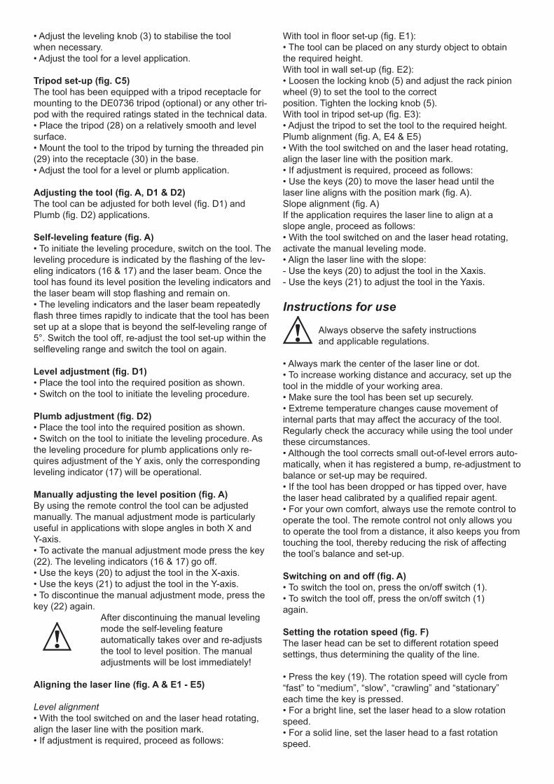
Aligning the laser line (fig. A & E1 - E5)
Level alignment• With the tool switched on and the laser head rotating, align the laser line with the position mark.• If adjustment is required, proceed as follows:
With tool in floor set-up (fig. E1):• The tool can be placed on any sturdy object to obtain the required height.With tool in wall set-up (fig. E2):• Loosen the locking knob (5) and adjust the rack pinion wheel (9) to set the tool to the correctposition. Tighten the locking knob (5). With tool in tripod set-up (fig. E3):• Adjust the tripod to set the tool to the required height.Plumb alignment (fig. A, E4 & E5)• With the tool switched on and the laser head rotating, align the laser line with the position mark.• If adjustment is required, proceed as follows:• Use the keys (20) to move the laser head until thelaser line aligns with the position mark (fig. A).Slope alignment (fig. A)If the application requires the laser line to align at aslope angle, proceed as follows:• With the tool switched on and the laser head rotating, activate the manual leveling mode.• Align the laser line with the slope:- Use the keys (20) to adjust the tool in the Xaxis.- Use the keys (21) to adjust the tool in the Yaxis.
Instructions for use
Always observe the safety instructionsand applicable regulations.
• Always mark the center of the laser line or dot.• To increase working distance and accuracy, set up the tool in the middle of your working area.• Make sure the tool has been set up securely.• Extreme temperature changes cause movement of internal parts that may affect the accuracy of the tool. Regularly check the accuracy while using the tool under these circumstances.• Although the tool corrects small out-of-level errors auto-matically, when it has registered a bump, re-adjustment to balance or set-up may be required.• If the tool has been dropped or has tipped over, have the laser head calibrated by a qualified repair agent.• For your own comfort, always use the remote control to operate the tool. The remote control not only allows you to operate the tool from a distance, it also keeps you from touching the tool, thereby reducing the risk of affecting the tool’s balance and set-up.
Switching on and off (fig. A)• To switch the tool on, press the on/off switch (1).• To switch the tool off, press the on/off switch (1)again.
Setting the rotation speed (fig. F)The laser head can be set to different rotation speedsettings, thus determining the quality of the line.
• Press the key (19). The rotation speed will cycle from “fast” to “medium”, “slow”, “crawling” and “stationary” each time the key is pressed.• For a bright line, set the laser head to a slow rotation speed.• For a solid line, set the laser head to a fast rotation speed.

Rotating the laser head (fig. G1 & G2)In the stationary position, the laser head can be moved both to the left and to the right.
Level applications:• Use the keys (20) to move the laser head into the re-quired direction.Plumb applications:• Use the keys (21) to move the laser head into the re-quired direction.
Manually rotating the laser head (fig. G2)The laser head can also be rotated manually.• Turn the laser head (10) into the required position.
Do not attempt to move the laser head while it is rotating at a preset rotation speed.
Scan mode (fig. H)The laser head can be set to different speed settings while moving back and forth, thus projecting a scanning laser line.• Press the key (18) to activate the scan mode.The scan speed starts at “fast” rate.• To set the scan speed press the key (19). The scan speed will cycle from “crawling” to “slow”, “medium” and “fast” each time the key is pressed.• Level applications:- Use the keys (20) to move the scan area into the re-quired direction.- Use the keys (21) to adjust the scan area.• Plumb applications:- Use the keys (21) to move the scan area into the re-quired direction.• Press the key (18) to discontinue the scan mode.
Out-of-level alertThe out-of-level alert activates automatically 8 seconds after the leveling procedure has been completed. Once the out-of-level alert is activated, the tool monitors its level position continuously. Depending on the registered level of deviation the tool will respond to level errors as follows: - Deviations < 2 mm over 10 m: a level error is automati-cally corrected without notifying.- Deviations 2 - 20 mm over 10 m: a level error is auto-matically corrected. The laser head temporarily stops rotating and the laser beam starts flashing to indicate that the tool re-adjusts to level position.- Deviations > 20 mm over 10 m: a level error leads to interruption of the tool’s operation. The laser head stops rotating and the laser beam goes off. A rapidly beeping audio signal is produced and the on/off indicator flashessimultaneously. To resume the operation:• Switch the tool off. Check the balance and setup and re-adjust if required before switching the tool on again.
Tool aids (fig. I1 - I4)Several aids have been supplied that might behelpful while operating the tool.
Remote control (fig. I1)The remote control allows a manual intervention of the self-leveling feature when slope adjustment is required.
The maximum slope angle corresponds to the self-lev-eling range of the tool. The remote control also allows you to activate the laser line and control the laser head from distances up to 30 m radius.
Laser enhancement glasses (fig. I2)The red lens glasses improve the visibility of the laserbeam under bright light conditions or over long distances. Providing best results indoors, the lens filters out ambient light and intensifies the projected dot or line. The glasses do not keep the laser beam from entering the eyes.Never look into the laser beam directlywith these glasses.
DE0730 Target card (fig. I3)The target card locates and marks the laser beam as the beam crosses the card, thus enhancing the visibility of the projected line. The laser beam passes through the red plastic surface and is reflected by the reflective rear side of the card. Supporting easy use during plumb and level adjustment, the card is marked with inch and metric scales, and has magnets at the top to hold it to ceiling track or steel studs.
Wall mount (fig. I4)The wall mount may also be used as a base to provide extra stability for the tool.
Optional accessoriesConsult your dealer for further information on the appro-priate accessories.These are:- DE0734 Grade rod- DE0736 Tripod
Battery packsVoltage NiCd 9.6 DE9061 12 DE9071 14.4 DE9091 18 DE9095
MaintenanceYour DEWALT Power Tool has been designed to operate over a long period of time with a minimum of mainte-nance. Continuous satisfactory operation depends upon proper tool care and regular cleaning.
Field calibration check The field calibration checks must be performed securely and accurately to make a correct diagnosis.Whenever an error is registered, have the tool calibrated by a qualified repair agent. Always have the laser head calibrated by a qualified repair agent.
Level checksThe following checks are performed to check the calibra-tion of laser head for level alignment. • Place the tool in an area at about 15 m from a vertical surface.• With the tool in a tripod set-up, adjust the tool for a level application.To perform a level check of the X-axis:

• Position the tool so that the X-axis is parallel with the vertical surface.• Switch on the tool and rotate the head until the laser dot appears on the vertical surface.• Mark the centre of the laser beam. Switch off the tool.• Switch off the tool and rotate it 180° so that the X-axis is parallel with the vertical surface the other way around.• Switch on the tool, rotate the head and once again mark the centre of the laser dot on the surface. Switch off the tool.• Measure the difference between the markings.• If the difference between the markings is 3.2 mm or less, the laser head is properly calibrated.• If the difference between the markings is more than 3.2 mm, the laser head must be calibrated.To perform a check of the Y-axis:• Position the tool so that the Y-axis is parallel with the vertical surface.• Following the same procedure as described above,mark the centre of the laser dot on the surface with the tool in this position, after which the tool is rotated 180° to mark the centre of the laser dot once again.• Measure the difference between the markings.• If the difference between the markings is 3.2 mm or less, the laser head is properly calibrated.• If the difference between the markings is more than 3.2 mm, the laser head must be calibrated.
Plumb checkThe following check is performed to check the calibration of laser head for plumb alignment.• Place the tool in an area at about 1 m from a vertical surface.• With the tool in a floor set-up, adjust the tool for a plumb application.• Mark the top and bottom of the vertical surface using a plumb bob.• Switch on the tool and align the laser beam with the lower marking.• Using the remote control, move the head until the laser beam is at the upper marking.• If the laser beam aligns with the top marking, the laser head is properly calibrated.• If the laser beam does not align with the top marking, the laser head must be calibrated.
Cleaning• Unplug the charger before cleaning the housing with a soft cloth.• Remove the battery pack before cleaning your power tool.• Keep the ventilation slots clear and regularly clean the housing with a soft cloth.• When necessary, clean the lens using a soft cloth or a cotton bud soaked in alcohol. Do not use any other clean-ing agents.
Environment
Rechargeable battery packThis long life battery pack must be recharged when it fails to produce sufficient power on jobs which were easily done before. At the end of its technical life, discard it with due care for our environment:• Run the battery pack down completely, then remove it from the tool.• NiCd and NiMH cells are recyclable. Take them to your dealer or a local recycling station. The collected battery packs will be recycled or disposed of properly.
Unwanted toolsTake your tool to an authorised DEWALT repairagent where it will be disposed of in anenvironmentally safe way.

AustraliaBlack & Decker (Australia) Pty. Ltd. Tel. 03-8720 510020 Fletcher Road, Mooroolbark, Fax 03-9727 5940Victoria, 3138
New ZealandBlack & Decker Tel. 09 579 760081 Hugo Johnston Drive Fax 09 579 8200Penrose, Auckland, New Zealand
DEWALT AFTER SALES SERVICE REPAIR AND SERVICE
All DEWALT power tools are thoroughly tested before leaving the factory. However, if the power tool needs repair, please contact your dealer or take it to your nearest DEWALT Service Centre.There is a Service Centre in every capital city.For service, repair or parts call 1800 654 155 (Aust) or09 526 2556 (NZ).
GUARANTEE
THREE YEAR LIMITED WARRANTYDEWALT will repair, without charge, any defects due to faulty ma-terials or workmanship for three years from the date of purchase. Please return the complete unit, transportation prepaid, to any DEWALT Service Centre, or any authorised service station.For warranty repair information, call 1800 654 155.This warranty does not apply to:• Accessories.• Damage caused where repairs have been made or attempted by others.• Damage due to misuse, neglect, wear and tear, alteration or modification.This warranty gives you specific legal rights and you may have other rights under the provisions of the Consumer Guarantee Act 1993 (New Zealand only), Trade Practices Act 1974 and State Legislation (Australia only).In addition to the warranty, DEWALT tools are covered by our:
FREE ONE YEAR SERVICE CONTRACTDEWALT will also maintain the tool for free at any time during the first year of purchase. This includes labour, parts and lubrication required to restore the product to sound mechanical and/or electri-cal condition. Normal wear parts are not covered in this service. Carbon brushes worn more than 50% will be replaced.
Note: 3 Year warranty is not applicable to items deemed as con-sumables. Radial arm saws are covered by a one (1) year warranty only. DEWALT reserves the right to review its warranty policyprior to launch of any new business development products.
30 DAY NO RISK SATISFACTION GUARANTEEIf you are dissatisfied with any DEWALT power tool, laser or nailer, for any reason, simply return it to the point of purchase with your sales receipt within 30 days for a replacement unit or a fullrefund.