austin-bergstrom international airport master plan update · austin-bergstrom international airport...
TRANSCRIPT

Austin-Bergstrom International Airport Master Plan Update
Chapter 4 Facility Requirements

Austin-Bergstrom International Airport Master Plan Update INTRODUCTION
In the facility requirements analyses, the capability of existing facilities to serve future demand is assessed and the needs for future facility improvements are established. The requirements analyses, which are described in this chapter, address the following facilities: airfield, terminal building, ground access, other airport, and site utility requirements. Further detail on facility requirements is found in Technical Report No. 3, Demand/Capacity Analyses and Facility Requirements.
The requirements are described for the three future planning levels (corresponding to the High Growth forecast for 2005, 2010 and 2020) described in Chapter 3. Future facility needs correspond to these demand levels, but it must be remembered that the construction of improvements will take place when needed to accommodate the demand regardless of the year in which the demand is realized.
Trigger Points
While the facility requirements presented in this report represent the extent of facilities that should be in place at a planning level, the DOA must begin the initial planning and design of a project prior to reaching the planning level demand to ensure that facilities are available when needed. The point in which a facility implementation process must be initiated is called the “trigger point.” These trigger points will allow for planning, permitting, design and construction of a project. The required lead-time will vary depending on the type of project, but in this regard the following general guidelines are provided. • New Runway – 15 years • Taxiway and Other Airfield Facilities – 3 years • Passenger Terminal Facilities (including terminal roadways) – 5 years (minimum) • Cargo Facilities – 5 years • Off-Airport Roads – 5 years • On-Airport Roads (not related to terminal) – 3 years • Parking Facilities – 3 years • Airport Support Facilities – 3 years For example, if the requirements call for 41 gates to accommodate 13 million passengers, then the planning for additional gates should commence five years prior to when traffic is expected to reach this level. Design and construction will then follow. Because of the uncertainties of forecasting future traffic it is essential that DOA monitor the traffic forecast to determine that the appropriate trigger point for initiating project planning activities has been reached.
AIRSIDE REQUIREMENTS
Airside facility requirements address the runway and taxiway system, the runway approach areas, and associated equipment such as airfield lighting and navigational aids. The analyses of airside facilities
Chapter 4
4-1 Facility Requirements

Austin-Bergstrom International Airport Master Plan Update
included an assessment of runway capacity and runway length requirement. The major findings of the airside facility requirements analyses are summarized in Table 4-1.
Table 4-1 SUMMARY OF AIRSIDE FACILITY REQUIREMENTS
Item
Planning Level 1
Planning Level 2
Planning Level 3
Third Parallel Runway No No No* R/W & T/W Shoulders Provide upon evidence of jet blast erosion Dual Parallel T/W – R/W 17L-35R X Dual Parallel T/W – R/W 17R-35L X High-speed Exit T/W (E4) – R/W 17R X Second High-speed Exit T/W – R/W 17R X High-speed Exit T/W (E3) – R/W 35L X Second High-speed Exit T/W – R/W 35L X Midfield Cross T/W Relocate if required for terminal development R/W 35L Departure Pad X Ground Runup Enclosure Contingent on level of
airline maintenance activity Install CAT III ILS – R/W 17R X
* Third runway is not required during planning period, but initial project planning may be required near the
end of the 20-year master plan period. Accelerated development of the runway may be considered.
Critical Aircraft
The planning of future airfield facilities is based on the continuation of applying the FAA standards for accommodating aircraft as large as the Boeing B747-400 (FAA airport reference code D-V). Moreover, the flexibility to accommodate potential operations of New Large Aircraft (NLA) such as the future Airbus A380 on the airfield and at cargo facilities has been incorporated in the Master Plan. The strategy for accommodating potential NLA operations is to use Runway 17R-35L as the preferred runway because it has an overall pavement width (including shoulders) of 300 feet. Therefore, in planning future airfield facilities, consideration was given to providing for NLA operations on Runway 17R-35L and associated taxiways (Taxiways C and D) if that need should occur. Some principal runway and taxiway system requirements to accommodate NLA are as follows: runway width – 200 feet; taxiway width – 100 feet; taxiway shoulder width – 40 feet; distance from taxiway centerline to object – 194 feet; and a taxiway safety area width of 262 feet. Airfield pavements would need to be stressed for aircraft weights of approximately 1.2 million pounds. These requirements relate to potential taxi routes of NLA and not the entire airfield system.
Chapter 4
4-2 Facility Requirements

Austin-Bergstrom International Airport Master Plan Update Airfield Capacity
The hourly capacities of the existing runways for VFR and IFR weather conditions have been identified as 117 and 107 operations, respectively. Table 4-2 presents the comparison of hourly demand and capacity. Based on the demand/capacity relationships shown in Table 4-2, there is adequate runway capacity to accommodate the “High Growth” forecast of peak hour operations in the long-term, as the hourly capacity exceeds the hourly demand. While the need for additional runway capacity falls beyond the master plan period, it may be required to begin the initial phase of a runway development program near the end of the planning period depending on the actual growth in traffic at ABIA. The initial phase would include preliminary planning and environmental documentation. The eventual need for additional runway capacity, albeit in the long-term, suggests that the plans for a third runway should be preserved. A Peer Review of the Master Plan Update recommended that despite the demand/capacity relationship that development of a third runway should be accelerated. This recommendation will be considered in the implementation plan.
Table 4-2
HOURLY DEMAND VERSUS CAPACITY
Item
2000
PlanningLevel 1
PlanningLevel 2
Planning Level 3
Peak Hour VFR Operations 57 71 79 96 Hourly VFR Capacity 117 117 117 117 % Capacity Utilized 49% 61% 68% 82% Peak Hour IFR Operations 38 50 57 75 Hourly IFR Capacity 107 107 107 107 % Capacity Utilized 36% 47% 53% 70%
Source: P&D Aviation analysis.
The FAA recently developed capacity benchmarks for 31 of the Nation's busiest airports to understand the relationship between airline demand and runway capacity. These benchmarks are the maximum number of flights that an airport can handle in an hour, and are similar to the hourly capacities (VFR and IFR) shown in Table 4-2. In and attempt to compare ABIA with some of the airports studied by the FAA, Table 4-3 was prepared. Table 4-3 shows five of the airports the FAA analyzed that have enplanement levels closest to those of ABIA, as opposed to many other larger hubs. The evaluation concluded that ABIA operations are significantly less than the airport capacity compared with other airports in the FAA study.
Chapter 4
4-3 Facility Requirements

Austin-Bergstrom International Airport Master Plan Update
Table 4-3 COMPARISON OF SELECTED
FAA BENCHMARKS WITH ABIA
Capacity Benchmark (Maximum Flights per Hour)
Peak Hour
Airport Optimum Rate Adverse Rate Scheduled Operations
Washington Dulles 120-121 105-117 108 Baltimore-Washington 111-120 72-75 58 San Diego 43-57 38-49 40 Tampa 110-119 80-87 49 Washington Reagan 76-80 62-66 51 ABIA 114-121 89-112 28
Source: P&D analysis of FAA data.
The FAA has used the concept of Annual Service Volume (ASV) as a reasonable estimate of an airport's annual capacity. The ASV accounts for the variations in runway use, aircraft mix and weather conditions that occur during the course of the year. It is a level of annual aircraft operations that may be used as a general reference for planning purposes, but is not a value that should be interpreted as an absolute level of annual operations that cannot be exceeded. The ASV for ABIA is estimated at 490,000 operations. Table 4-4 presents a comparison of annual operations versus annual capacity (ASV). For more information on airfield capacity please refer to Chapter 3 of Technical Report 3.
Table 4-4 ANNUAL DEMAND VERSUS CAPACITY
Item
2000 Planning Level 1
Planning Level 2
Planning Level 3
Annual Aircraft Operations 212,620 268,825 300,989 372,670 Annual Capacity 490,000 490,000 490,000 490,000 % Capacity Utilized 43% 55% 61% 76%
Source: P&D Aviation analysis.
Runway Length Important determinants of aircraft takeoff performance on a given runway include runway elevation, wind conditions, temperature, runway slope (gradient), obstacles in the takeoff path (such as high terrain or man-made objects), aircraft performance characteristics and aircraft takeoff weight (which includes the aircraft empty weight, payload and fuel, and is therefore dependent on the distance traveled). The runway length analysis considered the existing Runway 17R-35L, the longest runway at the Airport at 12,250 feet. The analysis was performed for three of the largest aircraft in the commercial aircraft fleet – the B747-400, B777-200 and Airbus A340-200. The analysis considered the existing runway conditions in terms of length, elevation, longitudinal gradient and obstacles.
Chapter 4
4-4 Facility Requirements

Austin-Bergstrom International Airport Master Plan Update
The results of this analysis showed that the present Runway 17R-35L provides excellent capability in terms of serving major international destinations. These include Tokyo, London, Sao Paulo and Rome. Therefore, further improvements in the form of a runway extension are not recommended.
Runway Width
FAA standards in AC 150/5300-13 specify a runway width of 150 feet for Airplane Design Group V aircraft (which includes the B747-400). Both runways are 150 feet wide and meet the FAA design standard. A runway width of 200 feet is required for Airplane Design Group VI, which includes NLA such as the Airbus 380. It would be relatively easy to modify Runway 17R-35L to accommodate NLA operations. In fact, the total pavement width of the west runway including shoulders is 300 feet. This exceeds the combined standards for runway and shoulder widths for ADG VI (280 feet). Therefore, the west runway can be modified to accommodate NLA operations if necessary.
Runway/Taxiway Shoulders
Paved shoulders in accordance with FAA design guidelines are currently not provided because unpaved areas adjacent to the runways and taxiways are not showing evidence of jet blast erosion. The extent of erosion in the future, if any, will depend on the amount of operations by large aircraft with engines that overhang near the edge of pavements (such as the B747). Runway and taxiway shoulders should be widened to meet FAA standards when there is evidence of jet blast erosion.
Taxiway Requirements
The ultimate build-out for the airport is planned to include a complete dual parallel taxiway system for each runway. This will reduce potential head-to-head taxi conflicts and facilitate ATC release of departures. A partial dual parallel taxiway serves Runway 17L-35R. A partial extension of the taxiway was completed in 2002. The complete extension of Taxiway A is recommended for Planning Level 1, which will complete the dual parallel taxiway on Runway 17L-35R. A dual parallel taxiway system for Runway 17R-35L will be needed in the future. It is indicated as a Planning Level 3 improvement, but the need may be earlier and will depend on the frequency of simultaneous taxiing of aircraft in opposite directions. High speed exit taxiways will be needed for the west runway. Two exit taxiways (formerly known as the Taxiway E2, E3 and E4 projects) were recently improved and involved widening of fillets for Taxiways G and T. These should serve the function of a high speed exit taxiway and accommodate a significant amount of airline arrivals. A second high speed exit taxiway for Runway 17R-35L may be considered once the effectiveness (utilization) of Taxiways G and T is known. The second exit should accommodate all aircraft that do not exit at Taxiways G or T, including wide body aircraft. The east runway is presently served by high speed exit taxiways for operations in both directions and these appear to be adequately located for present operations. A new angled exit taxiway is being constructed as part of the recent project involving the extension of Taxiway A. This exit is located
Chapter 4
4-5 Facility Requirements

Austin-Bergstrom International Airport Master Plan Update
approximately 5,000 feet from the threshold of Runway 17L. A counterpart taxiway for Runway 35R may be considered with the location determined by exit range and connection with the ultimate taxiway system. Existing cross taxiways are capable of supporting peak crossing demands during the forecast period. The location of cross taxiways is appropriate for serving the existing passenger terminal. However, various expansion concepts for the passenger terminal will likely require relocation of the cross taxiways. The ultimate location will depend on the terminal concept recommended in the Master Plan Update, and as will be seen later in this report the preferred terminal development alternative will not impact the existing cross taxiways.
Other Airfield Facilities The west runway is served by a departure pad at the north end but is not served by one on the south end. A departure pad, or widened entrance taxiway similar to those on Runway 17L-35R, is identified as a future airfield improvement for the south side of the west runway. It must be of sufficient width to permit by-pass taxi operations and should also provide accommodations for aircraft deicing. The existing “Maintenance Apron” presently functions as a penalty box as well as providing a hold apron for flights that may divert to ABIA. Future RON apron areas should accommodate these functions in the future. Aircraft run-ups are associated with general aircraft line maintenance. Depending on the extent of future airline maintenance aircraft activity at the Airport, a ground run-up enclosure (GRE), or hush house, may be considered.
Navigational Aids The Airport is presently very well served by navigational aids. Each end of the existing parallel runways is equipped for precision instrument approaches with Instrument Landing Systems (ILS). Runway 17L is equipped for Category III precision instrument approaches and all other runways accommodate Category I approaches. Upgrading of Runway 17R to Category III capability is recommended and will allow for simultaneous Category III approaches.
TERMINAL BUILDING REQUIREMENTS
The passenger terminal requirements program has been developed from the High Growth forecasts and terminal planning guidelines and factors used in the aviation industry. These requirements are minimal functional requirements, which could be exceeded during the terminal concept and design phases, due to site considerations, architectural design features and special or unique tenant needs.
Chapter 4
4-6 Facility Requirements

Austin-Bergstrom International Airport Master Plan Update Passenger Terminal Capacity
Many of the functional areas of the existing passenger terminal are near capacity based on normal passenger comfort and convenience, as summarized by the following: • Capacity of Aircraft Parking Positions (Gates). There are currently 25 aircraft gates with a total
ramp frontage of 3,400 linear feet served by 24 passenger loading bridges, each capable of accommodating a B757 aircraft, but not 24 B757s simultaneously. Seven parking positions for regional/commuter aircraft are ground-loaded and are remote to the terminal. Therefore, the capacity of existing aircraft parking positions for gates is 24 air carrier aircraft and seven regional/commuter aircraft.
• Ticketing Capacity. The existing ticketing area has about 390 frontage feet of ticket counters
containing 84 ticket agent positions. The ticketing area totals approximately 55,400 square feet. The ticketing area currently serves 1,741 peak hour enplanements on the average day of the peak month. The ticket counter capacity of the airport is estimated to be 1,600 to 2,100 peak hour enplaned passengers. The number of peak hour enplanements is currently within this range.
• Holdroom Capacity. The existing air carrier holdrooms total approximately 69,200 square feet.
The regional/commuter holdroom measures 2,600 square feet. The holdroom capacity is estimated according to the average square feet typically needed per passenger and the number of peak hour departures. The peak hour enplaning passenger capacity of the holdrooms would be about 1,600 to 1,900. The current number of peak hour enplanements falls within this range.
• Domestic Baggage Claim Capacity. The existing domestic baggage claim area has five claim
devices with a total of approximately 970 frontage feet. The baggage claim area totals about 54,300 square feet. It is estimated the domestic baggage claim capacity is 1,400 to 1,800 peak hour deplaning passengers. The number of peak hour deplaned passenger served by the baggage claim area in 2000 was within this range.
Aircraft Gate Requirements
The number of aircraft gates required in the future is estimated from the forecast of passenger aircraft departures on the average day of the peak month and the average number of departures per gate per day (gate turnover) that can reasonably be expected. Average daily air carrier departures are expected to grow from 130 in 2000 to 270 at Planning Level 3; daily regional/commuter departures are projected to grow from 8 in 2000 to 13 at Planning Level 3. Although there were no regional/commuter airlines operating at the Airport at the time of the facility requirements analysis, some are forecast. The average daily gate turnover at ABIA for air carriers is presently 5.4. This is assumed to be a reasonable limit at the present time, given that gates are dedicated to individual carriers and there is a significant gate turnover variation among the airlines. For long-range planning, a gate turnover of 5.5 is planned, on the basis that a slightly more effective gate utilization can be achieved.
Chapter 4
4-7 Facility Requirements

Austin-Bergstrom International Airport Master Plan Update
Regional/commuter gate turnover averaged 8.5 a day in 2000 for the one consolidated commuter holding area. For long-range planning, this could be expected to be 4.0 assuming each regional/commuter gate will accommodate one aircraft. This will allow each regional/commuter aircraft to be served by a loading bridge. These parameters indicate that the air carrier gate requirement will increase from 24 in 2000 to 49 at Planning Level 3. Regional/commuter carriers are expected to need 3 parking positions at Planning Level 3 (Table 4-5). Due to the trend toward larger regional/commuter aircraft and trends in boarding regional/commuter passengers, it is believed that some or all of the regional/commuter positions could be furnished with passenger loading bridges in the future.
Terminal Building Requirements Future requirements for the following program elements were estimated: ticketing area, holdrooms, airline club lounges, baggage processing, baggage claim, concessions; federal inspection services; Airport administration; public circulation and other public areas; and building services, utilities and related functions. The individual program requirements for these areas are shown in Table 4-5. The total terminal building needs are projected to increase from 674,400 square feet in the base year 2000 to about 1.0 million square feet at Planning Level 1, 1.2 million square feet at Planning Level 2 and 1.6 million square feet at Planning Level 3. The actual building areas required for any given terminal expansion configuration could vary significantly from this aggregate estimate. However, this estimate provides a reasonable projection of the potential building area needs over the forecast timeframe, and will allow for a meaningful comparison of alternative terminal concepts in the airport master plan. Terminal planning ratios can be used to evaluate whether the resulting facility needs are realistic and comparable to similar airports. Key ratios are as follows: • Aircraft gate utilization. Average gate utilization at U.S. airports varies between 200,000 to
400,000 passengers per gate per year depending on the markets served and the constraints of the facility. In 2000, the gate utilization at ABIA was about 300,000. The gate utilization projected for the terminal program ranges from about 344,000 at Planning Level 1 to 376,000 at Planning Level 3.
• Gross terminal area per gate. A measure of facility size relative to gates, the typical range at
comparable airports is from 20,000 to 35,000 square feet per gate for primarily domestic facilities. For the terminal program described here, 34,000 square feet per gate is projected for Planning Level 3, compared with 28,000 in 2000.
• Concession space as a percent of total functional terminal area. A measure of retail
opportunities in the terminal area, typical concession facilities usually range from 7 percent to 12 percent of the total functional terminal area. This is only a rough measure of concession productivity and factors such as the local market and terminal layout must be considered to insure maximizing the concession and corresponding revenue opportunities. The concessions
Chapter 4
4-8 Facility Requirements

Austin-Bergstrom International Airport Master Plan Update
percent for the proposed terminal program ranges from 8 percent at Planning Level 1 to 9 percent at Planning Level 3, compared with 5 percent in 2000.
Table 4-5 SUMMARY OF TERMINAL AREA REQUIREMENTS
FOR AUSTIN-BERGSTROM INTERNATIONAL AIRPORT
Surplus Planning Planning PlanningItem Existing 2000 (Deficiency) Level 1 Level 2 Level 3
7.7 MAP 7.7 MAP 7.7 MAP 11.0 MAP 13.2 MAP 18.4 MAP
Annual Enplaned PAX (000) 3,737 3,737 3,737 5,497 6,623 9,214Pk. Hr. Enplaned PAX (ADPM) 1,741 1,741 1,741 2,342 2,729 3,577Pk. Hr. Deplaned PAX (ADPM) 1,639 1,639 1,639 2,192 2,546 3,321Gates (Total) 25 25 0 36 41 52 Group II (Regional/Commuter) 1 1 0 3 3 3 Group III (MD-80/90, 737) 22 22 0 28 32 43 Group IV (757, 767) 2 2 0 4 (3-757) 5 (4-757) 6 (4-757)
(1-767) (1-767) (2-767)Ramp Frontage (Total - linear feet) 3,400 3,400 0 4,900 5,600 7,400Departures Roadway Curb (Eff.-linear ft.) 2,300 1,220 1,080 1,655 1,980 2,770Arrivals Roadway Curb (Eff.- linear ft.) 1,875 2,435 (560) 3,505 4,150 5,650
Terminal Area (000 sq.ft.) Ticketing/Check-in 55.4 46.6 8.8 58.8 66.7 84.2 Security Checkpoints 3 3 0 3 4 4 Airline Ticket Office (ATO) 12.4 16.7 (4.3) 22.3 26.0 34.0 Holdrooms 71.8 88.4 (16.6) 120.8 139.0 182.5 Airline Club Lounges 10.1 10.1 0.0 14.9 17.9 24.9 Outbound Baggage Area 37.8 52.2 (14.4) 70.3 81.9 107.3 Baggage Claim Area 54.3 54.1 0.2 72.3 84.0 109.6 Concessions 33.9 55.1 (21.2) 81.1 97.7 135.9 Federal Inspection Services (FIS) 16.6 16.6 0.0 16.6 29.2 35.1 Airline Ramp Services Office 21.8 21.8 0.0 32.1 38.6 53.8 Airport Admin./Operations 18.5 19.8 (1.3) 29.1 35.1 48.8 Public Circulation (Concourse) 79.1 79.4 (0.3) 110.9 127.1 166.6 Other Public Areas & Circulation 143.8 158.2 (14.4) 216.0 255.1 337.4 General Building Services & Utilities 108.7 125.4 (16.7) 171.3 202.3 267.5Total Terminal Functional Area 651.8 744.4 (92.6) 1,016.4 1,200.7 1,587.6Total Gross Terminal Area 674.4 770.2 (95.8) 1,051.6 1,242.3 1,642.7
Terminal Area Ratio AnalysesJet Gate Utilization 311,000 311,000 0 344,000 358,000 376,000Gross Term. Sq. Ft. per Air Carrier Gate 28,000 32,000 (4,000) 33,000 34,000 34,000Concessions Sq. Ft. % of Functional Area 5% 7% (2%) 8% 8% 9%
Source: P&D Aviation; Ben Lao & Associates, Inc.
Projected Requirements (Terminal Area)
Chapter 4
4-9 Facility Requirements

Austin-Bergstrom International Airport Master Plan Update
Effect of an Airline Hub
Chapter 3 briefly discussed the potential effect on the airport activity forecasts of an airline developing a connecting hub operation at ABIA. It indicated that a hub could possibly add 15 percent more passengers at Planning Level 3, and 18 percent more in the peak hour, mostly connecting passengers. Terminal programming requirements for Planning Level 3 under a Hub Scenario were considered under this assumption to test the potential effect of a hub operation on total terminal needs. Under a High Growth Hub Scenario, there would be a need for 59 gates at Planning Level 3 (56 air carrier and 3 regional/small air carrier), compared to 52 under the High Growth forecast. The total terminal building area requirement for the High Growth Hub Scenario would be about 1.9 million square feet at Planning Level 3, compared with about 1.6 million square feet under the High Growth forecast. Most of the additional terminal area would be in holdrooms, outbound and inbound baggage areas, concessions, and public circulation in concourses. Ticket counter and to some extent baggage claim areas would be affected less by the hub scenario, because the increase in passengers would primarily be connecting passengers rather than origin/destination passengers. However, a hub scenario may stimulate some additional origin/destination activity, which would necessitate additional parking and curbside requirements.
GROUND ACCESS REQUIREMENTS
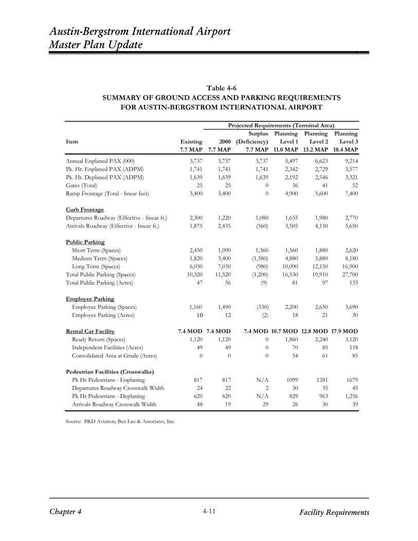
Ground access facility requirements were estimated for the following components of the surface transportation system: on-airport roadway system and intersections, passenger terminal curbside, public parking, employee parking, rental car facilities, and pedestrian facilities. Table 4-6 summarizes the facility requirements for the ground access and parking elements.
On-Airport Roadway System Requirements The on-airport roadway system was analyzed using P&D Aviation’s proprietary software called Airport IMPAX Model (AIM). The AIM model was first calibrated to represent existing conditions. The calibrated model was then used to predict future roadway conditions under varying air passenger levels and roadway network assumptions. Future roadway deficiencies and requirements were identified based on the AIM model outputs. Roadway sections and intersections were evaluated using the Level of Service (LOS) concept. The Level of Service (LOS) concept was developed to evaluate the operating conditions of different components of a transportation circulation system. The Highway Capacity Manual (HCM)1 defines LOS as a qualitative measure which describes operational conditions within a traffic stream, generally
1 Transportation Research Board, Highway Capacity Manual, Special Report 209, 2000.
Chapter 4
4-10 Facility Requirements
Austin-Bergstrom International Airport Master Plan Update
Table 4-6 SUMMARY OF GROUND ACCESS AND PARKING REQUIREMENTS
FOR AUSTIN-BERGSTROM INTERNATIONAL AIRPORT
Surplus Planning Planning PlanningItem Existing 2000 (Deficiency) Level 1 Level 2 Level 3
7.7 MAP 7.7 MAP 7.7 MAP 11.0 MAP 13.2 MAP 18.4 MAP
Annual Enplaned PAX (000) 3,737 3,737 3,737 5,497 6,623 9,214Pk. Hr. Enplaned PAX (ADPM) 1,741 1,741 1,741 2,342 2,729 3,577Pk. Hr. Deplaned PAX (ADPM) 1,639 1,639 1,639 2,192 2,546 3,321Gates (Total) 25 25 0 36 41 52Ramp Frontage (Total - linear feet) 3,400 3,400 0 4,900 5,600 7,400
Curb Frontage Departures Roadway (Effective - linear ft.) 2,300 1,220 1,080 1,655 1,980 2,770Arrivals Roadway (Effective - linear ft.) 1,875 2,435 (560) 3,505 4,150 5,650
Public Parking Short Term (Spaces) 2,450 1,090 1,360 1,560 1,880 2,620 Medium Term (Spaces) 1,820 3,400 (1,580) 4,880 5,880 8,180 Long Term (Spaces) 6,050 7,030 (980) 10,090 12,150 16,900Total Public Parking (Spaces) 10,320 11,520 (1,200) 16,530 19,910 27,700Total Public Parking (Acres) 47 56 (9) 81 97 135
Employee Parking Employee Parking (Spaces) 1,160 1,490 (330) 2,200 2,650 3,690 Employee Parking (Acres) 10 12 (2) 18 21 30
Rental Car Facility 7.4 MOD 7.4 MOD 7.4 MOD 10.7 MOD 12.8 MOD 17.9 MOD Ready Return (Spaces) 1,120 1,120 0 1,860 2,240 3,120 Independent Facilities (Acres) 49 49 0 70 85 118 Consolidated Area at Grade (Acres) 0 0 0 54 61 85
Pedestrian Facilities (Crosswalks) Pk Hr Pedestrians - Enplaning 817 817 N/A 1099 1281 1679 Departures Roadway Crosswalk Width 24 22 2 30 35 45 Pk Hr Pedestrians - Deplaning 620 620 N/A 829 963 1,256 Arrivals Roadway Crosswalk Width 48 19 29 26 30 39
Source: P&D Aviation; Ben Lao & Associates, Inc.
Projected Requirements (Terminal Area)
Chapter 4
4-11 Facility Requirements

Austin-Bergstrom International Airport Master Plan Update
in terms of such factors as speed and travel time, freedom to maneuver, traffic interruptions, comfort and convenience. LOS is rated from A to F, with LOS A representing the best operating conditions and LOS F representing the worst. This analysis identified 19 critical airport roadway sections, having insufficient capacity to operate effectively to Planning Level 3. Roadway sections with LOS E (approaching capacity) or F (exceeds capacity) were considered critical. All of these sections would operate at LOS D or better with the addition of one lane each in the critical direction. Refer to Chapter 5 of Technical Report 3 for details.
Several intersections were also identified as having insufficient capacity to operate to Planning Level 3. Improvements such as adding left turn lanes, right turn lanes, through lanes, or traffic signals could improve these intersections to an acceptable LOS. Traffic analysis indicated unsatisfactory levels of service at the SH 71/Presidential Boulevard interchange. The traffic volumes by Planning Level 2 (13.2 MAP) for the interchange is projected to be 21,800 daily vehicles with approximately 1,140 vehicles during the AM peak hour and 2,243 vehicles during the PM peak hour. This results in an unacceptable Level of Service “E”, which can be reduced to a Level of Service “C” if a two lane flyover is constructed. The following tabulation summarizes the daily and peak hour traffic volumes for this key intersection for existing conditions and Planning Levels 2 and 3.
Condition MAP AM Peak PM Peak Average Daily Trips
Northbound Presidential to westbound SH 71 Existing 7.7 MAP 296 vehicles
LOS “C”* 829 vehicles LOS “C”*
10,100
Planning Level 2 13.2 MAP 1,140 vehicles LOS “E”* LOS “C”**
2,243 vehicles LOS “F”* LOS “C”**
21,800
Planning Level 3 18.4 MAP 1,606 vehicles LOS “F”* LOS “D”**
3,158 vehicles LOS “F”* LOS “D”**
30,800
* Level of Service without flyover. ** Level of Service with flyover.
Note: By removing the northbound Presidential to westbound SH 71 traffic from the northbound Presidential to eastbound SH 71 intersection, the Level of Service drops from level “F” to “D”.
Data for the intersection of SH 71/Spirit of Texas is also presented below. This data includes average delay and level of service for the intersection.
Chapter 4
4-12 Facility Requirements

Austin-Bergstrom International Airport Master Plan Update
Condition MAP AM Peak PM Peak
Spirit of Texas Drive/SH 71 Westbound Ramps Existing 7.7 MAP 14.9 sec/veh delay
LOS “B” 18.9 sec/veh delay
LOS “B” Planning Level 2 13.2 MAP 33.3 sec/veh delay
LOS “D” 27.2 sec/veh delay
LOS “C” Planning Level 3 18.4 MAP 137.2 sec/veh delay
LOS “F” 37.7 sec/veh delay
LOS “D” (with added WB lane) (32.0 sec/veh delay)
(LOS “C”) (26.5 sec/veh delay)
(LOS “C”) Spirit of Texas Drive/SH 71 Eastbound Ramps
Existing 7.7 MAP 25.0 sec/veh delay LOS “C”
25.1 sec/veh delay LOS “C”
Planning Level 2 13.2 MAP 32.5 sec/veh delay LOS “C”
25.1 sec/veh delay LOS “C”
Planning Level 3 18.4 MAP 28.6 sec/veh delay LOS “C”
27.6 sec/veh delay LOS “C”
Passenger Terminal Curbside Requirements The existing curb frontage on the Departures Roadway is adequate for current operations. In Planning Level 1, while the existing frontage could accommodate the overall curb frontage requirements on the Departures Roadway, the private auto/taxi curb lanes will be inadequate by approximately 375 feet. This shortfall could be reduced to approximately 150 feet by relocating the charter bus drop off area (currently on the north end of the private auto curb) to the median curb. The remaining shortfall could, as an option, be provided within the existing garage where a pick-up/drop-off area is currently provided adjacent to the garage stairs. In Planning Level 2, the existing curb frontage for private auto/taxi drop off will be inadequate by approximately 650 feet. This shortfall will approximately double to 1,325 feet in Planning Level 3. The existing curb frontage on the Arrivals Roadway is currently inadequate by 560 feet for peak day peak hour operations during the peak month. This shortfall will increase to 1,630 feet in Planning Level 1, 2,275 in Planning Level 2, and 3,775 in Planning Level 3. The curb frontage requirements for taxis, courtesy (hotel) shuttles, for-hire shuttles, and charter/tour bus should be viewed in conjunction with the Ground Transportation Staging Area (GTSA), which operates as an extension of the terminal curbside areas for those vehicles. Currently, the GTSA provides queuing spaces of approximately 2,280 feet for taxis, 700 feet for shuttles, and 600 feet for buses. The GTSA was observed to be approximately 60 percent occupied during the airport peak hour. When added to the existing curb spaces allocated for these vehicles on the Arrivals Roadway, the resulting curb frontage will be able to accommodate projected requirements for these vehicles until Planning Level 3.
Chapter 4
4-13 Facility Requirements

Austin-Bergstrom International Airport Master Plan Update Public Parking Requirements
Parking requirements for short term (less than one day), medium term (1 to 3 days) and long term (more than 3 days) were estimated for the peak month of parking activity. Parking requirement estimates accounted for the projected volume of transactions by lot, the peaking characteristics during the week, parking duration by lot, and an adjustment for reserve capacity. The following discussion reflects Lot G as employee parking. The use of Lot G for employee parking occurred after the analysis of original parking requirements was completed and therefore the identification of deficiencies contained herein is current. Concept planning will be based on future requirements. In Planning Level 1, the overall parking requirements is approximately 16,530 spaces, resulting in a shortfall of approximately 6,210 spaces. All 1,560 short term parking space requirements could be accommodated within the existing garage. Approximately 4,880 spaces will be required for medium term parking. Lot A currently provides approximately 1,820 medium term parking spaces. Thus, there will be a shortfall of approximately 3,060 medium term parking spaces. The medium term parking requirements could be accommodated by constructing a new three-level parking structure over Lot A. With an estimated long term parking requirement of approximately 10,090 spaces, there will be a shortfall of approximately 4,040 long term parking spaces, which will require construction of approximately 32 acres of new long term parking. In Planning Level 2, the overall parking requirement is approximately 19,910 spaces, resulting in a shortfall of approximately 9,590 spaces. All 1,880 short term parking space requirements could be accommodated within the existing garage. Approximately 5,880 spaces will be required for medium term parking. This could be accommodated within a new three-level structure over Lot A as well as using available spaces in the existing garage. With an estimated long term parking requirement of approximately 12,150 spaces, there will be a shortfall of approximately 6,100 long term parking spaces in Planning Level 2, which will require construction of approximately 49 acres of new long term parking facility. In Planning Level 3, the overall parking requirement will increase to 27,700 spaces, resulting in a shortfall of approximately 17,380 spaces. The 2,620 short term parking space requirements will not be completely accommodated within the existing garage, resulting in a shortfall of 170 short term spaces. Converting the third floor of the existing garage to public parking will take up the deficit in short term parking, and provide approximately 1,050 medium term spaces. Constructing a three-level structure on Lot A will provide approximately 5,460 medium term parking spaces. These improvements will reduce the medium term shortfall to approximately 1,670 spaces, which will require an additional (fourth) level of structured parking. In Planning Level 3, long term parking will have a shortfall of approximately 10,850 spaces, requiring approximately 87 acres of new long term parking areas to be developed. As shown in Chapter 2, there are approximately 4,450 auto parking spaces provided off-site at various private parking lots. Since these off-airport facilities are market driven (and beyond the control of airport management) they have not been accounted for in the facility requirements analysis. The Master Plan Update therefore provides a conservative estimate of parking requirements
Chapter 4
4-14 Facility Requirements

Austin-Bergstrom International Airport Master Plan Update
and this approach will provide the greatest footprint for future parking facilities. However, the consideration of off-site parking offers options with respect to providing parking facilities on-airport. For example, the development of additional structural parking may be deferred if off-site facilities are shown to satisfy demand. Table 4-7 summarizes the public parking requirements considering off-site parking facilities. As seen, when off-site parking is taken into account the shortfalls in future planning levels are reduced. For example, in Planning Level 3 there is a shortfall of 12,925 spaces (compared to 17,380 if off-site parking is not considered).
Table 4-7 SUMMARY OF PUBLIC PARKING REQUIREMENTS
CONSIDERING OFF-SITE PARKING FACILITIES
Planning Planning PlanningItem 2000 Level 1 Level 2 Level 3
7.7 MAP 11.0 MAP 13.2 MAP 18.4 MAP
Required Public Parking Spaces 11,520 16,530 19,910 27,700 Existing ABIA Public Parking Spaces 10,320 10,320 10,320 10,320 Existing Private Parking (off-site) Parking Express 1,500 1,500 1,500 1,500 Airport Fast Park 2,500 2,500 2,500 2,500 ACE Airport Valet Parking 75 75 75 75 ABI Park & Ride 380 380 380 380 Total Existing Off-Site Parking 4,455 4,455 4,455 4,455 Existing Public Parking (ABIA+off site) 14,775 14,775 14,775 14,775 Surplus (Deficiency) 3,255 (1,755) (5,135) (12,925)
Employee Parking Requirements Employee parking requirements at ABIA were estimated based on 400 spaces per million enplanements. This ratio was set higher than the existing ratio, due to the existing parking shortall. ABIA requires approximately 1,040 additional employee parking spaces in Planning Level 1, 1,490 additional spaces in Planning Level 2, and 2,530 additional spaces in Planning Level 3. Approximately 30 acres should be reserved for employee parking in Planning Level 3.
Chapter 4
4-15 Facility Requirements
Austin-Bergstrom International Airport Master Plan Update Rental Car Facility Requirements
Rental car requirements were estimated in terms of the number of ready/return (R/R) spaces as well as the total acreage (including R/R, storage and service areas). ABIA would need to provide approximately 1,860 R/R spaces in Planning Level 1, 2,240 spaces in Planning Level 2, and 3,120 spaces in Planning Level 3. Under independent rental car operations, ABIA would require approximately 118 acres (including R/R, storage and service areas) in Planning Level 3. A consolidated rental car facility would reduce the required space to approximately 85 acres.
Pedestrian Facility Requirements
The four existing crosswalks on the Arrivals Roadway will be adequate until Planning Level 3. The two pedestrian crosswalks on the Departures Roadway will not be adequate in Planning Level 1. A third crosswalk will accommodate projected demand until Planning Level 2. In Planning Level 3, two additional crosswalks (for a total of four) will be required on the Departures Roadway. Field observations showed that while pedestrian crosswalks currently operate at satisfactory conditions, the uncoordinated stoppage of vehicular traffic at the crosswalks (particularly on the Arrivals Roadway), contribute to traffic congestion during the peak hours. The existing pedestrian volumes warrant installation of traffic signals at all crosswalks. An option would be to construct overhead pedestrian crosswalks on the Arrivals Roadway to relieve traffic congestion.
OTHER AIRPORT REQUIREMENTS
Requirements to serve airport demand to Planning Level 3 were also estimated for the following airport facilities: air cargo; airline support requirements such as aircraft maintenance, GSE, and flight kitchens; airport support requirements such as airport maintenance, fuel storage and aircraft rescue and fire-fighting facilities; general aviation facilities; other aviation facilities such as the military, State Aircraft Pooling Board, and FAA facilities; and non-aviation facilities. These facility requirements have been developed from the High Growth forecast of ABIA demand as well as needs expressed by airport tenants and operators of the facilities.
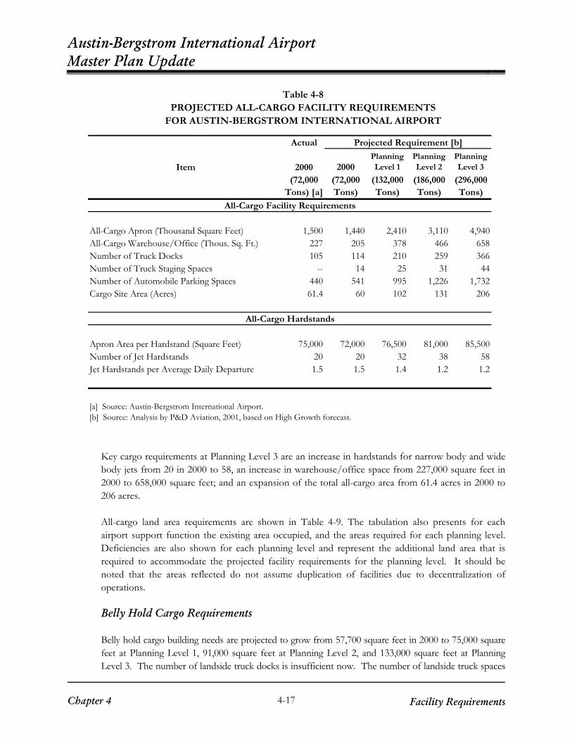
Air Cargo Requirements All-Cargo Requirements Air cargo facilities serving all-cargo flights are estimated for the following components for Planning Level 3: All-cargo apron, Warehouse/office space, Truck docks and truck staging area, Automobile parking spaces, Number of hardstands, and Total site area. The all-cargo facility requirements are summarized in Table 4-8.
Chapter 4
4-16 Facility Requirements
Austin-Bergstrom International Airport Master Plan Update
Table 4-8 PROJECTED ALL-CARGO FACILITY REQUIREMENTS
FOR AUSTIN-BERGSTROM INTERNATIONAL AIRPORT
Actual Projected Requirement [b]
Item 2000 2000Planning Level 1
Planning Level 2
Planning Level 3
(72,000 (72,000 (132,000 (186,000 (296,000Tons) [a] Tons) Tons) Tons) Tons)
All-Cargo Facility Requirements
All-Cargo Apron (Thousand Square Feet) 1,500 1,440 2,410 3,110 4,940All-Cargo Warehouse/Office (Thous. Sq. Ft.) 227 205 378 466 658Number of Truck Docks 105 114 210 259 366Number of Truck Staging Spaces -- 14 25 31 44Number of Automobile Parking Spaces 440 541 995 1,226 1,732Cargo Site Area (Acres) 61.4 60 102 131 206
All-Cargo Hardstands
Apron Area per Hardstand (Square Feet) 75,000 72,000 76,500 81,000 85,500Number of Jet Hardstands 20 20 32 38 58Jet Hardstands per Average Daily Departure 1.5 1.5 1.4 1.2 1.2
[a] Source: Austin-Bergstrom International Airport.[b] Source: Analysis by P&D Aviation, 2001, based on High Growth forecast.
Key cargo requirements at Planning Level 3 are an increase in hardstands for narrow body and wide body jets from 20 in 2000 to 58, an increase in warehouse/office space from 227,000 square feet in 2000 to 658,000 square feet; and an expansion of the total all-cargo area from 61.4 acres in 2000 to 206 acres. All-cargo land area requirements are shown in Table 4-9. The tabulation also presents for each airport support function the existing area occupied, and the areas required for each planning level. Deficiencies are also shown for each planning level and represent the additional land area that is required to accommodate the projected facility requirements for the planning level. It should be noted that the areas reflected do not assume duplication of facilities due to decentralization of operations. Belly Hold Cargo Requirements Belly hold cargo building needs are projected to grow from 57,700 square feet in 2000 to 75,000 square feet at Planning Level 1, 91,000 square feet at Planning Level 2, and 133,000 square feet at Planning Level 3. The number of landside truck docks is insufficient now. The number of landside truck spaces
Chapter 4
4-17 Facility Requirements

Austin-Bergstrom International Airport Master Plan Update
will need to increase from 19 in 2000 to 37 at Planning Level 1, 46 at Planning Level 2, and 67 at Planning Level 3. The number of airside truck docks is also inadequate today. They will need to increase from 13 in 2000 to 25 at Planning Level 1, 30 at Planning Level 2, and 44 at Planning Level 3. There is a shortage of automobile parking spaces now. Future needs are projected to grow from 90 in 2000 to 149 at Planning Level 1, 182 at Planning Level 2, and 266 at Planning Level 3. It is estimated that the total site will need to increase from 4.9 acres in 2000 to 8.6 acres at Planning Level 1, 10.4 acres at Planning Level 2, and 15.3 acres at Planning Level 3.
Table 4-9 SUMMARY OF LAND AREA REQUIREMENTS CARGO AND OTHER SUPPORT FACILITIES
(Acres)
Area Existing Req't. Deficiency Req't. Deficiency Req't. Deficiency
Air Cargo 61 102 41 131 70 206 145Belly-hold Cargo 5 9 4 10 5 15 10Airline Maintenance 0 22 22 26 26 37 37Flight Kitchen 3 3 0 3.2 0.2 4.5 1.5GSE Maintenance* 3 3 0 3.5 0.5 4 1Airport Maintenance: Field Maintenance 1.7 3 1.3 3 1.3 5 3.3 Building Maintenance 1.3 1.5 0.2 2 0.7 3 1.7Aircraft Rescue & Fire Fighting (ARFF) ** 4.7 4.7 0 4.7 0 4.7 0Fuel Storage 6.9 6.9 0 9.2 2.3 11.5 4.6General Aviation 160 160 0 160 0 160 0Military*** 52 60 0 60 0 60 0State Aircraft Pooling Board 13 13 0 13 0 13 0FAA Air Traffic Control 13 13 0 13 0 13 0Hotel 10 10 0 20 10 20 10
* Existing GSE Maintenance area includes present option parcel.** Existing ARFF site is 2.6 acres with 2.1 acres available for future expansion.*** Military requirements are fixed by current plans and are assumed adequate for planning period.
Planning Level 1 Planning Level 2 Planning Level 3
Airline Maintenance Hangars While there is presently not an airline maintenance hangar on the Airport there have been proposals for airline maintenance facilities, and the Master Plan Update should designate an area for these activities. It is projected that approximately 37 acres be devoted for airline maintenance for the 20-year planning period. While for planning purposes the required areas have been derived from passenger forecasts, the timing of development of airline aircraft maintenance facilities is contingent upon proposals of airlines or other maintenance vendors to construct facilities at ABIA. The estimated acreage requirement would accommodate approximately 7 to 8 airline aircraft maintenance hangars and apron. The area occupied and size of hangar will vary depending on an operator’s specific requirements based on the number and size of aircraft to be serviced.
Chapter 4
4-18 Facility Requirements

Austin-Bergstrom International Airport Master Plan Update
Flight Kitchen Requirements Flight kitchen facilities are projected to require approximately 4.5 acres at the end of the planning period. This compares to an existing area of 3 acres, which should provide sufficient space through Planning Level 2. Ground Service Equipment Requirements Ground service equipment (GSE) requirements are estimated to be four acres for Planning Level 3, which will provide additional area to optimize the GSE complex. Aviation Facilities Company, Inc. is planning an additional building between 16,000 and 20,000 square feet which will accommodate present and future tenants. The projected land area requirement will include accommodations for auxiliary material storage facilities. The existing 668 square foot storage building should be expanded during the planning period to approximately 2,700 square feet. The land area allowance (4 acres) will also accommodate an alternative fuel facility at the site, which is being considered north of the GSE facility. The GSE facility will also accommodate deicing storage requirements.
Airport Support Requirements Airport Maintenance Requirements Long-term requirements for Airport Field Maintenance are estimated as follows: 70,000 square feet of inside storage, 30,000 square feet of motor pool, 9,000 square feet of office space, and 75,000 square feet of fenced outside storage. To satisfy existing deficiencies the following additional facilities are presently required: 22,000 square feet of inside storage, 8,000 square feet of motor pool, 3,400 square feet of office space and 23,000 square feet of fenced outside storage. These would also accommodate DOA takeover of shuttle bus maintenance. As the existing passenger terminal is expanded, the Building Maintenance facility may be demolished and relocated. A new building should be approximately 50,000 to 60,000 square feet. In addition to this a requirement for 38,000 square feet for warehouse area is projected. Approximately 10,000 square feet of additional warehouse space is needed to meet short-term needs. ARFF Requirements Based on the forecast of aircraft operations the aircraft rescue and fire-fighting (ARFF) index is not expected to change during the master plan period. The Airport is presently categorized as Index D, which requires three ARFF vehicles with a total storage capacity of water for foam production of 4,000 gallons. Additional vehicles are also needed in case a vehicle is temporarily out of service. The Aircraft Rescue and Fire Fighting station occupies a 2.6-acre site, with 2.1 acres available for future expansion. Construction of a fourth equipment bay is planned and should proceed to house other equipment needed to meet the mission of the fire department. While the Airport complies with FAR Part 139 requirements in terms of number of vehicles, replacement of existing vehicles due to age should be planned. A vehicle age of 15 years is assumed for replacement.
Chapter 4
4-19 Facility Requirements

Austin-Bergstrom International Airport Master Plan Update
Fuel Storage Requirements The Jet-A fuel storage requirements for each planning level are as follows: Planning Level 1 – approximately 1.7 million gallons; Planning Level 2 – approximately 2.1 million gallons; and, Planning Level 3 - approximately 3 million gallons. For Planning Level 3, this represents the need for an additional 1.8 million gallons of fuel storage capacity. There is a projected need for approximately 600,000 additional gallons of fuel storage for Planning Level 1, with approximately 400,000 gallons required in addition to these for Planning Level 2. Assuming a three-year lead-time is required to implement Planning Level 1 improvements, it is projected that planning for additional fuel capacity should begin in 2002. The requirement for an additional 1.8 million gallons of aviation fuel storage translates into a need for three additional 600,000-gallon tanks. Construction of additional tanks will require additional area, and it is estimated that an additional 4.6 acres will be required to accommodate storage tanks that cannot be accommodated on the existing fuel farm (there are presently two storage tanks with room for one more). This results in an overall land area requirement of 11.5 acres for aviation fuel storage facilities. A decentralized location may be considered in the future to minimize fueling trip distances. An option being considered by the passenger airlines is an off site storage facility with pipeline. A storage capacity of 5 million gallons is planned as the initial facility with expansion for additional capacity. Considering that there will be an eventual need for pipeline supply suggests that an off site storage facility be considered for passenger airline fuel. The existing fuel farm leasehold area will still be required but should accommodate the requirements for passenger airlines. Development of a second fuel farm should be considered for the south end of the Airport for cargo aircraft operators.
General Aviation Requirements
The storage capacity of existing and planned tie-downs, hangars and T-hangars is sufficient to accommodate the forecast based aircraft during the planning period. It is assumed that construction of additional general aviation facilities will be at the discretion of the FBOs within the present leasehold areas.
Other Airport Requirements Military Area The Texas Army National Guard-Austin Army Aviation Support Facility (AAASF) temporarily occupies two midfield sites for a total of 51.7 acres. Within these sites are 12 administrative and maintenance buildings and 3 aircraft hangars, with total areas of 170,500 square feet and 71,800 square feet, respectively. There is an existing concrete apron known as the “Maintenance Apron” that is approximately 911,000 square feet in area, however, it is a common use apron that is also used for civilian maintenance activities, diversions and special charters. All of these structures remain from Bergstrom Air Force Base, and many of the buildings and hangars have potential for civilian reuse, particularly airport and aircraft maintenance. Currently, some aircraft must be stored outside due to the insufficient hangar space for aircraft storage. Administrative space is currently at capacity and will have to be expanded in the near future. In the next three to five years the Texas Army National Guard AAASF will move from their current location to a 60-acre tract of land that will be
Chapter 4
4-20 Facility Requirements

Austin-Bergstrom International Airport Master Plan Update
leased from the City. This area starts at the intersection of Burleson and Aviation Drive and will be sufficient for all expansion needs for the 20-year planning period. The Texas Army National Guard will station the AAASF on the 60 acre tract. The project involves the building of a 166,775 square foot facility to accommodate 30 fixed and rotary wing military aircraft. This facility will be comprised of three primary buildings and aircraft parking ramp located on the western 30 acres of the property. Construction is estimated to begin in the summer of 2002 with completion in the fall/winter 2003. The eastern 30 acres of the property is slated to support a second phase of construction to house administrative and vehicle maintenance facilities comprised of an Armed Forces Reserve Center (two story 220,000 square foot facility) and Organizational Maintenance Facility (one story 25,000 square foot facility). No current date of construction is scheduled for this second phase. State Aircraft Pooling Board The State Aircraft Pooling Board (SAPB) facility, located off Golf Course Road, occupies a lease area of 13.12 acres. They have four 160-foot by 120-foot hangers, with one being used for maintenance and the other three used for storage. The SAPB also has one 12,800 square foot terminal building, 173 vehicle parking spaces, 5 handicapped accessible spaces, and four fuel tanks; three used for jet fuel and one for gas. The State Aircraft Pooling Board Apron is 314,000 square feet with 14 designated aircraft parking positions and 10,350 square foot area for transient parking. There is adequate space in the terminal building to house all current State Aircraft Pooling Board personnel and for the next twenty years. There is adequate hangar and storage space for at least the next ten years. The Pooling Board expects a two percent increase per year for the next twenty years in terms of flights, hours flown and passengers served. However, the State Aircraft Pooling Board does not expect the need for additional facilities requiring additional leasehold area during the Master Plan period. Federal Aviation Administration The Federal Aviation Administration operates the air traffic control tower and terminal radar approach control facility that was constructed for the opening of ABIA. These facilities are centrally located at ABIA on 13 acres of land. The tower stands 227 feet tall and provides an excellent view of the entire ABIA runway and taxiway system. The Federal Aviation Administration also has three remote transmitter/receiver locations and an airport surveillance radar location. The FAA employs approximately 60 persons, with offices in the control tower. There are no plans for the construction of a new control tower in the next twenty years. The only expansion requirement will be an increase in the number of parking space to accommodate the FAA staff. The FAA anticipates the need for an additional 30 parking spaces over the next 20 years and estimates that 15 would be required in 10 years with another 15 spaces required in 20 years. There is sufficient room on the current 13 acres to meet all expansion needs for the 20 year planning period.
Chapter 4
4-21 Facility Requirements

Austin-Bergstrom International Airport Master Plan Update Non-Aviation Facility Requirements
Golf Course The Cedars Golf Course occupies 323 acres east of the East Runway System. The City of Austin currently plans to renovate this 18-hole golf course. The project is still in the design phase and is scheduled for completion in November of 2004. Portions of the existing golf course and other land provided by the Aviation Department will be utilized to develop this new 18-hole golf facility. At completion, the Jackrabbit Run Golf Course will utilize approximately the same amount of land as the current Cedars Golf Course. Some of the existing holes will be relocated, some used as is, and some will be abandoned. While, construction of new holes will be necessary, at completion the golf course is still expected to encompass approximately 323 acres. Hilton Hotel The Hilton Hotel is a large round structure located in the north part of the terminal area, at the intersection of New Airport Drive and Employee Avenue. This is a former U.S. Air Force headquarters building that was released to a private party for redevelopment as a Hilton airport hotel and conference center facility. The Hilton opened January 2001 with 262 rooms and occupies 10 acres of land. The Hilton has a five-year exclusive agreement allowing no other hotels to be built on airport property within the next five years. With the forecast increase in passenger traffic additional hotels can be assumed on and around ABIA during the 20-year planning period. An allowance of 10 acres can be assumed for development of a second hotel on the Airport during the planning period.
SITE UTILITY REQUIREMENTS Most utility systems serving ABIA are currently considered to be adequate and functional for the existing facilities. The utility systems, like the Airport itself, have undergone extensive improvements and expansion through the conversion from Bergstrom Air Force Base. Some utility improvements associated with different individual projects within the Airport have been completed since the 1993 Master Plan Final Report. Also, some facilities have been constructed that were either not anticipated by the 1993 Master Plan or were indicated for other areas of the Airport. Service for facilities not planned for in the 1993 Master Plan represent some of the only deficiencies anticipated in the current utility system. As user demands on all systems increase, some capacity upgrades in specific areas will likely be required, and facility expansion into undeveloped areas of the airport will require new service extensions, and in some cases, new utility corridors and mains. Table 4-10 provides a summary of required site utility improvements associated with major areas of potential development. Planning for these utility improvements should begin in conjunction with the development planning. Proposed utility improvements in Table 4-10 are described in Chapter 6 of Technical Report 3.
Chapter 4
4-22 Facility Requirements

Austin-Bergstrom International Airport Master Plan Update
Table 4-10 SUMMARY OF GENERAL UTILITY REQUIREMENTS
Potential
Development or Site Area
Drainage
Water
Electrical
Wastewater
Gas
Telecomm
Terminal Expansion relocate W-UC17 south of T/W H
upgrade primary service through E-UC12 and E-UC06
upgrade service in G-UC06
Second Terminal (south)
provide complete drainage plan
relocate W-UC17 south of T/W H;
relocate UC30; connect to W-UC34
relocate UC30; upgrade primary service
through E-UC30
relocate UC30 relocate UC30; upgrade service in G-UC30
relocate UC30 and TC-UC17; provide
additional conduits in TC-UC15
Second Terminal (west)
provide complete drainage plan
relocate UC18 relocate UC18; upgrade primary service
through E-UC12
relocate UC18 relocate UC18; upgrade service in G-UC12
relocate UC18; provide additional conduits in
TC-UC12 Long Term Parking or RAC at Del Valle School
provide complete drainage plan
improvements planned through Del Valle
Annexed Areas project
improvements plannedthrough Del Valle
Annexed Areas project
provide conduits to site through UC01
Air Cargo (south) provide complete drainage plan
connect W-UC24 to W-UC27; connect W-UC27 to W-UC34 east
of T/H C
provide primary service through E-UC30
upgrade service in G-UC30
Air Cargo (west) relocate drainage channel; provide
complete drainage plan
connect to water mains in US 183 and Burleson Road
provide primary service from Burleson Road
connect to wastewater main in Burleson Road
provide service from Burleson Road
provide conduits to site through TC-UC15
General Aviation Expansion
provide detention and WQ controls as
required
General Aviation (northeast)
provide complete drainage plan
connect W-UC22 to main in SH 71 through
UC01
provide underground primary service in
UC01
provide servicethrough UC22
provide conduits to site through TC-UC22
Military (TNG) provide complete drainage plan
provide primary servicethrough E-UC30
improvements plannedfor CIP 2001-2002
Golf Course (south) relocate drainage channels
connect W-UC33 to water main in FM 973
provide conduits through UC01 and
provide primary service
connect to existing COA main
provide service through UC01 or from
FM 973
provide conduits in UC01
Source: Martinez Wright & Mendez, Inc.
Chapter 4
4-23 Facility Requirements