aug 06 1986
TRANSCRIPT

DIESEL INJECTION OF COAL-WATER SLURRY
BY
TIMOTHY MARK CLOSE
B.S.,UNITED STATES COAST GUARD ACADEMY(1982)
SUBMITTED TO THE DEPARTMENT OFOCEAN ENGINEERING
IN PARTIAL FULFILLMENT OF THE REQUIREMENTSFOR THE DEGREES OF
MASTER OF SCIENCE IN NAVAL ARCHITECTURE AND MARINE ENGINEERING
AND
MASTER OF SCIENCE IN MECHANICAL ENGINEERING
at the
@ MASSACHUSETTS INSTITUTE OF TECHNOLOGYJUNE 1986
The author hereby grants to MIT and the U.S. Governmentpermission to reproduce and distribute copies of this thesisdocument in whole or in part.
Signature of author: __________
Department of Ocean Engineering
Certified by: __Wai K. Cheng, Thesis supervisor
Accepted by:A. Douglas tarmichael, Thesls Reader andChairman, Depar ntal Graduate CommitteeDepartment gineering
Accepted by: ____
Ain A. Sonin, ChairmanDepartmental Graduate CommitteeDepartment of Mechanical Engineering
MASSACHUSETTS INSTITUTEOF TECHNOLOGY
AUG 06 1986LIBRARIE
ARCHIVES
DIESEL INJECTION OF COAL-WATER SLURRY
by
TIMOTHY MARK CLOSE
Submitted to the Department of Ocean Engineering inpartial fulfillment of the requirements for the degreeof Master of Science in Naval Architecture and MarineEngineering and Master of Science in MechanicalEngineering.
ABSTRACT
The use of coal-water slurry as a diesel engine fuel
can lead to a reduction in fuel costs in large bore dieselengines. A single injection, high-pressure bomb was used tostudy the spray characteristics of coal slurry injected from amodified high-pressure pintle nozzle at injection pressures upto 4200 psi and bomb pressures up to 1400 psi. Each injection
was filmed using a high speed camera and the films wereanalyzed for spray velocities and spray patterns. Baselineseries of injections were conducted with water and No.2 diesel
fuel. These injections and films show that for the four
different types of coal slurries tested, as well as for waterand No.2 diesel fuel, the injection velocity at the nozzle
exit is not sensitive to fuel types, and may be obtained by
using a flow coefficient which only depends on the internal
geometry of the nozzle. Still photographs were made to
determine the drop sizes using a 500 nanosecond flash tube
which was able to "freeze" the droplets of coal slurry duringthe injection. Atomization of the slurry was generally poor
and the majority of the slurry remained as large globules.
Thesis Advisor: Doctor Wai K. ChengTitle: Associate Professor of Mechanical Engineering
2

ACKNOWLEDGEMENTS
The author wishes to express his gratitude to Professor
Wai K. Cheng for his guidance and assistance throughout this
work. His expertise, devotion, and insight were greatly
appreciated.
I also wish to acknowledge the Fannie and John Hertz
Foundation who sponsored me at M.I.T. Their dedication to
current research in Applied Physical Sciences and their
benevolence have made me proud to be associated with such an
outstanding group of people.
Special thanks are in order to Ms. Karen Benedek of
Arthur D. Little, Inc. for her assistance and direction in
this project, especially in the later stages of the work.
Her efforts to keep me shielded from sponsorial screams for
results were also greatly appreciated.
For the answers to a myriad of questions mostly unrelated
to their own work, I am most thankful to my friends Eric
Balles, David Patterson, and Stefan Pischinger. Their
selflessness was unequalable. And without the advice and
expert help of the laboratory staff including Don Fitzgerald,
Howard Lunn, and Dave Rouse, this work would have been much
more difficult.
Finally, this thesis is dedicated to my parents who
provided me with much support and encouragement, and to my
wife, Peggy, who is my source of strength and a joy to be
with.
3

This work was sponsored by Arthur D. Little, Inc.,
Cambridge, Massachusetts with funding from the U.S.
Department of Energy.
4

TABLE OF CONTENTS
page
Title Page......... .................. .......... ...... 1
Abstract..............................................2
Acknowledgements..
Table of Contents.
. . . . . . . . . . . . . . ........ 3
. . . . . . . . . . . . . . .......- 5
List of Tables........................................8
List of Figures..... .. . . . . . . . . . . . . . . .. 9
List of Plates.......................................10
I. INTRODUCTION......
A. Background.....
B. Incentives.....
C. Initial Sizing of the Equipment.
11
... . 11
... . 11
... . 13
II. MATERIALS AND EQUIPMENT.
A. SLURRIES.............
1.
2.
3.
B. INJE
1.
2.
Properties....
Energy........
Stoichiometry.
CTION / HIGH SP
The Bomb.....
The Injector
EE
an
an
3. The Needle Lift S
4.
5.
The
The
D MOVIE TESTS..
d Nozzle.......
ensor..
Pressure Transducer.
Solenoid Valve......
6. The Accumulator......... ....... .. . .24
5
.15
.15
.15
.17
.18
.19
.21
.22
.23
.23
.23
. . .. .. .. .. .. ...
7.
8.
The Piston
Valves and
9. The Movie
10.
11.
12.
13.
14.
C. STILL
1.
2.
3.
Interface......
Tubing.........
Camera and Lens
Lighting..........
Controls..........
Data Acquisition..
The Air Compressor
The Rolling Mixer.
PHOTOGRAPHY TESTS.
The Camera........
The Light Source..
The Controls......
.. . . .. . . 25
.. . . .. . . 26
.. . . .. . . 27
.. . . .. . . 28
.. . . .. . . 28
.. . . .. . . 29
.. . . .. . . 29
.. . . .. . . 30
.. . . .. . . 30
.. . . .. . . 30
.. . . .. . . 32
.. . . .. . . 32
III. SLURRY HANDLING..
A. SETTLING.......
B. CLOGGING.......
C. DRYING.........
D. WEAR...........
IV. PROCEDURES..............
A. INJECTION / HIGH SPEED
1. Test Matrix......
2. System Evolution.
3. Method...........
4. Other
B. INJECTION
1.
2.
MOVIE
Instrumentation..
/ STILL PHOTOGRAPH
TESTS..
Y TESTS.
Test Matrix............
Method.................
V. RESULTS AND DISCUSSION.........
A. HIGH SPEED MOVIES............
1. Spray Penetration Analys
2. Penetration Times.......
3. The Cone Angles.........
B. STILL PHOTOGRAPHS............
......
.47......
.......... 47
... ..... 47
.. . .. . 48
.51
.51
.51
.55
.59
.60
6
34
34
35
37
37
VI. CONCLUSIONS ..................................... 63
VII. FUTURE RESEARCH.................................64
REFERENCES...........................................66
Appendices
A. Plates........................................68
B. Droplet Size Distribution Graphs..............75
7

LIST OF TABLES
page
Table 1.
Table 2.
Table 3.
Table 4.
Coal Slurry Properties
Injection / High Speed Movie Test Matrix
Injection Still Photography Test Matrix
Droplet Size Averages
8
16
41
49
61

LIST OF FIGURES
page
Figure 1. Injection System Diagram 20
Figure 2. Injection System Evolution 42
Figure 3. Typical Penetration Histories 52
Figure 4. Injection Correlation 54
Figure 5. Penetration Time Graphs 57
9
LIST OF PLATES
page
Plate 1. Injection System 69
Plate 2. High Speed Movie Comparison 70
Plate 3. Droplet Still Photograph #1 71
#2 72
#3 73
#4 74
10
I. INTRODUCTION
A. BACKGROUND
The concept of using a coal-based fuel in a diesel
engine dates back to the 1890's to Rudolph Diesel's early
experiments with powdered coal. His colleague,
Pawlikowski, met success prior to World War I with his
RUPA engine which used compressed air to inject coal dust
into the engine. Research in the U.S. on the use of
coal-based fuels in diesel engines did not begin until
the late 1940's and fuel injection difficulties and wear
problems showed little promise. Engine tests in 1979 on
a slow-speed two-stroke diesel using a pulverized
coal-water slurry demonstrated finally that it was
feasible to use coal-based fuel in a diesel cycle, and
relatively high fuel conversion efficiencies were
obtained. (Ref. 1)
B. INCENTIVES
The motivation for the use of coal-water slurry is
to provide a long term readily available energy
resource. The depletion of oil supplies and the
dependence on imported oil has created interest in the
11

abundant domestic coal supplies. Handling problems with
powdered coals are avoided to a large extent with coal
slurries, and of the various possible slurries that can
be used, coal-water slurry seems to be the most
economical.(Ref. 2) The presence of water in the slurry
amounts to a small energy penalty, 3%-7% of the energy in
the coal, depending on the coal concentration in the
slurry.(Ref.3) Despite this penalty, available
literature suggests that there may be a considerable
savings in fuel costs for large medium-speed and
slow-speed diesel engines such as in stationary power
plants, marine propulsion systems, and railroad
locomotives.(Ref.4,5) Indications from thermodynamic
analyses of the combustion of coal-water slurry show that
the possibility exists also to reduce the peak combustion
temperature and thus reduce the NOx emissions from the
diesel engine.(Ref.1)
Several engine tests have been conducted using
coal-oil slurries and coal-jet fuel slurries and
coal-water slurries with little investigation of
injection properties of the slurry.(Ref.6,7) The
completeness and duration of combustion of coal-water
slurry is greatly affected by the atomization (and
subsequently the penetration) of the injection spray.
Tests done in simulated diesel environments showed
incomplete combustion due to inadequate spray atomization
of coal-water slurry which they felt could also result in
12
spray impingement on the cylinder walls.(Ref.2) It is
believed that the droplet sizes in the spray may in fact
be more significant than the fuel-air mixing rate as the
limiting step in combustion of coal-water slurry because
the droplet size will eventually determine the general
time scale for evaporation of the water, and ignition of
the coal particles.(Ref.4)
The significant energy penalties associated with the
use of twin-fluid atomizers (air-blast atomizers) make
the use of mechanical injection systems worthy of further
study for use in diesel engines.
Some extensive work has been done on the injection
and atomization of coal, charcoal, and coke particles in
diesel fuel at various conditions (Ref.8), but less is
known about the diesel injection and atomization of coal
particles in water. It is hoped that this thesis will
shed some light on this subject.
C. INITIAL SIZING OF THE EQUIPMENT
Since coal burns much slower than diesel fuel, the
use of coal slurry as a viable fuel for diesel engines
will be restricted to large, slow or medium-speed engines
in which a longer allowable time for combustion exists.
A rough estimate of the smallest diesel engine that could
conceivably use coal slurry is one with a bore of eight
13

inches. Multi-hole centerline fuel injection common in
this size engine was simulated in this work by using a
single hole injector with a pintle nozzle and injecting
from the side of a four inch diameter chamber.
Consequently, the bomb used for the injection testing was
designed with a four inch bore which also corresponded
exactly to the bore of the Rapid Compression Machine
which will be used for combustion research in the
future.
14
II. MATERIALS AND EQUIPMENT
A. SLURRIES
Four different coal slurries were used in the
injection tests, and each was composed of approximately
50% coal and 50% water by mass. Small amounts of
chemical additives were used to keep the slurries from
agglomeration and settling, and to vary the transport
properties. The most extensive testing and high speed
filming was done on the slurry supplied by Resource
Engineering Incorporated (referred to as the REI
slurry). The other three slurries were supplied by AMAX
Corporation and were basically similar except they were
each of different viscosities (referred to as AMAX
A,BC).
1. Properties
Table 1 lists some of the pertinent physical
properties of the four slurries. The differences in
coal, water, and additive percentages were necessary to
achieve the different viscosities in the three AMAX
slurries. Differences in the ultimate analysis and the
15
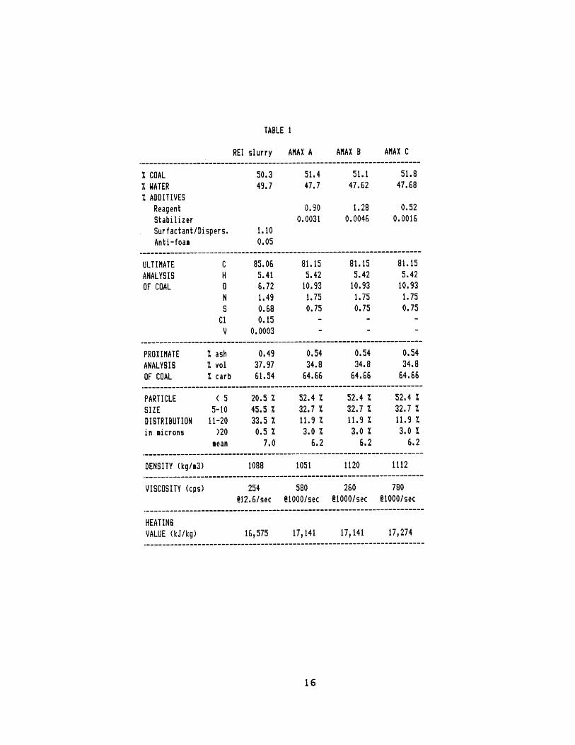
TABLE 1
REI slurry AMAX A AMAX B AMAX C
I COAL 50.3 51.4 51.1 51.8
7 WATER 49.7 47.7 47.62 47.68
7.ADDITIVESReagent 0.90 1.28 0.52Stabilizer 0.0031 0.0046 0.0016
Surfactant/Dispers. 1.10Anti-foaa 0.05
ULTIMATE C 85.06 81.15 81.15 81.15
ANALYSIS H 5.41 5.42 5.42 5.42OF COAL 0 6.72 10.93 10.93 10.93
N 1.49 1.75 1.75 1.75S 0.68 0.75 0.75 0.75
C1 0.15 - - -
V 0.0003 - - -
PROXIMATE % ash 0.49 0.54 0.54 0.54
ANALYSIS % vol 37.97 34.8 34.8 34.8
OF COAL X carb 61.54 64.66 64.66 64.66-----------------------------------------------PARTICLE ( 5 20.5 7 52.4 7 52.4 X 52.4 %
SIZE 5-10 45.5 % 32.7 % 32.7 1 32.7 %
DISTRIBUTION 11-20 33.5 % 11.9 % 11.9 7 11.9 %
in microns >20 0.5 X 3.0 / 3.0 1 3.0 %mean 7.0 6.2 6.2 6.2
-----------------------------------------------DENSITY (kg/m3) 1088 1051 1120 1112
VISCOSITY (cps) 254 580 260 [email protected]/sec @1000/sec @1000/sec p1000/sec
-----------------------------------------------
HEATINGVALUE (kJ/kg) 16,575 17,141 17,141 17,274
16

proximate analysis of the coal between the REI and the
AMAX slurries are the result of different coals used by
the manufacturers, and although the mean particle size of
the REI slurry and the AMAX slurries are similar, the
size distributions are very different. The slurry
densities are all similar. The viscosities were supplied
by the slurry manufacturers and here it should be noted
that since slurry is a non-Newtonian fluid, the viscosity
is dependent on the shear rate. The REI slurry has a
viscosity of 254 centipoise at a shear rate of 12.62
sec while the viscosities of the AMAX slurries were
measured at a shear rate of 1000 sec~I therefore making
exact comparisons not possible.
2. Energies
The net energy per unit mass of the REI slurry was
calculated from the coal energy content (the value was
provided by the manufacturer), the percentages of coal
and water in the slurry, and the energy required to
vaporize the water. The basic equation is as follows:
HV slurry=(%coal)(HV coal) - (%water)(vap.energywater
where the heating values are in kJ/kg and
the vaporization energy of water is 2260 kJ/kg.
17

For the REI slurry, the heating value was determined to
be 16,575 kJ/kg which is approximately 2.5 times less
than that of diesel fuel. This means that the total
volume of slurry injected would have to be 2.5 times
larger than that of diesel fuel to produce the same
amount of work.
The heating values of the AMAX slurries were
provided by the manufacturer and are also summarized in
Table 1.
3. Stoichiometry
The stoichiometric ratio is the ratio of the mass of
air to the mass of fuel for complete combustion to
occur. For example, approximately 15.04 grams of air are
needed to completely combust 1.0 grams of diesel fuel,
therefore the stoichiometric ratio of mass of air to mass
of fuel is 15.04 for diesel fuel. This is determined by
first balancing a simplified chemical equation for
combustion to find the number of moles of air necessary
for complete combustion (combustion in which there is
neither unburned fuel or unused air remaining in the
combustion products). The comparison of the number of
moles of air (oxygen plus nitrogen) times the molecular
weight of air to the number of moles of fuel times the
molecular weight of the fuel is thus the air to fuel
18
ratio by mass for complete combustion, i.e., the
stoichiometric ratio.
To determine the stoiciometric ratio for coal
slurry, several assumptions/simplifications were made.
It was assumed that only the carbon and the hydrogen in
the coal actually reacted with the air, and that the
remainder of the coal components had little effect on the
reaction. The water in the slurry was also assumed to
have little effect, merely passing through the equation
to appear as water vapor in the combustion products. The
stoichiometric ratio for the REI slurry was calculated to
be 5.84:1 mass of air to the mass of slurry and for the
AMAX slurries, 5.66:1. The slight differences between
slurries is due to the slightly different chemical
compositions of the coals used.
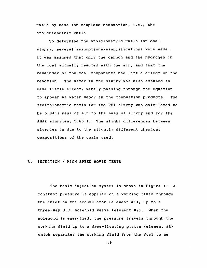
B. INJECTION / HIGH SPEED MOVIE TESTS
The basic injection system is shown in Figure 1. A
constant pressure is applied on a working fluid through
the inlet on the accumulator (element #1), up to a
three-way D.C. solenoid valve (element #2). When the
solenoid Is energized, the pressure travels through the
working fluid up to a free-floating piston (element #3)
which separates the working fluid from the fuel to be
19
FIGURE 1
DIAGRAM OF THE INJECTION SYSTEM
RELIEF
20
INL E T©
injected. Consequently, the fuel is pressurized past a
pressure transducer (element #4) into the injector
(element #6) mounted on the top of the high-pressure bomb
and causes the injector needle to lift. The needle lift
is measured by a Hall-Effect needle lift sensor (element
#5). The high-pressure stainless steel bomb (element #7)
has a clearance of 1.0 inch and is 4.0 inches in
diameter. Two 1.5 inch thick Pyrex windows allow for
viewing and filming the injection spray.
1. The Bomb
The bomb was made of 304 stainless steel with a four
inch diameter bore and a one inch clearance. A pyrex
window was used on each side of the clearance volume to
allow for viewing the injection and each was 4.75 inches
in diameter and 1.5 inches thick. The bomb and windows
were designed for testing up to 1500 psi internal
pressure with an adequate safety margin. The windows
were sealed with o-rings on the inside and were held in
place from the outside with stainless steel flanges and
teflon gaskets. The injector was mounted on the top of
the bomb and nitrogen was used to pressurize the bomb.
21
2. The Injector and Nozzle
The injector used was a commercially available
standard Robert Bosch injector (part # 0-431-201-021)
with an opening pressure which was variable through the
use of an adjustment screw. The nozzle used was an
American Bosch ADN-4S-1 (single hole) pintle nozzle. It
was chosen because it is both commonly used and
relatively inexpensive. This last feature was deemed
desirable because significant permanent nozzle clogging
was foreseen which would necessitate replacement
nozzles. Nozzle clogging did occur frequently but the
nozzles were fairly easy to clean. This will be
discussed in more detail in a later section.
With a pintle nozzle, the spray pattern is dependent
on the shape, or flair, of the needle tip and the
internal profile of the orifice. The present nozzle had
a straight passage and therefore produced a narrow spray
pattern. This nozzle was acceptable for comparison of
atomization properties of the slurries and it was never
intended to be the choice for optimal spray
characteristics. Plans for future research include the
design of a different nozzle expressly for coal slurry
which will be optimized for atomization properties and
spray pattern for the particular engine geometry.
22
3. The Needle Lift Sensor
A Hall-Effect "Microsensor" was used to record the
needle lift of the injector. A samarian-cobalt magnet
was mounted to the lower spring seat in the injector with
high temperature epoxy. This spring seat rode directly
on top of the needle and the resulting changes in the
magnetic field with the needle movement were picked up by
the sensor. The sensor itself was mounted through the
leak-off fitting on the top of the injector. Actual
distances as converted from the needle lift sensor were
highly dependent on the initial distance of the end of
the sensor from the magnet. However, the timing of the
needle lift was most useful and the point where maximum
needle lift occurred was clearly visible.
4. The Pressure Transducer
A Data Instruments AB-5000 pressure transducer with
a maximum rating of 5000 psi was used to measure rail
pressure in the fuel line prior to the injector for the
injection tests.
5. The Solenoid Valve
A three-way 28 volt DC solenoid valve was used to
23

control the injection pulse. It was commercially
available from Circle Seal Corporation and was rated for
6000 psi applications. In a de-energized status, the
injection rail line was open to atmospheric pressure via
the normally open port in the solenoid. When energized,
this port was sealed off and the pressurized port was
opened to the injection rail line. The action of the
solenoid lift itself imposed a minimum on the injection
duration partly because of the pressure equalization of
the three ports as the solenoid needle was lifting but
not yet seated. Attempts to reduce the injection
duration further than a certain value would simply result
in a pressure rise at the injector insufficient to lift
the injector needle. The relatively small passages in
the solenoid valve led to clogging of the solenoid valve
by the slurry and will be discussed in more detail in a
later section. The o-rings, seats, and seals in the
valve did not stand up to repeated use with coal slurry
and had to be frequently replaced.
6. The Accumulator
The accumulator acted as a pressurized reservoir.
It was made from 316 stainless steel schedule 80 pipe,
316 stainless steel schedule 80 end caps, and 150 psi 316
stainless steel flanges. The flanges had an additional
24

four bolt holes drilled to make them eight hole flanges
to prevent leakage through deflection of the flanges.
The end caps and flanges were professionally vacuum
welded to two short pipe sections in such a way that the
accumulator could be taken apart at the middle. A 304
stainless steel stir shaft was installed through the top
end cap and was sealed with a thrust bearing and two
o-rings. This shaft was driven by a high-torque, low-rpm
motor mounted to the outside of the accumulator. The
original intent of this stir shaft was to keep the slurry
agitated during periods between injection tests when the
accumulator was not pressurized. In practice, this was
necessary very few times as the accumulator was kept
pressurized for the most part and later, the system was
modified and slurry was replaced in the accumulator with
another working fluid. The shaft seal though held very
well.
7. The Piston Interface
This device was used to isolate the coal slurry from
the solenoid control valve. It is a five inch long, 304
stainless steel cylinder flanged at each end enclosing a
free-floating aluminum piston inside. The two inch
diameter, one inch thick piston was sealed with an o-ring
in a groove cut into the piston. The device was
25
initially designed to be an interface between high
pressure air and the fuel that was being Injected.
However, the increasing volume on the air side of the
piston as the piston moved greatly effected the time that
the fuel was actually pressurized, and injection
durations shortened with each successive injection until
the fuel was not pressurized long enough to lift the
injection needle. The solution involved using the piston
as the interface between two different fluids, the fuel
being tested and another liquid. Diesel fuel was chosen
as this other liquid because of its lubricative
properties which would prolong the solenoid valve
performance.
8. Valves and Tubing
Concern over possible leaking and clogging of the
valves led to the choice of ball valves over other types
due to the sweeping motion of the ball which would tend
to clean the seats. The valves used in the injection
system were two-way stainless steel ball valves rated to
a maximum operating pressure of 6000 psi. They were
supplied with Kel-F ball seats, Teflon stem packing and
Teflon retainer seals. Throughout the testing, these
valves did not leak, clog, or exhibit signs of excessive
wear despite extensive testing with slurry.
26

The tubing used was stainless steel 1/4 inch (O.D.)
tubing with a wall thickness of .035 inches. It was
rated to a working pressure of approximately 6300 psi.
9. The Movie Camera and Lens
The movie camera used was a Hycam II 16mm motion
picture camera operating on a rotating prism principle
and was used with a Kern lens of 75mm f/1.9. The camera
is equipped with an electronic speed control with an
operating range of 20 to 11,000 full frames/sec. Kodak 4-
X reversal film type 7277 (black and white) was used for
all of the injection tests. With 100 feet long rolls of
film, a frame rate of 6000 frames/sec was used as that
was the fastest rate at which a essentially constant film
speed was obtainable. A triggering signal was sent from
the camera to correspond with this constant frame rate
through the use of a built-in feature which converted
electronic speed control tachometer pulses to feet of
film that had passed through the camera. When the count
reached a value corresponding to the selected triggering
film footage determined from performance charts, the
triggering signal was sent to the control system and the
injection event would be started.
27

10. Lighting
Three 300 Watt lamps were used to provide sufficient
light for the filming. The light from these goose-neck
lamps was bounced off of a 98% reflective card positioned
behind the bomb so that the filmed tests would be
back-lit. Direct frontal lighting produced a picture
that was inferior to those with back-lighting which
showed density variations in the spray patterns very
clearly.
11. Controls
Each injection test was begun by starting the movie
camera. Based on acceleration graphs for the camera, the
film length of 52 feet was used as the point at which the
triggering signal was sent from the camera to the
controller. A manual fire button could also be used to
trigger the event for trial injections. The controller
was a DCI preset counter comparator with which the
duration of the energizing voltage for the solenoid valve
was set. The minimum duration for which the solenoid
could be energized and injection would still occur was
approximately 70 to 80 milliseconds for the coal
slurries, water, and diesel fuel. These minimum
durations both resulted in injection durations of between
28

30 and 40 milliseconds. When the triggering signal
reached the controller, a signal was also sent to the
oscilloscope which triggered it to begin recording both
the injector needle lift and the rail line fuel pressure.
12. Data Acquisition
The rail line fuel pressure trace and the injector
needle lift trace were monitored and recorded on an
oscilloscope which received an external trigger from the
control system. Recorded simultaneously, these two
signals were extremely useful in troubleshooting the
system in the early stages of the testing. In the actual
injection tests, the traces were a history of the event
and a photograph was made of the oscilloscope screen to
permanently record the traces.
13. The Air Compressor
A small, portable high pressure air compressor was
used as the source of the injection pressure and was very
convenient. It was capable of producing 5000 psi air at
a flow rate of 3.0 cubic feet per minute and was equipped
with self-relieving regulator.
29

14. The Rolling Mixer
A problem that must be faced when dealing with a
slurry is that of settling of the solid matter. Because
the REI coal slurry which was used extensively had in it
relatively small amounts of chemical additives, it tended
to settle out rather quickly. The ten gallon shipment
settled to an almost impenetrable sludge on the bottom of
the barrel before it was ready to be tested and had to be
returned to the manufacturer for remixing. A rolling
mixer was then constructed which could spin three, one
gallon jugs of the slurry at 100 rpm thus keeping the
slurry homogenous. The mixer was an arrangement of two
parallel shafts padded with short sections of rubber hose
on which the jugs rode. One of the shafts was driven by
a small electric motor and the second shaft was driven
off of the first with an o-ring belt.
C. INJECTION / STILL PHOTOGRAPHY TESTS
1. The Camera
The camera used to take the still photographs was
specially designed at Arthur D. Little, Inc. to use three
separate lenses simultaneously to photograph different
30

areas of the bomb as the injection occurred. One lens
had no magnification but was used to record a relatively
large part of the spray for general observations about
the overall spray. Two other lenses of 5:1 magnification
were focused on smaller, but overlapping parts of the
spray with one recording the image across the core of the
spray and the other recording the image more at the edge
of the spray. The lenses were separated by a series of
baffles internal to the camera and thus provided three
separate and distinct images of the injection on the
film. A Graflock type holder was mounted at the back of
the camera to hold a type 545 Land film holder. The film
was Polaroid 4x5 Land Film type 55/positive-negative
which provided both an immediate picture of the injection
to determine if the injection was captured and a fine
grain, high resolution negative from which enlargements
were later made.
The camera was mounted on a jack stand and abutted
one window of the bomb with a frontpiece that fit snuggly
inside the flange on the bomb that held the window in
place. It was focused by moving the entire camera closer
to or further from the window while viewing through the
back of the camera. A feature of the camera that was
very important was that the lenses could be moved as a
unit vertically, horizontally, or both with respect to
the frontpiece so that photographs could be taken at
various locations in the bomb (top, middle, bottom). The
31

total travel of the lenses was approximately 2.5 inches.
2. The Light Source
Lighting for the photographs was provided by a 500
nanosecond Xenon flash tube. It was held in place on the
opposite side of the bomb from the camera about 1.5
inches away from the outside of the window. A light
diffuser with a diameter of approximately 1.5 inches was
held in front of the flash tube against the window to
provide a diffused back-lighting.
3. The Controls
The film was exposed not by the action of a shutter,
but by the 500 nanosecond flash of light into an
otherwise shrouded bomb. This meant that a delay circuit
had to be employed to synchronize the flash with the
injection event. This delay was designed at A.D. Little,
Inc. and received its start signal from the "fire" button
of the injection system controls. After the prescribed
delay, a 15,000 volt pulse was sent to the flash tube
circuitry and the 500 nanosecond flash occurred. The
sensitivity of the adjustable delay control was such that
the length of the injection had to be increased somewhat
32

to ensure that the event was actually captured on film.
33
III. SLURRY HANDLING
Coal slurry must be handled in a way different from
more conventional liquid fuels. Suspended in water, the
slurry is a very fine dust that is subject to settling
and which also can clog or partially clog almost any
passage. Whereas most liquid fuels are basically
uneffected by small amounts of evaporation when exposed
to air, the water in coal slurry will evaporate and leave
a slurry of a different composition or worse, coal
sludge. Another significant problem that coal slurry
creates in the fuel injection system is that of wear.
The following sections will discuss problems and
solutions found in the handling of coal slurry.
A. SETTLING
The REI slurry was received just over one month
before the injection system was completed and therefore
was stored and undisturbed for that time. The settling
that occured was so severe that manual mixing was
impossible and mechanical mixing was very difficult. The
entire sample had to be returned to the manufacturer for
remixing which involved mechanical stirring with a large
propeller at a high speed for several hours. This
34
settling exhibited the need for a device that could mix
the slurry on a daily basis. The rolling mixer was then
designed to meet this need by spinning one gallon jugs of
the slurry at about 100 rpm. The jugs of slurry were
stored on their sides so that any settling that did occur
would be remixed by the spinning action of the slurry
itself. If done daily, fifteen minutes of spinning would
keep the slurry in its original state, and approximately
thirty minutes of spinning would negate a weekend's
settling. The AMAX slurry had larger amounts of
stabilizers added to them and did not exhibit settling as
quickly as the REI slurry did. A thorough mixing on the
rolling mixer once or twice a week was sufficient to keep
the samples homogenous.
B. CLOGGING
In general, clogging occurred in small passages in
which the slurry had to lay for any period of time. The
clogging mechanism appeared to be one in which the coal
particles in the slurry agglomerated along the walls and
eventually blocked the passage, a process distinctly
different from slurry drying. Most of the clogs could be
dislodged with running water and a thin piece of wire,
but could definitely not be dislodged by trying to
operate the system with a higher pressure.
35

The most critical clogging occurred in the nozzle.
Initially, it was observed that clogs built up around the
needle tip of the pintle nozzle and caused the needle to
become seized in the nozzle body. Once the needle was
seized, the clogs built up through the three fuel ports
in the nozzle and sometimes into the injector body.
Clogging of this type was eliminated for the most part by
increasing the diametric clearance between the nozzle
body and the needle by .001 inches. Nozzle clogging
continued to occur after the modification but was not as
frequent, and then only after slurry sat in the injector
and nozzle for a period of time. With the REI slurry,
this period of time was approximately 5-7 minutes whereas
with the AMAX slurries the period of time extended to
well over one hour.
Clogging also occurred regularly in the solenoid
valve due to the small passages internal to the valve
mechanism. Again, clogging appeared to be the result of
the water being displaced by coal particles. This
problem was alleviated only by changing the injection
system so that slurry would not have to pass through the
solenoid valve. This was accomplished by employing a
two-fluid system in which diesel fuel was used as a sort
of hydraulic fluid to relay the injection pressure to the
slurry via a free-floating piston interface.
36

C. DRYING
Drying only ever appeared to occur when the slurry
was actually exposed to open air for a short period of
time such as when the clogs were being removed from the
nozzle and the tubing to which the injector was attached
was exposed to the air. With great care, a short
application of pressure could clear the plug of
dried/partly dried slurry from the end of the .25 inch
tubing if the tubing had only been exposed for a short
time. If left exposed to the air for an extended time
(1/2 hour or more) running water and manual extraction
was required.
D. WEAR
The abrasiveness of the coal particles in the slurry
created wear problems in both the nozzle and the solenoid
valve. The noticeable wear in the nozzle occured in the
seat between the needle and the nozzle body. Excessive
wear was deemed to have occurred when the pressurized
nitrogen in the bomb forced its way up into the nozzle
and displaced the slurry from the inside of the nozzle
and injector. Close-up inspection of the needle seat
showed pits and scoring, and although inspection of the
seat inside the nozzle was impossible, it is plausible to
37

assume that it was equally worn.
Significant wear was also observed in the solenoid
valve when slurry was routinely passing through it. The
wear manifested itself when the valve seals and seats
allowed the slurry to leak through the valve. Inspection
showed that although the stainless steel valve was in
perfect condition, the soft, rubber seats were missing
large pieces. Also the several o-rings used as seals
inside the valve were frequently observed to be missing
large scallop shaped chunks. These could have been
caused by abrasion due to the coal particles, but were
more likely caused in the installation of the o-rings as
they were slid past the several ports in the valve
housing. The frequent clogging of the solenoid valve
resulted in frequent removal and reinstallation of these
o-rings which only increased the risk of damage to them.
This problem was eliminated when the slurry was removed
from the solenoid valve in favor of the two-fluid
injection system.
38

IV. PROCEDURES
A. INJECTION / HIGH SPEED MOVIE TESTS
1. Test Matrix
Three different injection pressures were used along
with three different bomb pressures for the series of
injection tests which were conducted. These tests were
filmed using the high speed camera. The injection
pressures were 2000 psi, 3000 psi, and 4200 psi and were
chosen to cover a wide range of pressures within the
limits of the injection system. The bomb pressures were
chosen to be atmospheric pressure, 600 psi, and 1400 psi
(pressurized with nitrogen at room temperature) to cover
a large range of chamber environment densities (1.1
kg/m3, 47.8 kg/m3, and 107.9 kg/m3 respectively). The
first series was done with the REI slurry at the selected
conditions and looked very promising. Differences in
spray pattern were noticeable and the time required for
the injection to penetrate to the opposite wall varied
with the injection pressure. These results will be
discussed in a later section.
A baseline series was done for the same test
conditions with No.2 diesel fuel because much is known
39

about injection of diesel fuel and a second baseline
series was done with water for a direct comparison with
the water-based coal slurry. The three AMAX slurries
with the various viscosities were only tested at two
conditions for a simple comparison with REI slurry. A
complete test matrix is shown in Table 2.
2. System Evolution
The injection system underwent two major
modifications as injection tests were being done. The
modifications had no effect on the actual injection of
the slurries, water, or diesel fuel, but had significant
effect on the repeatability and reliability of the system
as a whole and are worthwhile discussing.
Figure 2a. shows the original system in which slurry
was constantly pressurized to injection pressure in the
accumulator and tubing up to the normally closed port in
the solenoid valve, and additional slurry filled the
tubing up to the nozzle. When the solenoid valve was
lifted and sealed off the relief port (normally open),
the pressure traveled through the tubing to the nozzle
tip and built up until a pressure was reached high enough
to lift the needle and cause an injection. When the
solenoid valve was dropped, the pressure was relieved
through the relief port (normally open) and the injection
40
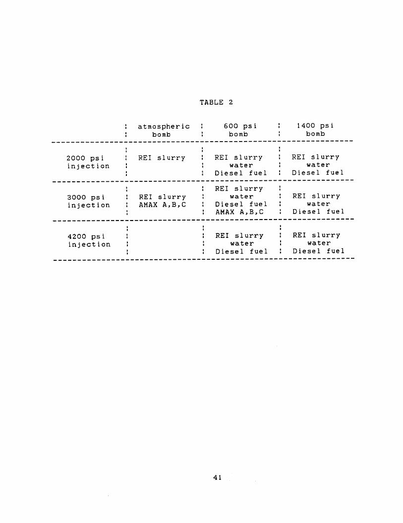
TABLE 2
atmospheric 600 psi 1400 psibomb bomb bomb
--------------------------------------------------------------
2000 psi REI slurry REI slurry REI slurryinjection water water
Diesel fuel Diesel fuel----------------------------------------------
REI slurry3000 psi : REI slurry water REI slurryinjection : AMAX AB,C : Diesel fuel : water
AMAX A,B,C : Diesel fuel----------------------------------------------
4200 psi REI slurry : REI slurryinjection water water
Diesel fuel : Diesel fuel----------------------------------------------
41
g
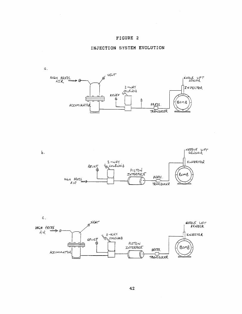
FIGURE 2
INJECTION SYSTEM EVOLUTION
a.
VCuT~
AjatLgE Ljr--
A~ Y.3~
I4rTEkFACEHi4 H P/4
A u?
c.46nL LIFr1
sEcAsop.
PLS5bAIP 19c-0AcI
42
b
HIGH pAc5
pjr- i P -E-3s.Ar)e-
-i -WO

was halted. The problem with this system was clogging
and wear of the solenoid valve. The clogging was very
frequent and was very time consuming to remove.
The solution was to redesign the system so that
slurry did not have to be in or pass through the solenoid
valve. This was done by using a two-fliud system with a
free-floating piston interface to separate the two
fluids. The high pressure air source was plumbed
directly to the normally closed port of the solenoid
where the pressurized slurry had previously been as shown
in Figure 2b. When the solenoid valve was lifted, the
pressure would build up on the air side of the piston
causing the piston to travel the short distance necessary
until the pressure was equalized on the opposite side
which was filled with slurry. The resulting pressure
increase in the rail fuel line would cause the needle to
lift and injection to occur. The closing of the solenoid
valve would relieve the pressure on the air side of the
piston which would again move and equalize the pressure
on the slurry side. An initial normal injection would be
followed by successively shorter injections until the
pressure pulse was not long enough to cause a pressure
rise at the needle tip sufficient to lift the needle.
The problem was simply that with each injection, the
piston was translated a small but finite distance which
increased the volume of the cylinder that had to be
filled with air on the following injection attempt.
43

Since the solenoid valve lift time was kept constant, the
increased time required to build up sufficient injection
pressure on the air side of the piston resulted in a
shorter time of injection. A possible solution would
have been to alter the solenoid valve lift time with each
injection, but this would have been imprecise and
repeatable injections would have been impossible.
A better alternative was to replace the air side of
the system with a fluid, and diesel fuel was chosen
because it would also keep the internal seals of the
solenoid valve lubricated. The system is shown in Figure
2c. that was used successfully for a large number of
injection tests. Diesel fuel was pressurized in the
accumulator as slurry had been in the initial setup and
diesel fuel also filled the system up to the piston
interface although at atmospheric pressure. The lifting
of the solenoid pressurized the diesel fuel and in turn
the piston interface which increased the pressure on the
slurry up to the nozzle and injection occurred as usual.
Pressure was relieved on the diesel fuel through the
relief port of the solenoid valve the same as it had been
when slurry and then air was used.
When the bomb was first pressurized with nitrogen,
the windows fogged up completely. This minor problem was
corrected by drilling a second hole in the bomb which
could be capped and through which nitrogen was allowed to
pass removing the moist air prior to actual
pressurization.
44

3. Method
The high speed movie camera was set up prior to
filling the injection system. The camera was mounted on
a very heavy, sturdy base to prevent movement during
operation due to the high torque of the film drive motor
and once the gross location and height adjustments were
made, the base was not moved. The camera was focused on
a plane approximately in the middle of the clearance
between the bomb windows, but at a distance of four feet
and with a 75mm lens, slight distance discrepancies were
not important. The magnification was such that the whole
bomb (4 inch inside diameter) covered roughly the full
field of view. The focus was rechecked between injection
tests because the bomb was frequently bumped as it was
being cleaned after an injection. The film was loaded
into the camera next and the camera was ready.
It was easiest to use the injection system when
starting with it completely empty of all working fluids.
To use the system, all of the air in the system had to
first be evacuated. The vacuum was first applied to the
slurry side which also sucked the free floating piston to
its limit on that side. With the vacuum sealed on that
side, the valve to the slurry supply was opened and
slurry was sucked into the system. The vacuum was then
shifted to the diesel fuel side and with the valve to the
slurry supply still open, the free floating piston was
45

sucked to its limit on the diesel fuel side pulling
additional slurry into the system and filling it. With a
vacuum sealed on that side, the valve was opened to the
accumulator which was filled with diesel fuel which was
allowed to fill the vacuum on its side of the piston. At
this point, the system was completely filled with the two
working fluids with no pockets of air present. To check
the system, several injections were always made prior to
every test shot ensuring that there were no clogs and
that the pressure rise in the fuel rail line was that
which was set at the air compressor regulator. These
test injections were made into open air outside of the
bomb. If the system was operating correctly, the
injector was then bolted into the side of the bomb and
the bomb was pressurized with nitrogen to the desired
density.
The delayed signal from the camera triggered the
injection and the camera was started by switching the
remote camera switch to the "on" position.
After the injection was completed and the camera had
stopped, the bomb was depressurized, a window was removed
and the slurry was cleaned from the inside of the bomb.
With the window replaced and a new roll of film in the
camera, the system was again ready provided no clogs had
formed in the meantime.
46

4. Other Instrumentation
The pressure trace in the rail fuel line and the
injector needle lift were monitored and they were very
useful in determining where the problems were in the
system. For example, an incomplete pressure rise in the
fuel rail line could either have been due to the presence
of air on one or both sides of the piston interface, or
possibly due to the piston having reached the limit of
its travel. A complete pressure rise in the fuel line
with no needle lift or only a very short uneven needle
lift meant that the injector and/or nozzle were clogged.
The duration of the needle lift (the injection time) was
closely observed because problem-free injections were
very repeatable and thus different durations for
successive injections signalled trouble.
B. INJECTION / STILL PHOTOGRAPHY TESTS
1. Test Matrix
The most extensive testing with the still
photography apparatus was done with the AMAX A slurry
because more information was known for the AMAX slurries
than the REI slurry such as exact additive amounts and
47

also the relationships for those slurries between shear
stress and shear rate over a wide range of shear rates.
Tests with the AMAX A slurry were conducted with the bomb
pressurized to 600 psi with nitrogen and injection
pressures of 3000 and 4200 psi to compare droplet size
differences due to different driving pressures. The
location of the three lenses also was varied from top to
bottom within their travel limits which amounted to just
over one inch in either direction from the center of the
bomb window. Several tests were also conducted with the
AMAX B slurry at an injection pressure of 3000 psi and a
bomb pressure of 600 psi to compare droplet size
differences between slurries essentially identical except
for their viscosities (AMAX A - 580cp, AMAX B - 260cp).
A complete test matrix is shown in Table 3.
2. Method
For the still photography tests, the slurry
injection system was unchanged from the earlier high
speed movie injection tests. Prior to the first
injection, the still photography camera was positioned
and focused on the center plane of the clearance between
the bomb windows. The distance from the camera body to
the bomb flange was noted and for subsequent injection
tests, the camera was returned to this distance and
48

TABLE 3
near top at middle near bottomof bomb : of bomb : of bomb
AMAX A3000 psi inj. 2 tests 3 tests 2 tests600 psi bomb
AMAX A4200 psi inj. 1 test 1 test600 psi bomb
AMAX B3000 psi inj. 1 test 1 test 1 test600 psi bomb
49
refocusing for each shot was not needed. For each test,
the film was loaded into the Land film holder and the
holder was then placed in the camera's Graflock holder.
The film was exposed just prior to the injection by
removing the film cover. As mentioned earlier, the flash
tube was triggered from a delay circuit operating off of
the injection system "fire" button, and it was this flash
that provided the light for the capture of the injection
on film. After the injection was over, the film cover was
replaced and the film was developed according to the
manufacturer's instructions. The bomb was then cleaned,
new film was loaded, the vertical position of the lenses
was adjusted if desired, and the system was ready for
another test pending developed clogs.
50
V. RESULTS AND DISCUSSION
A. HIGH SPEED MOVIES
1. Spray Penetration Analysis
Tracings of the visible fuel jet boundary were made
every few frames for each movie from the start of
injection until the spray impacted the opposite wall of
the bomb. From these tracings, graphs were made of the
time history of the penetration distance of the spray.
Typical penetration histories are shown in Figure 3.
Samples from several movies are shown in Plate 2. A
tangent is fitted to the early part of the tip
penetration trajectories to obtain an initial velocity of
the spray. This velocity is correlated to the injection
pressure and the bomb pressure.
The injection velocity for liquid fuel injection may
be correlated in the form of
U. .=KUinj o
U = [ 2(P .-P )/p ]o inj bomb
where: U is the theoretical initial velocity for an
idealized flow with no head loss,
51

FIGURE 3
TYPICAL PENETRATION HISTORIES
PENETRATION HISTORIES3000 psi ilnjecion, '00 psi bomb
0 2 4
o REI SLURRYiME (ms'I
+ WATER o No.2 DF
52
5
4
3
1V
LU
0
2
1
0

P. is the injection pressure,inj
Pbomb is the pressure in the bomb,
p is the density of the fuel being injected,
K is a flow coefficient depending on nozzle
geometry
For a high enough jet Reynolds Number (Re > 10 4, based on
jet velocity and orifice diameter), the value of K is
approximately constant, and therefore the injection
velocity is not sensitive to the viscosity of the fuel.
The validity of this correlation as applied to coal
slurry is examined here.
The initial velocities from the movies and the
corresponding values for U0 obtained from the injection
conditions were plotted against each other in Figure 4.
The experimental values cover a wide range of fuel types,
injection pressures, and bomb pressures. It can be seen
that the injection velocities for REI slurry, water, No.2
diesel fuel, and the AMAX slurries for the range of
injection conditions fall along the same line,
U. = .25(2(P. .-P )pinj inj bomb
The particular value for the flow coefficient (0.25 in
this case) is dependent on the nozzle internal geometry,
and would be different for different nozzles. More
significantly, however, is the existence of such a
correlation. This is because such a correlation would
53

FIGURE 4
INJECTION CORRELATION
0 50 100 150 200
THEORETICAL
13A
X
REIWateNo. 2AMAXAMAXAMAX
VELOCITY (
SlurryrDiesel FuelA SlurryB SlurryC Slurry
I/s]
54
100
0
H-I:
-J
w
-J
H-
I:
80
60
20
20
0250
enable the injection velocity of coal slurry to be
calculated if the corresponding velocity for diesel fuel
injection is known for the particular injector. Much of
the latter is known by the injector/nozzle manufacturers
who have extensive data bases on the flow of diesel fuel
through their nozzles. The amount of coal slurry
injected based on the U inj the orifice size, and the
injection duration is consistent with experiments
conducted in which the slurry from an injection was
actually collected and weighed.
2. Penetration Times
The time for the spray to penetrate the distance
across the bomb and impact the opposite wall is a rough
indication of how well the spray is being atomized.
Sprays that penetrate more slowly can be said to be
better atomized as smaller droplets have much faster
momentum transfer with the ambient fluid, and tend to be
effected more by the dense environment in the bomb. The
data was analysed to view the effects of injection
pressure and bomb pressure on the spray penetration and
comparisons were also made between the fuels tested.
With the bomb pressure constant, increasing the
injection pressure decreased the time for complete
penetration monotonically for the REI slurry. The
55
results are shown in Figure 5. For No.2 diesel fuel,
increasing the injection pressure had the opposite
effect, with the time of penetration increasing as the
injection pressure was raised. These results may be
explained in terms of the atomizing properties of the
fuels. The time to penetrate a fixed distance depends on
the initial spray velocity and the rate of momentum
transfer of the fuel droplets to the charge air. For the
diesel spray, the initial injection velocity increases
with the pressure drop across the nozzle, but the
resulting atomization yields much finer droplets. The
much faster momentum loss of the fine droplets to the
charge air overpowers the increase in initial velocity,
and the overall penetration time increases. For the coal
slurry spray, the surface energy that holds the drop
together is much larger than that of the diesel droplet
of the same size. This is because of the surface tension
difference between diesel fuel and water, and more
importantly, the significant presence of the extra
liquid-coal particle interface. As a result, the
droplets are rather large, and they do not exchange
momentum readily with the charge air. The penetration
time would, therefore, be mainly dependent on the initial
velocity. With an increasing nozzle pressure drop,
therefore, a shorter penetration time is obtained. An
interesting note is that there appears, to be a certain
injection pressure (" 2300psi) below which diesel fuel
56
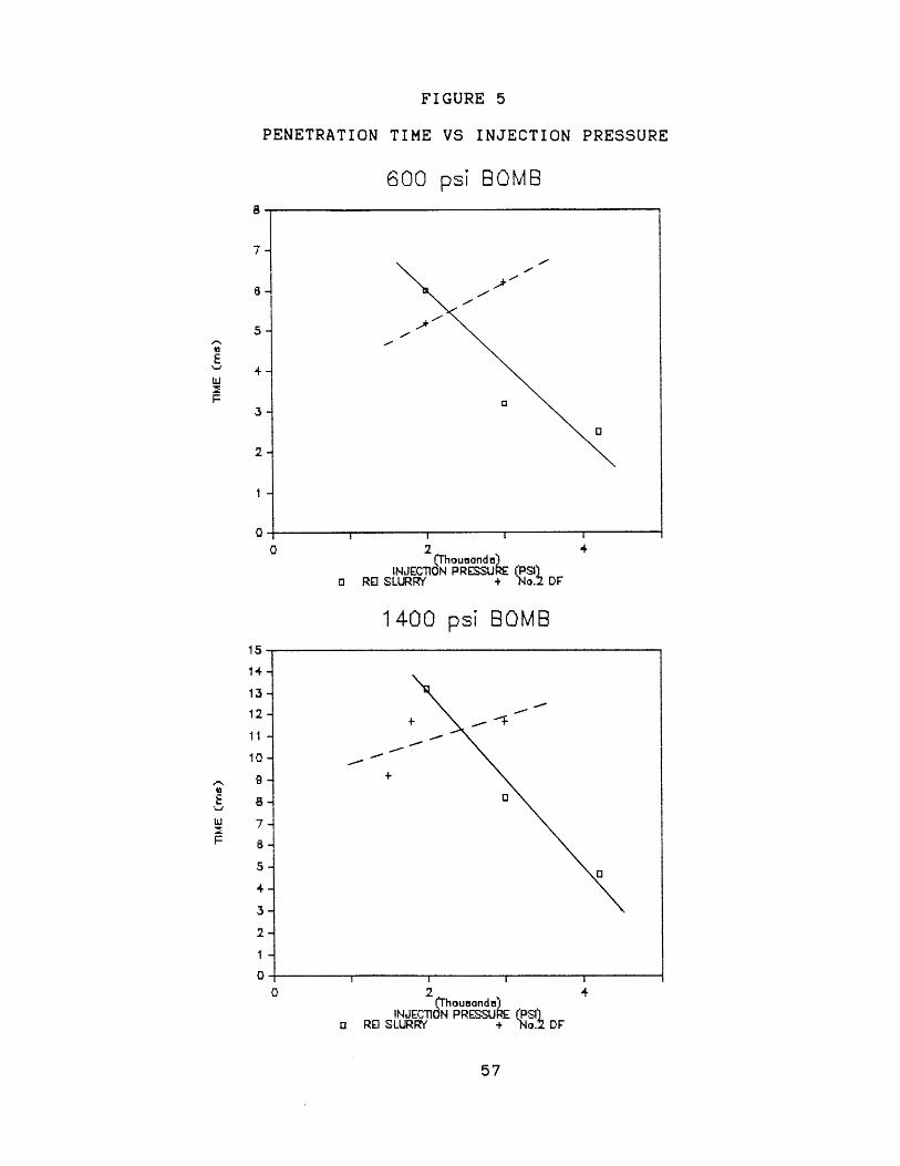
FIGURE 5
PENETRATION TIME VS
600 psi
INJECTION PRESSURE
B0MB8
7-
o 2 4(Thousanda)
INJECTION PRESSU (PSIo RE SLURRY + 190.2 DF
1400 psi BOMB
2(Th oumandai
INJECOlN PRESSU E (PSio RD SLURRY + No.2 DF
4
57
Ewi
5
3a
a
2-
1 -
0
14-
13
12-
11
10-
8-
7-
5 -
F
+
0l
4
3
2
1
00
15
penetrates faster than the slurry and above which slurry
penetrates faster in both the 600 psi bomb and the 1400
psi bomb. Increasing the injection pressure appeared to
have no effect on the penetration time of water which is
likely the result of slightly increased atomization
sufficient enough to slow the droplets and partially
overcome the larger initial velocity thus resulting in
what appears to be a constant penetration time
independent of injection pressure.
For a constant injection pressure, the times for the
sprays to penetrate to the opposite wall increased as the
pressure in the bomb increased for each fuel and water
tested. These results were expected as a denser
environment would invariably slow the penetration of a
spray through it.
No trend in the penetration time could be seen
between the three AMAX slurries each with a different
viscosity. The AMAX slurries were essentially comparable
to the REI slurry as far as the penetration time is
concerned. However, based solely on observations of the
high speed movies, the AMAX slurries did not appear as
finely dispersed as the REI slurry did. This difference
was most likely due to the differences in additives in
the two slurries. The REI slurry had no stabilizer added
- a gel-network forming additive to retard settling - and
consequently appeared to atomize better. Unfortunately
though, the REI slurry settled very quickly and was
58

therefore much more difficult to work with.
3. The Cone Angles
The full cone angle was measured for each injection
directly from the high speed movies at a point in the
injection after the spray had initially impacted the wall
and while the spray was still at a steady state.
Generally, increasing the bomb pressure tended to
increase the cone angle at a given injection pressure for
all of the fuels tested. This tendency also explains why
the penetration time increased with increasing bomb
pressure. The denser the gas in the bomb, the more gas
becomes entrained in the spray which both widens the
spray (cone angle) and consequently slows it.
The AMAX slurries appeared to have larger cone
angles than the REI slurry at identical conditions, but
as with the penetration times, no trend was observable
based on the viscosity differences of the three AMAX
slurries.
As with the effect of injection pressure on the cone
angle analysis, the overall cone angle analyses were
subject to considerable data scatter and were relatively
inconclusive. This may have been caused to a large extent
by the nozzle with which the tests were conducted. The
ADN-4S-1 nozzle was not designed to produce a spray with
59
a large cone angle and therefore may not have produced
marked differences in the cone angles of the various
fuels and at the various conditions tested.
B. STILL PHOTOGRAPHS
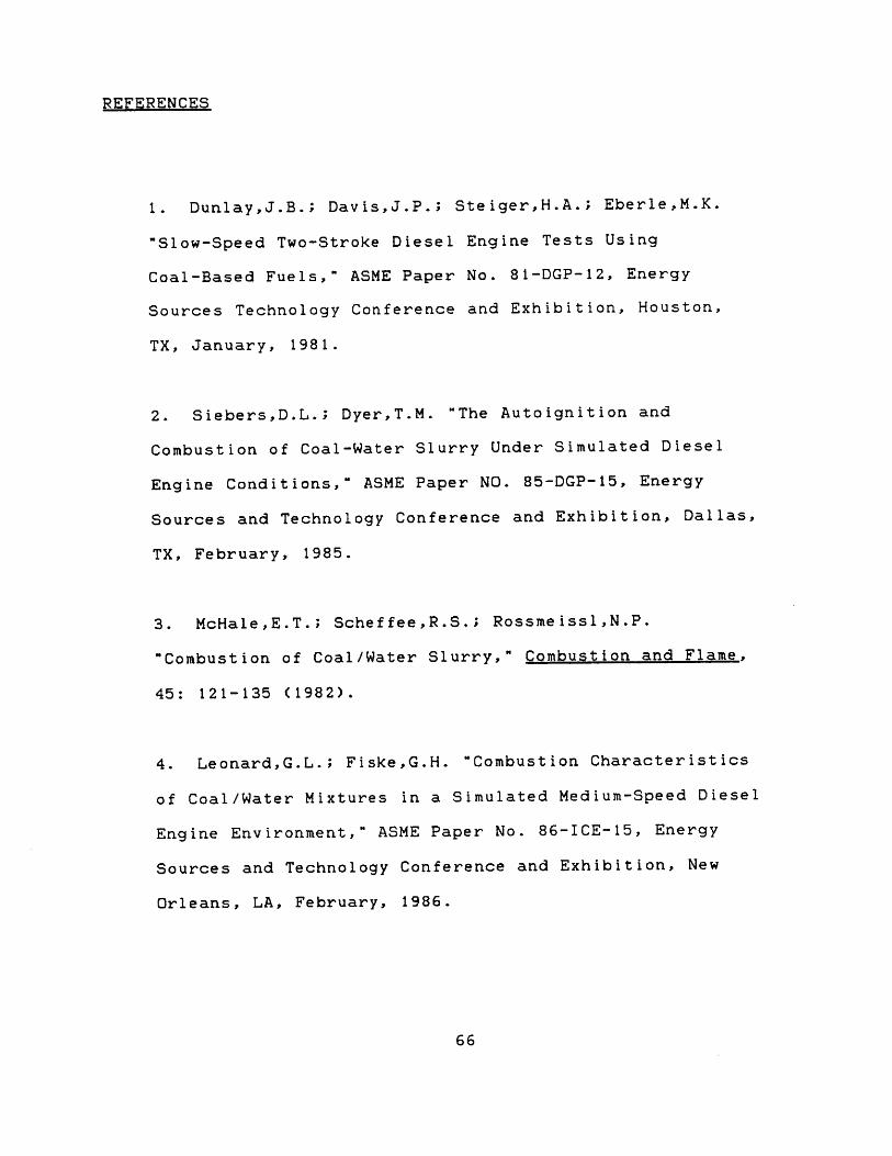
The droplet sizes were manually measured and counted
for each of the higher magnification still photographs
which were enlarged to 20 times actual size.
Representative photographs are shown in Plate 3. In
general, the results showed that the atomization of the
slurry was poor with the largest percentage of droplets
in the range of 50-75 microns. In addition to a
numerical average, a mass average was calculated for
each still photograph as the mass average reflects the
importance of the volume and thus the mass of the
particle. These are shown in Table 4. The particles
mass will ultimately determine the amount of water in
each droplet that will have to be evaporated before the
coal can begin to combust. As was clearly seen in the
lower magnification pictures, the majority of the
injected fuel did not form droplets at all but remained
in a fairly concentrated core and traveled relatively
straight down until contact was made with the opposite
wall.
60

TABLE 4
INJECTIONSLURRY CONDITIONS
inj/bomb psi
AMAXAMAXAMAXAMAXAMAXAMAXAMAXAMAXAMAXAMAXAMAXAMAXAMAXAMAXAMAXAMAXAMAXAMAX
3000/6003000/6003000/6003000/6003000/6003000/6003000/6003000/6003000/6003000/6003000/6004200/6004200/6004200/6003000/6003000/6003000/6003000/600
APPROXIMATE NUMERICALBOMB LOC. AVERAGE
microns microns
TOPTOP
MIDDLEMIDDLEMIDDLEMIDDLEMIDDLEMIDDLEMIDDLEBOTTOMBOTTOM
TOPMIDDLEMIDDLE
TOPMIDDLEMIDDLEBOTTOM
555063658158677165787674906253706498
6 1
MASSAVERAGE
72618398
11286849686
10196
10912089718682
120

From comparisons of identical slurries under
identical conditions, it was observed that the average
particle size in the injection increased from near the
top of the bomb, through the middle of the bomb, to near
the bottom of the bomb. This was not the result of the
smaller droplets agglomerating, but was the result of
some of the slurry that was in the tight core near the
top diffusing outward and forming relatively large
droplets during the course of the injection.
Particle size distributions were plotted for each
photograph to aid comparisons of the droplet sizes in the
spray. These are enclosed in Appendix B. The size
distributions did not vary appreciably from the AMAX A
slurry to the AMAX B slurry at any of the three locations
where still photographs were taken. This finding was in
general agreement with other results which found no
significant difference in spray characteristics
attributable to the different viscosities of the
slurries.
62

VI. CONCLUSIONS
1. Diesel injections of coal-water slurry with identical
pressure traces and needle lift traces are possible with
a standard diesel injector to which only minor
modifications were made.
2. The injection velocities at the nozzle exit may be
correlated to the pressure drop across the nozzle and the
density of the fuel. The correlation was found to be
uniformly valid for No.2 diesel fuel, coal-water slurry,
and water from a standard diesel injector. For the
particular nozzle used, the correlation is in terms of a
flow coefficient of 0.25.
3. Most of the slurry injected did not atomize well and
remained in the relatively tight core. That part of the
injection that did atomize had a mean droplet size in the
range of 50-70 microns.
4. The droplet size distribution of atomized coal-water
slurry does not appear to be effected by increasing
injection pressure.
5. There was no significant difference and no trend in
comparisons of the spray properties of the three AMAX
slurries of different viscosities.
63

VII. FUTURE RESEARCH
There are several recommendations for further
research to be done in the area of the use of coal-water
slurry in diesel engines. Not the least of these
recommendations is an in-depth study of the effects of
chemical additives on the atomization properties and
surface tension of the slurry. The atomization is
crucial for combustion to occur even with a pilot
injection, yet indications from this work show that a
fundamental trade-off may exist between the need for good
atomization and the need to be able to handle the slurry
without excessive settling and clogging problems. More
extensive testing needs to be done to clarify the
observation in this work that the viscosity of the slurry
has little effect on the atomization of the slurry.
Surface tension and chemical additives may have more
impact on the atomization than previously believed.
Combustion tests are the next step for the slurry
and tests are being planned on the Rapid Compression
Machine at M.I.T. A new injector and a new nozzle need
to be designed which will provide the necessary flow
rates for coal-water slurry and which take into account
the clogging tendencies of the slurry. Relatively large
openings and passages along with large clearances between
moving parts are almost necessities.
Finally, bomb injection tests with multi-hole type
64

nozzles should be conducted to note the differences and
similarities of the injection properties of these two
types of nozzles as multi-hole nozzles will eventually be
used in actual engine tests.
65
REFERENCES
1. Dunlay,J.B.; DavisJ.P.; Steiger,H.A.; Eberle,M.K.
"Slow-Speed Two-Stroke Diesel Engine Tests Using
Coal-Based Fuels," ASME Paper No. 81-DGP-12, Energy
Sources Technology Conference and Exhibition, Houston,
TX, January, 1981.
2. SiebersD.L.; Dyer,T.M. "The Autoignition and
Combustion of Coal-Water Slurry Under Simulated Diesel
Engine Conditions," ASME Paper NO. 85-DGP-15, Energy
Sources and Technology Conference and Exhibition, Dallas,
TX, February, 1985.
3. McHaleE.T.; Scheffee,R.S.; Rossmeissl,N.P.
"Combustion of Coal/Water Slurry," Combustion and Flame,
45: 121-135 (1982).
4. Leonard,G.L.; Fiske,G.H. "Combustion Characteristics
of Coal/Water Mixtures in a Simulated Medium-Speed Diesel
Engine Environment," ASME Paper No. 86-ICE-15, Energy
Sources and Technology Conference and Exhibition, New
Orleans, LA, February, 1986.
66

5. Kishan,S.; Bell,S.R.; CatonJ.A. "Numerical
Simulations of Two-Stroke Cycle Engines Using Coal
Fuels," ASME Paper No. 86-ICE-13, Energy-Sources and
Technology Conference and Exhibition, New Orleans, LA,
February, 1986.
6. Tataiah,K; Wood,C.D. "Performance of Coal Slurry Fuel
in a Diesel Engine," SAE Paper No. 800329, 1980.
7. Marshall,H.P.; WaltersD.C.,Jr. "An Experimental
Investigation of a Coal-Slurry Fueled Diesel Engine," SAE
Paper No. 770795, Sept., 1977.
8. RyanT.W.,III; DodgeL.G. "Diesel Engine Injection
and Combustion of Slurries of Coal, Charcoal, and Coke in
Diesel Fuel," SAE Paper No. 840119, SAE International
Congress and Exposition, Detroit, MI, February-March,
1984.
67

APPENDIX A
PLATES
1.
2.
Injection system
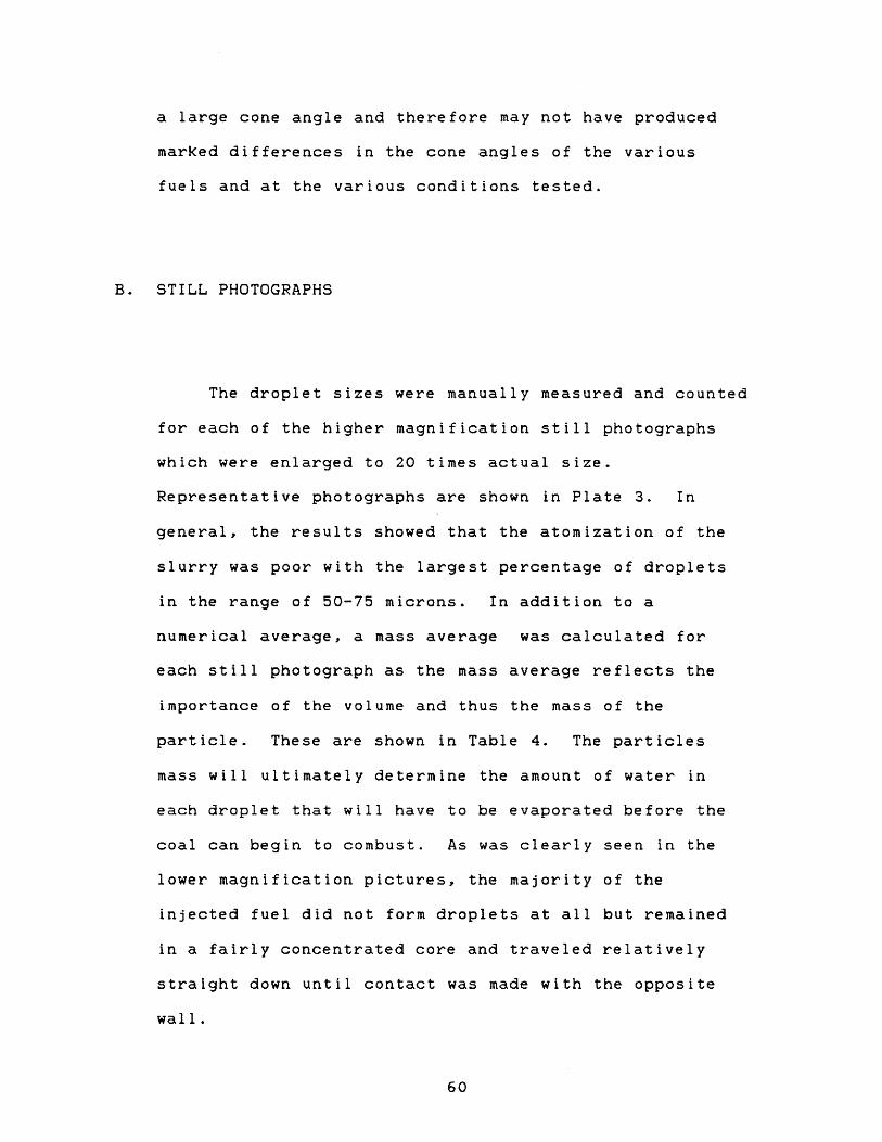
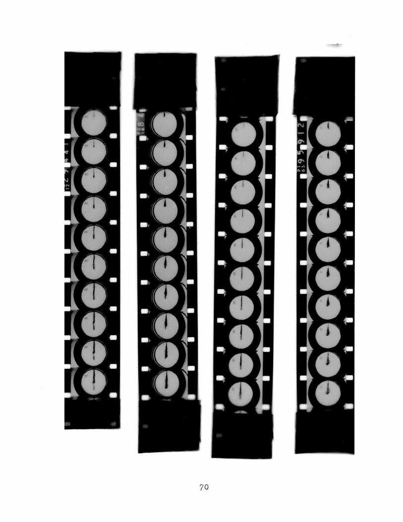
High speed movie comparison
Film clips are in the following order from left
to right: AMAX B Slurry, REI Slurry, Water, No2.
Diesel Fuel. All were taken at identical conditions
of 3000 psi injection pressure and 600 psi bomb
pressure.
3. Droplet Still Photographs
#1. 3000psi injection/600psi bomb, AMAX
#2. 3000psi injection/600psi bomb, AMAX
#3. 3000psi injection/600psi bomb, AMAX
#4. 3000psi injection/600psi bomb, AMAX
NOTE:- Scale on Droplet Still Photographs
1 inch = 2120 microns
0.02 inch z 42 microns
A
A,
A,
B,
is
top
middle
bottom
middle
68

PLATE 1
I
69
70
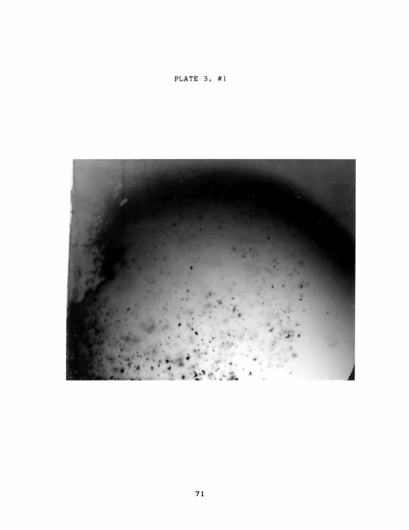
PLATE 3, #1
. . .'-
i~lw I
*Sir
71

PLATE 3, #2
0
F:P.',
4~.
* 0*
6L
72

PLATE 3, #3
73

PLATE 3, #4
* *
* -
#
-
0
0*~
*
S0
S
0
0
5 9
74

APPENDIX B
Droplet Size Distribution Bar Graphs for various
conditions as labeled.
75

DROPLET SIZE DISTRIBUTION3000Yinj/600bomb,AMAX A, +op
30
2826
24-
22 -
16 -
14
12 -
10-
8-
0-
25
76
wM
zw
IL
I I I I I 1 I
75 100 125 150 175 200 225250 275 300 325 350 375
SIZE (micrvns)
/7
m.
40
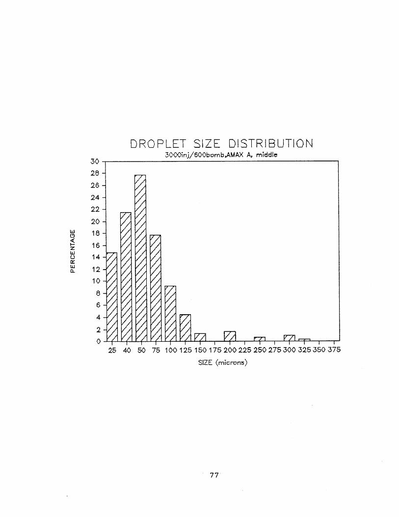
DROPLET SIZE DISTRIBUTION3000inj/600bombAMAX A, middle
-,7
-
-f 7 r1--
28-
26-
24
22
20
18
16
14
12
10
a
6
4
2
0
77
z
L
25 40 50 75 100 125 150 175 200 225 250 275300,325350 375
SIZE (microns)
30n

DROPLET SIZE DISTRIBUTION3000nj/6(00bomb,AMAX A, bot*om
25 40 50 75 100
X--
125 150 175 200 225 250 275 300 325 350 375
SIZE (mirons)
78
30-
281
26
24-
Lii0
wD-
22-
20-
18-
16-14-
12-
10-
8-
4-
2-
0-

DROPLET SIZE DISTRIBUTION3000inj/600bomb,AMA'< B, 'op
25 40 50 75 100 125 150 175 200 225 250 275 300 325 350 375
SIZE (micron:s)
79
w
Li
Li
30-
268
24
22
20
18
16
14
1210
8
6
4
0
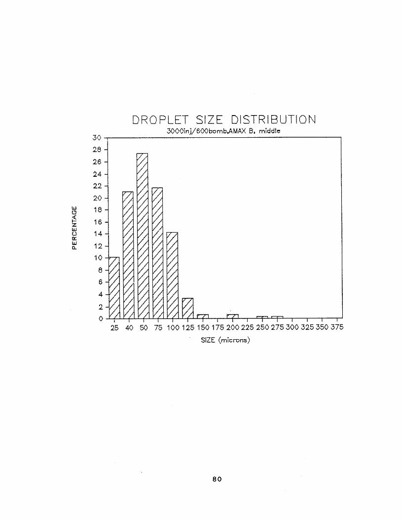
DROPLET SIZE DISTRIBUTION3000nj/60bomb,AMAX B, middIe
/F x
e/ F7
2-6
26$
24-
22-
20-
18-
16-
14-
12-
10-78 -
62-
0-
25
80
30
w
w0
40 50 75 100 125 150 175.200 225 250 275 300 325 350 375
SIZE (microns)
'I

DROPLET SIZE DISTRIBUTION3000inj/600bomb,AMAX B, bttom
26-
24-
22 -
20 -w 18-
14
12 --
10-0
25 40 50 75 100 125 150 175 200 225 250 275 300 325 350 375
SIZE
81
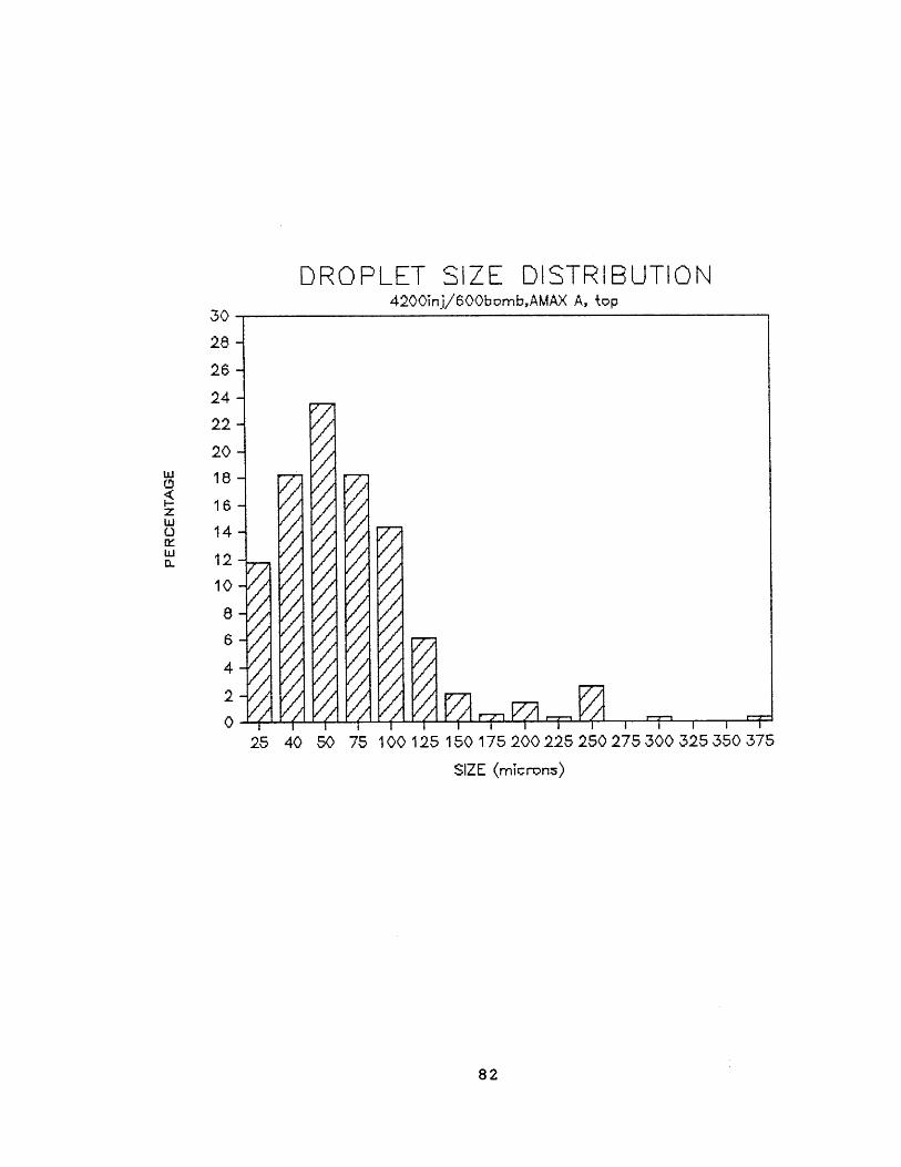
DROPLET SIZE DISTRIBUTION4200nj/600bomb,AMAX A, top
30 -
28 -
26 -
24 -
22 -
20-
18 -
16-14
12 -
10
4.
2
0~
777
-e/
- V I =13
100 125 150 175 200 225 250 275 300 325 350 375
SIZE (microns)
82
w
z
LUi
40 50 7525

DROPLET SIZE DISTRIBUTION4200'inj/600bombAMAX A, middie
7;
30-
28-
26-
24-
22-
20 -
18-
16-
14-
12-
10 -
8-
6-
4-
2-
125 150 175 200 225 250 275 300 325 350 375
SIZE (microns)
83
w
I-zLiiC
Li~I0~
25 40 S0 75 100