audiocodes routing manager (arm)€¦ · audiocodes routing manager (arm) ... 5.2.3 manipulating...
TRANSCRIPT
User's Manual
AudioCodes One Voice Operations Center
AudioCodes Routing Manager (ARM) Version 7.2

User's Manual Contents
Version 7.2 3 ARM
Table of Contents 1 Overview ............................................................................................................ 11
1.1 Features ................................................................................................................. 12 1.2 Benefits .................................................................................................................. 13 1.3 Simplicity ................................................................................................................ 13 1.4 ARM-Routed Devices ............................................................................................. 13 1.5 Third-Party Open-Source Software ........................................................................ 14
2 Getting Started with the ARM ........................................................................... 15
2.1 Logging in ............................................................................................................... 15 2.2 Getting Acquainted with the ARM GUI ................................................................... 15
2.2.1 Getting Acquainted with the Network Page's Map View.......................................... 17 2.2.1.1 Node Information and Actions ..................................................................19 2.2.1.2 VoIP Peer Information and Actions ..........................................................22 2.2.1.3 Connection Information and Actions ........................................................23 2.2.1.4 Peer Connection (Pcon) Information and Actions ....................................24
2.2.2 Getting Acquainted with the Peer Connections Page under NETWORK ................ 26 2.2.3 Getting Acquainted with the Connections Page under NETWORK ........................ 27
3 Defining a Network ............................................................................................ 29
3.1 Adding Connections ............................................................................................... 29 3.2 Synchronizing Topology ......................................................................................... 30 3.3 Building Star Topology ........................................................................................... 31 3.4 Testing a Route ...................................................................................................... 32
4 Administering Users ......................................................................................... 33
4.1 Administering Users ............................................................................................... 33 4.2 Administering User Groups .................................................................................... 35 4.3 Administering the Property Dictionary .................................................................... 37 4.4 Administering LDAP Servers .................................................................................. 37
4.4.1 Adding / Editing a Property ...................................................................................... 40
5 Configuring Settings ......................................................................................... 43
5.1 Configuring Network Services ................................................................................ 43 5.1.1 Editing a Syslog Server ........................................................................................... 43 5.1.2 Adding/Editing an NTP Server ................................................................................. 44
5.2 Configuring Call Flow ............................................................................................. 46 5.2.1 Adding an Attribute Manipulation Group .................................................................. 46 5.2.2 Adding/Editing a Prefix Group ................................................................................. 47 5.2.3 Manipulating Numbers ............................................................................................. 49 5.2.4 Policy Studio ............................................................................................................ 50
5.2.4.1 Example of a Policy Studio Rule ..............................................................52 5.2.5 Configuring Routing Settings ................................................................................... 53
5.3 Performing Administration ...................................................................................... 54 5.3.1 Configuring a Software License ............................................................................... 54 5.3.2 Securing the ARM .................................................................................................... 55 5.3.3 Adding/Editing an Operator ..................................................................................... 56
5.4 Adding a Routing Server ........................................................................................ 57 5.4.1 Editing a Routing Server .......................................................................................... 58
ARM
ARM 4 Document #: LTRT-41883
6 Defining Calls Routing ...................................................................................... 59
6.1 Adding a Routing Group ......................................................................................... 60 6.1.1 Editing a Routing Group .......................................................................................... 61 6.1.2 Moving a Routing Group .......................................................................................... 62 6.1.3 Deleting a Routing Group ........................................................................................ 63
6.2 Adding a New Routing Rule ................................................................................... 64 6.2.1 Editing a Routing Rule ............................................................................................. 66 6.2.2 Moving a Routing Rule ............................................................................................ 67 6.2.3 Deleting a Rule ........................................................................................................ 68
6.3 Testing a Route ...................................................................................................... 68 6.4 Using the Routing Rules Table View Page ............................................................ 69
7 Viewing Alarms ................................................................................................. 71
7.1 Collecting Information via SNMP to Enhance Network Telephony Performance ... 72 7.2 Locating a Specific Alarm ................................................................................... 74
8 Migrating Device Routing to the ARM ............................................................. 75
8.1 Getting Acquainted with Device Types Routing Logic ........................................... 75 8.1.1 SBC Routing Logic .................................................................................................. 75 8.1.2 Media Gateway Routing Logic ................................................................................. 75 8.1.3 Hybrid Device Routing Logic ................................................................................... 76
8.2 Connecting the Device to the ARM Topology Server ............................................. 76 8.3 Migrating SBC/Gateway/Hybrid Routing to the ARM ............................................. 79 8.4 Migrating SBC Routing to the ARM ........................................................................ 80 8.5 Migrating Media Gateway Routing to the ARM ...................................................... 84 8.6 Migrating Hybrid Routing to the ARM ..................................................................... 86
A Checklist for Migrating SBC Routing to the ARM ...........................................89 B Prefixes ..............................................................................................................93 C Examples of Attribute Manipulation Rules .....................................................95 D Routing Path ......................................................................................................99 E Appendix C - Call Routing ..............................................................................101

User's Manual Contents
Version 7.2 5 ARM
List of Figures Figure 2-1: ARM GUI - Network Page - Map View ................................................................................. 15 Figure 2-2: Node Information ................................................................................................................. 19 Figure 2-3: Node Actions ........................................................................................................................ 20 Figure 2-4: Node Update ........................................................................................................................ 20 Figure 2-5: SIP Trunk Information .......................................................................................................... 22 Figure 2-6: PBX Information ................................................................................................................... 22 Figure 2-7: PSTN Information................................................................................................................. 22 Figure 2-8: IP Phone Information ........................................................................................................... 22 Figure 2-9: VoIP Peer Actions ................................................................................................................ 22 Figure 2-10: VoIP Peer Update .............................................................................................................. 23 Figure 2-11: Connection Information ...................................................................................................... 23 Figure 2-12: Connection Actions ............................................................................................................ 23 Figure 2-13: CONNECTION DEFINITION ............................................................................................. 24 Figure 2-14: Peer Connection Information ............................................................................................. 24 Figure 2-15: Peer Connection (Pcon) Actions ........................................................................................ 25 Figure 2-16: ARM GUI - NETWORK Page - Peer Connections ............................................................. 26 Figure 2-17: ARM GUI - Network Page - Connections View .................................................................. 27 Figure 3-1: Add Connection.................................................................................................................... 29 Figure 3-2: Defining a Connection .......................................................................................................... 29 Figure 3-3: Defining a Connection .......................................................................................................... 30 Figure 3-4: Build Star .............................................................................................................................. 31 Figure 3-5: TEST ROUTE ...................................................................................................................... 32 Figure 3-6: Find Routes .......................................................................................................................... 32 Figure 4-1: USERS Page – Users tab .................................................................................................... 33 Figure 4-2: USER DETAILS ................................................................................................................... 34 Figure 4-3: USER DETAILS ................................................................................................................... 34 Figure 4-4: Users Groups ....................................................................................................................... 35 Figure 4-5: USER GROUP DETAILS ..................................................................................................... 35 Figure 4-6: USERS Page – LDAP Servers tab ...................................................................................... 37 Figure 4-7: LDAP Server Settings .......................................................................................................... 37 Figure 4-8: LDAP SERVER SETTINGS ................................................................................................. 39 Figure 4-9: Property Dictionary .............................................................................................................. 40 Figure 4-10: PROPERTY ....................................................................................................................... 40 Figure 5-1: Network Services ................................................................................................................. 43 Figure 5-2: SYSLOG DETAILS .............................................................................................................. 44 Figure 5-3: NTP Servers ......................................................................................................................... 44 Figure 5-4: NTP Server Details .............................................................................................................. 45 Figure 5-5: Attribute Manipulation .......................................................................................................... 46 Figure 5-6: ATTRIBUTE MANIPULATION GROUP ............................................................................... 46 Figure 5-7: Prefix Groups ....................................................................................................................... 48 Figure 5-8: Prefix Group Details ............................................................................................................. 48 Figure 5-9: Number Manipulation ........................................................................................................... 49 Figure 5-10: POLICY STUDIO ............................................................................................................... 50 Figure 5-11: Policy Studio Settings ........................................................................................................ 50 Figure 5-12: Policy Studio Rule Example ............................................................................................... 52 Figure 5-13: ROUTING SETTINGS ....................................................................................................... 53 Figure 5-14: Software License Page ...................................................................................................... 54 Figure 5-15: Security Page ..................................................................................................................... 55 Figure 5-16: OPERATORS ..................................................................................................................... 56 Figure 5-17: OPERATOR DETAILS ....................................................................................................... 56 Figure 5-18: Routing Servers ................................................................................................................. 57 Figure 5-19: SERVER DETAILS ............................................................................................................ 57 Figure 5-20: Routing Servers ................................................................................................................. 58 Figure 5-21: SERVER DETAILS ............................................................................................................ 58 Figure 6-1: ROUTING ............................................................................................................................. 59 Figure 6-2: Add Group ............................................................................................................................ 60 Figure 6-3: ROUTING GROUP SETTINGS ........................................................................................... 60

ARM
ARM 6 Document #: LTRT-41883
Figure 6-4: Edit Group ............................................................................................................................ 61 Figure 6-5: Routing Group ...................................................................................................................... 61 Figure 6-6: ROUTING GROUP SETTINGS ........................................................................................... 61 Figure 6-7: Move Icon ............................................................................................................................. 62 Figure 6-8: MOVE ROUTING GROUP ................................................................................................... 62 Figure 6-9: Edit Group ............................................................................................................................ 63 Figure 6-10: Routing Group .................................................................................................................... 63 Figure 6-11: Add Rule ............................................................................................................................ 64 Figure 6-12: New Routing Rule .............................................................................................................. 64 Figure 6-13: Edit Rule ............................................................................................................................. 66 Figure 6-14: Move Icon ........................................................................................................................... 67 Figure 6-15: Move Routing Rule ............................................................................................................ 67 Figure 6-16: Delete Icon ......................................................................................................................... 68 Figure 6-17: Delete Icon ......................................................................................................................... 68 Figure 6-18: Routing Rules Table View Page ........................................................................................ 69 Figure 7-1: Alarms – Active Alarms + Alarm Summary .......................................................................... 71 Figure 7-2: Alarms – History Alarms ...................................................................................................... 72 Figure 7-3: SNMP Destination Details .................................................................................................... 72 Figure 7-4: Search Field ......................................................................................................................... 74 Figure 7-5: Searching for a Specific Alarm ............................................................................................. 74 Figure 8-1: Web Interface - HTTP Remote Services ............................................................................. 76 Figure 8-2: Web Interface - HTTP Remote Services – Add Row ........................................................... 76 Figure 8-3: Web Interface - HTTP Remote Services – HTTP Remote Hosts ........................................ 77 Figure 8-4: Web Interface - HTTP Remote Services - HTTP Remote Hosts ......................................... 77 Figure 8-5: Web Interface - HTTP Remote Services - HTTP Remote Hosts - Edit ............................... 77 Figure 8-6: Web Interface – Device Connected to ARM Topology Server ............................................ 78 Figure 8-7: Web Interface – Routers ...................................................................................................... 78 Figure 8-8: Web Interface – SIP Interface Table .................................................................................... 79 Figure 8-9: Web Interface – SIP Interface Table - Configuring an SIP Interface ................................... 79 Figure 8-10: Web Interface – IP Group Table ........................................................................................ 80 Figure 8-11: Web Interface – IP Group Table - Configuring an IP Group .............................................. 80 Figure 8-12: Web Interface - 'Used By Routing Server' Parameter ....................................................... 81 Figure 8-13: Web Interface – IP-to-IP Routing Table ............................................................................. 81 Figure 8-14: Web Interface – IP-to-IP Routing Table – Add Row – Rule tab ......................................... 81 Figure 8-15: Web Interface – Message Condition Table – Edit Row ..................................................... 82 Figure 8-16: Web Interface – Message Condition Table – Edit Row ..................................................... 82 Figure 8-17: Web Interface – IP-to-IP Routing Table – Add Row – Action tab ...................................... 82 Figure 8-18: Web Interface – IP-to-IP Routing Table ............................................................................. 83 Figure 8-19: Configuring a Routing Rule in the ARM ............................................................................. 83 Figure 8-20: Web Interface - Routing General Parameters Page .......................................................... 84 Figure 8-21: Web Interface - IP Group Table Page ............................................................................... 84 Figure 8-22: Web Interface - Trunk Group ............................................................................................. 85 Figure 8-23: Proxy Set for the SBC Application ..................................................................................... 86 Figure 8-24: Proxy Set Address for the SBC Application ....................................................................... 86 Figure 8-25: IP Group for the SBC Application ...................................................................................... 87 Figure 8-26: Proxy Set for Media Gateway Application ......................................................................... 87 Figure 8-27: Proxy Set Address for Media Gateway Application ........................................................... 88 Figure 8-28: IP Group for Media Gateway Application ........................................................................... 88 Table A-1: SBC Migration Checklist ....................................................................................................... 89 Table B-1: Prefixes ................................................................................................................................. 93

User's Manual Contents
Version 7.2 7 ARM
List of Tables Table 2-1: ARM GUI – Map View ........................................................................................................... 16 Table 2-2: Network Page's Map View – Network Entities ...................................................................... 17 Table 2-3: Network Page's Map View – Viewing Node Information ....................................................... 19 Table 4-1: User Group Details ................................................................................................................ 36 Table 4-2: LDAP Server Settings ........................................................................................................... 38 Table 4-3: Add Property ......................................................................................................................... 42 Table 5-1: SYSLOG DETAILS ............................................................................................................... 44 Table 5-2: NTP Server Details ............................................................................................................... 45 Table 5-3: ATTRIBUTE MANIPULATION GROUP ................................................................................ 47 Table 5-4: Prefix Group Details .............................................................................................................. 48 Table 5-5: Global Incoming Number Manipulation ................................................................................. 49 Table 5-6: Policy Studio Settings ........................................................................................................... 51 Table 5-7: Routing Settings .................................................................................................................... 53 Table 5-8: Security Settings ................................................................................................................... 55 Table 5-9: Operator Details .................................................................................................................... 56 Table 5-10: Routing Server Details ........................................................................................................ 57 Table 5-11: Server Details ...................................................................................................................... 58 Table 6-1: Defining a New Routing Rule ................................................................................................ 65 Table 7-1: SNMP Destination Details ..................................................................................................... 73

ARM
ARM 8 Document #: LTRT-41883
This page is intentionally left blank.
User's Manual Notices
Version 7.2 9 ARM
Notice This User's Manual shows how to use the AudioCodes Routing Manager (ARM). Information contained in this document is believed to be accurate and reliable at the time of printing. However, due to ongoing product improvements and revisions, AudioCodes cannot guarantee accuracy of printed material after the Date Published nor can it accept responsibility for errors or omissions. Updates to this document and other documents can be viewed by registered customers at http://www.audiocodes.com/downloads.
© 2016 AudioCodes Inc. All rights reserved This document is subject to change without notice.
Date Published: Nov-22-2016
Trademarks AudioCodes Ltd. All rights reserved. AudioCodes, AC, HD VoIP, HD VoIP Sounds Better, IPmedia, Mediant, MediaPack, What’s Inside Matters, OSN, SmartTAP, User Management Pack, VMAS, VoIPerfect, VoIPerfectHD, Your Gateway To VoIP, 3GX, VocaNom, AudioCodes One Voice and CloudBond are trademarks or registered trademarks of AudioCodes Limited. All other products or trademarks are property of their respective owners. Product specifications are subject to change without notice.
WEEE EU Directive Pursuant to the WEEE EU Directive, electronic and electrical waste must not be disposed of with unsorted waste. Please contact your local recycling authority for disposal of this product.
Customer Support Customer technical support and services are provided by AudioCodes or by an authorized AudioCodes Service Partner. For more information on how to buy technical support for AudioCodes products and for contact information, please visit our Web site at www.audiocodes.com/support.
Abbreviations and Terminology Each abbreviation, unless widely used, is spelled out in full when first used.
ARM
ARM 10 Document #: LTRT-41883
Related Documentation
Manual Name
ARM Installation Manual
Mediant 9000 SBC User's Manual
Mediant 4000 SBC User's Manual
Mediant 2600 E-SBC User's Manual
Mediant SE SBC User's Manual
Mediant SE-H SBC User's Manual
Mediant VE SBC User's Manual
Mediant VE-H SBC User's Manual
Mediant 1000B Gateway and E-SBC and Mediant 1000B MSBR User's Manual
Mediant 800B Gateway and E-SBC and Mediant 800B MSBR User's Manual
Mediant 500 E-SBC User's Manual
Mediant 500L MSBR and Mediant 500 MSBR User's Manual
EMS Server IOM Manual
EMS User's Manual
Documentation Feedback AudioCodes continually strives to produce high quality documentation. If you have any comments (suggestions or errors) regarding this document, please fill out the Documentation Feedback form on our Web site at http://www.audiocodes.com/downloads.
Document Revision Record
LTRT Description
41880 Initial release
41881 New features: Adding ADs, Users and Users Groups, Adding an LDAP Property, Adding a User, Adding a User Property, Adding a User Group, Configuring Settings, Adding Operators, Adding Routing Servers, Configuring a Syslog Server, Adding a Number Manipulation Group, Adding a Prefix Group, Adding an NTP Server, Adding a Software License, Routing
41882 New: Section 8, Migrating Media Gateway Routing
41883 Modified performance capability, added new GUI screens, deleted Network Table view, added Time-Base Routing, added Policy Studio, other minor additions.
User's Manual 1. Overview
Version 7.2 11 ARM
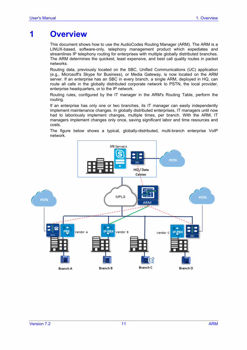
1 Overview This document shows how to use the AudioCodes Routing Manager (ARM). The ARM is a LINUX-based, software-only, telephony management product which expediates and streamlines IP telephony routing for enterprises with multiple globally distributed branches. The ARM determines the quickest, least expensive, and best call quality routes in packet networks. Routing data, previously located on the SBC, Unified Communications (UC) application (e.g., Microsoft's Skype for Business), or Media Gateway, is now located on the ARM server. If an enterprise has an SBC in every branch, a single ARM, deployed in HQ, can route all calls in the globally distributed corporate network to PSTN, the local provider, enterprise headquarters, or to the IP network. Routing rules, configured by the IT manager in the ARM's Routing Table, perform the routing. If an enterprise has only one or two branches, its IT manager can easily independently implement maintenance changes. In globally distributed enterprises, IT managers until now had to laboriously implement changes, multiple times, per branch. With the ARM, IT managers implement changes only once, saving significant labor and time resources and costs. The figure below shows a typical, globally-distributed, multi-branch enterprise VoIP network.
ARM
ARM 12 Document #: LTRT-41883
VoIP networks like this typically require: Distributed routing & policy enforcement Distributed PSTN Multiple VoIP network elements configurations (i.e., SBC, Media Gateway) Multiple dial plans SIP Interworking between IP PBXs Large number of end users policies Efficient ARM routing management
1.1 Features ARM features are as follows: Centralized, enterprise-wide session routing management Centralized & optimized PSTN routing Automatic discovery of VoIP network elements Smart dial plan management
• Centralized dial plan logic; simple, clear, intuitive and easy to maintain • Dialing plan dry test by ‘Test Route’ simulation • Incoming number manipulation • Outgoing number manipulation • User properties manipulation
Reduces SIP trunk costs • Implements Tail-End-Hop-Off Routing • Assigns a number of actions to routing rules with different sequence • Source and destination number manipulation
Advanced routing based on user properties Automatic topology network generation Manual network generation (simply drawing lines between dots) On-the-fly routing calculation:
• Centralized management of Network Routing Rules • Routing decision is based on source / destination call parameters, and user
properties • Predefined weights on connections • User information from external Data Bases (e.g., LDAP) • Flexible API
Intuitive graphical representation of the enterprise VoIP network Personalized Call Routing Applications
• Communication-Enabled Business Process • Full on-line management and routing via REST API • Fallback to SBC routing table if call does not match ARM configuration
User's Manual 1. Overview
Version 7.2 13 ARM
1.2 Benefits The ARM benefits users as follows: Reduces operational time spent on designing and provisioning network topology Reduces OPEX, avoiding routing configuration of VoIP network elements Reduces time spent implementing network evolutions such as:
• Adding new connections to PSTN (e.g., SIP trunks) • Adding new branches to the enterprise VoIP network • Modifying user voice services privileges
1.3 Simplicity VoIP network elements registering in the ARM Auto-discovery of VoIP peers One-click topology network creation, star formation Customized topology network.
• Configuring a connection is as simple as drawing a line. • Modify by adding, deleting and changing connections
ARM connects to users data base
1.4 ARM-Routed Devices The following devices can be routed by the ARM: Mediant 9000 SBC Mediant 4000 SBC Mediant 2600 E-SBC Mediant SE/VE SBC Mediant 1000B Gateway and E-SBC and Mediant 1000B MSBR Mediant 800B Gateway and E-SBC and Mediant 800B MSBR Mediant 500 E-SBC Mediant 500L MSBR and Mediant 500 MSBR
ARM
ARM 14 Document #: LTRT-41883
1.5 Third-Party Open-Source Software The following third-party open-source software is supported by the ARM: CentOS Linux 6.6 Spring Framework (released under version 2.0) MariaDB relational database management system ActiveMQ (using the Apache 2.0 license) HiberNate (projects licensed under Lesser General Public License (LGPL) v2.1) Log4J (Apache License 2.0) Guava (Google core libraries - Apache License 2.0) jackson-core Apache Commons Logging™ HttpClient - Apache XStream (Group: com.thoughtworks.xstream) Jersey client Joda-Time SLF4J (Simple Logging Facade for Java) HikariCP Java 6 Aspectj™ extension to Java SNMP4J (Open Source SNMP API for Java) Mockito
User's Manual 2. Getting Started with the ARM
Version 7.2 15 ARM
2 Getting Started with the ARM After installing the ARM and performing initial configuration (see the ARM Installation Manual), you can get started with the ARM.
2.1 Logging in This section shows how to log in.
To log in:
1. Point your web browser to the ARM's IP address and press Enter. 2. In the login screen that opens, log in using the default username and password
(Operator and Operator). It's advisable to change these as soon as possible (see Section 5.3.3 for instructions on how to change them).
The tool opens in the Network page, Map view (default) in your browser. By default, all VoIP entities managed in the network are displayed.
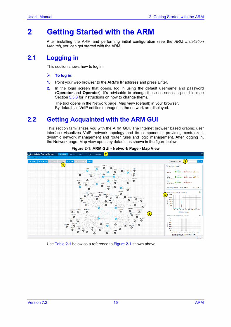
2.2 Getting Acquainted with the ARM GUI This section familiarizes you with the ARM GUI. The Internet browser based graphic user interface visualizes VoIP network topology and its components, providing centralized, dynamic network management and router rules and logic management. After logging in, the Network page, Map view opens by default, as shown in the figure below.
Figure 2-1: ARM GUI - Network Page - Map View
Use Table 2-1 below as a reference to Figure 2-1 shown above.
1
2
3
4
5
ARM
ARM 16 Document #: LTRT-41883
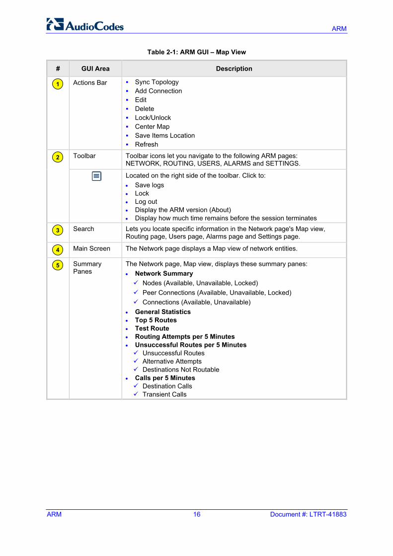
Table 2-1: ARM GUI – Map View
# GUI Area Description
Actions Bar Sync Topology Add Connection Edit Delete Lock/Unlock Center Map Save Items Location Refresh
Toolbar Toolbar icons let you navigate to the following ARM pages:
NETWORK, ROUTING, USERS, ALARMS and SETTINGS.
Located on the right side of the toolbar. Click to: • Save logs • Lock • Log out • Display the ARM version (About) • Display how much time remains before the session terminates
Search Lets you locate specific information in the Network page's Map view,
Routing page, Users page, Alarms page and Settings page.
Main Screen The Network page displays a Map view of network entities.
Summary Panes
The Network page, Map view, displays these summary panes: • Network Summary Nodes (Available, Unavailable, Locked) Peer Connections (Available, Unavailable, Locked) Connections (Available, Unavailable)
• General Statistics • Top 5 Routes • Test Route • Routing Attempts per 5 Minutes • Unsuccessful Routes per 5 Minutes Unsuccessful Routes Alternative Attempts Destinations Not Routable
• Calls per 5 Minutes Destination Calls Transient Calls
1
2
3
4
5
User's Manual 2. Getting Started with the ARM
Version 7.2 17 ARM
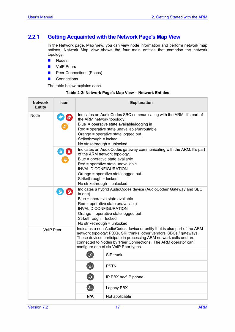
2.2.1 Getting Acquainted with the Network Page's Map View In the Network page, Map view, you can view node information and perform network map actions. Network Map view shows the four main entities that comprise the network topology: Nodes VoIP Peers Peer Connections (Pcons) Connections
The table below explains each.
Table 2-2: Network Page's Map View – Network Entities
Network Entity
Icon Explanation
Node
Indicates an AudioCodes SBC communicating with the ARM. It's part of the ARM network topology. Blue = operative state available/logging in Red = operative state unavailable/unroutable Orange = operative state logged out Strikethrough = locked No strikethrough = unlocked
Indicates an AudioCodes gateway communicating with the ARM. It's part of the ARM network topology. Blue = operative state available Red = operative state unavailable INVALID CONFIGURATION Orange = operative state logged out Strikethrough = locked No strikethrough = unlocked
Indicates a hybrid AudioCodes device (AudioCodes' Gateway and SBC in one). Blue = operative state available Red = operative state unavailable INVALID CONFIGURATION Orange = operative state logged out Strkethrough = locked No strikethrough = unlocked
VoIP Peer Indicates a non-AudioCodes device or entity that is also part of the ARM network topology: PBXs, SIP trunks, other vendors' SBCs / gateways. These devices participate in processing ARM network calls and are connected to Nodes by 'Peer Connections'. The ARM operator can configure one of six VoIP Peer types.
SIP trunk
PSTN
IP PBX and IP phone
Legacy PBX
N/A Not applicable
ARM
ARM 18 Document #: LTRT-41883
Network Entity
Icon Explanation
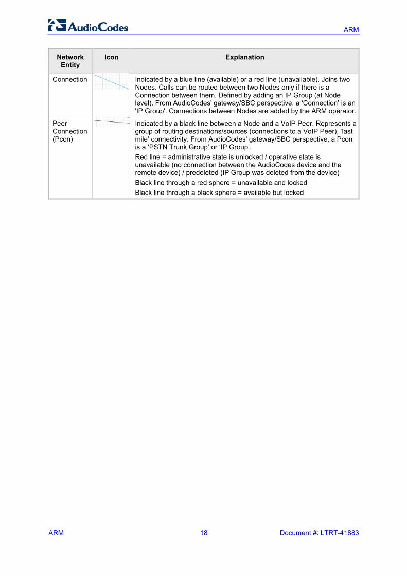
Connection
Indicated by a blue line (available) or a red line (unavailable). Joins two Nodes. Calls can be routed between two Nodes only if there is a Connection between them. Defined by adding an IP Group (at Node level). From AudioCodes' gateway/SBC perspective, a ‘Connection’ is an 'IP Group'. Connections between Nodes are added by the ARM operator.
Peer Connection (Pcon)
Indicated by a black line between a Node and a VoIP Peer. Represents a group of routing destinations/sources (connections to a VoIP Peer), ‘last mile’ connectivity. From AudioCodes' gateway/SBC perspective, a Pcon is a ‘PSTN Trunk Group’ or ‘IP Group’. Red line = administrative state is unlocked / operative state is unavailable (no connection between the AudioCodes device and the remote device) / predeleted (IP Group was deleted from the device) Black line through a red sphere = unavailable and locked Black line through a black sphere = available but locked
User's Manual 2. Getting Started with the ARM
Version 7.2 19 ARM
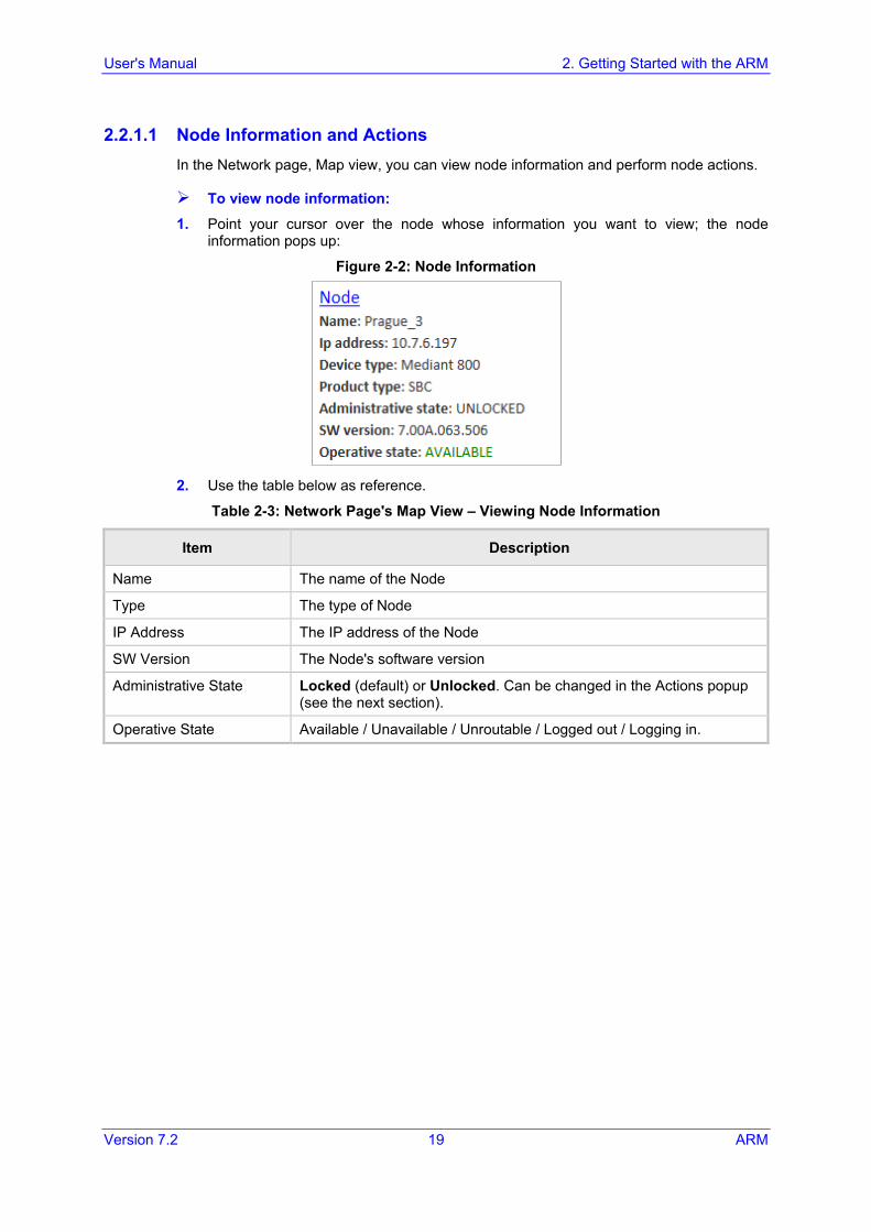
2.2.1.1 Node Information and Actions In the Network page, Map view, you can view node information and perform node actions.
To view node information: 1. Point your cursor over the node whose information you want to view; the node
information pops up:
Figure 2-2: Node Information
2. Use the table below as reference.
Table 2-3: Network Page's Map View – Viewing Node Information
Item Description
Name The name of the Node
Type The type of Node
IP Address The IP address of the Node
SW Version The Node's software version
Administrative State Locked (default) or Unlocked. Can be changed in the Actions popup (see the next section).
Operative State Available / Unavailable / Unroutable / Logged out / Logging in.
ARM
ARM 20 Document #: LTRT-41883
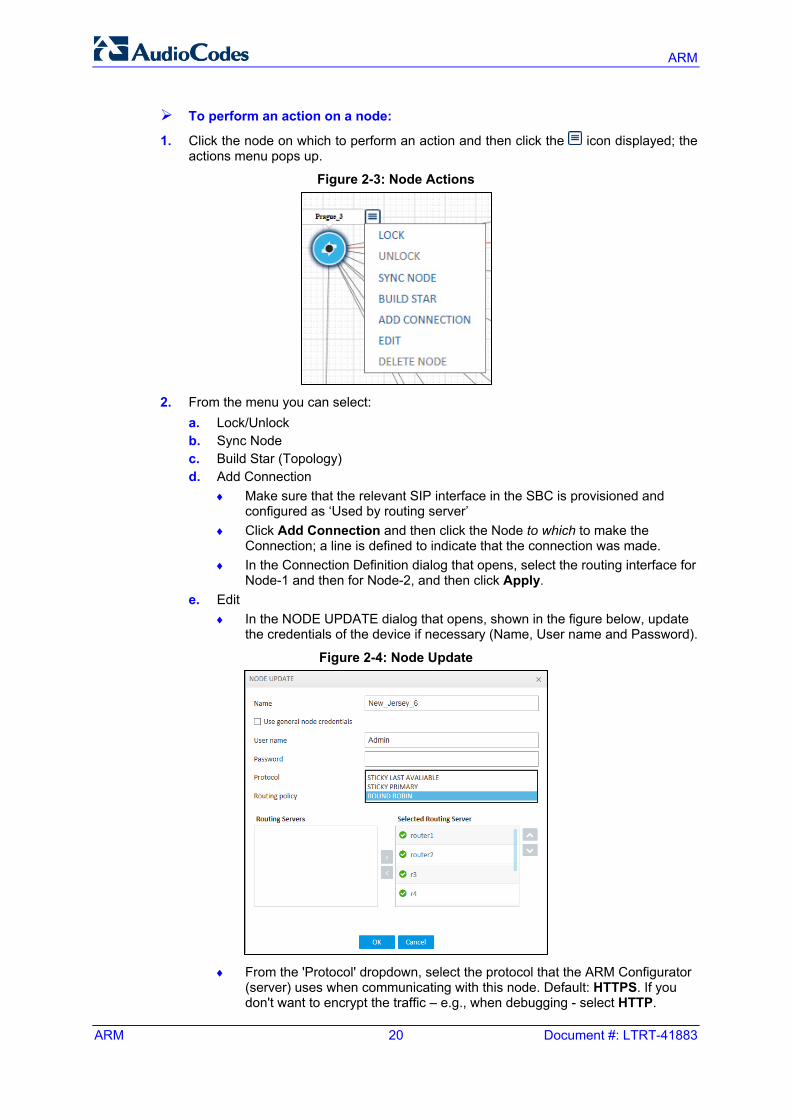
To perform an action on a node:
1. Click the node on which to perform an action and then click the icon displayed; the actions menu pops up.
Figure 2-3: Node Actions
2. From the menu you can select:
a. Lock/Unlock b. Sync Node c. Build Star (Topology) d. Add Connection
♦ Make sure that the relevant SIP interface in the SBC is provisioned and configured as ‘Used by routing server’
♦ Click Add Connection and then click the Node to which to make the Connection; a line is defined to indicate that the connection was made.
♦ In the Connection Definition dialog that opens, select the routing interface for Node-1 and then for Node-2, and then click Apply.
e. Edit ♦ In the NODE UPDATE dialog that opens, shown in the figure below, update
the credentials of the device if necessary (Name, User name and Password).
Figure 2-4: Node Update
♦ From the 'Protocol' dropdown, select the protocol that the ARM Configurator
(server) uses when communicating with this node. Default: HTTPS. If you don't want to encrypt the traffic – e.g., when debugging - select HTTP.
User's Manual 2. Getting Started with the ARM
Version 7.2 21 ARM
♦ From the 'Routing policy' dropdown, select either: - Round Robin (default). For each request, the node selects a different
router. - Sticky Last Available. The node picks the first available router from the
routers that are listed in order of priority under 'Selected Routing Server', and stays with it until it fails. If it fails, the node continues down the list. The node therefore only functions with one router at a time.
- Sticky Primary. The node picks the first available router from the routers that are listed in order of priority under 'Selected Routing Server', and stays with it until it fails. If it fails, the node goes to the highest available router in the list. The node therefore functions at any time with the highest available router in the list.
♦ Specifying Routing Server
- The Routing Servers section allows the network administrator to select routers to operate with a selected node. This is useful, for example, if an enterprise has servers located in different regions and the network administrator wants a node in one region to be served by routers located only in that region. The 'Selected Routing Server' pane lets the network administrator define the order of the routers in the node, which is relevant for the Sticky routing policies.
f. Delete. Only applies to a Node that is Locked and with which no routing rules
and Policy Studio rules are associated. If routing rules are associated with the Node or its Pcons and you want to delete it, you must first delete the rules.
ARM
ARM 22 Document #: LTRT-41883
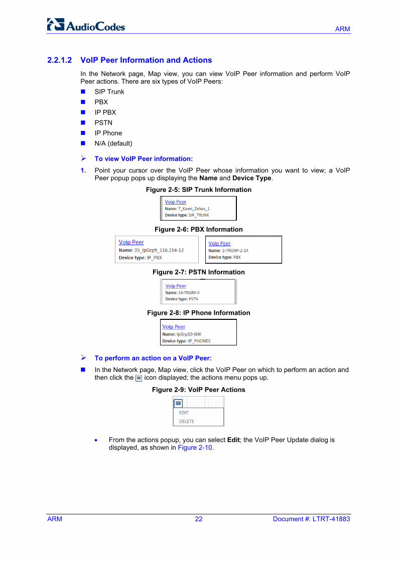
2.2.1.2 VoIP Peer Information and Actions In the Network page, Map view, you can view VoIP Peer information and perform VoIP Peer actions. There are six types of VoIP Peers: SIP Trunk PBX IP PBX PSTN IP Phone N/A (default)
To view VoIP Peer information: 1. Point your cursor over the VoIP Peer whose information you want to view; a VoIP
Peer popup pops up displaying the Name and Device Type.
Figure 2-5: SIP Trunk Information
Figure 2-6: PBX Information
Figure 2-7: PSTN Information
Figure 2-8: IP Phone Information
To perform an action on a VoIP Peer:
In the Network page, Map view, click the VoIP Peer on which to perform an action and then click the icon displayed; the actions menu pops up.
Figure 2-9: VoIP Peer Actions
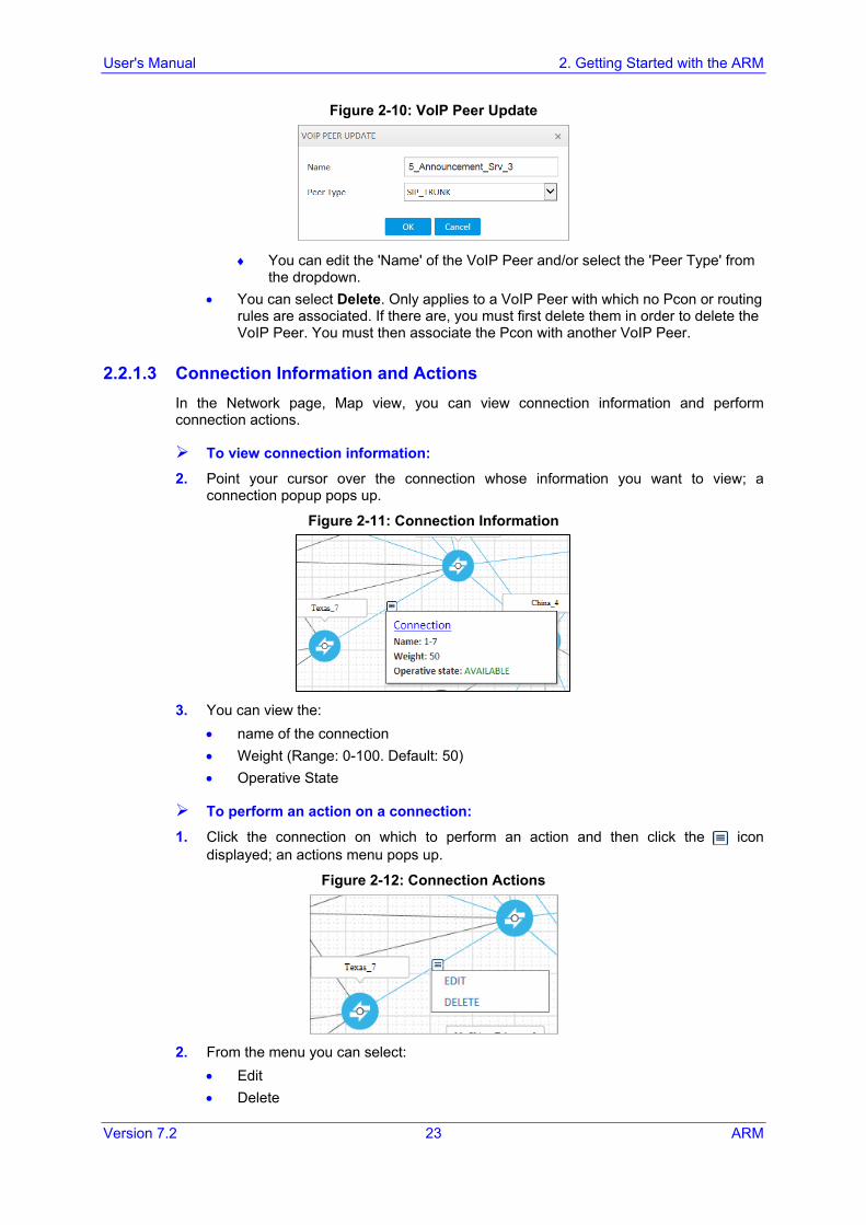
• From the actions popup, you can select Edit; the VoIP Peer Update dialog is displayed, as shown in Figure 2-10.
User's Manual 2. Getting Started with the ARM
Version 7.2 23 ARM
Figure 2-10: VoIP Peer Update
♦ You can edit the 'Name' of the VoIP Peer and/or select the 'Peer Type' from
the dropdown. • You can select Delete. Only applies to a VoIP Peer with which no Pcon or routing
rules are associated. If there are, you must first delete them in order to delete the VoIP Peer. You must then associate the Pcon with another VoIP Peer.
2.2.1.3 Connection Information and Actions In the Network page, Map view, you can view connection information and perform connection actions.
To view connection information:
2. Point your cursor over the connection whose information you want to view; a connection popup pops up.
Figure 2-11: Connection Information
3. You can view the:
• name of the connection • Weight (Range: 0-100. Default: 50) • Operative State
To perform an action on a connection:
1. Click the connection on which to perform an action and then click the icon displayed; an actions menu pops up.
Figure 2-12: Connection Actions
2. From the menu you can select:
• Edit • Delete
ARM
ARM 24 Document #: LTRT-41883
3. Select Edit; the CONNECTION DEFINITION screen opens.
Figure 2-13: CONNECTION DEFINITION
4. You can edit the:
• name of the connection • Weight (Range: 0-100. Default: 50)
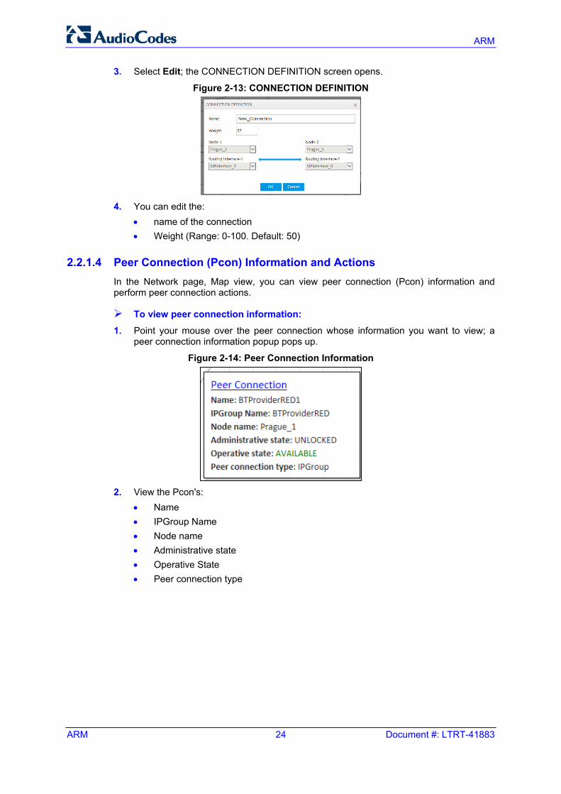
2.2.1.4 Peer Connection (Pcon) Information and Actions In the Network page, Map view, you can view peer connection (Pcon) information and perform peer connection actions.
To view peer connection information:
1. Point your mouse over the peer connection whose information you want to view; a peer connection information popup pops up.
Figure 2-14: Peer Connection Information
2. View the Pcon's:
• Name • IPGroup Name • Node name • Administrative state • Operative State • Peer connection type
User's Manual 2. Getting Started with the ARM
Version 7.2 25 ARM
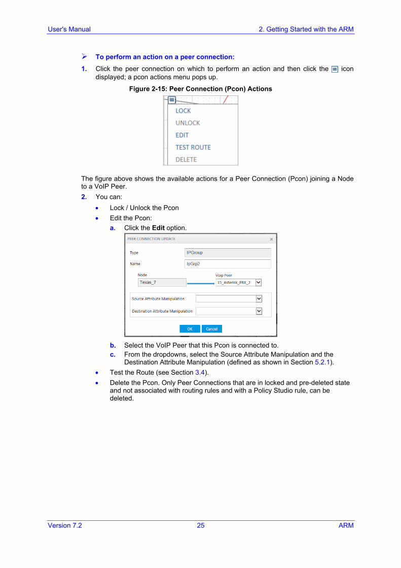
To perform an action on a peer connection:
1. Click the peer connection on which to perform an action and then click the icon displayed; a pcon actions menu pops up.
Figure 2-15: Peer Connection (Pcon) Actions
The figure above shows the available actions for a Peer Connection (Pcon) joining a Node to a VoIP Peer. 2. You can:
• Lock / Unlock the Pcon • Edit the Pcon:
a. Click the Edit option.
b. Select the VoIP Peer that this Pcon is connected to. c. From the dropdowns, select the Source Attribute Manipulation and the
Destination Attribute Manipulation (defined as shown in Section 5.2.1). • Test the Route (see Section 3.4). • Delete the Pcon. Only Peer Connections that are in locked and pre-deleted state
and not associated with routing rules and with a Policy Studio rule, can be deleted.
ARM
ARM 26 Document #: LTRT-41883
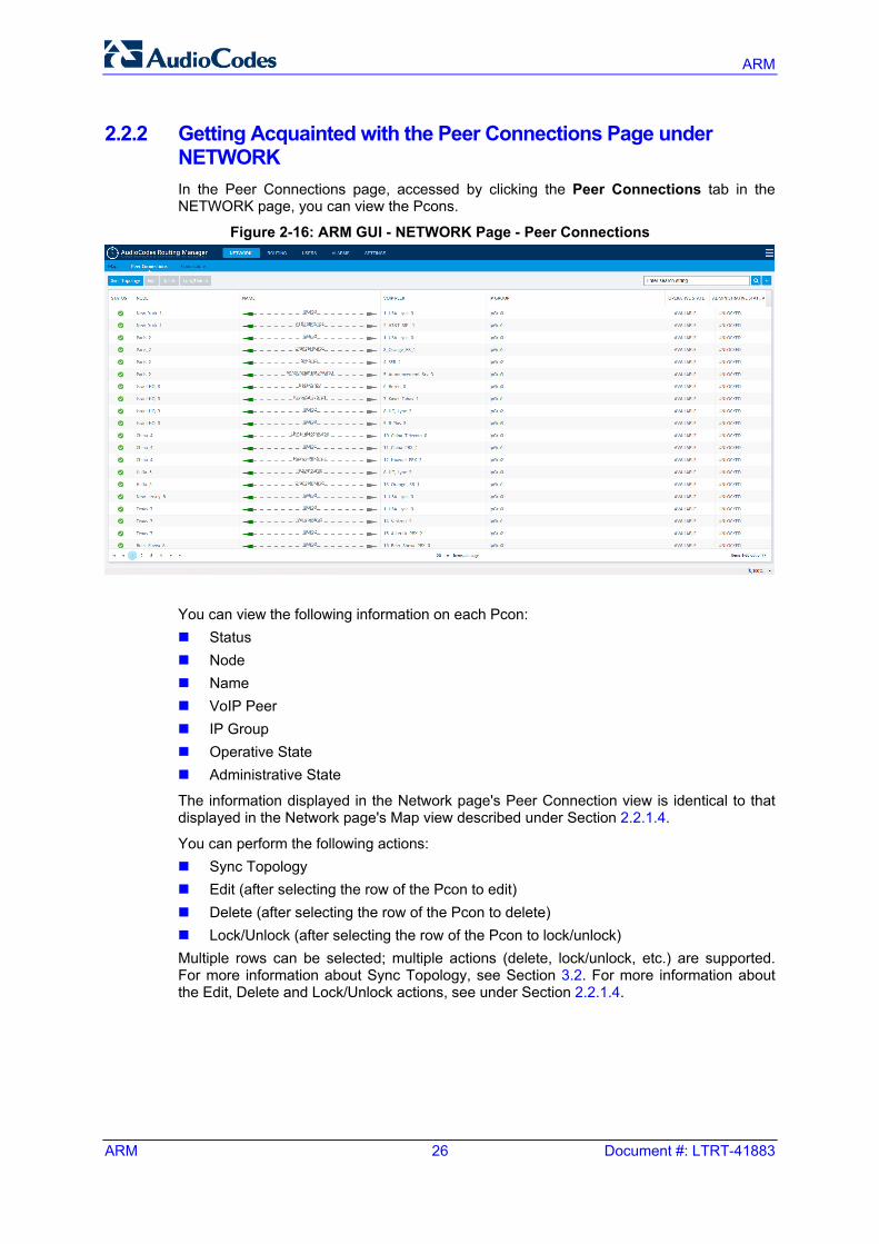
2.2.2 Getting Acquainted with the Peer Connections Page under NETWORK In the Peer Connections page, accessed by clicking the Peer Connections tab in the NETWORK page, you can view the Pcons.
Figure 2-16: ARM GUI - NETWORK Page - Peer Connections
You can view the following information on each Pcon: Status Node Name VoIP Peer IP Group Operative State Administrative State
The information displayed in the Network page's Peer Connection view is identical to that displayed in the Network page's Map view described under Section 2.2.1.4.
You can perform the following actions: Sync Topology Edit (after selecting the row of the Pcon to edit) Delete (after selecting the row of the Pcon to delete) Lock/Unlock (after selecting the row of the Pcon to lock/unlock) Multiple rows can be selected; multiple actions (delete, lock/unlock, etc.) are supported. For more information about Sync Topology, see Section 3.2. For more information about the Edit, Delete and Lock/Unlock actions, see under Section 2.2.1.4.
User's Manual 2. Getting Started with the ARM
Version 7.2 27 ARM
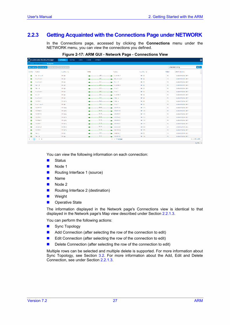
2.2.3 Getting Acquainted with the Connections Page under NETWORK In the Connections page, accessed by clicking the Connections menu under the NETWORK menu, you can view the connections you defined.
Figure 2-17: ARM GUI - Network Page - Connections View
You can view the following information on each connection: Status Node 1 Routing Interface 1 (source) Name Node 2 Routing Interface 2 (destination) Weight Operative State
The information displayed in the Network page's Connections view is identical to that displayed in the Network page's Map view described under Section 2.2.1.3.
You can perform the following actions: Sync Topology Add Connection (after selecting the row of the connection to edit) Edit Connection (after selecting the row of the connection to edit) Delete Connection (after selecting the row of the connection to edit)
Multiple rows can be selected and multiple delete is supported. For more information about Sync Topology, see Section 3.2. For more information about the Add, Edit and Delete Connection, see under Section 2.2.1.3.

ARM
ARM 28 Document #: LTRT-41883
This page is intentionally left blank.
User's Manual 3. Defining a Network
Version 7.2 29 ARM
3 Defining a Network The ARM features auto-detection capability. It automatically detects and discovers network entities, allowing you to begin defining actions immediately after auto-detection.
Note: Do not modify the SBC-level / gateway-level configuration of the connections created by the ARM. It will disrupt routing decisions/performance.
3.1 Adding Connections You can define a connection between two nodes.
To add a connection:
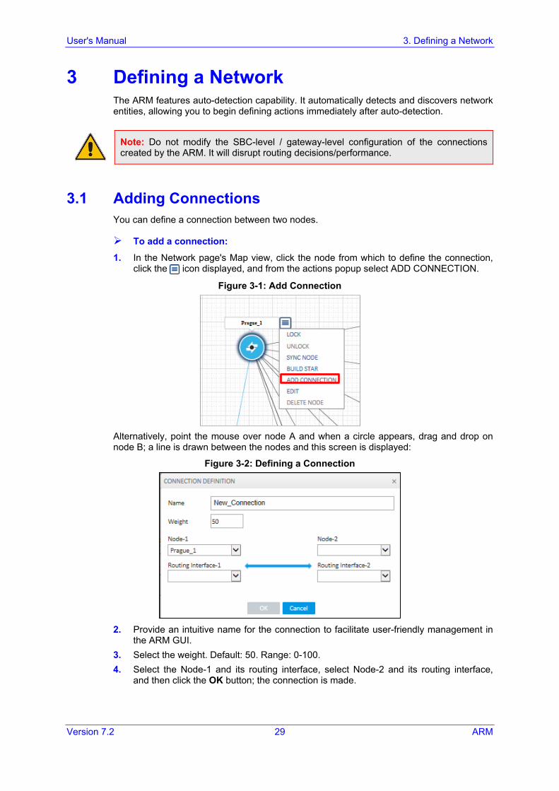
1. In the Network page's Map view, click the node from which to define the connection, click the icon displayed, and from the actions popup select ADD CONNECTION.
Figure 3-1: Add Connection
Alternatively, point the mouse over node A and when a circle appears, drag and drop on node B; a line is drawn between the nodes and this screen is displayed:
Figure 3-2: Defining a Connection
2. Provide an intuitive name for the connection to facilitate user-friendly management in
the ARM GUI. 3. Select the weight. Default: 50. Range: 0-100. 4. Select the Node-1 and its routing interface, select Node-2 and its routing interface,
and then click the OK button; the connection is made.
ARM
ARM 30 Document #: LTRT-41883
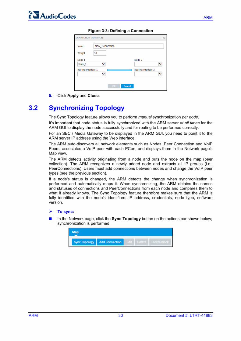
Figure 3-3: Defining a Connection
5. Click Apply and Close.
3.2 Synchronizing Topology The Sync Topology feature allows you to perform manual synchronization per node. It's important that node status is fully synchronized with the ARM server at all times for the ARM GUI to display the node successfully and for routing to be performed correctly. For an SBC / Media Gateway to be displayed in the ARM GUI, you need to point it to the ARM server IP address using the Web interface. The ARM auto-discovers all network elements such as Nodes, Peer Connection and VoIP Peers, associates a VoIP peer with each PCon, and displays them in the Network page's Map view. The ARM detects activity originating from a node and puts the node on the map (peer collection). The ARM recognizes a newly added node and extracts all IP groups (i.e., PeerConnections). Users must add connections between nodes and change the VoIP peer types (see the previous section). If a node's status is changed, the ARM detects the change when synchronization is performed and automatically maps it. When synchronizing, the ARM obtains the names and statuses of connections and PeerConnections from each node and compares them to what it already knows. The Sync Topology feature therefore makes sure that the ARM is fully identified with the node's identifiers: IP address, credentials, node type, software version.
To sync: In the Network page, click the Sync Topology button on the actions bar shown below;
synchronization is performed.
User's Manual 3. Defining a Network
Version 7.2 31 ARM
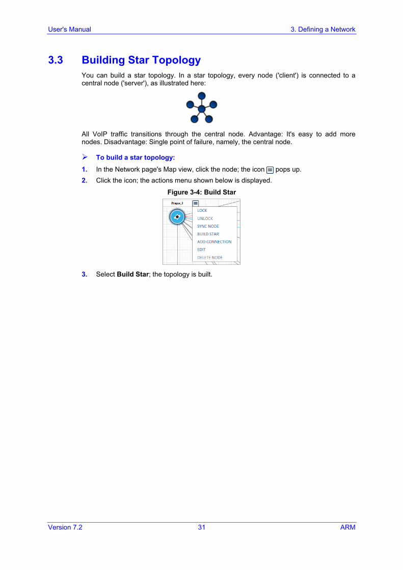
3.3 Building Star Topology You can build a star topology. In a star topology, every node ('client') is connected to a central node ('server'), as illustrated here:
All VoIP traffic transitions through the central node. Advantage: It's easy to add more nodes. Disadvantage: Single point of failure, namely, the central node.
To build a star topology:
1. In the Network page's Map view, click the node; the icon pops up. 2. Click the icon; the actions menu shown below is displayed.
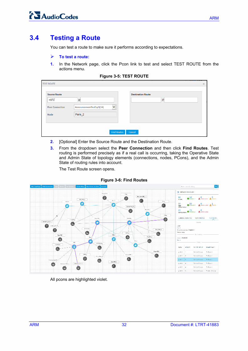
Figure 3-4: Build Star
3. Select Build Star; the topology is built.
ARM
ARM 32 Document #: LTRT-41883
3.4 Testing a Route You can test a route to make sure it performs according to expectations.
To test a route: 1. In the Network page, click the Pcon link to test and select TEST ROUTE from the
actions menu.
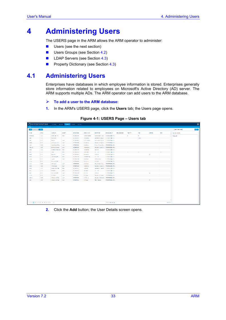
Figure 3-5: TEST ROUTE
2. [Optional] Enter the Source Route and the Destination Route. 3. From the dropdown select the Peer Connection and then click Find Routes. Test
routing is performed precisely as if a real call is occurring, taking the Operative State and Admin State of topology elements (connections, nodes, PCons), and the Admin State of routing rules into account. The Test Route screen opens.
Figure 3-6: Find Routes
All pcons are highlighted violet.
User's Manual 4. Administering Users
Version 7.2 33 ARM
4 Administering Users The USERS page in the ARM allows the ARM operator to administer: Users (see the next section) Users Groups (see Section 4.2) LDAP Servers (see Section 4.3) Property Dictionary (see Section 4.3)
4.1 Administering Users Enterprises have databases in which employee information is stored. Enterprises generally store information related to employees on Microsoft's Active Directory (AD) server. The ARM supports multiple ADs. The ARM operator can add users to the ARM database.
To add a user to the ARM database:
1. In the ARM's USERS page, click the Users tab; the Users page opens.
Figure 4-1: USERS Page – Users tab
2. Click the Add button; the User Details screen opens.
ARM
ARM 34 Document #: LTRT-41883
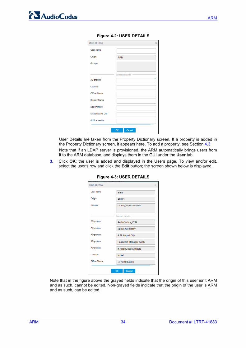
Figure 4-2: USER DETAILS
User Details are taken from the Property Dictionary screen. If a property is added in the Property Dictionary screen, it appears here. To add a property, see Section 4.3.
Note that if an LDAP server is provisioned, the ARM automatically brings users from it to the ARM database, and displays them in the GUI under the User tab. 3. Click OK; the user is added and displayed in the Users page. To view and/or edit,
select the user's row and click the Edit button; the screen shown below is displayed.
Figure 4-3: USER DETAILS
Note that in the figure above the grayed fields indicate that the origin of this user isn’t ARM and as such, cannot be edited. Non-grayed fields indicate that the origin of the user is ARM and as such, can be edited.
User's Manual 4. Administering Users
Version 7.2 35 ARM
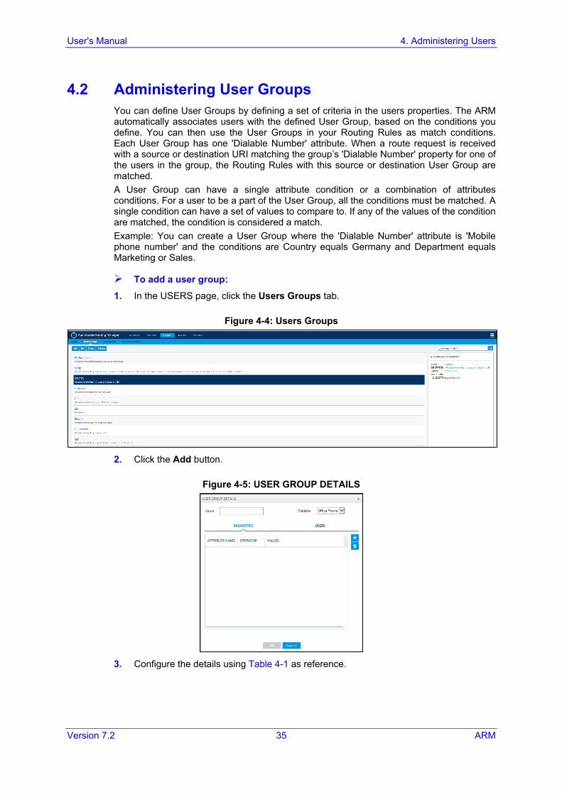
4.2 Administering User Groups You can define User Groups by defining a set of criteria in the users properties. The ARM automatically associates users with the defined User Group, based on the conditions you define. You can then use the User Groups in your Routing Rules as match conditions. Each User Group has one 'Dialable Number' attribute. When a route request is received with a source or destination URI matching the group’s 'Dialable Number' property for one of the users in the group, the Routing Rules with this source or destination User Group are matched. A User Group can have a single attribute condition or a combination of attributes conditions. For a user to be a part of the User Group, all the conditions must be matched. A single condition can have a set of values to compare to. If any of the values of the condition are matched, the condition is considered a match. Example: You can create a User Group where the 'Dialable Number' attribute is 'Mobile phone number' and the conditions are Country equals Germany and Department equals Marketing or Sales.
To add a user group:
1. In the USERS page, click the Users Groups tab.
Figure 4-4: Users Groups
2. Click the Add button.
Figure 4-5: USER GROUP DETAILS
3. Configure the details using Table 4-1 as reference.
ARM
ARM 36 Document #: LTRT-41883
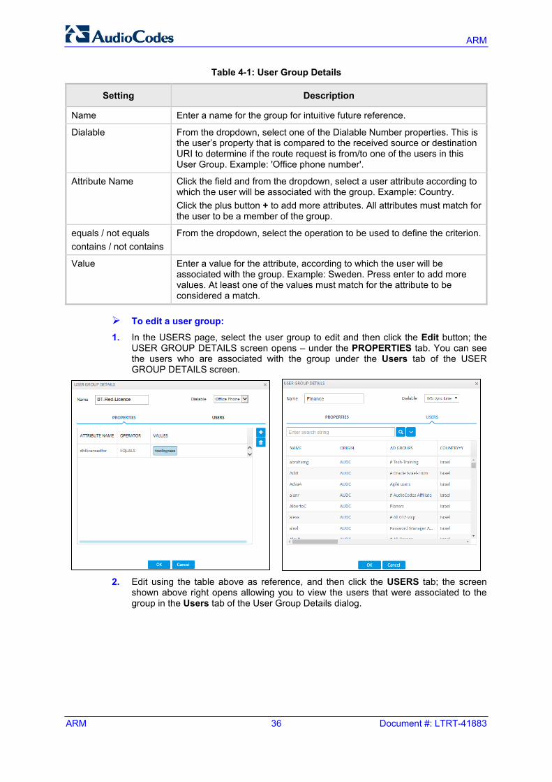
Table 4-1: User Group Details
Setting Description
Name Enter a name for the group for intuitive future reference.
Dialable From the dropdown, select one of the Dialable Number properties. This is the user’s property that is compared to the received source or destination URI to determine if the route request is from/to one of the users in this User Group. Example: 'Office phone number'.
Attribute Name Click the field and from the dropdown, select a user attribute according to which the user will be associated with the group. Example: Country. Click the plus button + to add more attributes. All attributes must match for the user to be a member of the group.
equals / not equals contains / not contains
From the dropdown, select the operation to be used to define the criterion.
Value Enter a value for the attribute, according to which the user will be associated with the group. Example: Sweden. Press enter to add more values. At least one of the values must match for the attribute to be considered a match.
To edit a user group:
1. In the USERS page, select the user group to edit and then click the Edit button; the USER GROUP DETAILS screen opens – under the PROPERTIES tab. You can see the users who are associated with the group under the Users tab of the USER GROUP DETAILS screen.
2. Edit using the table above as reference, and then click the USERS tab; the screen
shown above right opens allowing you to view the users that were associated to the group in the Users tab of the User Group Details dialog.
User's Manual 4. Administering Users
Version 7.2 37 ARM
4.3 Administering the Property Dictionary The USERS page in the ARM allows the ARM operator to administer the Property Dictionary, which is a set of all the properties that a user can have. After adding a property to the dictionary, you can add it to some or all of your LDAP servers. Properties added to an LDAP server will automatically be read from the LDAP server. Properties not added can be set locally in the ARM for each user. The Properties from the dictionary can then be used as User Group conditions as well as in in 'Policy Studio'.
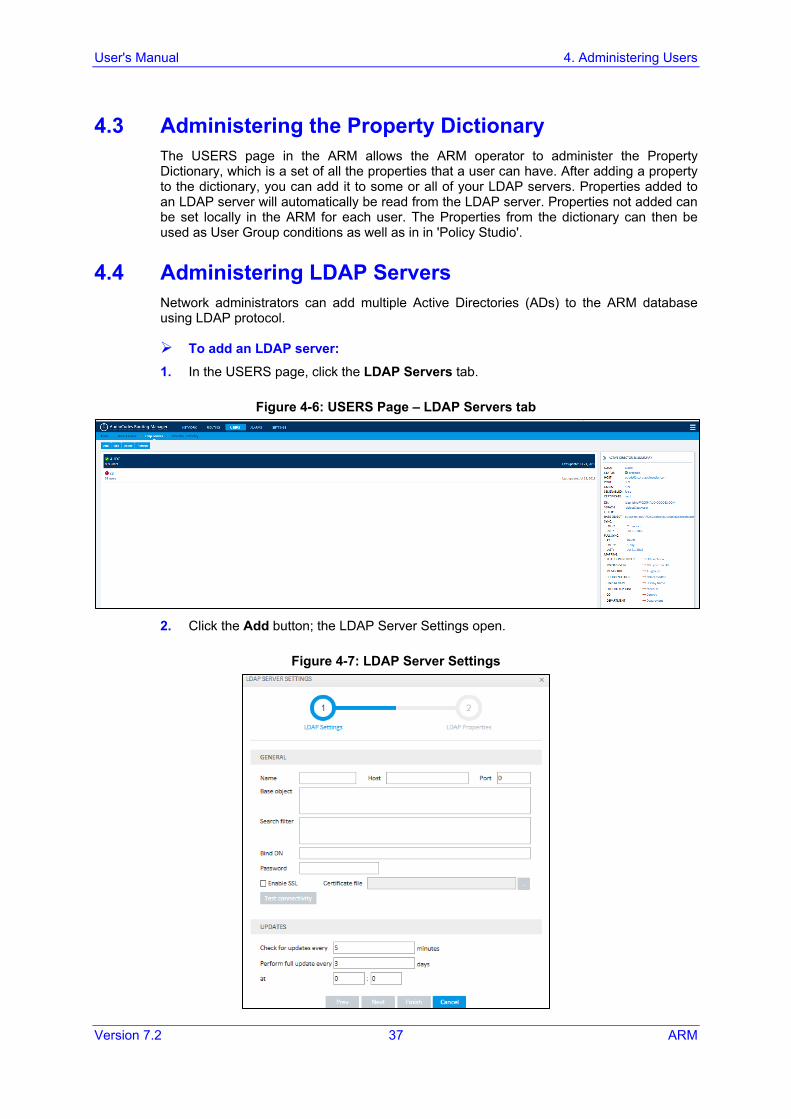
4.4 Administering LDAP Servers Network administrators can add multiple Active Directories (ADs) to the ARM database using LDAP protocol.
To add an LDAP server:
1. In the USERS page, click the LDAP Servers tab.
Figure 4-6: USERS Page – LDAP Servers tab
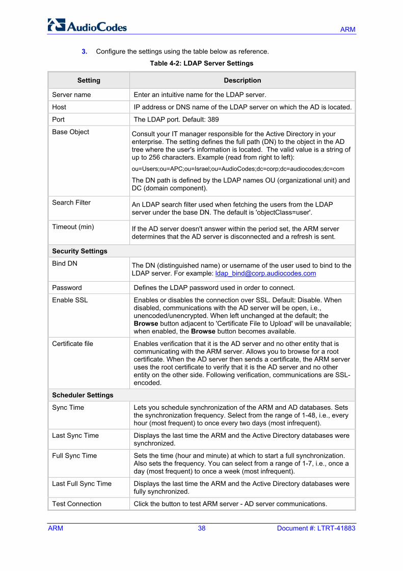
2. Click the Add button; the LDAP Server Settings open.
Figure 4-7: LDAP Server Settings
ARM
ARM 38 Document #: LTRT-41883
3. Configure the settings using the table below as reference.
Table 4-2: LDAP Server Settings
Setting Description
Server name Enter an intuitive name for the LDAP server.
Host IP address or DNS name of the LDAP server on which the AD is located.
Port The LDAP port. Default: 389
Base Object Consult your IT manager responsible for the Active Directory in your enterprise. The setting defines the full path (DN) to the object in the AD tree where the user's information is located. The valid value is a string of up to 256 characters. Example (read from right to left): ou=Users;ou=APC;ou=Israel;ou=AudioCodes;dc=corp;dc=audiocodes;dc=com
The DN path is defined by the LDAP names OU (organizational unit) and DC (domain component).
Search Filter An LDAP search filter used when fetching the users from the LDAP server under the base DN. The default is 'objectClass=user'.
Timeout (min) If the AD server doesn't answer within the period set, the ARM server determines that the AD server is disconnected and a refresh is sent.
Security Settings
Bind DN The DN (distinguished name) or username of the user used to bind to the LDAP server. For example: [email protected]
Password Defines the LDAP password used in order to connect.
Enable SSL Enables or disables the connection over SSL. Default: Disable. When disabled, communications with the AD server will be open, i.e., unencoded/unencrypted. When left unchanged at the default; the Browse button adjacent to 'Certificate File to Upload' will be unavailable; when enabled, the Browse button becomes available.
Certificate file Enables verification that it is the AD server and no other entity that is communicating with the ARM server. Allows you to browse for a root certificate. When the AD server then sends a certificate, the ARM server uses the root certificate to verify that it is the AD server and no other entity on the other side. Following verification, communications are SSL-encoded.
Scheduler Settings
Sync Time Lets you schedule synchronization of the ARM and AD databases. Sets the synchronization frequency. Select from the range of 1-48, i.e., every hour (most frequent) to once every two days (most infrequent).
Last Sync Time Displays the last time the ARM and the Active Directory databases were synchronized.
Full Sync Time Sets the time (hour and minute) at which to start a full synchronization. Also sets the frequency. You can select from a range of 1-7, i.e., once a day (most frequent) to once a week (most infrequent).
Last Full Sync Time Displays the last time the ARM and the Active Directory databases were fully synchronized.
Test Connection Click the button to test ARM server - AD server communications.
User's Manual 4. Administering Users
Version 7.2 39 ARM
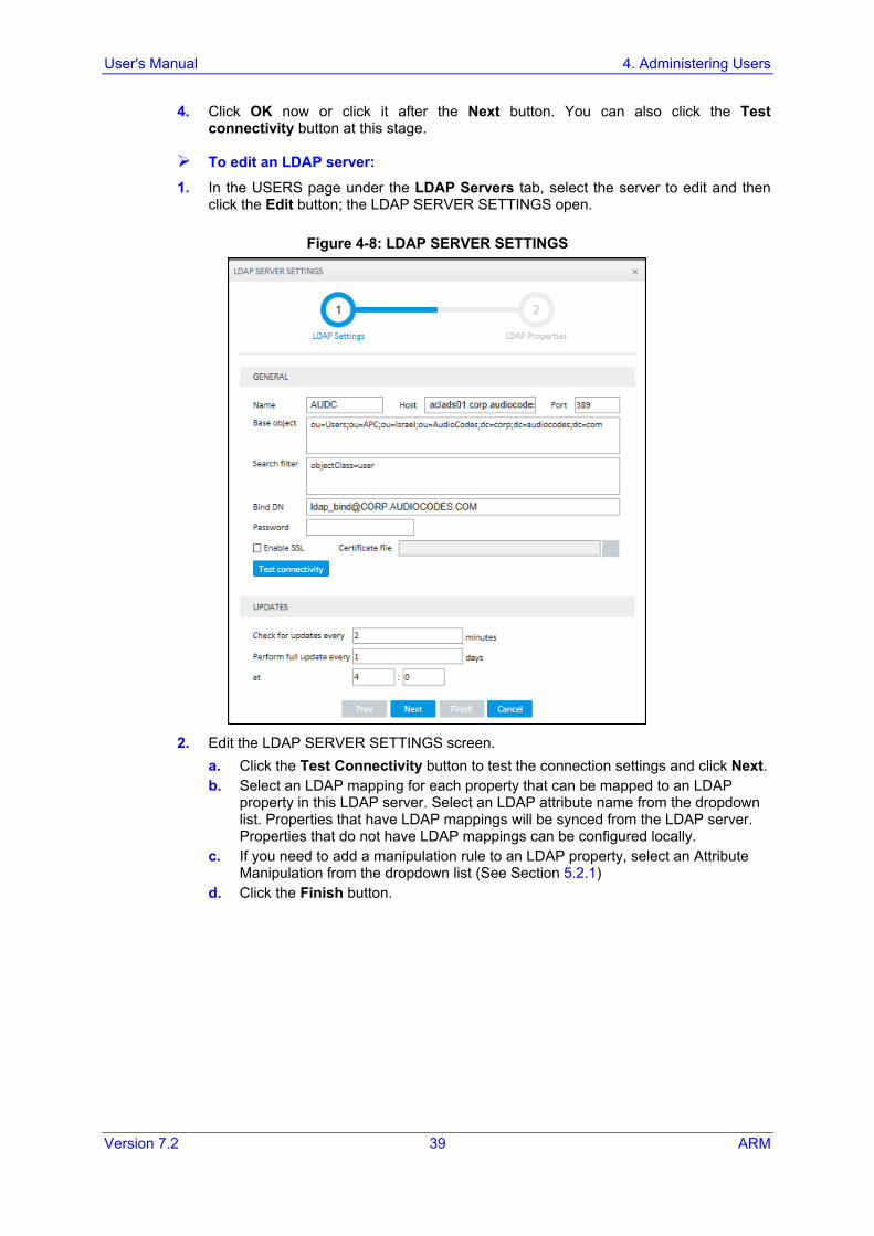
4. Click OK now or click it after the Next button. You can also click the Test connectivity button at this stage.
To edit an LDAP server: 1. In the USERS page under the LDAP Servers tab, select the server to edit and then
click the Edit button; the LDAP SERVER SETTINGS open.
Figure 4-8: LDAP SERVER SETTINGS
2. Edit the LDAP SERVER SETTINGS screen.
a. Click the Test Connectivity button to test the connection settings and click Next. b. Select an LDAP mapping for each property that can be mapped to an LDAP
property in this LDAP server. Select an LDAP attribute name from the dropdown list. Properties that have LDAP mappings will be synced from the LDAP server. Properties that do not have LDAP mappings can be configured locally.
c. If you need to add a manipulation rule to an LDAP property, select an Attribute Manipulation from the dropdown list (See Section 5.2.1)
d. Click the Finish button.
ARM
ARM 40 Document #: LTRT-41883
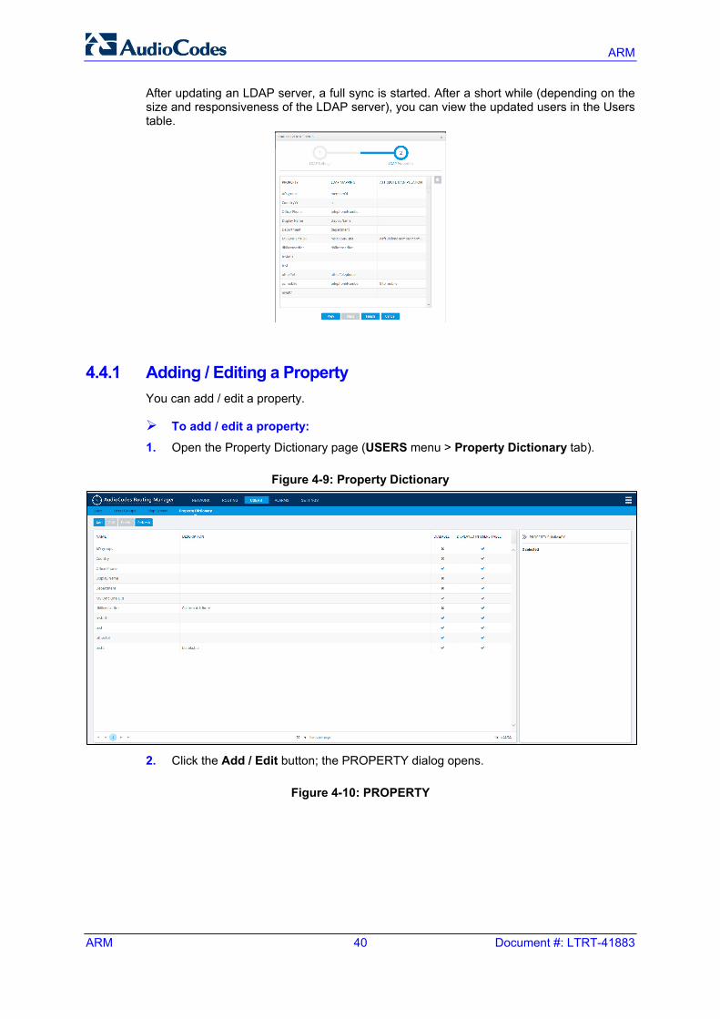
After updating an LDAP server, a full sync is started. After a short while (depending on the size and responsiveness of the LDAP server), you can view the updated users in the Users table.
4.4.1 Adding / Editing a Property You can add / edit a property.
To add / edit a property:
1. Open the Property Dictionary page (USERS menu > Property Dictionary tab).
Figure 4-9: Property Dictionary
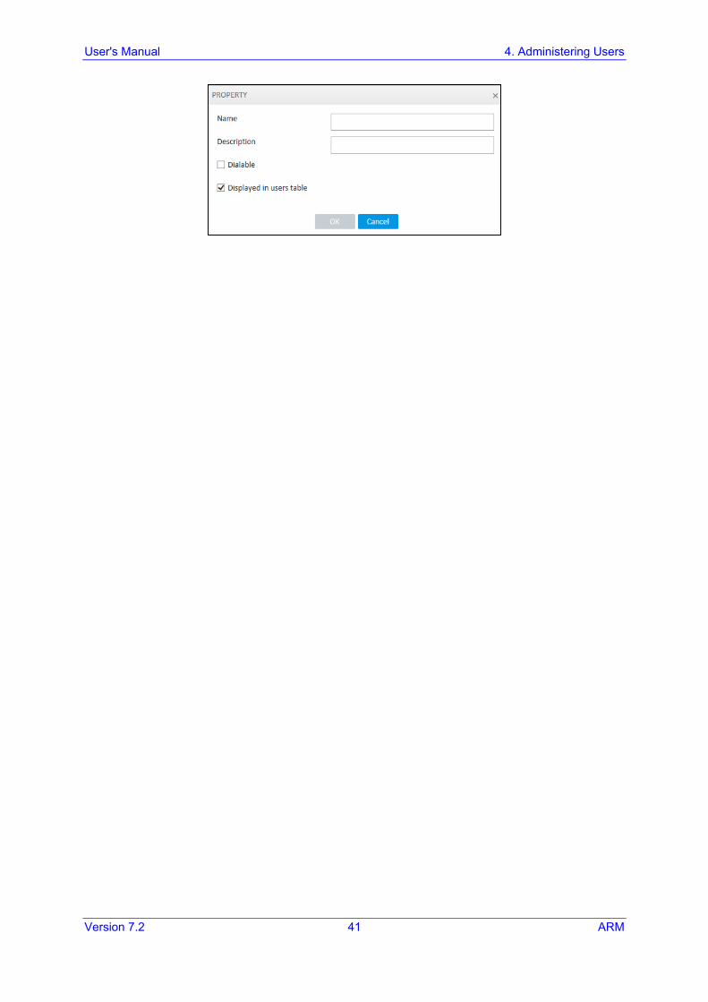
2. Click the Add / Edit button; the PROPERTY dialog opens.
Figure 4-10: PROPERTY
User's Manual 4. Administering Users
Version 7.2 41 ARM
ARM
ARM 42 Document #: LTRT-41883
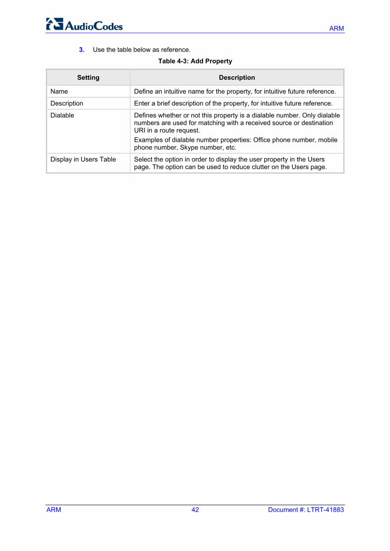
3. Use the table below as reference.
Table 4-3: Add Property
Setting Description
Name Define an intuitive name for the property, for intuitive future reference.
Description Enter a brief description of the property, for intuitive future reference.
Dialable Defines whether or not this property is a dialable number. Only dialable numbers are used for matching with a received source or destination URI in a route request. Examples of dialable number properties: Office phone number, mobile phone number, Skype number, etc.
Display in Users Table Select the option in order to display the user property in the Users page. The option can be used to reduce clutter on the Users page.
User's Manual 5. Configuring Settings
Version 7.2 43 ARM
5 Configuring Settings The SETTINGS page (under the SETTINGS menu) lets you Configure Network Services
• Syslog server (see Section 5.1.1) • NTP server (see Section 5.1.2
Configure Call Flow • Attribute Manipulation (see Section 5.2.1) • Prefix Groups (see Section 5.2.2) • Number Manipulation (see Section 5.2.3 • Policy Studio (see Section 5.2.4) • Routing (see Section 5.2.5)
Perform Administration • Software License (see Section 5.3.1) • Security (see Section 5.3.2) • Operators (see Section 5.3.3)
Add/Edit Routing Servers (see Section 5.4)
5.1 Configuring Network Services This section shows how to edit a syslog server and add/edit an NTP server.
5.1.1 Editing a Syslog Server This section shows how to edit a Syslog Server.
To edit a Syslog Server:
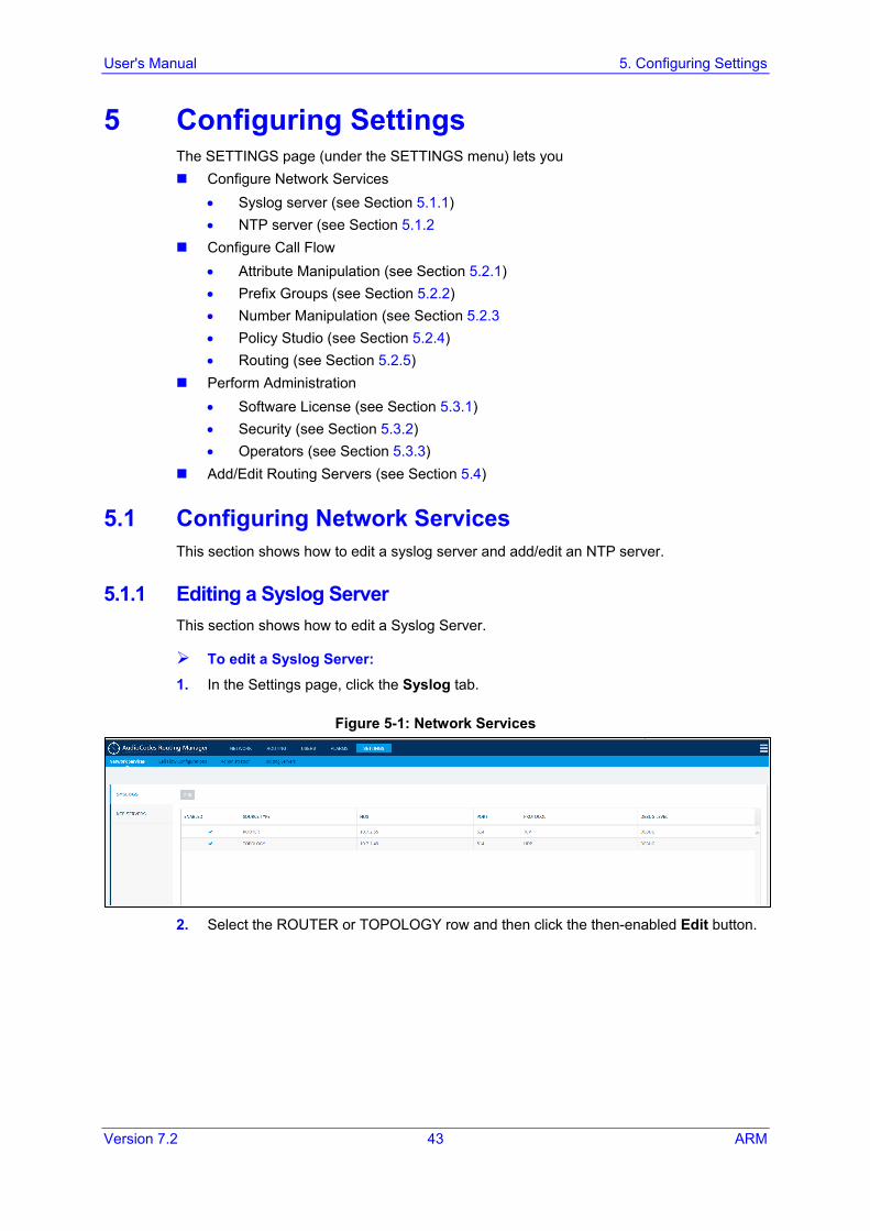
1. In the Settings page, click the Syslog tab.
Figure 5-1: Network Services
2. Select the ROUTER or TOPOLOGY row and then click the then-enabled Edit button.
ARM
ARM 44 Document #: LTRT-41883
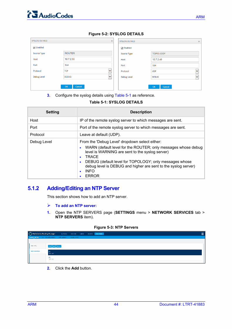
Figure 5-2: SYSLOG DETAILS
3. Configure the syslog details using Table 5-1 as reference.
Table 5-1: SYSLOG DETAILS
Setting Description
Host IP of the remote syslog server to which messages are sent.
Port Port of the remote syslog server to which messages are sent.
Protocol Leave at default (UDP).
Debug Level From the 'Debug Level' dropdown select either: • WARN (default level for the ROUTER; only messages whose debug
level is WARNING are sent to the syslog server) • TRACE • DEBUG (default level for TOPOLOGY; only messages whose
debug level is DEBUG and higher are sent to the syslog server) • INFO • ERROR
5.1.2 Adding/Editing an NTP Server This section shows how to add an NTP server.
To add an NTP server: 1. Open the NTP SERVERS page (SETTINGS menu > NETWORK SERVICES tab >
NTP SERVERS item).
Figure 5-3: NTP Servers
2. Click the Add button.
User's Manual 5. Configuring Settings
Version 7.2 45 ARM
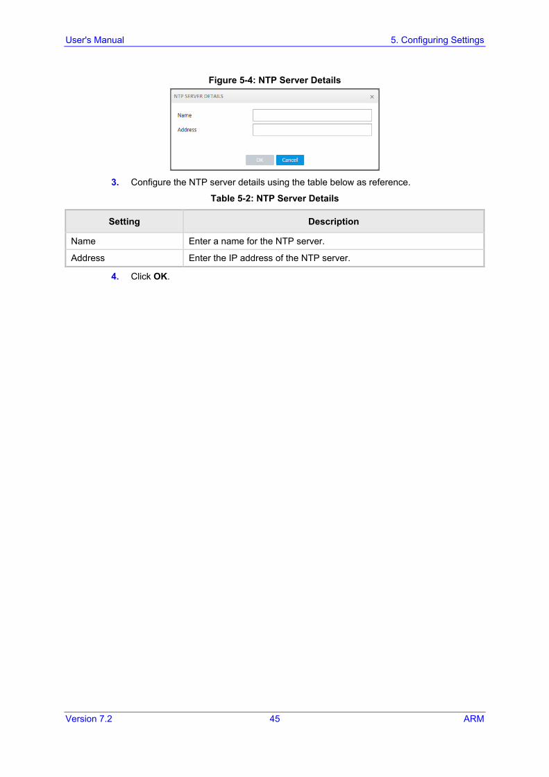
Figure 5-4: NTP Server Details
3. Configure the NTP server details using the table below as reference.
Table 5-2: NTP Server Details
Setting Description
Name Enter a name for the NTP server.
Address Enter the IP address of the NTP server.
4. Click OK.
ARM
ARM 46 Document #: LTRT-41883
5.2 Configuring Call Flow
5.2.1 Adding an Attribute Manipulation Group You can add an Attribute Manipulation Group.
To add an Attribute Manipulation Group:
1. Open the ATTRIBUTE MANIPULATION page (SETTINGS menu > Call Flow Configurations tab > Manipulation Definition).
Figure 5-5: Attribute Manipulation
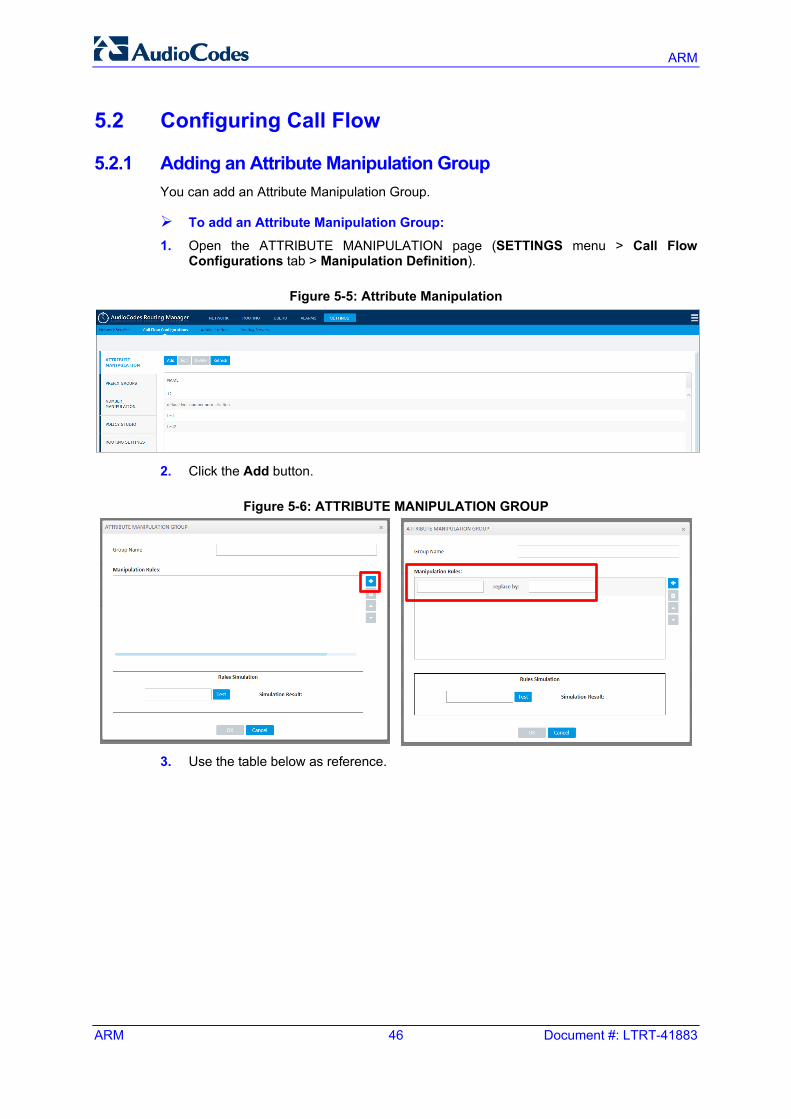
2. Click the Add button.
Figure 5-6: ATTRIBUTE MANIPULATION GROUP
3. Use the table below as reference.
User's Manual 5. Configuring Settings
Version 7.2 47 ARM
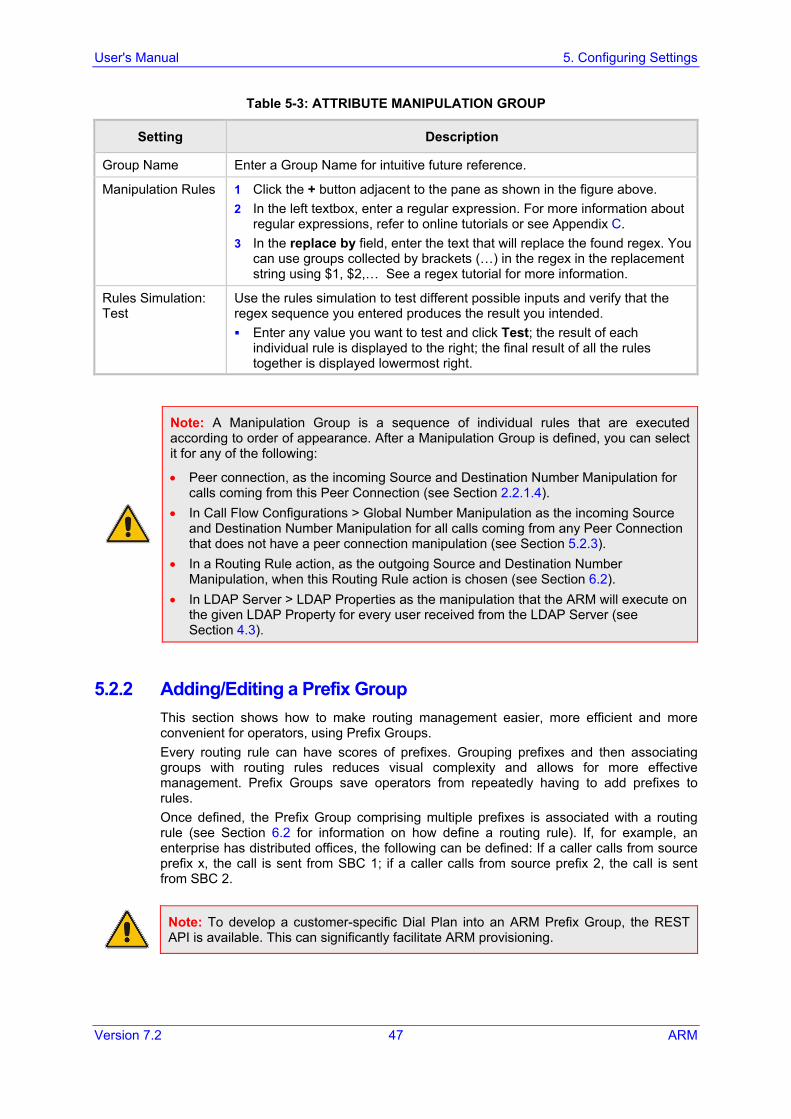
Table 5-3: ATTRIBUTE MANIPULATION GROUP
Setting Description
Group Name Enter a Group Name for intuitive future reference.
Manipulation Rules 1 Click the + button adjacent to the pane as shown in the figure above. 2 In the left textbox, enter a regular expression. For more information about
regular expressions, refer to online tutorials or see Appendix C. 3 In the replace by field, enter the text that will replace the found regex. You
can use groups collected by brackets (…) in the regex in the replacement string using $1, $2,… See a regex tutorial for more information.
Rules Simulation: Test
Use the rules simulation to test different possible inputs and verify that the regex sequence you entered produces the result you intended. Enter any value you want to test and click Test; the result of each
individual rule is displayed to the right; the final result of all the rules together is displayed lowermost right.
Note: A Manipulation Group is a sequence of individual rules that are executed according to order of appearance. After a Manipulation Group is defined, you can select it for any of the following:
• Peer connection, as the incoming Source and Destination Number Manipulation for calls coming from this Peer Connection (see Section 2.2.1.4).
• In Call Flow Configurations > Global Number Manipulation as the incoming Source and Destination Number Manipulation for all calls coming from any Peer Connection that does not have a peer connection manipulation (see Section 5.2.3).
• In a Routing Rule action, as the outgoing Source and Destination Number Manipulation, when this Routing Rule action is chosen (see Section 6.2).
• In LDAP Server > LDAP Properties as the manipulation that the ARM will execute on the given LDAP Property for every user received from the LDAP Server (see Section 4.3).
5.2.2 Adding/Editing a Prefix Group This section shows how to make routing management easier, more efficient and more convenient for operators, using Prefix Groups. Every routing rule can have scores of prefixes. Grouping prefixes and then associating groups with routing rules reduces visual complexity and allows for more effective management. Prefix Groups save operators from repeatedly having to add prefixes to rules. Once defined, the Prefix Group comprising multiple prefixes is associated with a routing rule (see Section 6.2 for information on how define a routing rule). If, for example, an enterprise has distributed offices, the following can be defined: If a caller calls from source prefix x, the call is sent from SBC 1; if a caller calls from source prefix 2, the call is sent from SBC 2.
Note: To develop a customer-specific Dial Plan into an ARM Prefix Group, the REST API is available. This can significantly facilitate ARM provisioning.
ARM
ARM 48 Document #: LTRT-41883
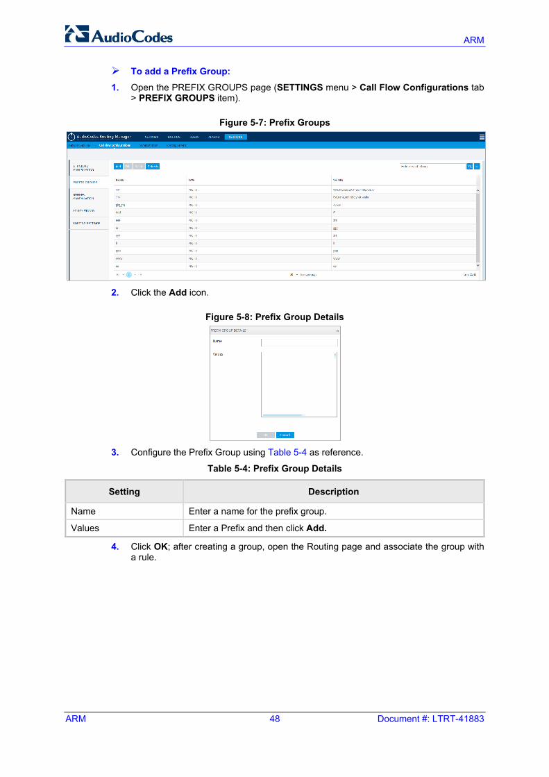
To add a Prefix Group:
1. Open the PREFIX GROUPS page (SETTINGS menu > Call Flow Configurations tab > PREFIX GROUPS item).
Figure 5-7: Prefix Groups
2. Click the Add icon.
Figure 5-8: Prefix Group Details
3. Configure the Prefix Group using Table 5-4 as reference.
Table 5-4: Prefix Group Details
Setting Description
Name Enter a name for the prefix group.
Values Enter a Prefix and then click Add.
4. Click OK; after creating a group, open the Routing page and associate the group with a rule.
User's Manual 5. Configuring Settings
Version 7.2 49 ARM
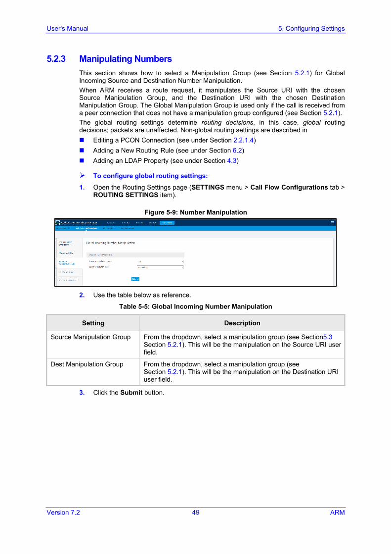
5.2.3 Manipulating Numbers This section shows how to select a Manipulation Group (see Section 5.2.1) for Global Incoming Source and Destination Number Manipulation. When ARM receives a route request, it manipulates the Source URI with the chosen Source Manipulation Group, and the Destination URI with the chosen Destination Manipulation Group. The Global Manipulation Group is used only if the call is received from a peer connection that does not have a manipulation group configured (see Section 5.2.1). The global routing settings determine routing decisions, in this case, global routing decisions; packets are unaffected. Non-global routing settings are described in Editing a PCON Connection (see under Section 2.2.1.4) Adding a New Routing Rule (see under Section 6.2) Adding an LDAP Property (see under Section 4.3)
To configure global routing settings: 1. Open the Routing Settings page (SETTINGS menu > Call Flow Configurations tab >
ROUTING SETTINGS item).
Figure 5-9: Number Manipulation
2. Use the table below as reference.
Table 5-5: Global Incoming Number Manipulation
Setting Description
Source Manipulation Group From the dropdown, select a manipulation group (see Section 5.3 Section 5.2.1). This will be the manipulation on the Source URI user field.
Dest Manipulation Group From the dropdown, select a manipulation group (see Section 5.2.1). This will be the manipulation on the Destination URI user field.
3. Click the Submit button.
ARM
ARM 50 Document #: LTRT-41883
5.2.4 Policy Studio This feature allows adding information to route requests that is not contained in the route requests but is taken from the user table. To accomplish this with legacy products without ARM, the LDAP server must be queried for every call using complex query rules, creating delays and straining the server. In the ARM, the user table is loaded to memory and information gathering is handled internally in real time. Policy Studio Use Examples: Each user has an internal 4-digit extension and an unrelated external phone number.
When a user makes a call outside the enterprise, the source number, i.e., the user's extension, must be replaced with their external number. When a call comes in from outside, the external number must be replaced with the user’s extension.
Same as the previous example but, in addition, there can be more than one user with the same extension, and what differentiates them is their hostname. The ARM can locate the user based on a combination of the extension and hostname attributes.
Policy Studio is a set of rules. Each rule contains a match condition and an action. The match condition is a set of route request fields to be compared, and a set of user properties to be compared to. The match condition also has a source node or pcon or set of source nodes or pcons. The action is a set of route request or response fields to be replaced, and a set of user fields to replace them with. For every route request received, the ARM processes all the rules from top to bottom. For each, the ARM searches in the users table for a user that matches all of the fields. If a user is not found, the ARM proceeds to the next rule. If a user is found, the ARM stops parsing the rules and performs the action in this rule. The action is to replace all of the listed fields with the properties of the user, as configured.
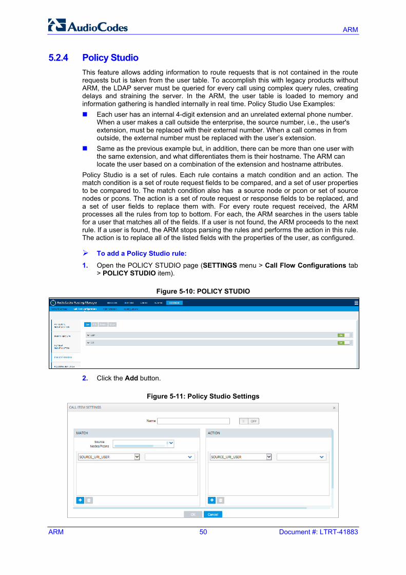
To add a Policy Studio rule:
1. Open the POLICY STUDIO page (SETTINGS menu > Call Flow Configurations tab > POLICY STUDIO item).
Figure 5-10: POLICY STUDIO
2. Click the Add button.
Figure 5-11: Policy Studio Settings
User's Manual 5. Configuring Settings
Version 7.2 51 ARM
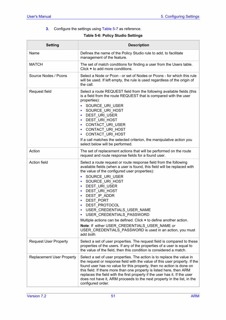
3. Configure the settings using Table 5-7 as reference.
Table 5-6: Policy Studio Settings
Setting Description
Name Defines the name of the Policy Studio rule to add, to facilitate management of the feature.
MATCH The set of match conditions for finding a user from the Users table. Click + to add more conditions.
Source Nodes / Pcons Select a Node or Pcon - or set of Nodes or Pcons - for which this rule will be used. If left empty, the rule is used regardless of the origin of the call.
Request field Select a route REQUEST field from the following available fields (this is a field from the route REQUEST that is compared with the user properties): SOURCE_URI_USER SOURCE_URI_HOST DEST_URI_USER DEST_URI_HOST CONTACT_URI_USER CONTACT_URI_HOST CONTACT_URI_HOST If a call matches the selected criterion, the manipulative action you select below will be performed.
Action The set of replacement actions that will be performed on the route request and route response fields for a found user.
Action field Select a route request or route response field from the following available fields (when a user is found, this field will be replaced with the value of the configured user properties): SOURCE_URI_USER SOURCE_URI_HOST DEST_URI_USER DEST_URI_HOST DEST_IP_ADDR DEST_PORT DEST_PROTOCOL USER_CREDENTIALS_USER_NAME USER_CREDENTIALS_PASSWORD Multiple actions can be defined. Click + to define another action. Note: If either USER_CREDENTIALS_USER_NAME or USER_CREDENTIALS_PASSWORD is used in an action, you must add both.
Request User Property Select a set of user properties. The request field is compared to these properties of the users. If any of the properties of a user is equal to the value of the field, then this condition is considered a match.
Replacement User Property Select a set of user properties. The action is to replace the value in the request or response field with the value of this user property. If the found user has no value for this property, then no action is done on this field. If there more than one property is listed here, then ARM replaces the field with the first property if the user has it. If the user does not have it, ARM proceeds to the next property in the list, in the configured order.
ARM
ARM 52 Document #: LTRT-41883
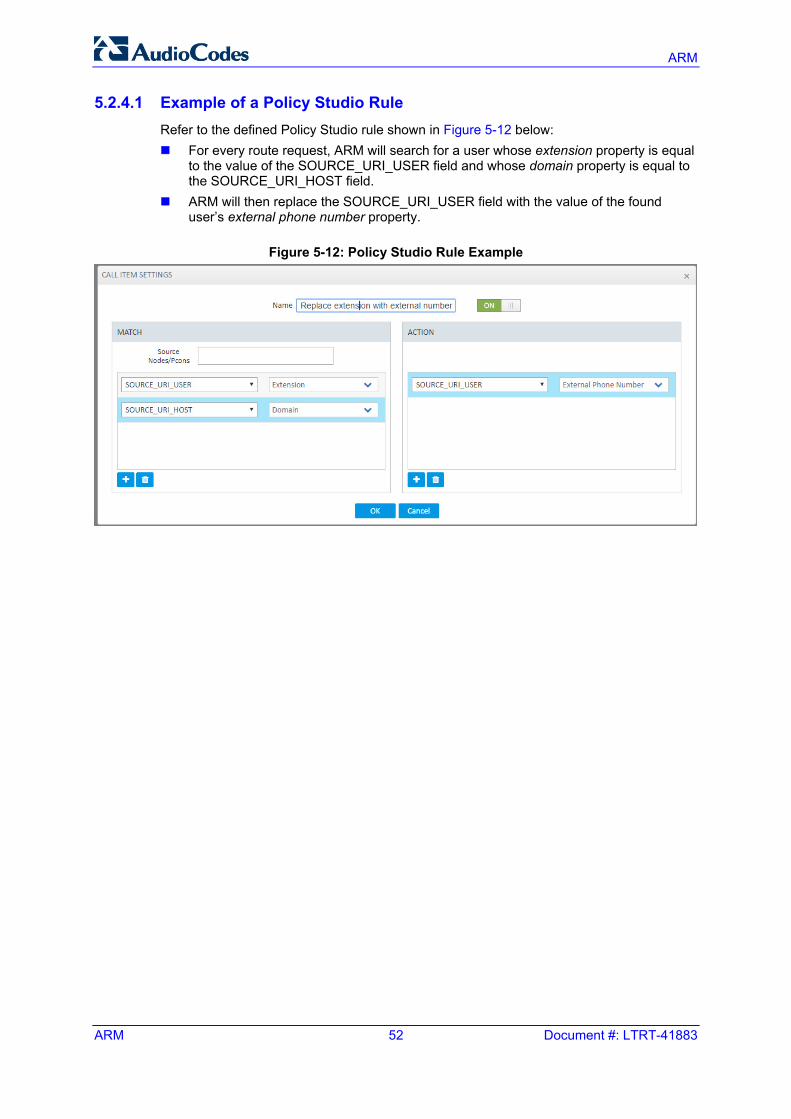
5.2.4.1 Example of a Policy Studio Rule Refer to the defined Policy Studio rule shown in Figure 5-12 below: For every route request, ARM will search for a user whose extension property is equal
to the value of the SOURCE_URI_USER field and whose domain property is equal to the SOURCE_URI_HOST field.
ARM will then replace the SOURCE_URI_USER field with the value of the found user’s external phone number property.
Figure 5-12: Policy Studio Rule Example
User's Manual 5. Configuring Settings
Version 7.2 53 ARM
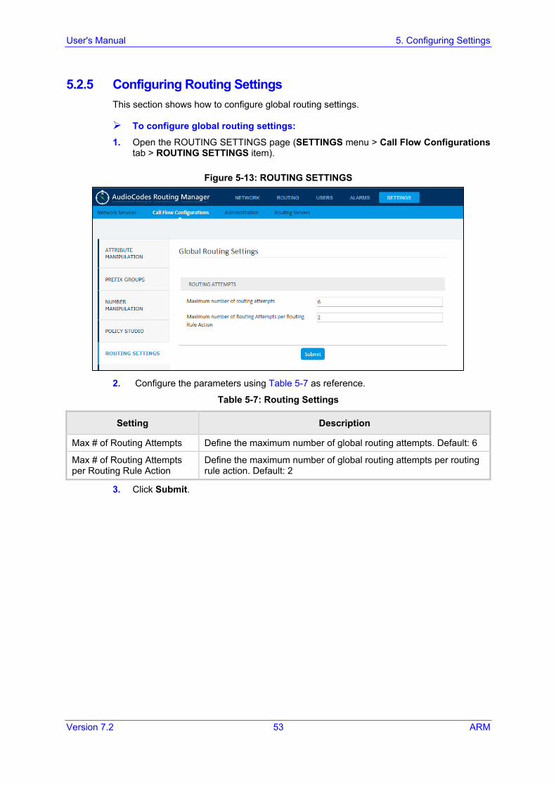
5.2.5 Configuring Routing Settings This section shows how to configure global routing settings.
To configure global routing settings:
1. Open the ROUTING SETTINGS page (SETTINGS menu > Call Flow Configurations tab > ROUTING SETTINGS item).
Figure 5-13: ROUTING SETTINGS
2. Configure the parameters using Table 5-7 as reference.
Table 5-7: Routing Settings
Setting Description
Max # of Routing Attempts Define the maximum number of global routing attempts. Default: 6
Max # of Routing Attempts per Routing Rule Action
Define the maximum number of global routing attempts per routing rule action. Default: 2
3. Click Submit.
ARM
ARM 54 Document #: LTRT-41883
5.3 Performing Administration This section shows how to perform administrative tasks: Configure a software license (see the section below) Manage security (see Section 5.3.2) Add an operator (see Section 5.3.3)
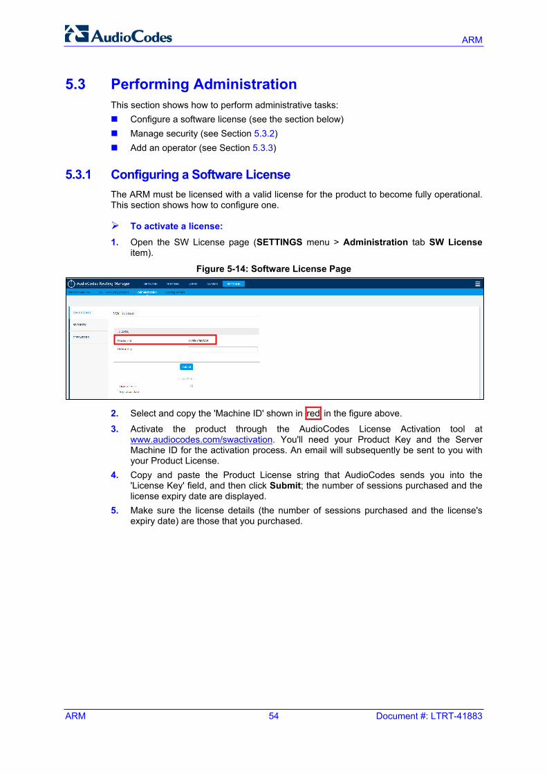
5.3.1 Configuring a Software License The ARM must be licensed with a valid license for the product to become fully operational. This section shows how to configure one.
To activate a license: 1. Open the SW License page (SETTINGS menu > Administration tab SW License
item).
Figure 5-14: Software License Page
2. Select and copy the 'Machine ID' shown in red in the figure above.
3. Activate the product through the AudioCodes License Activation tool at www.audiocodes.com/swactivation. You'll need your Product Key and the Server Machine ID for the activation process. An email will subsequently be sent to you with your Product License.
4. Copy and paste the Product License string that AudioCodes sends you into the 'License Key' field, and then click Submit; the number of sessions purchased and the license expiry date are displayed.
5. Make sure the license details (the number of sessions purchased and the license's expiry date) are those that you purchased.
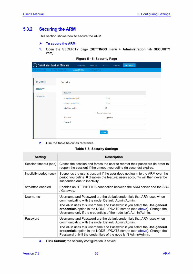
User's Manual 5. Configuring Settings
Version 7.2 55 ARM
5.3.2 Securing the ARM This section shows how to secure the ARM.
To secure the ARM:
1. Open the SECURITY page (SETTINGS menu > Administration tab SECURITY item).
Figure 5-15: Security Page
2. Use the table below as reference.
Table 5-8: Security Settings
Setting Description
Session timeout (sec) Closes the session and forces the user to reenter their password (in order to reopen the session) if the timeout you define (in seconds) expires.
Inactivity period (sec) Suspends the user's account if the user does not log in to the ARM over the period you define. 0 disables the feature; users accounts will then never be suspended due to inactivity.
http/https enabled Enables an HTTP/HTTPS connection between the ARM server and the SBC / Gateway.
Username Username and Password are the default credentials that ARM uses when communicating with the node. Default: Admin/Admin. The ARM uses this Username and Password if you select the Use general credentials option in the NODE UPDATE screen (see above). Change the Username only if the credentials of the node isn’t Admin/Admin.
Password Username and Password are the default credentials that ARM uses when communicating with the node. Default: Admin/Admin. The ARM uses this Username and Password if you select the Use general credentials option in the NODE UPDATE screen (see above). Change the Password only if the credentials of the node isn’t Admin/Admin.
3. Click Submit; the security configuration is saved.
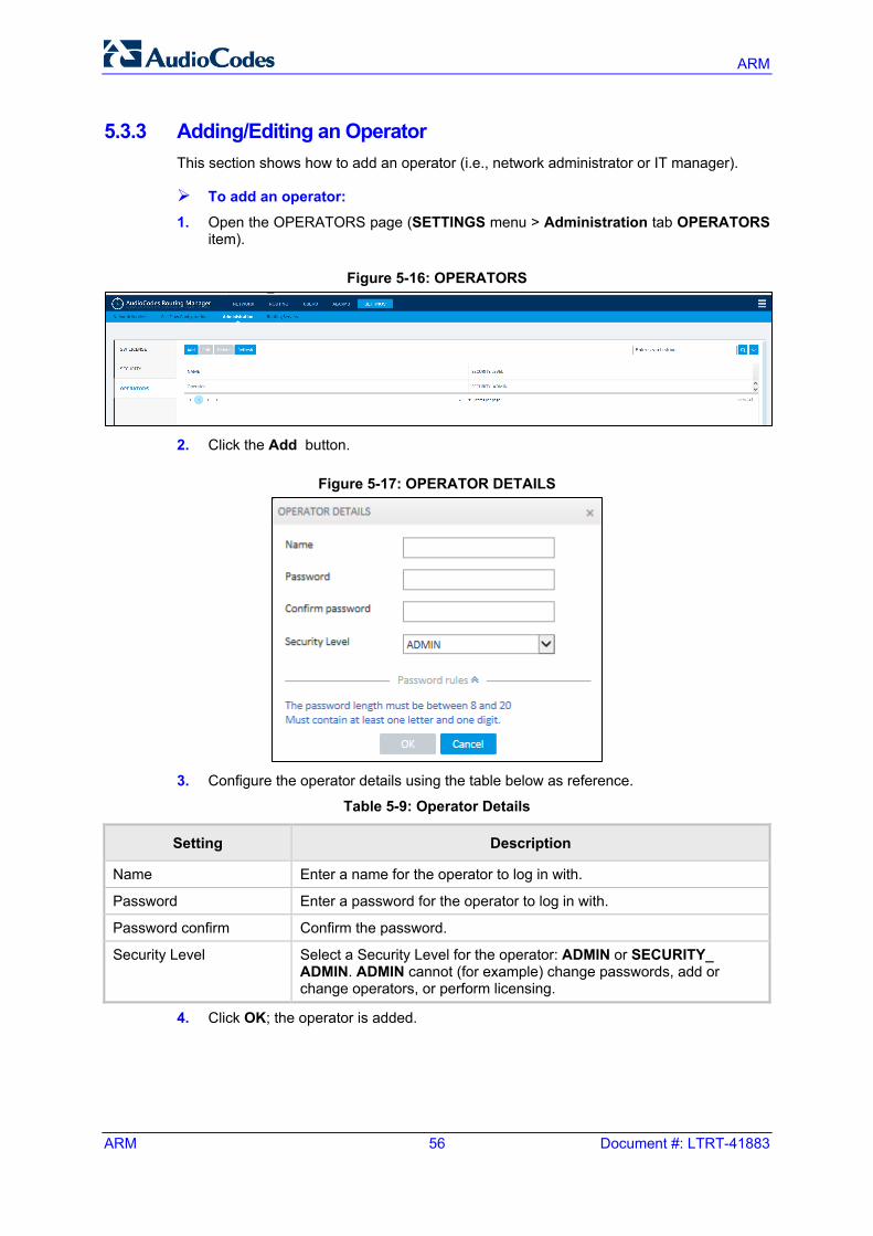
ARM
ARM 56 Document #: LTRT-41883
5.3.3 Adding/Editing an Operator This section shows how to add an operator (i.e., network administrator or IT manager).
To add an operator:
1. Open the OPERATORS page (SETTINGS menu > Administration tab OPERATORS item).
Figure 5-16: OPERATORS
2. Click the Add button.
Figure 5-17: OPERATOR DETAILS
3. Configure the operator details using the table below as reference.
Table 5-9: Operator Details
Setting Description
Name Enter a name for the operator to log in with.
Password Enter a password for the operator to log in with.
Password confirm Confirm the password.
Security Level Select a Security Level for the operator: ADMIN or SECURITY_ ADMIN. ADMIN cannot (for example) change passwords, add or change operators, or perform licensing.
4. Click OK; the operator is added.
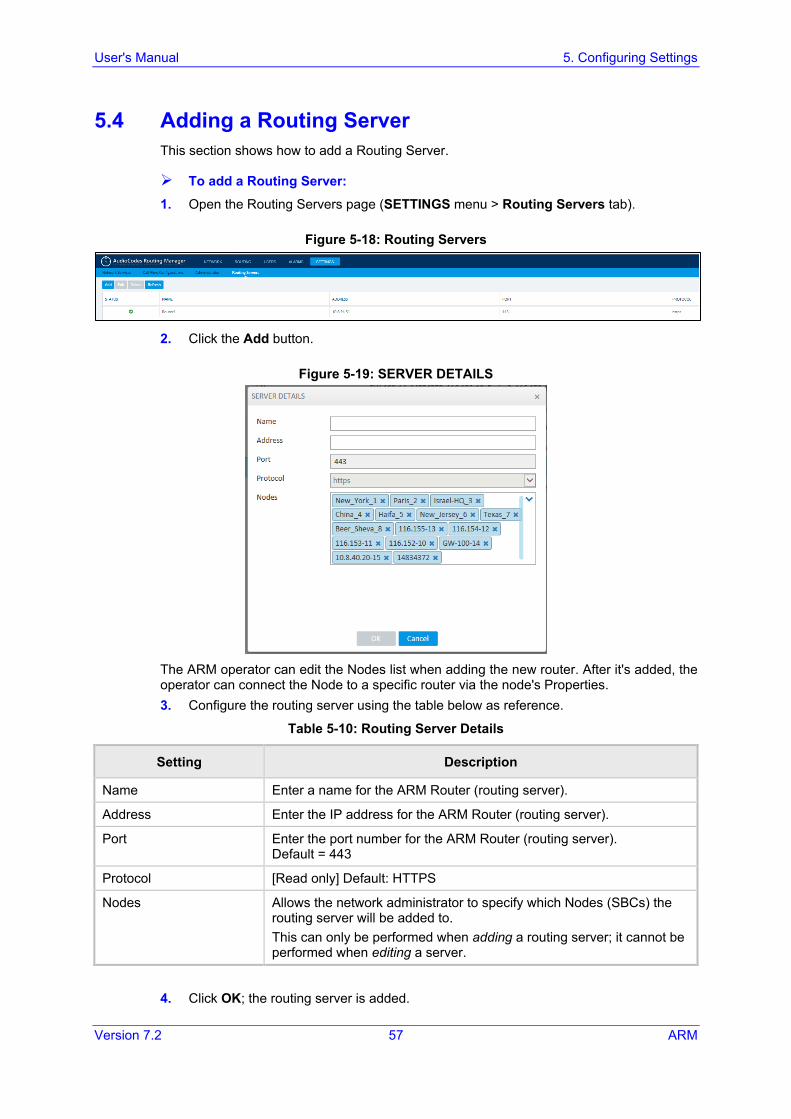
User's Manual 5. Configuring Settings
Version 7.2 57 ARM
5.4 Adding a Routing Server This section shows how to add a Routing Server.
To add a Routing Server: 1. Open the Routing Servers page (SETTINGS menu > Routing Servers tab).
Figure 5-18: Routing Servers
2. Click the Add button.
Figure 5-19: SERVER DETAILS
The ARM operator can edit the Nodes list when adding the new router. After it's added, the operator can connect the Node to a specific router via the node's Properties. 3. Configure the routing server using the table below as reference.
Table 5-10: Routing Server Details
Setting Description
Name Enter a name for the ARM Router (routing server).
Address Enter the IP address for the ARM Router (routing server).
Port Enter the port number for the ARM Router (routing server). Default = 443
Protocol [Read only] Default: HTTPS
Nodes Allows the network administrator to specify which Nodes (SBCs) the routing server will be added to. This can only be performed when adding a routing server; it cannot be performed when editing a server.
4. Click OK; the routing server is added.
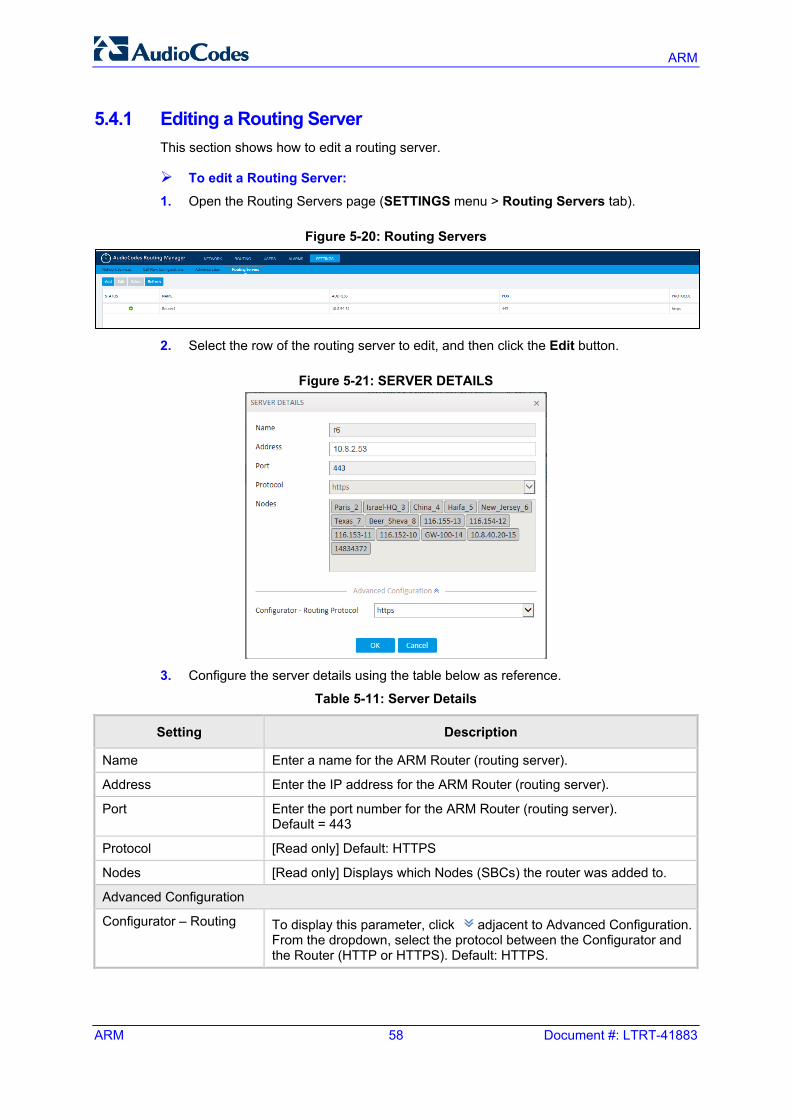
ARM
ARM 58 Document #: LTRT-41883
5.4.1 Editing a Routing Server This section shows how to edit a routing server.
To edit a Routing Server:
1. Open the Routing Servers page (SETTINGS menu > Routing Servers tab).
Figure 5-20: Routing Servers
2. Select the row of the routing server to edit, and then click the Edit button.
Figure 5-21: SERVER DETAILS
3. Configure the server details using the table below as reference.
Table 5-11: Server Details
Setting Description
Name Enter a name for the ARM Router (routing server).
Address Enter the IP address for the ARM Router (routing server).
Port Enter the port number for the ARM Router (routing server). Default = 443
Protocol [Read only] Default: HTTPS
Nodes [Read only] Displays which Nodes (SBCs) the router was added to.
Advanced Configuration
Configurator – Routing To display this parameter, click adjacent to Advanced Configuration. From the dropdown, select the protocol between the Configurator and the Router (HTTP or HTTPS). Default: HTTPS.
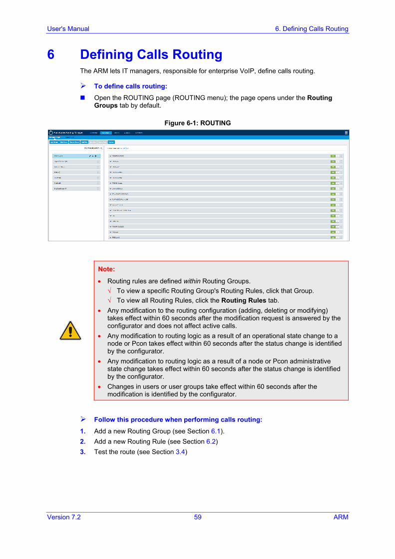
User's Manual 6. Defining Calls Routing
Version 7.2 59 ARM
6 Defining Calls Routing The ARM lets IT managers, responsible for enterprise VoIP, define calls routing.
To define calls routing:
Open the ROUTING page (ROUTING menu); the page opens under the Routing Groups tab by default.
Figure 6-1: ROUTING
Note:
• Routing rules are defined within Routing Groups. √ To view a specific Routing Group's Routing Rules, click that Group. √ To view all Routing Rules, click the Routing Rules tab.
• Any modification to the routing configuration (adding, deleting or modifying) takes effect within 60 seconds after the modification request is answered by the configurator and does not affect active calls.
• Any modification to routing logic as a result of an operational state change to a node or Pcon takes effect within 60 seconds after the status change is identified by the configurator.
• Any modification to routing logic as a result of a node or Pcon administrative state change takes effect within 60 seconds after the status change is identified by the configurator.
• Changes in users or user groups take effect within 60 seconds after the modification is identified by the configurator.
Follow this procedure when performing calls routing:
1. Add a new Routing Group (see Section 6.1). 2. Add a new Routing Rule (see Section 6.2) 3. Test the route (see Section 3.4)
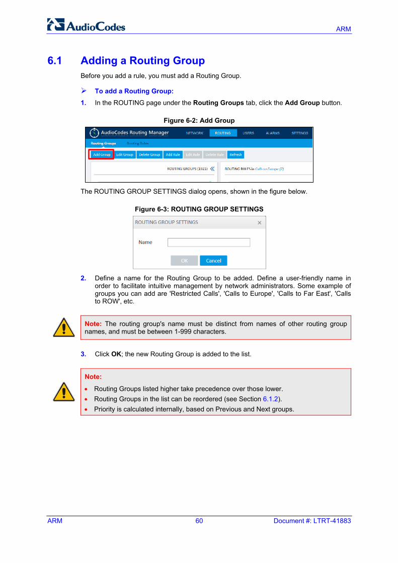
ARM
ARM 60 Document #: LTRT-41883
6.1 Adding a Routing Group Before you add a rule, you must add a Routing Group.
To add a Routing Group: 1. In the ROUTING page under the Routing Groups tab, click the Add Group button.
Figure 6-2: Add Group
The ROUTING GROUP SETTINGS dialog opens, shown in the figure below.
Figure 6-3: ROUTING GROUP SETTINGS
2. Define a name for the Routing Group to be added. Define a user-friendly name in
order to facilitate intuitive management by network administrators. Some example of groups you can add are 'Restricted Calls', 'Calls to Europe', 'Calls to Far East', 'Calls to ROW', etc.
Note: The routing group's name must be distinct from names of other routing group names, and must be between 1-999 characters.
3. Click OK; the new Routing Group is added to the list.
Note:
• Routing Groups listed higher take precedence over those lower. • Routing Groups in the list can be reordered (see Section 6.1.2). • Priority is calculated internally, based on Previous and Next groups.
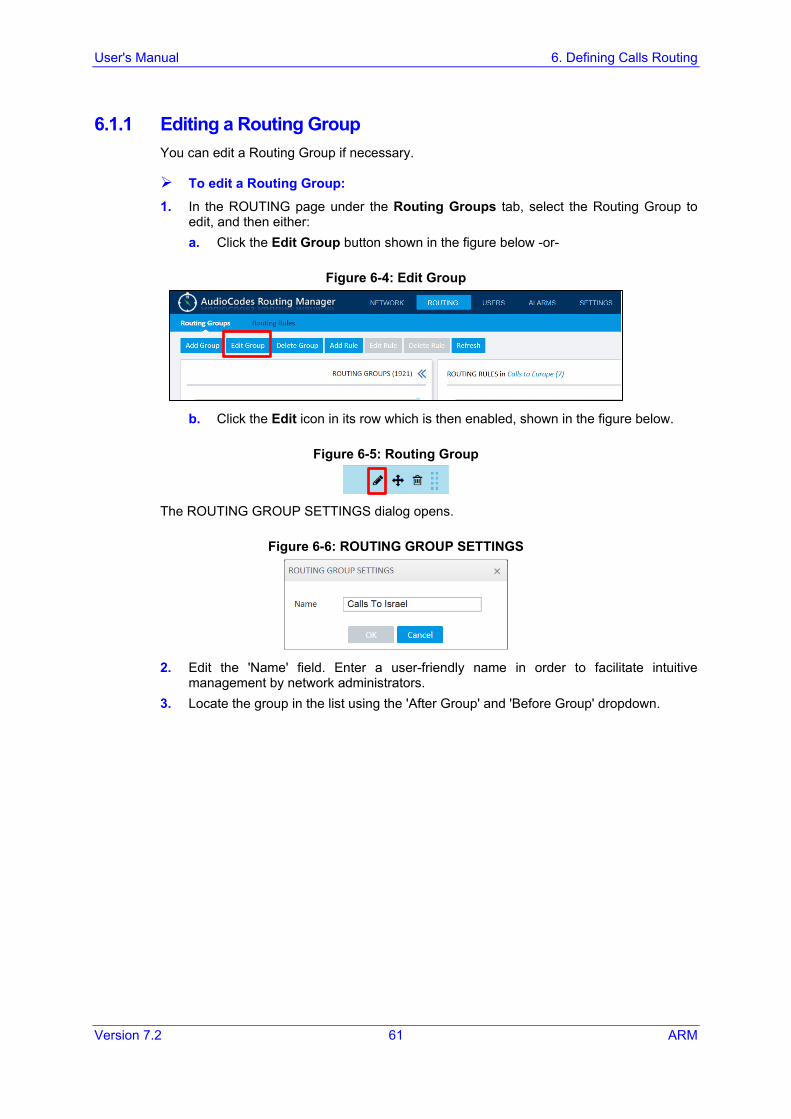
User's Manual 6. Defining Calls Routing
Version 7.2 61 ARM
6.1.1 Editing a Routing Group You can edit a Routing Group if necessary.
To edit a Routing Group:
1. In the ROUTING page under the Routing Groups tab, select the Routing Group to edit, and then either: a. Click the Edit Group button shown in the figure below -or-
Figure 6-4: Edit Group
b. Click the Edit icon in its row which is then enabled, shown in the figure below.
Figure 6-5: Routing Group
The ROUTING GROUP SETTINGS dialog opens.
Figure 6-6: ROUTING GROUP SETTINGS
2. Edit the 'Name' field. Enter a user-friendly name in order to facilitate intuitive
management by network administrators. 3. Locate the group in the list using the 'After Group' and 'Before Group' dropdown.
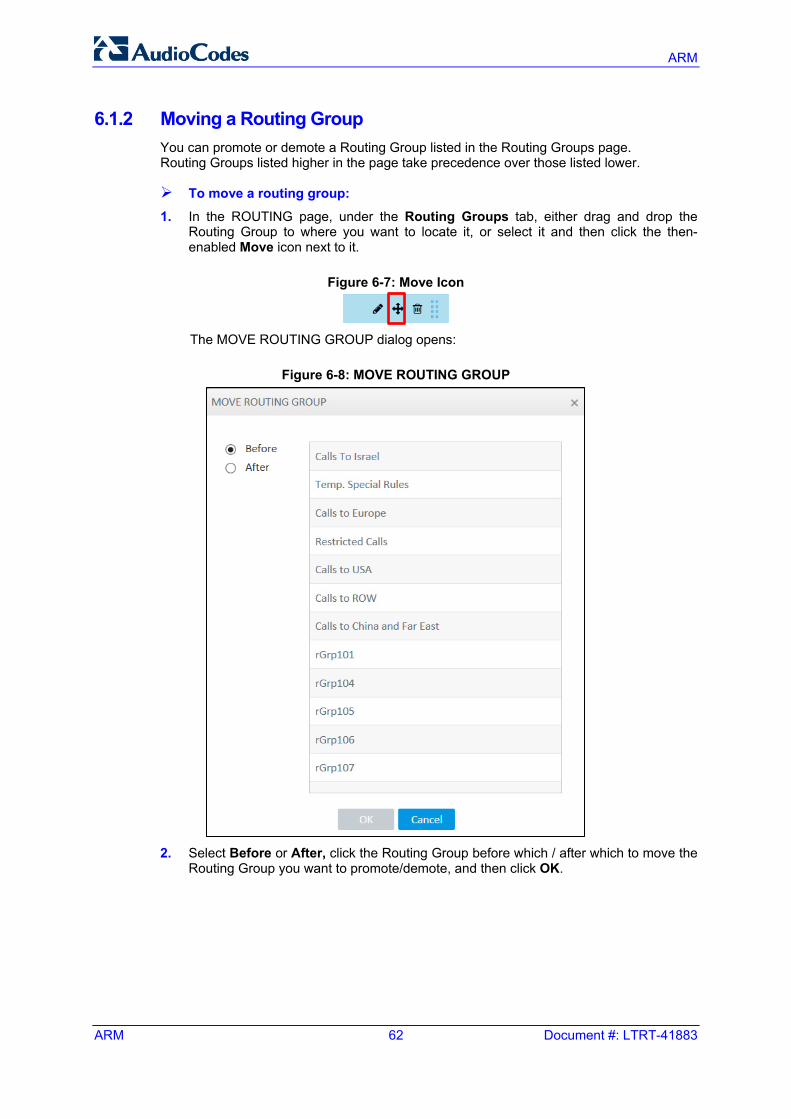
ARM
ARM 62 Document #: LTRT-41883
6.1.2 Moving a Routing Group You can promote or demote a Routing Group listed in the Routing Groups page. Routing Groups listed higher in the page take precedence over those listed lower.
To move a routing group:
1. In the ROUTING page, under the Routing Groups tab, either drag and drop the Routing Group to where you want to locate it, or select it and then click the then-enabled Move icon next to it.
Figure 6-7: Move Icon
The MOVE ROUTING GROUP dialog opens:
Figure 6-8: MOVE ROUTING GROUP
2. Select Before or After, click the Routing Group before which / after which to move the
Routing Group you want to promote/demote, and then click OK.
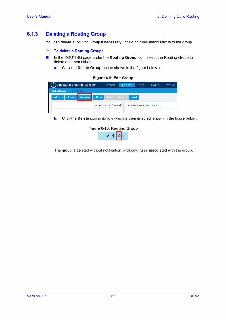
User's Manual 6. Defining Calls Routing
Version 7.2 63 ARM
6.1.3 Deleting a Routing Group You can delete a Routing Group if necessary, including rules associated with the group.
To delete a Routing Group:
In the ROUTING page under the Routing Group icon, select the Routing Group to delete and then either: a. Click the Delete Group button shown in the figure below -or-
Figure 6-9: Edit Group
b. Click the Delete icon in its row which is then enabled, shown in the figure below.
Figure 6-10: Routing Group
The group is deleted without notification, including rules associated with the group.
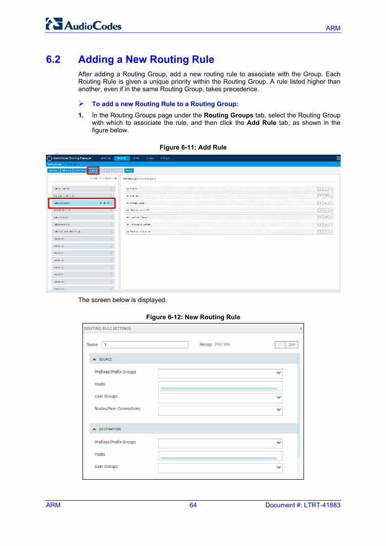
ARM
ARM 64 Document #: LTRT-41883
6.2 Adding a New Routing Rule After adding a Routing Group, add a new routing rule to associate with the Group. Each Routing Rule is given a unique priority within the Routing Group. A rule listed higher than another, even if in the same Routing Group, takes precedence.
To add a new Routing Rule to a Routing Group: 1. In the Routing Groups page under the Routing Groups tab, select the Routing Group
with which to associate the rule, and then click the Add Rule tab, as shown in the figure below.
Figure 6-11: Add Rule
The screen below is displayed.
Figure 6-12: New Routing Rule
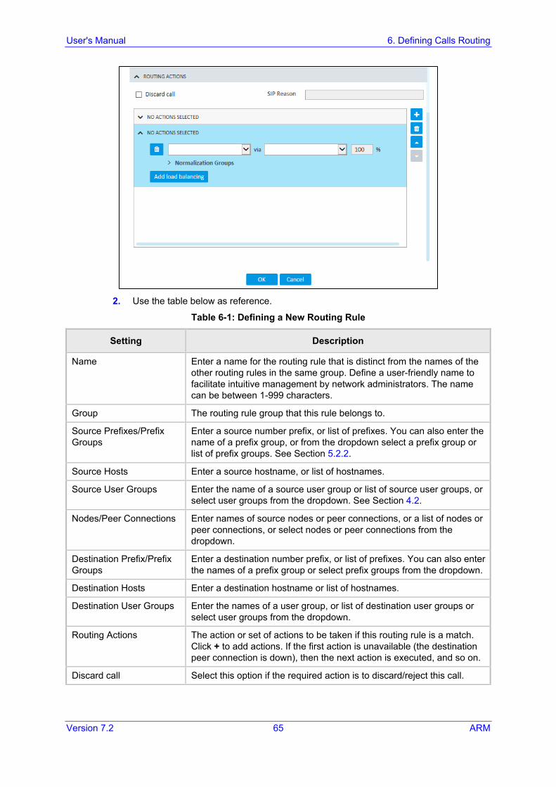
User's Manual 6. Defining Calls Routing
Version 7.2 65 ARM
2. Use the table below as reference.
Table 6-1: Defining a New Routing Rule
Setting Description
Name Enter a name for the routing rule that is distinct from the names of the other routing rules in the same group. Define a user-friendly name to facilitate intuitive management by network administrators. The name can be between 1-999 characters.
Group The routing rule group that this rule belongs to.
Source Prefixes/Prefix Groups
Enter a source number prefix, or list of prefixes. You can also enter the name of a prefix group, or from the dropdown select a prefix group or list of prefix groups. See Section 5.2.2.
Source Hosts Enter a source hostname, or list of hostnames.
Source User Groups Enter the name of a source user group or list of source user groups, or select user groups from the dropdown. See Section 4.2.
Nodes/Peer Connections Enter names of source nodes or peer connections, or a list of nodes or peer connections, or select nodes or peer connections from the dropdown.
Destination Prefix/Prefix Groups
Enter a destination number prefix, or list of prefixes. You can also enter the names of a prefix group or select prefix groups from the dropdown.
Destination Hosts Enter a destination hostname or list of hostnames.
Destination User Groups Enter the names of a user group, or list of destination user groups or select user groups from the dropdown.
Routing Actions The action or set of actions to be taken if this routing rule is a match. Click + to add actions. If the first action is unavailable (the destination peer connection is down), then the next action is executed, and so on.
Discard call Select this option if the required action is to discard/reject this call.
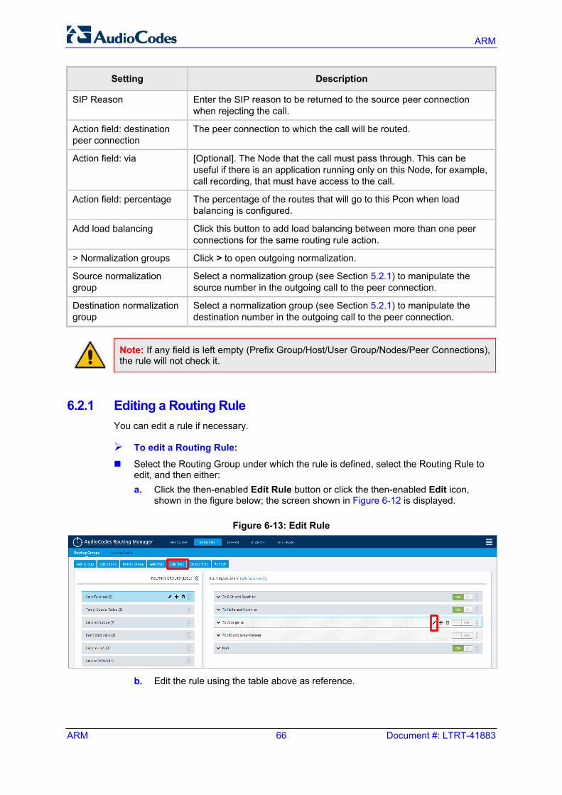
ARM
ARM 66 Document #: LTRT-41883
Setting Description
SIP Reason Enter the SIP reason to be returned to the source peer connection when rejecting the call.
Action field: destination peer connection
The peer connection to which the call will be routed.
Action field: via [Optional]. The Node that the call must pass through. This can be useful if there is an application running only on this Node, for example, call recording, that must have access to the call.
Action field: percentage The percentage of the routes that will go to this Pcon when load balancing is configured.
Add load balancing Click this button to add load balancing between more than one peer connections for the same routing rule action.
> Normalization groups Click > to open outgoing normalization.
Source normalization group
Select a normalization group (see Section 5.2.1) to manipulate the source number in the outgoing call to the peer connection.
Destination normalization group
Select a normalization group (see Section 5.2.1) to manipulate the destination number in the outgoing call to the peer connection.
Note: If any field is left empty (Prefix Group/Host/User Group/Nodes/Peer Connections), the rule will not check it.
6.2.1 Editing a Routing Rule You can edit a rule if necessary.
To edit a Routing Rule: Select the Routing Group under which the rule is defined, select the Routing Rule to
edit, and then either: a. Click the then-enabled Edit Rule button or click the then-enabled Edit icon,
shown in the figure below; the screen shown in Figure 6-12 is displayed.
Figure 6-13: Edit Rule
b. Edit the rule using the table above as reference.
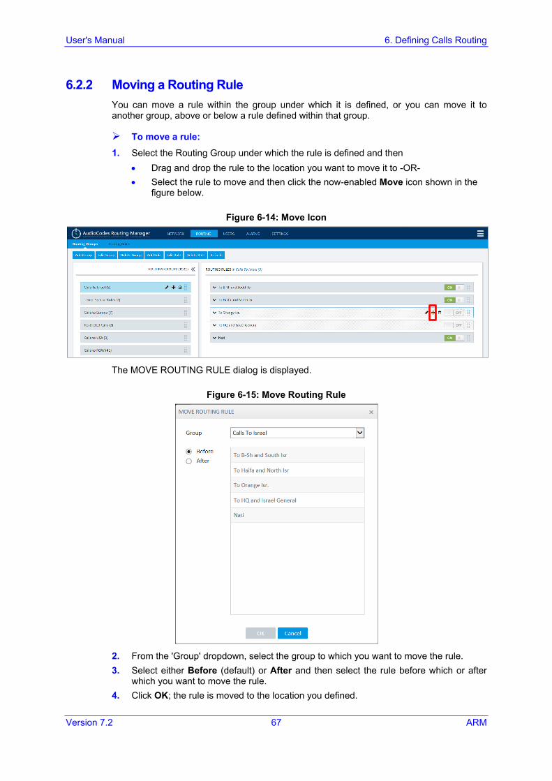
User's Manual 6. Defining Calls Routing
Version 7.2 67 ARM
6.2.2 Moving a Routing Rule You can move a rule within the group under which it is defined, or you can move it to another group, above or below a rule defined within that group.
To move a rule:
1. Select the Routing Group under which the rule is defined and then • Drag and drop the rule to the location you want to move it to -OR- • Select the rule to move and then click the now-enabled Move icon shown in the
figure below.
Figure 6-14: Move Icon
The MOVE ROUTING RULE dialog is displayed.
Figure 6-15: Move Routing Rule
2. From the 'Group' dropdown, select the group to which you want to move the rule. 3. Select either Before (default) or After and then select the rule before which or after
which you want to move the rule. 4. Click OK; the rule is moved to the location you defined.
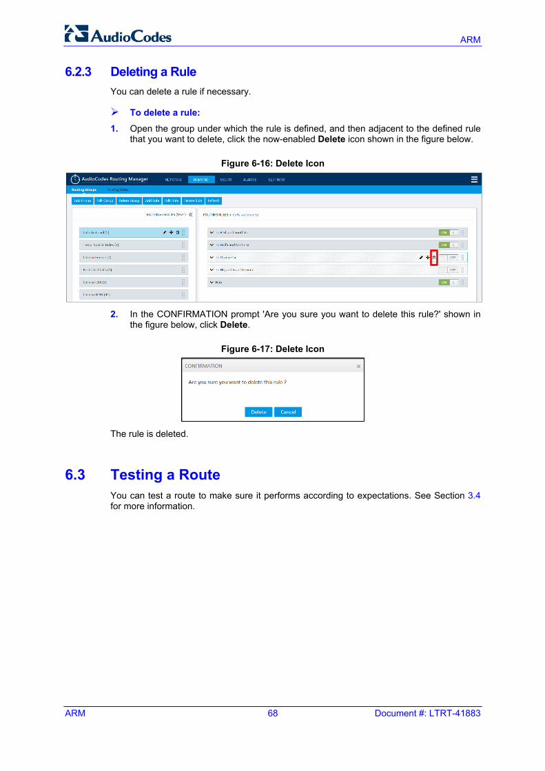
ARM
ARM 68 Document #: LTRT-41883
6.2.3 Deleting a Rule You can delete a rule if necessary.
To delete a rule:
1. Open the group under which the rule is defined, and then adjacent to the defined rule that you want to delete, click the now-enabled Delete icon shown in the figure below.
Figure 6-16: Delete Icon
2. In the CONFIRMATION prompt 'Are you sure you want to delete this rule?' shown in
the figure below, click Delete.
Figure 6-17: Delete Icon
The rule is deleted.
6.3 Testing a Route You can test a route to make sure it performs according to expectations. See Section 3.4 for more information.
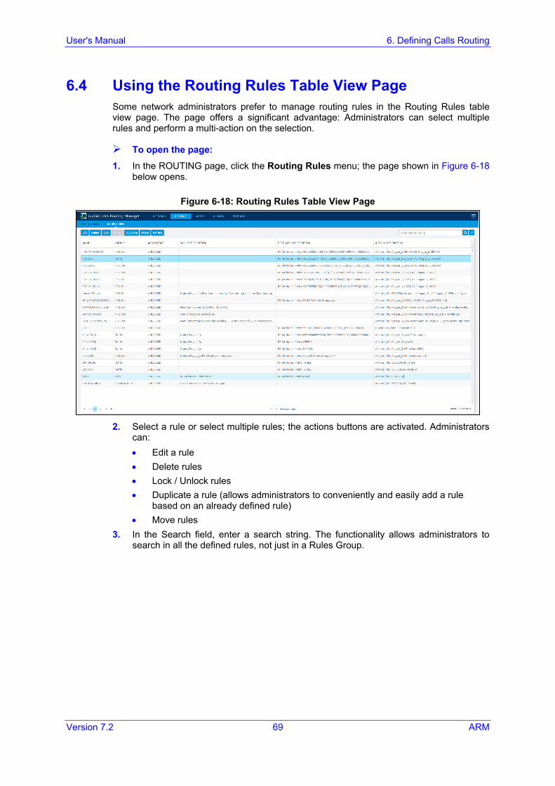
User's Manual 6. Defining Calls Routing
Version 7.2 69 ARM
6.4 Using the Routing Rules Table View Page Some network administrators prefer to manage routing rules in the Routing Rules table view page. The page offers a significant advantage: Administrators can select multiple rules and perform a multi-action on the selection.
To open the page: 1. In the ROUTING page, click the Routing Rules menu; the page shown in Figure 6-18
below opens.
Figure 6-18: Routing Rules Table View Page
2. Select a rule or select multiple rules; the actions buttons are activated. Administrators
can: • Edit a rule • Delete rules • Lock / Unlock rules • Duplicate a rule (allows administrators to conveniently and easily add a rule
based on an already defined rule) • Move rules
3. In the Search field, enter a search string. The functionality allows administrators to search in all the defined rules, not just in a Rules Group.

ARM
ARM 70 Document #: LTRT-41883
This page is intentionally left blank.
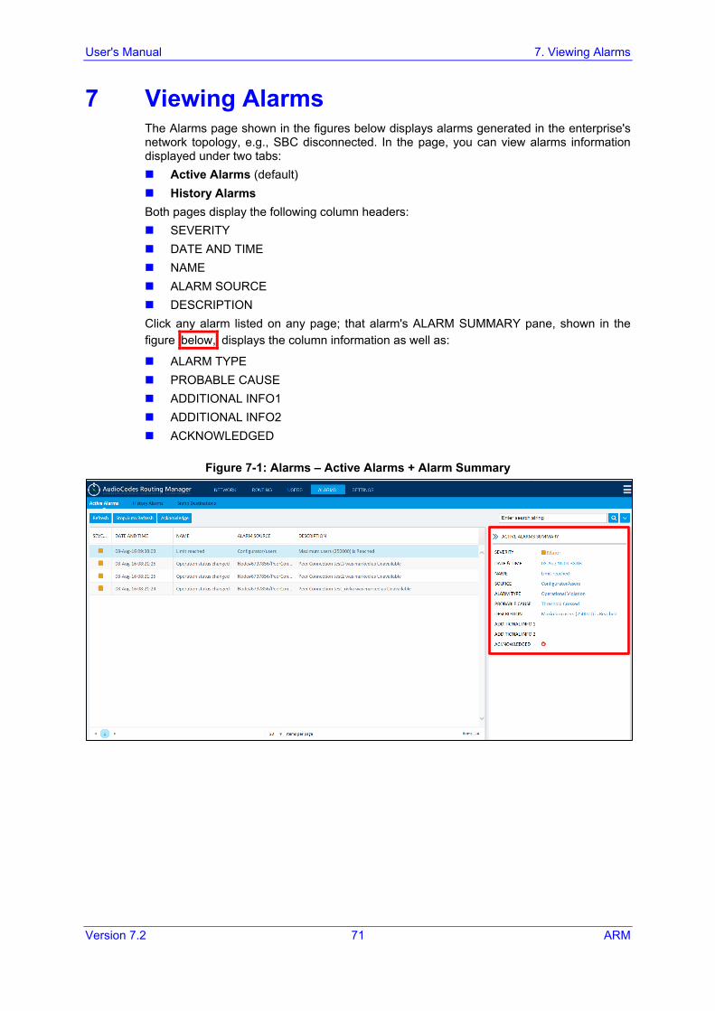
User's Manual 7. Viewing Alarms
Version 7.2 71 ARM
7 Viewing Alarms The Alarms page shown in the figures below displays alarms generated in the enterprise's network topology, e.g., SBC disconnected. In the page, you can view alarms information displayed under two tabs: Active Alarms (default) History Alarms Both pages display the following column headers: SEVERITY DATE AND TIME NAME ALARM SOURCE DESCRIPTION Click any alarm listed on any page; that alarm's ALARM SUMMARY pane, shown in the figure below, displays the column information as well as:
ALARM TYPE PROBABLE CAUSE ADDITIONAL INFO1 ADDITIONAL INFO2 ACKNOWLEDGED
Figure 7-1: Alarms – Active Alarms + Alarm Summary
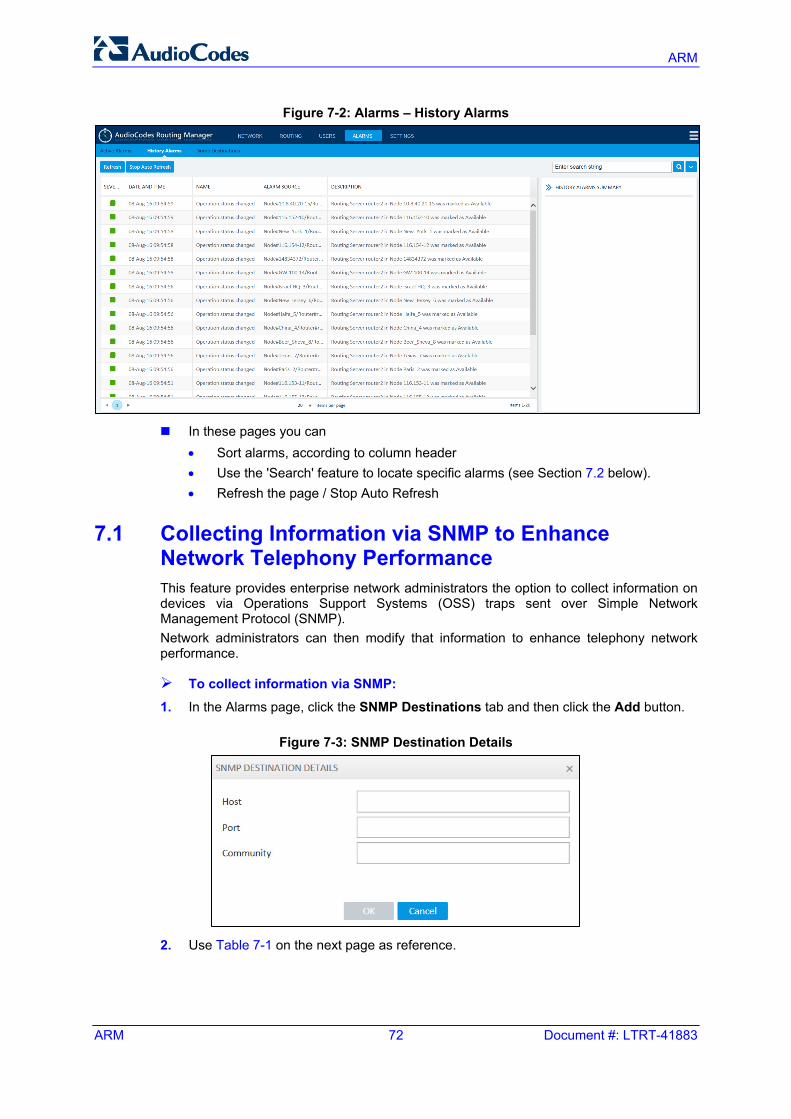
ARM
ARM 72 Document #: LTRT-41883
Figure 7-2: Alarms – History Alarms
In these pages you can
• Sort alarms, according to column header • Use the 'Search' feature to locate specific alarms (see Section 7.2 below). • Refresh the page / Stop Auto Refresh
7.1 Collecting Information via SNMP to Enhance Network Telephony Performance This feature provides enterprise network administrators the option to collect information on devices via Operations Support Systems (OSS) traps sent over Simple Network Management Protocol (SNMP). Network administrators can then modify that information to enhance telephony network performance.
To collect information via SNMP: 1. In the Alarms page, click the SNMP Destinations tab and then click the Add button.
Figure 7-3: SNMP Destination Details
2. Use Table 7-1 on the next page as reference.
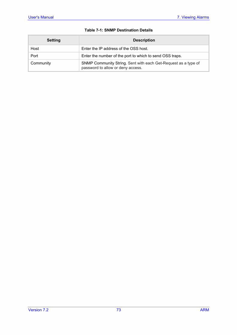
User's Manual 7. Viewing Alarms
Version 7.2 73 ARM
Table 7-1: SNMP Destination Details
Setting Description
Host Enter the IP address of the OSS host.
Port Enter the number of the port to which to send OSS traps.
Community SNMP Community String. Sent with each Get-Request as a type of password to allow or deny access.
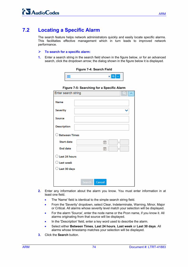
ARM
ARM 74 Document #: LTRT-41883
7.2 Locating a Specific Alarm The search feature helps network administrators quickly and easily locate specific alarms. This facilitaties effective management which in turn leads to improved network performance.
To search for a specific alarm: 1. Enter a search string in the search field shown in the figure below, or for an advanced
search, click the dropdown arrow; the dialog shown in the figure below it is displayed.
Figure 7-4: Search Field
Figure 7-5: Searching for a Specific Alarm
2. Enter any information about the alarm you know. You must enter information in at
least one field. • The 'Name' field is identical to the simple search string field. • From the 'Severity' dropdown, select Clear, Indeterminate, Warning, Minor, Major
or Critical. All alarms whose severity level match your selection will be displayed. • For the alarm 'Source', enter the node name or the Pcon name, if you know it. All
alarms originating from that source will be displayed. • In the 'Description' field, enter a key word used to describe the alarm. • Select either Between Times, Last 24 hours, Last week or Last 30 days. All
alarms whose timestamp matches your selection will be displayed. 3. Click the Search button.
User's Manual 8. Migrating Device Routing to the ARM
Version 7.2 75 ARM
8 Migrating Device Routing to the ARM This section shows how to migrate device routing to the ARM.
8.1 Getting Acquainted with Device Types Routing Logic Before migrating device routing to the ARM, it's best to first get acquainted with the routing logic of AudioCodes' device types. This section describes the routing logic of the three AudioCodes device types: SBC routing logic (see Section 8.1.1 below) Media Gateway routing logic (see Section 8.1.2 below) Hybrid Device routing logic (see Section 8.1.3 below)
8.1.1 SBC Routing Logic AudioCodes' SBC routes and handles IP-to-IP calls. In the Web interface, SBC routing logic is configured in the IP-to-IP Routing table. A row in the table can be an ARM rule. The SBC attempts to match rules configured in the table according to the following logic:
If, when parsing the table, the SBC reaches an ARM row, it attempts to get a route from the ARM. a. If the ARM has no routes on the first request, the SBC proceeds to the next
routing rule. b. If the ARM has at least one route, the SBC implements them according to the
ARM's logic. c. If all ARM routes fail, the SBC does not proceed to the next routing rule in its own
routing table.
8.1.2 Media Gateway Routing Logic AudioCodes' Media Gateway routes and handles IP-to-Tel and Tel-to-IP calls. It also handles Tel-to-Tel calls, automatically handled by the ARM using an internal loopback IP Group which is displayed in the ARM GUI.
Media Gateway routing logic is configured in the IP-to-Tel and Tel-to-IP table. No row in either table can be ARM. ARM is configured in the Web interface's Routing General Parameters page using the external parameter 'GW Routing Server' = Yes.
The Media Gateway first sends a request to the ARM as if it were the first row in both IP-to-Tel and Tel-to-IP tables. a. If the ARM has no routes upon the first request, the Media Gateway proceeds to
the next routing rules. b. If the ARM has at least one route, the Media Gateway implements the routes
according to the ARM's logic. c. If all ARM routes fail, the Media Gateway does not proceed to the next routing
rule in its own routing table.
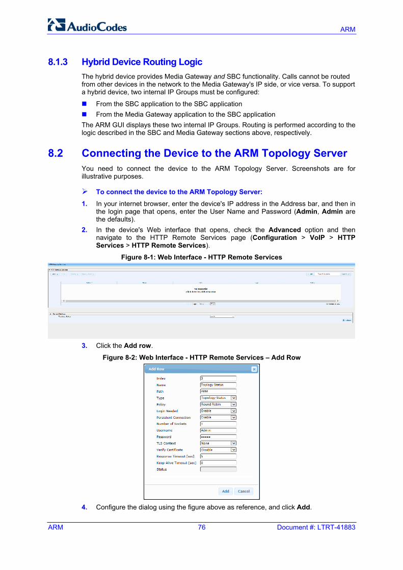
ARM
ARM 76 Document #: LTRT-41883
8.1.3 Hybrid Device Routing Logic The hybrid device provides Media Gateway and SBC functionality. Calls cannot be routed from other devices in the network to the Media Gateway's IP side, or vice versa. To support a hybrid device, two internal IP Groups must be configured:
From the SBC application to the SBC application From the Media Gateway application to the SBC application The ARM GUI displays these two internal IP Groups. Routing is performed according to the logic described in the SBC and Media Gateway sections above, respectively.
8.2 Connecting the Device to the ARM Topology Server You need to connect the device to the ARM Topology Server. Screenshots are for illustrative purposes.
To connect the device to the ARM Topology Server:
1. In your internet browser, enter the device's IP address in the Address bar, and then in the login page that opens, enter the User Name and Password (Admin, Admin are the defaults).
2. In the device's Web interface that opens, check the Advanced option and then navigate to the HTTP Remote Services page (Configuration > VoIP > HTTP Services > HTTP Remote Services).
Figure 8-1: Web Interface - HTTP Remote Services
3. Click the Add row.
Figure 8-2: Web Interface - HTTP Remote Services – Add Row
4. Configure the dialog using the figure above as reference, and click Add.
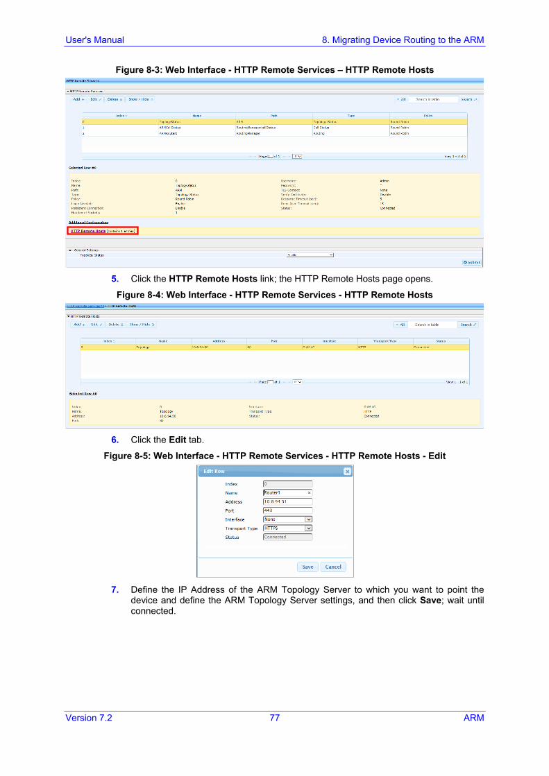
User's Manual 8. Migrating Device Routing to the ARM
Version 7.2 77 ARM
Figure 8-3: Web Interface - HTTP Remote Services – HTTP Remote Hosts
5. Click the HTTP Remote Hosts link; the HTTP Remote Hosts page opens.
Figure 8-4: Web Interface - HTTP Remote Services - HTTP Remote Hosts
6. Click the Edit tab.
Figure 8-5: Web Interface - HTTP Remote Services - HTTP Remote Hosts - Edit
7. Define the IP Address of the ARM Topology Server to which you want to point the
device and define the ARM Topology Server settings, and then click Save; wait until connected.
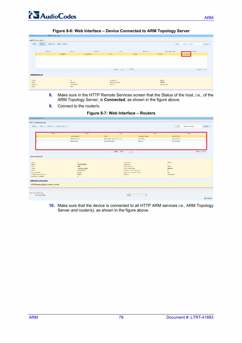
ARM
ARM 78 Document #: LTRT-41883
Figure 8-6: Web Interface – Device Connected to ARM Topology Server
8. Make sure in the HTTP Remote Services screen that the Status of the host, i.e., of the
ARM Topology Server, is Connected, as shown in the figure above. 9. Connect to the router/s.
Figure 8-7: Web Interface – Routers
10. Make sure that the device is connected to all HTTP ARM services i.e., ARM Topology
Server and router/s), as shown in the figure above.
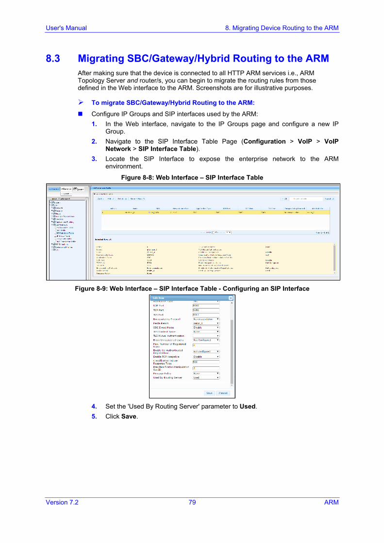
User's Manual 8. Migrating Device Routing to the ARM
Version 7.2 79 ARM
8.3 Migrating SBC/Gateway/Hybrid Routing to the ARM After making sure that the device is connected to all HTTP ARM services i.e., ARM Topology Server and router/s, you can begin to migrate the routing rules from those defined in the Web interface to the ARM. Screenshots are for illustrative purposes.
To migrate SBC/Gateway/Hybrid Routing to the ARM:
Configure IP Groups and SIP interfaces used by the ARM: 1. In the Web interface, navigate to the IP Groups page and configure a new IP
Group. 2. Navigate to the SIP Interface Table Page (Configuration > VoIP > VoIP
Network > SIP Interface Table). 3. Locate the SIP Interface to expose the enterprise network to the ARM
environment.
Figure 8-8: Web Interface – SIP Interface Table
Figure 8-9: Web Interface – SIP Interface Table - Configuring an SIP Interface
4. Set the 'Used By Routing Server' parameter to Used. 5. Click Save.
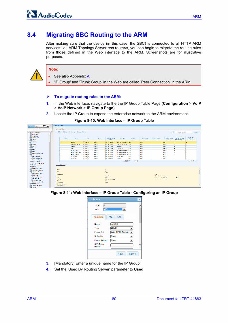
ARM
ARM 80 Document #: LTRT-41883
8.4 Migrating SBC Routing to the ARM After making sure that the device (in this case, the SBC) is connected to all HTTP ARM services i.e., ARM Topology Server and router/s, you can begin to migrate the routing rules from those defined in the Web interface to the ARM. Screenshots are for illustrative purposes.
Note:
• See also Appendix A. • 'IP Group' and 'Trunk Group' in the Web are called 'Peer Connection' in the ARM.
To migrate routing rules to the ARM:
1. In the Web interface, navigate to the the IP Group Table Page (Configuration > VoIP > VoIP Network > IP Group Page).
2. Locate the IP Group to expose the enterprise network to the ARM environment.
Figure 8-10: Web Interface – IP Group Table
Figure 8-11: Web Interface – IP Group Table - Configuring an IP Group
3. [Mandatory] Enter a unique name for the IP Group. 4. Set the 'Used By Routing Server' parameter to Used.
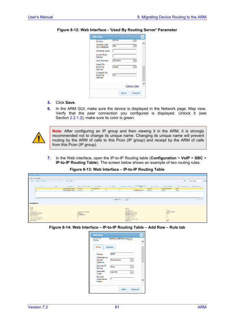
User's Manual 8. Migrating Device Routing to the ARM
Version 7.2 81 ARM
Figure 8-12: Web Interface - 'Used By Routing Server' Parameter
5. Click Save. 6. In the ARM GUI, make sure the device is displayed in the Network page, Map view.
Verify that the peer connection you configured is displayed. Unlock it (see Section 2.2.1.2); make sure its color is green.
Note: After configuring an IP group and then viewing it in the ARM, it is strongly recommended not to change its unique name. Changing its unique name will prevent routing by the ARM of calls to this Pcon (IP group) and receipt by the ARM of calls from this Pcon (IP group).
7. In the Web interface, open the IP-to-IP Routing table (Configuration > VoIP > SBC >
IP-to-IP Routing Table). The screen below shows an example of two routing rules.
Figure 8-13: Web Interface – IP-to-IP Routing Table
Figure 8-14: Web Interface – IP-to-IP Routing Table – Add Row – Rule tab
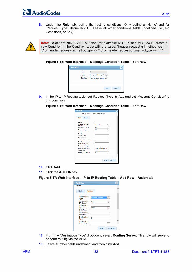
ARM
ARM 82 Document #: LTRT-41883
8. Under the Rule tab, define the routing conditions: Only define a 'Name' and for 'Request Type', define INVITE. Leave all other conditions fields undefined (i.e., No Conditions, or Any).
Note: To get not only INVITE but also (for example) NOTIFY and MESSAGE, create a new Condition in the Condition table with the value: "header.request-uri.methodtype == '5' or header.request-uri.methodtype == '13' or header.request-uri.methodtype == '14'"
Figure 8-15: Web Interface – Message Condition Table – Edit Row
9. In the IP-to-IP Routing table, set 'Request Type' to ALL and set 'Message Condition' to
this condition:
Figure 8-16: Web Interface – Message Condition Table – Edit Row
10. Click Add. 11. Click the ACTION tab.
Figure 8-17: Web Interface – IP-to-IP Routing Table – Add Row – Action tab
12. From the 'Destination Type' dropdown, select Routing Server. This rule will serve to
perform routing via the ARM. 13. Leave all other fields undefined, and then click Add.
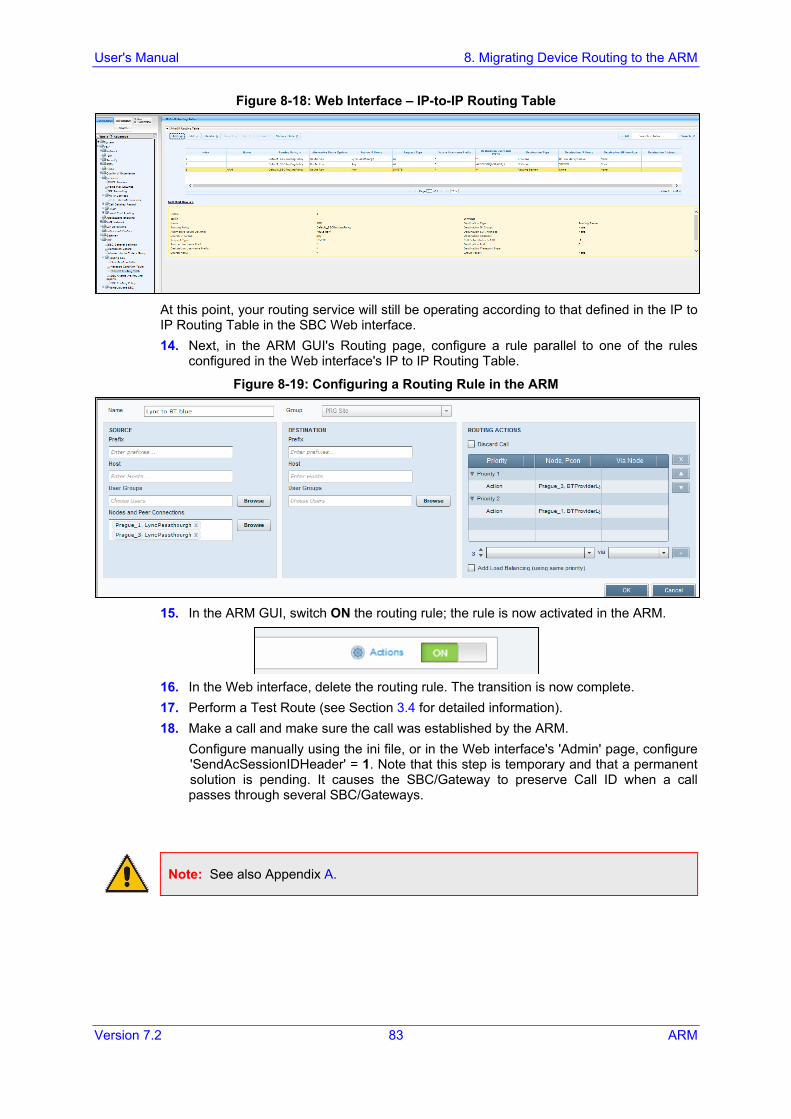
User's Manual 8. Migrating Device Routing to the ARM
Version 7.2 83 ARM
Figure 8-18: Web Interface – IP-to-IP Routing Table
At this point, your routing service will still be operating according to that defined in the IP to IP Routing Table in the SBC Web interface. 14. Next, in the ARM GUI's Routing page, configure a rule parallel to one of the rules
configured in the Web interface's IP to IP Routing Table.
Figure 8-19: Configuring a Routing Rule in the ARM
15. In the ARM GUI, switch ON the routing rule; the rule is now activated in the ARM.
16. In the Web interface, delete the routing rule. The transition is now complete. 17. Perform a Test Route (see Section 3.4 for detailed information). 18. Make a call and make sure the call was established by the ARM.
Configure manually using the ini file, or in the Web interface's 'Admin' page, configure 'SendAcSessionIDHeader' = 1. Note that this step is temporary and that a permanent solution is pending. It causes the SBC/Gateway to preserve Call ID when a call passes through several SBC/Gateways.
Note: See also Appendix A.
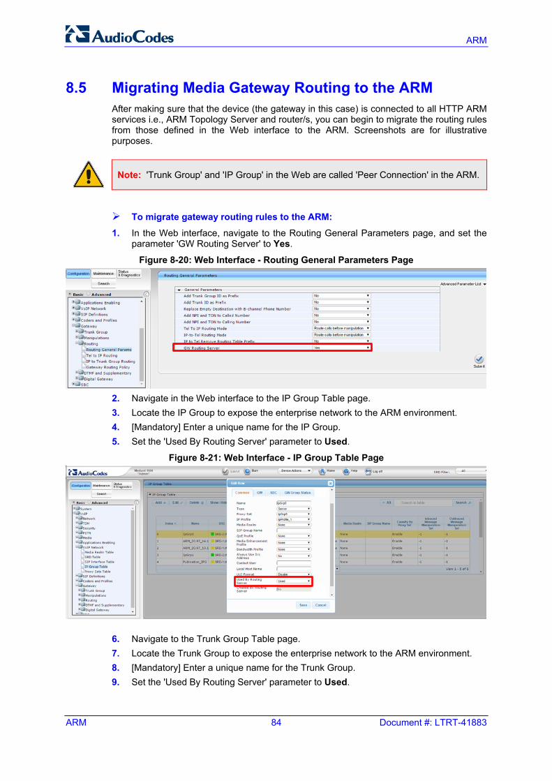
ARM
ARM 84 Document #: LTRT-41883
8.5 Migrating Media Gateway Routing to the ARM After making sure that the device (the gateway in this case) is connected to all HTTP ARM services i.e., ARM Topology Server and router/s, you can begin to migrate the routing rules from those defined in the Web interface to the ARM. Screenshots are for illustrative purposes.
Note: 'Trunk Group' and 'IP Group' in the Web are called 'Peer Connection' in the ARM.
To migrate gateway routing rules to the ARM: 1. In the Web interface, navigate to the Routing General Parameters page, and set the
parameter 'GW Routing Server' to Yes. Figure 8-20: Web Interface - Routing General Parameters Page
2. Navigate in the Web interface to the IP Group Table page. 3. Locate the IP Group to expose the enterprise network to the ARM environment. 4. [Mandatory] Enter a unique name for the IP Group. 5. Set the 'Used By Routing Server' parameter to Used.
Figure 8-21: Web Interface - IP Group Table Page
6. Navigate to the Trunk Group Table page. 7. Locate the Trunk Group to expose the enterprise network to the ARM environment. 8. [Mandatory] Enter a unique name for the Trunk Group. 9. Set the 'Used By Routing Server' parameter to Used.
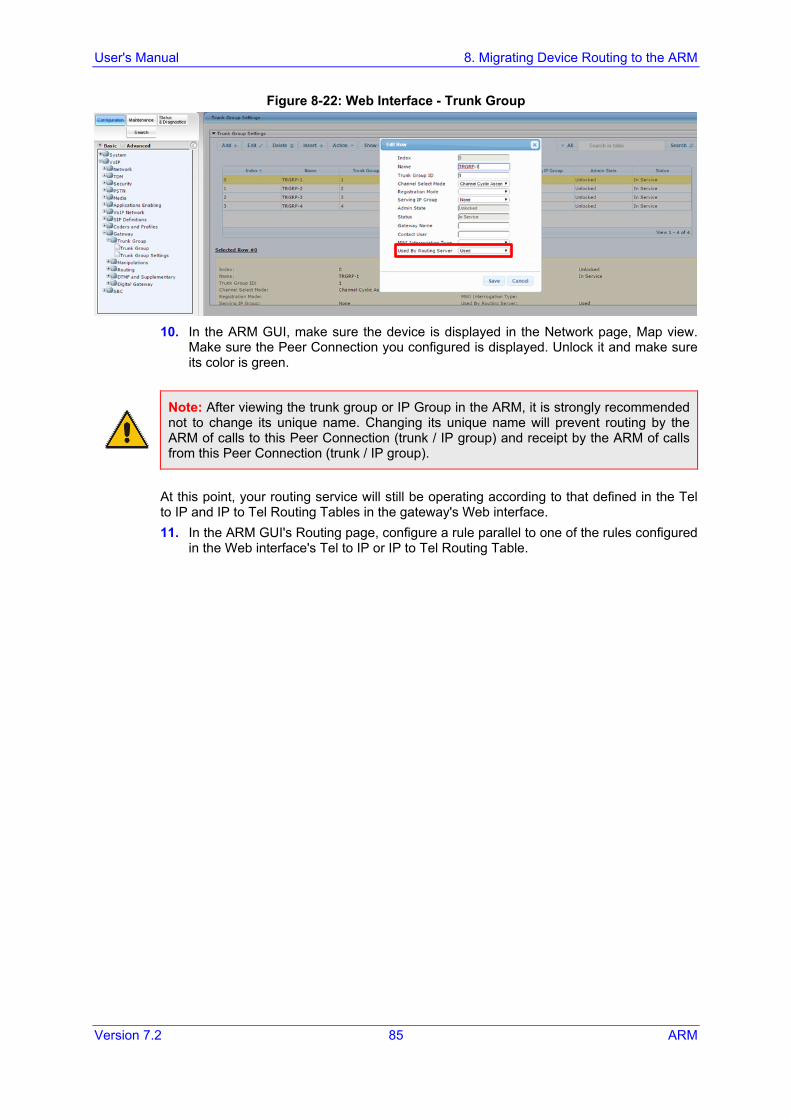
User's Manual 8. Migrating Device Routing to the ARM
Version 7.2 85 ARM
Figure 8-22: Web Interface - Trunk Group
10. In the ARM GUI, make sure the device is displayed in the Network page, Map view.
Make sure the Peer Connection you configured is displayed. Unlock it and make sure its color is green.
Note: After viewing the trunk group or IP Group in the ARM, it is strongly recommended not to change its unique name. Changing its unique name will prevent routing by the ARM of calls to this Peer Connection (trunk / IP group) and receipt by the ARM of calls from this Peer Connection (trunk / IP group).
At this point, your routing service will still be operating according to that defined in the Tel to IP and IP to Tel Routing Tables in the gateway's Web interface. 11. In the ARM GUI's Routing page, configure a rule parallel to one of the rules configured
in the Web interface's Tel to IP or IP to Tel Routing Table.
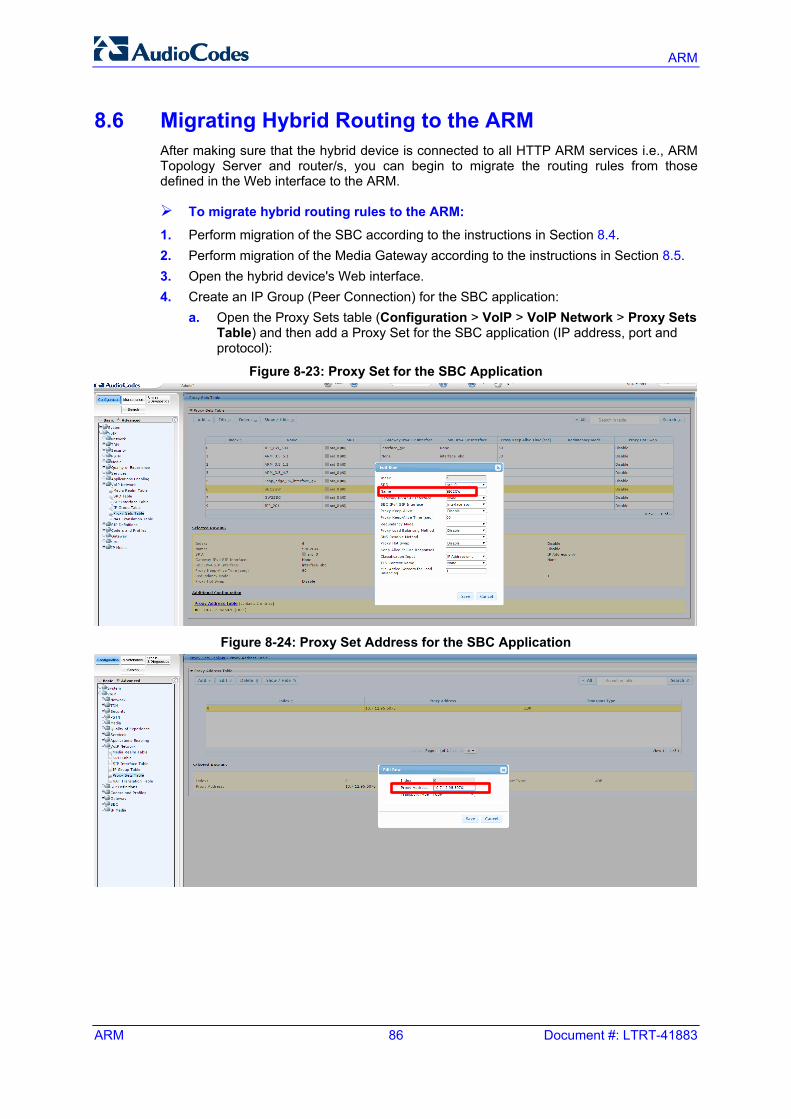
ARM
ARM 86 Document #: LTRT-41883
8.6 Migrating Hybrid Routing to the ARM After making sure that the hybrid device is connected to all HTTP ARM services i.e., ARM Topology Server and router/s, you can begin to migrate the routing rules from those defined in the Web interface to the ARM.
To migrate hybrid routing rules to the ARM:
1. Perform migration of the SBC according to the instructions in Section 8.4. 2. Perform migration of the Media Gateway according to the instructions in Section 8.5. 3. Open the hybrid device's Web interface. 4. Create an IP Group (Peer Connection) for the SBC application:
a. Open the Proxy Sets table (Configuration > VoIP > VoIP Network > Proxy Sets Table) and then add a Proxy Set for the SBC application (IP address, port and protocol):
Figure 8-23: Proxy Set for the SBC Application
Figure 8-24: Proxy Set Address for the SBC Application
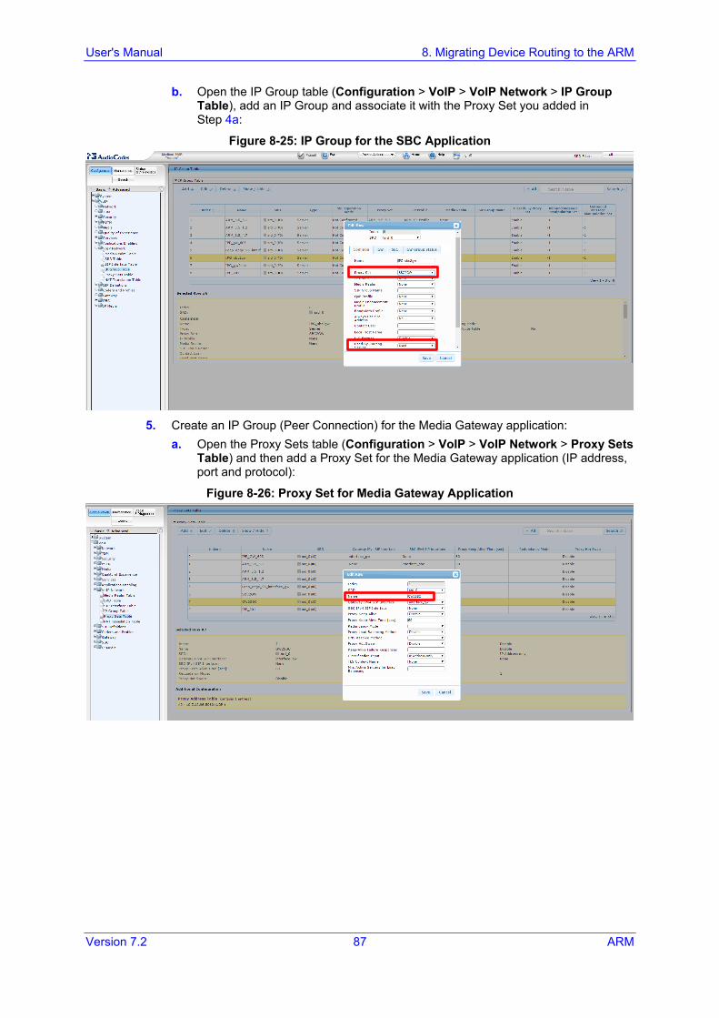
User's Manual 8. Migrating Device Routing to the ARM
Version 7.2 87 ARM
b. Open the IP Group table (Configuration > VoIP > VoIP Network > IP Group Table), add an IP Group and associate it with the Proxy Set you added in Step 4 a:
Figure 8-25: IP Group for the SBC Application
5. Create an IP Group (Peer Connection) for the Media Gateway application:
a. Open the Proxy Sets table (Configuration > VoIP > VoIP Network > Proxy Sets Table) and then add a Proxy Set for the Media Gateway application (IP address, port and protocol):
Figure 8-26: Proxy Set for Media Gateway Application
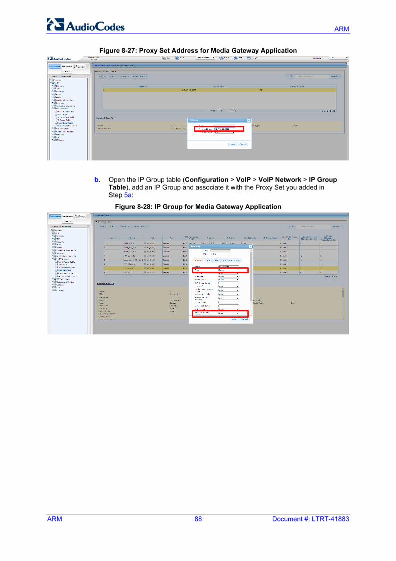
ARM
ARM 88 Document #: LTRT-41883
Figure 8-27: Proxy Set Address for Media Gateway Application
b. Open the IP Group table (Configuration > VoIP > VoIP Network > IP Group
Table), add an IP Group and associate it with the Proxy Set you added in Step 5 a:
Figure 8-28: IP Group for Media Gateway Application
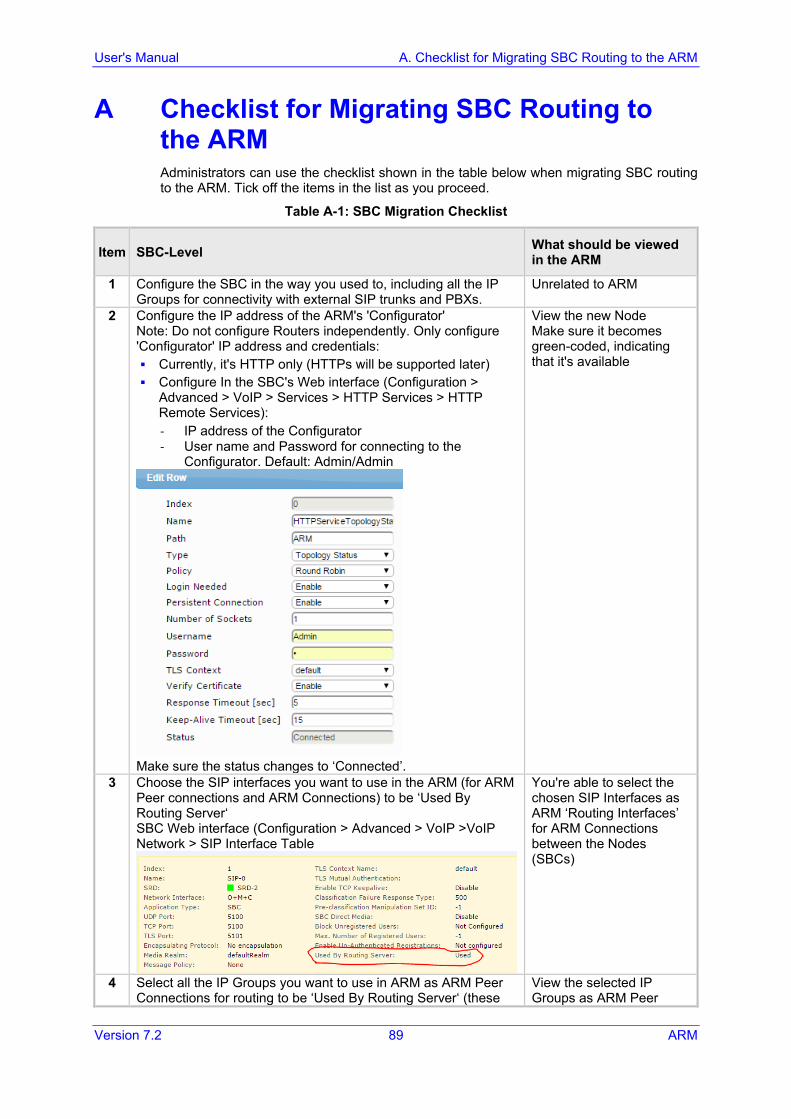
User's Manual A. Checklist for Migrating SBC Routing to the ARM
Version 7.2 89 ARM
A Checklist for Migrating SBC Routing to the ARM Administrators can use the checklist shown in the table below when migrating SBC routing to the ARM. Tick off the items in the list as you proceed.
Table A-1: SBC Migration Checklist
Item SBC-Level What should be viewed in the ARM
1 Configure the SBC in the way you used to, including all the IP Groups for connectivity with external SIP trunks and PBXs.
Unrelated to ARM
2 Configure the IP address of the ARM's 'Configurator' Note: Do not configure Routers independently. Only configure 'Configurator' IP address and credentials: Currently, it's HTTP only (HTTPs will be supported later) Configure In the SBC's Web interface (Configuration >
Advanced > VoIP > Services > HTTP Services > HTTP Remote Services): - IP address of the Configurator - User name and Password for connecting to the
Configurator. Default: Admin/Admin
Make sure the status changes to ‘Connected’.
View the new Node Make sure it becomes green-coded, indicating that it's available
3 Choose the SIP interfaces you want to use in the ARM (for ARM Peer connections and ARM Connections) to be ‘Used By Routing Server‘ SBC Web interface (Configuration > Advanced > VoIP >VoIP Network > SIP Interface Table
You're able to select the chosen SIP Interfaces as ARM ‘Routing Interfaces’ for ARM Connections between the Nodes (SBCs)
4 Select all the IP Groups you want to use in ARM as ARM Peer Connections for routing to be ‘Used By Routing Server‘ (these
View the selected IP Groups as ARM Peer
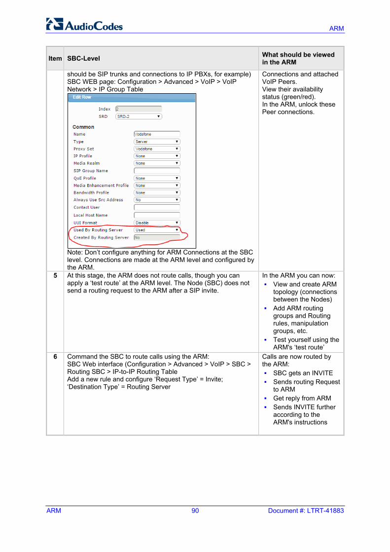
ARM
ARM 90 Document #: LTRT-41883
Item SBC-Level What should be viewed in the ARM
should be SIP trunks and connections to IP PBXs, for example) SBC WEB page: Configuration > Advanced > VoIP > VoIP Network > IP Group Table
Note: Don’t configure anything for ARM Connections at the SBC level. Connections are made at the ARM level and configured by the ARM.
Connections and attached VoIP Peers. View their availability status (green/red). In the ARM, unlock these Peer connections.
5 At this stage, the ARM does not route calls, though you can apply a ‘test route’ at the ARM level. The Node (SBC) does not send a routing request to the ARM after a SIP invite.
In the ARM you can now: View and create ARM
topology (connections between the Nodes)
Add ARM routing groups and Routing rules, manipulation groups, etc.
Test yourself using the ARM's ‘test route’
6 Command the SBC to route calls using the ARM: SBC Web interface (Configuration > Advanced > VoIP > SBC > Routing SBC > IP-to-IP Routing Table Add a new rule and configure ‘Request Type’ = Invite; ‘Destination Type’ = Routing Server
Calls are now routed by the ARM: SBC gets an INVITE Sends routing Request
to ARM Get reply from ARM Sends INVITE further
according to the ARM's instructions
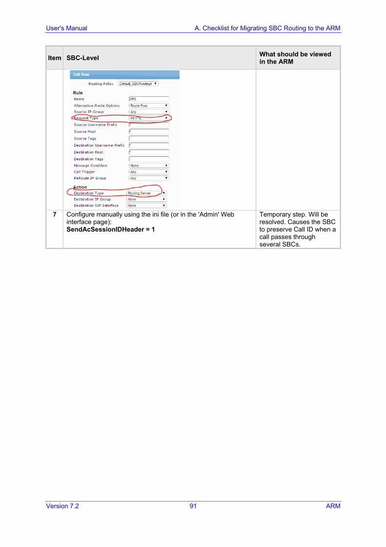
User's Manual A. Checklist for Migrating SBC Routing to the ARM
Version 7.2 91 ARM
Item SBC-Level What should be viewed in the ARM
7 Configure manually using the ini file (or in the 'Admin' Web
interface page): SendAcSessionIDHeader = 1
Temporary step. Will be resolved. Causes the SBC to preserve Call ID when a call passes through several SBCs.

ARM
ARM 92 Document #: LTRT-41883
This page is intentionally left blank.
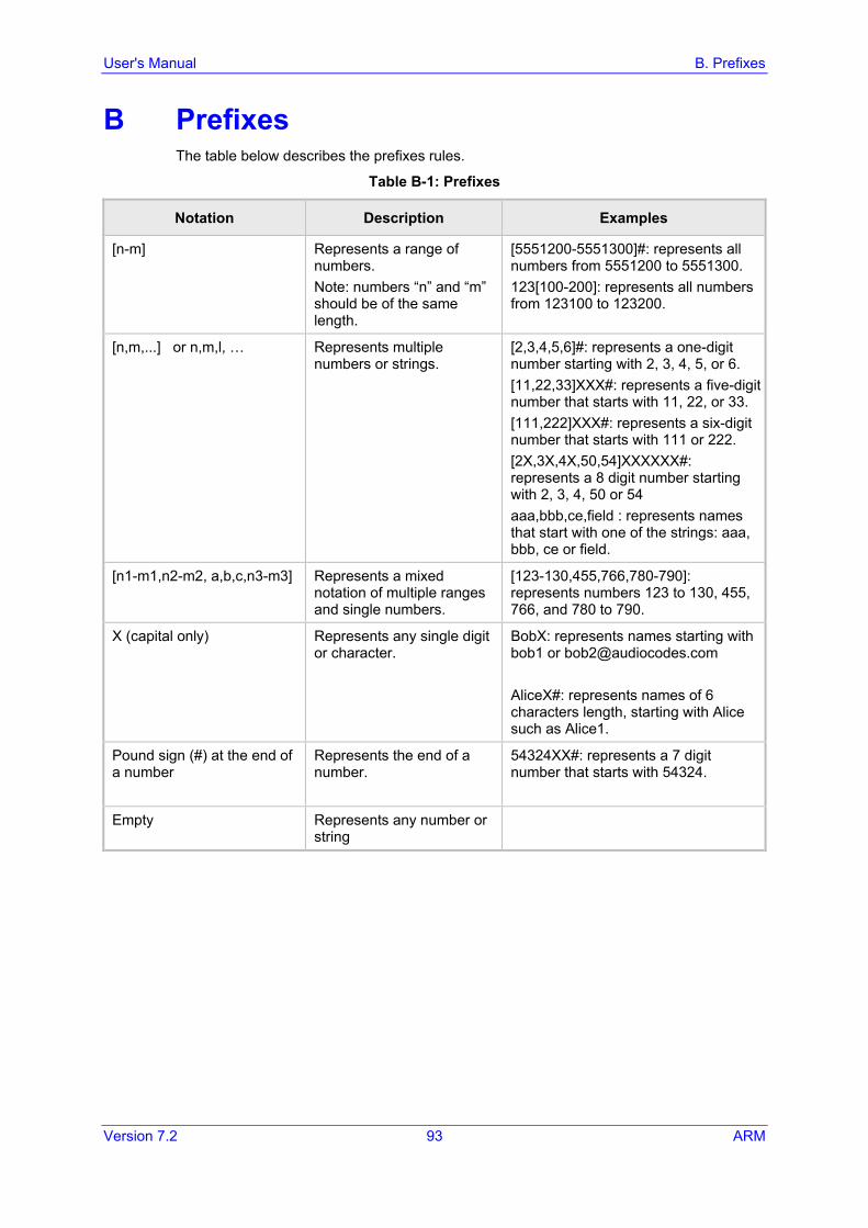
User's Manual B. Prefixes
Version 7.2 93 ARM
B Prefixes The table below describes the prefixes rules.
Table B-1: Prefixes
Notation Description Examples
[n-m] Represents a range of numbers. Note: numbers “n” and “m” should be of the same length.
[5551200-5551300]#: represents all numbers from 5551200 to 5551300. 123[100-200]: represents all numbers from 123100 to 123200.
[n,m,...] or n,m,l, … Represents multiple numbers or strings.
[2,3,4,5,6]#: represents a one-digit number starting with 2, 3, 4, 5, or 6. [11,22,33]XXX#: represents a five-digit number that starts with 11, 22, or 33. [111,222]XXX#: represents a six-digit number that starts with 111 or 222. [2X,3X,4X,50,54]XXXXXX#: represents a 8 digit number starting with 2, 3, 4, 50 or 54 aaa,bbb,ce,field : represents names that start with one of the strings: aaa, bbb, ce or field.
[n1-m1,n2-m2, a,b,c,n3-m3] Represents a mixed notation of multiple ranges and single numbers.
[123-130,455,766,780-790]: represents numbers 123 to 130, 455, 766, and 780 to 790.
X (capital only) Represents any single digit or character.
BobX: represents names starting with bob1 or [email protected] AliceX#: represents names of 6 characters length, starting with Alice such as Alice1.
Pound sign (#) at the end of a number
Represents the end of a number.
54324XX#: represents a 7 digit number that starts with 54324.
Empty Represents any number or string

ARM
ARM 94 Document #: LTRT-41883
This page is intentionally left blank.
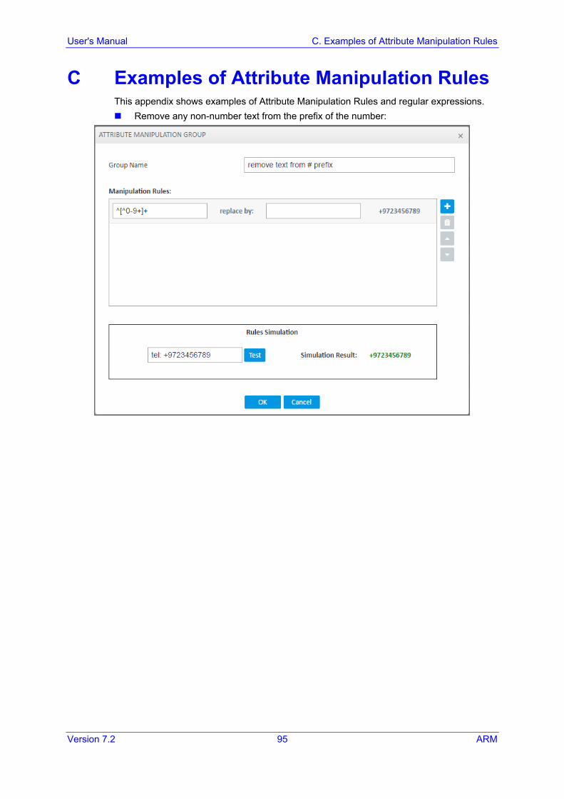
User's Manual C. Examples of Attribute Manipulation Rules
Version 7.2 95 ARM
C Examples of Attribute Manipulation Rules This appendix shows examples of Attribute Manipulation Rules and regular expressions. Remove any non-number text from the prefix of the number:
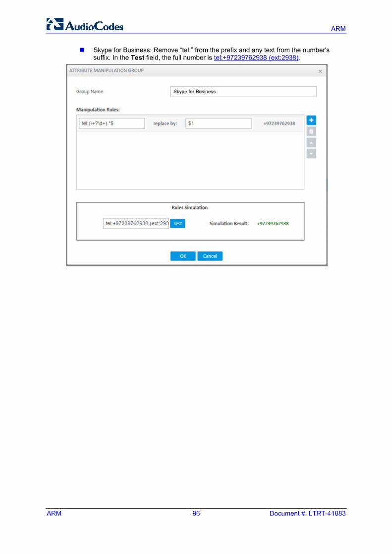
ARM
ARM 96 Document #: LTRT-41883
Skype for Business: Remove “tel:” from the prefix and any text from the number's suffix. In the Test field, the full number is tel:+97239762938 (ext:2938).
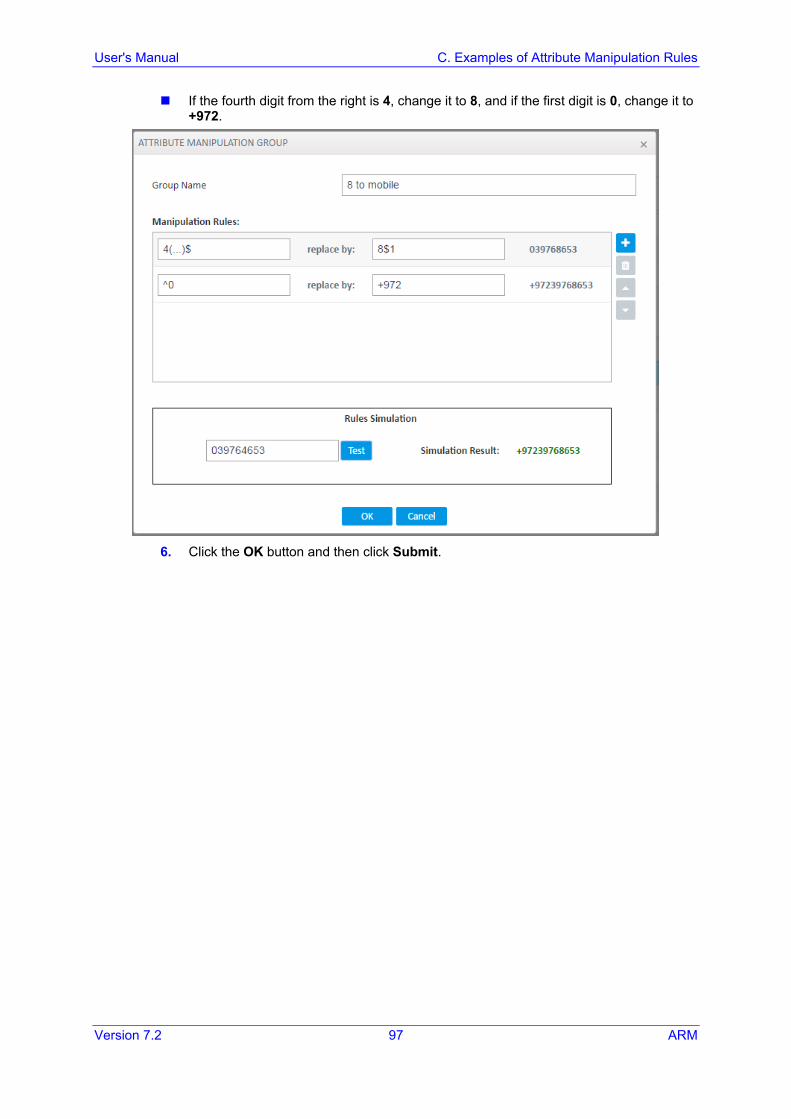
User's Manual C. Examples of Attribute Manipulation Rules
Version 7.2 97 ARM
If the fourth digit from the right is 4, change it to 8, and if the first digit is 0, change it to +972.
6. Click the OK button and then click Submit.

ARM
ARM 98 Document #: LTRT-41883
This page is intentionally left blank.
User's Manual D. Routing Path
Version 7.2 99 ARM
D Routing Path This appendix describes the routing path. A successful routing response contains 1 primary route and 0-5 alternate routes. The maximum number of routes to a specific ROUTING ACTION entry (Node or
Node/Pcon) is two. The routing path, from source to destination, is selected as follows:
• All possible paths, from source node to destination node/node+pcon in which all nodes and connections are active and unlocked, are selected.
• If via is selected, all entries that do not contain the via node are discarded. • All routing alternatives are sorted by weighted path, cost and then by number of
hops.

ARM
ARM 100 Document #: LTRT-41883
This page is intentionally left blank.
User's Manual E. Call Routing
Version 7.2 101 ARM
E Call Routing This appendix describes call routing. A routing request results in an HTTP error response if no available routing is available. A routing request from a source node which has an alternate route option returns the
next alternate route option. The call route is not recalculated. If the alternate route list is empty, a 404 result is returned.
A routing request from a node which is not the source node returns the next hop in the routing chain according to the original route selection. The routing logic is not performed again.

International Headquarters AudioCodes Inc. 1 Hayarden Street, 27 World’s Fair Drive, Airport City Somerset, NJ 08873 Lod 7019900, Israel Tel: +1-732-469-0880 Tel: +972-3-976-4000 Fax: +1-732-469-2298 Fax: +972-3-976-4040 Contact us: www.audiocodes.com/info Website: www.audiocodes.com
Document #: LTRT-41883