audio transformer design manual - robert g. wolpert (2004)
TRANSCRIPT

8/17/2019 Audio Transformer Design Manual - Robert G. Wolpert (2004)
http://slidepdf.com/reader/full/audio-transformer-design-manual-robert-g-wolpert-2004 1/117
AUDIO TR�NSF0 $ E
EIGN M NU L
ROBERT G. WOLPERT
8/17/2019 Audio Transformer Design Manual - Robert G. Wolpert (2004)
http://slidepdf.com/reader/full/audio-transformer-design-manual-robert-g-wolpert-2004 2/117
AUDIO TR�SFOR E
DEI6N MANUAL
ROBERT G. WOLPERT
8/17/2019 Audio Transformer Design Manual - Robert G. Wolpert (2004)
http://slidepdf.com/reader/full/audio-transformer-design-manual-robert-g-wolpert-2004 3/117
PREFACE
This manual is intended to show how to design and manufacture aud otransformers.
It will explain the various things that have to be considered and theproblems that wi l l be encountered in achieving the desi red results. It wi llshow how to design to meet the requirements and give examples and testresults.
It will a so give methods of manufacturing to achieve the results desired,with some of the things that will prevent the design from beingsuccessfu I.
Th is manual is written with the assum ption that the designer hasexperience in the design of power transformers herefore, it covers onlythose manufactur ng techniques that are different and necessary toachieve the proper results in an audio transformer.
If the designer needs more information on the construction methods, theTRANSFORMER DESIGN AND MANUFACTURING MANUAL published by theauthor in 1984, or some other publication, should be cons lted.
The appendix will have various tables and charts to assist in the design ofthe transformers.
Robert G. Wolpert
page 1
8/17/2019 Audio Transformer Design Manual - Robert G. Wolpert (2004)
http://slidepdf.com/reader/full/audio-transformer-design-manual-robert-g-wolpert-2004 4/117
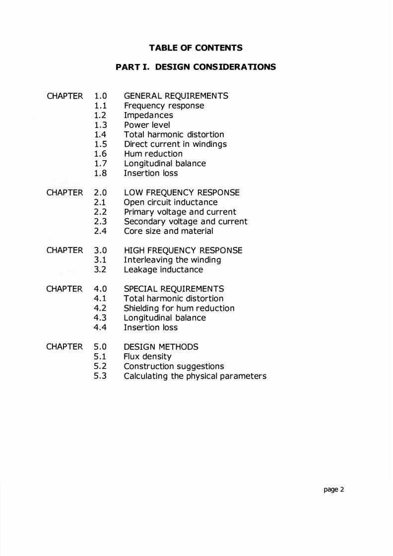
TABLE OF CONTENTS
PART I. DESIGN CONS IDERATIONS
C APTER 1 . 0 GENERAL REQUIREMENTS1 . 1 Frequency response1.2 Impedances1 . 3 Power level1.4 Total harmonic distortion1 5 Direct current in windings1 6 um reduction1 . 7 Longitudinal balance1 . 8 Insertion loss
CHAPTER 2 . 0 LOW FREQUENCY RESPONSE2.1 Open circuit inductance2.2 Primary voltage and current2 .3 Secondary voltage and current2.4 Core size and material
C APTER 3 . 0 IG FREQUENCY RESPONSE3 . 1 nterleaving the winding3.2 Leakage inductance
C AP ER 4 0 SPECIAL REQUIREMENTS4. 1 otal harmonic disto tion4.2 Shielding for hum reduction4 .3 Longitudinal balance4.4 Insert on loss
C APTER 5 . 0 DESIGN MET ODS5 . 1 Flux density5 .2 Construction suggestions5 . 3 Calculating the physical parameters
page 2

8/17/2019 Audio Transformer Design Manual - Robert G. Wolpert (2004)
http://slidepdf.com/reader/full/audio-transformer-design-manual-robert-g-wolpert-2004 5/117
PART II. DESIGN EXAM PLES
Example 1 Voice frequency telephone transformer
Example 2 : Audio output transfo mer
Example 3: Line to voice coil transformer
Symbo s usedDB-Watts tableWire tableLamination tableTotal harmonic distortion table
APPENDIX
Wire size turns - lamination tables
pa ge 3
8/17/2019 Audio Transformer Design Manual - Robert G. Wolpert (2004)
http://slidepdf.com/reader/full/audio-transformer-design-manual-robert-g-wolpert-2004 6/117
PART I. DESIGN CONSIDERATIONS
page 4

8/17/2019 Audio Transformer Design Manual - Robert G. Wolpert (2004)
http://slidepdf.com/reader/full/audio-transformer-design-manual-robert-g-wolpert-2004 7/117
PART I DESIGN CONSIDERATIONS
CHAPTER 1. GENE RAL REQUIREM ENTS
By definition, an audio transformer s designed to operate within theaudio range of frequencies However, the upper and ower limits areextended beyond the audio range for many uses.
For example , usage in h igh fide l ity ci rcuits migh t desire a range from10 Hz to 30000 Hz or h gher, while a telephone transformer could have arange from 30 Hz to 3000 Hz
The frequency range, both high and low limits, will determine to a greatextent, the design and method of manufacture.
Transformers designed to work at aud io f equencies can be put into th reegeneral categories hese are input, output and im pedance match ing.Actu ally, the only differences between these are the usage and theim pedance ratios They al l can be considered as impedance matchingtransformers, as they are used to t ansmit signals from one mpedance toanother impedance e ther higher or owe o somet mes, when iso ationon y is des red between equal impedances.
There are several things to be considered in the design of audiotransformers:
a. Frequency responseb Impedancesc Powe leveld . THD o r total harmonic distortione. Value of D C. in windings, if anyf Hum reduct on leve , f equiredg. Longitudina balanceh . nsertion loss
n addition, the flux density of the core material must be considered inorder to not operate the core into saturation.
page 5
8/17/2019 Audio Transformer Design Manual - Robert G. Wolpert (2004)
http://slidepdf.com/reader/full/audio-transformer-design-manual-robert-g-wolpert-2004 8/117
1.1 Frequency Response
The frequency response of a transformer is that range of frequencies thatis desired to be passed.
It is desirable to have the same response or voltage level of allfrequencies with in th is range. The extremes of the range will fa l off.These are usually called out as a range of DB, such as 3 DB or 1 DB,etc. This means that a l the voltages between the two extremes will notvary more than the limits shown.
The variations called out will sually be referred to a certain frequency inthe center of the response. Usual ly th is wi l l be 1 00 0 Hz for audiotransfo rmers. Thus, if a certain voltage or DB level is ca led out for1000 Hz, then all frequencies within the range should be within the imitsof ±3 DB or ±1 DB or whatever is required.
The -3 DB frequencies wi l have a vol tage level that is 70 7°/ of thevo tage at the middle of the frequency range.
The best way to measure the response is to use a meter that is calibratedin DB rather than trying to calculate the DB from the voltage levels.However, the DB can be calculated from the voltages by using thefollowing formula:
EoDB= 20 LOG -
ErN
The ower imit of the frequency range is controlled by the primaryinductance. This will fall off 3 DB at the frequency where the inductivereactance of the primary equals the primary im pedance. It wi ll fal l off1 DB at two times th e primary im pedance and 0 5 DB at approximately4 times the primary im pedance .
page 6
8/17/2019 Audio Transformer Design Manual - Robert G. Wolpert (2004)
http://slidepdf.com/reader/full/audio-transformer-design-manual-robert-g-wolpert-2004 9/117
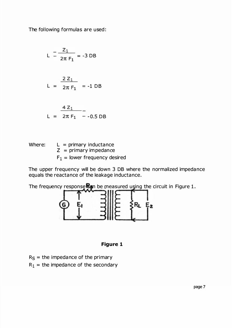
The fol lowing formulas are used :
L
L
L =
Where:
-3 DB
-1 DB
0.5 DB
L = primary inductanceZ primary im pedan eF ower frequency desired
The upper frequency will be down 3 DB where the normalized impedanceequals the reactance of the leakage inductance
The frequency response can be measured using the ci rcuit in Figure 1
Figure 1
R the impedance of the primaryR the impedance of the secondary
page 7
8/17/2019 Audio Transformer Design Manual - Robert G. Wolpert (2004)
http://slidepdf.com/reader/full/audio-transformer-design-manual-robert-g-wolpert-2004 10/117
The voltage of E1 must be he d constant for al l frequencies. The output
voltage, E is then set for a middle frequency, usually 1000 Hz and thedeviation from this voltage is the response over the frequency range.
1.2 Impedances
The impedances of both the primary and the secondary must be known orcan be calculated The impedance ratio is equal to the turns ratiosquared and also equa to the voltage ratio squared
2 2
==
1.3 Power Leve
The operating power evel is usual ly call ed out This can be sine wavepower or music power Sine wave power wi ll be approximately threetimes the effective music power
The transformer must be ab e to handle the fu l vo tage and current atany frequency within the operat ng range for sine wave power. For musicpower it must handle the full vo tage but only one third of the current forheating purposes This wil l al low the use of smal ler magnet wire and w lresult in a smal er unit
1.4 Total Harmonic Distortion
The total harmon c distortion is mainly a funct on of the operat ng fluxdensity in the core at the lowest operating frequency. Reducing the fluxdensity will reduce the distortion
The distortion at a given frequency and flux density will vary with thetype of magnetic materia used
page 8

8/17/2019 Audio Transformer Design Manual - Robert G. Wolpert (2004)
http://slidepdf.com/reader/full/audio-transformer-design-manual-robert-g-wolpert-2004 11/117
1 5 D rect Current n the W ndings
When one or more of the w ndings is requ red to carry unbalanced directcurrent, it is necessary to design that wind ng fo the proper inductance
the same way you would design an inductor carrying di rect current. Theproper air gap spacer must be put in the magnetic path Th is wi ll resultin a larger unit than one that does not carry unbalanced direct current.
1.6 Hum Reduction
When designing for low level usage, it is often necessary to keep theexternal flux fie lds at a very low level . Levels of -60 DB to 80 DBrequirements are not unusual .
his is accomp lished by enclosing the unit in a case o r cases using highpermeabil ty materials. 80°/o nickel is often used for this appl cation. Asingle case or a nest of cases using alternate cases of high permeabilitymater al and copper may be needed .
1.7 Long tudinal Ba ance
ongitudinal balance is a measure of a transfo me 's balance and abil tyto prevent longitudinal signals or signals that have been induced in thepower line from being transferred into the secondary of the transformer
1.8 Insert on Loss
Insertion loss is a measure of the power available out of the t ansformerversus the power induced nto the transforme .
page 9

8/17/2019 Audio Transformer Design Manual - Robert G. Wolpert (2004)
http://slidepdf.com/reader/full/audio-transformer-design-manual-robert-g-wolpert-2004 12/117
CHAPTER 2. LOW FREQUENCY RESPONSE
The requirements of an audio transformer are al nter - re ated and mustal l be cons ide red in the design. The first step is to design for the ow
frequency Th is wil l establi sh the size of the core and the num ber ofturns needed It is al so the easiest pa rt of the design
2.1 Open circuit inductance
Calculate the inducta nce necessary Assum ing a -3 DB requirement atthe ow frequency end, the inductance needed wi l be:
L =
For 1 DB and - 0 . 5 DB requirements, the formu a is changed according y,as called out in 1 . 1 .
It can now be seen that the higher the primary impedance, the arger theinductance needed This transl ates to a l arger core and/o r more turns Italso makes it more difficu t to obtain the higher frequency limit as wi l beseen later
2.2 Primary voltage and current
Calculate the pri ma ry voltage an d current Th is depends on theinformation given. If the power (wattage) is given an d the impedance isknown, Ohm's law may be used to calculate the vo tage and current
AND I
If the power is given in DB or DBm, the power in watts must be eithercalculated or taken from a chart. A cha rt of DB versus watts is in theAppend ix DBm is DB for a 600 ohm im pedance
page 10
8/17/2019 Audio Transformer Design Manual - Robert G. Wolpert (2004)
http://slidepdf.com/reader/full/audio-transformer-design-manual-robert-g-wolpert-2004 13/117
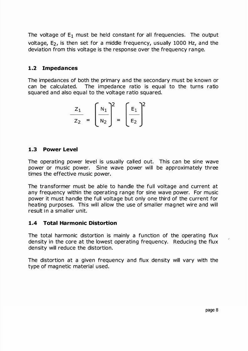
2.3 Secondary voltage and current
Calculate the secondary voltage and current h e seconda ry voltage canbe calculated from the impedance rat o By rearranging the formula from1 .2 :
he current ratios are inversely proportional to the voltage ratios so thesecondary current can be calculated by rearranging the equat on:
- =
2.4 Core size and material
he core materia l w ll depend large y on the app cation If thetransformer s a sma l, low - evel unit, the material can be either 50°/o or80 °/o nickel These a re h igh permeabil ity materia s and wi l l require fewerturns than 4°/o si licon steel If a higher level unit is desi red, 4°/o silicon
steel wil probably be the best choice as the cost of nicke la minations w llbe prohib itive in la rger units. Al so, th e operat ng flux density can behigher in sil icon steel, which wil l resu t in a sma l ler unit
he power requ irements w ll hel p choose the core size If the core size isca l led out, there is no choice If not, then exper ence from past des gns,or an adjustment to the information from the 60 Hz tables w l have to beused
For example, a 150 watt, 60 Hz core wi ll probably be about right for a
50 watt, 20 Hz aud io transformer his wi ll be a good starting point. Seethe table in the Appendix
he core s ze obta ned in this manner is an approximation andadjustments wi l l h ave to be made to get the proper fil l When the turnsar e calculated in the next step and the wire sizes are chosen, the fit inthe core can be ca culated
page 1
8/17/2019 Audio Transformer Design Manual - Robert G. Wolpert (2004)
http://slidepdf.com/reader/full/audio-transformer-design-manual-robert-g-wolpert-2004 14/117
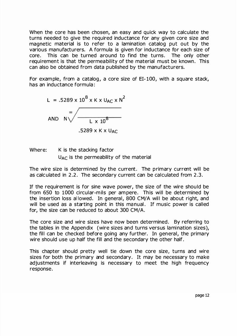
When the core has been chosen, an easy and quick way to calculate theturns needed to give the required inductance for any given core s ze andmagnetic materia is to refer to a lamination catalog put out by thevarious manufacturers A formula is given for inductance for each size ofcore Th is can be turned around to find the turns The only otherrequi rement is that the permea bi ity of the material must be known Thi scan also be obtained from data published by the manufacturers
For exam ple, from a catalog, a core size o EI- 100, with a square stack,has an inductance formula :
Where:
2L = . 5289 x 10 x K x UA c x N
AND N L x 10
5289 x K x UA c
K is the stack ng factorUA c is the permeabil ty of the material
The wire size is determi ned by the current The p rimary current w l l be
as calculated in 2 2 The secondary current can be ca culated from 2 3
If the requ rement is for sine wave power, the s ze of the wire shou d befrom 650 to 1000 ci rcular-m il s per am pere Th is wi l be determined bythe nsertion loss al owed In genera l , 800 CM/ A wil be about r ght, andw llbe used as a starting point in this ma nual If mus c power is cal edfor, the size can be reduced to about 300 CM/A
The core size and wire sizes have now been determined By re erring tothe tables in the Appendix (wire sizes and turns versus lami nation s zes),
the fil l can be checked before going any further In genera l , the prima rywire should use up half the fil and the secondary the other half
This chapter should pretty wel tie down the core size turns and w resizes for both the primary and secondary It may be necessary to ma keadjustments if interleaving is necessary to meet the h gh requencyresponse
page 12

8/17/2019 Audio Transformer Design Manual - Robert G. Wolpert (2004)
http://slidepdf.com/reader/full/audio-transformer-design-manual-robert-g-wolpert-2004 15/117
CHAPTER 3. HIGH FREQUENCY RESPONSE
The limit of the high frequency response is control ed by the eakageinductance and the impedances.
The leakage inductance i s proport onal to th e square of th e turns, thus, itis possible to reduce this value greatly by reduc ng the turns, but sincethe lower frequency limit depends on the primary inductance and that iscontrolled by the turns and the type of magnetic mater al used in thecore, the turns are pretty wel l set Also, care must be taken that thema ximum flux density of the material s not exceeded in reduc ng theturns . The leakage can be reduced by interleaving the pr mary andsecondary windings.
3 1 Interleaving the winding
As ment oned before, the high requency response is determ ned by theleakage inductance and the wind ng impedances.
In order to reduce the leakage inductance, it s sometimes necessary tointerleave the windings . That is, sp lit the windings and wind one partprimary, one part secondary, one part primary, etc Th is can resu t in1 :2 2: 3 3 4 etc, interleaving.
The exam ples wi ll show des gns with thi s interleaving used . A 3:2interleave would be 1/3 primary, 1/2 secondary, 1/3 primary, 1/2secondary and 1/3 primary, and so on In some cases interleavings of5:4 6:5 and more are used
3 2 Leakage inductance
The leakage inductance of a transformer can be calculated in many ways.Some of these are extremely comp icated .
A good compromise for a transformer that is wound concentrica ly, that isone winding over the other, is the following :
L =0 6x N x M T x (2 x S x T + ) = HYS
5 x WL x 09
page 13
8/17/2019 Audio Transformer Design Manual - Robert G. Wolpert (2004)
http://slidepdf.com/reader/full/audio-transformer-design-manual-robert-g-wolpert-2004 16/117
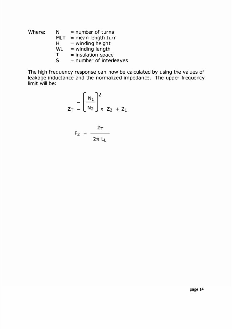
Where: NMLHWLTs
= number of turns= mean length turn= winding heigh t= winding length
= insulat on space= number of inte leaves
The high frequency response can now be calculated by using the values ofleakage inductance and the normalized im pedance . The upper frequencylimit will be
2
ZT -
[ ]x Z2 + Z1
page 14

8/17/2019 Audio Transformer Design Manual - Robert G. Wolpert (2004)
http://slidepdf.com/reader/full/audio-transformer-design-manual-robert-g-wolpert-2004 17/117
CHAPTER 4. SPECIAL REQUIREMENTS
4 1 Tota harmonic distort on
If THD is called out, the flux density in the core and the type of corematerial must be considered . This may require the co re size or turns orboth be modified .
The distortion is normal y only of concern at the lowest frequency as itfalls off rapidly as the frequency increases.
If you consider the th ree most commonly used types of materials, 80°/nick el , 50°/ nicke l, and si l con steel , the flux densities wil l vary from thelowest for the 80°/ nickel to the h ighest for the si l icon steel . A table inthe Appendix will give some representative values for the three materialsat various flux level s These numbers wil al low you to est mate thedis tortion that can be expected at the flux level and frequency ofoperation.
4.2 Sh elding for hum reduct on
Many low level transformers are requ red to function within an externalfield without picking up that field and transmitting it into the operatingcircuit.
The transformer can be enclosed within a case or cases to achieve thedesired results . For exam pl e, a sing le case of steel wil l give about 10 DBof sh ie ld ing A case made of 50°/ nickel wil l give about 20 DB. A casemade of 80°/ nicke wil l g ive 30 DB A nest of cases consisting of an80°/ nickel case, a copper case and anothe r 80°/ n ckel case wil l g ive60 DB of shielding. If th is is extended to th ree 80°/ n ckel cases with twocopper cases in between, it wil g ve 90 DB of shie ding.
These 80°/ nickel cases must be properly annealed and the copper casesmust be soft copper to obtain the desired results.
Care must be taken that the external field is not so high as to saturatethe 80°/ nickel o r the expected results wi l l not be obtained . If thisoccurs, a stee case on the outside may be used to reduce the field to alevel that can be tol erated .
These methods wi ll also apply when the transform er is placed in a verysensitive circuit and the external f ux of the transformer must be reduced
© 1989, ROBERTG. WOLPERT Rev.2004 page 15
8/17/2019 Audio Transformer Design Manual - Robert G. Wolpert (2004)
http://slidepdf.com/reader/full/audio-transformer-design-manual-robert-g-wolpert-2004 18/117
4.3 Long tudinal balance
A longitudina signal is one that is induced along the power lines andenters the transformer in both the primary leads as if they were one lead .This signal must be prevented from passing through the transformer as asignal in the output.
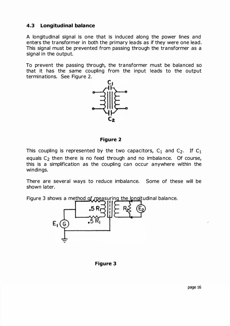
To prevent the passing through, the transformer must be balanced sothat it has the same coupling rom the input eads to the outputterminations See Figure 2
F gure
This coupling is represented by the two capac tors, C 1 and C 2 I c 1
equals C 2 then there is no feed through and no im balance Of course,this is a simplification as the coupling can occur anywhere within the
windings.
There are several ways to reduce imbalance. Some of these will beshown later.
Figure 3 shows a method of measuring the longitudinal balance.
,5Ra
gure 3
page 16

8/17/2019 Audio Transformer Design Manual - Robert G. Wolpert (2004)
http://slidepdf.com/reader/full/audio-transformer-design-manual-robert-g-wolpert-2004 19/117
.5 R1 + 5 R = primary Z and must be matched to with in 0 . °/ for a
40 DB balance and to be within 0 . 0 1°/ if 60 DB of balance is required . R2will be equal to the impedance of the secondary. he core shou d beconnected to g round If a sh ie ld is used it should be connected to thecore and ground
E2 shou d be a voltmeter with a DB scale. Perfect balance will be when
E2 reads zero When measuring E2, there should be no voltmeter
connected to read Ei Short direct wiring should be used to minimizecapacitance unbalance. The level of E should be the operating level of
the transformer, or as called out by the customer.
4.4 Insertion loss
The insertion loss of a transformer is a measure of the efficiency as itshows how much power is consumed by the transformer. Thus, it isim portant to keep these losses as low as possib le
he most obvious of these losses i s the DC resistance of th e windings .he larger the size of the wire that can be used, the ower the losseshe losses in the magnetic material can also contri bute to the total losshe magnetic material losses can usually be ignored if the flux density is
kept within reasonable limits.
The following method can be used to determine the approximate insertionloss before bui lding the unit. The total or normal ized winding res stance,that is the resistance of the secondary referred to the primary, or theprimary referred to the secondary, w l norma ly be 10 to 20°/ of the loadresistance If it is 1 0°/ , it wi l l have a loss of approximately 0 . 5 DB and, if20°/ , it will be approximately 1.0 DB.
By using the calculated values of the winding resistances, the ca culation
of the normalized resistance can be done as fol ows:
2
page 17

8/17/2019 Audio Transformer Design Manual - Robert G. Wolpert (2004)
http://slidepdf.com/reader/full/audio-transformer-design-manual-robert-g-wolpert-2004 20/117
Then the percentage loss will be:
Where:
100
Ri - DC resistance of the primary windingR2 = DC resistance of the secondary winding
Figure 4 shows how to measure the insert on loss
Where
Figure 4
E Voltage across the primaryE2 - Load voltageRi = Prima ry i mpedanceR2 Secondary i mpedance
It should be noted that the insertion loss test circuit is the same as thefrequency response circuit, except that the primary voltage is taken afterthe primary resistor instead of across the generator.
Then the insertion loss is
20 LOGEi
E2 �
The vo tages obtained from this test can be used to ca culate the insertionloss at any given frequency
page 18
8/17/2019 Audio Transformer Design Manual - Robert G. Wolpert (2004)
http://slidepdf.com/reader/full/audio-transformer-design-manual-robert-g-wolpert-2004 21/117
CHAPTER 5. DESIGN METHODS
Before the design of any transformer can begin, it is necessary tounderstand the general construction and how to calculate the turns,winding fill and DC resistances of the winding.
The following will show the methods used to determine these values
5.1 Flux density
The formula for calculating the open circuit primary inductance needed tomeet the low frequency response is given on page 7. In this formula, noprovision is made for the flux density. It is always necessary to calculatethe flux density to be sure that t e core will not be operating in saturationand adjustments made to t e turns, if necessa y. T i s may result inmore turns than the minimum needed fo the requi red inductance Theresulting inductance may be hig er than is necessary.
The operational flux density for the various core materials can beobtained from a core manufacturer's catalog . or the purposes of th ismanual, the maximum flux densities used will be 17 kilo gauss for 29M6material 8 k il o- gauss for 50°/ nickel and 5 ki lo -gauss for 8 0°/ nickel Ifother materials or flux densities are desirable, the literature should beconsulted
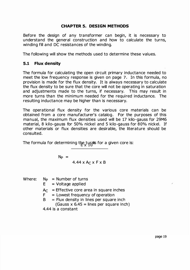
The formula for determining the turns for a given core is:
N =4. 44 x A x F x B
W ere: N = Num ber of turnsE = Voltage appl ied
A = Effective co e a ea in square inchesF = Lowest frequency of operationB = Flux density in ines per square inc
(Gauss x 6.45 = lines per square nch)4 44 is a constant
page 19

8/17/2019 Audio Transformer Design Manual - Robert G. Wolpert (2004)
http://slidepdf.com/reader/full/audio-transformer-design-manual-robert-g-wolpert-2004 22/117
5.2 Construction suggestions
The construction of an audio transforme differs from a regular powertransformer in that the leakage inductance must be kept as low aspossible
The interleaving has been covered for the leakage inductance, but theadvantages of interleaving can be offset by improper or s oppy winding.The windings must be d irectly above one another The marg ins cal led outmust be ma intained and the winding lengths must be ful ly uti li zed . If theturns are not sufficient to fill out the winding length, then the wire mustbe spiraled to fill it out The margins for a l l windings must be the sameIf one size wire calls for a 1/4" margin, for instance, then all windingsmust have 1/4" margins
The windings, when layer -wound, must be even and no cross-oversa llowed . In bobbin windings, they cannot be in perfect layers, but theyshould be wound as evenly as possible.
In general, good, high quality workmanship is essential for an audiotransformer to meet the design goa ls . No m atter how good the design is,sl oppy construction techniques can result in a fai led transformer.
These methods should be called out in the construction specif cations
5.3 Calculating the physical parameters
The fol lowing design exam ple is for a si mp le power transformer. This isused in order to conserve space It will d em onstrate the principles usedfor calcu lations of the turns, winding fil l and DC resistances of the magnetwire the same as for an aud o transformer
It is desired to design a transformer to operate from a 1 15 volt line at60 Hertz and to del iver 6 . 3 vo ts at 1 0 am pe res AC. The ph ysica l size isnot g iven
page 0
8/17/2019 Audio Transformer Design Manual - Robert G. Wolpert (2004)
http://slidepdf.com/reader/full/audio-transformer-design-manual-robert-g-wolpert-2004 23/117
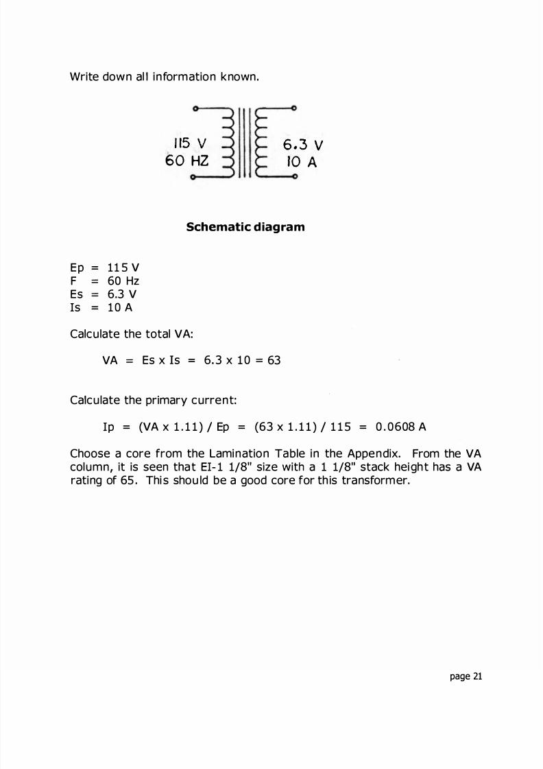
Write down al information known
5 v60 HZ
.3 10 A
Schematic diagram
Ep = 11 5 VF = 60 HzEs = 6.3 V
s = 1 0 A
Calculate the total VA:
VA = Es x Is = 6 3 x 1 0 = 63
Ca culate the primary current:
p = (VA x 1 . 1 1 ) Ep = (63 x 1 1 1 ) 1 1 5 = 0 . 0608 A
Choose a core from the Lamination Table in the Appendix From the VAcolumn, it is seen tha t E - 1 1/8" size wit a 1 1/8 stack height has a VArating of 65 Thi s should be a good core for th is transformer.
page 21
8/17/2019 Audio Transformer Design Manual - Robert G. Wolpert (2004)
http://slidepdf.com/reader/full/audio-transformer-design-manual-robert-g-wolpert-2004 24/117
The manufacturers will g ve the core losses at flux densities in kilo-gaussThis can be converted to lines by multiplying by 6.45.
For example, 15 KG or 1 50 00 gauss x 6. 45 = 96750 lines
The conversion can be done directly in the formula for primary turns byusing the gauss number and adding the 6.45 factor below the l ne
The window of the l am ination is 9/16" x 1 1 1/16" . The effective corearea is 1 164 square inch
We wi ll choose to try 29M6 g rade la minations with a flux density of 95000l ines as a starting point Thi s is 14. 72 KG.
Calculate the primary turns
11 5 x 10N = = 390 T
4 44 x A x F x B 4.44 1.164 60 x 95000
Calculate the secondary turns
Ns Np / Ep x 1 .0 5 x Es = 390 / 11 5 x 1. 05 x 6 3 = 22. 4 turns
Change the turns to an even number or 22 turns
Choose the w re sizes
The primary wire should be .608 x 800 circular mils = 486.4. For this wewil l see that #23 wi re is the closest with 5 09 5 cm See Wire Table in theAppendix
The secondary w re should be 10 x 80 0 cm 800 0. # 1 1 wire has8234 cm and wil l be used It should be noted that this is conservativeand in practice there is room for adjustment up or down, if needed Theonly limiting factors will be temperature rise and regu ation
page 22
8/17/2019 Audio Transformer Design Manual - Robert G. Wolpert (2004)
http://slidepdf.com/reader/full/audio-transformer-design-manual-robert-g-wolpert-2004 25/117
Calculate the turns per layer and number of ayers
The window length is 1 1 1/16" long n order to fit, the coi l length shouldbe 1/1 6" sho rter or 1 5 /8" long From the wire tab e, it is seen tha t themar gin for #23 wi re should be 1/8" on each end The margin for # 1 1wire should be 1/4" on each end The turns per layer is determined by
the winding length x the turns per inch for tha t wi re size This is al soobtained from th e wire table The va lues sh ould be put down on the worksheet clearly to show the construction of the coil
With a coil length of 1 5/8", the winding length for #23 wire will be 1 3/8"and a margin of 1/8" on each end
he turns per layer wil be:
1 3/8" x 37 4 (turns per inch from tab e) = 52 turns
Layers 390 / 52 = 7 . 5 layers Use 8 .#11 wire winding length = 1/8", margins 1/4" each endTurns per laye r 1 1/8" x 1 0. 2 = 1 1 turnsLayers = 22 1 1 = 2
It should be noted that for a power transformer, the margins of thewindings do not h ave to be the same for al l wind ings
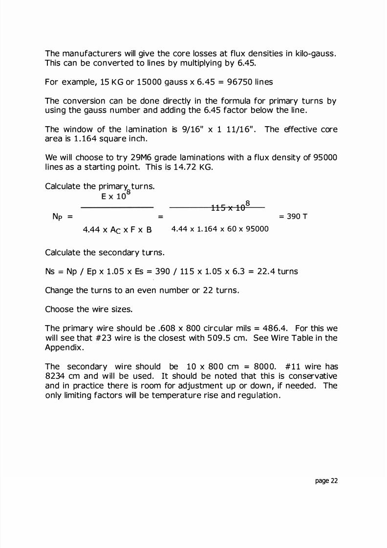
Figure 5 sh ows the cross section of a coi l with 4 la yers The spacebetween the layers is, for practica purposes, the layer insulation and the
im pregnating compound The mean length turn is the distance a roundthe winding at the center See Figure 6. n Figure 6, the mean engthturn would be between layers 2 and 3.
�
lM T
Figure 5 Figure 6
page 23

8/17/2019 Audio Transformer Design Manual - Robert G. Wolpert (2004)
http://slidepdf.com/reader/full/audio-transformer-design-manual-robert-g-wolpert-2004 26/117
Calculate the fil l of the window This is done by add ing up al l the variousthicknesses of winding tube, wire diameter, layer insulation andwrappers. The layer insulation is determined by the thickness needed tosupport tha t particula r wi re size This is ca ll ed out in the Wire Table inthe Appendix.
The winding tube thickness is determined by what is needed to supportthe coi l . Smal l coi s with fine wi e need ess support than la rger coi s withheavy wi re his can vary from . 020 to 070 or more. A coi fo thesize used in this example wi generally use a winding tube thickness of. 030" to 040"
he wrapper is th e insulation used between windings . This is determinedby the voltage isolation needed and the support needed for the nextwinding For thi s exam ple we wil l use 0 0" thick insulation, as this is thevalue needed to support the # 1 1 wire and, since there are no unusual lyhigh voltages involved, it will be used.
It is now necessary to put down on paper the various thicknesses, addthem up and calculate the percentage of availab e space in the windowthat is needed
This lam ination h as a window width of 9/16" or, in decima s, 5625"
Figure 7 shows the s ze of the lam at on (E -112)
1"3 DIA. HOLES
•
�-C
l
�
Figure 7
S I- f
r
page 24

8/17/2019 Audio Transformer Design Manual - Robert G. Wolpert (2004)
http://slidepdf.com/reader/full/audio-transformer-design-manual-robert-g-wolpert-2004 27/117
The fil l can now be calcula ted :
Winding tube8 layers #23Layer insWrapper
2 layers #11Layer insWrapper
Total fill
= 0400= 1920= 0210= 0100
= .1858= .0100= .0100
4688 . 5625 x 1 0 0 = 8 3 3°/
This is an acceptable fill.
The voltage d rops and resistances can now be ca lculated In order toobtain the voltage drops in each winding, it is first necessary to picture
the bu ld up of the coil as calculated above in the fil l . This build -up isaccomp lished in the fol lowing order:
1 Winding tube2 Prima ry wi e sep arated by the laye r insulation3 Wrapper between windings4 Secondary wire separated by the layer insulation5 Fina l ly, t he outside wra pper
The mean length turn can be determined by taking the build-up and
adding up the va rious sections.Figure 8 shows a view o f the tube upon which the w ire is wound .
. 040"
1 1 /8"
1 1/8,,040
Figure 8
page 25
8/17/2019 Audio Transformer Design Manual - Robert G. Wolpert (2004)
http://slidepdf.com/reader/full/audio-transformer-design-manual-robert-g-wolpert-2004 28/117
n order to simplify the calculations it is advisable to reduce the windingtube to a squa re if it is not a l ready one This is done by taking the tota ldistance around and dividing it by 4. This wi l l give an equivalentdimension of one side only.
For example, a winding tube that is 1 1/2" x 1 3/4 would be:
1 1/2" x 2 + 1 3/4 x 2 3 + 3.5 = 6 5 4= 1 625 equivalentsquare.
n the example used the winding tube is already a square so the 1 1/8"dimension will be the starting point.
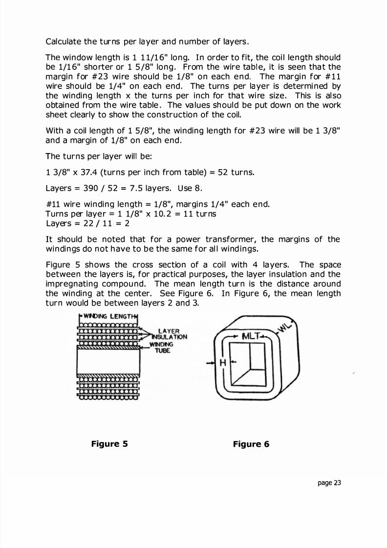
Starting with the size of the lamination and adding the winding tubethickness to each side, the actual dimension of the winding form will beobtained. The wire and insulation is added on top of th is .
LaminationTube x 28 #23 wireInsulation
= . 1250 (1 1/8")0800
= 1920= 0210
Total 1 4180
Thi s gives the build-up in one di rection of the primary winding . When th s
number is mu tiplied by 4, it will give the length of one turn in the centerof the winding, or the mean length turn of the pri ma ry wire Thus,1.4180 x 4 390 x 1.6966 1000 3 . 75 Ohms. The 1 .6966 is theresistance of this size wire per 1000 inches.
t should be noted here that this mean length turn value is used in thecalculation of the winding leakage inductance of an audio transformer
The value, 1 4180, is the bui d-up to the center of the primary winding,so the primary values must be added in again to get to the start of the
secondary winding . The entire build-up i s now repeated to clearly showthe calculations.
page 26

8/17/2019 Audio Transformer Design Manual - Robert G. Wolpert (2004)
http://slidepdf.com/reader/full/audio-transformer-design-manual-robert-g-wolpert-2004 29/117
Lam.Tube8 - #23Insul
= 1 1250.0800.1920
= 0210
8 - #23 =
1 .41 80 x 4 x 390 x 1 .6966 1 00 0 = 3 . 75 x .608 = 2.28 v
1920Insul = . 0210Wrap .01002 # 11 = .1858Insul .0100
1 .8368 x 4 x 22 x . 1 05 0 1 00 0 = .0169 x 10 = .169 v
These values can be used to determine the output voltage under loadedconditions This i s done by subtracting the p rimary voltage d rop from theinput voltage and, from the turns ratio, obtain the secondary voltage.The secondary voltage drop is then subtracted from this value to obtainthe loaded voltage.
115 - 2.28 = 1 12. 72 v
This is the effective input vo tage.
rom the turns ratio, 1 12 . 72 / 390 x 22 = 6 358 V
Subtracting the secondary voltage drop, 6. 358 . 169 = 6. 189 V
This is lower than the 6. 3 V desired so adjustments must be made. Thiscan be done by adjusting either the primary turns down or the secondaryturns up This wi ll not be carried any further as the purpose of thisexample is to show how to ca culate the fi and the resistances of thewindings.
The weight of the wire can be obtained by using the DC resistances.
Referring to the wi re table, the weights are given in Oh ms per pound.
For example, #23 wire is 12.88 Ohms per pound
Then the weight is 3 75 / 12 .88 = .291 pounds.
page 27
8/17/2019 Audio Transformer Design Manual - Robert G. Wolpert (2004)
http://slidepdf.com/reader/full/audio-transformer-design-manual-robert-g-wolpert-2004 30/117
As indicated previously, th s example was used only to show the methodsof calculating the winding layers, turns per layer, fill and DC resistance.It can also be used as a guide for designing power transformers.
The complete design and construction of power transformer and inductorscan be found in the TRANSFORMER DESIGN AND MANUFACTURINGMANUAL publi shed by the author in 1984.
The methods described above will be used in the fo lowing examples ofaudio transformers.
page 28

8/17/2019 Audio Transformer Design Manual - Robert G. Wolpert (2004)
http://slidepdf.com/reader/full/audio-transformer-design-manual-robert-g-wolpert-2004 31/117
PART II. DESIGN EXAMPLES
page 29
8/17/2019 Audio Transformer Design Manual - Robert G. Wolpert (2004)
http://slidepdf.com/reader/full/audio-transformer-design-manual-robert-g-wolpert-2004 32/117
PART II . DESIGN EXAMPLES
In the actua l design of an audio transformer it s necessary to consider al lof the requirements one at a ti me However, m any of these requirementsinteract and this will affect the results so they must all be kept in mindwhile doing the design.
The exam ples th at fol low wil l cover a broad range of aud io transformers.Some of them wi ll be relative y easy to design and some wi ll be moredifficult and time consuming.
An attempt will be made to go through each design, step-by-step,explaining the thi nking as the design progresses
The calculations of the various parameters wil be given and then theactual transformer wil l be buil t and tested The results wi l be com paredwith the calculated values
In order to demonstrate the results of interleav ng , a design for a 600watt transformer has been made and built for a 4 Ohm to 200 volt linetransformer
The com plete design wi ll not be shown as the fo lowing designs wi lthorough ly de monstrate the design and construction of enough types ofaudio transformers to suf ice.
The lamination size is El- 2 1/8" w th a 2 1/8" stac k. The first design wasnot interleaved It was bui lt with the p rimary first and then thesecondary
The h igh frequency response was ca culated to be down 3 DB at 9600 Hz.The measured response was down 3 DB at 1 1000 Hz.
The unit was then redesigned and buil t with a 2: 1 interleaving . Thesecondary was split in half and the primary was put in the center.
The calculated 3 DB down-point was 26400 Hz and the measuredfrequency was down 3 DB at 30000 Hz.
The low frequency response was not af ected.
The following designs have been chosen to demonstrate the three mostrepresentative types of audio transformers.
page 30

8/17/2019 Audio Transformer Design Manual - Robert G. Wolpert (2004)
http://slidepdf.com/reader/full/audio-transformer-design-manual-robert-g-wolpert-2004 33/117
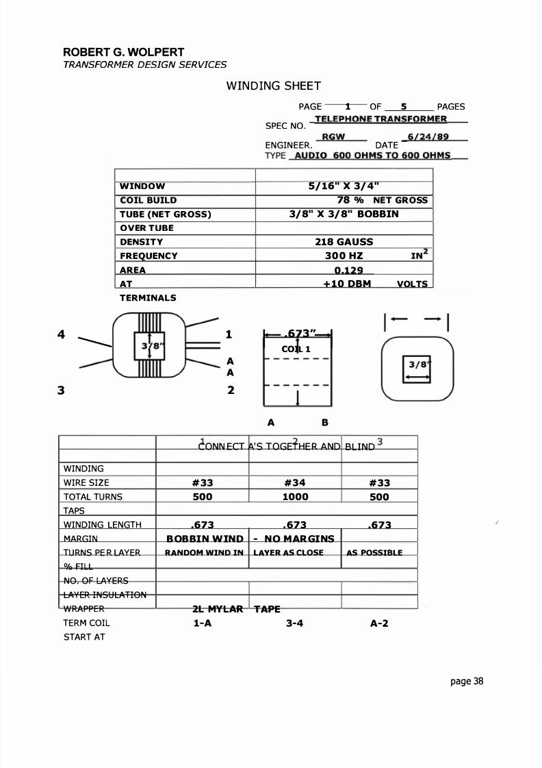
EXAMPLE 1: VOICE FREQUENCY TELEPHONE TRANSFORMER
This example will be for an audio transformer used in a telephone circuitthat has a voice frequency response requirement
60 OHMS
40-
5
600 S
.e
C rcuit D agram
The pola rity dots indicate the instantaneous pola r ty o the windings. Thisis important in many audio transformers
he specifications call for the fol owing
Impedances are 600 Ohms to 600 OhmsFrequency response is ± 1 0 DB from 300 Hz to 3500 H zInsertion oss is 1 0 D B max imumLongitud inal ba lance is 60 DB m inimum from 2 0 Hz to 1 00 0 Hz and
40 DB at 400 0 HzOperating level is + 10 DBM
H D at 300 Hz = 0 5° maximumPrimary DC current is . 090 a m peresPhysica l size is g iven as EI- 3/8" lam ination with a squa re stack to be
wound on a printed circuit bobb nPrimary DC resistance 5 0 Ohms maximumSecondary DC resistance = 65 Ohms maximum
From page 7, the inductance needed is:
L =z 600= = 636 HY F x 300
© 1989, ROBERTG. WOLPERT, Rev.2004 page 31

8/17/2019 Audio Transformer Design Manual - Robert G. Wolpert (2004)
http://slidepdf.com/reader/full/audio-transformer-design-manual-robert-g-wolpert-2004 34/117
The design for turns on the primary is done the same as for aninductance that ca rries di rect cu rrent Any method for obtaining theproper result is satisfactory
In this case Hanna s curves were used to calculate the turns and air gapneeded to obtain the proper inductance.
This transformer can be constructed using e ther 29M6, 50°/ n ckel or80°/ nicke l. 29M6 is th e pre erred choice, i it wi l resu t in th e properinductance and the wire sizes wil meet the specification for resistance,because it is the least expensive
29M6 will be chosen to start the turns calculations. From Hanna s curvesfor 29M6 core ma terial, th e turns wi ll be 10 00 and the g ap spacer neededis 005 .
Since the gap spacer is put across both legs and the center E, the spaceris di vided by 2 for a thickness of 0 025 ". A spacer of 00 3 wil l be used tosta rt as this is a standard th ickness of insu lating pa per. This va lu e mayhave to be adjusted when the unit is tested.
The f ux density in the co re must be checked . +1 0 DBM ( 1 0 DB n 600Ohms ) i s the power level . By checking the DB Expressed in Watts Ta blein the Appendix, the power level is seen to be 0 1 watts The voltage is :
E = . 1 x 600 = 2.45 V
The flux density i s ca lcu ated :
2 45 x 10B =
�4 44 x .1336 x 300 x 1000
= 1376 lines 213 gauss
This is a low f ux density In general , when using Hanna's curves, it isnot necessary to calculate the flux density as they are designed to keep itwithin the proper range
The curves in the Total Harmon c D stort on Table in the Appendix showthe expected THD for th is materia l and fl ux dens ty. They sh ow that theTHD wi ll be less than . 03°/ . This is lower than the requ i red 0 . 5°/
page 32

8/17/2019 Audio Transformer Design Manual - Robert G. Wolpert (2004)
http://slidepdf.com/reader/full/audio-transformer-design-manual-robert-g-wolpert-2004 35/117
The current s 01 watts divided by 2.45 V, which is .004 amperes
The 090 ADC n the primary and the required resistance w ll determinethe w re s zes to be used :
.09 x 0 . 7 = 063 (0 7 is 700 CM/A)
From the Wire Table in the Append x, #32 AWG can be used, however,the customer has called out the DC resistance and to meet th srequirement, the EI 375 Laminat on turns table shows that #33 AWG willfit and sh ou ld m eet the res stance requ irement #34 AWG w ll b e usedfor the secondary.
It can be seen from these calculations that 29M6 material wil meet theinductance and OCR requirements.
The frequency response wil not be d fficu t to meet, but the longitudinalbal ance must be considered This wil l cal for spl itting the primary in twoparts as a 2: 1 nterleave This wi ll be wound on a bobbin as requ ired bythe customer.
The follow ng calculat ons are explained in Section 5 3 Calculating thephysical aram t rs.
The fi l w l l not be calculated :
The window of the amination is 5/16 x 3/4"The winding ength of the bobbin is .673" (from manufacturer's cata log)
#33 wire turns per layer = 75 layers = 500 / 75 = 6 66 (use 7)
#34 wire turns per layer = 84 layers = 1000 / 84 = 1 1 .9 (use 12)
Bobbin7- #33Wrap12 #34Wrap7- #33Wrap
= 0300= 0553= .0060= .0840= 0060= .0553= .0060
.2426 3 125 = 776 x 10 0 = 78° f ll
page 33

8/17/2019 Audio Transformer Design Manual - Robert G. Wolpert (2004)
http://slidepdf.com/reader/full/audio-transformer-design-manual-robert-g-wolpert-2004 36/117
Ca lculating the DC resistances .
. 3750
.0600
.0553
4903 x 4 x 500 / 1000 x 17.2416 16.9 Ohms055300600840
6356 x 4 x 10 00 / 10 00 x 2 1 . 7416 55.27 Ohms0840
.0060
.0553
.7809 x 4 x 500 I 10 00 x 1 7.2416 = 26.92 Ohms
This is 16.9 + 26.92 = 43 .82 Oh ms tota l for th e pr m ary, 55. 27 Oh ms forthe seconda ry . These are in conform ity with the requirements
The customer ca l ed for a 1: 1 turns ratio so the tu rns cannot be adjusted.
The insertion loss is calculated using the formula from page 17:
2
Since the turns are equal, the first value becomes 1
page 34

8/17/2019 Audio Transformer Design Manual - Robert G. Wolpert (2004)
http://slidepdf.com/reader/full/audio-transformer-design-manual-robert-g-wolpert-2004 37/117
Then:
R = R2 + Ri = 55.27 + 43 82 = 99.09
IL = RTz
= 99 09600
X 100 = 16 5°/
f thi s is interpolated it wi l l be 75 DB for 15°/ , so it is a pproximately82 DB for 16 5 °/ . The requi rement of 1 . 0 DB wi ll be met See page 1 7.
The next requ irement to be considered i s the long itud inal ba lance. This isa small transformer with impedances of 600 Ohms for both windings.The size and the low impedance makes it easier to meet the
requirements.
There is no easy way to calculate the ongitudina balance so pastexperience mu st be ca l led on A 2: 1 interleave has been chosen Thehigh frequency response is only 3500 Hz so that should be no problemand can be met without interleaving but the balance will require thatvoltage gradients be considered.
The 2: 1 interleave wi l sp li t one winding so that the voltag e g rad ient oneach side of the center winding is small
.s
ov ov I V I
f the start of the primary winding is 0 volt and the finish is 1 volt and thesecondary will be the same since they have the same number of turnsthen the center of the primary will be 0.5 volt to 0 volts on the start ofthe secondary and a so 0 5 volt to 1 volt to the finish of the secondary.
This wil result in a difference of 0.5 volt from the primary to both thestart and finish of the secondary. This wi ll provide a fai rly equal voltagegrad ient Of cou rse there a re other paths that can upset a perfectbalance for example from windings to core and the dressing of theleads
page 35
8/17/2019 Audio Transformer Design Manual - Robert G. Wolpert (2004)
http://slidepdf.com/reader/full/audio-transformer-design-manual-robert-g-wolpert-2004 38/117
Another way to increase the balance is to put shields in between thewindings and connect these to g round . A further increase can beaccomp ished by putting in additional shields and using box shields thatcompl ete y enclose both windings . These methods are used in instrumenttransformers, where maximum isolation is necessary.
This interleaving wil result in a frequency response much higher thanrequi red for thi s transformer
The frequency response can now be ca lcu ated
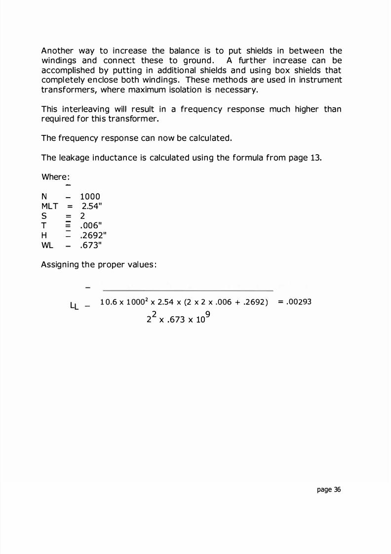
The leakage inductance is calculated using the formula from page 13
Where:
N - 1000MLT = 2.54"s = 2T = 006H - 2692"WL - 673
Assigning the proper val ues:
L 10.6 x 1000 x 2.54 x (2 x 2 x .006 + 69 ) = .00293L -
2 2x 673 x 10
9
page 36
8/17/2019 Audio Transformer Design Manual - Robert G. Wolpert (2004)
http://slidepdf.com/reader/full/audio-transformer-design-manual-robert-g-wolpert-2004 39/117
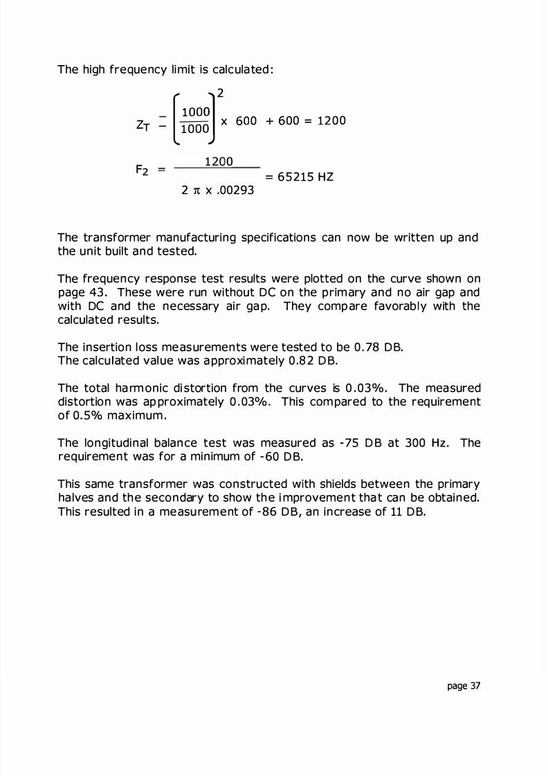
The high frequency limit is calcula ted :
z T _
[ 2
x 6 0 0 + 6 0 0 = 1 2 0 0
- - _= 65215 H Z
2 x .00293
The transformer manufacturing specifications can now be written up andthe unit built and tested.
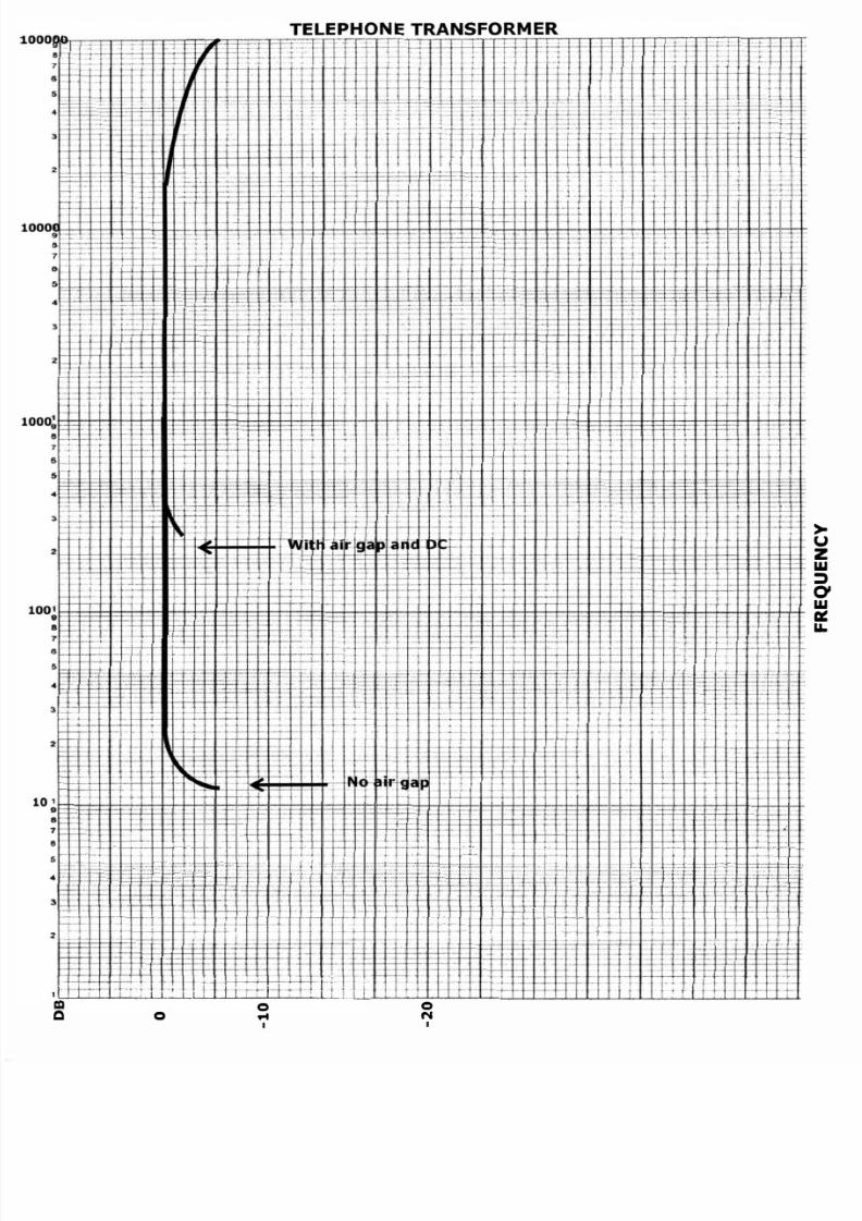
The frequency response test results were plotted on the curve shown onpage 43 These were run without DC on the p rim ary and no air gap andwith DC and the necessary ai r ga p. They comp are favorab y with thecalculated results.
The insertion loss measurements were tested to be 0 . 78 DB.The calcu ated val ue was a pproxi mately 0 .8 2 DB.
The total ha rm onic di stortion from the curves is 0 03°/ The measured
distortion was ap proximately 0 . 03°/ . This com pared to the requirementof 0 5°/ maximum
The longitudinal balance test was measured as - 75 DB at 300 Hz. Therequirement was for a minimum of -60 DB
This same transformer was constructed w th shields between the primaryha lves and th e secondary to show th e i mprovement tha t can be obtainedThis resulted in a measu rement of - 86 DB, an increase of 11 DB
page 37
8/17/2019 Audio Transformer Design Manual - Robert G. Wolpert (2004)
http://slidepdf.com/reader/full/audio-transformer-design-manual-robert-g-wolpert-2004 40/117
ROBERT G. WOLPERTTRANSFORMER DESIGN SERVICES
WIND NG SHEET
WINDOW
COIL BUILD
TUBE (NET GROSS)
OVER TUBE
DENSITY
FREQUENCY
AREAAT
TERMINALS
4 -
3
1
AA
2
PAGE OF - PAGES
SPEC NO. TELEPHONE TRANSFORMER
E GINEER. RGW DATE 624
TYP AU DIO 60 OHMS TO 60 OHMS
5/16" x 3/4"78 /o NET GROSS
3/8" X 3/8" BOBBIN
218 GAUSS300 HZ
0 129+10 DBM
r .673"-COI 1
A B
INVOLTS
CONN EC A'S OGETHE R AND BLIND
WI DI G 1 3
WIRE SIZE #33 # 3 4 #33 TOTAL TUR S 500 1000 500 TAPS
WI DING LE GTH 673 .673 673MARGI BOBBIN WIND NO MARGINS
TURNS PE R LAYER RANDOM WIND IN LA YER AS CLOSE AS POSSIBLE
% I L
NO OF YERS
LAYER I SULATIO
WRAPPER 2L MY AR TAPE TERM COI 1 A 3-4 A 2START AT
page 8

8/17/2019 Audio Transformer Design Manual - Robert G. Wolpert (2004)
http://slidepdf.com/reader/full/audio-transformer-design-manual-robert-g-wolpert-2004 41/117
ROBERT G. WOLPERTTRANSFORMER DESIGN SERVICES
MATERIAL S HE ET
PART NO.CORE EI - 3 / 8 "
29M6COPPER#33 MAGNET WIRE
3 MAGNET WIRE
CAN
LID-
LID-B
ERMINALS
BOBBIN 3/8 x 3/8
TERM BOARD
LUG PANEL
BK 3/8" x 3/8"HORIZ. FRAME
LEADS#22 SLW x 7"
LONG
#1 BLACK#2 BROWN#3 RED#4 GREEN
NOTES:
PAGE 2 OF PAGES
SPEC NO. T L PHON T NSFORM R
AM O PRICE TO PRICE O PRICE.110#
.03
.026#
1
1
1111
page 39
8/17/2019 Audio Transformer Design Manual - Robert G. Wolpert (2004)
http://slidepdf.com/reader/full/audio-transformer-design-manual-robert-g-wolpert-2004 42/117
ROBERT G. WOLPERTTRANSFORMER DESIGN SERVICES
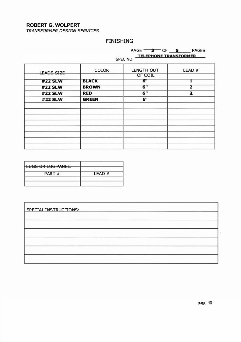
F N SHING
LEADS SIZECOLOR
#22 SLW BLACK
#22 SLW BROWN
#22 SLW RED
#22 SLW GREEN
LUGS OR LUG PAN EL
PART# LEAD#
SPECIAL INSTRUCTIONS:
PAGE 3 OF _ PAGES
SPEC NO. TELEPH ONE TR NSFORMER
LENGTH OUT LEAD#OF COIL
6" 1
6" 2
6" 3
6"
page 40

8/17/2019 Audio Transformer Design Manual - Robert G. Wolpert (2004)
http://slidepdf.com/reader/full/audio-transformer-design-manual-robert-g-wolpert-2004 43/117
ROBERT G. WOLPERTTRANSFORMER DESIGN SERVICES
STACKING & ASSEMBLY
AM NAT ON
SIZEGRADESTACK H E GH
NTER EAVEKEEPERSCUT OFF E'SGAP SPACERBRU SERS
S ZESH ELDU NSU LATORSS ZEBRACKETS - Q 1HARDWARE
Q :
Q Q
TO BE REMOVED
SPEC AL NSTRUCT ON S
PAGE 4 OF _ PAGES
. TELEPHONETR NSFORMER
EI- 3/8"29M63/8"1 x 1
.003K
3/8" x 3/ 8" HORIZONTAL FRAME
NO
BU STACK WITH .003" GAP SPACERVAC UUM VARNISH AFTER ADJUSTING FOR PROPER INDUCTANCE - LEADS OUT BOTTOM
page 41

8/17/2019 Audio Transformer Design Manual - Robert G. Wolpert (2004)
http://slidepdf.com/reader/full/audio-transformer-design-manual-robert-g-wolpert-2004 44/117
ROBERT G WOLPERTTRANSFORMER DESIGN SERVICES
TEST INSTRUCTIONS
PAGE 5 OF _ PAGES
lST TEST
2ND ES
SPEC NO. TELEPHONE TRANSFORMERPROCEDURE
2,
3RD TEST {AF ER VARNISH) s, F NAL ES
1. NO LOAD VOLTAGE RATIO
APPLY v HZ TO TERM
READ
2. IN DUC ANC E TEST
APP Y 1 0 v 1000
READ "L .636 HY
3 INDUCED VOLTAGE TEST
APP Y v
MUST MEG
5 H I POT
LEAD NO.
6 CONTINUI Y
7 SPECIAL TESTS
1
1 3
R = 600 ohmsRL = 600 oh msFrequency response
V TERM
V TERM.
V TERM
HZ TO TERM .
M I N
HZ TO TERM
MEGOHMS MIN
O3
CORECASE
2, ,
lex MAX.
1-2 & 0 090
FOR SEC
VOLTS D.C
VO TS100
100
A D C
page 42
8/17/2019 Audio Transformer Design Manual - Robert G. Wolpert (2004)
http://slidepdf.com/reader/full/audio-transformer-design-manual-robert-g-wolpert-2004 45/117
8/17/2019 Audio Transformer Design Manual - Robert G. Wolpert (2004)
http://slidepdf.com/reader/full/audio-transformer-design-manual-robert-g-wolpert-2004 46/117
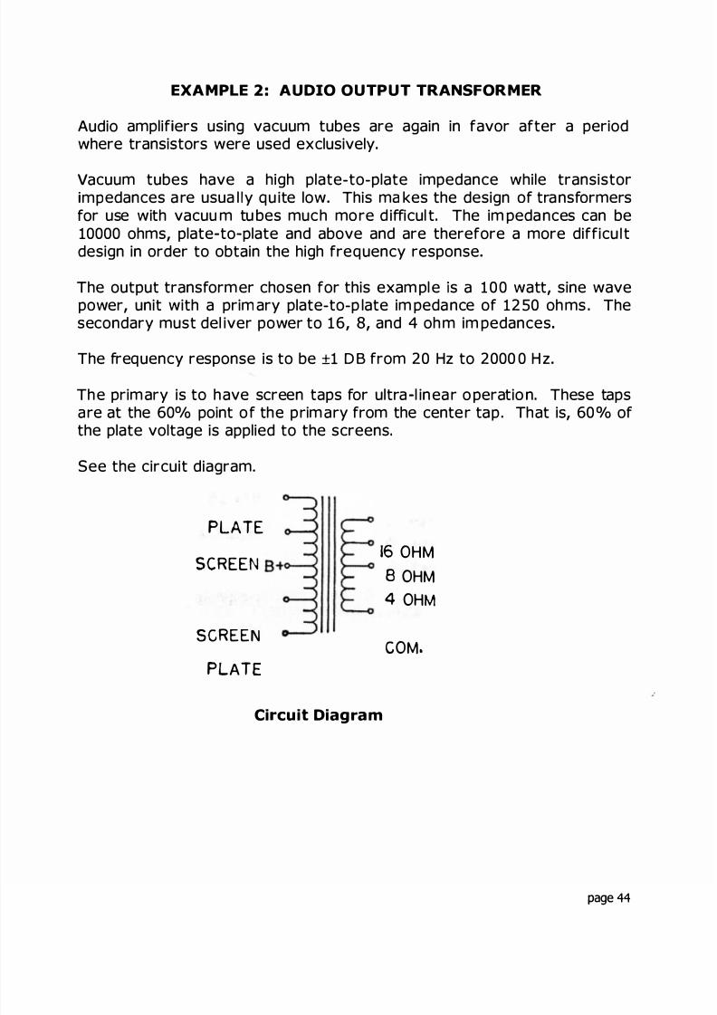
EXAMPLE 2: AUDIO OUTPUT TRANSFORMER
Audio amplif ers using vacuum tubes are again in favor after a periodwhere transistors were used exclusively.
Va cuum tubes have a high plate-to-plate impedance while transistormpedances a re usua l y qu ite low This ma kes the design of transformers
fo r use with vacuu m tu bes much more d ifficul t. The im peda nces can be10000 ohms, plate to plate and above and are therefore a more difficu tdesign in order to obtain the high frequency response
The output transformer chosen for this exam pl e s a 100 watt, sine wavepower, unit with a prim ary plate-to-p late im pedance of 1250 oh ms . Thesecondary must del iver power to 16, 8, and 4 oh m im pedances
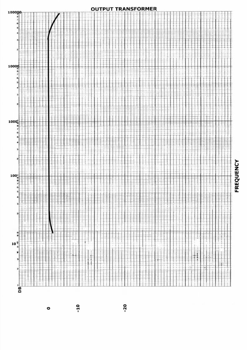
The frequency response is to be ±1 DB from 20 Hz to 2000 0 H z
The prim ary is to have screen taps for ultra l inea r o peratio n. These tapsare at the 60°/ point of the prim ary from the cente r tap . That is, 60 °/ ofthe plate voltage is applied to the screens.
See the circuit diagram
PLATE
SCREEN
R
P T
16 OHM
8 OHM
4 OH
COM.
Ci cuit Diagram
page 44
8/17/2019 Audio Transformer Design Manual - Robert G. Wolpert (2004)
http://slidepdf.com/reader/full/audio-transformer-design-manual-robert-g-wolpert-2004 47/117
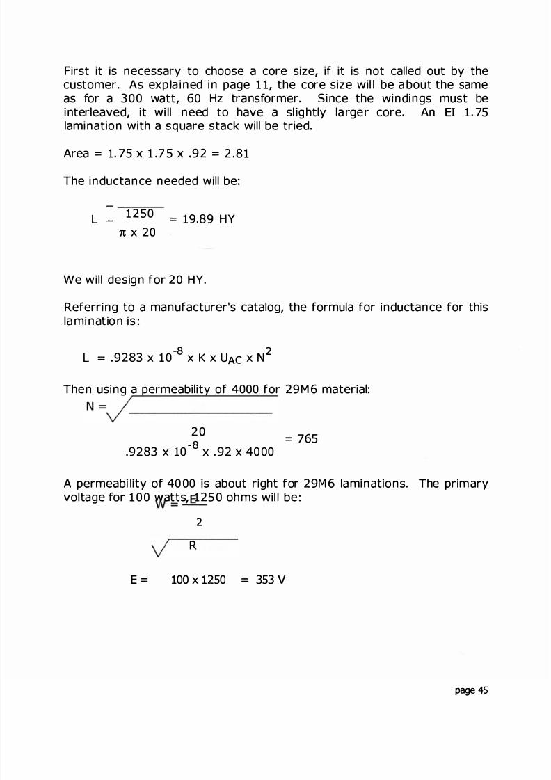
First it is necessary to choose a core size, if it is not called out by thecustomer As exp a ined in page 1 1, the core size wil l be a bout the sameas for a 3 00 watt, 60 z transformer. Since the windings must beinterleaved, it wi ll need to have a sl ightly la rge r core An EI 1 75lamination with a square stack will be tried
Area 1. 75 x 1 7 5 x 92 2 .81
The inductance needed will be
L - 1250 = 19.89 HY x 20
We will design for 20 HY.
Refer ing to a manufacturer's catalog, the formula for inductance for thisla mination is :
-8 2L = 9283 x 10 x K x U x N
Then using a permeability of 4000 for 29M6 material:
20-8
9283 x 10 x . 92 x 40 00765
A permeabi lity of 40 00 is about right for 29M6 laminations. The primaryvoltage for 1 0 0 watts, 125 0 oh ms wil be :
2= E_
R
E 100 x 12 0 3 3 V
page 45

8/17/2019 Audio Transformer Design Manual - Robert G. Wolpert (2004)
http://slidepdf.com/reader/full/audio-transformer-design-manual-robert-g-wolpert-2004 48/117
The turns for a m axi m um f lux density of 1 7 KG at 20 Hz wi ll be :
N =353 x 10
= 1290 T4.44 x 2 8 1 x 20 x 17000 x 6 45
1300 turns wil be used
In this case the turns needed for the inductance are less than thosenecessary for the flux density so the 1300 turns will have to be used
The B+ vo tag e wil l be appl ied to the center of the winding 60° of thevo tage will be at 1300 / 2 = 650 x 60 = 390 turns from the center tapThis wil l be 650 - 39 0 = 260 turns from the p late end of th e windings.
Secondary voltages wil be
16 OH M E = v 10 0 x 16 40 V
8 OHM E = 100 x 8 28 28 V
4 OHM E v 100 x 4 20 V
The secondary turns will be:
1300
353x 1 0 5 x 40 = 15 5 T
x 28 28 = 1 10 T
x 20 = 78 T
The 1 05 factor is to com pensate for the osses.
page 46
8/17/2019 Audio Transformer Design Manual - Robert G. Wolpert (2004)
http://slidepdf.com/reader/full/audio-transformer-design-manual-robert-g-wolpert-2004 49/117
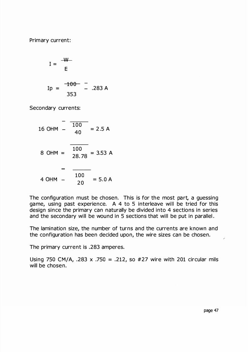
Primary current :
I = wE
Ip =1 0 0
353- .283 A
Secondary currents
16 OHM -
8 OHM =
4 O HM -
1 0 040
100
= 2 .5 A
28. 78 = 3 53 A
100
20
= 5. 0 A
The config uration must be chosen. This is for th e most pa rt, a guessingga me, using past experience. A 4 to 5 interleave wi l l be t ied for thisdesign since the primary can natu ally be divided into 4 sections in seriesand the secondary wi ll be wound in 5 sections that wi l be put in paral lel .
The lamination size, the number of turns and the currents a e known andthe configuration has been decided upon, the wire sizes can be chosen
The primary current is 283 amperes
Using 750 CM/A, 283 x .750 = 212, so #27 wire with 201 circular milswill be chosen
page 47
8/17/2019 Audio Transformer Design Manual - Robert G. Wolpert (2004)
http://slidepdf.com/reader/full/audio-transformer-design-manual-robert-g-wolpert-2004 50/117
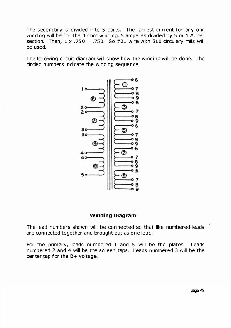
The secondary is d ivided into 5 parts The l argest cu rrent for any onew nding wi l be for the 4 ohm winding, 5 amperes d vided by 5 or 1 A persection Then, 1 x . 75 0 = . 75 0 So #21 wire with 81 0 circul ary m ls wilbe used
The fo l owing circuit diagr am wi ll s how how the wind ing wi l l be done. Thecircled numbers indicate the winding sequence
W nding D agram
The lead numbers shown wil be connected so that l ke numbered leadsare connected together and brough t out as one lea d
For the prim ary leads num bered 1 and 5 wi ll be the plates Leadsnumbered 2 and 4 will be the screen taps. Leads numbered 3 wi l be thecenter tap for the B+ voltage.
page 48

8/17/2019 Audio Transformer Design Manual - Robert G. Wolpert (2004)
http://slidepdf.com/reader/full/audio-transformer-design-manual-robert-g-wolpert-2004 51/117
For the secondary, leads numbered 6 will be for the 16 ohm winding.Leads nu mbered 7 wil l be for the 8 oh m winding Lead s nu mbered 8 willbe for the 4 ohm winding and the number 9 leads will be the commonpoint lead
The fil l can now be calcu lated The window for the EI 1 75 lamination is7/8" wide by 2 5/8" long The coi l length wi l be 1/16" less than thewindow length or 2 9/16 "
Using the methods shown in the exam ple in Section 5 . 3 :
The fill wil be calculated using the winding o der as shown in the circuitdiagram on page 48
page 49
8/17/2019 Audio Transformer Design Manual - Robert G. Wolpert (2004)
http://slidepdf.com/reader/full/audio-transformer-design-manual-robert-g-wolpert-2004 52/117
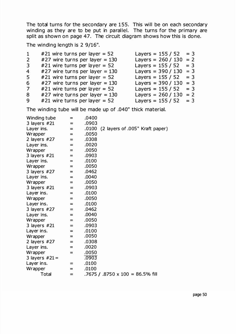
The total tu rns for the secondary are 1 55. This wi l l be on each secondarywinding as they are to be put in pa ral le l The turns for the pri ma ry arespl it as shown on page 47 . The circuit diag ram sh ows how this is done.
The winding length is 2 9/16".
1 #21 wire turns per layer = 52 Layers = 155 / 52 = 32 #27 wire turns per ayer = 130 Layers = 260 / 13 0 = 23 #21 wi re turns per layer = 52 Layers = 155 / 52 = 34 #27 wire turns per laye = 130 Layers = 3 90 / 1 30 35 #21 wire turns per laye 52 Layer s = 1 55 / 52 = 36 #27 wire turns per laye = 130 Layers = 390 / 13 0 = 37 #21 wi re turns per layer = 52 Layer s = 155 / 52 = 38 #27 wire turns per layer = 130 Layers 260 / 130 = 29 #21 wire turns per layer = 52 Layers = 155 / 52 = 3
The winding tube will be made up of .040" thick materia .
Winding tube = .04003 layers #21 .0903Layer ins. .0100 (2 layers o .005" Kra paper)Wrapper .00502 layers #27 .0308Layer ins. .0020Wrapper = .00503 ayers #21 = .0903Layer ns. .0100Wrapper = .00503 ayers #27 = .0462Layer ns. .0040Wrapper = .00503 layers #21 .0903Layer ins . .0100Wrapper = .0050Layer ins . .01003 ayers #27 .0462Layer ns. .0040Wrapper .00503 ayers #21 .0903Layer in s. .0100Wrapper .00502 layers #27 .0308Layer ins = .0020Wrapper .00503 layers #21 .0903Layer in s. .0100Wrapper = .0100
Total . 7675 I .875 0 x 100 86. 5°/ fi ll
page 50
8/17/2019 Audio Transformer Design Manual - Robert G. Wolpert (2004)
http://slidepdf.com/reader/full/audio-transformer-design-manual-robert-g-wolpert-2004 53/117
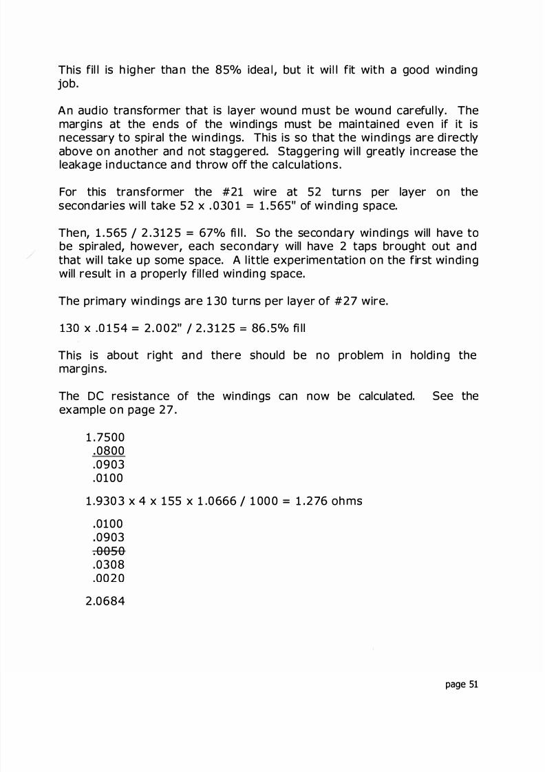
This fil l is h ig her than the 85° idea l , but it wi l fit with a good windingjob
An aud io transformer that is layer wound m ust be wound careful ly. Themargins at the ends of the windings must be maintained even if it isnecessary to spiral the windings. This is so that the windings are di rectlyabove on another and not stag gered Staggering wi ll greatly increase theleakage ind uctance and th row off the ca lcu lations .
For this transformer the #21 wire at 52 turns per layer on thesecondaries wi ll take 52 x . 0 30 1 = 1 565" of winding space.
Then 1 565 / 2 . 312 5 = 67° fi l l . So the seconda ry windings will have tobe spiraled, however each secondary will have 2 taps brought out andthat wil l ta ke up some space. A l ittle experimentation on the first windingwill result in a properly fil ed winding space
The prima ry windings are 1 30 tu ns per laye of #27 wire.
130 x .0 1 54 = 2 0 02" I 2 3 125 = 86 . 5° fi ll
Thi� is about right and the e should be no problem in holding themargins.
The DC resistance of the windings can now be calculated See theexample on page 27
1 .75000800
.0903
.0100
1 .930 3 x 4 x 1 55 x 1 .0666 / 1 00 0 = 1 276 oh ms
0100
09030050.0308.0020
2.0684
page 51
8/17/2019 Audio Transformer Design Manual - Robert G. Wolpert (2004)
http://slidepdf.com/reader/full/audio-transformer-design-manual-robert-g-wolpert-2004 54/117
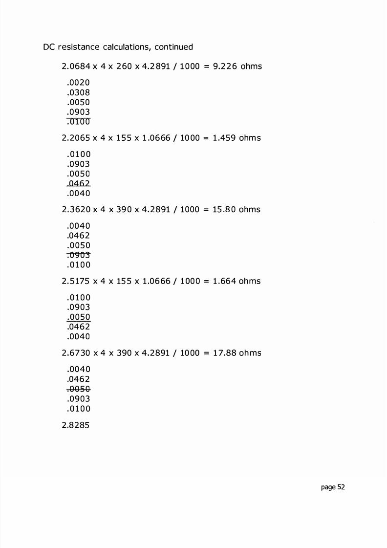
DC resistance calculations, continued
2 0684 x 4 x 260 x 4 2 891 / 1 0 00 = 9 226 ohms
0020
0308005009030 1 0 0
2 2065 x 4 x 1 5 5 x 1 .0666 I 10 00 = 1 459 ohm s
0 1 0 009030 0 5 0
.0462
.0040
2 3620 x 4 x 39 0 x 4 2891 / 1000 = 15 .8 0 ohms
.004004620 0 5 00903
. 0 1 0 0
2 5 175 x 4 x 15 5 x 1 .0666 / 1 00 0 = 1 .664 oh ms
0 1 0 0.0903
005004620040
2 67 30 x 4 x 390 x 4 2891 / 10 00 = 1 7 88 oh ms
0040
04620 0 5 0.0903. 0 1 0 0
2 8285
page 52

8/17/2019 Audio Transformer Design Manual - Robert G. Wolpert (2004)
http://slidepdf.com/reader/full/audio-transformer-design-manual-robert-g-wolpert-2004 55/117
DC resistance calculations, continued
2.8285 x 4 x 1 5 5 x 1 .0666 10 00 = 1 87 ohm s
. 0 1 0 009030 0 5 003080020
2.9666 x 4 x 260 x 4 2891 1000 = 13 .23 ohms
.0020
.0308
.0050
.0903
. 0 1 0 03.1047 x 4 x 155 x 1 0666 / 1000 = 2 053 ohms
The total primary resistance is:
9 226 + 15.80 + 17 88 + 13 23 = 56. 13 ohms
The voltage drop in the prima y is 56 14 x .2 83 = 1 5 88 V.
The seconda ies a re a ll in paral lel so that the su m of the windings will be
1Rs = = .32 3 OHMS
1 1 1 1 11 .276 1 459 1 .664 1. 87 2 0 53
This will be for th e 16 o hm winding
Calcul ate the output voltage :
(353 15 .88) 1300 x 155 = 40 .195 - .809 = 39.38 v
In order to increase the output to the desi ed 40 volts, the secondaryturns shoul d be increased to 1 57 Then the output wi ll be 39 9 V
page 53
8/17/2019 Audio Transformer Design Manual - Robert G. Wolpert (2004)
http://slidepdf.com/reader/full/audio-transformer-design-manual-robert-g-wolpert-2004 56/117
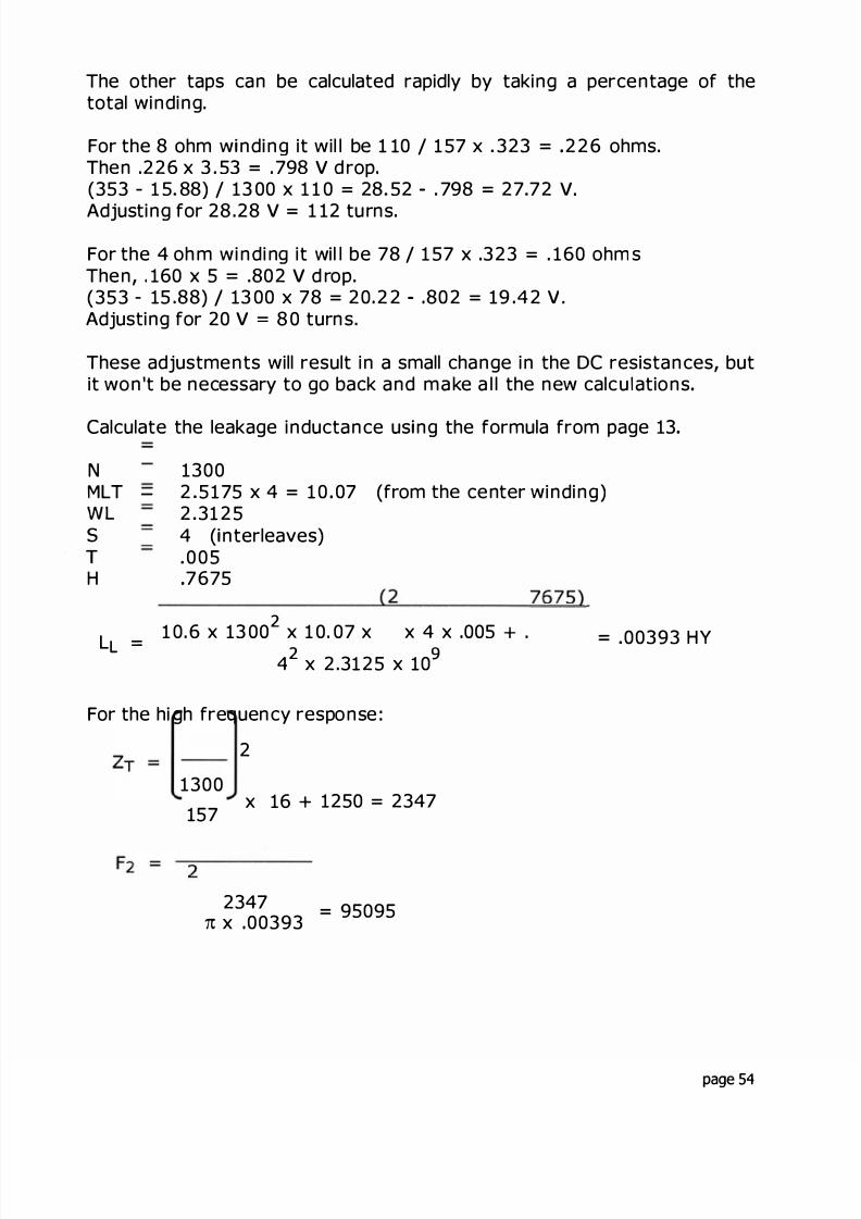
The other taps can be calculated rapidly by taking a percentage of thetotal winding.
For the 8 ohm w nding it wil l be 1 10 I 1 57 x 323 = 226 ohms.Then .226 x 3 53 = 798 V d rop(353 1 5 88) / 13 00 x 1 1 0 = 28 52 . 798 = 27 72 v
Adjusting for 28 .28 V = 1 12 tu rns
For the 4 oh m winding it wil l be 78 / 1 57 x 323 = . 160 ohm sThen, 160 x 5 = .802 V d rop.(353 - 15 .88) I 13 00 x 78 = 20 22 802 = 19 42 v .
Adjusting for 20 V = 8 0 turns.
These adjustments will result in a small change in the DC resistances, butit won't be necessary to go back and make a l l the new calcu ations
Calculate the leakage inductance us ng the formula from page 13
NMLT -
WLsT
H
13002 5175 x 4 = 10 07 (from the center winding)2 31254 ( nterleaves)
0 057675
L = 1 0.6 x 13 00 x 1 0. 07 x ( x 4 x 005 + .7675) = 00393 HY4 x 2.3125 x 10
For the hi gh frequency response :
2
1300
157x 16 + 1250 = 2347
23477 x 00393 = 95095
page 54

8/17/2019 Audio Transformer Design Manual - Robert G. Wolpert (2004)
http://slidepdf.com/reader/full/audio-transformer-design-manual-robert-g-wolpert-2004 57/117
8/17/2019 Audio Transformer Design Manual - Robert G. Wolpert (2004)
http://slidepdf.com/reader/full/audio-transformer-design-manual-robert-g-wolpert-2004 58/117
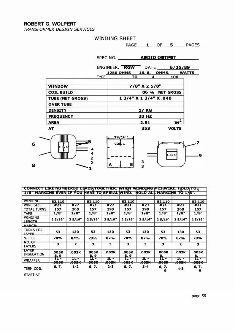
ROBERT G. WOLPERTTRANSFORMER DES GN SERVICES
WINDOWCOIL BUILDTUBE (NET GROSS)OVER TUBEDENSITY
FREQUENCYAREAAT
6 _ s 4
2
8 -2
1
WINDING SH EET
PAG E _ �- OF = _ PAG ES
SPEC N O
ENGINEER. RGW DATE �
TPE 1250 OHMS TO 16 8 4 OH 100 WATTS
7 x 56 /o NET GROSS
3 x 3 x
r29/16'�COIL 1
- - - - -
- - - - -
B
7 KG
HZIN
353 VOLTS
1 - 1
�4 33
7
CONNECT LIKE NU MB ERED LEADS TOGETHER; WHEN WINDING # 2 WIRE, HOLD TO/8 " MARGINS EVEN IF YOU HAVE TO SPIRAL WIND HOLD ALL MARGINS TO /8 "
WIND NG 2 3 4 5 6 7 8 9WIRE SIZE #21 #27#21 #27 #21 #27#21 #27 #21 TOTAL TU RNS 157 260 157 390 157 390 157 260 157 TAPS 82,110 82,110 82 110 82 110 82 110WINDING
2 5/16" 2 5/16" 2 5/16" 2 5/16 " 2 5/16" 2 5/16" 2 5/16" 2 5/16 2 5/16"LENGTHMARG N 1/8 1/8 1/8 1/8 1/ 8 1/ 8 1/8 1/8 1/8 T RN S E R
53 130 53 1305 3 130 53 130 5 3YER% F L 70 87° o 70° o87% 70% 87° o 70° o87 70%N O. OF
3 2 3 3 3 3 3 2 3YERSYER
.005K 002K.005K 002K005K002K 005K .002K INSU T ON
WRAPPER l - l - l - l - l - l - l - l l
.005K 005K 005K .005K 005K005K 005K .005K.005K TE RM CO 6,7, 1-2 6 , 7 , 2-3 6 , 7 , 3 - 4 6,7, 4-5
6 , 7 , 8 9 8 9 8 9 8 9 8 9STAR AT
page 56

8/17/2019 Audio Transformer Design Manual - Robert G. Wolpert (2004)
http://slidepdf.com/reader/full/audio-transformer-design-manual-robert-g-wolpert-2004 59/117
ROBERT G. WOLPERTTRANSFORMER DESIGN SERVICES
MATERIAL SH EET
PAR NO.
CORE EI- 1 3 429M6
COPPER#21 MAGNET WIRE
#27 MAGNET WIRE
CAN
LID-
LID B
ERM NALS
UBE 1 3/4" x 1 3 /4 x .040x 2 9/16 LONG
TERM BOARD
LUG PANEL
BK 1 3/4 HORIZ. "L"
BOL S #10 x 2"NU S #10
WASHERS #1 0 STEEL
WASHERS #10 FIBERLEADS #20 SLW x 10" ONG
#1 BLACK#2 BROWN#3 RED# 4 YELLOW#5 GREEN#6 BLUE#7 ORANGE#8 WHITE#9 VIOLET
NO ES:
PAGE 2 O F PAGES
SPEC NO. ___ A�U D= O. O " . PU � -
AMO
TO PRICE O PRICEPR CE
8 7#
1.63#0.68#
1
44484
111111111
pa ge 57

8/17/2019 Audio Transformer Design Manual - Robert G. Wolpert (2004)
http://slidepdf.com/reader/full/audio-transformer-design-manual-robert-g-wolpert-2004 60/117
ROBERT G. WOLPERTTRANSFORMER DESIGN SERVICES
F NISH NG
LEADS S ZECOLOR
#20 SLW BLACK
#20 SLW BROWN
#20 SLW RED
#20 SLW YELLOW
#20 SLW GREEN
#20 SLW BLUE
#20 SLW ORANGE
#20 SLW WHITE
#20 SLW VIOLET
LUGS OR LUG PANE :
PAR # EAD#
SPECIAL N S RUC IO NS :
PAGE 3 OF - PAGES
SPEC NO.
A U D=I 0 ; . - _
LENGTH OU LEAD#OF COIL
8 " 1
8" 2
8 " 3
8 " 4
8" 5
8" 6
8" 7
8" 8
8" 9
FINISH ALL LIKE NUMBERED LEADS TOGETHER.
page 58
8/17/2019 Audio Transformer Design Manual - Robert G. Wolpert (2004)
http://slidepdf.com/reader/full/audio-transformer-design-manual-robert-g-wolpert-2004 61/117
ROBERT G. WOLPERTTRANSFORMER DESIGN SERVICES
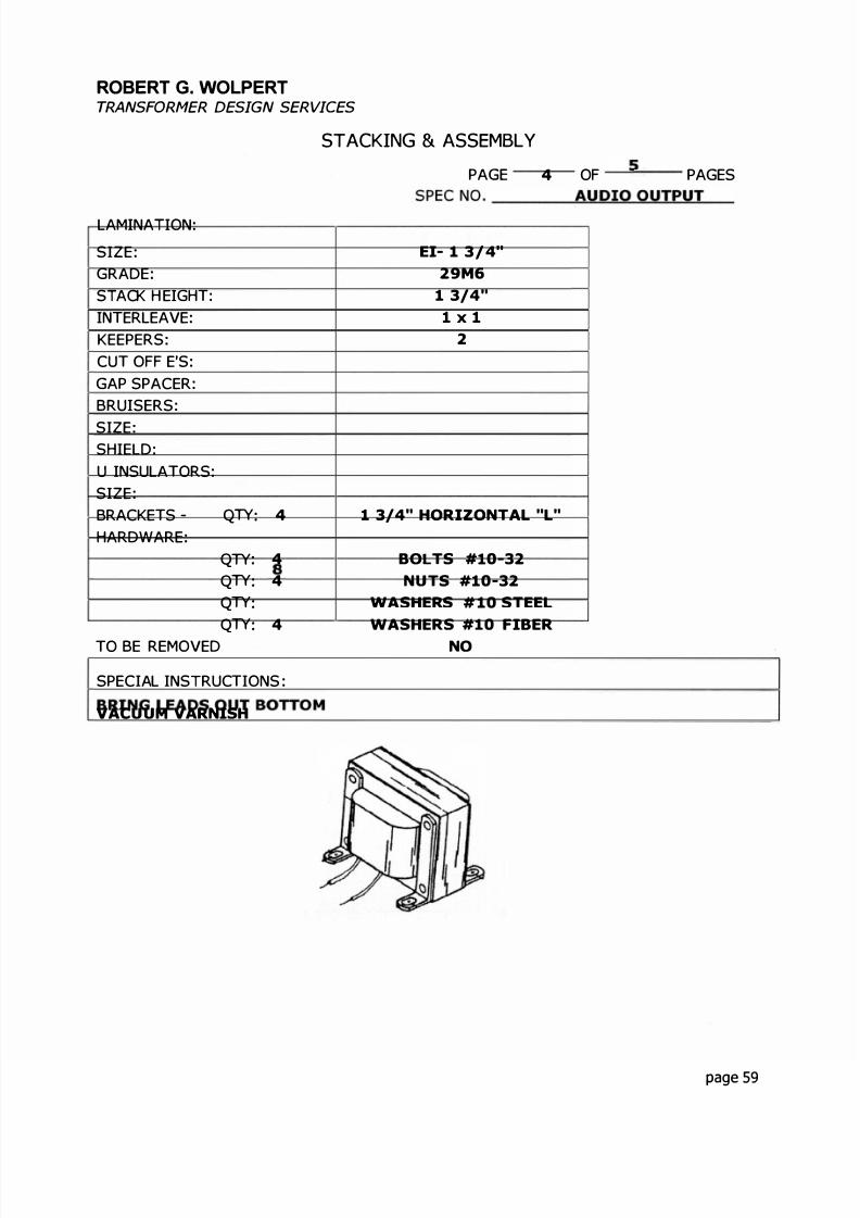
STACKING & ASSEMBLY
LAMINA ION:
SIZE:GRADE:S ACK H EIGH :IN ERLEAVE:KEEPERS:CU OFF E'S:GAP SPACER:BRUISERS:
SIZE:SHIELD:U INSULA ORS:SIZE:BRACKE S - Q 4HARDWARE:
Q 4
Q 4
Q 8
Q 4O BE REMOVED
SPECIAL INSTRUC IONS:
VACUUM VARNISH
PAGE 4 OF _ PAGES
SPEC NO__
_ A U "D " . _
EI- 1 3 /4"29M6
1 3/4"l x l
2
1 3/4" HORIZON AL "L"
BO S # 0-32NU S #10-32
WASHERS # 10 STEELWASHERS #10 FIBER
NO
page 59

8/17/2019 Audio Transformer Design Manual - Robert G. Wolpert (2004)
http://slidepdf.com/reader/full/audio-transformer-design-manual-robert-g-wolpert-2004 62/117
ROBERT G. WOLPERTTRANSFORMER DESIGN SERVICES
TEST INSTRUCTIONS
PAGE 5 O F _ PAGES
SPEC NO -
PROCEDURE
1ST TEST2ND TEST3RD TESTFINAL TEST (AFTER VARNISH)
1 NO OAD VO TAGE RAT O
APPLY v HZ TO TERM
READ V TE R M
V TE R M
V TE RM
2 ND UCTANCE TEST
APPLY v HZ TO TERM
READ "L M N
3 N DUCED VOLTAG E TEST
APP Y v HZ TO TERM
4. MUST MEG MEGOHMS MIN
5 H POT
EAD NO. TO6
1 6 CORE
CASE
6 CONT NU TY
7 SPEC AL TESTS :
s = 5 ohm= 6 ohm
e i made acro the ent re econda ye re ult on the fo ow ng page
67
-
s, 6
lex MAX.
& A D C
OR SEC
VO TS D C.
VO TS000
000
page 60
8/17/2019 Audio Transformer Design Manual - Robert G. Wolpert (2004)
http://slidepdf.com/reader/full/audio-transformer-design-manual-robert-g-wolpert-2004 63/117
· 4 - 2 .
t I. •
·
1 � -
10 9 _ r :
f 1
7 ;_. � J ..-=·
" - -
0
. -
_ C -
+
+ f
a - - r 1 T
! �. t
0' I
"! ' . �
!. !
. - ·+ - t
- i - - -
, _ _ _ .
0N
_ J
· - 1 . _· .L
- · r · . • .
I.
f -
> � - · 1 i
:; ' : : ..� � �
. t ... -· .. ·= = .. . ..
. .�:-�. :; : =�· --
>uzw
OwaI

8/17/2019 Audio Transformer Design Manual - Robert G. Wolpert (2004)
http://slidepdf.com/reader/full/audio-transformer-design-manual-robert-g-wolpert-2004 64/117
EXAMPLE 3: LINE-TO-VOICE COIL TRANSFORMER
Line to voice coil transformers are widely used in the transmission ofmusic and for pub ic ad dress systems. A design for th is type transformeris one of the most difficult to obtain The fol lowing exam p e wil l sh ow the
design of a typical line-to voice coi transformer.
The requ iremen ts for this un it are:
70 . 7 volt lin e to 4, 8 a nd 16 ohm s output with power ratings of 8, 16 a nd32 watts. The frequency response is ± DB from 30 z to 15000 z.Insertion loss of 0 5 D B maxim um .
- 6
l 8 OHMS
Circu t D agram
Connections to the appropriate leads will give the desired wattage andoutput impedance
Since this unit wil be about 3 DB down at 15 z ( 1 DB at 30 z), it willrequire a lamination that can support about 32 watts x 4 = 128 VA at 60Hz.
By divid ing 60 z by 15 z, a factor of 4 i s obtained for powerrequirements of the lamination for this transformer.
From the Lamination Tab e in the Appendix, El- 1 1/4" x 1 1/4" is goodfor 90 VAA 1 1/2" stack of this size amination shou d be about right as a startingpoint for 128 VA.
page 62

8/17/2019 Audio Transformer Design Manual - Robert G. Wolpert (2004)
http://slidepdf.com/reader/full/audio-transformer-design-manual-robert-g-wolpert-2004 65/117
8/17/2019 Audio Transformer Design Manual - Robert G. Wolpert (2004)
http://slidepdf.com/reader/full/audio-transformer-design-manual-robert-g-wolpert-2004 66/117

8/17/2019 Audio Transformer Design Manual - Robert G. Wolpert (2004)
http://slidepdf.com/reader/full/audio-transformer-design-manual-robert-g-wolpert-2004 67/117
he configuration as shown later will result in a change of turns in boththe prima ry an d secondary.
The configuration must now be considered. t is advisable to split theprima ry so that a 2 : 1 interleave is achi eved . By splitting the primary in
the center of the low impedance winding (32 watts) and adjusting thewinding configu ration of the p rim ary and seconda ry the mi ni mu m voltagegradient can be obtai ned .
If the 31 8 turns ca n be sp lit into 15 9 + 1 59 an d then pu t the 4 wattwind ing in between The 4 watt wi nd in g is 52 turn s
his is spl it into 26 + 2 6.
So we now have 159 T primary 26 T secondary 26 secon dary ; 159 primary
We need 318 turns more on the primary and 52 more turns on thesecondary In o rde r to preserve the voltage gradie nts an d split thewindings evenly, the additional primary turns should be divided andadded at each en d. he addition al secon dary tu rns sh ou ld be put in thecenter of the secondary.
hen the win din g configu ration wil l be
1 59 + 15 9 ; 26 T + 2 6 + 26 + 2 6 ; 1 59 + 1 59 T
his will give the total primary turns and secondary turns. t rema ins tonumber these windings so they will be connected properly.
159 + 159; 26 + 26 + 26 + 26 ; 159 + 159
2 -3 3-A 7-B 5 - 6 6 -7 B-8 A 4 1 2
© 0
page 65

8/17/2019 Audio Transformer Design Manual - Robert G. Wolpert (2004)
http://slidepdf.com/reader/full/audio-transformer-design-manual-robert-g-wolpert-2004 68/117
This circuit diag ra m wi show how the win din gs are interleaved Thecirc ed numbers in the diagram show the order in which the windings willbe wound .
Circuit Diagram
The primary will be
3-A, A-4 = 3 1 8 turns for 3 2 watts
2-3-A-4 = 477 turns for 1 6 watts
2 3 A 4= 636 turns for 8 watts
Since 2 3 3 A are together they can be wound as one winding of 3 8turns tapped at 59 turns an d not be separate windin gs.
The secondary will be:
5 6 + 6 7 +7 B + B 8 = 04 turns for 6 ohms
6 7 + 7 B + B-8 = 78 tu rns for 8 ohms
7 B + B 8 = 5 2 turns for 4 ohms
This will result in the correct turns for the 8 watt and 3 2 watt windings,but the 6 watt will be 477 turns This is a deviation of 6°/o which isacceptab e . Also, the second ary turns have al so been adjusted and willresult in a deviation for the 8 ohm w ind ing of a pproxi mately 6 /o .
page 66
8/17/2019 Audio Transformer Design Manual - Robert G. Wolpert (2004)
http://slidepdf.com/reader/full/audio-transformer-design-manual-robert-g-wolpert-2004 69/117
The next step is to determine the wire sizes and cal cul ate the fil l .
The highest current in the primary wil be in the 32 watt winding.
w 32 = .452A 32 WI =
-0E
1 6 = 226A 1 6 w0
8 = . 1 13A 8 W0
he highest current in the secondary winding w ll be the 4 ohm w ndingand at 32 watts.
I = � = 2 .82 A 4 H M
= 2.0 A B OH M
= 1 41 A 16 OHM
#26 AWG wi e will be 254 / 452 = 562 CM/A for the primary.
#1 6 AWG wire will be 1 624 / 2.82 = 575 CM/A for the seconda ry.
These sizes are smaller than suggested previously, but will be su icient,as they are worst case for 32 watts and 4 ohms.
page 67

8/17/2019 Audio Transformer Design Manual - Robert G. Wolpert (2004)
http://slidepdf.com/reader/full/audio-transformer-design-manual-robert-g-wolpert-2004 70/117
CALCULATE THE FILL
The window for th s size la mination is 5/8" x 1 7 /8" The coil lengthshould be 1/32" shorter than the window
Coil length 1 27/32"#26 winding length 1 19/32", the ma rgins will be 1/8" each endTurns per layer 80 (from the Wire Table in the Appendix)Layers 31 8 80 4
# 16 winding length 1 19/32", the margins will be 1/8" each end.Turns per layer 26Layers 26 / 26 1
#16, 26 turns 1 layer# 16, 26 turns 1 layer#16, 26 turns 1 layer#26, 80 turns per ayer 159 80 2 layers#26, 80 turns per ayer 159 80 2 layers
The fi l can now be calcu lated using the configu ration on page 67
W nding tube .04004 L #26 w re .0684
Layer ins.=
.0090 (3 layers of .003 " K aft paper)Wrap .0100 K1 L #16 w re .0527Wrap .0100 K1 L #16 wire .0527Wrap .0100 K1 L #16 wire = .0527Wrap 0100 K2 L #26 w re .0342Laye ns .0060 KWrap .0100 K2 L #26 wire .0342Layer ins. = .0060 KWrap .0100 K
Tota .4265 I . 625 x 100 70°/ fi l
This fill is 0 K
page 68

8/17/2019 Audio Transformer Design Manual - Robert G. Wolpert (2004)
http://slidepdf.com/reader/full/audio-transformer-design-manual-robert-g-wolpert-2004 71/117
The w nd ng res stances can now be calculated (see page 26).
From the f ll figures and the lam nat on s ze:
The equ valent of a square tube w l be 1 25 + 1.5 2 75 / 2 1 375.
Core 1.3750.0800
06840900
1 5324 x 4 x 318 1000 x 3 4005 6.628 ohms
.009006840100
.0527
1.6725 x 4 x 26 1000 x 3346 = .0582 ohms
.0527
.0100
.0527
1 7609 x 4 x 26 1000 x .3346 .0612 ohms
.0527
.01000527
1.8763 x 4 x 26 1000 x 3346=
.0652 ohms.0527.0100.0527
1.9917 x 4 x 26 1000 x .3346 = .0693 ohms
.0527
.01000342
.0030
2.0916 x 4 x 159 1000 x 3.4008 4.523 ohms
.0030
.0342
.0100
.0342
.0030
2 1760 x 4 x 159 I 1000 x 3.4008 = 4. 706 ohms
page 69

8/17/2019 Audio Transformer Design Manual - Robert G. Wolpert (2004)
http://slidepdf.com/reader/full/audio-transformer-design-manual-robert-g-wolpert-2004 72/117
The mean length turn will be in the center of the windings which will be1 . 8763 x 4 7 5" . This will be used in calculating the leakageinductance
This winding configuration has all of the secondaries in between theprimaries, so a 2 to 1 interleave will be used.
From page 13, the formula for leakage inductance, using the values forthis transformer i s:
Where:
5
W
HMLT -N
2
10.6 x (636) x 7.5 x (2 x 2 x .010 + .4265)
2 x 1.593x 10
1 19/32010
.42657 5636 (the total prima ry turns)
= .00235
The high frequency response can be cal culated us ing this va lue of leakageinductance
Z 16 + 625 1223104
F1223 82895 HZ
2 7 x .00235
page 70

8/17/2019 Audio Transformer Design Manual - Robert G. Wolpert (2004)
http://slidepdf.com/reader/full/audio-transformer-design-manual-robert-g-wolpert-2004 73/117
It should be noted that this has been calculated using the entire primaryand second ary. Wh en taps are used for different wattages and outputs,the high frequency response will not be as good.
This is due to the windings that are not used causing the effective
leakage ind uctance to be d ifferent. Thi s is dif icu lt to ca cu late an d, whenthe upper end is beyond the requirements, it will not be attemptedHowever, it will be tested and the results put on the frequency responsegraph to show the difference.
he insertion loss requi rement is for 5 DB maxi mum From page 64,the total p rima ry turns are 636 . The total secon da ry tu rns are 04.
By adding the resistances, as calculated on page 69, the tota primaryresistance is 6.28 + 4 523 + 4 7 6 = 15 5 ohms
The total secondary resistance is:
582 + 612+ . 652 + 693 = 2539.
R = t R + R = t x04
ILR
X 00Z1
=25 x 00 =
625
254 + 1 5 . 5 = 25
4°
Referring to page 7 , this being ess than 0° , it wi ll meet the 5 DBmaximum
he insertion l oss will be d fferent for the different taps This makes itnecessary to cal cul ate what probab y is the worst case Thi s is for 32watts and 4 ohms as they are the windings that will carry the highestcurrent
page 71
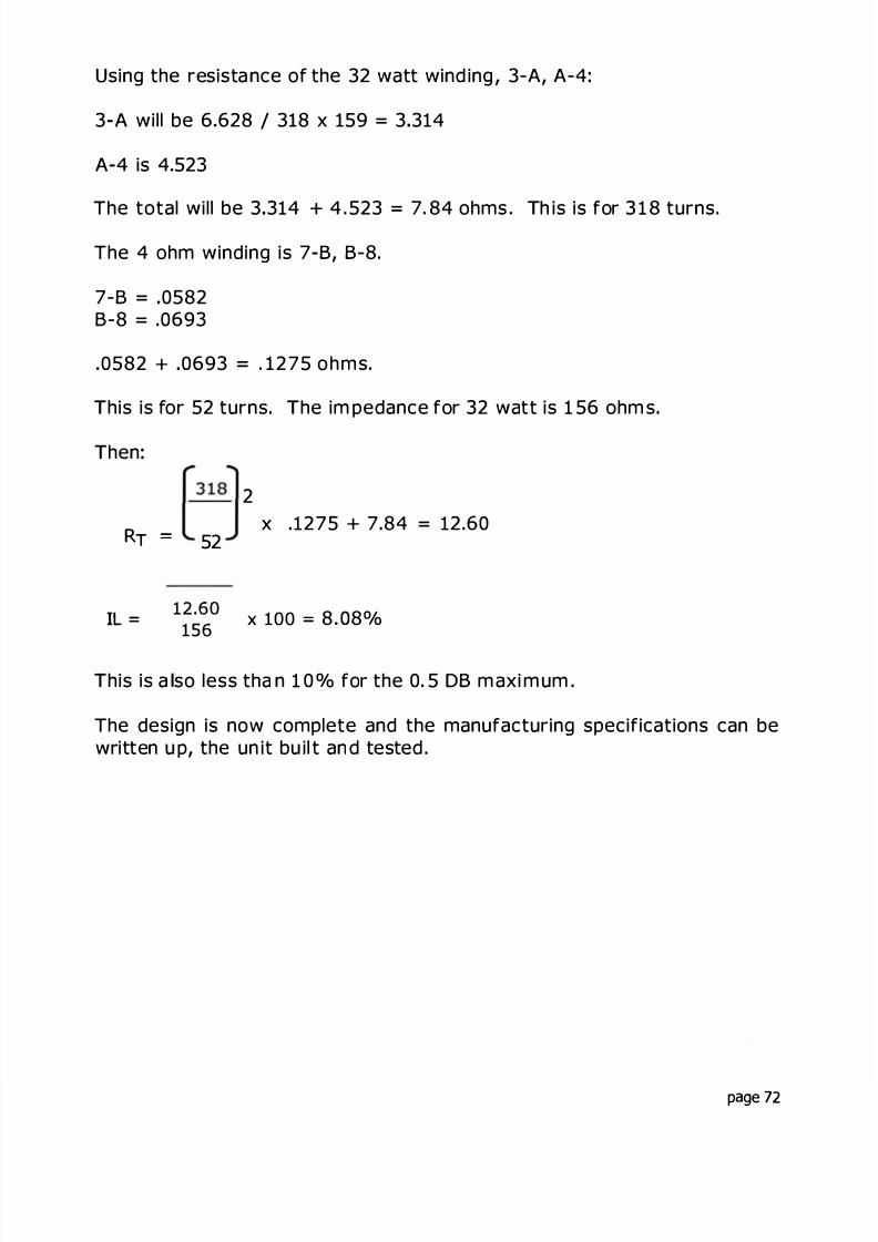
8/17/2019 Audio Transformer Design Manual - Robert G. Wolpert (2004)
http://slidepdf.com/reader/full/audio-transformer-design-manual-robert-g-wolpert-2004 74/117
Using the resista nce of the 32 watt wind ing , 3 A, A 4:
3-A will be 6 628 / 3 8 x 59 = 3 314
A-4 is 4 523
The total will be 3 314+
4 . 523 = 7. 84 ohms . h is is for 3 1 8 turns.The 4 ohm winding is 7-B, B 8.
7 B = 0582B 8 = .0693
0582 + 0693 . 275 ohms
his is for 52 turns. he im pedance for 32 watt is 1 56 ohm s
hen:
[ s ] 2x .1275 + 7.84 = 12.60
RT L52
IL =12 .60
156x 100 8 08°
his is a so less tha n 1 0 ° for the 0. 5 DB m axi m um .
The design is now complete and the manufacturing specifications can bewritten u p, the un it bu il t an d tested .
page 72
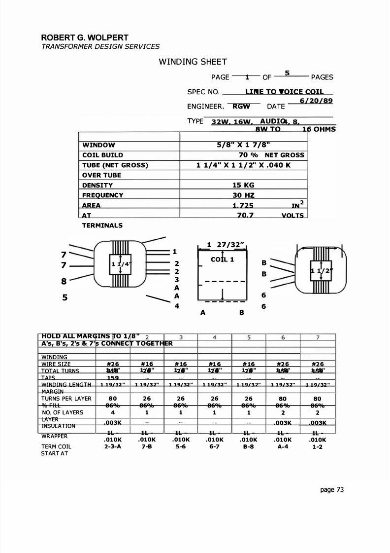
8/17/2019 Audio Transformer Design Manual - Robert G. Wolpert (2004)
http://slidepdf.com/reader/full/audio-transformer-design-manual-robert-g-wolpert-2004 75/117
ROBERT G. WOLP RTTRANSFORMER DESIGN SERVICES
WINDING SHEET
WINDOW
COIL BUILD
TUBE (NET GROSS)
OVER TUBE
DENSITY
FREQUENCYAREA
AT
TERMINALS
7 1
7 22
8 3
A
PAGE 1 OF -� _ PAGES
SPEC NO. -
ENGINEER RGW DATE 6/20/89
PE AUDIO32W. 16W W TO 4, 8 16 OHMS
5/8" x 1 7/8"70 /o NET GROSS
1 1/4" X 1 1 / 2" X 040 K
15 KG
30 HZ1 725 IN
70 7 VOL S
1 27/32 1 - 1rCOIL 1� B
B-
- - -
5 - A 6
4 6A B
HOLD ALL MARGINS TO 1/8 "A's, B s, 2's & 7 s CONNECT TOGETHER
W ND NG 2 3 4 5 6 7W RE SIZE #2 6 # 1 6 # 1 6 #1 6 # 1 6 #2 6 #2 6TOTA TURNS 3 1 8 2 6 2 6 6 2 6 159 159TAPS 159 - -
W ND NG ENGTH 1 19/ 2" 1 19/ 2" 1 19/ 2" 1 19/ 2" 1 19/ " 1 19/ 2" 1 19/ 2"MARG NTURNS ER YER 80 6 2 6 2 6 2 6 80 80% F L 86% 86° /o 86° /o 86% 86% 86° /o 86%NO. O AYERS 4 1 1 1 1 2 2
YER.003K 003K 003KNSULAT ON
WRAPPERl l l - l - 1L - l l - l -
OlOK OlOK OlOK .OlOK OlOK OlOK OlOKTERM COI 2 3 A 7-B 5-6 6 7 B 8 A 4 1 2START A
page 73
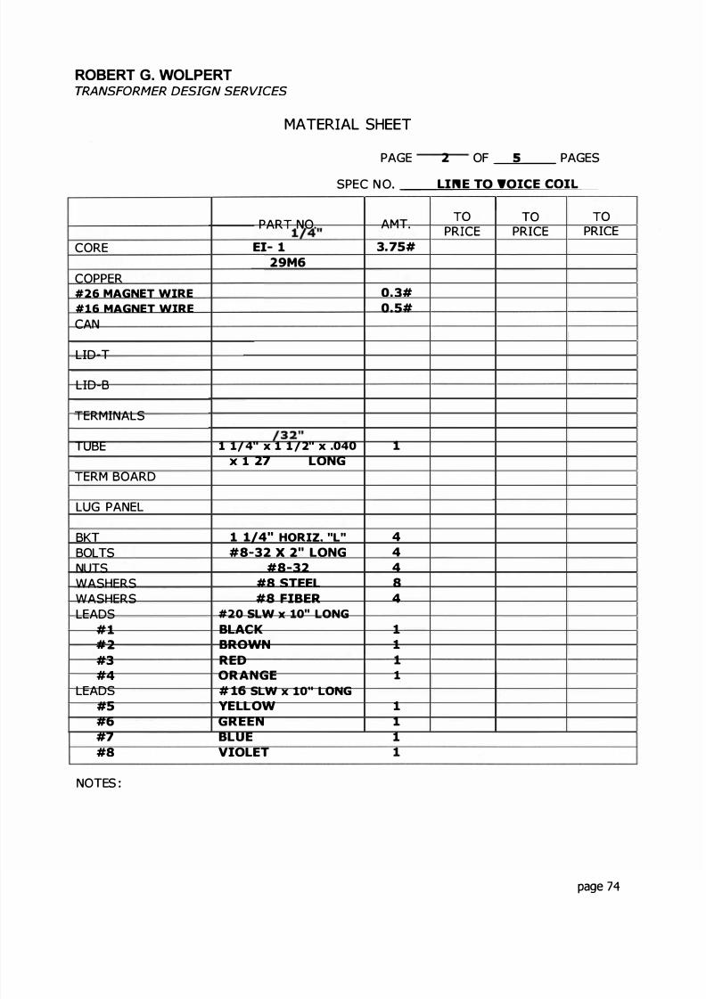
8/17/2019 Audio Transformer Design Manual - Robert G. Wolpert (2004)
http://slidepdf.com/reader/full/audio-transformer-design-manual-robert-g-wolpert-2004 76/117
ROBERT G. WOLPERTTRANSFORMER DESIGN SERVICES
CORE
COPPER#26 MAGNET WIRE
#16 MAGNET WIRE
CAN
L D-
L D B
TER NALS
UBE
TER BOARD
LUG PANE
BKBOL SNU SWASHERSWASHERSLEADS
#1#2#3# 4
LEADS# 5
#6#7#8
NO ES :
MATERIAL SHEET
2 OF _ PAGESPAGE
SPEC N O. �
PART NO AMTO O TO
PRICE PR CE PR CEEI- 1 1/4 3.75#
29M6
0.3#0.5#
1 1/ 4" x 1 1 /2" x 040 1x 1 27 32 LONG
1 1/4" HORIZ. "L" 4#8 32 X 2" LONG 4
#8-32 4#8 STEEL 8#8 FIBER 4
#20 SLW 10 LONG
BLACK 1BROWN 1RED 1ORANGE 1# 16 SLW x 10" LONG
YELLOW 1GREEN 1BLUE 1VIOLET 1
page 74

8/17/2019 Audio Transformer Design Manual - Robert G. Wolpert (2004)
http://slidepdf.com/reader/full/audio-transformer-design-manual-robert-g-wolpert-2004 77/117
ROBERT G. WOLPERTTRANSFORMER DESIGN SERVICES
FINISHING
LEADS SIZE COLOR
#20 SLW BLACK
#20 SLW BROWN
#20 SLW RED
#20 SLW ORANGE
#1 6 SLW YELLOW
#16 SLW GREEN
#16 SLW BLUE
# 1 6 SLW VIOLET
LUGS OR LUG PANEL
PAR # LEAD #
SPECIAL INSTRUC IONS:
3 OF - PAGESPAGE
SPEC N O. �
LENG H OU LEAD #OF COIL
8" 1
8" 2
8" 3
8" 4
5
6
7
8
CONNECT ALL LIKE NU MB ERED AN D LETTERED LEADS TOGETHER.
BLIND A's & B's
pa g e 7 5

8/17/2019 Audio Transformer Design Manual - Robert G. Wolpert (2004)
http://slidepdf.com/reader/full/audio-transformer-design-manual-robert-g-wolpert-2004 78/117
ROBERT G. WOLPERTTRANSFORMER DESIGN SERVICES
STACKING & ASSEMBLY
LAM NAT ON
S EGRADES ACK E G
N ERLEAVEKEEPERSCU OFF E'SGAP SPACERBRU SERS
S ES E D:U NSU A ORSS ZEBRACKE S - Q 4HARDWARE
Q 4Q 4Q 8Q 4
TO BE REMOVED
SPEC AL NS RUC ION S:
VACUU M VARNISH
PAGE 4 OF � PAGES
SPEC NO. _ I .N E- O O C=O
EI- 1 1/4"29M6
1 1/2"1 x 1
2
1 1/4" HORIZONTAL "L"
BOLTS 8 32 x 2NUTS 8 32
#8 WASHERS, STEEL#8 WAS ERS FIBE R
NO
page 76

8/17/2019 Audio Transformer Design Manual - Robert G. Wolpert (2004)
http://slidepdf.com/reader/full/audio-transformer-design-manual-robert-g-wolpert-2004 79/117
ROBERT G. WOLPERTTRANSFORMER DESIGN SERVICES
TEST INSTRUCTIONS
PAGE 5 OF = _ PAGES
SPEC NO _ � N. TO VO= O = �
PROCEDURE
1ST TEST2ND TES3RD TESFINA ES (AFTER VARNISH)
1. NO LOAD VOLTAGE RATIO
APPLY v HZ TO TERM
READ V TERMV TERM
V TERM
2 INDUCTANCE TEST
APPLY v HZ TO TERM.
READ "L MIN
3 INDUCED VO LTAGE TEST
APPLY4 MUST MEG
5 HIPOT
6 CONTINUITY
v
LEAD NO.
1 5
7 SPECIAL TESTS:
s = 625 ohms
L = 1 ohms
HZ TO TERM
MEGOHMS MIN
TO5
CORE
CASE
Test across the tota p imary and secondaryTest resu ts on t e fo ow ng page
67
--
6, 5
lex MAX
& A D C
FOR SEC
VOLTS D C.
VOL S500
500
ge 77

8/17/2019 Audio Transformer Design Manual - Robert G. Wolpert (2004)
http://slidepdf.com/reader/full/audio-transformer-design-manual-robert-g-wolpert-2004 80/117
3
_ . _.
I
aQ
_, }
0 0NI
· - t ._ - � 1 �
,_
i r
-._ r
-�t : -r -
•· · · 1 .
-.!- - �-·
· · _ I- . - r -
: f ;
t - t - 1 · ._ :t
- - ; r' -
+ +- r� -
l l ' :� .f I t
·•- � -1
>uzw:Owau

8/17/2019 Audio Transformer Design Manual - Robert G. Wolpert (2004)
http://slidepdf.com/reader/full/audio-transformer-design-manual-robert-g-wolpert-2004 81/117
APPENDIX
page 79
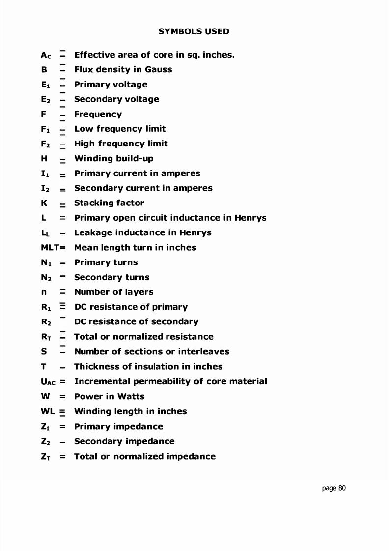
8/17/2019 Audio Transformer Design Manual - Robert G. Wolpert (2004)
http://slidepdf.com/reader/full/audio-transformer-design-manual-robert-g-wolpert-2004 82/117
SYMBOLS USED
A - Ef ect ve area of core n sq. nches.
B - Flux dens ty n Gauss
E Pr mary voltage
E2 - Secondary voltageF - Frequency
F Low frequency l m t
F2 - H gh frequency m t
H W nd ng bu ld-up
1 Pr mary current n amperes
12- Secondary current n amperes
K Stack ng factor
L Pr mary open c rcu t nductance n Henrys
L Leakage nductance n Henrys
ML = Mean ength turn n nches
N - Pr mary turns
N2 - Secondary turns
n - Number of ayersRi DC res stance of pr mary
R2 DC res stance of secondary
RT - otal or normal zed res stances Number of sect ons or nterleaves
h ckness of nsu at on n nches
U Ac = Incremental permeab l ty of core mater al
w - Power n Watts-
WL = W nd ng length n nches
Z Pr mary mpedance-
Z2 - Secondary mpedance
ZT - otal or normal zed mpedance
page 80

8/17/2019 Audio Transformer Design Manual - Robert G. Wolpert (2004)
http://slidepdf.com/reader/full/audio-transformer-design-manual-robert-g-wolpert-2004 83/117
DB EXPRESSED N WATS
DB MICRO-WATS DB WATS80 0 00001 0 0 0 0 0 17 0 0 0 0 0 1 1 0 0 . 0 0 1 3
-60 0 . 0 0 1 2 0 0 . 0 0 1 6-so 0 . 0 1 3 0 0 .002
40 0 . 1 4 0 0 . 0 0 2 S- 3 0 1 0 s . o 0 .0032- 2 0 1 0 . 0 6 0 0 004- 1 9 12 .26 7 0 o oos- 1 8 l S . 9 8 0 0.0063- 1 7 2 0 . 0 9 0 0.0079-16 2 S . 1 1 0 0 0 . 0 1
l s 3 1 . 6 1 1 . 0 0 . 0 1 2 614 3 9 . 8 1 2 . 0 0 .01S9
- 1 3 S 0 . 1 1 3 0 0 . 0 21 2 6 3 1 1 4 0 0 02S
- 1 1 79 .4 l S O 0 . 0 3 1 6- 1 0 1 0 0 . 0 16 0 0 .0398- 9 1 2 6 0 1 7 0 o oso- 8 1 5 9 0 1 8 0 0.063- 7 2 0 0 0 1 9 . 0 0.079- 6 2 S 1 0 2 0 . 0 0 . 1 0
s 3 1 6 0 3 0 0 1 . 0- 4 398 0 4 0 0 1 0 0- 3 S O l O s o . a 100 .0
2 6 3 1 . 0 6 0 . 0 1000 0- 1 794 0 7 0 . 0 10000 .0
0 1 0 0 0 . 0 8 0 . 0 100000 .0
page 81

8/17/2019 Audio Transformer Design Manual - Robert G. Wolpert (2004)
http://slidepdf.com/reader/full/audio-transformer-design-manual-robert-g-wolpert-2004 84/117
WIRE TABLE
SIZE OHMS/ IN SUL MARGINCM DIA TURNS/
O S/LB1000" AREA IN
42 139.00 .0007 1/16 6 25 0028 304.0 84648.0
41 110 .25 .0007 1/16 7.8 .0032 267.0 54045.040 87.42 .0007 1/16 9 9 .0036 239.0 35610.039 69.32 .0007 1/16 12 5 .0040 215 .0 22047.038 54 97 .001 1/16 1 5 . 7 .0045 192 3 12887.03 7 43.59 .001 3/32 19 8 .0051 170.4 8077.036 34.56 .001 3/32 25 0 0056 155 .5 5248.03 5 27.42 .001 3/32 3 1 5 2 0062 142.0 3375.034 21 74 .001 3/32 39.75 0070 125 .6 2106.03 3 17.24 .0015 3/32 5 0 1 3 0079 110.4 1305.032 13 67 .0015 3/32 63 2 .0089 99.0 810 0
3 1 10.84 .0015 3/32 79.7 .0099 88.9 530 030 8 60 .0015 3/32 100.5 . 0 11 0 8 1 0 333.42 9 6.82 0015 1/8 126.7 .0123 72.5 204.628 5.41 0015 1/8 159 8 0137 63 .0 132.527 4.29 .002 1/8 2 0 1 . 3 .0154 57.6 82 .526 3.40 .002 1/8 254.1 0171 52 0 52 725 2.70 .002 1/8 320.4 0192 45.9 32.724 2.14 002 1/8 404 0 0215 41.9 20 723 1.70 003 1/8 509 5 .0240 37.4 12.922 1.345 .003 1/8 642 4 0268 33 6 8 22
21 1.067 .003 1/8 8 1 0 1 0301 3 0 3 5 1 220 .8458 005 1/8 1022 0 0336 26.7 3 2319 6709 005 1/8 1288 0 .0376 24.3 2.0418 .5320 007 1/8 1624 0 .0421 21 7 1.2917 .4220 007 1/8 2045 0 0471 19 3 80516 .3346 010 1/4 2533 0 .0527 17.6 .510115 .2653 010 1/4 3257.0 .0590 1 5 . 9 .319314 .2104 .010 1/4 4107.0 0661 14.2 .201613 1669 .010 1/4 5778.0 0741 12.8 .125812 1 3 2 3 .010 1/4 6530.0 .0829 11 . 5 0794
11 .1050 010 1/4 8234 0 .0929 1 0 2 .050010 .0833 .010 1/4 10380 0 .1042 9 .5 03159 .0660 010 1/4 13090 0 1168 8.2 .01988 0524 010 1/4 16510 0 1310 7 2 .0125
page 82

8/17/2019 Audio Transformer Design Manual - Robert G. Wolpert (2004)
http://slidepdf.com/reader/full/audio-transformer-design-manual-robert-g-wolpert-2004 85/117
LAMINATION TABLE
SIZE STACK HT VA AREA WINDOW WEIGHTLBS .
EI-187 3/16 0 5 035 3/16 x 7/16 015EE-24 25 1/4 1 0 0625 1/4 x 1/2 034
EI-3/8 3/8 3 . 0 1406 5/16 x 3/4 108
EI-5/8 5/8 7 . 0 390 5/16 x 15/16 .392
EI 3/4 3/ 4 14.0 .5625 3/8 x 1 1/8 678
EI-3/4 1 . 0 1 9 . 0 . 7 5 3/8 x 1 1/8 904
EI-7/8 7/8 3 0 0 .765 7/16 x 1 5/16 1 05
EI-7/8 1 0 32 0 .875 7/16 x 1 5/16 1 20
EI- 1 1 0 45 0 1 . 0 0 1/2 x 1 1/2 1 55
EI-1 1 1/4 5 0 0 1 2 5 1/2 x 1 1/2 1.94
EI-1 1/8 1 1/8 65 0 1.265 9/16 x 1 11/16 2.24
EI- 1 1/4 1 1/4 90 0 1.5625 5/8 x 1 7/8 3 08
EI 1 3/8 1 3/8 125 0 1 .89 11/16 x 2 1/16 4 . 1 7
EI 1 1/2 1 1/2 160 0 2 . 2 53/4 x 2 1/4
5.35EI- 1 3/8 1 3/4 160 .0 2.40 11/16 x 2 1/16 5 .31
EI-1 1/2 2 1/2 300 0 3.75 3/4 x 2 1/4 8.91
EI 1 3/4 1 3/4 340 0 3 06 7/8 x 2 5/8 8 61
EI 1 3/4 2 . 0 400 0 3.50 7/8 x 2 5/8 9.84
EI-1 5/8 2 . 0 450 0 3 25 1 1/4 x 2 5/8 7.78
Note: Values shown for area and weight must be modified by the stackingfactor K
page 83
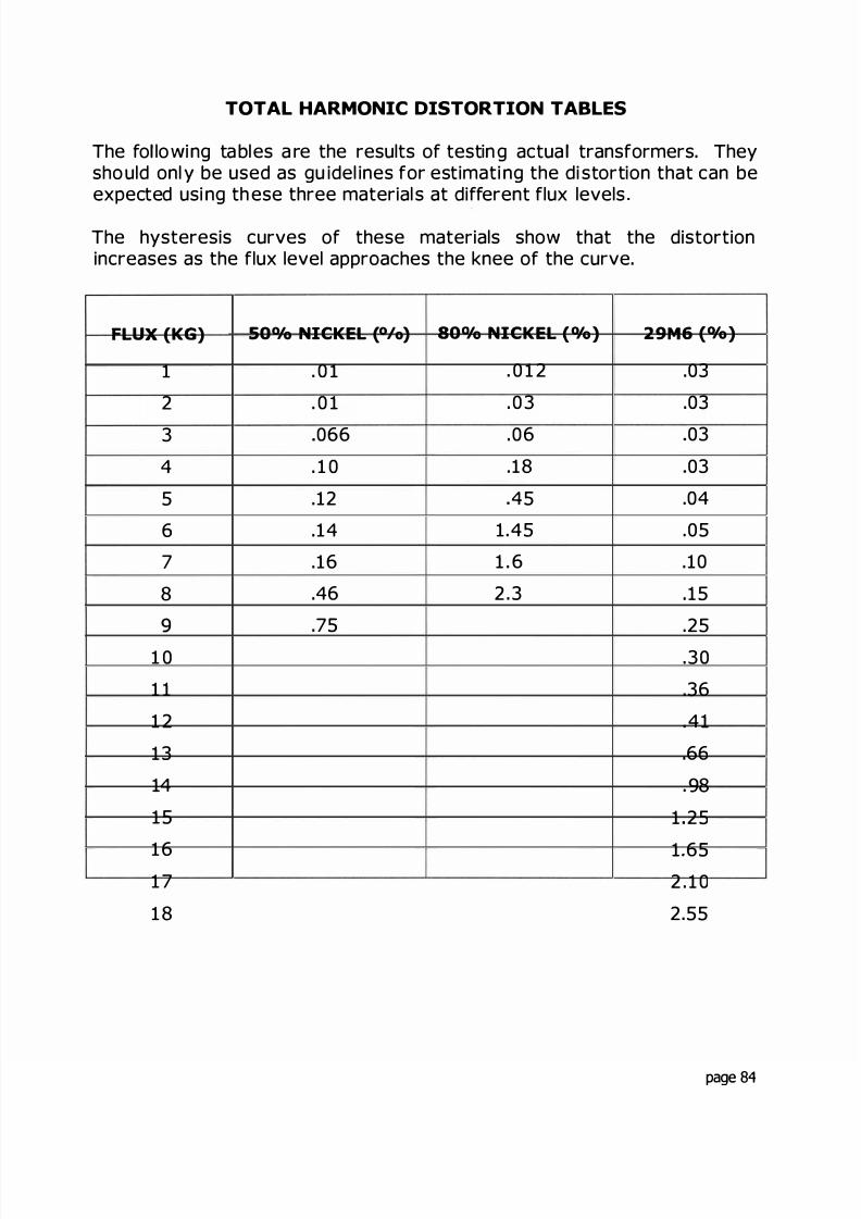
8/17/2019 Audio Transformer Design Manual - Robert G. Wolpert (2004)
http://slidepdf.com/reader/full/audio-transformer-design-manual-robert-g-wolpert-2004 86/117
TOTAL HARMONIC DISTORTION TABLES
The fo lowing ta bles a re the results of testin g actua transformers. Theysho uld onl y be used as gu idel ines for estimati ng the di stortion that can beexpected usi ng th ese three material s at different flux levels .
The hysteresis curves of these materials show that the distortionincreases as the flux level approaches the knee of the curve.
FLUX (KG) SO /o NICKEL ( /o) 80 /o NICKEL ( /o) 29M6 ( /o)
1 . 0 1 . 0 1 2 .03
2 . 0 1 . 0 3 .03
3 066 .06 03
4 . 1 0 .18 03
5 .12 .4 5 .04
6 .14 1.45 .05
7 .16 1 . 6 .10
8 .46 2 .3 15
.75 .25
1 0 .30
1 1 .36
1 2 .41
13 66
14 . 98
15 1 25
16 1 651 7 2 . 1 0
1 8 2.55
page 84

8/17/2019 Audio Transformer Design Manual - Robert G. Wolpert (2004)
http://slidepdf.com/reader/full/audio-transformer-design-manual-robert-g-wolpert-2004 87/117
The following tables show the turns of each size of wire that can be fittednto different sizes of lam inations, both layer woun d an d bo bbin woun d
These tables w l be a he lp i n determin in g the possibi l ty of fit in a designafter the turns and w re s zes are chosen and before spending a lot oftime calculat ing the fi l l .
For exam ple, i f th e design shown in 5. 3 pages 20 and 2 was stopped atthe point, page 23 where 390 turns of #23 wire was determ ned for thepr imary and the EI- 2 Lam nation Table in the Appendix is consulted, itcan be shown that it will fit , 390 / 848 x 100 = 46° Th s s le ss than
/2 of the ava l ab le spa ce and s a bout r gh t for the p rim ary w n din g in anormal design.
These tables can save a lot of design time that might be necessary in
juggl ng between turns, wire sizes and laminat on sizes However, whereextens ve interleaving is used, 46° f l l for the pri ma ry win din g mi ghtresu lt in a t g ht f t.
page 85
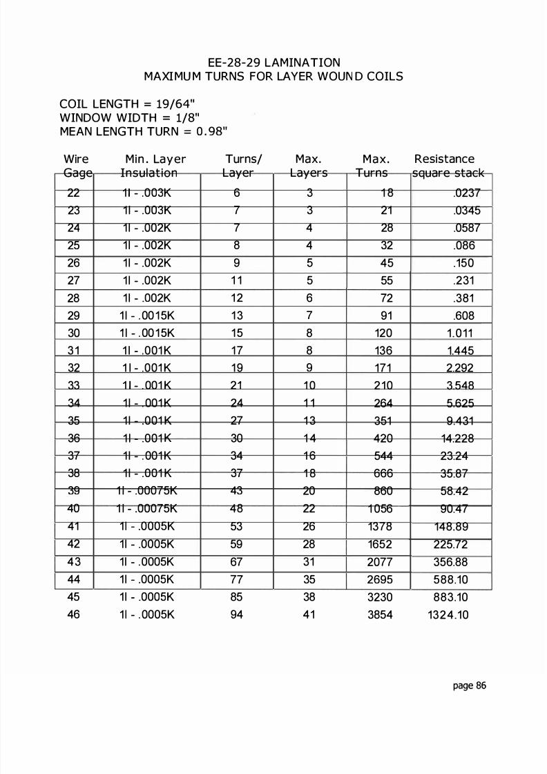
8/17/2019 Audio Transformer Design Manual - Robert G. Wolpert (2004)
http://slidepdf.com/reader/full/audio-transformer-design-manual-robert-g-wolpert-2004 88/117
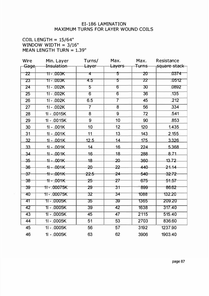
8/17/2019 Audio Transformer Design Manual - Robert G. Wolpert (2004)
http://slidepdf.com/reader/full/audio-transformer-design-manual-robert-g-wolpert-2004 89/117
EI- LAMINA IONMAXIM UM U RNS FOR LAYER WOUN D COILS
COIL LENG H = / 4"WINDOW WID H = /
MEAN LENG H TURN = "
WireGage
22232252627282930313233
33 5
36373839
01
24 3
56
Min LayerInsulation
1 - 003K1 - 003K1 002K1 002K1 - 002K1 - 002K
1 - 001 5K1 - 00 1 5K1 - 001 K1 - 001 K1 - 001 K1 - 001 K
1 00 1 K1 - 001 K1 - 001 K1 001 K1 - 001 K
1 - 00075K1 - 00075K1 0005K
1 - 0005K1 - 0005K1 - 0005K1 0005K1 - 0005K
Turns/Layer
4 .5
56
6 57891 01 1
12 51
1 61820
22 525293235
3 9
5515663
Max.Layers
55667891 01 21 311 6
1 82022227313 4
39
27
535 7
62
Max Resistanceurns square stack
20 03722 051230 089236 135
5 21256 3372 5 190 853
120 1 351 3 2 155175 3 32622 5 368
288 8 71360 13 72
0 2 1 15 0 32 72675 51 57899 86 62
1088 132 201365 209 20
1638 317 02 11 5 515 02703 836 603192 1237 903906 1903 0
page 87

8/17/2019 Audio Transformer Design Manual - Robert G. Wolpert (2004)
http://slidepdf.com/reader/full/audio-transformer-design-manual-robert-g-wolpert-2004 90/117
EI LAMINATIONMAXIMU M TURNS FOR LAYER WOUN D COILS
COIL LENGTH = / "WIN DOW WIDTH = / "MEAN LENGTH TURN= . "
WireGage
222324252627282930313233
3 4
353637383 9
4041
4243444546
Min LayeInsulation
1 - 0025K1 - 003K1 - 002K1 - 002K1 - 002K1 - 002K
- 00 5 K- 001 5 K
1 - 001 K1 - 00 K1 - 001 K1 - 001 K
1 - 001 K1 - 001 K1 - 001 K1 - 001 K
1 - 00075K1 - 00075K1 - 00075K1 - 00075K
1 - 00075K1 - 00075K1 - 0005K1 - 0005K1 - 0005K
Turns/Layer
91 0
1 51 3
14 51 61 82023
25 528
31 5
3640 545
50 556657 3
80
881011 1 5127
41
MaxLayers
55667891 01 21 31 41 6
1 820224273 13 4
39
4247535 7
62
Max ResistanceTurns square stack
45 084150 116569 205278 2925
101 4774128 7631162 1 218200 1 895276 3 30331 5 00392 7 45504 12 08
648 19 588 1 0 30 87945 45 41
1 2 2 73 441 5 1 2 115 502 0 1 5 194 202482 301 603120 478 00
3696 716 304747 1 1 57 006095 1886 507239 2807 408742 4260 00
page 88

8/17/2019 Audio Transformer Design Manual - Robert G. Wolpert (2004)
http://slidepdf.com/reader/full/audio-transformer-design-manual-robert-g-wolpert-2004 91/117

8/17/2019 Audio Transformer Design Manual - Robert G. Wolpert (2004)
http://slidepdf.com/reader/full/audio-transformer-design-manual-robert-g-wolpert-2004 92/117

8/17/2019 Audio Transformer Design Manual - Robert G. Wolpert (2004)
http://slidepdf.com/reader/full/audio-transformer-design-manual-robert-g-wolpert-2004 93/117
EI LAMI NATIO NMAXIMU M TURNS FOR LAYER WOUN D COILS
COIL LENGTH = /2"WINDOW WIDTH = / "
MEAN LENGTH TURN = 2. "WireGage
Min LayerInsulation
Turns/Layer
0 1 - 005K 1 31 1 - 005K 1 5
1 003K 1 63 1 - 003K 1 84 1 - 00 K 15 1 - 00 K 36 1 - 00 K 67 1 - 00 K 98 1 - 00 1 5K 319 1 - 001 5 K 36
30 1 - 001 K 4031 1 - 00 1 K 4 4
3 1 - 001 K 4933 1 - 001 K 5534 1 - 001 K 6335 1 - 001 K 7136 1 001 K 783 7 1 001 K 8538 1 - 00 1 K 9639 1 - 00075K 107
40 1 - 00075K 1 1 941 1 - 0005K 1334 1 - 0005K 15
MaxLayers
67891 01 111 51 61 70
47
303437
404451
566674
Max. ResistanceTurns square stack
78 1 8 1 0105 30791 8 473416 7558
1 0 1 3553 1 8767
3 1 917435 5 130496 7 37661 11 476800 18 9968 8 86
1176 44 41485 70 411890 113 0
414 18 0886 74 33
3400 407 584 4 638 485 4 57 1040 1
6664 160 08778 661 37
11 48 4300 0
page 91

8/17/2019 Audio Transformer Design Manual - Robert G. Wolpert (2004)
http://slidepdf.com/reader/full/audio-transformer-design-manual-robert-g-wolpert-2004 94/117
EI- LAMI NATIONMAXIMUM TURNS FOR LAYER WOUND COILS
COIL LENGTH = / "WINDOW WIDTH = / "
MEAN LENGTH TURN = "WireGage
Min LayerInsulation
Turns/Layer
20 1 - 003K 1 52 1 1 - . 003K 1 722 1 - . 003K 2023 1 . 003K 2224 1 002K 2425 1 - 002K 2726 1 - 002K 3127 1 - 002K 3428 1 - .001 5 K 3929 1 .001 5K 4330 1 - 001 K 4831 1 - .001 K 5 4
32 1 - .001 K 5933 1 - .001 K 673 4 1 - 001 K 7635 1 - 001 K 8636 1 - 001 K 9 5
37 1 - 001 K 10738 1 - 00075K 11939 1 - 00075K 127
40 1 - 00075K 15441 1 - 00075K 16842 1 - . 0005K 18743 1 - 0005K 21444 1 - . 0005K 243
MaxLayers
67891 01 1121 31 51 71 921
23262932353 9
4550
5564707 8
87
Max ResistanceTurns sq uare stack
90 .237511 9 .396160 .6714198 1 .048240 1 .602297 2.50372 3 947442 5.915585 9.87731 15.559 1 2 24.47
1134 38.36
1357 58 101742 93.712204 118.602752 235.403325 358 604173 567 605805 995.506350 1373.30
8470 2310.000752 3698.50
1 3090 5694.0016692 9131.002 11 4 1 14687.00
page 92
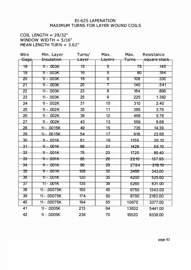
8/17/2019 Audio Transformer Design Manual - Robert G. Wolpert (2004)
http://slidepdf.com/reader/full/audio-transformer-design-manual-robert-g-wolpert-2004 95/117
EI LAMI NATIONMAXIM UM TURNS FOR LAYER WOU N D COILS
COI LENGTH = / "WINDOW WIDTH = / "MEAN ENGTH TUR N= . "
WireGage
1 81 9202122232425262 7
2829
303132333 4
353637
3839404142
Min ayerInsulation
1 - 003K1 - 003K1 - 003K1 - 003K1 - 003K1 - 003K1 - 002K1 - 002 K1 - 002K1 - 002K
1 - 00 1 5K1 - 00 1 5K
1 - 001 K1 001 K1 - 001 K1 - 001 K1 - 001 K1 001 K1 - 001 K1 - 001 K
1 - 00075K1 - 00075K1 - 00075K1 - 0005K1 - 0005K
Turns/Layer
1 51 61 82023253135394 3
495 4
6168758596
108120135
150174194213236
Maxayers
5567891 01 11 21 31 51 7
1 921232629323 5
39
45505 5
6470
Max ResistanceTurns squ are stack
7 5 14580 194
108 330140 541184 896225 1 382310 2 40385 3 76468 5 76559 8 68735 14 39918 22 66
1159 36 101428 56 101725 85 402210 137 952784 219 103456 343 004200 525 605265 831 00
6750 1343 008700 2183 00
1 0670 3377 001 3632 5441 0016520 8338 00
page 93

8/17/2019 Audio Transformer Design Manual - Robert G. Wolpert (2004)
http://slidepdf.com/reader/full/audio-transformer-design-manual-robert-g-wolpert-2004 96/117

8/17/2019 Audio Transformer Design Manual - Robert G. Wolpert (2004)
http://slidepdf.com/reader/full/audio-transformer-design-manual-robert-g-wolpert-2004 97/117
EI LAMINATIONMAXIM UM URNS FOR LAYER WOU N D COILS
COIL LENG H = /WIN DOW WID H = / 6"MEAN LENGTH TURN = 0
WireGage
Min. LayerInsulation
Turns/Layer
1 8 1 - 003K 221 9 1 - 003K 2520 1 003K 2821 1 - 003 K 3122 1 003K 3523 1 - 003K 3 9
24 1 - 002K 4425 1 - 002K 492 1 002K 5527 1 002K 12 8 1 - 00 1 5 K 929 1 - 00 1 5K 77
30 1 001 K 831 1 - 001 K 9 5
32 1 001 K 03 3 1 - 001 K 2034 1 - 001 K 133 5 1 - 001 K 533 1 001 K 1703 7 1 - 001 K 191
38 1 - 00075K 2 1 339 1 - 00075K 2440 1 - 00075K 27541 1 - 0005K 30242 1 0005K 334
Max.Layers
7891 01 11 21 411 71 92224
283134
384247515 7
5748193102
Max. Resistanceurns squ are stack
154 38200 7 3252 1 074310 1385 1 974 8 3 9
1 4784 10935 1 03
1 1 59 25 01518 41 381848 3 51
2408 104 402945 1 0 903 04 248 4045 0 39 305712 15 007191 993 708 70 1510 50
10887 2392 00
13845 3835 5018204 3 0 0022275 9814 002808 15 0 00340 8 23939 00
page 95
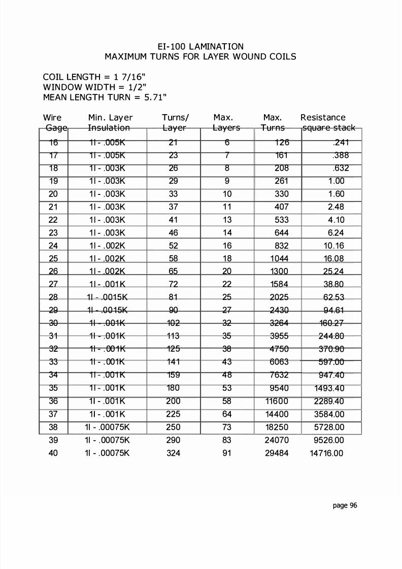
8/17/2019 Audio Transformer Design Manual - Robert G. Wolpert (2004)
http://slidepdf.com/reader/full/audio-transformer-design-manual-robert-g-wolpert-2004 98/117
EI AMINATIONMAXIM UM TU RNS FOR AYER WOU N D COILS
COIL ENGTH = / "WIN DOW WIDTH = / "
MEAN LENGTH TURN=
"
WireGage
Min LayerInsulation
Turns/Layer
1 6 1 - 005K 211 7 1 - 005K 231 8 1 - 003K 261 9 1 - 003K 2920 1 - 003K 3321 1 - 003K 3 7
22 1 - 003K 4123 1 - 003K 462 4 1 - 002K 5225 1 - 002K 5826 1 - 002K 6527 1 - 001 K 72
28 1 - 001 5K 8129 1 - 00 1 5K 9030 1 - 001 K 10231 1 - 001 K 11 332 1 - 00 1 K 12533 1 - 001 K 1413 4 1 - 001 K 15935 1 001 K 180
36 1 001 K 20037 1 - 001 K 22538 1 - 00075K 2503 9 1 - 00075K 29040 1 - 00075K 324
Max.ayers
67891 01 11 31 41 61 82022
25273235384 3
485 3
586 4
738391
Max ResistanceTurns square stack
1 26 241161 388208 632261 1 00330 1 60407 2 48533 4 1 0644 6 24832 1 0 1 6
1 044 16 081300 25 241584 38 80
2025 62 532430 94 613264 160 273955 244 804750 370 906063 597 007632 947 409540 1493 40
11600 2289 4014400 3584 0018250 5728 0024070 9526 0029484 14716 00
page 96
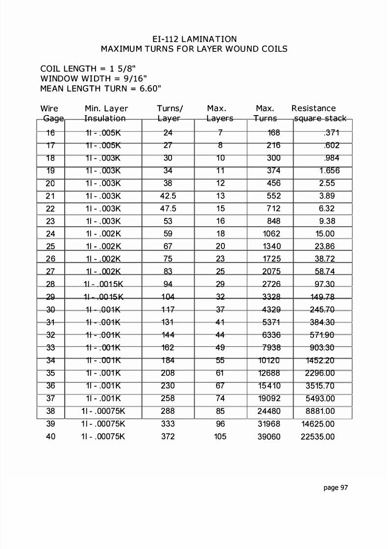
8/17/2019 Audio Transformer Design Manual - Robert G. Wolpert (2004)
http://slidepdf.com/reader/full/audio-transformer-design-manual-robert-g-wolpert-2004 99/117
EI LAMINATIONMAXIMU M TURN S FO R LAYER WOU N D COILS
COIL LENG H = 1 /WINDOW WI DTH = /MEAN LENG H URN = "
WireGage
1 61 7
89
202 1222324252627
2829303132333435
3637383940
Min. LayerInsulat ion
- 005K- 005K
1 - 003K1 - 003K1 - 003K
- 003K1 - 003K1 - 003K1 002 K1 002 K1 - 002K1 - 002K
- 001 5K- 00 15 K
1 - 001 K1 - 001 K1 - 001 K1 - 001 K1 - 00 1 K1 - 001 K
1 - 001 K1 001 K
- 00075K1 - 00075K1 00075K
u ns/Layer
2427303438
42 547 55359677 5
83
941 041 1 71311441621 84208
230258288333372
MaxLayers
781 01 11 21 31 51 61 8202325
2932374 1444 9
5561
677 4
8596
105
Max Resistanceurns square stack
168 3712 1 6 602300 984374 1 656456 2 55552 3 897 1 2 6 32848 9 38
1062 5 001340 23 86
725 38 722075 58 74
2726 97 303328 149 784329 245 705371 384 306336 571 907938 903 30
10120 1452 2012688 2296 00
15410 3515 7019092 5493 0024480 8881 0031968 14625 0039060 22535 00
page 97
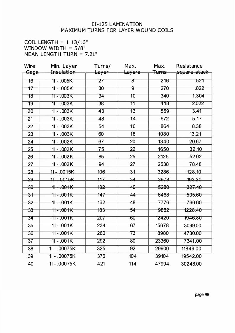
8/17/2019 Audio Transformer Design Manual - Robert G. Wolpert (2004)
http://slidepdf.com/reader/full/audio-transformer-design-manual-robert-g-wolpert-2004 100/117
EI LAMINATIONMAXIM U M TU RNS FOR LAYER WOU N D COILS
COIL LENGTH = / "WINDOW WIDTH = /MEAN LENGTH TURN = "
W reGage
M n LayerInsulat on
Turns/Layer
1 6 1 - 005K 271 7 1 - 005K 301 8 1 - 003K 341 9 1 - 003K 3820 1 - 003K 4321 1 - 003K 4822 1 - 003K 5423 1 - 003K 6024 1 - 002K 6725 1 - 002 K 7 5
26 1 002 K 8527 1 - 002 K 94
281 - 00 1 5K 106
29 1 001 5K 11 730 1 - 00 1 K 13231 1 00 1 K 14732 1 - 001 K 1623 3 1 - 00 1 K 1833 4 1 - 001 K 20735 1 - 00 1 K 234
36 1 - 001 K 26037 1 - 001 K 29238 1 - 00075K 32539 1 - 00075K 37640 1 00075K 421
Max.Layers
891 01 11 31 41 61 8202225273134404448546067
73809210411 4
Max. ResistanceTurns square stack
216 521270 822340 1 3044 1 8 2 022559 3 41672 5 17864 8 38
1080 13 211340 20 671650 32 102125 52 022538 78 483286 128 103978 193 205280 327 406468 505 607776 766 609882 1228 40
12420 1946 8015678 3099 00
18980 4730 0023360 7341 0029900 11849 0039104 19542 0047994 30248 00
page 98

8/17/2019 Audio Transformer Design Manual - Robert G. Wolpert (2004)
http://slidepdf.com/reader/full/audio-transformer-design-manual-robert-g-wolpert-2004 101/117
EI- LAMINATIONMAXIM UM TUR NS FOR LAYER WOU N D COILS
COIL LENGTH = "WINDOW WIDTH = / "
MEAN LENGTH TURN = "WireGage
1 3141 51617
1 81 92021222324
2526272829303132
333 4
Min LayerInsulation
1 - . 01 0K1 01 0K1 - 01 0K1 - . 007K1 - 007K1 - . 007K1 - . 005K1 - 005K1 - 005K1 - 005K1 - 005K1 - 003
1 - 0031 .0031 003
1 . 00 1 51 - 00 1 51 - .001 K1 - .001 K1 - 001 K
1 - 001 K1 - 001 K
Turns/Layer
1 9212429333 7
434854626978
889811 01231361531721 9 1
2 1 3241
MaxLayers
67881 01 11 21 41 51 82023
2629323 7
404 4
4953
5869
Max ResistanceTurns sq uare stack
114 .146147 .24192 39232 60330 1 .07407 1 .66516 2 65672 4.358 1 0 6 60
111 6 11.501380 17.901 794 29.50
2288 47.202842 74 003520 1 16.004551 189.005440 287 006732 445.008428 700.00
10213 1060.00
12354 1630.001 6629 2765 00
page 99

8/17/2019 Audio Transformer Design Manual - Robert G. Wolpert (2004)
http://slidepdf.com/reader/full/audio-transformer-design-manual-robert-g-wolpert-2004 102/117
EI- LAMINA IONMAXIM UM URNS FOR LAYER WOU ND COILS
COIL LENGTH = / "WINDOW WIDTH = /
MEAN LENG H TURN = "Wi eGage
1 314151 61 71 81 92021222324
2526272829303132
Min. LayerInsulation
1 - 0 0K1 - 001 K1 - 001 K
- 007K- 006K- 007K
1 - 005K1 - 005K1 - 005K1 - 003K1 003K1 - 002K
1 - 002 K1 - 002K1 002K
1 - 001 5K1 00 1 5K1 - 00 K1 - 001 K1 - 001 K
urns/Layer
2242733374475359
697786
9 7 1091211361511691902 1 5
Max.Layers
78891 11 21 31 51 7202226
2832354044485458
Max. Resistanceurns square stack
147 211 92 342 6 48297 84407 1 44492 2 20611 3 457 9 5 5 60
1003 9 001380 15 601694 24 002236 41 00
2716 63 503488 100 004235 153 005440 247 006644 381 008 11 2 583 00
1 0260 933 0012528 1435 00
page 100

8/17/2019 Audio Transformer Design Manual - Robert G. Wolpert (2004)
http://slidepdf.com/reader/full/audio-transformer-design-manual-robert-g-wolpert-2004 103/117
EE- - LAMINATIONMAXIM U M TURNS FOR BOBBIN WOU ND COILS ( ° o FILL)
M EAN LENGTH TU RN= "
WireGage
202122232425
2627282930313233
3 4
35363 7
383940414243444 5
46
Turns/Layer
7891 01 11 2
1 41 51 71 921242630
333 7
4146515865738090102118123
MaxLayers
223334
45567881 0
1 11 21 41 51 720222528313 5
4143
MaxTurns
141 627303348
567585
1 14147192208300
363444574690867
1 1 601430182522402790357048385289
Resistancesqua re stack
.0121
.01740373052007231325
.196325
.469955
1 .2862 .1172.8415.20
5.6912 3520 8029 7347.0082.80
111 .60164.80312.70450.00780.00
1 369.001 878 00
page 10 1
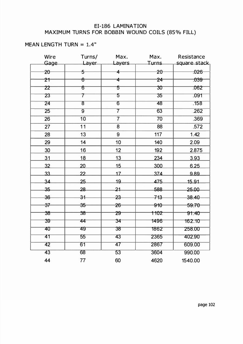
8/17/2019 Audio Transformer Design Manual - Robert G. Wolpert (2004)
http://slidepdf.com/reader/full/audio-transformer-design-manual-robert-g-wolpert-2004 104/117
EI- LAMINATIONMAXIMUM TURNS FOR BOBBIN WOUN D COILS ( ° o FILL)
MEAN LENGTH TURN= "
WireGage
202122232425
26272829303132333 4
35363 7
38394041424 3
44
Turns/Layer
566789
1 01 11 3141 61 82022
2528313538444 9
5561687 7
MaxLayers
445567
7891 01 21 31 51 7
1 9212326293438434 7
5 3
60
MaxTurns
202430354863
7088
117140192234300374
475588713910
1 102149618622365286736044620
Resistancesquare stack
026039062091158
.262
.369572
1 422 092.8753 936.259.89
15 9125 0038 4059 7091 .40
162 10258 00402.90609.00990.00
1540.00
page 102

8/17/2019 Audio Transformer Design Manual - Robert G. Wolpert (2004)
http://slidepdf.com/reader/full/audio-transformer-design-manual-robert-g-wolpert-2004 105/117
EI- LAMINATIONMAXIM U M TU RN S FOR BOBBIN WOU N D COILS ( ° o FILL)
M EAN LENG H TU RN= "
WireGage202122232425
262728293033233
3 4
353637
3839404142434445
urns/Layer0
2457
922427303 4
3742
4753
5865728392103114127145167
MaxLayers
344556
7891 01 11 21 41 6
1 720222527323 5
4044505766
Maxurns
3044487075
102
1 331682 1 6270330408518672
799060276
1 6252656294432204120501663508265
11022
Resistancesquare stack
03760700963
.176
.2382408
.6751 071 722.724.246.58
10 4016 72
25 8043.3565 40
1 02 9055 90
278.00429.00673 50
1029 001683 002413 004640 00
page 103
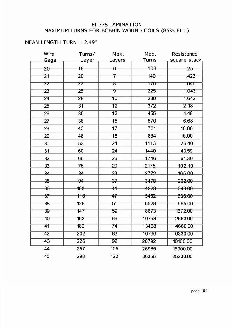
8/17/2019 Audio Transformer Design Manual - Robert G. Wolpert (2004)
http://slidepdf.com/reader/full/audio-transformer-design-manual-robert-g-wolpert-2004 106/117

8/17/2019 Audio Transformer Design Manual - Robert G. Wolpert (2004)
http://slidepdf.com/reader/full/audio-transformer-design-manual-robert-g-wolpert-2004 107/117
E E - LAMINATIONMAXIM U M TUR NS FOR BOBBIN WOU ND COI LS ( ° o FILL)
MEAN LENGTH TURN= 1 6"
WireGage
20222232425
227282930332333 4
3533 7
383940
4424 3
4445
Turns/Layer
24579
22242730343744 7
5259
472809
02
424
08
Max.Layers
5
789
0
34
82023
252832353945
5737894
MaxTurns
5572840537
2202 435420544
82008
30052
204825203 204 85202
49879380029 07484
Resistancesquare stack
0948
23083 24
954
542 3 53 945 89 35 00
22 7037 9
57 8593 2044 50
223 00344 00
04 0095 00
573 00224 003 3 005870 009 70 00
page 105

8/17/2019 Audio Transformer Design Manual - Robert G. Wolpert (2004)
http://slidepdf.com/reader/full/audio-transformer-design-manual-robert-g-wolpert-2004 108/117
EI- LAMINA IONMAXIMU M URN S FOR BOBB IN WOU N D COILS ( ° o FILL)
MEAN LENGTH URN= "
Wire
Gage202122232425262728293033233
3 4 3 5
3637383 9
4044243444 5
u ns/
Layer1 92124273034
3842475258667282
9103
226
140160178199220247281325
Max
Layers67891 01 11 41 41 61 820232528
323640455058647280901021 1 8
Max
urns114147
9224330037 4
532588752936
1 1601 5 1 818002296
291237084480567070009280
1 139214328
7600222302866238350
Resistance
squa e stack.319
5345856
1 362 1233 345 608.49
13 5020 7533 2255 5386 00
130 00
210.00328 00512 50800 00
1250.002830 003385.005240 008128 00
1 3130.0020430.0032200 00
page 106
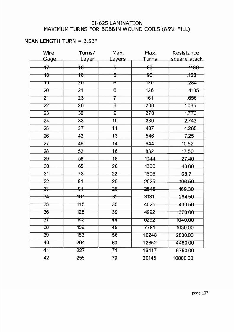
8/17/2019 Audio Transformer Design Manual - Robert G. Wolpert (2004)
http://slidepdf.com/reader/full/audio-transformer-design-manual-robert-g-wolpert-2004 109/117
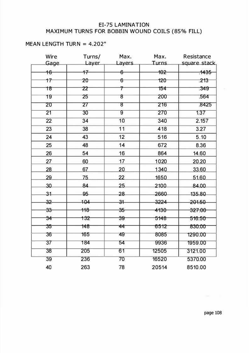
8/17/2019 Audio Transformer Design Manual - Robert G. Wolpert (2004)
http://slidepdf.com/reader/full/audio-transformer-design-manual-robert-g-wolpert-2004 110/117
EI- LAMINATIONMAXIMU M TURNS FOR BOBBIN WO U ND COILS ( ° o FILL)
MEAN LE NGTH TUR N= "
WireGage1 61 71 81 92021
2223242526272829
3031323334353637383 9
40
Turns/Layer
1 720222527303 4
3843485 4
606775
8495
1 0411 81 321481651 84205236263
MaxLayers
667889
1 01 11 21 41 61 72022
252831353 9
44495 4
6 17078
MaxTurns
1021201542002 1 6270
3404 1 85 1 6672864
1 0201 3401650
21002660322441305148651280859936
125051652020514
Resistancesquare stack
.1435
.213
.3 4 9
.564
.84251 37
2 1573 275 . 1 08 36
14.6020 2033.6051.60
84.00135.80201.50327.00516 50830 00
1290 001959.003121.005370.008510.00
page 108
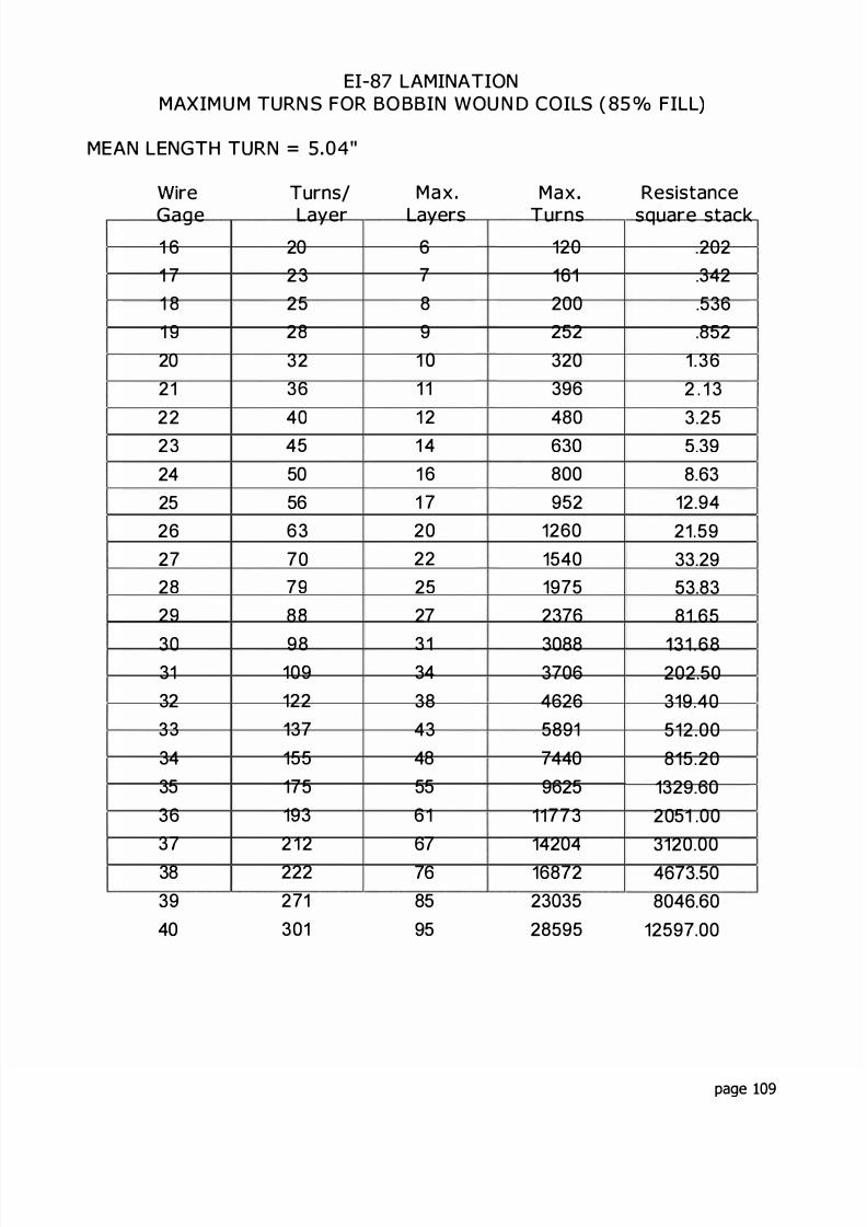
8/17/2019 Audio Transformer Design Manual - Robert G. Wolpert (2004)
http://slidepdf.com/reader/full/audio-transformer-design-manual-robert-g-wolpert-2004 111/117
EI- LAMINATIONMAXIM U M TURN S FOR BO BBIN WOU N D COILS ( ° o FILL)
MEAN LENGTH TURN= "
Wire
Gage1 61 71 81 920212223242526272829
3031323 3
3435363 7
383 9
40
Turns/
Layer202325283236404 5
5056637079
88
98109122
371551751932 1 2222271301
Max
Layers67891 01 11 21 41 61 720222527
3134384348556167768595
Max
Turns120161200252320396480630800952
1260154019752376
308837064626589174409625
1177314204168722303528595
Resistance
square stack202
.342
.536852
1 362 1 33.255.398 63
12 9421 5933 2953 8381 65
31 68202 50319.40512 00815 20
1329 602051 003120.004673 508046 0
12597 00
page 109
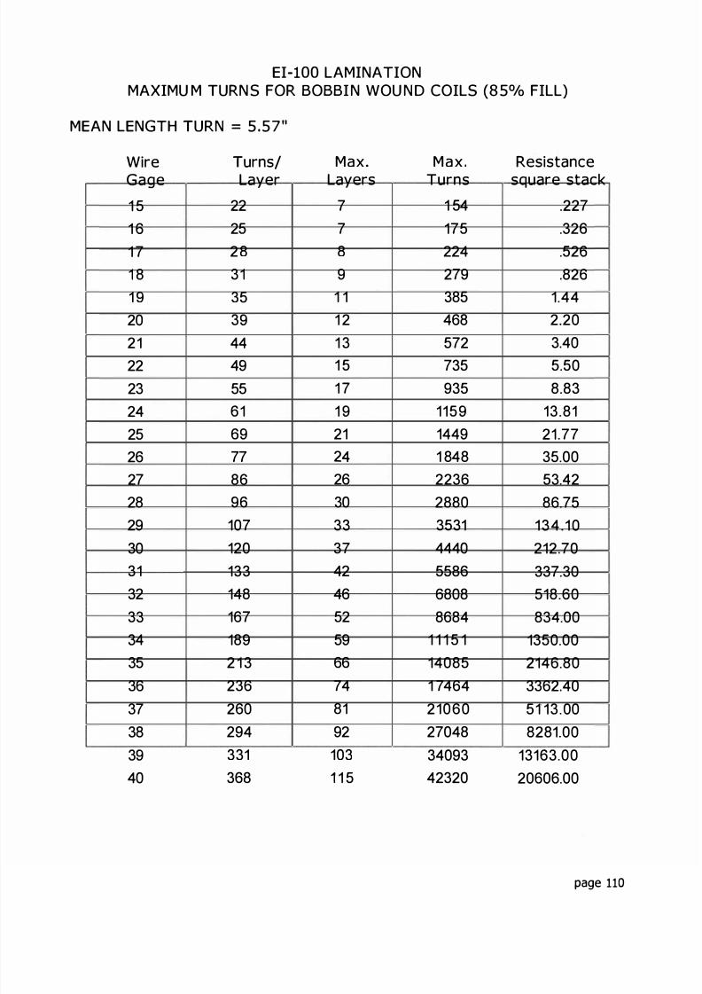
8/17/2019 Audio Transformer Design Manual - Robert G. Wolpert (2004)
http://slidepdf.com/reader/full/audio-transformer-design-manual-robert-g-wolpert-2004 112/117
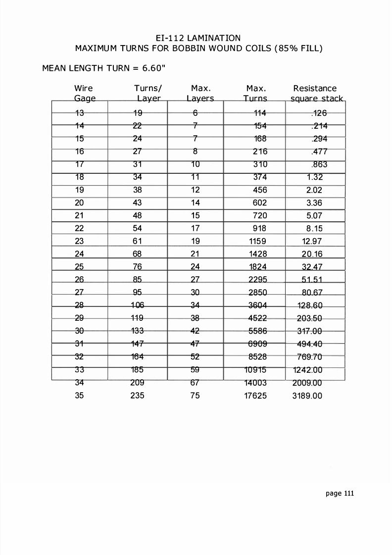
8/17/2019 Audio Transformer Design Manual - Robert G. Wolpert (2004)
http://slidepdf.com/reader/full/audio-transformer-design-manual-robert-g-wolpert-2004 113/117
EI- LAMINATIONMAXIMU M TURNS FOR BO BBIN WOUN D COILS ( ° o FILL)
M AN LENGTH TURN= . "
WireGage1 31 41 51 61 71 8
1 92022223242526
27282930313233343 5
Turns/Layer
1 92224273134
384348546 1687685
951 0611 9
33147164185209235
Max.Layers
67781 01 1
1 21 45
1 71 9212427
303 4
3842475259
6775
MaxTurns
1141541682 1 63 1 037 4
456602720918
1159428
18242295
285036044522558669098528
109151400317625
Resistancesquare stack
126214294477863
1 32
2 023 365 078 1 5
12 9720 1632 4751 51
80 67128 60203 50317 00494 40769 70
1242 002009 003189 00
page 111
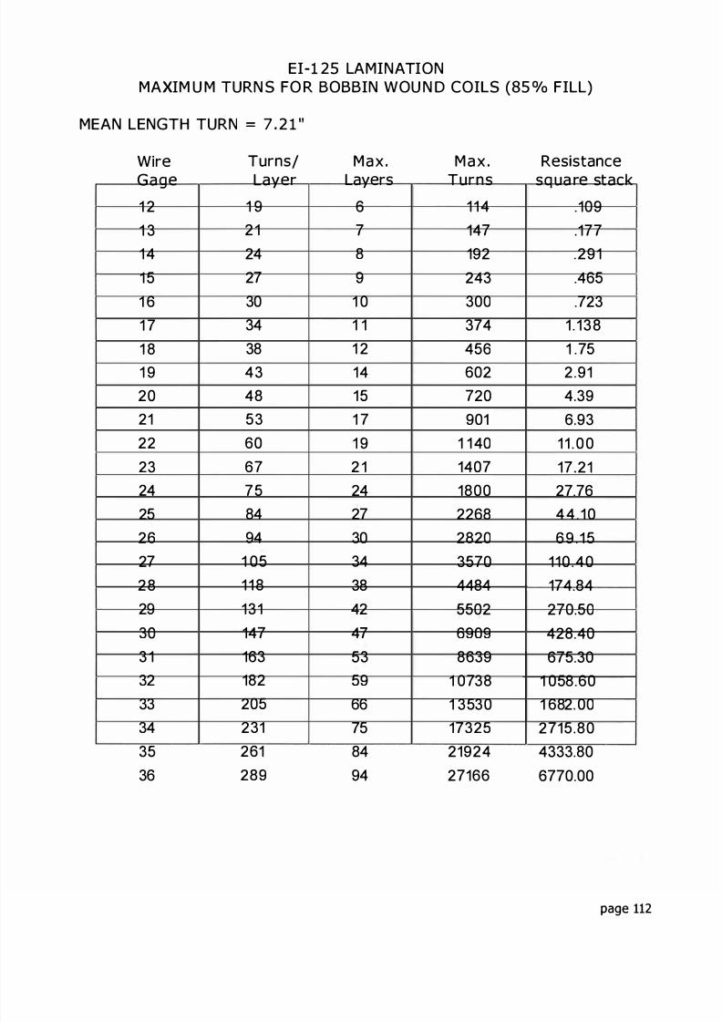
8/17/2019 Audio Transformer Design Manual - Robert G. Wolpert (2004)
http://slidepdf.com/reader/full/audio-transformer-design-manual-robert-g-wolpert-2004 114/117
EI- 5 LAMINATIONMAXIM U M TURN S FO R BOBBIN WOU N D COI S ( 5 °/o FILL)
MEAN LENGTH TURN= "
WireGage1 21 31 4
11 61 7
1 81 9202122
23242
26272829
303 1323334336
Turns
Layer1 92 1
2427
3034384348
36067784
941 011 8
131
14716318220231261289
MaxLayers
67891 01 11 21411 71 92 12427
3034
3842
475 3
5 9
6678494
M a x .Turns
11 4147192
243300374
4 6602720901
1 1 40140718002268
28203 704484
02
69098639
1 07381 3 30173221924
27166
Res stancesq ua re stack
109177291
46723
1 138
1 72 914 396 93
11 0 017 2127 764 4 1 0
6 9 1110 40174 84
270 0
428 4067 30
1 0 8 601 682 00271 804333 80
6770 00
page 112
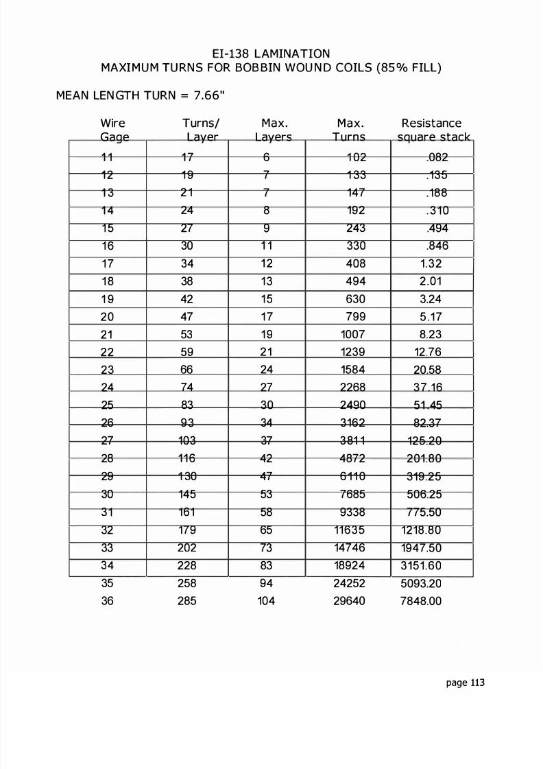
8/17/2019 Audio Transformer Design Manual - Robert G. Wolpert (2004)
http://slidepdf.com/reader/full/audio-transformer-design-manual-robert-g-wolpert-2004 115/117
EI- AMINA IONMAXIMU M U RNS FOR BOB BIN WOU N D COI S ( ° o FIL )
MEAN EN GTH URN= . "
WireGage
1234
1 51 6
1 71 81 9202222324
2526272829303132333 4
3536
urns/ayer
71 92 12427303 4
38424753
5 9
6674
839 3
036
1 30145161179202228258285
MaxLayers
67789
1
2131 51 71 9212427
303 4
3 7
424753586573839 4
104
MaxTurns
1 021 33
4792
243330
408494630799
10071239
5842268
24903 6238 148726 11 076859338
1163514746189242425229640
Resistancesquare stack
0821351883 1 0494846
1 322 013 245 178 23
12 7620 5837 16
5 4582 37
125 2020 80319 25506 25775 50
1218 801947 503 51 605093 207848 00
page 113

8/17/2019 Audio Transformer Design Manual - Robert G. Wolpert (2004)
http://slidepdf.com/reader/full/audio-transformer-design-manual-robert-g-wolpert-2004 116/117
EI- LAMINA IONMAXIMUM URNS FOR BOBBIN WOUN D COILS ( ° o FILL)
MEAN LENG H TURN= "
Wire
Gage1 01 11 21 31 41 51 61 71 81 9202 12223
242526272829303132
Turns/
Layer1 820232629333 7
41465158647281
961 0 11141261421581771972 1 9
Max
Laye s667891 01 21 31 51 71 9212326
293337414652586471
Max
Tu ns1081201 6 12082613304445 3 3
690867
1102134416562106
278433334218516665328216
102661260815549
Resistancesquare stack
.076
.106179292461
.7351.251.893 084 897.82
12 0418.7030.00
50 0075 52
120 49186 .10296.70470 60741 60
1 148.201786 00
page 114

8/17/2019 Audio Transformer Design Manual - Robert G. Wolpert (2004)
http://slidepdf.com/reader/full/audio-transformer-design-manual-robert-g-wolpert-2004 117/117