atv dvwk m 127 e pt2 appx1 4
TRANSCRIPT

ATV-DVWK-M 127 E, Part 2
January 2000 43
Appendix A1 Determination of the trench length and the supporting forces with draw-in/push-in of the pipe string (Case 2) Explanatory notes 1. Calculation model The required draw-in trench length lOC for Case 2 is determined: free length at upper edge of trench, draw-in with clearance between old pipe and liner. lOC results from the following conditions: • specified height difference hOC = invert of old pipe up to deflection roller at the edge of the trench
(minus clearance) • maximum 3 % elongation or compression set in the liner • maintenance of security against buckling of 1.5 for the pressed area of the liner. 2. Parameters • HDPE liner PN 3.2 to PN 10 • de = 160 to 1000 mm • stress-dependent moduli of elasticity:
Eσ=3 = 970 n/mm2 and Eσ=15 = 500 N/mm2 • mean temperature υ = +20°C • flat ground (ϕOC = 0) and negligible slope of old pipe (ϕP = 0) • clearance of the liner in the old pipe ∆h = di - dL,e = 0 to 0.5 ⋅ dL.e • no additional support. 3. Interpolation Interpolation may be carried out between curves.
010203040506070
0 5 10 15 20 25hOC/dL,e
min
l OC
/dL,
e
∆h/dL,e = 0
0.10.3
0.5
Diagram A1/1: Required trench length lOC for HDPE pipes PN 3.2 with draw-in into an old pipe
(clearance ∆h/dL,e)

ATV-DVWK-M 127 E, Part 2
44 January 2000
020406080
100120140160
0 5 10 15 20 25hOC/dL,e
A 1/g
L, A 2
/gL ∆h/dL,e = 0
0.1
0.3
0.5
0.5to0
A1
A2
Diagram A1/2: Support forces of HDPE pipes PN 3.2 at the old pipe (A1) and at the edge of the
trench (A2) with draw-in into an old pipe (clearance ∆h/dL,e)
010203040506070
0 5 10 15 20 25hOC/dL,e
min
l O
C /d
L,e
∆h/dL,e = 0
0.10.3
0,5
Diagram A1/3: Required trench length lOC for HDPE pipes PN 4 with draw-in into an old pipe
(clearance ∆h/dL,e)
ATV-DVWK-M 127 E, Part 2
January 2000 45
0
50
100
150
200
0 5 10 15 20 25hG/dL,e
A 1/g
L, A 2
/gL
∆h/dL,e = 00.1
0.3
0.5
0.5to0
A1
A2
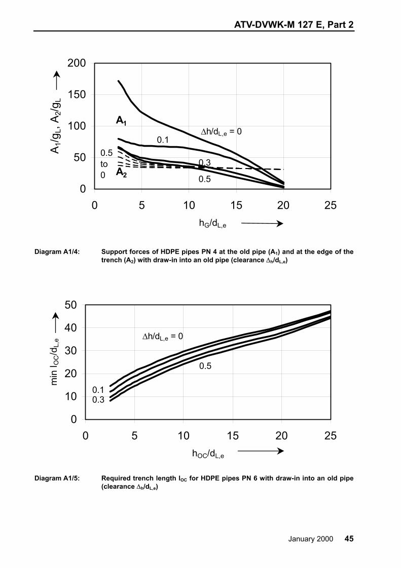
Diagram A1/4: Support forces of HDPE pipes PN 4 at the old pipe (A1) and at the edge of the
trench (A2) with draw-in into an old pipe (clearance ∆h/dL,e)
0
10
20
30
40
50
0 5 10 15 20 25hOC/dL,e
min
l OC/d
L,e ∆h/dL,e = 0
0.10.3
0.5
Diagram A1/5: Required trench length lOC for HDPE pipes PN 6 with draw-in into an old pipe
(clearance ∆h/dL,e)

ATV-DVWK-M 127 E, Part 2
46 January 2000
0
50
100
150
200
250
300
0 5 10 15 20 25hOC/dL,e
A1/g
L, A
2/gL
∆h/dL,e = 0
0.1
0.3
0.5
0.5to0
A1
A2
Diagram A1/6: Support forces of HDPE pipes PN 6 at the old pipe (A1) and at the edge of the
trench (A2) with draw-in into an old pipe (clearance ∆h/dL,e)
05
1015202530354045
0 5 10 15 20 25hOC/dL,e
min
l OC/d
L,e
∆h/dL,e = 0
0.10.3
0.5
Diagram A1/7: Required trench length lOC for HDPE pipes PN 10 with draw-in into an old pipe
(clearance ∆h/dL,e)

ATV-DVWK-M 127 E, Part 2
January 2000 47
0
50
100
150
200
250
300
0 5 10 15 20 25hOC/dL,e
A1/g
L, A
2/gL
∆h/dL,e = 0
0.1
0.3
0,5
0.5to0
A1
A2
Diagram A1/8: Support forces of HDPE pipes PN 10 at the old pipe (A1) and at the edge of the
trench (A2) with draw-in into an old pipe (clearance ∆h/dL,e)

ATV-DVWK-M 127 E, Part 2
48 January 2000
Appendix 2 Bending moment and normal force coefficients m and n for loading with annular space filling
Bending moment coefficient m
Normal force coefficient n
Bedding case Case A mW 1) mg’
Case B mF 2) mg’
Case A nW 1) ng
Case B nF 2) ng
I (rigid liner)
for sketches see m
Crown ϕ = 0° 0.250 0.500 0.750 -1.500 0.750 0.500 -0.750 0.500
Springer 75° 90° 105°
-0.197 -0.285 -0.320
-0.394 -0.571 -0.641
-0.320 -0.285 -0.197
0.641 0.571 0.394
0.303 0.215 0.180
-1.135 -1.571 -1.900
-1.820 -1.785 -1.697
1.900 1.571 1.135
Invert 180° 0.750 1.500 0.250 -0.500 1.250 -0.500 -1.250 -0.500
II/90° (flexible liner)
for sketches see m
Crown ϕ = 0° 0.184 0.367 0.182 -0.365 0.613 0.225 -1.389 1.777
Springer 75° 90° 105°
-0.161 -0.214 -0.214
-0.323 -0.429 -0.427
-0.214 -0.214 -0.161
0.427 0.429 0.323
0.268 0.215 0.215
-1.206 -1.571 -1.828
-1.785 -1.785 -1.732
1.828 1.571 1.206
Invert 180° 0.182 0.365 0.184 -0.367 0.611 -1.777 -1.387 -0.225
III/60° (separator, 2αA = 2 ⋅ 30°
for sketches see m
Crown ϕ = 0° 0.176 0.352 0.072 -0.413 0.599. 0.198 -1.506 2.011
Springer 75° 90° 105°
-0.159 -0.208 -0.204
-0.317 -0.416 -0.408
-0.204 -0.208 -0.159
0.408 0.416 0.317
0.264 0.215 0.219
-1.213 -1.571 -1.821
-1.781 -1.785 -1.736
1.821 1.571 1.213
Invert 180° 0.072 0.143 0.176 -0.352 0.494 -2.011 -1.401 -0.198
1) mF = -mW;nF = -nW Case A: sinking of the liner 2) mW = -mF; nW = -nF Case B: floating of liner
ATV-DVWK-M 127 E, Part 2
January 2000 49
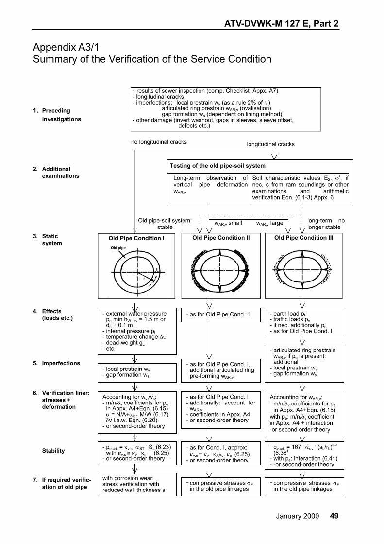
Appendix A3/1 Summary of the Verification of the Service Condition
1. Preceding
investigations
2. Additional examinations
3. Static system
4. Effects (loads etc.)
5. Imperfections
6. Verification liner: stresses + deformation
Stability
7. If required verific- ation of old pipe
- results of sewer inspection (comp. Checklist, Appx. A7) - longitudinal cracks - imperfections: local prestrain wv (as a rule 2% of rL) articulated ring prestrain wAR,v (ovalisation) gap formation ws (dependent on lining method) - other damage (invert washout, gaps in sleeves, sleeve offset, defects etc.)
Old Pipe Condition I Old Pipe Condition II Old Pipe Condition III
Old pipe-soil system:stable
long-term no longer stable
wAR,v large wAR,v small
Testing of the old pipe-soil system
Long-term observation of vertical pipe deformation wAR,v
Soil characteristic values E2, ϕ’, if nec. c from ram soundings or other examinations and arithmetic verification Eqn. (6.1-3) Appx. 6
- external water pressure pe min hW,Inv = 1.5 m or de + 0.1 m
- internal pressure pi - temperature change ∆υ - dead-weight gL - etc.
- as for Old Pipe Cond. 1 - earth load pE - traffic loads pv - if nec. additionally pe - as for Old Pipe Cond. I
- local prestrain wv - gap formation ws
- as for Old Pipe Cond. I, additional articulated ring pre-forming wAR,v
- articulated ring prestrain wAR,v if pe is present: additional
- local prestrain wv - gap formation ws
Accounting for wv,ws: - m/n/δv coefficients for pe
in Appx. A4+Eqn. (6.15)σ = N/A+αk ⋅ M/W (6.17)
- δv i.a.w. Eqn. (6.20) - or second-order theory
- as for Old Pipe Cond. I- additionally: account for
wAR,v - coefficients in Appx. A4 - or second-order theory
Accounting for wAR,v:- m/n/δv coefficients for pe
in Appx. A4+Eqn. (6.15) with pe: m/n/δv coefficient in Appx. A4 + interaction -or second order theory
- pe,crit = κv,s . αST . SL (6.23)
with κv,s ≅ κv . κs (6.25)
- or second-order theory
- as for Cond. I, approx:κv,s ≅ κv
. κARv. κs (6.25) - or second-order theory
no longitudinal cracks longitudinal cracks
with corrosion wear: stress verification with reduced wall thickness s
- compressive stresses σFin the old pipe linkages
- qv,crit = 167 . αqv . (sL/rL)
2.2
(6.38)
- with pe: interaction (6.41)- -or second-order theory
- compressive stresses σFin the old pipe linkages

ATV-DVWK-M 127 E, Part 2
50 January 2000
Appendix A3/2 Explanatory notes on old pipe conditions
Old pipe condition I II III
Longitudinal cracks - X X X
Visual differences between Old Pipe
Condition II-III
-
Slight ovalisation of cross-section
wAR,v < 3-5 %
Greater ovalisation of cross-section wAR,v > 3.5 %
(see also Appx. A6)
Arithmetic differences between Old Pipe
Conditions II-III
-
γ =
exist,v
Bh
Bh
v
qS
Sqmax ⋅
≥1.5
γ = exist,v
Bh
Bh
v
qS
Sqmax ⋅
< 1.5
(see 6.2, mainly loading from pE)
Fundamental loading of the liner
pe pe pE + pV (pE +PV) +pe
Liner/old pipe/soil system Loading effects Liner in
frictional connection mainly in positive locking
in frictional connection and positive locking
Substitute loading with pe = 0 (6.3.1.2)
hW,Inv = de + 0.1 m, at least hW,Inv = 1.5 m - -
Safety coefficient γnec (Table 4) 2.0 2.0 1.5 2.0/1.5
Soil parameters - - E2,ϕ’,K2 E2,ϕ’,K2
Concentration factor of soil above the pipe λP
(6.3.2.4) - - 0.75 (cracks before rehabilitation),
1.5 (cracks after rehabilitation)
Prestrain for circular cross-sections (6.3.1.1):
Local prestrain wv gap formation ws ovalisation wAR,v
≥ 2 % ≥ 0.5 %
-
≥ 2 % ≥ 0.5 %
≥ 3 %
01) 0
≥ 3 %
≥ 2 % with pe 0
≥ 3 %
Example DN 500 pe = 60 kN/m2 qv = 60 kN/m2,K2’ = 0.2
SBh [N/mm2] = - - 2.5 5
WAR,v = - 3 % 3 % 3 %
mpe,mq(sL = 7.5 mm) = 2) 2) 0.0253) ~ 0.015 ←
mpe,mq(sL = 10 mm) = 0.044 0.061 0.050 0.020 ←
mpe,mq(sL = 12.5 mm)= 0.035 0.050 0.0804) 0.040 ←
npe,nq = ca. -1 ca. -1 ca. -0.2 ← 1) As the bending strain as opposed to the normal force strain dominates with positive locking loading, an application of local
prestrain is not necessary. 2) With sL < 10 mm the required buckling safety is undercut. 3) With sL < 7.5 mm the required buckling safety is undercut. 4) Note: m(max sL) > m(min sL) applies, i.e. liners with greater wall thickness receive greater coefficients! For this comp. the water
pressure type of loading with reversed behaviour!
ATV-DVWK-M 127 E, Part 2
January 2000 51
The coefficients mpe and mq of the example show that, for Old Pipe Conditions I and II with external water pressure pe, stiffer liners are required. On the other hand, considering the danger of stability failure with Old Pipe Condition III and loading qv, non-rigid liners are an advantage.
Appendix 4 Bending moment and normal force coefficients mpe, npe and elastic deformation δv,el of the liner under external water pressure pe (Old Pipe Conditions I and II).
Explanatory notes 1. Arithmetical model of the liner-old pipe system • Rigidly bedded 360° annulus (plain framework) with rigid and movable bearings with prestrain and
annular gap • Exclusion of tensile and tangential forces between liner and old pipe (friction-free contact) • Truly normal loading through external water pressure pe (unit weight γW = 10 kN/m3) • Disregarding of the dead-weight of liner to be on the safe side (γL = 0) • Iteration of the non-linear pressure bending and contact problem • Load factor 2, following successful iteration the stress resultants are divided by 2 • As a rule the invert of the liner is relevant with small water pressure possibly the crown. 2. Parameters • Elasticity module EL = 1800 N/mm2
For EL > 1800 N/mm2 the coefficients lie on the safe side, for 1500 N/mm2 ≤ EL ≤ 3000 N/mm2 the deviation with mpe is less than 10 %.
• Local prestrain wv = 2 % of the liner radius, extension 40 % in the invert. • Annular gap ws = 1 % of the liner radius (the coefficients for smaller annular gaps lie on the safe side). • Old Pipe Condition II: articulated ring prestrain wAR,v = 3 % of the liner radius (ovalisation). 3. Interpolation of coefficients • For the normal force coefficients npe no interpolation is required as this are approximately constant.
npe = -0.8 applies with verification of tensile stresses, npe = -1.1 applies with verification of compressive stresses.
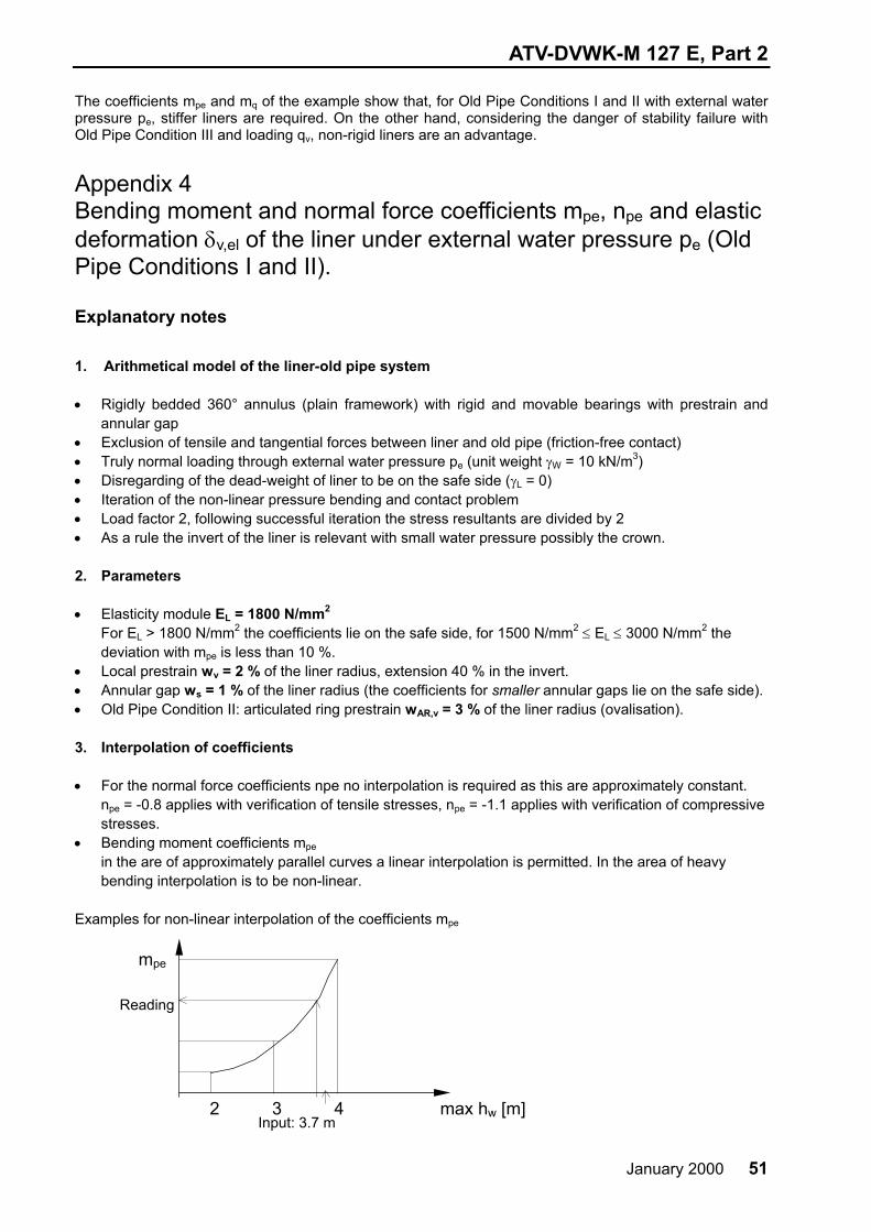
• Bending moment coefficients mpe in the are of approximately parallel curves a linear interpolation is permitted. In the area of heavy bending interpolation is to be non-linear.
Examples for non-linear interpolation of the coefficients mpe 2 3 4 max hw [m]
mpe
Input: 3.7 m
Reading

ATV-DVWK-M 127 E, Part 2
52 January 2000
0,00
0,02
0,04
0,06
0,08
0,10
0,12
1 2 3 4 5 6 7max hw above invert [m]
mpe
sL [mm] =
6.5
5Invert
Crown (I and II)
DN 250Old Pipe Condition IIOld Pipe Condition I
53.5 6,5
Diagram A4/1: Bending moment coefficients mpe for liners under external water pressure pe, old
pipe DN 200, Old Pipe Conditions I and II; liner EL = 1800 n/mm2
0,00
0,02
0,04
0,06
0,08
0,10
0,12
1 2 3 4 5 6 7max hw above invert [m]
mpe
sL [mm] =
6.5
5Invert
Crown (I and II)
DN 250Old Pipe Condition IIOld Pipe Condition I
53.5 6.5
Diagram A4/2: Bending moment coefficients mpe for liners under external water pressure pe, old
pipe DN 250, Old Pipe Conditions I and II; liner EL = 1800 n/mm2

ATV-DVWK-M 127 E, Part 2
January 2000 53
0,00
0,02
0,04
0,06
0,08
0,10
0,12
1 2 3 4 5 6 7max hw above invert [m]
mpe
sL [mm] = 5
7,5
10
7.5
510
Invert
Crown (I and II)
DN 300Old Pipe Condition II
Old Pipe Condition I
Diagram A4/3: Bending moment coefficients mpe for liners under external water pressure pe, old
pipe DN 300, Old Pipe Conditions I and II; liner EL = 1800 n/mm2
0,00
0,02
0,04
0,06
0,08
0,10
0,12
1 2 3 4 5 6 7max hw above invert [m]
mpe
sL [mm] =
10
12.510
7.5 12.5
Invert
Crown (I and II)
DN 400Old Pipe Condition II
Old Pipe Condition I
Diagram A4/4: Bending moment coefficients mpe for liners under external water pressure pe, old
pipe DN 400, Old Pipe Conditions I and II; liner EL = 1800 n/mm2

ATV-DVWK-M 127 E, Part 2
54 January 2000
0,00
0,02
0,04
0,06
0,08
0,10
0,12
1 2 3 4 5 6 7max hw above invert [m]
mpe
sL [mm] =
10
12.5
10
7.5 12.5
Invert
Crown (I and II)
DN 500Old Pipe Condition II
Old Pipe Condition I
Diagram A4/5: Bending moment coefficients mpe for liners under external water pressure pe, old
pipe DN 500, Old Pipe Conditions I and II; liner EL = 1800 n/mm2
0,00
0,02
0,04
0,06
0,08
0,10
0,12
1 2 3 4 5 6 7max hw above invert [m]
mpe
sL [mm] = 10
12.5
15
12.5
10 15
Invert
Crown (I and II)
DN 600Old Pipe Condition IIOld Pipe Condition I
Diagram A4/6: Bending moment coefficients mpe for liners under external water pressure pe, old
pipe DN 600, Old Pipe Conditions I and II; liner EL = 1800 n/mm2

ATV-DVWK-M 127 E, Part 2
January 2000 55
0
1
2
3
4
5
1 2 3 4 5 6 7max hw above invert [m]
d v,e
l [%
]
sL [mm] = 3.5
6.5
5
DN 200Old Pipe Condition IIOld Pipe Condition I
Diagram A4/7: Elastic deformation δv,el for liners under external water pressure pe, old pipe DN 200,
Old Pipe Conditions I and II; liner EL = 1800 n/mm2
0
1
2
3
4
5
1 2 3 4 5 6 7max hw above invert [m]
d v,e
l [%
]
sL [mm] = 3.5
6.5
5
DN 250Old Pipe Condition IIOld Pipe Condition I
Diagram A4/8: Elastic deformation δv,el for liners under external water pressure pe, old pipe DN
250, Old Pipe Conditions I and II; liner EL = 1800 n/mm2

ATV-DVWK-M 127 E, Part 2
56 January 2000
0
1
2
3
4
5
1 2 3 4 5 6 7max hw above invert [m]
d v,e
l [%
] sL [mm] = 5
10
7.5
DN 300Old Pipe Condition IIOld Pipe Condition I
Diagram A4/9: Elastic deformation δv,el for liners under external water pressure pe, old pipe DN 300,
Old Pipe Conditions I and II; liner EL = 1800 n/mm2
0
1
2
3
4
5
1 2 3 4 5 6 7max hw above invert [m]
d v,e
l [%
]
sL [mm] = 7.5
12.5
10
DN 400Old Pipe Condition IIOld Pipe Condition I
Diagram A4/10: Elastic deformation δv,el for liners under external water pressure pe,
old pipe DN 400, Old Pipe Conditions I and II; liner EL = 1800 n/mm2

ATV-DVWK-M 127 E, Part 2
January 2000 57
0
1
2
3
4
5
1 2 3 4 5 6 7max hw above invert [m]
d v,e
l [%
]
sL [mm] = 7.5
12.5
10
DN 500Old Pipe Condition IIOld Pipe Condition I
Diagram A4/11: Elastic deformation δv,el for liners under external water pressure pe,
old pipe DN 500, Old Pipe Conditions I and II; liner EL = 1800 n/mm2
0
1
2
3
4
5
1 2 3 4 5 6 7max hw above invert [m]
dv,e
l [%
]
sL [mm] = 10
15
12.5
DN 600Old Pipe Condition IIOld Pipe Condition I
Diagram A4/12: Elastic deformation δv,el for liners under external water pressure pe,
old pipe DN 600, Old Pipe Conditions I and II; liner EL = 1800 n/mm2