atsc 8vsb over-the-air smpte - sf hdtvsite.ieee.org/scv-ces/files/2015/06/ntsc_8vsb.pdf · hdtv...
TRANSCRIPT

1
ATSC 8VSB Over-the-Air HDTV
IEEE June 27, 2006
Roy Trumbull – Broadcast Engineer – [email protected]
Retired assistant chief engineer KRON-TV
Diagrams courtesy of www.atsc.org, www.opencable.com, www.zenith.com , www.motorola.com, www.terayon.com, www.trivenidigital.com
SMPTE - SF
• Meetings are at various venues– June meeting was at ILM– Majority of meetings are on the Peninsula
• SF website: members.aol.com/SMPTEsf– Anyone can sign up to our listserver for
notification of posted meetings.• National website: www.smpte.org
Information on the Webwww.atsc.org (Advanced Television Systems Committee)
click: News & Information or Standards click: Papers
There are numerous downloadable pdf files at this site including:
“Status of Digital Cable Interoperability” – outlines problems and lists many reference documents
www.opencable.com (a Cablelabs site)
click: Documents
click: “Open Cable Overview” and PDF file
8VSB Seminars
• 1 Day Seminars• Conducted by Gary Sgrignoli formerly with
Zenith.• For information: www.MSWdtv.com• [email protected]

2
Stations on Air
NTSC DTVKTVU 2 56KRON 4 57KPIX 5 29KGO 7 24KQED 9 30KNTV 11 12KDTV 14 51KBWB 20 19KTSF 26 27
NTSC DTVKICU 36 52KCNS 38 39KBHK 44 45KSTS 48 49KKPX 65 41KTLN 68 47
Nationwide 1566 Stations are broadcasting DTV
San Francisco-Oakland-San Jose Stations
Note Adjacent ChannelsDTV Adj.
KTVU 56 57 (DTV)KRON 57 56 (DTV)KPIX 29 30 (DTV)KGO 24 25 (both)KQED 30 29 (DTV)KNTV 12 11 (NTSC)KDTV 51 50 (NTSC)KBWB 19 20 (NTSC)KTSF 27 26 (NTSC)
DTV Adj.KICU 52 51 (DTV)KCNS 39 38 (NTSC)KBHK 45 44 (NTSC)KSTS 49 48 (NTSC)KKPX 41 42 (NTSC)KTLN 47 48 (NTSC)
NTSC Ch 48 has DTV adj. above and belowDTV Ch 51 has NTSC Ch 50 below and DTV Ch 52 above
Taboo ChannelsUnder NTSC rules there were minimum distances before co-channels and adjacent channels could be assigned. Also relationships of 2, 3, 4, 5, 7, 8, 14, 15 channels removed (taboo channels) weren’t permitted because of known frequency beats.
Adjacent channels weren’t assigned in the same market and the taboo relationships resulted in many channels not being used at UHF. All that is just a memory.
To provide “loaner channels” for the DTV transition. Minimum spacing rules and taboo rules were made secondary to the need toprovide channels. Some DTV assignments definitely interfere with NTSC co-channels.
Adjacent Channels Co-Located
Greatest harm is done when a strong taboo channel interferes with a weak desired channel
For this reason, the majority of the adjacent channel assignments were co-located.
Example: Adjacent channels at Sutro Tower
19 –20, 29-30, 38-39, 44-45, 56-57

3
Loaner Channels
• During transition to DTV, each NTSC station is loaned an additional channel
• At end of transition (2009), one channel is kept
• Channels above 51 go away• DTV stations assigned above 51 will have
to construct facilities twice
No Room For Each Station to Mount a New Antenna
Tower space at a premium
Room for antennas and transmission lines
Building Space Tight
Need to add second transmitter for DTV
Additional AC power capacity
Additional HVAC
Space needed for heat exchanges for water cooled transmitters
SolutionsBuild a totally new shared facility for a group of stations
Example: DTV Utah
New Tower & New Building
Multiple stations share common antennas by using diplexers
Example: Sutro Tower
Four stacked panel antennas with two to three stations per antennas
Pattern has three overlapping lobes like a clover with the stem being a null toward the ocean
Hardware required
• High power lo pass filter at xmitter output• Mask filter to control out of channel
emissions• Combiner with ports for each station using
the antenna• Switched dummy load for testing

4
Channel Skirts
• -47 DB below in-band average transmitted power at channel edge
• Using typical averaging function on spectrum analyzer this appears as -36 DB, 11 DB below theoretical average power
• Out of band emissions -110 DB >6 MHZ from channel edge
Sutro DTV Antenna Stack
Stack
DTV Stack
Stack
IOT TransmittersInductive Output Tubes
Cousins of Klystrons
Water Cooled - Actually Bug Juice Cooled - Industrial Grade Antifreeze (Dow & Union Carbide products)
Operating Voltage is 35KV at 1 to 2 amps
Mains voltage is 480 volts 3 phase
When transmitters become mismatched to the transmission line thedamage requires replacing the transmission line.
VSWR detection is needed between the combiner and the transmission line.

5
IOT Mounted in Carriage IOT Tuning
– Input cavity extremely critical. Best tuned using a network analyzer for centering and BW
– Input tuning impacts ability to do linear correction of flatness
– Output tuning is staggered with lower and upper half of channel tuned for flatness and minimum saddle at overlap
– Tuning of channel skirts is very soft
Cooling Pumps Pass Through ReceiverTo move an off-Air DTV to a cable channel without demodulating, the receiver must be a double conversion type ( 2 Ifs) to avoid unwanted beats. It should have a filter capable of removing adjacent channels without distorting the passband or adding phase distortion.
The conversion from IF to cable channel must be linear and not add distortions to the signal.
The output must be filtered to avoid having the signal interfere with adjacent channels.

6
NTSC Vs 8VSB Factors Involved in 8VSB DesignUnfriendly Environment:
Received signal isn’t constant - varies over time. Multipath is a problem and may be dynamic in natureTransmission path is subject to static, burst noise and to noise from intergalactic noise sources.
Transmission complexity must be confined to the transmit end so that a simple receiver with defined characteristics can be usedData packets must be sent non sequentially and encoded with forward error correction so that the signal can be reconstructed if parts of it are missing.The need to keep the over the air data robust limits the number of symbol levels to just 8 versus 32, 64, 128, and 256 for QAM via fiber.
S/N Budget
• Output to xmit antenna should be maintained at >27DB S/N using linear and non-linear correction
• Receiver needs >15.2 DB S/N to avoid cliff effect
NTSC CarriersThree Carriers:
Visual – 1.25 MHz from channel bottom
(Bottom 1.25 MHz is a vestige of the lower sideband. From 1.25 MHz up is the upper sideband.)
Chroma – 3.58 MHz from Visual Carrier
-Roll off @ 4.2 MHz above Vis Carrier to allow for aural carrier
Aural – 4.5 MHz above Visual Carrier
7
NTSC PowerVisual Power:
Transmitter output power is measured into a water cooled dummy load with the transmitter modulated by a black signal with no burst on it.
TV uses negative modulationMax power occurs when the video signal consists of sync only.
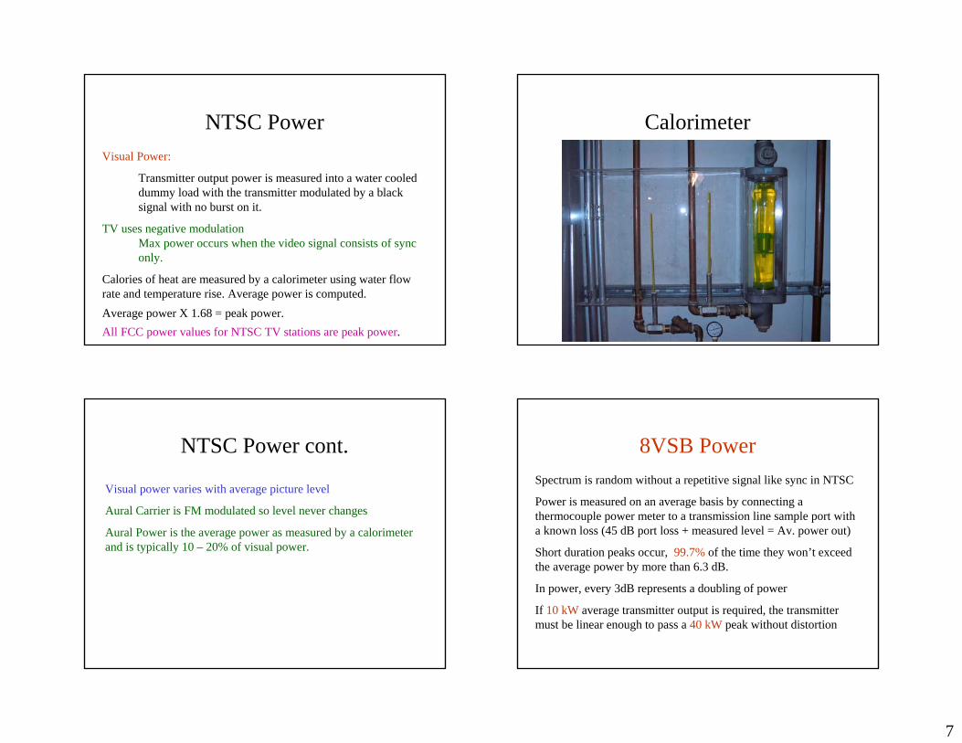
Calories of heat are measured by a calorimeter using water flow rate and temperature rise. Average power is computed.Average power X 1.68 = peak power.All FCC power values for NTSC TV stations are peak power.
Calorimeter
NTSC Power cont.
Visual power varies with average picture level
Aural Carrier is FM modulated so level never changes
Aural Power is the average power as measured by a calorimeter and is typically 10 – 20% of visual power.
8VSB PowerSpectrum is random without a repetitive signal like sync in NTSC
Power is measured on an average basis by connecting a thermocouple power meter to a transmission line sample port witha known loss (45 dB port loss + measured level = Av. power out)
Short duration peaks occur, 99.7% of the time they won’t exceed the average power by more than 6.3 dB.
In power, every 3dB represents a doubling of power
If 10 kW average transmitter output is required, the transmitter must be linear enough to pass a 40 kW peak without distortion

8
Driver and IOT
• Ratings much be conservative to provide headroom and avoid non-linear operation
• Common problem is trying to get by without sufficient reserve in driver
• Running driver near edge requires changing corrections as driver distortion will vary with ambient temp
HP Power Meter
8VSB SpectrumNo signal carriersCentered in channelRolloff slopes 618.881 kHz from channel bottom and channel top.3dB Pilot Carrier 309.411 kHz above lower channel edge3 dB Nyquist bandwidth of 5.381119 MHz
Channel SpectrumChannel spectrum looks like a haystack unless averaging is used on a spectrum analyzer
With averaging it looks similar to the diagram with skirts of 36 dB or greater at the channel edges (If there’s no adjacent channel)
Due to gain bandwidth distortions when using short spans on a spectrum analyzer (such as 10 MHz) the pilot amplitude will be greatly exaggerated.

9
HP Vector Signal Analyzer Spectrum using Analyzer averaging function
Pilot is actually much lower. It appears large because of resolution bandwidth of Spectrum Analyzer. Using a greater span causes it to appear smaller
Dirty Little SecretsAll digital TV (cable too) is actually analog.
Digital information is encoded as a vector with a certain magnitude and a certain angle.
Errors occur due to non-linear effects that produce magnitude and phase errors.
All digital TV transmissions must model the buffer in the receiver to avoid buffer underflow or overflow. Null packets are sent to avoid underflow
• A bit is a 0 or 1• Two adjacent bits result in 4 states: 00, 01,
10, 11 that can be represented by 4 analog voltage levels
• Adding an additional bit for error correction and concealment makes 8 levels 000, 001, 010, 011, 100, 101, 110, 111
Binary Numbers & Symbols

10
8 Voltages and their Binary Values
• 8 octal numbers are represented by the following voltages:
• 000 -7 100 +1• 001 -5 101 +3• 010 -3 110 +5• 011 -1 111 +7
DTV Constellation
• 60 1 2 3 4 5 6 7
-7 -5 -3 -1 1 3 5 7
000 = 0001 = 1010 = 2011 = 3100 = 4101 = 5110 = 6111 = 7
Q ValuesThe I (in-phase) values are set at +/- 1, 3, 5, 7
Why do the Q (quadrature) values vary?
The Q values are used to shape the channel edges to make them drop off sharply.
Observed spectrum edges are at least 36 dB down and may be > 40 dB. The actual FCC spec is tighter but it is defined in such a way that it can’t be measured using a practical instrument.
Eye Pattern
7531-1-3-5-7

11
8VSB SymbolsChannel 3 dB bandwidth: 5.381119 MHz
A sine wave of that frequency would have double that many half cycles.
That’s the limit of how many symbols can be sent
Symbol rate = 5.381119 X 2 = 10.762238 MSym/sec
Each symbol represents a 3 bit number
Bits/sec = 10.762238 X 3 = 32.286714 MBits/sec
Payload net of overhead = 28.9 MBits/sec
Payload, net of error correction = 2/3 X 28.9 = 19.267 MHz
8VSB FeaturesData is randomized
Reed-Solomon coding added to protect from burst noise
Data is interleaved (spread out) to avoid errors from impulse noise
Trellis coding – randomizes data to produce a flat spectrum
Root raised cosine filtering (avoids having ringing from prior symbols interfere with the current symbol)
Equalizer training signal – 511 symbols of pseudo-random data
Types of Data Packets
Some data packets define what is contained in the transport stream, carry clock information, EAS messages, Closed Captioning, etc. PID, PCR, PAT, PMT
Video packets for HD or multiple SD channels
Associated Audio packetsPSIP – Program and System Information Protocol
Defines relationship of DTV channel to ATV channel Program guide for all programs carried in signal Text and other data
DATA Broadcasting – replaces null packets with data such as news, internet pages, messaging etc.

12
Signal Transport
Uncompressed HD occupies 600 MHZ BW Progressive scan is 2XMezzanine compressions fits HD into DS3 channel BW (45 MB/S)Blown back up, it can be switched with local HD before ATSC encoding
Insert commercials, add ID bugs etc.
Mezz vs ATSC
• NHK provided free HD pool feed of 2000 political conventions
• We used mezz feed done for participating($) stations – looked OK
• PBS did ATSC encoding at site and uplinked – It was much better
Local Xport
• Analog SD video and audio flat rate of $1.5K/mo anywhere in local area
• DS3 – 4 miles to Sutro $6K/mo on contract• PUC sets price based on number of POTS
circuits 45 MHZ can carry
HD Channel Usage1 HD broadcast channel using 19.39 MHz + datacasting using available null packets
1 HD Broadcast channel with a bandwidth of 11 to 15 MHz + 1 SD channel => 3.5 MHz bandwidth + datacasting using available null packets
5 to 6 SD broadcast channels using a statmux to allocate bandwidth dynamically + datacasting using available null packets
FCC requires that one channel be open but permits the others to be conditional access
See www.atsc.org Standard A70 for Conditional Access details

13
Off Air Signal Check using Triveni Streamscope (Courtesy Triveni Digital) Packet Content – per Triveni
Audio Buffer per TriveniTransmitter Block Diagram

14
Zenith 8VSB Exciter MPEG Packets / Data SegmentsStandard MPEG transport packet = 187 bytes
Add 20 bytes of Reed Solomon parity code = 207 bytes
207 bytes X 8 = 1656 bits
Trellis coding – For every 2 bits of data a third bit is added for error correction
1656 bits X 3/2 = 2484 bits
1 8VSB symbol = 3 bits
2484 bits / 3 = 828 symbols
1 8VSB data segment = 828 symbols + 4 symbols of segment sync = 832 symbols per segment
Segment Diagram Data Frames2 data fields = 1 data frame
313 segments = 1 data field
626 segments = 1 data frame
First segment in each data field carries field sync information and the 511 symbol training signal used by the receiver equalizer
10,766,080 symbols/ sec // 832 symbols/segment =
12940 segments/ sec
12940 segments/sec // 626 segments/frame = 20.67 frames / sec

15
Field Sync PSIP ProblemsPSIP – Program and System Information Protocol
Channel on cable won’t be the same as over the air channel
Information re DTV and ATV channel #s will have to be corrected to conform to cable channel #s.
Cable system may convey PSIP information using an out of band channel for data (OOB). PSIP information will have to be decodedand muxed into that stream.
HD Pass-thru Interlace & Progressive ScanInterlace – Every other line in the picture is scanned. TV Field 1 -( 1,3,5,7…) then the lines in between are scanned for TV Field 2 (2,4,6,8…) Actually field 1 ends in the middle of a line and field 2 starts in the middle of a line
Progressive – All the lines are scanned in sequence
Interlace advantage – Less bandwidth is required to send half of the information and then the other half. Motion information is updated in each field.
Progressive advantage – Picture appears sharper because there are no interlace errors in the picture but the frame rate must be as high as the field rate in interlace (approx 60 frames/sec)

16
3:2 Pull downFilm runs at 24 frames/sec and video at 30 frames/sec
In conventional TV, a special projector called a telecine is used. It alternates between holding film frames for 3 TV fields or 2 TV fields. After 24 frames of film, 60 TV fields or 30 frames have been televised.
3 X 12 frames + 2 X 12 frames = 36 + 24 = 60 TV fields = 30 F
This creates a jerky motion distortion known as “judder”
In DTV, 24 frame film can be broadcast directly and displayed. No need to use a telecine projector. 24 frames is one of the normalDTV modes and 24 frame video cameras and recorders are being used to make TV shows and movies.
EAS
Acquiring the SignalKnown reception problems:
Strong reflections may cause multiple notches and distortions in the signal that render it unusable
When a ghost is cleaner that the direct signal, the direct signal will appear as a leading ghost to the receiver. Early receivers had a limited window for accommodating leading ghosts.
Dynamic multipath distortion may prevent the receiver from locking to the signal. Training signal inadequate for short duration interference and interference with phase rotation.
Receivers near a transmitter site may need a 6 – 10 dB pad in the antenna lead to prevent overload. Overload can be from other nearby signals saturating the receiver front end.
Strategic Errors
• Broadcasters are the only ones required to use 8VSB– No impact on cable or DBS– After Feb 17, 2009 broadcast NTSC ceases
only for over-the-air broadcasts• No upgrade path to newer coding schemes
– NTSC lasted > 50 years– MPEG 2 – 5 years, 10 years?

17
COFDM
Ideal for cell type scheme using many low powered repeaters as done in Europe
Not good for the US single central site scheme due to power required for comparable coverage
Interference during transition phase would have been excessive.
Would have worked if we had kissed off the single site transmitter scheme and paid some broadcasters to just go away
Channel BW
• In Europe 8 mhz broadcast channels permit enough COFDM carriers to make it advantageous.
• Number of carriers possible in a U.S. 6 mhzchannel make COFDM a wash with 8VSB
A failed scheme goes on
– Broadcasting from one central point is a failed delivery scheme
– Cable + DBS penetration is 85% of households– No requirement for cable to carry anything but
“free” unconditional access channel– Research and testing has been done on single
frequency networks but I doubt many will be realized.
USDTV
• Cable that isn’t cable– In markets with no significant terrain problems such as
Las Vegas, Salt Lake City, Fresno, Albuquerque etc. multiple encoded SD channels are used to create a cable-like system
– 4 or 5 stations provide 4 channels carrying popular cable programs plus 1 providing their main program to USDTV
– DTV receiver with decoder is provided at a discount to local basic cable monthly fee

18
Future Trends
– A great deal of money is no longer on the table for broadcasters.
– Alternate forms of delivery including non-realtime will drain the best demographic segments as they give up on TV viewing
– As 20 years ago the studios realized more money selling movie tapes than they did from theatrical releases so it soon may be with popular TV programs.
Cable Off-Air HD ReceiversScientific Atlanta SA 6237 Freq Agile 8VSB Receiver
Receives off-air 8VSB Ch 2 - 69
Outputs: SMPTE 310M
DVD-SPI LVDS
( Mpeg-2 synchronous parallel interface)
DVB-ASI (asynchronous serial interface)
10 MHz reference for DVB-ASI
www.motorola.comClick Cable Operators then white papers
Download: “High-Definition Television Over Cable”
Download: “Acronyms”
Motorola cont.

19
Motorola cont. 2 Terayon Cherrypicker
Selects and modifies MPEG 2 transport streams
Terayon cont. Terayon cont 2

20
Terayon Grooming Terayon Ad Insertion
OpenCable Receiver Consumer set contains set-top box digital functions in a Terminal Host Device. Will probably be bi-directional
DOCSIS Modem is built into the receiver
Conditional Access card from cable company defines what can be viewed from cable
HD signals are output on a IEEE-1394 connection to an HD recorder. (Firewire is Apple tm ilink is Sony tm)
IEEE-1394 rate is 400 Mbits/sec with 1.2gigabits proposed
Consumer HD Receivers$10 to $14 per pound for flat screen 34” CRT Sets. Sets lack IEEE 1394 interface and OpenCable electronics with conditional access card
Panasonic CT34WX52 172 lb
Toshiba 34HHX82 176 lb
Philips 34PW9818 176.5 lb
Sony KV34XBR800 201 lb

21
Anticipated Sea ChangeStandard Definition Digital Cable and DBS are somewhat better than VHS tape in picture quality
Okay for small CRTs but really soft on a big screen. Portions ofimage breaking up into checkerboards will be more visible.
The difference between an HD broadcast and compressed SD will bepronounced.
Not a problem as long as there are few HD viewers
But, Consumer Electronics wants to make big bucks from HD whether or not Broadcasters, Cable, or DBS do anything
Merry Xmas - Blue-Ray Disc
Blue-violet laser DVD 27 gigabytes of payload in a single layer2 hrs HD playing time & 13 hrs SD playing timeThe Usual Suspects:Hitachi, LG Electronics, Matsushita Electric
Industrial Co., Pioneer, Royal Philips Electronics, Samsung Electronics, Sharp Corporation, Sony Corporation and Thomson Multimedia.
Coming to the stores by 2003 holiday seasonComing in the future: multilayer 1 terabyte discs
Thank You