atlas: the enterprise cartography tool - ceur-ws.orgceur-ws.org/vol-2229/paper2.pdf · atlas is an...
TRANSCRIPT

Atlas: the Enterprise Cartography Tool
Pedro Sousa12, Ricardo Leal2, and Andre Sampaio2
1 Instituto Superior Tecnico, Av. Rovisco Pais, 1, 1049-001 Lisboa, Portugal,[email protected],
2 Link Consulting SA, Av. Duque de Avila 23, 1000 Lisboa, [email protected]
Abstract. The need to maintain architectural representations of enter-prises is an indescribable fact nowadays given their constant need evolve.However, despite the large number of Enterprise Architecture tools avail-able, enterprises are unable to maintain architectural models updated,given the effort it entails. Atlas is an Enterprise Architecture tool con-ceived to reduce the effort needed to keep architectural models updated,in enterprises where changes are constant and design occurs in a de-centralized, distributed and asynchronous process using multiple designtools. Atlas uses Enterprise Cartography as the approach paradigm to beable to generate architectural views automatically from the models andinformation gathered from multiple sources, with a time bar allowing aseamless navigation in time, from past to future models.
Key words: Enterprise Cartography, EA, Enterprise Architecture, Ar-chitecture Visualization, Architecture tools
1 Introduction
The need to maintain explicit knowledge of the architecture of enterprises is anindisputable fact nowadays given their constant need to evolve. Either for thepurpose of enterprise governance, engineering, compliance or maintenance, ar-chitectural representations are an enterprise asset that must be governed[1]. Byexplicit knowledge we consider both the existence of models of the EnterpriseArchitecture, hereafter EA, kept in some repository as well as the capability topresent graphical representations of the enterprise artifacts and their dependen-cies, also referred as architectural views[2, 3], here after referred as EA views forspace reasons.
We refer to enterprises and not to organizations since the first term hasa wider scope according to the the Open Group definition were ”enterprise isany set of organizations that have a common set of goals”[2], and the approachpresented here applies to both. An example of an enterprise is the PortugueseNational Health System1, that includes more than one hundred health organiza-tions.
1 Servio Nacional de Sade: https://www.sns.gov.pt

2 Pedro Sousa et al.
We also consider a distinction between enterprise transformation and evo-lution, the difference being that the former is mostly related with top levelrestructure and the later is related with the optimization of current state ofaffairs[4]. Despite the differences, they both require EA as input data and theyboth causes changes in enterprise, thus likely induces changes in the EA. Hereafter we use the term change initiatives to refer to both transformation andevolution initiatives. Since change initiatives are temporary, unique and a pur-poseful activity, they correspond to the concept of projects as defined in theproject community[5].
Stefan[6] presents a list of 28 EA application scenarios and the correspondingliterature sources, making clear importance of knowing the EA for enterprisemaintenance, planning and evolution. In its simpler and basic from, informationabout EA boils down to the list of enterprise artifacts and their dependencies.Given the variability and quality of existing EA tools and their representationcapabilities[7], one could argue that enterprises could easily create and maintainan EA repository where all models are kept updated so that core enterpriseactivities could benefit from such information[6].
However, based on our experience of nearly two decades in organizationsfrom various countries and industry sectors, we found that this is not the case.On the contrary, enterprises are far from being able to create and maintain anEA repository updated, given the effort that such endeavor would entail. Webelieve that a significant part of such extra effort results from the followingorganizational aspects:
– Enterprise evolution uses multiple ”Enterprise Architecture” tools. Enterpriseevolution uses multiple tools for EA, being office tools commonly used ones.Most of the times such tools are not integrated and do not provide coherentinformation. For example, when the board of director of a company, actingas an architect designing the company, decides to create a new departmentthey will not go to an EA tool to model the new department. Most likely, thedecision will appear the board meeting minutes (probably an office document)a few weeks or months before the intended date. If the organization structureis modeled in some EA tool, effort is required to update it in conformity withthis new design. The person that performs such update in the EA tool is notdesigning but merely updating the model and its architectural representations.
– Enterprise evolution is mostly a distributed and asynchronous process. Enter-prise evolution is planned and designed by different units in an asynchronousand distributed process, involving many actors and many dimensions of con-cerns without formal mechanisms of communication between the different de-signers. For example, when a director decides to make changes in their de-partment, it probably will conduct meetings with other departments to checkfor possible dependencies and impacts. Directors of other departments cando the same for their departments. Despite the number of face-to-face meet-ings, there is no design process established so that the knowledge gathered insuch meetings is consolidated and shared across the enterprise, so that designactually uses coherent and updated information.

Atlas: the Enterprise Cartography Tool 3
In such context, one can envisage the huge effort required to update themodels in the EA tools used. The fastest the enterprise changes, the more effortis required to keep such models updated. When enterprises are already faced withlack of resources for the day to day projects, they are not willing to allocate effortto keep enterprise models updated.
But the problem is actually more complex because enterprises models are alsoa moving target. In fact enterprises need models that refer to different points intime, namely:
AS-WAS models. These models represent the enterprises past state of affairs, in-cluding not only the past architecture but also the plans of change initiativesof the past. They are most useful for auditing and accountability purposessince they can hold justifications for the decisions taken in the past. Forexample, the decision took in the past to acquire development capacities onsome technology could be sustained on the plans of a change initiative tobuild new products using that technology, regardless the fact of that changewas actually put forward or dismissed.
AS-IS models. These models represent the current enterprise. AS-IS models arerequired for current operations and for reacting to events.
TO-BE models. These models represent the future enterprise, and are criticalfor planning the next change initiatives, as recognized both by EA[8, 9] andproject management[10, 11] communities. In fact, to plan a project thatwill start in 6 months, you need to know how the enterprise will be whenthe project starts, not what it is today, as many changes can come in themeantime.
Naturally, AS-WAS models are just the old AS-IS and do not pose anychallenge. But AS-IS and TO-BE models are real challenges, since they must betake into consideration the multiple ongoing change initiatives. This difficulty hasa substantial impact on the ability to plan change initiatives and, consequently,has an impact on the costs, time and risks of achieving their expected outcomes[8,11].
So, the focus of our research has been in finding a low effort method thatallows enterprise to have updated AS-WAS, AS-IS and TO-BE models and EAviews. To keep architectural models and views updated, one needs to address twomain issues: (i) how to gather information about the changes in the enterprisemodels and views and, (ii) how to update the architectural models and viewsbased on the gathered information. Again, our experience in actual companieshas shown us directions for such questions.
– Gather information about the changes. Our finding is was that, in general, itis easier to gather information about what people are currently doing thanabout what they did in the past. Since what people are doing today is whatmost likely will be enterprise TO-BE, this finding means that it is easier toknow the expected TO-BE than the AS-IS of the enterprise. So, since TO-BEmodels will become AS-IS and AS-WAS, this finding tell us that the focusshould be target to TO-BE models.

4 Pedro Sousa et al.
– Update EA views. Our finding is that hand-draw EA views will likely remainobsolete much longer than generated views. Hand-draw models requires plac-ing symbols in a drawing canvas, where aesthetic aspects are one key concernand time consuming factor. Therefore, to keep such views updated, one needsboth to update the contents as well as the aesthetic aspects. So, this findingtell us to avoid hand-draw view and support only automatic generated viewsfrom gathered models (information).
Atlas2 was designed to explore the findings presented above. It is an EA toolconceived to reduce the effort needed to keep EA views updated in enterprisesdesigned in a decentralized, distributed and asynchronous process using multipledesign tools. In Atlas, EA views are generated automatically and have a timebar allowing a seamless navigation in time, from past to future state of each EAview. Information about changes is gathered by the observation of the plans ofongoing change initiatives.
This approach was first presented in[12], initial implementation was describedin [13, 14], and results from first projects were presented in[15, 16]. The termEnterprise Cartography was coined in[17]. In the next section we present theconcept of Enterprise Cartography, and then we present relevant aspects of theAtlas tool in supporting the above ideas.
2 Enterprise Cartography
Simply put, EC is the process of abstracting, collecting, structuring and rep-resenting architectural artifacts and their relations from the observation of en-terprise reality. The expression ”enterprise reality” refers to the present stateof the enterprise. Traditionally, the observation of this reality is a subjectiveperception of an observer, and consequently it is probable that there are differ-ent actors that perceive different realities of the same enterprise. However, aswe propose and will become clear along the text, the perception of the presentstate of the enterprise (the reality) is sustained on relevant facts captured in logsand models, and represented through artifacts based on previously defined andagreed upon models.
We refer to ”architectural artifacts” as the enterprise’s observable elementswhose inter-dependencies and intra-dependencies express the architecture of theenterprise. Naturally, different institutions may consider various sets of artifactsas part of their architecture. To abstract, structure and represent the architecturerelated artifacts, one needs the whole set of knowledge and concepts impliedin architecture visualization and representation. For example, the concepts ofsemiotic triangle[18, 19], the model of architecture description presented in ISOIEEE 1471[3] and a symbolic notation, such as the one used in ArchiMate[20],are concepts necessary to the production of EA views.
Ongoing change initiatives and their plans are an essential part of enterprisereality because they define the near future TO-BE of the enterprise if no further
2 www.linkconsulting.com/atlas
Atlas: the Enterprise Cartography Tool 5
decisions are taken that might have an impact on them. This is a fundamentalconcept that we call emerging AS-IS, which we define as the state of the enter-prise after successful completion of ongoing change initiatives. This correspondsto the inertia of a body; if no contrary action is taken, inertia determines thebody future position and speed. Similarly, if no opposite actions are done, on-going initiatives determine the future of the institution and thus the TO-BE ofmodels and architecture.
Given that in today enterprises, change initiatives are omnipresent, the con-cept of Emerging AS-IS is not only an essential capacity for the planning ofnew change initiatives, but also for the monitoring of the enactments of ongoingchange initiatives. When driving a car the faster the car is moving, the fartherahead one should focus our eyes to match the longer time and distance contextwithin which we need to steer it. Likewise, when steering an enterprise, the fasterthe enterprise is changing, the more important is to know the emerging AS-IS,as time flows.
Enterprise cartography is a purely descriptive perspective, since it does notexplicitly incorporate the purposeful design of the new enterprise artifacts, asone expects in EA. Such a difference is also evident in the definitions of thearchitect and cartographer roles. According to the IEEE Standard Glossary ofSoftware Engineering Terminology[21], the term architect is defined as ”Theperson, team, or organization responsible for designing systems architecture”,and in the Merriam-Webster dictionary[22], the term cartographer is defined asthe person who makes maps. So, an architect is essentially a person that designsand shapes intended changes to the architecture of the present enterprise reality,while a cartographer is essentially a person that aims at representing reality asit happens, including such changes as they are occurring.
2.1 Enterprise Cartography Principles
Principle 1: Change initiatives are enterprise artifacts.A change initiative is an enterprise artifact. This statement is in line withmost architecture guidelines such as the Work Package concept in bothTOGAF[2] and ArchiMate[20]. However, we go further and also state thattheir plans can be observed as part of the enterprise AS-IS models. We as-sume that change initiatives have plans because they purposefully aim atsome desire goals and therefore should have plans to achieve them. Further-more, these plans and goals includes TO-BE models of the enterprise .
Principle 2: Changes in the set of productive artifacts are planned ones.This principle states that artifacts do not become productive or non-productive randomly, but only as a result of change initiative. Since changeinitiatives are also enterprise artifacts (principle 1), an artifact becomes pro-ductive or non-productive only by the action of another productive artifact(the change initiative). Notice that the assumption that ongoing change ini-tiatives are productive artifacts, is sustained by the purposefulness aspect ofthe change initiative, by which the enterprise becomes more valuable afterthe purposeful changes than before.
6 Pedro Sousa et al.
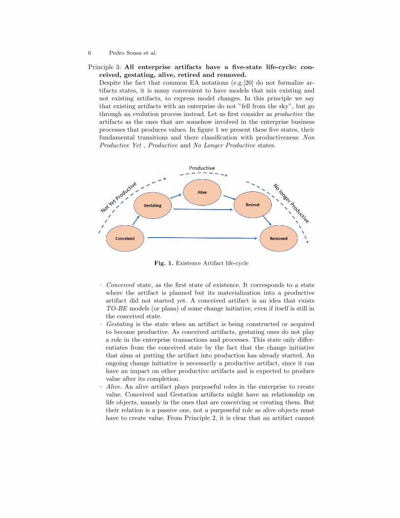
Principle 3: All enterprise artifacts have a five-state life-cycle: con-ceived, gestating, alive, retired and removed.Despite the fact that common EA notations (e.g.[20] do not formalize ar-tifacts states, it is many convenient to have models that mix existing andnot existing artifacts, to express model changes. In this principle we saythat existing artifacts with an enterprise do not ”fell from the sky”, but gothrough an evolution process instead. Let us first consider as productive theartifacts as the ones that are somehow involved in the enterprise businessprocesses that produces values. In figure 1 we present these five states, theirfundamental transitions and there classification with productiveness: NonProductive Yet , Productive and No Longer Productive states.
Fig. 1. Existence Artifact life-cycle
– Conceived state, as the first state of existence. It corresponds to a statewhere the artifact is planned but its materialization into a productiveartifact did not started yet. A conceived artifact is an idea that existsTO-BE models (or plans) of some change initiative, even if itself is still inthe conceived state.
– Gestating is the state when an artifact is being constructed or acquiredto become productive. As conceived artifacts, gestating ones do not playa role in the enterprise transactions and processes. This state only differ-entiates from the conceived state by the fact that the change initiativethat aims at putting the artifact into production has already started. Anongoing change initiative is necessarily a productive artifact, since it canhave an impact on other productive artifacts and is expected to producevalue after its completion.
– Alive. An alive artifact plays purposeful roles in the enterprise to createvalue. Conceived and Gestation artifacts might have an relationship onlife objects, namely in the ones that are conceiving or creating them. Buttheir relation is a passive one, not a purposeful role as alive objects musthave to create value. From Principle 2, it is clear that an artifact cannot
Atlas: the Enterprise Cartography Tool 7
be brought into existence as alive; it always exists first as conceived beforebeing alive.Notice that in this paper we only consider Alive as the only productivestate. However, one can consider other productive states, such as for ex-ample the Deprecated state. However, it is not relevant for the purpose ofthis paper and we continue with the case of alive as the only productivestate.
– Retired3. is when an alive artifact no longer plays a role in the enterprisetransactions and processes to create value. As in the conceived and gesta-tion states, a Retired artifact may still have an impact on alive artifacts.In fact, even if it does not create behavior or value to the enterprise, itmay be the target of several housekeeping activities that are necessaryafter being dead.The dead state can be achieved directly after gestating state, withoutbecoming alive. An artifact planned to become alive by a given changeinitiative might never be alive either because the initiative was canceledor because it simply changed plans and decided to no longer put thatartifact into production.
– Removed. Represents the post-Retired state where the artifact has no im-pact in the remaining artifacts. A removed artifact is unable to interactwith alive enterprise artifacts. An artifact can move from conception di-rectly to removal when it never materialized in a gestation, meaning thatit never went beyond an idea.
Principle 4: The TO-BE state precedes the AS-IS state.This principle states that productive artifacts in the AS-IS model existedbefore in the TO-BE models of some changing initiative. Furthermore, suchmodels were part of the enterprise observed AS-IS at some point in timeprior to the current time.
Principle 5: The emerging AS-IS can be inferred by observing the AS-IS of an enterprise.The emerging AS-IS state differs from the AS-IS state by the artifactsplanned to be brought into production/retirement by ongoing change ini-tiatives. Since ongoing initiatives are alive artifacts, their plans (TO-BEmodels) are in the scope of the cartographer observations of the enterprisereality.Therefore, one can foresee the set of productive artifacts at some point intime in the future by consolidating the AS-IS with the TO-BE models ofthe ongoing change initiative whose completion date precedes the desiredmoment in time[12]. This can be stated as:
P (tm) = P (t0) ∪NY P (CItn) \NLP (CItn)∀t0 ≤ tn ≤ tm (1)
Where P (t) represents Productive artifacts at time t, NY P (CIt) and NLP (CIt)represents respectively Not Yet Productive and Not Longer Productive arti-facts in plans of Change initiatives that produces results at time t.
3 In previous publications the Retired stated was named as Dead.

8 Pedro Sousa et al.
3 Atlas Overview
Altas is a web based EA tool providing all functionality one could expect fromsuch a tool. It allows the full configuration of the meta model, i.e. the classes andreferences types whose instances are used to express models of the organization.Users can also configure in and out data both in format as well in contents forintegration with other tools and systems.
Atlas supports custom configured user interfaces. Given the wide scope of us-age of EA tools within organizations, it will likely be used by employees withoutbasic modeling concepts. So, besides allowing the configuration of elements inAtlas default interfaces (e.g, tabs in object edition properties), it allows users toconfigure specific forms, where users only see the desired properties, even if theyare from different objects. Atlas also provides analytic elements such as charts,dashboards and EA views that we called blueprints.
Atlas also supports the configuration of behavior associated with EA views,validation rules, state propagation between objects in the repository, amongothers. Such behavior can be stated both in queries and rules that run directlyon the selected repository as well as in jobs and batch’s that run on a dedicatedsandboxes.
Fig. 2. Atlas collecting AS-IS and TO-BE models and produce AS-WAS, AS-IS andTO-BE EA views
We now focus the description of how Atlas supports enterprise cartography.A typical scenario is presented in figure 2 where information from several sources,including office tools, is processed and feeds the generation of AS-WAS, AS-ISand TO-BE EA views and analysis. In this scenario, enterprise artifacts andtheir relationships exist in multiples sources, and each source will likely have itsown meta model. Furthermore, information in each source may be related withthe past, present or future of EA.

Atlas: the Enterprise Cartography Tool 9
3.1 Model transformation
Model transformation occurs whenever data flows between sources with differentmeta models, as is the case when Atlas gathers information from other sources,and has been a relevant topic in software development and integration[23].Among the different technologies to handle model transformation[23], in At-las we adopted a two step approach, each with its own technology. The first stepdeals with the format transformation and is based on XSLT[24] which is verycommon and convenient for processing XML files. The second step deals withthe actual model transformation, and uses a high level type-based rules thatoperates on types, instances and relationships.
Consider the case where one wants to import a BPMN[25] model and thatData Stores must be imported as Applications in the Atlas repository. To con-figure such rule, one assigns a batch to the desired source or file extension andthen defines three jobs. The first job is configured with the XSLT script thatconverts the BPMN tool format into Atlas XML format. The second job is con-figured with text file script with the transformation rules, that transforms thesource model and objects into Atlas model and objects. Finally the third jobimports the transformed objects into the Atlas repository. In the example given,the transformation rules script is a ”rename data type Data Store to Applica-tion”. The names of the Data Stores in the BPMN model are matched againstApplications in the Atlas repository, and unmatched Data Stores will yield thecreation of new Applications, as discussed in the next section.
If several batchs are assigned to the same source or file extension, the useris requested to select one to upload the file. This is a very useful feature sincewithin the same enterprise, different teams or departments may use the samenotation differently and different rules might be required.
Another rather important aspect is to be able to perform different a behaviourin case of the imported artifacts match with objects that already exist in theAtlas repository or if new objects were created during the importation. Therules allows the importation behaviour to be dependent of any state in the Atlasrepository, but the match for existing objects is done solely on the object names,as discussed next.
3.2 Object Names
In the scenario presented in figure 2 one needs to establish a mechanism tomatch objects existing in different sources that correspond to the same enterpriseartifact. In other words, one needs an identification mechanism valid throughoutthe different sources to match imported objects against the ones that alreadyexist in the Atlas repository.
The use of 128 bits Object Identifiers (OIDs, also known as UUIDs) ensuresuniqueness for most practical purposes even when generated by different andindependent tools. However, these system-generated OIDs are not useful in thescenario presented in figure 2, since the same enterprise artifact would haveobjects with a different OID in each source.

10 Pedro Sousa et al.
Change is also a factor against the use of OIDs. Consider that a processmodeling tool holds a model of the sales process in which the CRM applicationis used to inquire the status of the client payments. Later, the process changesand instead of using the application CRM, it now uses the application ERP forthe same purpose. This change can be done simply by change the applicationname, from CRM to ERP. However, in this case, the name has change but theOID in the process modeling tool is the same, despite the enterprise artifacthas changed. This leads to a situation where the same object now referrers toa different enterprise artifacts, breaking the existing biding between OIDs andenterprise artifacts even in the context a single tool.
User defined object names can easy the task of matching objects betweensources, if object names correspond to the names of the artifacts have in theenterprise. However, in most cases, object names are used defined and normallyare not unique, since uniqueness is assured by OIDs. In Atlas, we took a differ-ent approach where identification and denotation is established by user definedobject names[26] and OIDs are not disclosed to user, except for audit traces.This approach implies that, from the user perspective, objects of the same classcannot have the same name.
In practice this can be a strong restriction in large enterprises where onecould expect to have several organizations with different business processes oractors with the same name. For example, in the case of Portuguese NationalHealth System, one could expect to have Actors with the same name in differenthospitals. To support this scenario, users can define composite object names,by selecting object properties to be used for its identification, as primary keysin relational databases. In this case, the name of the object could be definedby both hospital and Actor names.Notice that users can change the name ofobjects, given that they are object editable properties.
Despite the fact that in most situations users deal with a flat object namespace, full object names are unique URLs composed as follows:
serverURL/RepositoryName/ClassName/ArtifactNameField N. ...ArtifactNameField 0.
The concatenation of the fields ArtifactNameField N to ArtifactNameField 0must be unique within the objects of the same ClassName. All fiels but the lastare optional (i.e can be null), except the last one ( ArtifactNameField 0 ) thatcannot be null.
3.3 Object State
In Atlas, object state is defined as a set of properties values, whose types are userdefined. A time bar in the object edition interface allows users to visit propertiespast states, up to the time of its creation. Basic types as Numeric, Text, RichText, Hyperlink, Boolean are available. Users must define their own referencetypes for reference properties
Object properties do not change type (structure) over time, this means that,for example, a numeric property cannot not become a reference property. How-ever, object sate, as a collection of properties, can change structure over time

Atlas: the Enterprise Cartography Tool 11
since properties may be added or removed from its class over time as discussedin the next section. Therefore, objects of the same class can have an entirelydifferent set of properties.
References properties are assured to be either null or to refer to one or moreobjects. There are no dangling references, since reference value assignment trig-gers object creation and object deletions nullify references. In Atlas, object arecreated when their names are registered thus, by assigning a new name (value)to a reference properties a new object is created with that name. Such createdobject has no state yet, only a name.
By default reference properties have no state associated besides besides thename of the denoted object. However, in some situations it is very convenientto add properties to references. This is done by binding a class with a referenceproperty, whose structure becomes the structure of the class. Any class definedin the meta model can be bound to a reference property, and the same class canbe bounded to different reference properties.
3.4 Meta model Co-Evolution
As described earlier, classes also change over time whenever users remove or addproperties. By moving back the time bar in the class edition interface, one cansee the class properties at any point in time, up to time the class was created.Property creation and removal does not affect the state of the objects in therepository. If a property is deleted from a class at a given time, it will no longerbe visible in the object’s structure after that time, however, as soon as the timebar goes back in time the deleted property will appear in object state historywith the corresponding values.
Besides adding and removing properties, Atlas also provides support for com-plex operations in meta-model and is able to propagate the necessary changesto objects in the repository. For example, the Property to Class meta modeloperation promotes a textual property to a reference property to a class createdfrom the original text property. An example could be promoting the Home Ad-dress text property of a Client class into a reference property to a new classHome Address, so that clients with the same address could share the same ob-ject. A meta-model evolution primitive catalog, with primitives such as FlattenHierarchy, Merge Class, Split Class, Property to Class, Class to Property, amongothers[27, 28] is available.
These type of changes in the meta model requires the changes on existingobjects in the repository according with the changes made to the correspondingclasses. To support such operations, Atlas is able to inform the impact that eachchange has in the objects existing in the repository and execute them if thenecessary actions can be performed automatically [29, 30, 31].
3.5 Object life-cycles
Object life-cycle is defined over a set of object user defined properties of type,one for each life-cycle state. Users can define several life-cycles for the same class.
12 Pedro Sousa et al.
For example, for the application artifact, one may define the existence life-cycleand technical quality life-cycle. For each life-cycle, users can define any numberof states, and assign a color to each one, so that objects are shaded with thecolor corresponding to the state of the object at the selected date in the EAview.
As explained in the next section, Atlas has specific built-in behavior asso-ciated with the visualization of object life-cycles that requires uses to classifythem as Not Yet Productive, Productive or No Longer Productive. Users definelife-cycle states in order and some sates may be declared as Productive. Thestates prior to the first Productive state are considered Not Yet Productive andstates after the last Productive state are considered No longer Productive.
3.6 Visualizing AS-WAS, AS-IS and TO-BE EA views
In atlas, EA graphical views are generated on-the-fly given its unique name, inthe form of an URL as serverURL/RepositoryName/EAViewName?arguments.This means that, by placing hyperlinks to EA views, users that access and in-teract with them outside the Atlas tool in documents or in other web interfaces.
EA views are defined in a simple XML language, where one can define con-tainers that can hold others containers or a content query whose result set de-termines the objects that will be displayed inside that container. Containers canbe set in a hierarchy and grow and shrink within user defined limits accordingto the number of objects of the query result set. Objects can also be containers,whenever one wants other results sets to be presented inside.
Once generated, EA views are interactive interfaces where users can navigatein time, run predefined analyses, jump to another EA views and drag objectsbetween containers, triggering containers out-query and in-query to do the nec-essary state update associated with the object movement between containers.For example, dragging an object of actor John from a container representingSales Unit to a container representing Legal Unit will trigger the correspondingout-query on the Sales Unit and in-query on the Legal Unit containers with theactor John as argument.
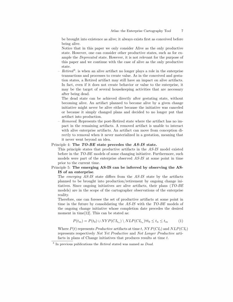
In what concerns time navigation capability of EA views, in Atlas each andevery EA view is as a movie, where one can see its contents from the minimumto the maximum date found among all objects that encompass the EA view. Aspresented in figure 3, the time bar has two handlers, one on the left for the lowerdate and another in the right for the upper date.
Fig. 3. EA view Time bar
By moving the time bar handlers back and forward one can see the architec-ture view in the selected time. The visualization can occur either in Absolute
Atlas: the Enterprise Cartography Tool 13
Mode or Gap Mode. In the Absolute Mode, the view presents the contents thatcorresponds to the time selected. Two options can be selected:
– Default: Only productive objects at selected time are presented. Symbols arepresented in their default color.
– life-cycle: All objects are presented, but their symbols is shaded with the life-cycle colors. For example, a typical life-cycle configuration is to shade in greythe artifacts that are Not Yet Productive at the selected time, and to shade inred the objects that are No Longer Productive objects at the selected time.
In Gap Mode, the Visualize the view presents the gap between two pointsin time Ti and Tf , by shade the objects symbols according to the difference oflife-cycle state of each object on the selected Times Ti and Tf [32]. In this mode,artifacts are marked as:
– Introduced. An artifact is considered to be introduced between Ti and Tf ifit is Not Yet Productive at Ti but it is Productive at Tf .
– Withdraw. An artifact is considered to be withdraw between Ti and Tf if itis productive in Ti and is No Longer Productive in Tf .
– Changed. An artifact is considered to be changed between Ti and Tf if it isProductive in both Ti and Tf and if at least one artifact with which it hasa reference to as been introduced or removed between Ti and Tf . The userscan select the depth of the graph traversal analysis and for each step, thereferences to be used.
In the next three figures (4 to 6) we present the same EA view with differentoptions and dates of visualization. The first figure presents the architecture at10/05/2018 in absolute mode with life-cycle option on. The container in themiddle show the components of application Account Management App, thatconsume services in the container on the middle left, that in turn and providedby applications in the leftmost container. Likewise, the Account ManagementApp components provide the services presented in the middle right containerthat are consumed by the applications in the rightmost container. Bellow, onepresents the data objects used in each service. Objects shaded in grey or red are,respectively, Not Yet Productive or No Longer Productive at 10/05/2018.
By switching the life-cycle mode off, the shaded objects (both introducedand Withdraw) disappear from the EA view, leaving only the objects that were,are or will be4 productive at 10/05/2018. The corresponding figure is not shownsince it can be easily perceived.
By moving the left part of the time handle back in time to 05/04/2014, thevisualization switches to Gap mode between 05/04/2014 and 10/05/2018, aspresented in figure 6, where introduced objects appear in green and withdrawones appear in red.
Next, we set the life-cycle mode on again, mixing the Gap and life-cyclemodes, as presented in figure 5, where the evolving objects are shaded in two
4 Both the dates used in this example (05/04/2014 and 10/05/2018) could refer tothe past, present of future.

14 Pedro Sousa et al.
halves: On the left side, with the color associated with the life-cycle state at thefirst date (05/04/2014) and, on the right side, with the color associated with thelife-cycle state at the second date (10/05/2018).
Fig. 4. EA view at 10/05/2018 with object life-cycle
Fig. 5. EA view Gap between 05/04/2014 and 10/05/2018
The time bar presented in these three figures show four markers, excludingthe extremes, revealing the dates of change in that EA view. These dates cor-respond to object life-cycle evolution but can also be traced back to the changeinitiatives that have produced such evaluations, as explained next.

Atlas: the Enterprise Cartography Tool 15
Fig. 6. EA view Gap between 05/04/2014 and 10/05/2018 with life-cycle
3.7 Change Initiatives
According to cartography principles, enterprise artifacts evolve in its life-cycleas a result of some planned change initiatives. In Atlas, used defined class maybe a change initiative class, and more than one change initiative class may exist.For example, one may define the Project class as change initiative of Technologyartifacts, and the Work-Package class for business changing initiatives.
For simplicity, Atlas assume that change initiatives produce the expected re-sults at the very end, meaning on the date they become non-productive. To modela situation where a change initiative produces results before its non productivedate, one must use a hierarchy of change initiatives, where the top one has achild for each result it has to produce with the non productive date matchingthe desired date.
The relationship between change initiatives and object life-cycle states is akey factor to simplify the update and management of enterprise artifacts life-cycle dates. For example, if a project, that is replacing one application by a newone delays one month, this delay should be reflected in the life-cycle of bothapplications, specifically in the old application retirement date and in the newapplication alive date.
In Atlas this relationship is established by a user defined reference propertydeclared at the class level, either at the change initiative class or at the objectclass. For example, in a typical scenario, one may define the Alive List and theRetired List reference properties in a project class to identify the objects thatwill become alive and retired. Such relationships allow the update of objects life-cycle according to the life-cycle of the corresponding change initiative. In thisscenario is, the kickoff and completion of change initiatives yields the followingbehavior:
– When the change initiative starts: propagate the current date to both changethe initiative alive date and gestation date of objects in the Alive List.

16 Pedro Sousa et al.
– When the conclusion date of a change initiative has a new forecast: propagatethe forecast date to the retired date of the change initiative, to the alive dateof objects in the Alive List and to the retired date of objects in the RetiredList.
Such state propagation is not a built-in behaviour in Atlas and must be con-figured in state propagation rules associated to object life-cycle. This providesmore flexibility and independence regarding to the actual life-cycle states theuser can define for each class. A more advanced usage of these dependencies andrules is to perform repository coherency validation analysis, in particular basedon the time dependent relationships[33].
4 Conclusion
The goal we pursuit with Atlas and Enterprise Cartography is to be minimizethe effort required to provide updated and trustful EA views, in enterpriseswhere their architecture is the result of many local architectures, each designedwith different drivers and optimization factors. So far, we can say that achievingthis goal is fundamentally dependent on the enterprise’s ability to provide goodenough plans and descriptions of their change initiatives. Using the scenariopresented in previous section, this boils down to having the Alive List and theRetired List of change initiatives completed. In such case the effort required tokeep AS-IS and TO-BE EA views updated is non-existent in practical terms.
Since the Alive List and the Retired List of a given change initiative represent,for all practical matters, what needs to be done in that change initiative andwhat impact it has in the enterprise, they are also related with the cost, timeand risk of that change initiative. In other words, the can conclude that the morethe enterprise is willing to manage cost, time and risk of their change initiatives,the more likely will be the success of our proposal.
However, we also conclude that we still miss a clear and easy mapping be-tween project management practices and standards with the EA artifacts andtheir life-cycle evolution to easy the completeness of change initiatives. For ex-ample, if a project intends to create and deploy a new application service on agiven date on a given infrastructure, then these facts should be stated somehowin the project plan and deliverables, so that they can be subsequently importedto complete the Alive List and the Retired List of the corresponding changeinitiative.
The Project Management Body of Knowledge[5] defines the work-breakdownstructure as a ”A hierarchical decomposition of the total scope of work to becarried out by the project team to accomplish the project objectives and cre-ate the required deliverable.” Since enterprise artifacts life-cycle is by defini-tion a result (deliverable) of a project, they are likely to appear in projectwork-breakdown structure. We are currently working in the establishment ofa more formal mapping between enterprise artifact life-cycle and project work-breakdown structure[11]. The idea is to integrate Atlas with the project man-agement tools used in the enterprise and capture the information needed for

Atlas: the Enterprise Cartography Tool 17
completion of change initiatives and make enterprise cartography a more simpleand accessible capability to enterprises.
Acknowledgements
This research was supported by the Link Consultings project IT-Atlas (n 11419),under the IAPMEI, 2020 Portuguese PO CI Operational Program.
References
1. Hoogervorst J. A. (2009) ”Enterprise governance and enterprise engineering”.Springer.
2. The Open Group. (2011). ”TOGAF Version 9.1”. (10th ed.). Zaltbommel, theNetherlands, Van Haren Publishing.
3. 1471-2000 - IEEE Recommended Practice for Architectural Description of Software-Intensive System. Replaced by ISO/IEC 42010.
4. Proper, H.A., Winter, R., Aier, S., de Kinderen, S. (Editors)(2017) ”ArchitecturalCoordination of Enterprise Transformation”, Springer.
5. Project Management Institute (2017). ”A Guide to the Project Management Bodyof Knowledge” (PMBOK Guide)Sixth Edition Newtown Square, Pa, September 22.
6. Bischoff, S., (2017). ”The Need for a Use Perspective on Architectural Coordination”pp 87-98, in Proper, H.A., Winter, R., Aier, S., de Kinderen, S. (Editors)(2017)”Architectural Coordination of Enterprise Transformation”, Springer.
7. Roth, S., Zec, M., Matthes, F., (2014): Enterprise Architecture Visualization ToolSurvey 2014. Technical Report. Sebis, Technische Universit at Munchen.
8. Ugwu, K. (2017). ”Understanding the complementary relationship between enter-prise architecture and project management”. in Architecture and Governance Mag-azine (online version, accessed in May 2018).
9. Labusch, N., (2017). ”Information Requirements for Enterprise Transformation”pp 111-117, in Proper, H.A., Winter, R., Aier, S., de Kinderen, S. (Editors)(2017)”Architectural Coordination of Enterprise Transformation”, Springer.
10. Schomburg, K., Barker, T. (2011). ”Integrating the IT PMO with enterprise archi-tecture for better government”. In proceedings of PMI Global Congress 2011NorthAmerica, Dallas, TX. Newtown Square, PA: Project Management Institute.
11. Bernardo, M., Sousa, P., (2018) ”Portfolio Management. Enabling a dynamic Or-ganization IS representation”. 22nd International Congress on Project Managementand Engineering (ICPME 2018), Madrid, Spain.
12. Sousa, P., Lima, J., Sampaio, A., Pereira, C., (2009). ”An Approach for Creatingand Managing Enterprise Blueprints: A case for IT Blueprints”. The 21st Inter-national Conference on Advanced Information Systems, Lecture Notes in BusinessInformation Processing, vol. 34, pp. 70–84, Springer-Verlag, The Netherlands .
13. Sampaio, A. (2010) An Approach for Creating and Managing EnterpriseBlueprints. Master Thesis in University of Lisbon - fenix.tecnico.ulisboa.pt
14. Leal, R., (2010) Navigation model between Architectural Views: ”An approach for anew paradigm: Navigation in Enterprise Architecture”, Master Thesis in Universityof Lisbon - fenix.tecnico.ulisboa.pt

18 Pedro Sousa et al.
15. Sousa P., Gabriel R., Tadao G., Carvalho R., Sousa P.M., Sampaio A. (2011). ”En-terprise Transformation: The Serasa Experian Case.” In: Harmsen F., GrahlmannK., Proper E. (eds) Practice-Driven Research on Enterprise Transformation. PRET2011. Lecture Notes in Business Information Processing, vol 89. Springer, Berlin.
16. Sousa P., Sampaio, A. Leal, R. (2014). ”A case for a Living Enterprise Architec-ture in a Private Bank”, In proceedings of the 8th Workshop on Transformation &Engineering of Enterprises (TEE 2014), July, Geneva.
17. Tribolet, J; Sousa, P.; and Caetano, A. (2014). The Role of Enterprise Governanceand Cartography in Enterprise Engineering. Enterprise Modelling and InformationSystems Architectures, 9 (1): 38-49.
18. Morris, C.W., (1938). ”Foundation of the Theory of Signs”, International Ency-clopedia of Unified Science, Vol. 1, No. 2.
19. Dietz, J. (2006). ”Enterprise Ontology - Theory and Methodology”, Springer.20. The Open Group. (2015). ”ArchiMate 2.1 Specification”. Van Haren Publishing,
Zaltbommel, www.vanharen.net.21. IEEE. (2010). ”Systems and software engineering – Vocabulary”, in
ISO/IEC/IEEE 24765:2010(E) , pp.1-418, Dec. 1522. https://www.merriam-webster.com, accessed in September 2017.23. Tratt, L. (2205) ”Model transformations and tool integration”, Software and Sys-
tems Modeling, May 2005, Volume 4, Issue 2, pp 112122.24. W3C (1999) XSL Transformations (XSLT).25. Grosskopf, Decker and Weske (2009). ”The Process: Business Process Modeling
using BPMN”. Meghan Kiffer Press.26. Sousa, P., Rito, A., Alves Marques, J. (1995). ”Object Identifiers and Identity : A
Naming Issue”, In IEEE Proceedings of the 4th International Workshop on ObjectOrientation in Operating Systems, Lund, Sweden.
27. Wachsmuth, G. (2007). Metamodel adaptation and model co-adaptation. In TheEuropean Conference on Object-Oriented Programming 2007 (ECOOP) (Vol. 4609,pp. 600624).
28. Cicchetti, A., Di Ruscio, D., Eramo, R., and Pierantonio, A. (2008). Automatingco-evolution in modeldriven engineering, in Proceedings of the 12th IEEE Inter-national Enterprise Distributed Object Computing Conference, IEEE ComputerSociety, pp. 222231.
29. Silva, N., Ferreira, F., Sousa, P., Mira da Silva, M. (2016). ”Automating the Mi-gration of Enterprise Architecture Models”. In International Journal of InformationSystem Modeling and Design (IJISMD) 7.2 pp 72-90.
30. Silva, N., Mira da Silva, M., Sousa, P., (2018). ”A Tool for Supporting the Co-Evolution of Enterprise Architecture Meta-models and Models”, In 27th Interna-tional Conference on Information Systems Development, August 22-14, Lund, Swe-den.
31. Silva, N., Sousa, P., Mira da Silva, M.(2018).”CO-EVOC: An Enterprise Archi-tecture Model Co-Evolution Operations Catalog”. In 24th Americas Conference onInformation Systems, August 16-18, New Orleans, USA.
32. F.,Carolina, P. Sousa, A. Sampaio. (2016) ”Visualiazacao da Evolucao da Ar-quiteturas Empresariais”, 16 Conferencia Associacao Portuguesa de Sistemas deInformacao (CAPSI), 22 September, Porto.
33. Xavier, A., Vasconcelos, A., Sousa, P. (2017) ”Rules for Validation of Models ofEnterprise Architecture-Rules of Checking and Correction of Temporal Inconsisten-cies among Elements of the Enterprise Architecture”. International Conference onEnterprise Information Systems ,2, 337-344.