atlas pot bearing - arsan kauçuk · atlas pot bearing is used for structures such as bridges and...
TRANSCRIPT

www.arsankaucuk.com.tr
ATLAS POT BEARING
1


1. Pot2. Piston3. Elastomeric Pad4. Sliding Plate5. Stainless Steel Plate 6. PTFE7. Dust Seal8. POM Seal9. Anchor Bolts
4
5
627
83
1
9
POT BEARING WORKING PRINCIPLE
ATLAS Pot Bearing is used for structures such as bridges and viaducts which are exposed to different rotational and displacement effects, and is designed according to EN 1337-5, AASHTO LRFD .
ATLAS POT BEARING
ATLAS Pot Bearings consist of a steel pot, an elastomeric pad in this pot, and a steel piston element that transmits the vertical load and rotational effects of the superstructure on the elastomeric pad to the substructure. The elastomeric pad can safely accommodate rotational effects up to 0.03 radians by a viscous fluid motion in the pot.
The horizontal and vertical forces transferred from superstructure are transferred to the pot by the piston. If required, pot bearings can make free horizontal movements in one direction or in all directions. The horizontal movement is provided by a special PTFE material placed on the piston with low friction and high pressure resistance.
3
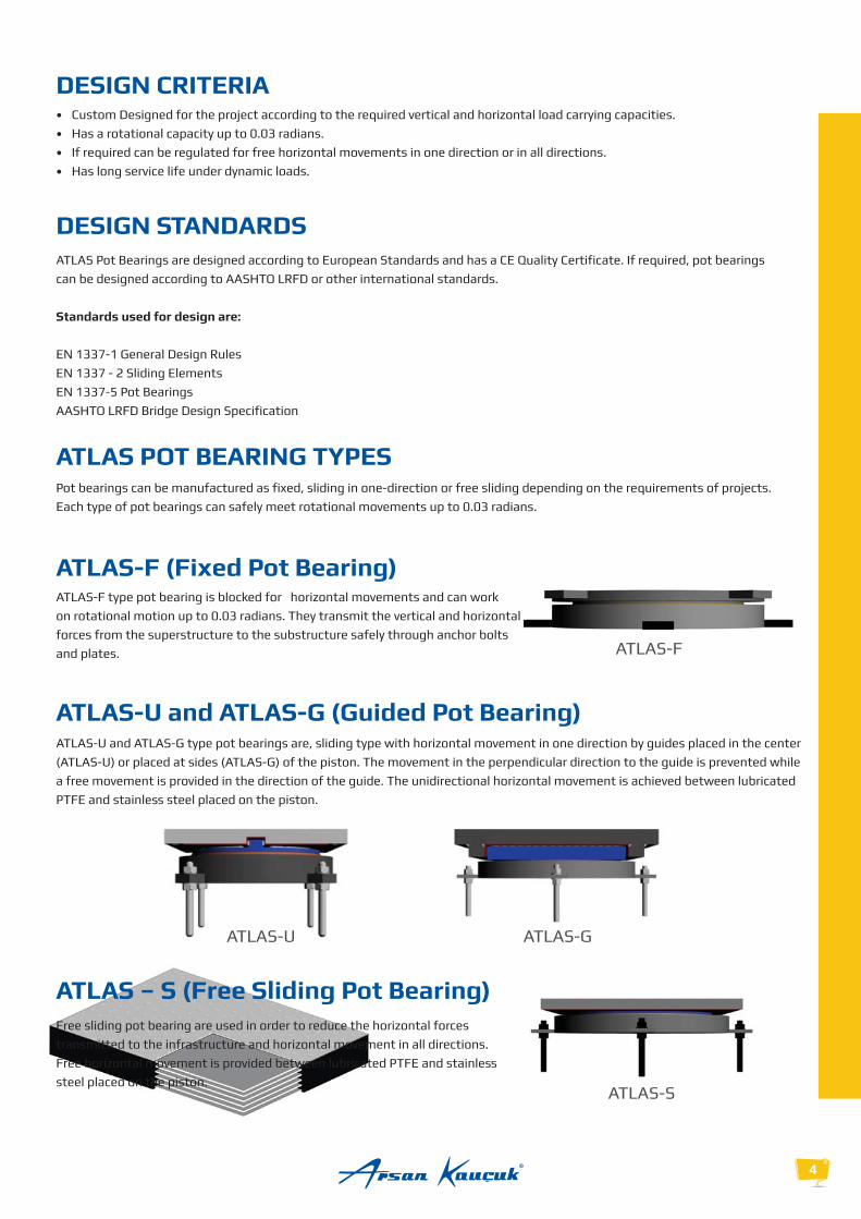
DESIGN STANDARDSATLAS Pot Bearings are designed according to European Standards and has a CE Quality Certificate. If required, pot bearings can be designed according to AASHTO LRFD or other international standards.
Standards used for design are:
EN 1337-1 General Design RulesEN 1337 - 2 Sliding Elements EN 1337-5 Pot BearingsAASHTO LRFD Bridge Design Specification
DESIGN CRITERIA
ATLAS-F
ATLAS-F (Fixed Pot Bearing) ATLAS-F type pot bearing is blocked for horizontal movements and can work on rotational motion up to 0.03 radians. They transmit the vertical and horizontal forces from the superstructure to the substructure safely through anchor bolts and plates.
ATLAS POT BEARING TYPES
Each type of pot bearings can safely meet rotational movements up to 0.03 radians.
4
ATLAS-U and ATLAS-G (Guided Pot Bearing) ATLAS-U and ATLAS-G type pot bearings are, sliding type with horizontal movement in one direction by guides placed in the center (ATLAS-U) or placed at sides (ATLAS-G) of the piston. The movement in the perpendicular direction to the guide is prevented while a free movement is provided in the direction of the guide. The unidirectional horizontal movement is achieved between lubricated PTFE and stainless steel placed on the piston.
ATLAS – S (Free Sliding Pot Bearing) Free sliding pot bearing are used in order to reduce the horizontal forces transmitted to the infrastructure and horizontal movement in all directions. Free horizontal movement is provided between lubricated PTFE and stainless steel placed on the piston.
ATLAS-S
ATLAS-U ATLAS-G

Elastomeric PadElastomeric pad is produced from natural rubber (NR) according to the criteria specified in
EN 1337-5. It is placed in the pot under high pressure and temperature in accordance with the
standard and dimensions determined by the design. Arsan produces highest quality elastomeric
pad by its rubber over 60 years.
Structural SteelCompliant to EN10025-2 standard, 3.1 Certified, S355 quality structural steel. According to the
qualities. The structural steel for required size of the pot bearing is machined by modern
CNC machines in ARSAN plants.
PTFE (Polytetrafluoroethylene)Standard PTFE has a characteristic compressive strength of 90 MPa. In sliding type of pot bearings,
surfaces that come in contact with stainless steel play a key role due to the high pressure resistance
and low friction properties. They are used with 3.2 certified oil channels or straight in accordance
with EN1337-2 standard.
Stainless SteelStainless steel is a material that contacts with PTFE directly and provides smooth and low-friction
sliding action in sliding types of pot bearings.
5
POT BEARING COMPONENTSATLAS Pot Bearings consist of elastomeric pad, sliding material, stainless steel, connection plates and anchorage elements
NOTES: These components may vary according to project requirements.
Sliding Plate
Piston
Pot
Elastomeric Pad
Lubricant
Anchorage Bolts
S355
S355
S355
NR
Components Material
10.9
Silicone

6
P : Axial Load D : Piston Diameter
Vx,y : Design Shear Force H : Pot Bearing Height ATLAS-FFixed Pot Bearing
ATLAS-SFree Sliding Pot Bearing
P : Axial Load V1 : Longitudinal Displacement Capacity
C : Top Plate Long Edge Length
ATLAS -S1 - 50/20
ATLAS -S2 - 50/20
ATLAS -S3 - 50/20
ATLAS -S4 - 50/20
ATLAS -S5 - 50/20
ATLAS -S6 - 50/2
ATLAS -S7 - 50/20
ATLAS -S8 - 50/20
ATLAS -S9 - 50/20
ATLAS -S10 - 50/20
ATLAS -S12 - 50/20
ATLAS -S14 - 50/20
ATLAS -S16 - 50/20
ATLAS -S18 - 50/20
ATLAS -S20 - 50/20
ATLAS -S25 - 50/20
ATLAS -S30 - 50/20
ATLAS -S40 - 50/20
ATLAS -S50 - 50/20
ATLAS -S75 - 50/20
1000
2000
3000
4000
5000
6000
7000
8000
9000
10000
12000
14000
16000
18000
20000
25000
30000
40000
50000
75000
0,010
0,010
0,010
0,010
0,010
0,010
0,010
0,010
0,010
0,010
0,010
0,010
0,010
0,010
0,010
0,010
0,010
0,010
0,010
0,010
210
280
340
380
430
460
490
520
550
580
630
680
720
760
800
900
960
1150
1250
1550
370
450
500
540
575
610
640
670
700
750
800
850
920
960
1000
1100
1200
1350
1460
1750
71
82
91
98
101
107
112
113
121
128
143
151
164,5
178,5
186,5
210,5
240,5
266
325
406,5
25
50
75
100
120
150
175
190
230
275
370
455
560
680
800
1125
1550
2300
3450
6450
310
380
440
485
535
575
625
650
675
730
790
850
930
975
1025
1150
1250
1405
1550
1850
± 50
± 50
± 50
± 50
± 50
± 50
± 50
± 50
± 50
± 50
± 50
± 50
± 50
± 50
± 50
± 50
± 50
± 50
± 50
± 50
P(kN) (rad)
B(mm)
L(mm)
C(mm)
V1(mm)
± 20
± 20
± 20
± 20
± 20
± 20
± 20
± 20
± 20
± 20
± 20
± 20
± 20
± 20
± 20
± 20
± 20
± 20
± 20
± 20
V2(mm)
H(mm)
W(kg)
ATLAS - F1
ATLAS - F2
ATLAS - F3
ATLAS - F4
ATLAS - F5
ATLAS - F6
ATLAS - F7
ATLAS - F8
ATLAS - F9
ATLAS - F10
ATLAS - F12
ATLAS - F14
ATLAS - F16
ATLAS - F18
ATLAS - F20
ATLAS - F25
ATLAS - F30
ATLAS - F40
ATLAS - F50
ATLAS - F75
0,010
0,010
0,010
0,010
0,010
0,010
0,010
0,010
0,010
0,010
0,010
0,010
0,010
0,010
0,010
0,010
0,010
0,010
0,010
0,010
141
283
424
566
707
849
990
1131
1273
1414
1697
1980
2263
2546
2828
3536
4243
5657
7071
10607
210
300
365
425
480
525
565
610
640
680
740
810
860
910
960
1100
1180
1440
1625
1850
52
58
64
71
76
85
92
98
101
107
116
124
133
141
146
164
182
200
233
279
310
400
485
575
630
700
750
790
800
850
925
1000
1050
1125
1150
1300
1375
1675
1875
2075
15
30
45
65
85
115
150
180
205
240
310
400
480
575
655
1000
1250
2000
3050
4650
P(kN)
Vx,y(kN) (rad)
B(mm)
D(mm)
H(mm)
W(kg)
1000
2000
3000
4000
5000
6000
7000
8000
9000
10000
12000
14000
16000
18000
20000
25000
30000
40000
50000
75000

ATLAS-GGuided Pot Bearing
P : Axial Load C : Top Plate Long Edge Length
Vx,y : Design Shear Force V1 : Longitudinal Displacement Capacity
L : Top Plate Short Edge Length
ATLAS - G1 - 50
ATLAS - G2 - 50
ATLAS - G3- 50
ATLAS - G4 - 50
ATLAS - G5 - 50
ATLAS - G6 - 50
ATLAS - G7 - 50
ATLAS - G8 - 50
ATLAS - G9 - 50
ATLAS - G10 - 50
ATLAS - G12 - 50
ATLAS - G14 - 50
ATLAS - G16 - 50
ATLAS - G18 - 50
ATLAS - G20 - 50
ATLAS - G25 - 50
ATLAS - G30 - 50
ATLAS - G40 - 50
ATLAS - G50 - 50
ATLAS - G75 - 50
1000
2000
3000
4000
5000
6000
7000
8000
9000
10000
12000
14000
16000
18000
20000
25000
30000
40000
50000
75000
0,010
0,010
0,010
0,010
0,010
0,010
0,010
0,010
0,010
0,010
0,010
0,010
0,010
0,010
0,010
0,010
0,010
0,010
0,010
0,010
315
365
405
460
495
530
570
600
630
660
730
770
810
860
900
990
1080
1265
1440
1710
425
475
535
600
635
680
720
750
760
800
880
910
950
1020
1030
1140
1190
1400
1570
1820
86
92
98
111
117
133
139
148
157
163
164
194
208
212
235
259
297
324
337
432
50
70
100
140
170
235
275
330
380
450
550
740
890
1020
1270
1720
2310
3560
4690
8470
375
430
500
580
625
685
735
775
800
840
925
975
1025
1100
1150
1275
1350
1625
1825
2100
86
92
98
111
117
133
139
148
157
163
164
194
208
212
235
259
297
324
337
432
141
283
424
566
707
849
990
1131
1273
1414
1697
1980
2263
2546
2828
3536
4243
5657
7071
10607
P(kN)
Vx,y(kN) (rad)
B(mm)
L(mm)
C(mm)
V1(mm)
H(mm)
W(kg)
ATLAS - U1 - 50
ATLAS - U2 - 50
ATLAS - U3- 50
ATLAS - U4 - 50
ATLAS - U5 - 50
ATLAS - U6 - 50
ATLAS - U7 - 50
ATLAS - U8 - 50
ATLAS - U9 - 50
ATLAS - U10 - 50
ATLAS - U12 - 50
ATLAS - U14 - 50
ATLAS - U16 - 50
ATLAS - U18 - 50
ATLAS - U20 - 50
ATLAS - U25 - 50
ATLAS - U30 - 50
ATLAS - U40 - 50
ATLAS - U50 - 50
ATLAS - U75 - 50
1000
2000
3000
4000
5000
6000
7000
8000
9000
10000
12000
14000
16000
18000
20000
25000
30000
40000
50000
75000
0,010
0,010
0,010
0,010
0,010
0,010
0,010
0,010
0,010
0,010
0,010
0,010
0,010
0,010
0,010
0,010
0,010
0,010
0,010
0,010
265
335
385
430
480
525
555
590
625
660
730
785
840
900
960
1065
1150
1400
1600
1840
425
475
535
600
635
680
720
750
760
800
860
910
950
950
1020
1030
1140
1395
1495
1770
100
109
115
123
128
134
144
154
163
170
191
202
218
223
247
275
316
347
424
500
55
90
120
160
200
250
300
360
415
485
665
805
980
1100
1425
1840
2540
4150
6515
10225
375
450
505
580
630
685
735
775
785
835
910
975
1025
1100
1150
1275
1350
1625
1825
2075
± 50
± 50
± 50
± 50
± 50
± 50
± 50
± 50
± 50
± 50
± 50
± 50
± 50
± 50
± 50
± 50
± 50
± 50
± 50
± 50
141
283
424
566
707
849
990
1131
1273
1414
1697
1980
2263
2546
2828
3536
4243
5657
7071
10607
P(kN)
Vx,y(kN) (rad)
B(mm)
L(mm)
C(mm)
V1(mm)
H(mm)
W(kg)
7
P : Axial Load C : Top Plate Long Edge Length
Vx,y : Design Shear Force V1 : Longitudinal Displacement Capacity
L : Top Plate Short Edge Length
ATLAS-UGuided Pot Bearing

CORROSION PROTECTIONIn order to protect pot bearings from environmental effects, corrosion protection measures are defined clearly in EN 1337-9.Steel parts which are exposed to external effects must be protected against corrosion.
Standard corrosion protection is as follows:
Special precaution must be taken to protect surfaces since hard chrome plating is not resistant to chlorine or fluoride in acid solution and may be damaged by airborne particles existing in industrial environments.Additional measures must be taken for protection against electrolytic corrosion at locations where other types of metals are used.
PROTECTION AGAINST DIRTThe sliding surface must be protected against dirt by suitable materials. Such protection materials should be easily removable in the event of inspection. Sliding surfaces should be cleaned before installation. During installation process, greasy surfaces must be protected against dirt.
WARRANTY Pot bearings manufactured by ARSAN are guaranteed for 10 years from delivery date, provided that bearings are transported, tored and installed in accordance with EN standards.
MAINTENANCE AND INSPECTIONMaintenance and inspection of pot bearings must be realized visually at the frequency of structure inspection. Pot bearings should also be inspected after natural disasters such as large-scale accidents and earthquakes which will affect the structure.
According to EN 1337-10 there are two types of inspections to be carried out for pot bearings.
In regular Inspection;
should be examined.
8

9
STORAGEBearings are sent to site as ready for installation and it is recommended to install bearings immediately. If the installation cannot be done immediately, bearings must be stored in a way that they are protected from dust, dirt, impact and other harmful effects.
INSTALLATIONInstallation instruction is sent for each type of bearing that has been delivered to site. In case an exceptional installation method
DISPLACEMENT SCALEDisplacement scale is placed on the sliding type pot bearings showing horizontal displacements.
The main inspection can be done less frequent than regular inspections. During main inspection, examinations carried out at regular inspections must be done more detailed. It is recommended that the first main inspection to be done after 1 year service life of structure.
s m
in
s m
ax

PRODUCT LABELING
CE CERTIFICATE
Each pot bearing has a label on it with technical details of its type, properties and installation details.
ATLAS Pot Bearings are fully compatible with EN standards and have CE certificate approved by MPA Karlsruhe. The CE certificate proves that all requirements of the relevant European Standard are fulfilled during design and production of bearing.
10

www.arsankaucuk.com.tr
Phone: +90 216 365 83 06 (pbx) Fax: +90 216 365 83 16 E-mail: [email protected]