atlas detector upgrade focus on inner detector upgrade 3 this talk •will be somewhat reductionist...
TRANSCRIPT

ATLAS Detector Upgradefocus on Inner Detector
Mitch Newcomerfor the
HEP Instrumentation Group

ATLAS Upgrade 2
HEP Instrumentation Group
Rick Van Berg (lead)Nandor Dressnandt, Paul Keener, Walt Kononenko, Godwin Mayers,
Mitch Newcomer, Mike Reilly and Invaluable student help
With this group we have the good fortune to be able to playa meaningful lead role in several parts of the
ATLAS UpGrade

ATLAS Upgrade 3
This Talk• Will be somewhat reductionist in starting with Silicon and
emerging with an ATLAS Upgrade.• Will not defend the upgrade based on expected Physics.• Will assume some Unfamiliarity with the baseline ATLAS
detector and will review the Inner tracker systems.• Will describe the Novel Next Gen tracking sensors at
the end..
• One hope is to encourage additional interest fromwithin the department in Upgrade Activities especiallyNovel sensors that may play an important role in futuredetector systems either at ATLAS or some futuredetector.

ATLAS Upgrade 4
ATLAS Detector at LHC
• Designed for Luminosity of 1034 p /cm2 /s
• In the first 5 years 700 fb-1 * Integrated Luminosity– Most sensors in the inner tracker have occupancies of up to several
percent @ design luminosity. TRT occupancies are highest.
• First Colliding Beams Spring/Summer 2009
* SLHC Upgrade Plans envision 3000 fb-1

ATLAS Upgrade 5
? Atlas Upgrade ?With first LHC collisions set to occur in 2009 why
consider a super LHC ATLAS detector now?Designing and building the ATLAS detector was a daunting task. It is one of themost complex instruments built by people.
Concept to Reality has taken ~ 15years• By starting now we can take advantage of experienced designers battle hardened
by the realities of producing a working detector system.• Higher luminosity will occur in stages at LHC. A new Linac will increase the
Available beam current, possibly by 2014. A better focusing scheme will intensifythe concentration of protons in the interaction point and a tightning of the lengthof proton bunches is expected to increase the luminosity to 1035 by 2017.
• An obvious strategy is to focus contributions on systems with the highestpriority for replacement as beam luminosity evolves upwards.
• Even at the proposed Luminosity of 1034 p/cm2/s sub-systems within thedetector will need replacement in the first few years of LHC operation.

ATLAS Upgrade 6
Silicon Tracking Detectors
• Ionization Energy 3.6eV• 390 eV/um• Gain ~1• Typical Signal 30,000e• Charge Collection time~30ns• Charge Collection node shape
determines tracking coordinateprecision.
Sensor pitch
Anode
+ -+ -
+ -+ -
Pixels ~ 50um X 400umStrips ~ 50um X 10cm

ATLAS Upgrade 7
The ATLAS Pixel Detector

ATLAS Upgrade 8
ASIC
ASIC
Pixel Sensor
ASICASIC Each ASIC 2800 ch
Pixel Sensor and RO 2800 channel Prototype ~ 2002

ATLAS Upgrade 9
Barrel 67 million Pixels 13 million pixels Discs
6.5KW power @2V10% Radiation Length MaterialUseful to an Exposure of 50MRad

ATLAS Upgrade 10

ATLAS Upgrade 11

ATLAS Upgrade 12
ATLAS Upgrade 13
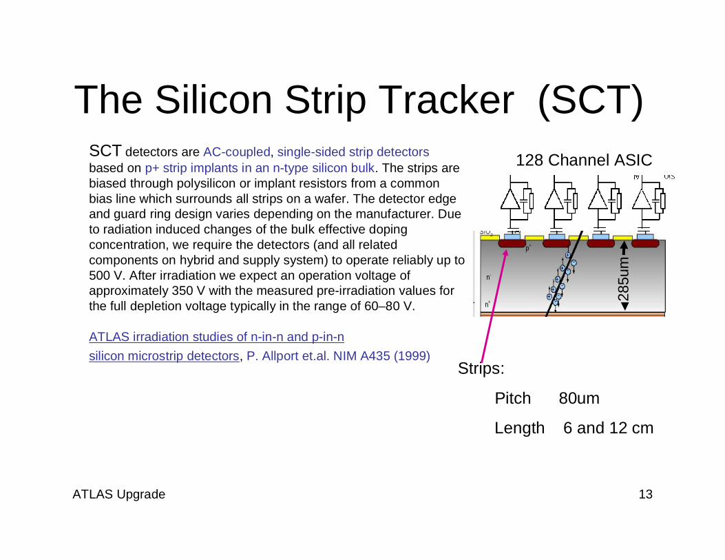
The Silicon Strip Tracker (SCT)SCT detectors are AC-coupled, single-sided strip detectorsbased on p+ strip implants in an n-type silicon bulk. The strips arebiased through polysilicon or implant resistors from a commonbias line which surrounds all strips on a wafer. The detector edgeand guard ring design varies depending on the manufacturer. Dueto radiation induced changes of the bulk effective dopingconcentration, we require the detectors (and all relatedcomponents on hybrid and supply system) to operate reliably up to500 V. After irradiation we expect an operation voltage ofapproximately 350 V with the measured pre-irradiation values forthe full depletion voltage typically in the range of 60–80 V.
ATLAS irradiation studies of n-in-n and p-in-nsilicon microstrip detectors, P. Allport et.al. NIM A435 (1999)
285u
m
128 Channel ASIC
Strips:
Pitch 80um
Length 6 and 12 cm

ATLAS Upgrade 14
Strip Alignment
ASIC

ATLAS Upgrade 15
Silicon Strip Detector Barrel and (Partial) End Caps6.3 million Strips 50um X 6 and 12 cm61m2 Active Silicon 4.5mW per channel

ATLAS Upgrade 16
Dressing CablesFor the SCT Barrel

ATLAS Upgrade 17

ATLAS Upgrade 18
TheTransition Radiation Detector

ATLAS Upgrade 19
TRT Barrel Detector52K axially aligned 1.6M straws
Split anode wires.104K Wire Readouts
@ LHC Design Luminosity operationInner Layers up to 20% occupancyOuter Layers a few %130µm RMS R – information

ATLAS Upgrade 20
TRT End Cap Wheels240K Straws Placed Radially outwards
Straw
align
ment
ReadoutElectronics

ATLAS Upgrade 21
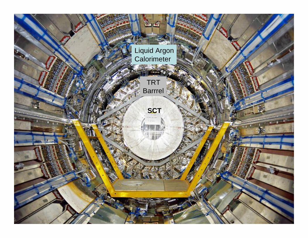
TRT Barrel
SCT

ATLAS Upgrade 22
TRT
SCT
SurfaceAssemblyBuilding

ATLAS Upgrade 23
ATLAS

ATLAS Upgrade 24

ATLAS Upgrade 25
ATLAS Upgrade 26
Liquid ArgonCalorimeter
TRTBarrrel
SCT

ATLAS Upgrade 27
Muon RPC Wheel

ATLAS Upgrade 28
Jack Fowler, DukeWiring the TRT

ATLAS Upgrade 29
Ben Legit MikeHance

ATLAS Upgrade 30
TRTBarrel
SCT

ATLAS Upgrade 31
TRT&
SCT
PixelDetector

ATLAS Upgrade 32

ATLAS Upgrade 33
First Events
September 10, 2008

ATLAS Upgrade 34
September 10, 2008 - A 'splash event' asATLAS detects particles from nearby collisionsfrom the first beams through the LHC

ATLAS Upgrade 35
September 10, 2008 - A 'splash event' as ATLAS detects particles from nearbycollisions from the first beams through the LHC

ATLAS Upgrade 36
September 10,2008 - A'splash event'as ATLASdetectsparticles fromnearbycollisions fromthe first beamsthrough theLHC.

ATLAS Upgrade 37
Upgrades to The ATLAS InnerDetector
Abe Seiden UCSC Report to Joint Oversight Group (JOG) 11/08

ATLAS Upgrade 38
• Ref: LHCC 1/4/2008 – Roland Garoby– http://indico.cern.ch/conferenceDisplay.py?confId=36149
Collimationphase 2
Linac4 + IRupgrade phase 1
Newinjectors + IR
upgradephase 2
Earlyoperation
L= 3 x 1034 cm-2s-1L= 3 x 1034 cm-2s-1
Detector robustness andperformance have to fightfor an higher than the todayBL design luminosity(2x1034) at a smaller radius(3.7 cm instead 5.0 cm)
Detector robustness andperformance have to fightfor an higher than the todayBL design luminosity(2x1034) at a smaller radius(3.7 cm instead 5.0 cm)
LHCC: Peak LuminosityLHCC: Peak Luminosity

ATLAS Upgrade 39
Abe Seiden, UCSC JOG workshop 11/08

ATLAS Upgrade 40
New All Silicon Tracker replaces current pixel, SCT and TRT:- pixels,- short strips (2.5cm)- long strips (10cm)
SLHC Draft Inner Detector Tracker Layout for Planning Purposes

ATLAS Upgrade 41
SLHC predicted occupancyOld assumptions - 230
events/BX…(New estimates~400)
Few comments:• At 4-6 cm pixels layer
should be <300• At 24 cm even short strips
are have > 1% occupancy• At 71 cm long strips have
occupancy > 1%
Pavel Nevski BNL

ATLAS Upgrade 42
SCT LSSCT SSSCT SSSCT SS
PixelPixel - 3d
Det.Radius in cm Dose in kGy5.05 1580012.25 254029.9 76051.4 45043.9 300108 70
NIEL
1014
1015
1016Radiation for 3000 fb-1
• Running up to 3000 fb-1
– Design for 6000 fb-1
– Should take about 6 years (?)à hadron rate for SEE• Detector temperature ~-30oC (minimize damage to Silicon)• Magnetic Field ~2T
SLHC Radiation Environment
Total Dose from Ionizing Particles
Neutron 1MeV Equivalent Dose
Philippe Farthaout TWEPP 2008
(158MRad)
(700KRad)

ATLAS Upgrade 43

ATLAS Upgrade 44
300 fb-1 expected Life time

ATLAS Upgrade 45Abe Seiden, UCSC JOG 11/08

ATLAS Upgrade 46
Long Strip Cylinders (4 meterlength)
Short Strip Cylinders (2 meterlength)
Layer Type Radius[cm]
Phisegmentation
Number ofmodules per half
single sidedstave
Number of 128-chFEIC per half single
sided stave0 Short Strips 38 28 10 4001 Short Strips 49 36 10 4002 Short Strips 60 44 10 4003 Long Strips 75 56 19 1904 Long Strips 95 72 19 190
23614,336270,0801,15257,088327,168
41,877,504Total number of 128-channel FEICs
Total amount of channels
Endcap
Barrel
Total number of staves for the Barrel
Total number of FEIC for the BarrelTotal number of staves for one End-cap
Total number of 128-ch FEIC for the two End-cap
Total number of modules for the Barrel
• Current SCT detector– 4088 modules– 49k 128-channel FEIC– 6.3M channels
Strips Detector in numbersStrips Detector in numbers
Philippe Farthouat (CERN)
ATLAS Upgrade 47
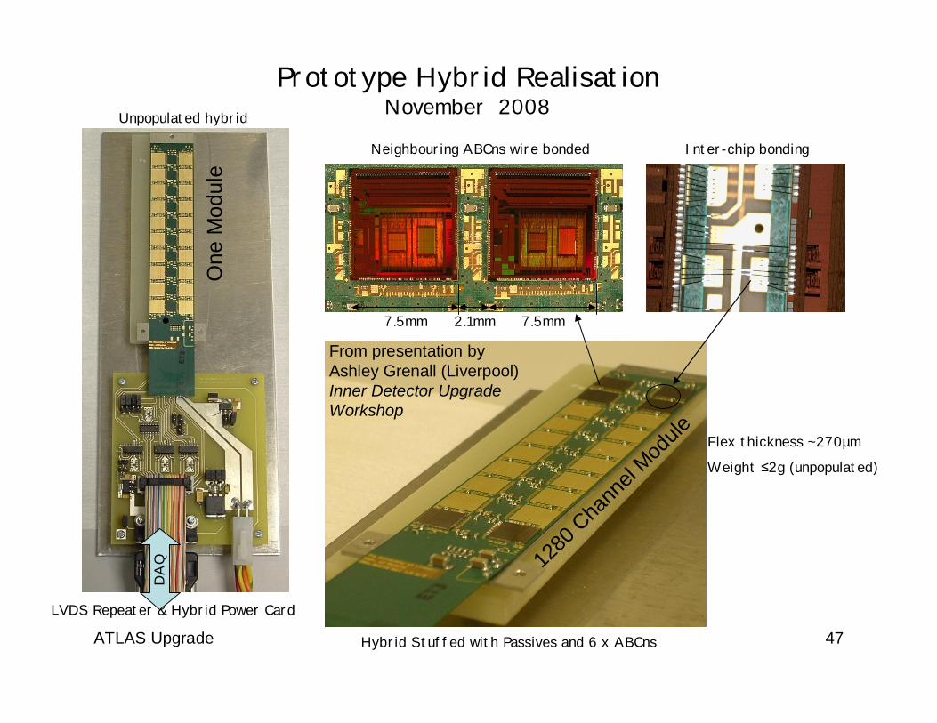
Prototype Hybrid RealisationNovember 2008
LVDS Repeater & Hybrid Power Card
Unpopulated hybrid
DA
Q
Hybrid Stuffed with Passives and 6 x ABCns
Inter-chip bondingNeighbouring ABCns wire bonded
7.5mm 7.5mm2.1mm
Flex thickness ~270µm
Weight 2g (unpopulated)
From presentation byAshley Grenall (Liverpool)Inner Detector UpgradeWorkshop
1280
Cha
nnel
Module
One
Mod
ule

ATLAS Upgrade 48
First Generation Hybrid & ABCn first testsWhat we presently know
• Hybrid connectivity confirmed to be ok• Able to read back correctly thermistor temperature
• Wire bonded up single ABCn as a Master (M0), operating in Legacy mode• Disabled on-board Regulator + Shunt circuits (use external powering/regulation)
• VDDD = 2.5 I = 110mA, VDDA = 2.2V I = 30mA (with clock supplied)• Specification is for a nominal of 96mA and 27mA!
• Clock feed through is enabled, default state for Masters on power-up• 40MHz clock is observed on Ldo outputs
• Send command to disable Clock feed through – 40MHz clock goes away• Chip is responding to commands!
• Send L1 trigger (toggle ABCn between data taking mode and Send_ID mode)• Observe No_Hit data packet and ABCn configuration data packet• ABCn responds to L1 triggers!
M0 M64
M9 M73
M0 Clock Feed Through M73 response to L1 trigger
No-Hit Data Packet
Configuration data packet
40MHz Clock feed through
S8 S72

ATLAS Upgrade 49
SCT Barrel Stave
Bus cable
Hybrids(Modules)
Coolant tube structure
Carbon honeycomb or foam
Carbon fiberfacing
Readout IC’s
Silicon sensors
A conceptual drawing of an SCT barrel stave. Details of powering, cablingcontrol, monitoring and data collection are in early conceptual stages.
24X128X12 per side

ATLAS Upgrade 50
6 x 3 cm, 6 chips wide
10 x 10 cm, 10 chips wide
1 meter, 3 cm strip, 30 segments/side192 Watts (ABCD chip), ~2.4 % Xo + support structure
1.2 meter, 2.5 cm strip, 48 segments/side ~250-300 Watts (@0.25 W/chip)1.7 – 2.4 % Xo + support structure, depends upon coolant and hybrid design
Stave-07
Stave-06
60 cm, 9 cm strip, 6 segments/side
Stave-08
Prototypes and DesignsLBL
Carl Haber LBL

ATLAS Upgrade 51
Serial powering of Staves
0V
SCT Stave
By powering each module in series a cable sized for a single module(2.5A). Can be used to minimize the material in the interaction area.
0V1.2V28.8V 2.4V2.5A
Drawing by Richard Holt (RAL)
2.5A
V24 V …..24 module stave…..

ATLAS Upgrade 52
DC to DC power distribution scheme
Conversion stage 2 (ratio 2)Conversion stage 2 (ratio 2)- Embedded in controller or readout ASIC- Closely same converter for analog and digital (different current, hence different size of switchingtransistors): macros (IP blocks) in same technology
Conversion stage 1 (ratio 4Conversion stage 1 (ratio 4--5.5)5.5)-Vin=10V => high-V technology-Same ASIC development for analog and digital, only feedback resistive bridge is different
10-12V“analog bus” 2.5V
“digital bus” 1.8V
0.9V(core)
2.5V(I/O) 0.9V
(Vdig)1.25V(Vana)
0.9V(Vdig)
1.25V(Vana)
Controller ASIC Readout ASICs
With Efficient DC-DC conversion schemes, voltage and current can be traded offTo lower power cable material required to supply detector mounted ASIC voltages.

ATLAS Upgrade 53
Service bus
TTC, Data
(& DCS)
fibers
PS cable
DCS env. IN
Cooling In
Opto
SC
DCS
interlock
SCHybrid
Module #1 Module #2 Module #10
Cooling Out
(DCS link)
MC
F
E
I
C
s
1600 bits/event100kHz L1 rate
160 Mbits/s
800 bits/event100kHz L1 rate
80 Mbits/s1.6 Gbits/s (20 * 80 Mbits/s)1.6 Gbits/s
160 Mbits/s
3.2 Gbits/s3.2 Gbits/s
Module Data Rates
Philippe Farthouat (CERN)
ATLAS Upgrade 54
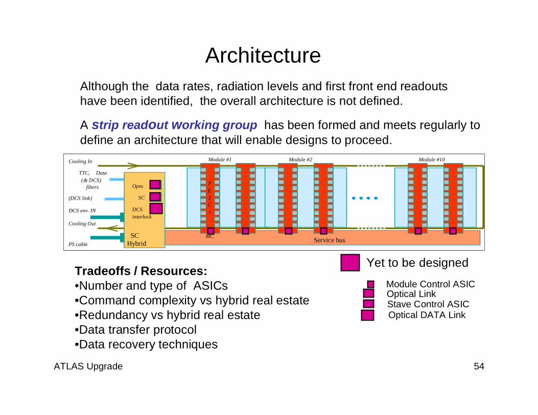
Architecture
Service bus
TTC, Data(& DCS)
fibers
PS cable
DCS env. IN
Cooling In
Opto
SC
DCSinterlock
SCHybrid
Module #1 Module #2 Module #10
Cooling Out
(DCS link)
MC
FEICs
Although the data rates, radiation levels and first front end readoutshave been identified, the overall architecture is not defined.
A strip readout working group has been formed and meets regularly todefine an architecture that will enable designs to proceed.
Tradeoffs / Resources:•Number and type of ASICs•Command complexity vs hybrid real estate•Redundancy vs hybrid real estate•Data transfer protocol•Data recovery techniques
Yet to be designed
Module Control ASICOptical LinkStave Control ASICOptical DATA Link

ATLAS Upgrade 55
Event size for a shortstrips module (40 128-channel FEICs). CurrentATLAS SCT detectorcoding scheme
Mean size ~1600 bits
0 hit 41%1 cluster 34%>1 clusters 21%
Number of hits per FEIC
Simulation for worst case scenario:1035 cm-2 luminosity50 ns BC period (400 overlappingevents per BC)Short Strips
A. Weidberg etal.
A. Weidberg etal.
Short Strip DATA Rate at SLHC

ATLAS Upgrade 56
Fixed Length Data TransmissionFixed size packet forone non-empty ABCn #bits
Start 0 No needChip ID 5 Readout hybrid contains at most 20 chips
Data type 3 Data, register readback, DCS, Test mode, … Notmore than 8 types
Sub-header 12Register address, DCS sub-type, etc and headerfor data. In the later, must contain BCID (8 to 12bits) and L1ID (4 to 8 bits). Max length 12 - 20 bits
CRC 7 7 bits for protecting ChipID, Data type and sub-header (1 error recovery, 2 errors detection)
Pay load 28
Must be large enough so that most of events cantotally fit in that space. If not, a second packetmust be sent which has a large overhead.Simulations show a 21-hit average for 10 ABCn.Size of two isolated hits is 28 bits. Size for threeis 42 bits
Stop 0 No need
Total 55
Many events with ‘0’ occupancy / ASIC see previous slideà Only ASICS with data transmit.

ATLAS Upgrade 57
One possible scheme
• The control of the transmission is very simple as the data are not analysed– Only number of bits transmitted is controlled– Packets from different events can be interleaved
• Note that we are not forced to have the data passing through all the chips;they could share a single bus FEICsàMC and only some arbitrationmechanism is to be implemented
• Size of the Fifos optimised for keeping the level of data loss at the expectedvalue
Event FiFo
Register FiFo
Output Enable FiFos
Flag FiFosXON from next
XON to previous
Data from previous
From internalZS circuitry
From internalRegister read-back
circuitry
Data to next2 lines?
(1 data and one WR)
Arbitration&
Control
Previous chipFiFo

ATLAS Upgrade 58
ASIC Technologies for the Upgrade
• What technology is most appropriate for anext generation detector.– Will it be available in 2014?– Will it offer acceptable low power operation?– Will it be affordable?

ATLAS Upgrade 59
Access To ASIC Technology through CERN Micro Electronics

ATLAS Upgrade 60
CMOS8 RF TechnologyTool Kit
16/9/08 Kloukinas Kostas CERN 60

ATLAS Upgrade 61
Comparison of 250nm and 130nm Technologies
250nm ABCn
Estimate for130nm CMOS version
Total 290mW

ATLAS Upgrade 62
Novel Tracker Technologies
• 3D -- Pixels for the inner detector
• InGrid for a Non Silicon TRT

ATLAS Upgrade 63
3D Silicon TrackingUS Initiative -Sherwood Parker – Hawaii, SLACS. Seidel - New MexicoKevin Einsweiler, Maurice Garcia-Sciveres ( LBL)
Standard Pixel or Strip

ATLAS Upgrade 64
3-D Silicon Tracking• Low depletion fields
Breakdown less likely• Short Drift (50um)
fast signals
Technology complex and still indevelopment in the US andEurope.
-10
-8
-6
-4
-2
0
2
-30 -20 -10 0 10 20 30
0.8 ns rise time pulse to cal. input
trigger channeladjacent channeladjacent channel
puls
e he
ight
(mV)
time (ns)

ATLAS Upgrade 65
GenovaGenova
3d Pixel Sensor for the Inner tracking layers

ATLAS Upgrade 66
Suitable for ATLAS PixelsInnermost layers
Sherwood Parker - Invited Talk NSS 2006
Silicon 3D Tracker

ATLAS Upgrade 67Sherwood Parker - Invited Talk NSS 2006

ATLAS Upgrade 68
Ingrid: Gas Filled Tracking for SLHCOne Gas filled Layer Provides all Track Coordinates
16 mm Ionizationregion
X and Y from Pixel Position
Z from Pixel time
Standard CMOS ASICTechnology with aPassivation Layer
Post ProcessingCreates Grid Structureand mesh

ATLAS Upgrade 69
Drif
t vol
ume
particle
Pixel sensitive plane
Space point and two angles aremeasured:φ − In the pixel planeη − is and angle to the pixel plane
Ingrid is essentially a High Rate mini - Time Projection ChamberThe tracking information it provides can be available within a fewhundred ns making it suitable for Level 1 Trigger input.

ATLAS Upgrade 70
Difference between angle ofthe track for two pseudo
tracks.
Difference betweenreconstructed space points
for two pseudo tracks.
σ= 75 µm σ = 1.7oAngle φ
σ = 0.85o
Reconstructed angle ofthe track.
MC simulation: ThrThr. = 1.5 el,. = 1.5 el, σσtt = 300= 300 µµmm
TTestest BBeam results: comparison with MCeam results: comparison with MC
Exp:σ= 74 µm
Exp:σ = 1.6o
Exp:σ = 0.95o
Anatoli Romaniouk ( ATLAS TRT group)

ATLAS Upgrade 71
INGRIDGas Tracker

ATLAS Upgrade 72
InGrid Gas Tracker

ATLAS Upgrade 73
Conclusions• A huge piece of work lies ahead and there is room and
need for motivated participants.• Although the exact schedule and magnitude of the
upgrade is uncertain the need to upgrade will persist asbeam intensity evolves over the next few years.
This talk has only covered the Inner Detector at ATLASseveral additional sub-systems are seriously working onupgrade plans over a more relaxed time frame. Inaddition to what is discussed here, we are making andplanning contributions to the Liquid Argon and MDTupgrade efforts.