atlas central solenoid - kekatlas.kek.jp/solenoid/2001/cern-20011205.pdf · atlas central solenoid...
TRANSCRIPT

1
DraftDraftWorking List to be done at CERN for
ATLAS Central Solenoid
Originated, Dec. 4, 2001
Revised, Dec.5, 2001
Akira Yamamoto (KEK)

2
General Working List
• Works in Bldg. 180:– CS system delivered and acceptance test made,
– Chimney and prox. cryogenics placed and pre-tested,
– CS assembled into LAr cryostat and General Test made,
• Works in Pit 1:– Chimney and prox. cryogenics installed
– LAr+CS installed into ATAS detector system,
– General test together with LAr calorimeter.

3
Plan at CERN
2001 9 Central Solenoid delivered,
10 ~ Chimney and proximity cryogenics assembly in 180,
2002 6 Test of chimney and proximity cryogenics,
2003 6 Installation of CS into LAr cryostat
10 General test of LAr system with Central Solenoid
2004 Installation of chimney and LAr/CS in the pit.
?? General test in the pit.

4
Works in Bldg. 180
• Delivery– Unloaded, placed, and acceptance check made,
• Proximity cryogenics test– Cryogenics hardware placement and connection,– PLC for cryogenics established,– Power supply ( 10 kA, ??V),– MCS and MSS,
• Installation of CS into LAr crostat– Co-work with CERN/ATLAS/LAr group
• General test of CS with Prox. Cryogenics– Test items to be determined.
• Preparation for movement– Disassembly of Chimney, CD and valve unit

5
General Guide Line forWork Responsibility at B180, CERN• KEK responsible for;
– Participate the chimney and Prox. Cryogenics test.• Including cooperative preparatin work with ECR group.
– Installation of SC bus line in LAr cryostat,• Including superconductor joints, cooling pipe connection as well as
signal wiring,
– Watching installation work of the IWV and CS into Lar cryostat inBldg-180,
• CERN/ATLAS/LAr group responsible for– Physical installation work of LAr/IWV and CS assembled
• CERN/ECR responsible for– Installation and connection of external cryogenics– Part of connections and layout of prox. Cryogenics

6
ATLAS CS assembled withLAr/IWV

7
CS Coil, LAr/IWV, and Supports

8
Chimney, Control Dewar,andValve Unit for ATLAS CS
Chimney
Control Dewar
Valve Unit

9
Layout Plan in B180

10
May/2002 Chimney Test Layo

11
Layout in B180 in 2003

12
Step 0:Assembly beam

13
Step 1:Solenoid arrival

14
Step 2a:Solenoid lifting (w/ Beam)

15
Step 3:Setting on Assembly beam

16
Step 4:Disassembling END C plate

17
Step 5:Installing into LAr cryostat

18
Step 6:Finish the installing

19
Step 7:Remove END A plate

20
ATLAS Central Solenoid
Z = 2650
Z = 3150R = 1150
R = 1234
Z = 3150
LAr Calorimeter
Coil


22
Summer/2003 Coil Test Layo

23
ATLAS-CS Integration with LAr

24
Work in Point-1
• Installation of CH and PC,
• Installation of CS pre-assembled with LAr,
• Installation of proximity cryogenics, powersupply, and monitoring,
• General performance test

25
Installation Plan in Pit-1Left-Right direction reversed!

26
Chimney
S.C. Bus Detail
SQD
Shield Cooling Pipe Returen
Coil Cooling Pipe Retuern
Signal Cable Duct
Coil Cooling Pipe
Radiaton Shield
Bus Conduit
Vacuum Shell
Shield Cooling Pipe
Current Lead
Control Valve
Buffer Tank
Heat Exchanger
Bus Connection
Vacuum Couple
Bus Conduit
Spacer
Kapton Tapet 0.05GFRP t1
Upilex / GlassTape
Chimney Cross Section
Spacer ( Bottom Base )
( Subsidary Line )
( Main Line )
IndiumSheet SUS Sheet
Welding
Kapton Sheet
to Coil
C/L
Electric Connection
Welding
WeldingWelding

27
Installation in Point-1

28
Tasks for Roger starting at CERN
• Systematically collect of all information– on the Central Solenoid System and put into the ATLAS databas;
CDD/EDMS/…
• Co-work with ECR for proximity cryogenics test in June2002,– Physical layout,– Control and monitoring,
• Interface with LAr calorimeter– SC bus-line design to be frozen,– Installation work plan,
• Confirm/re-evaluate magnetic force– Magnetic force with LAr support frame in B180, and with hadron
calorimeter in Ponit-1.

29
Works at CERN/ATLAS listed by Herman ten Kate(informed through T. Kondo, as of Sept., 2001?)
....1 Work in B1801.1 Cryogenics [Metselaar/Foussat] - Cryogenic HP+LP piping - Railing, work on platform - Transfer-line to BOC - Transfer-line installation - Transfer-line supports - Connections between CD and Valve box - Scaffolding - Installation (CD+VB+Chimney) - Installation Chimney1.2 MSS in B180 [Sbrissa] - cables & connectors - modifications exsisting - quench heater supplies1.3 MCS in B180 [Tyrvanien] - external cables (10m) - work for patch panel + miscellaneous - racks and racks installation - CPU+network cards - analog channel - digital channels - miscellaneous - software1.4 Busbars/cables (second hand) modifications [Cataneo]
....2 Work in Cavern2.1 Final MSS [Sbrissa]2.2 Final MCS [Tyvainen] - external cables (50m) - racks installation - racks - CPU+network cards - analog channels - digital channels - miscellaneous - software including SCADA bus2.3 Power circuit [Cataneo] - mains etc - UPS - bus bars (CS part) - switch - ramp down unit - power supply 2.4 Cryogenics [Metselaar] - re-installation CD+VB+Chimney - piping between CD and VB (92m) - cables between CD and VB (92m) - transferline between CD and VB (92m) - modificationValve unit (vac pumps, instrumentation) - connections to water, air, etc (not cryo)
3. Manpower - Roger Ruber and his exploitation expence

30
A suggestion given byHerman ten Kate
• It may be wise/valuable to consider thatCERN/ATLAS will manage to include furtherman-power works at CERN;– Such specific works of Superconducting joints, pipe
joints, and monitoring signal wiring,
• It may be realized;– if Japanese F.T. budget could be allocated to this
further works at CERN.
• It will be further studied and– discussed between CERN ATLAS and KEK.

31
Appendix
• Coil Support and alignment

32
ATLAS CS and Supports
(Fixed side) (Slide side)(Slide side)(Slide side)(Slide side)
Type-A
Type-BB
B
B
B B
B
0 deg.
A
A
90 deg.
Slidefixed
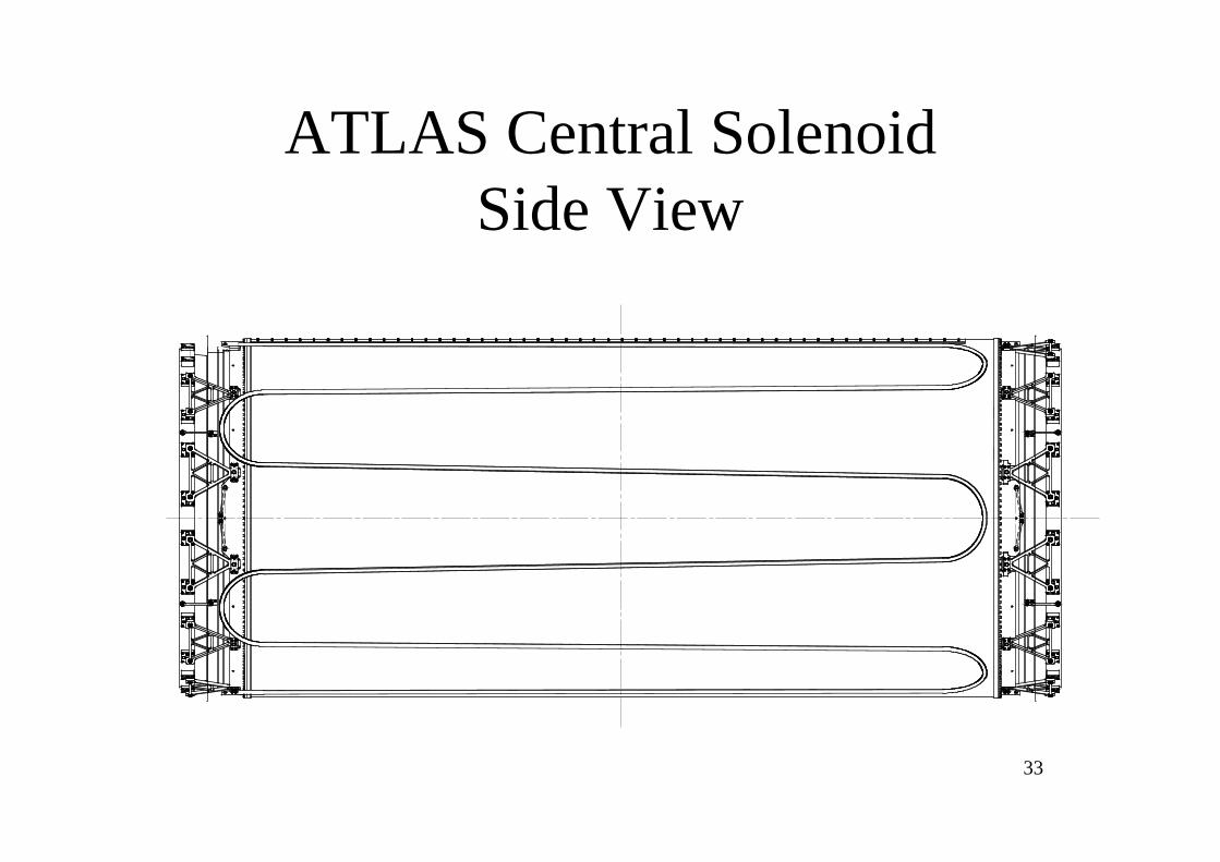
33
ATLAS Central SolenoidSide View
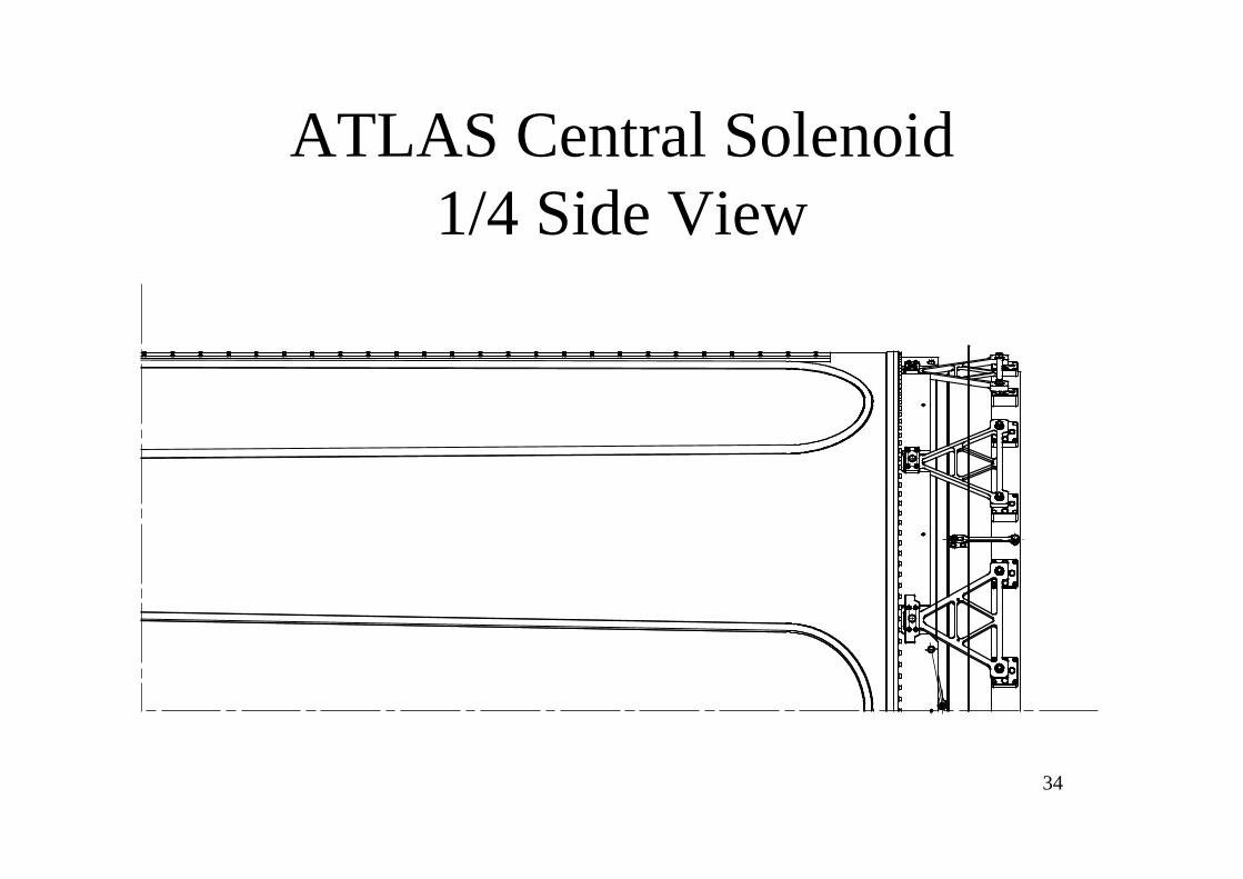
34
ATLAS Central Solenoid1/4 Side View

35
Coil End

36
Support Adjustment
Inner WarmVessel
End Ring
CylinderCoil & Support
Fixture
Spherical bearing
Triangle Support
Eccentric Pin
Bracket Fixture

37
Coil Cross Section

38
Individual Support Strength
0 10 20 30 40 50 60 700
1
2
3
4
5
6
7
8
9
10
Breaking point
Deformation(mm)
Applied Load(kN)
0
1
2
3
4
5
6
7
8
9
10
0 10 20 30 40 50 60 70
Triangle support made of: GFRP woven in six-directionsSpherical bearing at joints: to minimize bending moment
Safe cycle testw/ brackets
One-wayBreaking test
1G1G+2G
Max. Load

39
Triangle Support DesignParameters
Type-A Type-B
Length of cross section(mm2) 20 × 20 20 × 15
Location(degree) 75, 105, 255, 285 15, 45, 135,165, 195,225,315,345
Load condition 2G + Self-weight 2G
Break load(kN) 67.5 46.5
Design load/support(kN) 16.5 11
Design deformation(mm) 1.5 1.2
Safety factor >4 >4
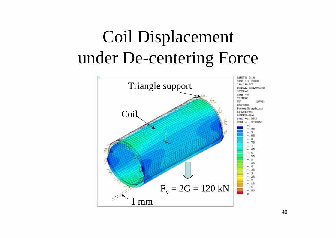
40
Coil Displacementunder De-centering Force
Fy = 2G = 120 kN1 mm
Triangle support
Coil

41
Global Test with 1+2 G
Telescope
Strain Guage
Load
0 deg.
90 deg.
Y
X
Z
D1
D2
D3
dy

42
0 10 20 30 40 50 60 70 80 90 100 110 120-0.2
0.0
0.2
0.4
0.6
0.8
1.0
Deformation(mm)
Applied Load(kN)
Defomation Calculation
0 10 20 30 40 50 60 70 80 90 100 110 1200
5
10
15
20
25
30 Stress Calculation
Applied Load(kN)
Stress(MPa)
-0.2
0.0
0.2
0.4
0.6
0.8
1.0
0
5
10
15
20
25
30
0 10 20 30 40 50 60 70 80 90 100 110 120
0 10 20 30 40 50 60 70 80 90 100 110 120
0 30 60 90 120 150 180 210 240 270 300 330 3600
2
4
6
8
10
12
Measured Force(kN)
Position(degree)
Chimney side Anti-chimney side Calculation
Measured Force
Ex-Load Test Results

43
Position Monitoring
Inner Warm Vessel
Coil

44
End-A Potentiometer

45
Position Sensors at End -A

46
ATLASCS
0.71
6810
4430
13000Control Dewar
Valve Unit
Chimney
LAr Vessel
Solenoid Coil
Unit mm
