atasa 5 efi diagnosis & service - grafton.k12.wi.us · efi diagnosis & service the...
TRANSCRIPT

ATASA 5 th EFI Diagnosis & Service ATASA 5 TH Study Guide Chapter 31 Pages 922948 EFI Diagnosis & Service 47 Points
Please Read The Summary

1. Troubleshooting EFI systems requires ____________ stepbystep test procedures mostly due to the many interrelated components and sensors.
ATASA 5 th EFI Diagnosis & Service
Computer Systematic Automatic

2. The vast majority of complaints about driveability, performance, fuel mileage, roughness, hard starting or nostarting are due to the computer itself (PCM). True or False
ATASA 5 th EFI Diagnosis & Service

3. Sensors are often condemned as defective when the real problem is the engine mechanical condition (known as “base engine”) or the wiring to & from the sensors and the PCM. True or False
Note: Always verify “Base Engine” operation before condemning sensors
ATASA 5 th EFI Diagnosis & Service

4. Before testing EFI & EEC systems verify that the _________, _________ & _________ systems are functioning properly. Check all fuses connections. Verify MIL operation. The engine should be in good _____________ condition, with a quality _____ supply that is not contaminated.
A scan tool alone cannot pinpoint problems with
every little wire or connection or
even every sensor…
A thorough working knowledge
And proper use of the DMM is a necessary for troubleshooting
ATASA 5 th EFI Diagnosis & Service
Battery, Starting, Charging
Mechanical, Fuel

The battery, charging & starting systems, fuel system, vacuum lines, oil & coolant levels, thermostat operation, spark timing and the quality of the fuel all have a direct influence on how the electronic engine control system functions.
ATASA 5 th EFI Diagnosis & Service

5. Sources of heat or sparks that could ignite fuel must be prevented. True or False
ATASA 5 th EFI Diagnosis & Service

6. The EFI system must have good communication with the ______ (Controller Area Network).
ATASA 5 th EFI Diagnosis & Service
MAN CAN TAN

7. The absence of a DTC means the fuel system is operating normally. True or False
ATASA 5 th EFI Diagnosis & Service

8. Observing _______ _______ with a scan tool is a good starting point when diagnosing EFI systems.
ATASA 5 th EFI Diagnosis & Service
Fuel Trim Fuel Rim Fuel Brim

9. Lean “engine conditions” result in __________ FT. Rich “engine conditions” result in __________ FT.
ATASA 5 th EFI Diagnosis & Service
http://www.youtube.com/watch?v=Y4EAyYI67Cw
A cars computer (PCM) can make adjustments to the amount of fuel delivered to it's engine by varying the amount of fuel trim given to an injector pulse. Fuel trim is a percentage of positive or negative correction of fuel delivered, and it is used to keep the optimum fuel ratio to air. Short Term Fuel Trim (STFT) is based off of the Oxygen Sensors reporting of the current Air:Fuel ratio. Long Term Fuel Trim (LTFT) is used by the PCM to keep the STFT as close to zero as it can. These Trims are reported on a per engine bank basis.
http://www.obd2scanners.com/
Positive, Negative Negative, Positive
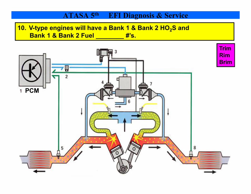
10. Vtype engines will have a Bank 1 & Bank 2 HO 2 S and Bank 1 & Bank 2 Fuel ________ #’s.
ATASA 5 th EFI Diagnosis & Service
PCM
Trim Rim Brim

ATASA 5 th EFI Diagnosis & Service

11. An oxygen sensor can show a “False Lean” reading due to a cylinder ____________.
ATASA 5 th EFI Diagnosis & Service
Campfire Refire Misfire

12. If a HO 2 S response & cycling is slow, the sensor is called “______” and should be replaced.
ATASA 5 th EFI Diagnosis & Service
Motivated Lazy Achiever

13. HO2S voltage stuck low results in fuel trim being _____________. (+%) (lean exhaust = rich command)
ATASA 5 th EFI Diagnosis & Service
Blue Line = Normal Lavender Line = Lean Exhaust
Richened Neutralized Leaned

14. HO2S voltage stuck high results in fuel trim being _________ out. (%) (rich exhaust = lean command)
ATASA 5 th EFI Diagnosis & Service
Blue Line = Normal Red Line = Rich Exhaust
Richened Neutralized Leaned
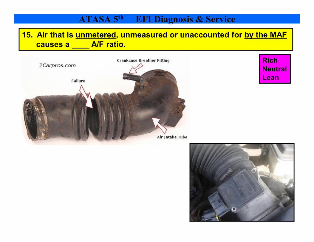
15. Air that is unmetered, unmeasured or unaccounted for by the MAF causes a ____ A/F ratio.
ATASA 5 th EFI Diagnosis & Service
Rich Neutral Lean

16. ___________ ratio sensors are different than oxygen sensors. They will display 2.4 to 4.0 volts.
ATASA 5 th EFI Diagnosis & Service
OilAir AirFuel AirExhaust

ATASA 5 th EFI Diagnosis & Service The operating principle of a titania lambda sensor is entirely different from that of a zirconia lambda sensor. A titania lambda sensor works like a coolant sensor. It changes resistance as the air/fuel ratio goes from rich to lean; but instead of a gradual change, it switches very quickly from low resistance (less than 1000 ohms) when the mixture is rich to high resistance (over 20,000 ohms) when the mixture is lean.
The input end of the titania sensor is fed from a fixed 1volt supply, and the output end is pulled towards 0 volts by a fixed resistor. As the resistance of the titania sensor varies, so does the voltage at its output. When the fuel mixture is rich, the resistance of the sensor is low and so its output voltage is high. When the fuel mixture is lean, resistance shoots up and the voltage signal drops.

17. An airfuel sensor voltage INCREASE with a lean exhaust & DECREASE with a rich exhaust.
ATASA 5 th EFI Diagnosis & Service
When the fuel mixture is rich, the resistance of the sensor is low and so its output voltage is high.
When the fuel mixture is lean, resistance shoots up and the voltage signal drops.
Zirconia Sensor Titania Sensor

ATASA 5 th EFI Diagnosis & Service

18. Peak heater amperage of an A/F sensor can be checked with Mode ___ on the scan tool. (< 6 amps)
ATASA 5 th EFI Diagnosis & Service
$02 $04 $06
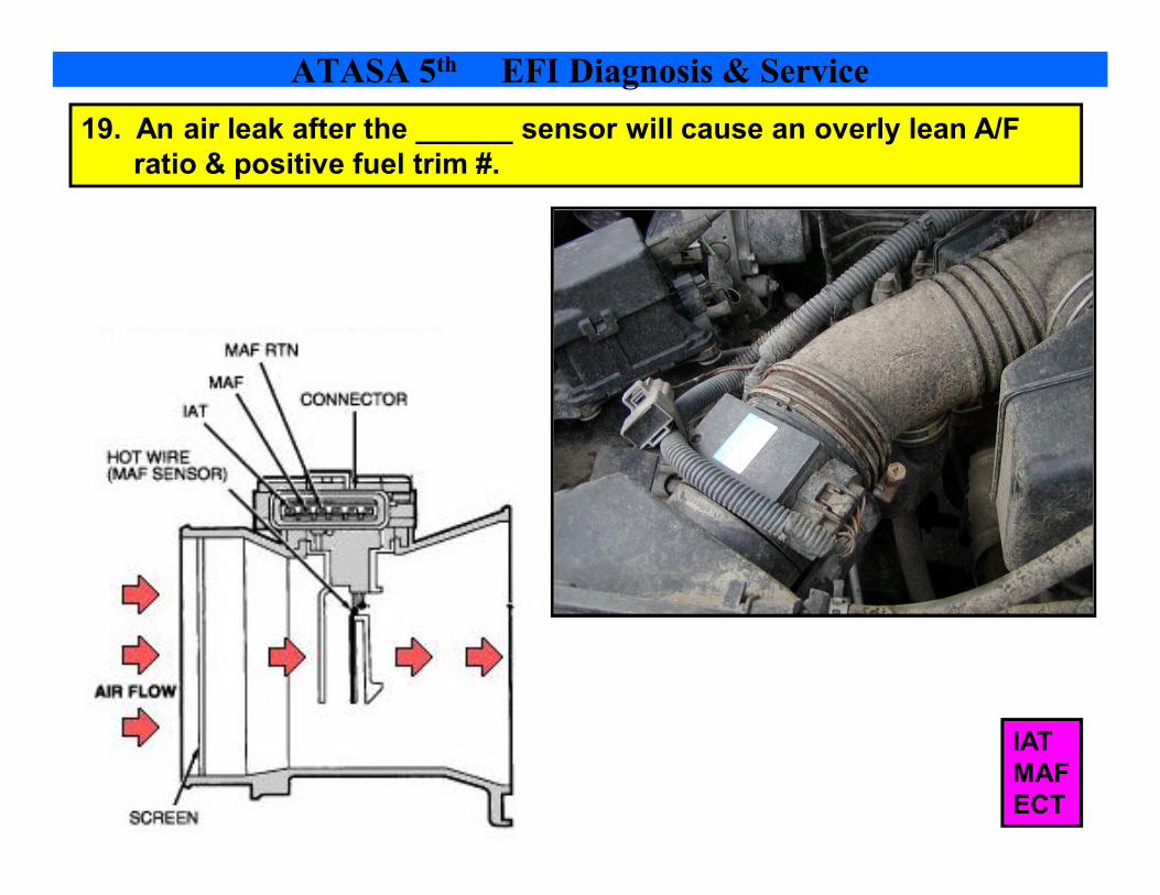
19. An air leak after the ______ sensor will cause an overly lean A/F ratio & positive fuel trim #.
ATASA 5 th EFI Diagnosis & Service
IAT MAF ECT

20. Never soak or immerse the _____ to clean it. Use a special MAF spray cleaner.
ATASA 5 th EFI Diagnosis & Service
IAT MAF ECT

21. If the MAF hot wire is dirty, check the “________ ______” relay or observe the burnoff cycle.
ATASA 5 th EFI Diagnosis & Service
Burnoff Turnoff Ripoff

22. Vacuum leaks in a MAP speed density system can be verified by watching ______ “counts”. (counts are steps open from the closed position)
ATASA 5 th EFI Diagnosis & Service
IAC MAP MAF

ATASA 5 th EFI Diagnosis & Service
The number of “counts” indicates how many steps out from the closed position the IAC is positioned at to bypass air for idle

ATASA 5 th EFI Diagnosis & Service

23. Throttle ____________, IACs, and intake manifold runners may need to be cleaned of deposits.
ATASA 5 th EFI Diagnosis & Service
Plates & Bores Angles Angels
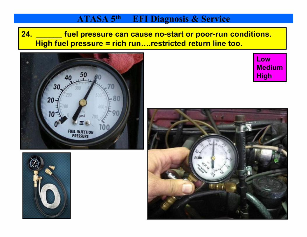
24. ______ fuel pressure can cause nostart or poorrun conditions. High fuel pressure = rich run….restricted return line too.
ATASA 5 th EFI Diagnosis & Service
Low Medium High

25. A __________ injector can be diagnosed with a warm engine shut off, an exhaust analyzer probed into the intake plenum area. A high HC reading that does not drop indicates injector leaks.
ATASA 5 th EFI Diagnosis & Service
Short Leaking Clogged

26. An injector circuit can be checked for voltage switching with a ________ light or logic probe.
ATASA 5 th EFI Diagnosis & Service
Noid Thyroid Droid

27. Injector coils can be tested with an ohmmeter for _____ & opens. _____________ tests will help identify a restricted injector. A stethoscope can also be used to listen for the click.
ATASA 5 th EFI Diagnosis & Service
Shorts, Bleedown Blockage, Bleedown Leaking, Bleedown

28. A lab scope can be used to closely observe injector __________ waveforms & _________ ramps.
ATASA 5 th EFI Diagnosis & Service
Resistance, Current Voltage, Current Wattage, Current

28. A lab scope can be used to closely observe injector __________ waveforms & _________ ramps.
ATASA 5 th EFI Diagnosis & Service
Resistance, Current Voltage, Current Wattage, Current
Check the Vertical Axis
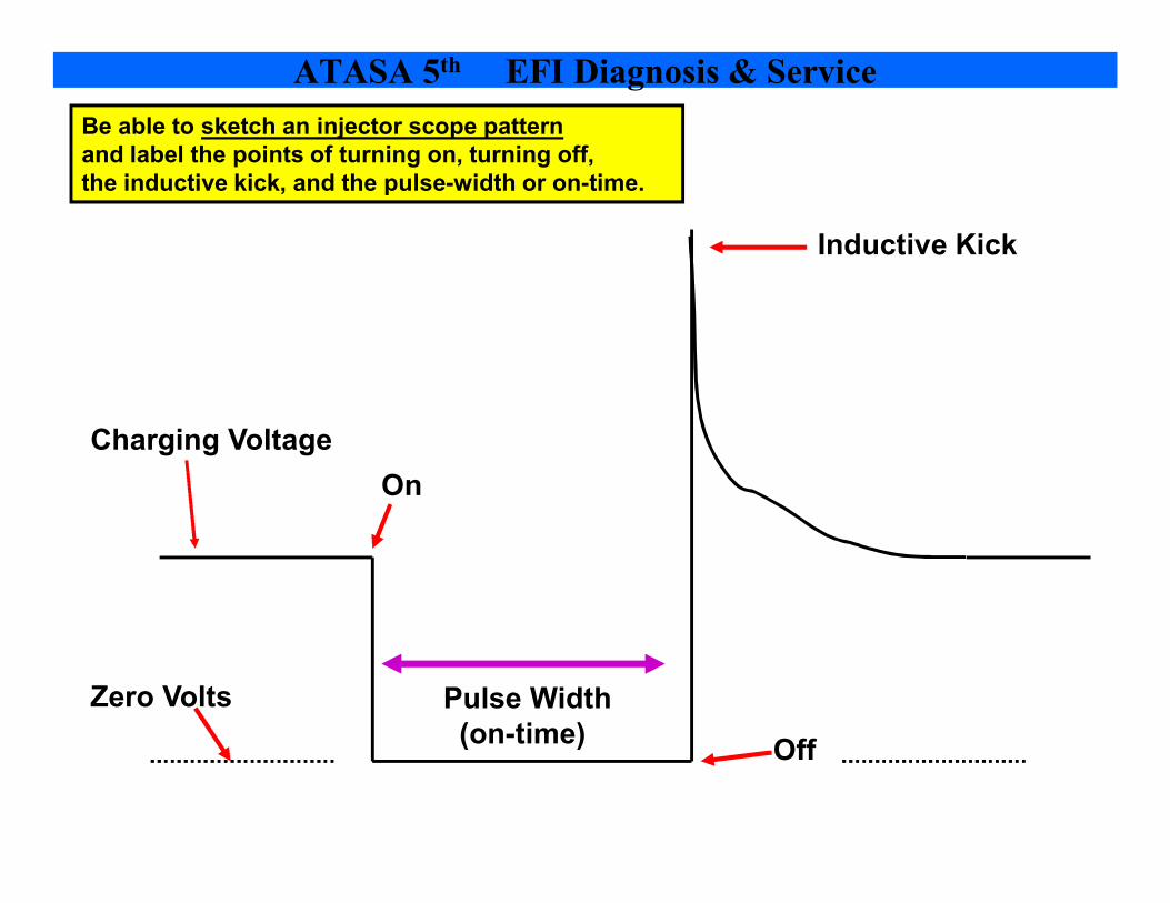
Be able to sketch an injector scope pattern and label the points of turning on, turning off, the inductive kick, and the pulsewidth or ontime.
On
Off
Inductive Kick
Pulse Width (ontime)
Charging Voltage
Zero Volts
ATASA 5 th EFI Diagnosis & Service

On
Off
Inductive Kick
Pulse Width (ontime)
Charging Voltage
Zero Volts If Injector does not pull down to zero line, There is a groundside voltage drop either in the PCM or the injector circuitry.
ATASA 5 th EFI Diagnosis & Service

29. Injectors can be ___________ by running a chemical through them to dissolve deposits.
ATASA 5 th EFI Diagnosis & Service
Cleaned Deodorized Sanitized

30. During cleaning procedures, cleaning pressure should be about ____ psi under fuel system psi.
ATASA 5 th EFI Diagnosis & Service
5 psi 20 psi 50 psi

31. After cleaning injectors, drive the vehicle to allow _____________ memory to relearn trims.
ATASA 5 th EFI Diagnosis & Service
Adaptive Reactive Permanent
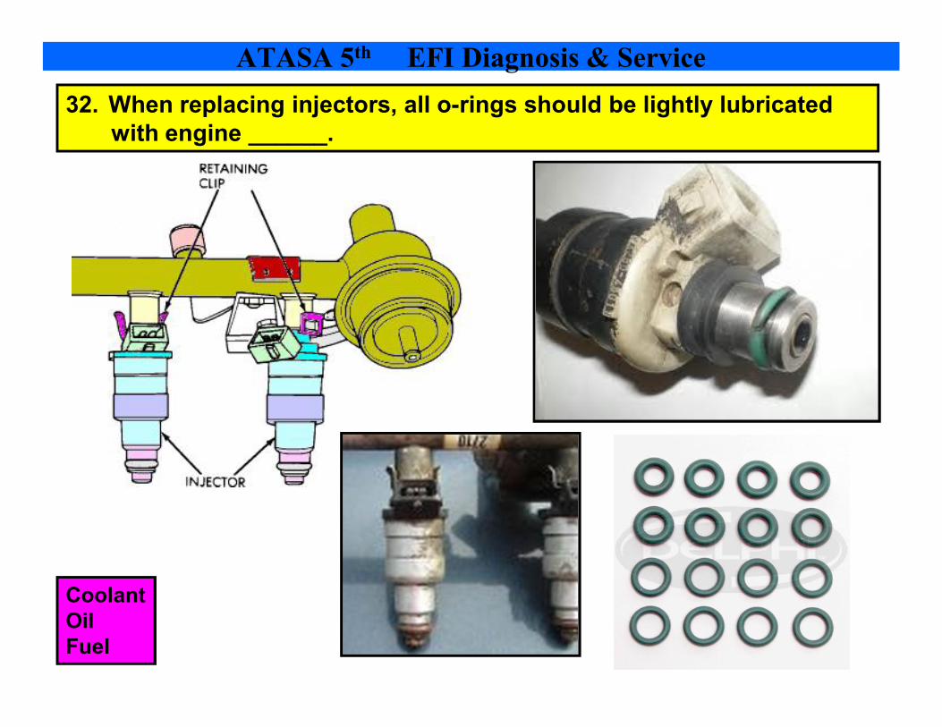
32. When replacing injectors, all orings should be lightly lubricated with engine ______.
ATASA 5 th EFI Diagnosis & Service
Coolant Oil Fuel

33. After fuel rail R & R and injector replacement start the engine & check for ________.
ATASA 5 th EFI Diagnosis & Service
Ohms Volts Leaks

34. An electronic throttle control system has 2 ____ sensors, 2 ______ sensors, and 2 driver circuits for the throttle actuator motor – one that opens the plate & one that closes it.
ATASA 5 th EFI Diagnosis & Service
TP, APP TP, BPP TP, FTP
Accelerator Pedal Position Sensors
Throttle Position Sensors
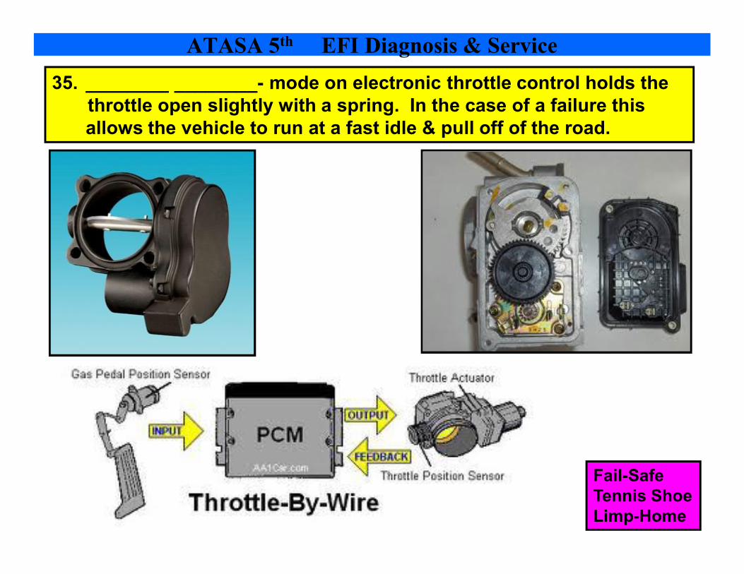
35. ________ ________ mode on electronic throttle control holds the throttle open slightly with a spring. In the case of a failure this allows the vehicle to run at a fast idle & pull off of the road.
ATASA 5 th EFI Diagnosis & Service
FailSafe Tennis Shoe LimpHome

36. If the battery is disconnected & reconnected, the PCM will go through an idle __________ procedure automatically. If the PCM is replaced, the relearn procedure may be more extensive.
ATASA 5 th EFI Diagnosis & Service
ReCalibration ReLearn ReTool
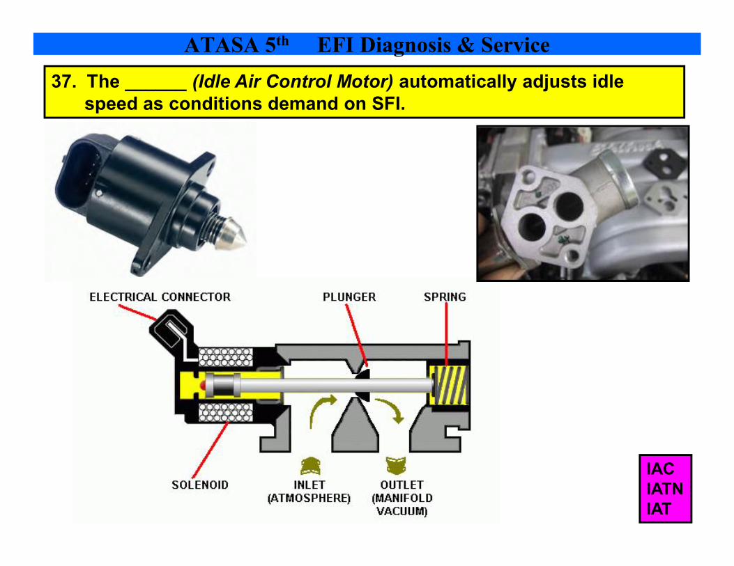
37. The ______ (Idle Air Control Motor) automatically adjusts idle speed as conditions demand on SFI.
ATASA 5 th EFI Diagnosis & Service
IAC IATN IAT

38. Scan tools can bidirectionally control the IAC _____________ & pintle to verify operation.
ATASA 5 th EFI Diagnosis & Service
Motor Armature Rotor

Diagnostic Trouble Codes are read with scan tools or on some OBD I vehicles, can be read by counting the blinking MIL when put into the field service mode.
ATASA 5 th EFI Diagnosis & Service

ATASA 5 th EFI Diagnosis & Service
GM Ford
Dodge Toyota

Lean exhaust due to Large amounts of oxygen produces Low voltages at the EGOS. (.1 to .4)
.450 volts or 450 millivolts is the middle range for an EGOS. It’s also the PCM generated voltage during open loop until the HO2S becomes responsive.
ATASA 5 th EFI Diagnosis & Service

Rich exhaust due to small amounts of oxygen produces high voltages at the upstream HO 2 S. (.5 .9 volts ) or (500 to 900 millivolts)
ATASA 5 th EFI Diagnosis & Service

The activity or switching of an oxygen sensor can be best monitored with a Lab Scope.
A slowresponding or lazy EGOS is hard to detect with a scan tool…lab scopes rule for this! (also called DSO’s Digital Storage Oscilloscopes
ATASA 5 th EFI Diagnosis & Service

Injector pulse width is adjusted in response to upstream HO2S readings. This adjustment to injector ontime, expressed in percentage of fuel added or subtracted from the norm is known as fuel trim.
STFT = integrator & LTFT = block learn
ATASA 5 th EFI Diagnosis & Service

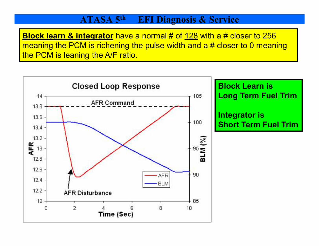
Block learn & integrator have a normal # of 128 with a # closer to 256 meaning the PCM is richening the pulse width and a # closer to 0 meaning the PCM is leaning the A/F ratio.
Block Learn is Long Term Fuel Trim
Integrator is Short Term Fuel Trim
ATASA 5 th EFI Diagnosis & Service

ATASA 5 th EFI Diagnosis & Service

ATASA 5 th EFI Diagnosis & Service
ATASA 5 th EFI Diagnosis & Service

ATASA 5 th EFI Diagnosis & Service

A restricted injector can cause a lean misfire, resulting in EGOS stuck low, rich command from the PCM, a CO problem, and a HC problem due to lean misfire condition in the cylinder. (tough logic to follow!)
ATASA 5 th EFI Diagnosis & Service

ATASA 5 th EFI Diagnosis & Service

An injector balance test is done using a pressure gauge & an EFI pulse tester. Injectors can also be diagnosed by listening to their operation with a technician’s electronic stethoscope.
ATASA 5 th EFI Diagnosis & Service

ATASA 5 th EFI Diagnosis & Service

ATASA 5 th EFI Diagnosis & Service

ATASA 5 th EFI Diagnosis & Service
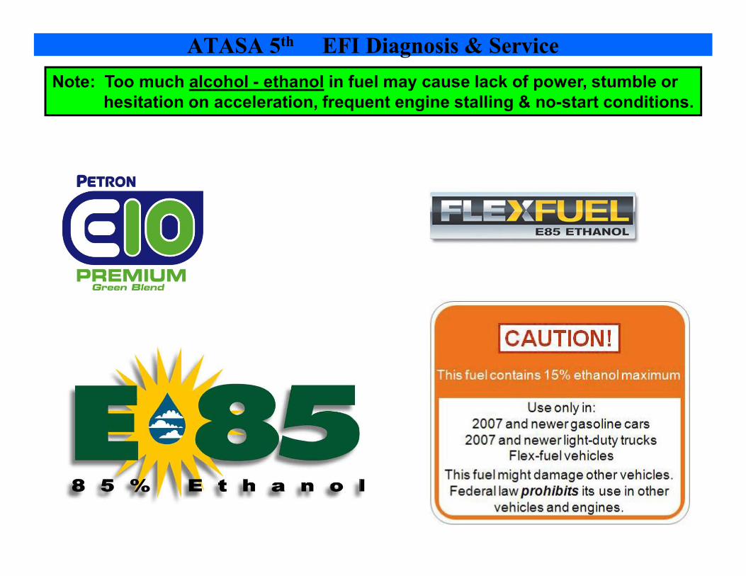
Note: Too much alcohol ethanol in fuel may cause lack of power, stumble or hesitation on acceleration, frequent engine stalling & nostart conditions.
ATASA 5 th EFI Diagnosis & Service

ATASA 5 th EFI Diagnosis & Service

ATASA 5 th EFI Diagnosis & Service
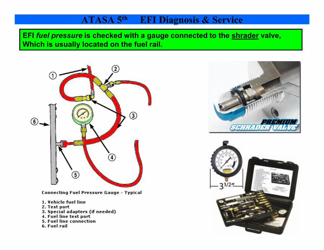
EFI fuel pressure is checked with a gauge connected to the shrader valve, Which is usually located on the fuel rail.
ATASA 5 th EFI Diagnosis & Service

ATASA 5 th EFI Diagnosis & Service Some EFI systems, especially TBI types, use a pulsation damper to control fluctuations. The fluctuation is due more to the single injector opening & closing than the fuel pump operation.

Remember: A vacuumsensitive fuel pressure regulator increases the psi as the engine vacuum drops…more psi @WOT!
ATASA 5 th EFI Diagnosis & Service

ATASA 5 th EFI Diagnosis & Service

ATASA 5 th EFI Diagnosis & Service

ATASA 5 th EFI Diagnosis & Service

Be able to explain in your own words why engine vacuum is lower under heavy acceleration or WOT:
Vacuum is caused by the intake strokes pulling against a closed throttle plate.
If the throttle plate is open for acceleration, the vacuum is more like atmospheric pressure.
A vacuum gauge reading is a comparison of engine pressure to atmospheric pressure.
With the throttle plate open, the pressures are closer to equaling each other. This causes a closer to zero pressure difference, or in other words zero vacuum.
ATASA 5 th EFI Diagnosis & Service