“at the beginning of the project and prior to performing ... · san antonio river outfall...
TRANSCRIPT
San Antonio River Outfall Pipeline, Project No. 2B Addendum No. 1
SAWS Job No. 13-4510 (Sewer) 1
SAN ANTONIO WATER SYSTEM
San Antonio River Outfall Pipeline Project No. 2B
SAWS Job No. 13-4510 (Sewer)
Solicitation No. CO-00017
ADDENDUM NO. 1
September 9, 2015
TO BIDDER OF RECORD:
The following changes, additions, and/or deletions are hereby made a part of the Contract Documents
for the construction of the San Antonio River Outfall Pipeline Project No. 2B, for the San Antonio
Water System, San Antonio, Texas, dated August 2015, as fully and completely as if the same were
set forth therein.
PART 1 - BIDDING AND CONTRACT DOCUMENTS
1. SPECIAL CONDITIONS:
REPLACE Paragraph 1.5, Sentence 2 with the following:
“At the beginning of the project and prior to performing any excavation and
construction activities in the area of the fiber optic line, Contractor must coordinate
with AT&T by calling Darren Jones (AT&T) at (210) 283-1603 to confirm the fiber
optic line location and method for relocation as needed.”
PART 2 - TECHNICAL SPECIFICATIONS
1. SECTION 02623 – FIBERGLASS REINFORCED PIPE (FRP):
REPLACE Paragraph 2.02 E with the following:
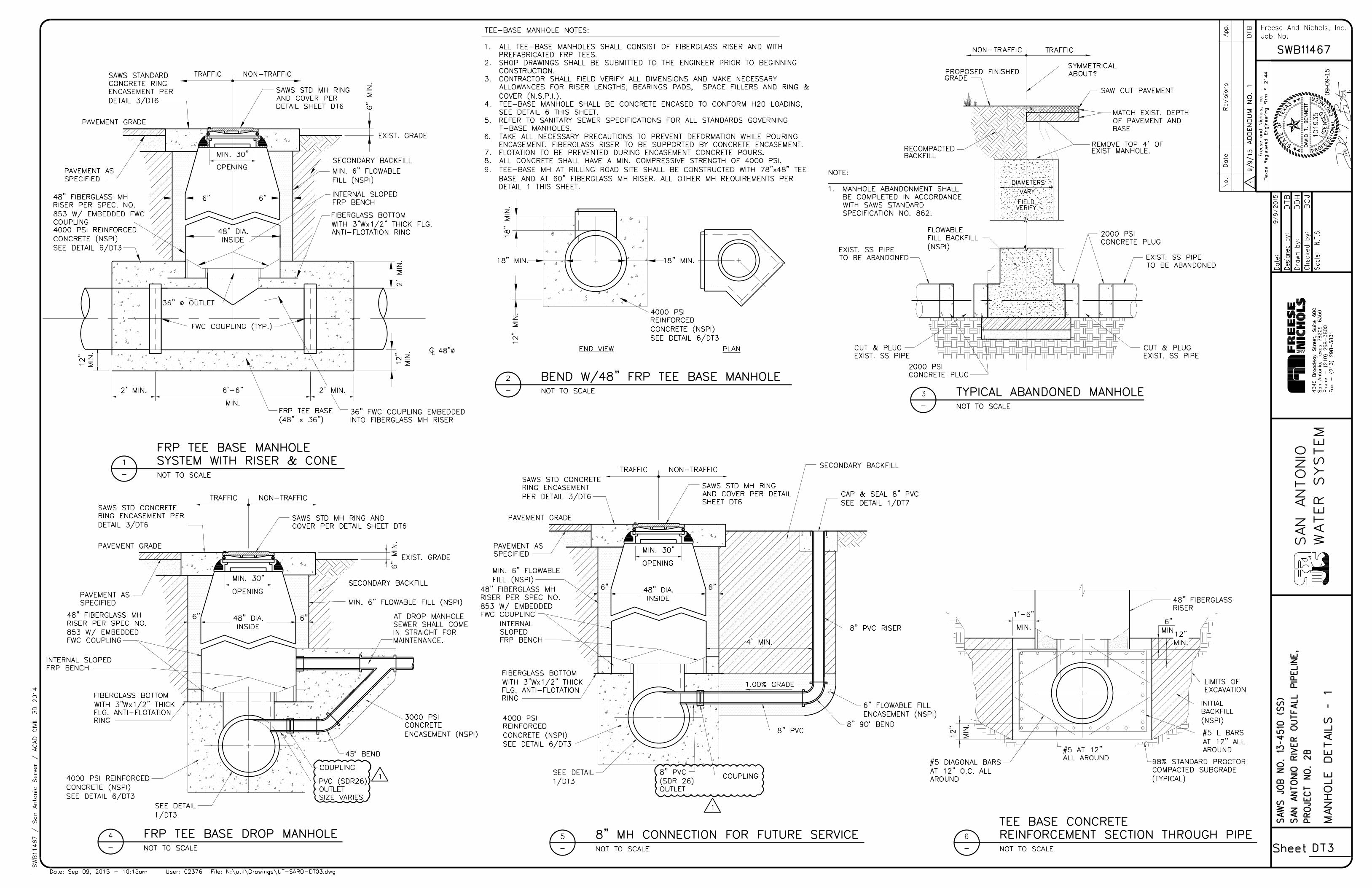
“E. Tee Based Manhole fittings shall be made with fiberglass pipe and shall include a 36-
inch diameter outlet connecting the manhole riser to the pipe.”
2. SECTION 15113 – STOP LOG AND FRAMES:
REPLACE this section in its entirety with the attached section.
PART 3 – DRAWINGS
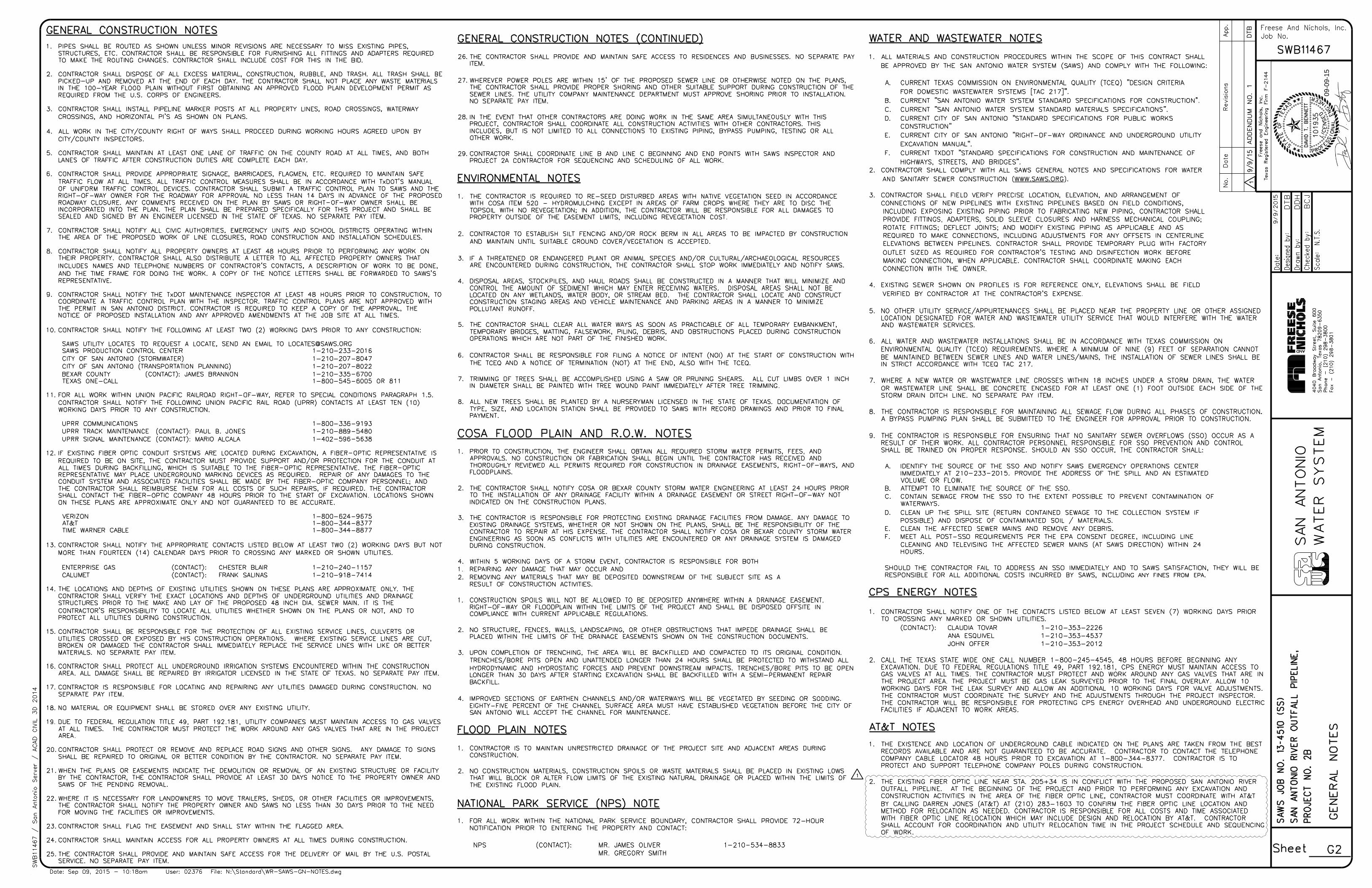
1. SHEET G2 – GENERAL NOTES:
REPLACE this sheet in its entirety with the attached sheet.
2. SHEET PL4 – LINE ‘C’ PLAN & PROFILE STA. 153+00 TO STA. 162+00:
REPLACE this sheet in its entirety with the attached sheet.

San Antonio River Outfall Pipeline, Project No. 2B Addendum No. 1
SAWS Job No. 13-4510 (Sewer) 2
3. SHEET PL9 – LINE ‘C’ PLAN & PROFILE STA. 200+00 TO STA. 210+00:
REPLACE this sheet in its entirety with the attached sheet.
4. SHEET DT3 – MANHOLE DETAILS - 1:
REPLACE this sheet in its entirety with the attached sheet.
5. SHEET DT6 – MANHOLE DETAILS - 5:
REPLACE this sheet in its entirety with the attached sheet.
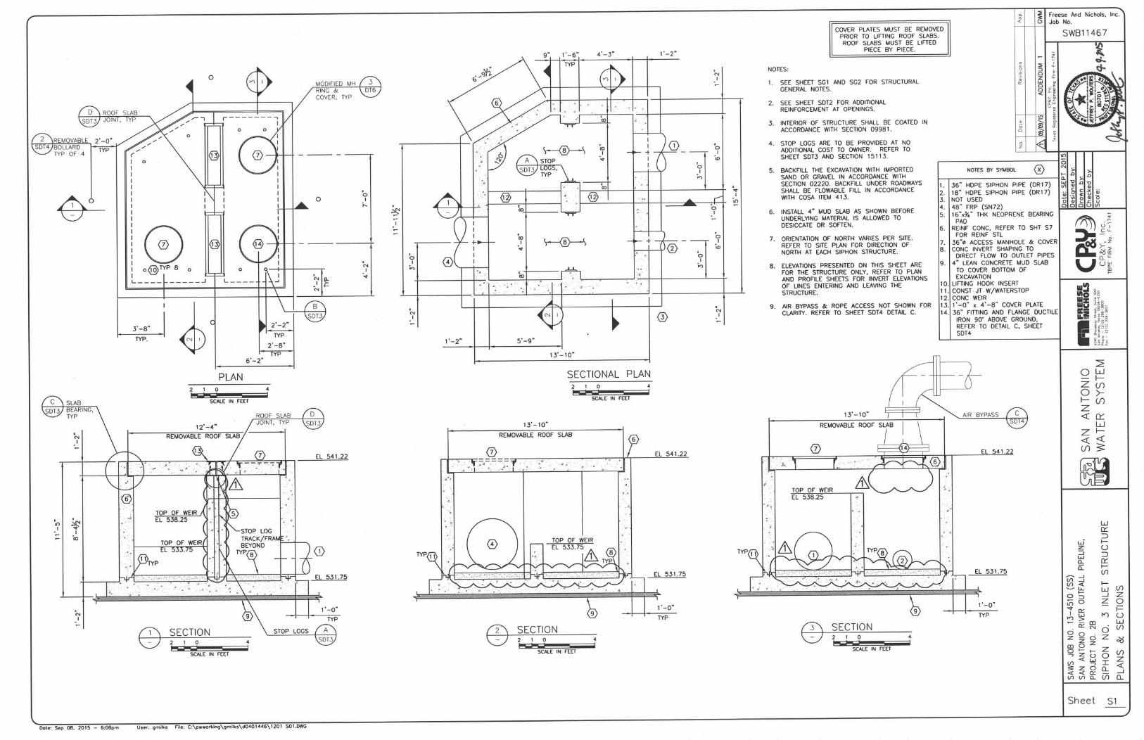
6. SHEET S1 – SIPHON NO. 3 - INLET STRUCTURE PLANS & SECTIONS:
REPLACE this sheet in its entirety with the attached sheet.
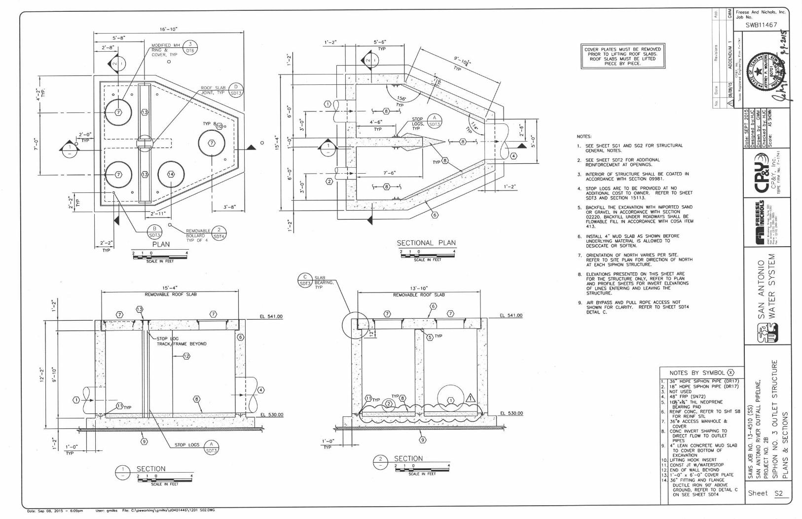
7. SHEET S2 – SIPHON NO. 3 - OUTLET STRUCTURE PLANS & SECTIONS:
REPLACE this sheet in its entirety with the attached sheet.
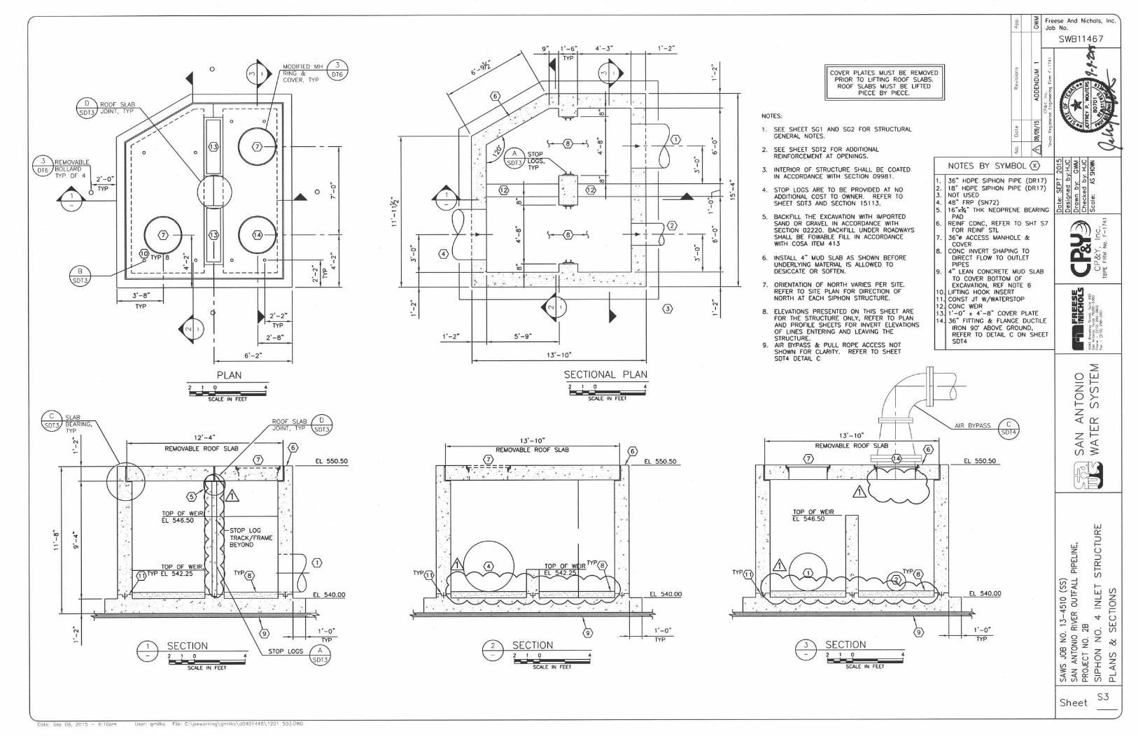
8. SHEET S3 – SIPHON NO. 4 - INLET STRUCTURE PLANS & SECTIONS:
REPLACE this sheet in its entirety with the attached sheet.
9. SHEET S4 – SIPHON NO. 4 - OUTLET STRUCTURE PLANS & SECTIONS:
REPLACE this sheet in its entirety with the attached sheet.
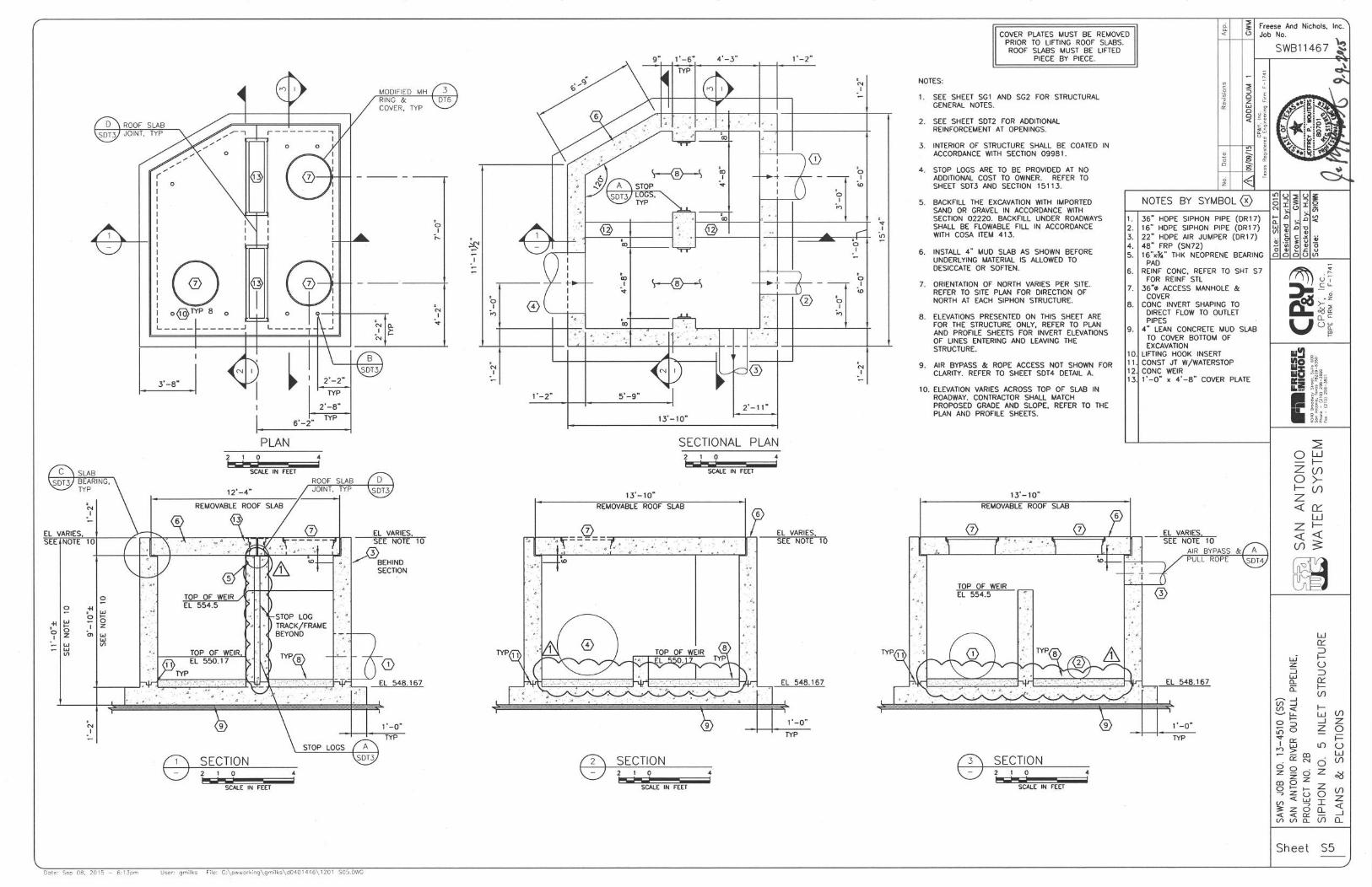
10. SHEET S5 – SIPHON NO. 5 - INLET STRUCTURE PLANS & SECTIONS:
REPLACE this sheet in its entirety with the attached sheet.
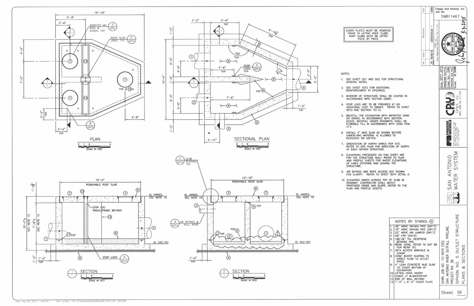
11. SHEET S6 – SIPHON NO. 5 - OUTLET STRUCTURE PLANS & SECTIONS:
REPLACE this sheet in its entirety with the attached sheet.
12. SHEET SDT3 – STRUCTURAL DETAILS III:
REPLACE this sheet in its entirety with the attached sheet.
13. SHEET SDT4 – STRUCTURAL DETAILS IV:
REPLACE this sheet in its entirety with the attached sheet.

San Antonio River Outfall Pipeline, Project No. 2B Addendum No. 1
SAWS Job No. 13-4510 (Sewer) 3
ALL BIDDERS SHALL ACKNOWLEDGE RECEIPT OF ADDENDUM NO. 1 IN THE BID
FORM AND BY HIS/HER SIGNATURE AFFIXED HERETO AND TO FILE SAME AS AN
ATTACHMENT TO HIS/HER BID. BID FORMS SUBMITTED WITHOUT THIS
ACKNOWLEDGEMENT WILL BE CONSIDERED INFORMAL.
_____________________________________
David T. Bennett, P.E.
Freese and Nichols, Inc.
ACKNOWLEDGEMENT BY BIDDER
THE UNDERSIGNED ACKNOWLEDGES RECEIPT OF THIS ADDENDUM NO. 1 AND THE BID
SUBMITTED HEREWITH IS IN ACCORDANCE WITH THE INFORMATION AND STIPULATION
SET FORTH.
Date Signature of bidder
Appended hereto and part of Addendum No. 1 are:
1. SECTION 15113
2. PLANS (Revised Sheets)
a. SHEET G2
b. SHEET PL4
c. SHEET PL9
d. SHEET DT3
e. SHEET DT6
f. SHEET S1
g. SHEET S2
h. SHEET S3
i. SHEET S4
j. SHEET S5
k. SHEET S6
l. SHEET SDT3
m. SHEET SDT4
3. Contractor Questions and Answers
END OF ADDENDUM NO. 1
09/09/2015

San Antonio River Outfall Pipeline, Project No. 2B Stop Log and Frames
SAWS Job No. 13-4510 15113-1
SECTION 15113
STOP LOG AND FRAMES
PART 1 GENERAL
1.01 SCOPE OF WORK
A. This Section includes the furnishing and the subsequent installation of fabricated stainless steel
stop log frames and stop logs, complete with all other appurtenances necessary for a complete
and operating installation, as shown on Plans and as specified herein.
1.02 RELATED WORK
A. Division 1: General Requirements.
B. Division 5: Metals.
C. Division 3: Concrete.
1.03 SUBMITTALS
A. Submittals shall be prepared and submitted in accordance with San Antonio Water System
General Conditions.
B. Submittals shall include a firm production and delivery schedule of stop logs, frames, and all
accessories. The production and delivery schedule shall consider normal submittal review time
as specified in San Antonio Water System General Conditions and shall be in accordance with
the construction schedule specified in Specification Item No. 1110 – Progress Schedule.
C. The following submittals are required, at a minimum, in addition to the applicable requirements
of San Antonio Water System General Conditions.
1. Detailed drawings specific to the stop logs and frames provided with dimensions and
weights.
2. Construction features and materials of construction with ASTM designations.
3. List of any deviations from the requirements of these specifications.
4. Design and detail of the stop log frame brackets and anchor bolts.
5. Engineering data and descriptive literature for all stop logs.
6. MANUFACTURER’s installation and testing instructions, including leakage testing
instructions and storage recommendations.
7. Welding procedures and qualifications. Stop log frames shall be welded using the welding
process described in AWS D1.6 or ASME Section IX. Welders and welding processes
shall be qualified and maintained as required by AWS D1.6 Section 4. Visual inspections
shall be according to AWS D1.6 Section 6.
8. Other information necessary for complete review by ENGINEER.
D. Start-up and test schedule.
E. Field test data and test records.
F. Provide an Affidavit of Compliance according to AWWA C561, Article 6.3.
G. O&M Manuals in accordance with San Antonio Water System General Conditions.
H. Partial or incomplete submittals will not be reviewed by the ENGINEER.

San Antonio River Outfall Pipeline, Project No. 2B Stop Log and Frames
SAWS Job No. 13-4510 15113-2
1.04 REFERENCES
A. The publications listed below form a part of this specification to the extent referenced. The
publications are referred to in the text by basic designation only.
B. AMERICAN SOCIETY OF TESTING MATERIALS (ASTM)
1. ASTM A240 Standard Specification for Chromium and Chromium-Nickel Stainless Steel
Plate, Sheet, and Strip for Pressure Vessels and for General Applications
2. ASTM A276 Standard Specification for Stainless Steel Bars and Shapes
3. ASTM B584 Standard Specification for Copper Alloy Sand Castings for General
Applications
4. ASTM D2000 Standard Classification System for Rubber Products in Automotive
Applications
5. ASTM D3935 Standard Specification for Polycarbonate (PC) Unfilled and Reinforced
Material
6. ASTM D4020 Standard Specification for Ultra-High-Molecular-Weight Polyethylene
Molding and Extrusion Materials
7. ASTM F593 Standard Specification for Stainless Steel Bolts, Hex Cap Screws, and Studs
8. ASTM F594 Standard Specification for Stainless Steel Nuts
C. AMERICAN SOCIETY OF MECHANICAL ENGINEERS (ASME)
D. AMERICAN WELDING SOCIETY (AWS)
E. INTERNATIONAL STANDARD ORGANIZATION (ISO)
1.05 QUALITY ASSURANCE
A. Minimum 10 years’ experience in production of equipment substantially similar to the
equipment specified
B. Stop log frame MANUFACTURER shall have experience in the production of substantially
similar equipment, and shall provide evidence of satisfactory operation in at least 20 separate
installations. At least 5 installations shall have a minimum of 5 years in service.
C. MANUFACTURER’s shop welds, welding procedures, and welders shall be qualified and
certified in accordance with the requirements of the latest edition of ASME, Section IX or
AWS D1.6.
D. Stop log frames and stop logs shall be shop inspected for proper operation prior to shipping.
E. Stop log frame MANUFACTURER shall be ISO 9001 certified or approved equal quality
control measures.
F. The stop log frame MANUFACTURER shall furnish a qualified field representative for a
minimum of 1 working day per structure to inspect all equipment described herein after
installation, to advise CONTRACTOR and OWNER during start-up and testing, and to instruct
OWNER's personnel in routine maintenance and troubleshooting procedures. CONTRACTOR
shall coordinate the scheduling of such training and start-up assistance with the OWNER.
G. MANUFACTURER's installation report is required prior to final acceptance.
H. All stop log frames and stop logs specified in this section shall be supplied by a single
MANUFACTURER.
San Antonio River Outfall Pipeline, Project No. 2B Stop Log and Frames
SAWS Job No. 13-4510 15113-3
1.06 PRODUCT DELIVERY, STORAGE AND HANDLING
A. Handle all appurtenances with care. Frames, stop logs and appurtenances which are cracked,
chipped, distorted or otherwise damaged or dropped will not be acceptable. Protect all threads,
seats, ends, etc. from damage and corrosion.
B. Store all frames, stop logs and appurtenances in approved enclosed shelter or properly covered
and off the ground, and in accordance with MANUFACTURER’s recommendations.
C. Stop log frames shall be delivered to the site fully assembled. Stop log frames shall not be
delivered to the site in sections for assembly by the CONTRACTOR.
1.07 WARRANTY
A. Provide two year warranty under provisions of the General Conditions.
PART 2 PRODUCTS
2.01 MANUFACTURER(S)
A. Fabricated stainless steel stop log frames and stop logs shall be manufactured by one of the
following:
1. Fontaine Industries, Ltd.
2. Whipps
3. HydroGate Corp.
2.02 MATERIALS AND/OR EQUIPMENT
A. General
1. All materials used in the fabrication of stop logs and frames for shall be inherently
corrosion resistant where exposed to raw wastewater.
2. Minimum thickness of any structural member, shall be 0.25 inches unless otherwise
specified.
3. All welds shall be passivated.
4. Stop logs and frames shall be designed for installation and operation to accommodate the
clearances and limitations available in the proposed structure.
5. Stop logs and frames shall be substantially watertight with leakage not to exceed 0.1 gpm
per foot of seating perimeter at design seating head.
6. Field welding is not permitted.
B. Performance
1. Stop logs and frames shall be substantially watertight under the design head conditions as
shown in the Stop Log Frame Schedule.
a. Under design seating head, leakage shall not exceed 0.10 gallons per minute per foot
of seating perimeter.
b. Under design unseating head, leakage shall not exceed 0.10 gallons per minute per
foot of seating perimeter.
2. The stop log’s sealing system shall have been tested through a cycle test in an abrasive
environment and should show the leakage requirements are still obtained after 25,000
cycles with minimum deterioration. Documentation of testing shall be provided with
submittal drawings.
C. Materials
1. Frame: Stainless steel, ASTM A276, Type 316/316L
2. Stop Log: Stainless steel, ASTM A276, Type 316L
3. Guides: Ultra-high-molecular-weight polyethylene (UHMWPE), ASTM D-4020

San Antonio River Outfall Pipeline, Project No. 2B Stop Log and Frames
SAWS Job No. 13-4510 15113-4
4. Side and Top Seals: UHMWPE, ASTM D4020
5. Bottom Seal: Resilient neoprene, ASTM D2000 Grade 2 BC 510
6. Fasteners: Stainless steel, ASTM F593 or F594 GR2
7. Gasket (between frame and wall): EPDM
D. All required attaching bolts; anchor bolts and accessories shall be furnished with the equipment
and shall be Type 316 stainless steel. Anchor bolts shall be minimum diameter of 0.75 inches.
E. Frame
1. Frame shall be constructed of 316/316L structural members or formed plate welded to
form a rigid one-piece frame. Minimum thickness 0.25 inches.
2. Frame shall be of a design suitable for mounting as detailed in the project plans. Should
structural modifications be necessary, CONTRACTOR shall be required to retain the
services of an Engineer licensed in the State of Texas, at no additional cost to the
OWNER, to design the revisions, signed and sealed plans and calculations shall be
submitted to ENGINEER for review. Necessary work required to meet the revised design
shall be completed by CONTRACTOR at no additional cost to OWNER.
3. Frame configuration shall be of the flush-bottom type and shall allow the replacement of
the top and side seals without removing the frame from the wall.
4. Design for maximum design head specified in the stop log schedule, with a minimum
safety factor of 5 for the ultimate tensile, compressive and shear strength.
F. Stop Log
1. Stop Log shall consist of a type 316L flat plate reinforced with formed plates or structural
members to limit deflection to 1/1000 of the stop log’s span under the maximum design
head or 0.0625 inch whichever is less. Minimum thickness 0.25 inch.
2. Provide two lifting hooks/bars and stoppers welded to the stop log to allow an alternate
lifting method to be used to unseat and lift the stop log. Design each hook/bar to be
capable of lifting the stop log against maximum design head conditions.
3. Each stop log shall be limited to a maximum of 6.25 inches in height.
4. Provide a lifting devise capable of locking and lifting the stop logs provided.
G. Guides and Seals
1. Guides shall be of such length as to support the slide fully in the open position.
2. Minimum face width of 1-inch
3. J-seals shall not be acceptable
4. Field replaceable without removing frame.
5. Anchor bolts shall not pass through guides and seals
6. Seating and sliding surface shall provide a low coefficient of friction with the surface of
the slide
7. Side and top seals shall be of one of the alternative designs below
a. Seal Design A shall be a UHMWPE fixed sealing surface that surrounds the clear
opening. It shall be held in place in the guide by 316 stainless steel fasteners. The seal
compression may be maintained by UHMWPE filed adjustable pressure pads
mounted to the slide with 316 stainless steel fasteners.
b. Seal Design B shall be a neoprene crown seal with UHMWPE bearing bars attached
to the slide with 316 stainless steel fasteners. The crown seal shall be actuated by
water pressure in either the seating or unseating direction. Primary contact with the
slide shall be through the UHMWPE bearing bar. The neoprene shall not be solely
relied upon for the contact seal. Seal compression may be maintained by UHMWPE
field adjustable pressure pads mounted to the guide with 316 stainless steel fasteners.
c. Seal Design C shall be UHMWPE self-adjusting type seals utilizing a continuous
compression cord or pad to ensure contact between the seals and the slide. Side seals
shall be held in place between the front and back angles of the guide or within a
San Antonio River Outfall Pipeline, Project No. 2B Stop Log and Frames
SAWS Job No. 13-4510 15113-5
single piece mounting. Side seal held in place in the guide with 316 stainless steel
bolts. Top seal UHMWPE self-adjusting type with compression cord or pad.
8. The sealing system shall maintain efficient sealing in any position of the slide and allow
the water to flow only in the opened part of the frame from either direction.
9. The bottom seal shall be set into the bottom member of the frame or mounted on the
bottom of the slide and shall form a flush-bottom. The bottom seal shall be mechanically
fastened to the bottom member of the frame or the slide. Bottom seals that are attached
through the use of adhesives only are not acceptable.
H. Protective Coating
1. Coat all moving surfaces with waterproof grease. Paint is not required for stainless steel
surfaces.
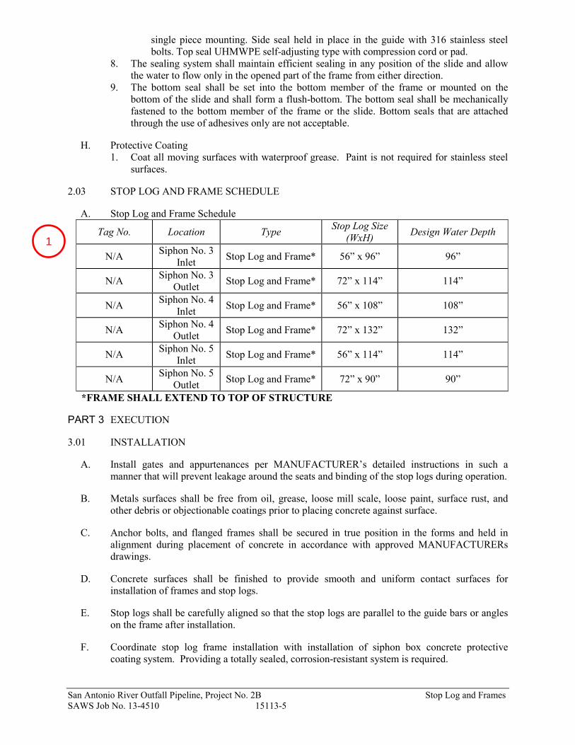
2.03 STOP LOG AND FRAME SCHEDULE
A. Stop Log and Frame Schedule
Tag No. Location Type Stop Log Size
(WxH) Design Water Depth
N/A Siphon No. 3
Inlet Stop Log and Frame* 56” x 96” 96”
N/A Siphon No. 3
Outlet Stop Log and Frame* 72” x 114” 114”
N/A Siphon No. 4
Inlet Stop Log and Frame* 56” x 108” 108”
N/A Siphon No. 4
Outlet Stop Log and Frame* 72” x 132” 132”
N/A Siphon No. 5
Inlet Stop Log and Frame* 56” x 114” 114”
N/A Siphon No. 5
Outlet Stop Log and Frame* 72” x 90” 90”
*FRAME SHALL EXTEND TO TOP OF STRUCTURE
PART 3 EXECUTION
3.01 INSTALLATION
A. Install gates and appurtenances per MANUFACTURER’s detailed instructions in such a
manner that will prevent leakage around the seats and binding of the stop logs during operation.
B. Metals surfaces shall be free from oil, grease, loose mill scale, loose paint, surface rust, and
other debris or objectionable coatings prior to placing concrete against surface.
C. Anchor bolts, and flanged frames shall be secured in true position in the forms and held in
alignment during placement of concrete in accordance with approved MANUFACTURERs
drawings.
D. Concrete surfaces shall be finished to provide smooth and uniform contact surfaces for
installation of frames and stop logs.
E. Stop logs shall be carefully aligned so that the stop logs are parallel to the guide bars or angles
on the frame after installation.
F. Coordinate stop log frame installation with installation of siphon box concrete protective
coating system. Providing a totally sealed, corrosion-resistant system is required.
1

San Antonio River Outfall Pipeline, Project No. 2B Stop Log and Frames
SAWS Job No. 13-4510 15113-6
G. After the frame has been installed, clean, lubricate, and otherwise service the frame and stop
logs per MANUFACTURER’s instructions.
3.02 SHOP TESTING
A. Each frame and stop log shall be fully assembled and shop-inspected in the vertical position for
proper seating.
B. Stop logs shall be fully installed and removed from frame to ensure that it operates freely.
3.03 PAINTING AND COATINGS
A. All machined iron surfaces including drilled and tapped holes shall be completed with a heavy
coat of protective grease.
3.04 FIELD TESTING
A. Operate installed frame and stop logs a minimum of three full cycles in the presence of the
OWNER to demonstrate satisfactory operation. CONTRACTOR shall make any changes
and/or adjustments necessary to ensure satisfactory operation of the frame and stop log system.
All testing equipment required shall be provided by the CONTRACTOR.
B. Perform leakage test in presence of the OWNER per the requirements of this Specification
Section.
3.05 MANUFACTURER'S SERVICE
Provide the service of qualified, factory-trained representative of the MANUFACTURER to
check and approve each part of the installation before it is placed in operation. He shall instruct
the OWNER personnel in operation, care and maintenance of all frames, stop logs and
appurtenances and supervise initial operation. Special tools, if required for normal operations
and maintenance, shall be furnished with the equipment by the MANUFACTURER.
PART 4 MEASUREMENT AND PAYMENT
4.01 MEASUREMENT
A. Description
1. This item shall be for furnishing all design, submittals, labor, materials, tools, equipment
and incidentals required to approve and construct the structures. The item applies to the
following structures listed:
a. Siphon Inlet Structure #3
b. Siphon Outlet Structure #3
c. Siphon Inlet Structure #4
d. Siphon Outlet Structure #4
e. Siphon Inlet Structure #5
f. Siphon Outlet Structure #5
4.02 MEASUREMENT
A. Measurement of the item "Stop Log and Frames” is measured by the dimensions provided in
the plans drawings and materials stated herein or as indicated by OWNER and ENGINEER,
and is incidental to the Bid Items identified by the following:
a. Siphon Inlet Structure #3 measured by each
b. Siphon Outlet Structure #3 measured by each
c. Siphon Inlet Structure #4 measured by each

San Antonio River Outfall Pipeline, Project No. 2B Stop Log and Frames
SAWS Job No. 13-4510 15113-7
d. Siphon Outlet Structure #4 measured by each
e. Siphon Inlet Structure #5 measured by each
f. Siphon Outlet Structure #5 measured by each
4.03 PAYMENT
A. Payment shall constitute full compensation to the CONTRACTOR for furnishing all labor,
equipment, tools, and materials, and for performing all operations required to furnish to the
OWNER. Payment for this item shall be incidental to the following Bid Items:
a. Siphon Inlet Structure #3
b. Siphon Outlet Structure #3
c. Siphon Inlet Structure #4
d. Siphon Outlet Structure #4
e. Siphon Inlet Structure #5
f. Siphon Outlet Structure #5
B. There shall be no separate pay item for this work
END OF SECTION
09-0
9-15

BID QUANTITIES
ITEM NO DESCRIPTION QUANTITY UNIT
02623-48a 48" FRP GRAVITY SEWER LINE (INSTALL BY OPEN CUT), SN 46 (ALL DEPTHS) 900 LF
550 TRENCH EXCAVATION SAFETY PROTECTION 900 LF
SS-853-1 48" FRP TEE BASE MANHOLE 3 EA
SS-853-4 TEE BASE MANHOLE EXTRA DEPTH > 15 FT 15 VF
862-2 ABANDON EXISTING MANHOLE 2 EA
520 SEEDING 8700 SY
09-0
9-15

BID QUANTITIES
ITEM NO DESCRIPTION QUANTITY UNIT
02623-48a 48" FRP GRAVITY SEWER LINE (INSTALL BY OPEN CUT), SN 46 (ALL DEPTHS) 849 LF
848-10 10" PVC GRAVITY SEWER LINE, D3034, SDR-26 (ALL DEPTHS) 15 LF
856-66 66" STEEL CASING (BY BORE/TUNNEL) 151 LF
02623-48d 48" FRP GRAVITY SEWER LINE, SN 46, CARRIER PIPE WITHIN CASING PIPE 151 LF
550 TRENCH EXCAVATION SAFETY PROTECTION 864 LF
SS-853-1 48" FRP TEE BASE MANHOLE 2 EA
862-2 ABANDON EXISTING MANHOLE 3 EA
2218-1 CELLULAR GROUT FILL OF EXISTING 48" SANITARY SEWER LINE 150 LF
508-1 REMOVE AND REPLACE BARBED WIRE FENCE (STEEL OR WOOD POSTS) 100 LF
508-3 INSTALL 16' TYPE 1 OR TYPE 2 GATE 2 EA
845 PIPELINE MARKER 2 EA
520 SEEDING 7600 SY
09-0
9-15
09-0
9-15

09-0
9-15


1
QUESTIONS AND ANSWERS
1. Question: The Uni-Bell PVC Pipe Association on behalf of our member companies,
respectfully requests that the San Antonio Water System modify the plans,
specifications, and bid documents through an addendum to include the use of PVC pipe
where it is applicable for the San Antonio River Outfall Pipeline Project No. 2B.
1. Answer: The project has been designed with FRP as the pipe material. No alternate
material will be considered.
2. Question: I’m the local rep for Diamond Plastics. We respectfully requests that the San
Antonio Water System modify the plans, specifications, and bid documents through an
addendum to include the use of PVC pipe where it is applicable for the San Antonio
River Outfall Pipeline Project No. 2B. I would also like to add that Diamond has
experience in making PS75. We shipped over 15,000’ of 30” PS75 to Austin back in
2012, and we also have the tooling available to make it in 48”.
2. Answer: See response to Question #1.
3. Question: Can you please clarify the required DN48 pipe stiffness for the pipe detailed
on sheet PL4 between MH-13 and MH-14. A pipe stiffness of SN72 is called out for the
pipe in the profile view, however only a pipe stiffness of SN46 is shown in the bid
quantities table on this page. There is similar conflicting information on sheet PL9 that
requires clarification, for the pipe required between MH-21 and MH-22.
3. Answer: The quantities table is correct. The pipe stiffness class was mislabeled on
the sheet profiles. See Addendum No. 1, Part 3, Item Nos. 2 and 3.
4. Question: Specifications 03740 Concrete Modification & Repair.
Is that in the specifications as incidental on an as need basis or is there repair work to
be done? As specialty trade contractors, established in 1977, we repair, protect and
strengthen existing concrete structures in commercial, industrial and marine
environments. I have attached some information on our firm for your review.
4. Answer: The specification is for incidental work. There are no scheduled repairs in
this project.
5. Question: Take a look at the attached stop log schedule under section 15113 par. 2.03.
I’m trying to figure out how many 6” high logs to price.

2
Under “Stop Log size” the heights are shown to be 78” & 60” high, respectively and
this is clear and fine. However, the next column is confusing things, because all the
stop log heights based on that 30” from the center line would be slightly different.
Can you get a clarification from Engineer regarding the actual distance to top stop log
for each Siphon location? This will have an impact on pricing.
5. Answer: A revised schedule is issued with Addendum No. 1, Part 2, Item No. 2.
6. Question: Will SAWS offer a pre-bid meeting on site with sufficient stakes in place to
establish the proposed centerline? Without granting the contractors full access to the
job site, we cannot accurately bid the full scope of work. The contractor needs to
establish ROW conditions, fencing conditions, livestock present in the construction
areas, a possibility to dig more test holes, entrance/exit points for deliveries and low
areas for spoil waste etc.
6. Answer: The project alignment is available for Bidders to inspect. SAWS is not
providing staking.
7. Question: Will SAWS furnish the existing flow charts in a gallon per minute so we can
accurately figure the full cost of bypassing? If not, will SAWS provide full access to
all existing structures we will be bypassing from so the contractor and his pump
supplies can establish what will be required in the bypassing operation? This will
require the structures to be open and lids removed.
7. Answer: Flow information is not available. Contractor shall confirm bypass
pumping flow during submittal of the Bypass Pumping Plan in accordance with
ITEM NO. 864 BYPASS PUMPING, Section 864.3, which states, “In the absence of
any flow data furnished in the contract documents, the Contractor’s submitted flow
data will be the only means to incorporate the to-be submitted BPP for review and
acknowledgment.”
8. Question: Specification Section 02623 calls for tee base neck to be 30” where plans
show 36” neck size. Please clarify.
8. Answer: Tee base manhole shall have a 36” diameter outlet connecting the manhole
riser to the pipe. See Addendum No. 1, Part 2, Item No. 1.
9. Question: Detail 4 and 5 of sheet DT-3 call for lateral out of tee base to be FRP
material for connection to PVC. Standard Tee base manholes are built with PVC (SDR
26) pipe as laterals. Please confirm lateral stub out built on tee base to be PVC pipe.
9. Answer: Outlets shall be PVC (SDR 26). See Addendum No. 1, Part 3, Item No. 4.
3
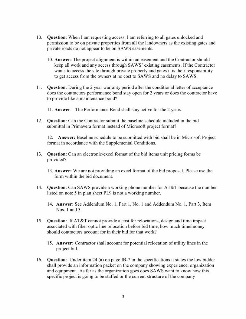
10. Question: When I am requesting access, I am referring to all gates unlocked and
permission to be on private properties from all the landowners as the existing gates and
private roads do not appear to be on SAWS easements.
10. Answer: The project alignment is within an easement and the Contractor should
keep all work and any access through SAWS’ existing easements. If the Contractor
wants to access the site through private property and gates it is their responsibility
to get access from the owners at no cost to SAWS and no delay to SAWS.
11. Question: During the 2 year warranty period after the conditional letter of acceptance
does the contractors performance bond stay open for 2 years or does the contractor have
to provide like a maintenance bond?
11. Answer: The Performance Bond shall stay active for the 2 years.
12. Question: Can the Contractor submit the baseline schedule included in the bid
submittal in Primavera format instead of Microsoft project format?
12. Answer: Baseline schedule to be submitted with bid shall be in Microsoft Project
format in accordance with the Supplemental Conditions.
13. Question: Can an electronic/excel format of the bid items unit pricing forms be
provided?
13. Answer: We are not providing an excel format of the bid proposal. Please use the
form within the bid document.
14. Question: Can SAWS provide a working phone number for AT&T because the number
listed on note 5 in plan sheet PL9 is not a working number.
14. Answer: See Addendum No. 1, Part 1, No. 1 and Addendum No. 1, Part 3, Item
Nos. 1 and 3.
15. Question: If AT&T cannot provide a cost for relocations, design and time impact
associated with fiber optic line relocation before bid time, how much time/money
should contractors account for in their bid for that work?
15. Answer: Contractor shall account for potential relocation of utility lines in the
project bid.
16. Question: Under item 24 (a) on page IB-7 in the specifications it states the low bidder
shall provide an information packet on the company showing experience, organization
and equipment. As far as the organization goes does SAWS want to know how this
specific project is going to be staffed or the current structure of the company

4
organization. Also can items 24 (a)-(e) be provided in one binder or does each item
need to be in separate binders or packets?
16. Answer: SAWS requires the current structure of the company organization as well
as the project specific staff. Information requested can be provided in one packet.
17. Question: Can SAWS provide Flow charts for all the existing sewer lines to be
effected during construction?
17. Answer: See response to Question #7.
18. Question: Section 01030, Special Procedures, 1.01,D references critical areas for
installation, bypass pumping and sequencing of the proposed sanitary sewer line and
manholes and connections. These areas are referenced lines A through F. Can the flow
rate information for each of these areas be provided for bidding purposes?
18. Answer: See response to Question #17.