at-mmc6005 series - allied telesis | network … by interconnecting lan devices that are physically...
TRANSCRIPT

AT-MMC6005 SeriesVDSL Mini Media Converters
AT-MMC6005 AT-MMC6005-E
Installation Guide
613-002120 Rev. A

Copyright 2016 Allied Telesis, Inc.All rights reserved. No part of this publication may be reproduced without prior written permission from Allied Telesis, Inc.Allied Telesis and the Allied Telesis logo are trademarks of Allied Telesis, Incorporated. All other product names, company names, logos or other designations mentioned herein are trademarks or registered trademarks of their respective owners.Allied Telesis, Inc. reserves the right to make changes in specifications and other information contained in this document without prior written notice. The information provided herein is subject to change without notice. In no event shall Allied Telesis, Inc. be liable for any incidental, special, indirect, or consequential damages whatsoever, including but not limited to lost profits, arising out of or related to this manual or the information contained herein, even if Allied Telesis, Inc. has been advised of, known, or should have known, the possibility of such damages.

Electrical Safety and Emissions Standards
This section contains the following:
“US Federal Communications Commission”
“Industry Canada”
“Emissions, Immunity and Electrical Safety Standards” on page 4
“Translated Safety Statements” on page 4
US Federal Communications CommissionRadiated Energy
NoteThis equipment has been tested and found to comply with the limits for a Class A digital device pursuant to Part 15 of FCC Rules. These limits are designed to provide reasonable protection against harmful interference when the equipment is operated in a commercial environment. This equipment generates, uses, and can radiate radio frequency energy and, if not installed and used in accordance with this instruction manual, may cause harmful interference to radio communications. Operation of this equipment in a residential area is likely to cause harmful interference in which case the user will be required to correct the interference at his own expense.
NoteModifications or changes not expressly approved of by the manufacturer or the FCC, can void your right to operate this equipment.
Industry CanadaRadiated Energy
This Class A digital apparatus complies with Canadian ICES-003.
Cet appareil numérique de la classe A est conforme à la norme NMB-003 du Canada.
3

Emissions, Immunity and Electrical Safety Standards
RFI Emissions FCC Class A, EN55022 Class A, CISPR 22 Class A, VCCI Class A, RCM
WarningIn a domestic environment this product may cause radio interference in which case the user may be required to take adequate measures. E84
EMC (Immunity) EN55024, EN61000-3-2, EN61000-3-3
Electrical Safety EN60950-1 (TUV), UL 60950-1 (CULUS)
WarningLaser Safety: EN60825 L7
Translated Safety Statements
Important: The indicates that a translation of the safety statement is available in a PDF document titled Translated Safety Statements on the Allied Telesis website at www.alliedtelesis.com/support.
4

Contents
Preface............................................................................................................................................................. 11Document Conventions.............................................................................................................................. 12Contacting Allied Telesis............................................................................................................................ 13
Chapter 1: Product Description ..................................................................................................................... 15Introduction ................................................................................................................................................ 16Summary of Features................................................................................................................................. 17Overview .................................................................................................................................................... 18Location of Components ............................................................................................................................ 19Feature Description.................................................................................................................................... 20
VDSL Line Port .................................................................................................................................... 20VDSL2 Profiles and Settings ............................................................................................................... 2110/100/1000 Mbps Twisted Pair Ethernet Port .................................................................................... 23Status LEDs......................................................................................................................................... 25DIP Switches ....................................................................................................................................... 27Smart MissingLink™ (SML)................................................................................................................. 27DC Power Supply Input Port................................................................................................................ 29External AC/DC Power Adapter .......................................................................................................... 29
Chapter 2: Installation ................................................................................................................................... 31Installation Safety Precautions................................................................................................................... 32Selecting a Site for the Media Converter ................................................................................................... 34Cables Not Included................................................................................................................................... 35Unpacking the Media Converter................................................................................................................. 36Installing the AT-MMC6005 Subscriber Unit .............................................................................................. 37
Using the Subscriber Unit on a Desktop.............................................................................................. 37Wall-Mounting the Subscriber Unit ...................................................................................................... 37Setting the DIP Switches ..................................................................................................................... 40Cabling the Subscriber Unit ................................................................................................................. 40Powering On the Subscriber Unit ........................................................................................................ 41
Installing the AT-MMC6005 Provider Unit.................................................................................................. 43Using the Provider Unit on a Desktop ................................................................................................. 43Wall-Mounting the Provider Unit .......................................................................................................... 43Setting the DIP Switches ..................................................................................................................... 44Cabling the Provider Unit..................................................................................................................... 44Powering On the Provider Unit ............................................................................................................ 45
Chapter 3: Troubleshooting .......................................................................................................................... 47
Appendix A: Technical Specifications ............................................................................................................ 49Physical Specifications............................................................................................................................... 49Environmental Specifications ..................................................................................................................... 49Power Specifications.................................................................................................................................. 50Safety and Electromagnetic Emissions Certifications ................................................................................ 50RJ45 Connector and Port Pinouts.............................................................................................................. 51
5

Contents
6

Figures
Figure 1: Media Converter System Topology ...................................................................................................................... 18Figure 2: Front Panel ........................................................................................................................................................... 19Figure 3: Rear Panel ........................................................................................................................................................... 19Figure 4: AT-MMC6005 Series Converter Rear Panel DIP Switches.................................................................................. 21Figure 5: AT-MMC6005 in Subscriber (Up/CPE) Position ................................................................................................... 27Figure 6: SML in Normal Condition with Two Media Converters ......................................................................................... 28Figure 7: SML with Copper Connection to End Node Down................................................................................................ 28Figure 8: SML in ON Position .............................................................................................................................................. 29Figure 9: Shipping Package Contents ................................................................................................................................. 36Figure 10: Attaching the Brackets to Install the Media Converter on a Wall........................................................................ 37Figure 11: Marking the Screw Hole Locations..................................................................................................................... 38Figure 12: Securing the Media Converter to the Wall.......................................................................................................... 39Figure 13: Ethernet to Computer ......................................................................................................................................... 40Figure 14: VDSL Line to Wall/Interior Phone Line............................................................................................................... 41Figure 15: Connecting 12VDC Powered Unit ...................................................................................................................... 42Figure 16: Ethernet to Internet Service Provider ................................................................................................................. 44Figure 17: VDSL Line to Wall/Interior Phone Line............................................................................................................... 44Figure 18: RJ45 Connector and Port Pin Layout ................................................................................................................. 51
7

List of Figures
8
Tables
Table 1. VDSL - RJ11 Port Pinouts ....................................................................................................................................20Table 2. VDSL2 DIP Switch Settings - Profiles, Description, Usage ..................................................................................22Table 3. VDSL2 DIP Switch Settings - Additional Information ............................................................................................23Table 4. Twisted-Pair Port Cabling Specifications ..............................................................................................................24Table 5. Status LEDs ..........................................................................................................................................................25Table 6. Cables ..................................................................................................................................................................35Table 7. Physical Specifications .........................................................................................................................................49Table 8. Environmental Specifications - AT-MMC6005 ......................................................................................................49Table 9. Environmental Specifications - AT-MMC6005-E ..................................................................................................50Table 10. Power Specifications ..........................................................................................................................................50Table 11. Safety and Electromagnetic Emissions Certifications .........................................................................................50Table 12. MDI Pin Signals (10 or 100 Mbps) ......................................................................................................................51Table 13. MDI-X Pin Signals (10 or 100 Mbps) ..................................................................................................................51Table 14. Pin Signals (1000 Mbps) .....................................................................................................................................52
9

List of Tables
10

Preface
This preface contains the following sections:
“Document Conventions” on page 12
“Contacting Allied Telesis” on page 13
This guide contains instructions on how to install and configure the AT-MMC6005.
11

Document Conventions
This document uses the following conventions:
NoteNotes provide additional information.
CautionCautions inform you that performing or omitting a specific action may result in equipment damage or loss of data.
WarningWarnings inform you that performing or omitting a specific action may result in bodily injury.
12

AT-MMC6005 Installation Guide
Contacting Allied Telesis
If you need assistance with this product, you may contact Allied Telesis technical support by going to the Support & Services section of the Allied Telesis web site at www.alliedtelesis.com/support. You can find links for the following services on this page:
24/7 Online Support — Enter our interactive support center to search for answers to your product questions in our knowledge database, to check support tickets, to learn about RMAs, and to contact Allied Telesis technical experts.
USA and EMEA phone support — Select the phone number that best fits your location and customer type.
Hardware warranty information — Learn about Allied Telesis warranties and register your product online.
Replacement Services — Submit a Return Merchandise Authorization (RMA) request via our interactive support center.
Documentation — View the most recent installation and user guides, software release notes, white papers, and data sheets for your products.
Software Downloads — Download the latest software releases for your managed products.
For sales or corporate information, go to www.alliedtelesis.com/purchase and select your region.
13

14

Chapter 1
Product Description
This chapter contains the following sections:
“Introduction” on page 16
“Summary of Features” on page 17
“Overview” on page 18
“Location of Components” on page 19
“Feature Description” on page 20
This chapter describes the following media converters:
AT-MMC6005
AT-MMC6005-E
15

Product Description
Introduction
The AT-MMC6005 Series VDSL Mini Media Converters are designed to transmit data at very high speeds over unshielded pairs of copper wires using VDSL2 technology. They also can extend the distance of your network by interconnecting LAN devices that are physically separated by large distances.
The difference between the AT-MMC6005 and AT-MMC6005-E is the temperature rating. Refer to “Technical Specifications” on page 49 for temperature ratings.
NoteIn this guide, the AT-MMC6005 and AT-MMC6005-E will be referred to collectively as AT-MMC6005 or media converter.
16
AT-MMC6005 Installation Guide
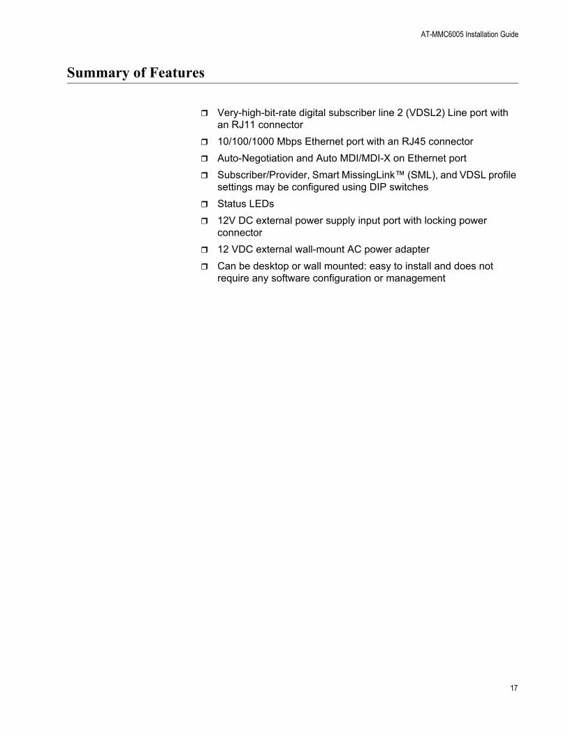
Summary of Features
Very-high-bit-rate digital subscriber line 2 (VDSL2) Line port with an RJ11 connector
10/100/1000 Mbps Ethernet port with an RJ45 connector
Auto-Negotiation and Auto MDI/MDI-X on Ethernet port
Subscriber/Provider, Smart MissingLink™ (SML), and VDSL profile settings may be configured using DIP switches
Status LEDs
12V DC external power supply input port with locking power connector
12 VDC external wall-mount AC power adapter
Can be desktop or wall mounted: easy to install and does not require any software configuration or management
17

Product Description
Overview
This device can be used in multi-dwelling units (MDU), multi-tenant buildings (MTU), and in the hospitality industry, such as airports, hotels, and convention centers.
This product is sold in pairs with one AT-MMC6005 unit configured as the Subscriber and one AT-MMC6005 unit configured as the Provider. In an MDU, such as a university dormitory, the Subscriber unit would be installed in each room and connected to a Provider unit through the telephone outlet, which could be located in the building wiring closet.
The AT-MMC6005 can be used as a desktop or wallmount device. Refer to “Installing the AT-MMC6005 Provider Unit” on page 43 for installation details.
When both AT-MMC6005 units have been installed, the media converter system topology shown in Figure 1 is complete.
Figure 1. Media Converter System Topology
VDSL Line throughwall/interior phone line
AT-MMC6005Subscriber
Unit
AT-MMC6005Provider
Unit
Computer’sEthernet Port
InternetServiceProvider
18

AT-MMC6005 Installation Guide
Location of Components
Figure 2 illustrates the front panel of the AT-MMC6005.
Figure 2. Front Panel
Figure 3 illustrates the rear panel of the AT-MMC6005.
Figure 3. Rear Panel
Ethernet Port
DSL LED
VDSL Line Port
Ethernet PortL/A LED
Ethernet PortDuplex/Collision
LED
System LED
DC Power Supply Port
DIP Switches
19

Product Description
Feature Description
The following sections describe the hardware features of the AT-MMC6005 media converters:
”VDSL Line Port”
“VDSL2 Profiles and Settings” on page 21
“10/100/1000 Mbps Twisted Pair Ethernet Port” on page 23
“Status LEDs” on page 25
“DIP Switches” on page 27
“Smart MissingLink™ (SML)” on page 27
“DC Power Supply Input Port” on page 29
“External AC/DC Power Adapter” on page 29
VDSL Line Port The VDSL Line port allows you to connect the AT-MMC6005 Subscriber unit to a telephone jack (wall outlet) and the AT-MMC6005 Provider unit to the inside phone line at the wiring closet. The two units need to be within 3 km of each other in order for the port to operate properly. The port transmits Ethernet data at frequencies of 300 KHz to 30 MHz. This port features an RJ11 connector.
Table 1 lists the RJ11 port pinouts and their assignments.
Table 1. VDSL - RJ11 Port Pinouts
Pin Assignment
1 Not connected
2 Not connected
3 VDSL and phone ring
4 VDSL and phone tip
5 Not connected
6 Not connected
20

AT-MMC6005 Installation Guide
VDSL2 Profilesand Settings
The AT-MMC6005 in CPE (Subscriber) mode supports all VDSL2 profiles defined by ITU-T G.993.2. The AT-MMC6005 in CO (Provider) mode allows the user to select from a predetermined list of profiles (see Table 2 on page 22 and Table 3 on page 23 for details).
VDSL2 functionality is set using DIP switches 2, 3, and 4. The DIP switches are shown in Figure 4.
Figure 4. AT-MMC6005 Series Converter Rear Panel DIP Switches
Table 2 on page 22 lists the DIP switch settings, corresponding VDSL2 profiles, descriptions including loop lengths, and information on usage for various applications.
Table 3 on page 23 lists the DIP switch settings and additional information, such as corresponding bandwidth.
VDSL Switches
21

Product Description
Table 2. VDSL2 DIP Switch Settings - Profiles, Description, Usage
DIP SwitchProfile Description Usage
2 3 4
Up Up Up 17a Medium loops Medium distance applications where more data is expected to flow in a particular direction
Up Up Down 30a Short loops, high data rates
Short distance applications where data is expected to flow equally in both directions
Up Down Up 30a Short loops, low latency
Applications where a few milliseconds of latency is unacceptableNote: DSL link will be more susceptible to dropping and retraining due to reduced noise immunity
Up Down Down 30a Short loops, high reliability
Applications where enhanced reliability of the DSL link is desiredNote: maximum loop length will be reduced, compared to a link without G.inp*
Down Up Up 8b Long loops Longer distance applications where a lower maximum data throughput is acceptable
Down Up Down 17a Medium loops Medium distance applications where data is expected to flow equally in both directions
Down Down Up 17a Medium loops, high reliability
Applications where enhanced reliability of DSL link is desiredNote: maximum loop length will be reduced, compared to a link without G.inp
Down Down Down 30a Short loops, maximum throughput
Short distances where more data is expected to flow in a particular direction
*G.inp - ITU standard G.998.4. Provides enhanced protection against impulse noise or increases efficiency of providing Impulse Noise Protection (INP)
22
AT-MMC6005 Installation Guide
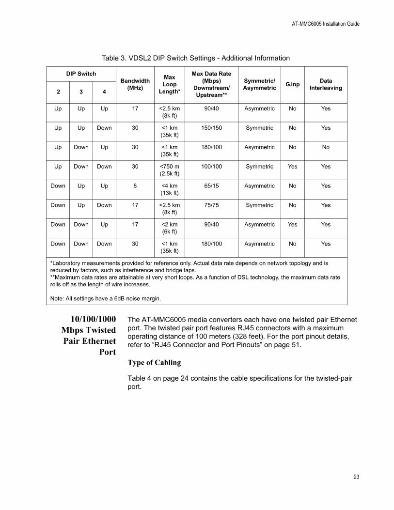
10/100/1000Mbps TwistedPair Ethernet
Port
The AT-MMC6005 media converters each have one twisted pair Ethernet port. The twisted pair port features RJ45 connectors with a maximum operating distance of 100 meters (328 feet). For the port pinout details, refer to “RJ45 Connector and Port Pinouts” on page 51.
Type of Cabling
Table 4 on page 24 contains the cable specifications for the twisted-pair port.
Table 3. VDSL2 DIP Switch Settings - Additional Information
DIP SwitchBandwidth
(MHz)
Max Loop
Length*
Max Data Rate (Mbps)
Downstream/Upstream**
Symmetric/Asymmetric
G.inpData
Interleaving2 3 4
Up Up Up 17 <2.5 km(8k ft)
90/40 Asymmetric No Yes
Up Up Down 30 <1 km(35k ft)
150/150 Symmetric No Yes
Up Down Up 30 <1 km(35k ft)
180/100 Asymmetric No No
Up Down Down 30 <750 m(2.5k ft)
100/100 Symmetric Yes Yes
Down Up Up 8 <4 km(13k ft)
65/15 Asymmetric No Yes
Down Up Down 17 <2.5 km(8k ft)
75/75 Symmetric No Yes
Down Down Up 17 <2 km(6k ft)
90/40 Asymmetric Yes Yes
Down Down Down 30 <1 km(35k ft)
180/100 Asymmetric No Yes
*Laboratory measurements provided for reference only. Actual data rate depends on network topology and is reduced by factors, such as interference and bridge taps.**Maximum data rates are attainable at very short loops. As a function of DSL technology, the maximum data rate rolls off as the length of wire increases.
Note: All settings have a 6dB noise margin.
23

Product Description
Auto MDI/MDI-X
An RJ45 twisted pair port on a 10/100/1000 Mbps Ethernet network device can have one of two possible wiring configurations: MDI or MDI-X. The RJ45 port on a PC, router, or bridge is typically wired as MDI, while the twisted pair port on a switch or hub is usually MDI-X.
The AT-MMC6005 media converters feature automatic MDI/MDI-X. Each port automatically determines the configuration of the port on the device to which it is connected and then configures itself appropriately. For example, if a port on a media converter is connected to a port on a bridge, which is typically wired as MDI, the port on the media converter automatically configures itself as MDI-X. This feature allows you to use either straight-through or crossover cables when connecting devices to the media converter.
Auto-Negotiation
The media converters Auto-Negotiate the speed and duplex mode of the Ethernet link, so that the link comes up in the highest performance configuration supported by both ends.
Table 4. Twisted-Pair Port Cabling Specifications
Speed Type of Cable
10 Mbps Standard TIA/EIA 568-B-compliant Category 3 or better shielded or unshielded cabling with 100 ohm impedance and a frequency of 16 MHz.
100 Mbps Standard TIA/EIA 568-A-compliant Category 5 or TIA/EIA 568-B-compliant Enhanced Category 5 (Cat 5e) shielded or unshielded cabling with 100 ohm impedance and a frequency of 100 MHz.
1000 Mbps Standard TIA/EIA 568-A-compliant Category 5 or TIA/EIA 568-B-compliant Enhanced Category 5 (Cat 5e) shielded or unshielded cabling with 100 ohm impedance and a frequency of 100 MHz.
24

AT-MMC6005 Installation Guide
Half- and Full-duplex Mode
Duplex mode refers to the way an end-node sends and receives data on the network. An end-node can operate in either half- or full-duplex mode, depending on its capabilities. An end-node that is operating in half-duplex mode can either send data or receive data, but it cannot do both at the same time. An end-node that is operating in full-duplex mode can send and receive data simultaneously. The best network performance is achieved when an end-node can operate at full-duplex, because the end-node is able to send and receive data simultaneously.
The AT-MMC6005 media converters can operate in either half- or full-duplex mode. The media converter can operate with end-nodes capable of either half-duplex or full-duplex, but only by using Auto-Negotiation to select the duplex mode; the AT-MMC6005 does not support forced duplex mode. It is important to remember that the two end-nodes connected to the ports on the media converters must be able to operate in the same duplex mode.
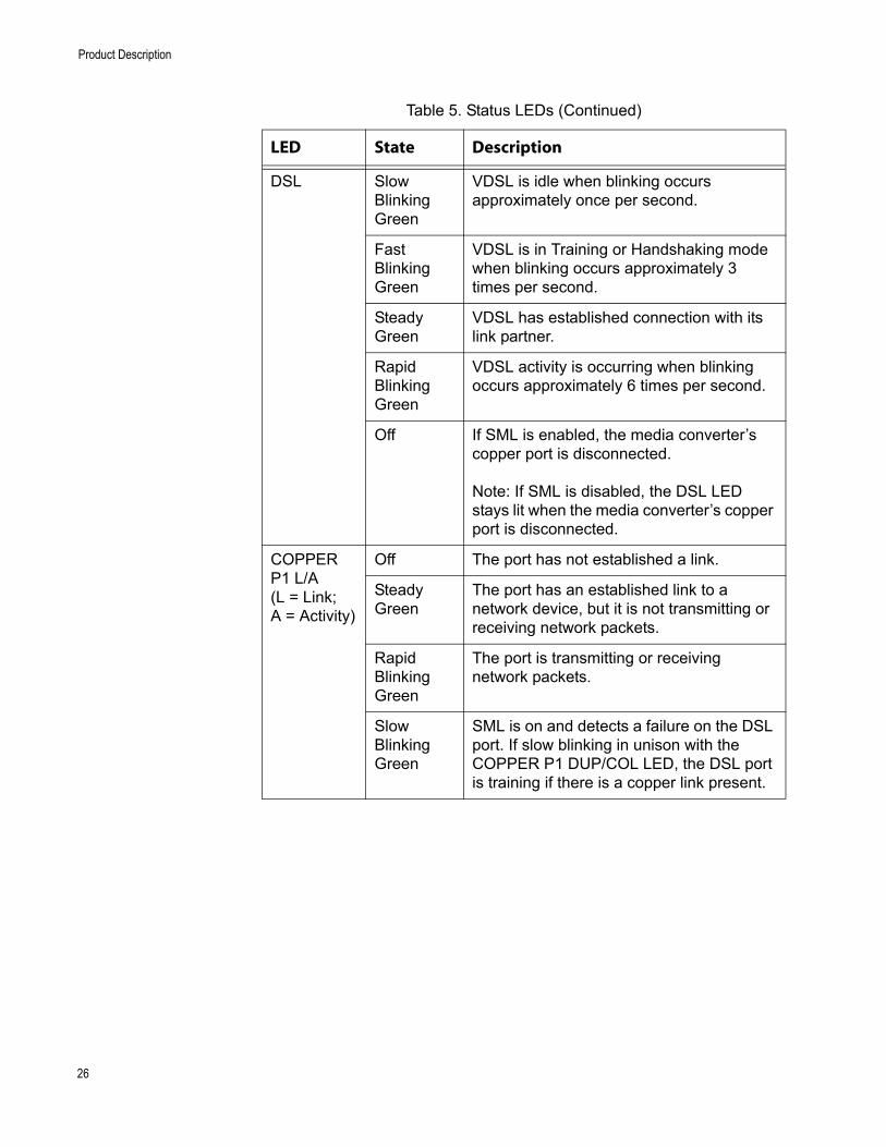
Status LEDs The AT-MMC6005 media converters feature the status LEDs defined in Table 5.
Table 5. Status LEDs
LED State Description
SYS Solid Green (with Heartbeat)
The media converter is receiving power.
Note: The SYS LED will flicker briefly at a regular interval. This “heartbeat” indicates that the internal system is running normally.
Off The media converter is not receiving power or an error is present on the media converter system.
25
Product Description
DSL Slow Blinking Green
VDSL is idle when blinking occurs approximately once per second.
Fast Blinking Green
VDSL is in Training or Handshaking mode when blinking occurs approximately 3 times per second.
Steady Green
VDSL has established connection with its link partner.
Rapid Blinking Green
VDSL activity is occurring when blinking occurs approximately 6 times per second.
Off If SML is enabled, the media converter’s copper port is disconnected.
Note: If SML is disabled, the DSL LED stays lit when the media converter’s copper port is disconnected.
COPPERP1 L/A(L = Link;A = Activity)
Off The port has not established a link.
Steady Green
The port has an established link to a network device, but it is not transmitting or receiving network packets.
Rapid Blinking Green
The port is transmitting or receiving network packets.
Slow Blinking Green
SML is on and detects a failure on the DSL port. If slow blinking in unison with the COPPER P1 DUP/COL LED, the DSL port is training if there is a copper link present.
Table 5. Status LEDs (Continued)
LED State Description
26

AT-MMC6005 Installation Guide
DIP Switches Use the DIP switches to configure the media converter as follows:
DIP switch 1 sets the media converter to Subscriber or Provider: Up (CPE) sets the media converter to Subscriber; Down (CO) sets the media converter to Provider. Figure 5 shows the media converter set to Subscriber.
Figure 5. AT-MMC6005 in Subscriber (Up/CPE) Position
DIP switches 2, 3, and 4 set the media converter VDSL profile settings. For VDSL settings, refer to Table 2 on page 22 and Table 3 on page 23.
NoteThe VDSL profile is only required to be set on the Provider unit: The VDSL profile is controlled by the Provider unit DIP switches, and the Subscriber unit ignores its own VDSL DIP switch settings.
DIP switch 5 turns SML on and off: UP enables SML; DOWN disables SML.
COPPER P1 DUP/COL
Off The port has not established a link or the link is in Half-Duplex mode.
Steady Green
The port has established a link in Full-Duplex mode.
Rapid Blinking Green
Collisions are occurring on the port.
Slow Blinking Green
SML is on and detects a failure on the DSL port. If slow blinking in unison with the COPPER P1 L/A LED, the DSL port is training if there is a copper link present.
Table 5. Status LEDs (Continued)
LED State Description
Subscriber(Up position)
27
Product Description
SmartMissingLink™
(SML)
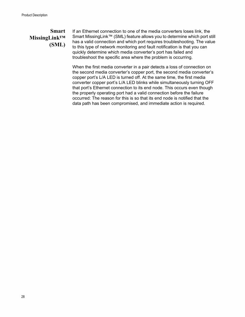
If an Ethernet connection to one of the media converters loses link, the Smart MissingLink™ (SML) feature allows you to determine which port still has a valid connection and which port requires troubleshooting. The value to this type of network monitoring and fault notification is that you can quickly determine which media converter’s port has failed and troubleshoot the specific area where the problem is occurring.
When the first media converter in a pair detects a loss of connection on the second media converter’s copper port, the second media converter’s copper port’s L/A LED is turned off. At the same time, the first media converter copper port’s L/A LED blinks while simultaneously turning OFF that port’s Ethernet connection to its end node. This occurs even though the properly operating port had a valid connection before the failure occurred: The reason for this is so that its end node is notified that the data path has been compromised, and immediate action is required.
28

AT-MMC6005 Installation Guide
For example, if the network connection to the Subscriber media converter’s copper port fails, the COPPER P1 L/A LED on the Provider media converter blinks slowly while its link is turned OFF. The COPPER P1 L/A LED on the Subscriber media converter is turned OFF, indicating a failed connection on the copper port. If the failure had started with the Provider media converter’s copper cabling (as shown in Figure 7), then the COPPER P1 L/A LED would blink slowly on the Subscriber media converter, and the COPPER P1 L/A LED on the Provider media converter would turn OFF.
SML Example Scenarios
Following are example scenarios with two SML enabled media converters connected back-to-back (bookend mode).
Figure 6 shows media converter and end node L/A LED behavior with SML enabled under normal conditions.
Figure 6. SML in Normal Condition with Two Media Converters
Figure 7 shows media converter and end node L/A LED behavior with SML enabled with a copper connection down between a media converter and an end node.
Figure 7. SML with Copper Connection to End Node Down
DSL Cable
End Node
Link LED On
End Node
Link LED On
AT-MMC6005
Copper L/ALED On DSL
Copper L/ALED On
Copper Cable Copper Cable
DSL
ProviderAT-MMC6005Subscriber
End Node
Link LED Off
End Node
Link LED OffCopper L/ALED Off
Copper L/ALED Blinking
DSL CableCopper Cable Copper Cable
DSL DSL
AT-MMC6005Provider
AT-MMC6005Subscriber
LED Off LED Blinking
29

Product Description
Enabling SML
To enable SML on the unit, set the SML ON/OFF DIP switch 5 on the rear panel of the unit to the ON (up) position. See Figure 8.
Figure 8. SML in ON Position
DC Power SupplyInput Port
The media converter has a single DC power supply socket on the back panel. The unit does not have a power switch. To turn the media converter ON or OFF, connect or disconnect the power cord.
External AC/DCPower Adapter
An external AC/DC power adapter is included with the media converter for desktop or wall-mount operation. The power adapter supplies 12VDC to the media converter. Allied Telesis supplies an approved safety compliant AC power adapter specifically designed for each region in which the media converter is sold. Each type of power adapter has a regulated output of 12VDC.
SML ON/OFF
30

Chapter 2
Installation
This chapter contains the installation procedures for the media converters. The installation process is described in the following sections:
“Installation Safety Precautions” on page 32
“Selecting a Site for the Media Converter” on page 34
“Cables Not Included” on page 35
“Unpacking the Media Converter” on page 36
“Installing the AT-MMC6005 Subscriber Unit” on page 37
“Installing the AT-MMC6005 Provider Unit” on page 43
31

Installation
Installation Safety Precautions
Please review the following safety precautions before you begin to install the media converters.
NoteThe indicates that a translation of the safety statement is available in a PDF document titled Translated Safety Statements on the Allied Telesis website at www.alliedtelesis.com/support.
WarningDo not work on this equipment or cables during periods of lightning activity. E2
CautionPower cord is used as a disconnection device. To de-energize equipment, disconnect the power cord. E3
CautionAir vents must not be blocked and must have free access to the room ambient air for cooling. E6
CautionOperating Temperature. This product is designed for a maximum ambient temperature of 40 degrees C. E7
CautionAll Countries: Install this product in accordance with local and national electric codes. E8
WarningAt ambient temperatures between 55 degrees C and 65 degrees C maximum, the product may have an elevated surface temperature that may exceed the Touch Temperature Limit of 70 degrees C. Please use caution when operating the product at these ambient temperatures. E83
32

AT-MMC6005 Installation Guide
WarningIn a domestic environment this product may cause radio interference in which case the user may be required to take adequate measures. E84
CautionOnly use the power adapter supplied with the device. E102
The following applies to the AT-MMC6005-E:
WarningThis equipment shall be installed in a Restricted Access location. E45
33
Installation
Selecting a Site for the Media Converter
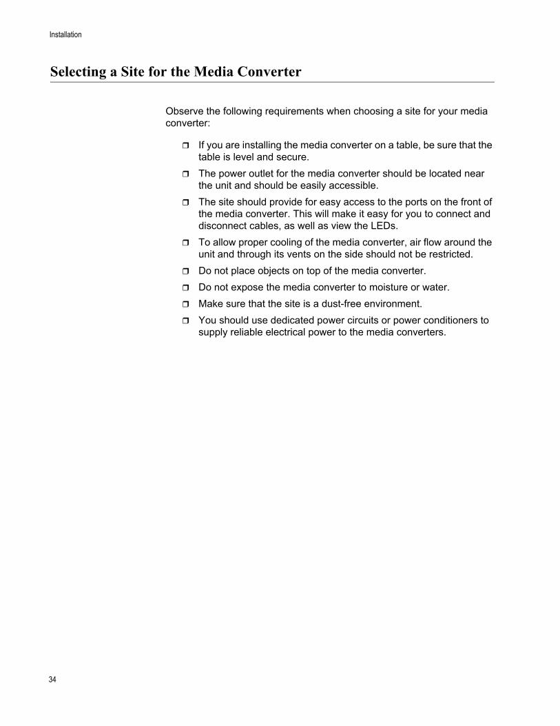
Observe the following requirements when choosing a site for your media converter:
If you are installing the media converter on a table, be sure that the table is level and secure.
The power outlet for the media converter should be located near the unit and should be easily accessible.
The site should provide for easy access to the ports on the front of the media converter. This will make it easy for you to connect and disconnect cables, as well as view the LEDs.
To allow proper cooling of the media converter, air flow around the unit and through its vents on the side should not be restricted.
Do not place objects on top of the media converter.
Do not expose the media converter to moisture or water.
Make sure that the site is a dust-free environment.
You should use dedicated power circuits or power conditioners to supply reliable electrical power to the media converters.
34

AT-MMC6005 Installation Guide
Cables Not Included
The AT-MMC6005 media converters require the cables described in Table 6. These cables are not included with the media converters.
Table 6. Cables
Port Cable Connector
Ethernet Category 5 or better 100-ohm unshielded straight-through or crossover twisted pair cable
RJ45
VDSL Line Standard telephone cable
RJ11
35

Installation
Unpacking the Media Converter
To unpack the media converter:
1. Remove all components from the shipping package and store the packaging material in a safe location.
NoteYou must use the original shipping material if you need to return the unit to Allied Telesis.
2. Place the media converter on a level, secure surface.
3. In addition to the media converter, verify that the shipping container includes the items shown in Figure 9.
Figure 9. Shipping Package Contents
Two wall brackets
Four bracket screws
One power adapter
(not provided - soldseparately)
(sold separately -included withwall brackets)
Four anchors(sold separately -included withwall brackets)
36

AT-MMC6005 Installation Guide
Installing the AT-MMC6005 Subscriber Unit
The AT-MMC6005 Subscriber unit will be used as a stand-alone device, and can be used as a desktop device, or mounted onto a wall, using the separately provided wall-mounting brackets and screws.
Using theSubscriber Unit
on a Desktop
To use the Subscriber unit on a desktop, perform the following procedure:
1. Place the Subscriber unit on a flat, secure surface (such as a desk or table), leaving ample space around the unit for ventilation.
2. Go to “Setting the DIP Switches” on page 40.
Wall-Mountingthe Subscriber
Unit
To install the Subscriber unit on a wall, perform the following procedure:
1. Place the Subscriber unit on a table.
2. Select a wall location for the unit.
3. Orient the brackets (separately-purchased) against the sides of the unit, as shown in Figure 10, and secure them to the unit with the four brackets screws included with the brackets.
Figure 10. Attaching the Brackets to Install the Media Converter on a Wall
4. Use a pencil or pen to mark the wall with the locations of the four holes in the brackets. The unit should be oriented as shown in Figure 11 on page 38.
37

Installation
Figure 11. Marking the Screw Hole Locations
5. Install four plastic anchors (included with separately purchased brackets) into the wall, at the locations marked in the previous step.
6. Secure the Subscriber unit to the wall using four wall-mounting screws (not provided). See Figure 12 on page 39.
Mark locations Mark locations
38

AT-MMC6005 Installation Guide
Figure 12. Securing the Media Converter to the Wall
7. Go to “Setting the DIP Switches” on page 40.
39

Installation
Setting the DIPSwitches
1. Set DIP switch 1 to the Up (CPE) position.
NoteThe VDSL profile is only required to be set on the Provider unit: The VDSL profile is controlled by the Provider unit DIP switches, and the Subscriber unit ignores its own VDSL DIP switch settings.
2. Set DIP switch 5 to the desired SML setting: the Up (ON) position enables SML; the Down (OFF) position disables SML.
3. Go to “Cabling the Subscriber Unit”.
Cabling theSubscriber Unit
To cable the Subscriber unit, perform the following steps:
1. Connect the Ethernet cable from the Ethernet port to the Ethernet port on the computer, as shown in Figure 13.
Figure 13. Ethernet to Computer
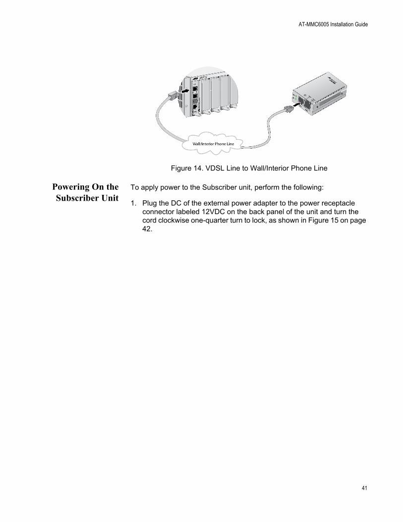
2. Connect a telephone line cable from the VDSL Line port to the wall/interior telephone line, as shown in Figure 14 on page 41, so that the Subscriber unit can communicate with the Provider unit.
40
AT-MMC6005 Installation Guide
Figure 14. VDSL Line to Wall/Interior Phone Line
Powering On theSubscriber Unit
To apply power to the Subscriber unit, perform the following:
1. Plug the DC of the external power adapter to the power receptacle connector labeled 12VDC on the back panel of the unit and turn the cord clockwise one-quarter turn to lock, as shown in Figure 15 on page 42.
41

Installation
Figure 15. Connecting 12VDC Powered Unit
2. Plug the power adapter to a power outlet. Refer to “Power Specifications” on page 50 for power requirements.
3. Verify that the SYS LED is solid green with a brief heartbeat blink. If the SYS LED is off, refer to “Troubleshooting” on page 47.
42
AT-MMC6005 Installation Guide
Installing the AT-MMC6005 Provider Unit
The AT-MMC6005 Provider unit can be installed as a desktop device, or mounted onto a wall using the separately provided wall-mounting brackets and screws.
The following applies to the AT-MMC6005-E:
WarningThis equipment shall be installed in a Restricted Access location. E45
Using theProvider Unit on
a Desktop
To use the Provider unit on a desktop, perform the following procedure:
1. Place the Provider unit on a flat, secure surface (such as a desk or table), leaving ample space around the unit for ventilation.
2. Go to “Setting the DIP Switches” on page 44.
Wall-Mountingthe Provider Unit
To install the Provider unit on a wall, perform the following procedure:
1. Place the Provider unit on a table.
2. Select a wall location for the unit.
3. Orient the brackets (separately-purchased) against the sides of the unit, as shown in Figure 10 on page 37, and secure them to the unit with the four brackets screws included with the brackets.
4. Use a pencil or pen to mark the wall with the locations of the four holes in the brackets. The unit should be oriented as shown in Figure 11 on page 38.
5. Install four plastic anchors (included with separately purchased brackets) into the wall, at the locations marked in the previous step.
6. Secure the Provider unit to the wall using four wall-mounting screws (not provided). See Figure 12 on page 39.
7. Go to “Setting the DIP Switches” on page 44.
43

Installation
Setting the DIPSwitches
1. Set DIP switch 1 to the Down (CO) position.
2. Set DIP switches 2, 3, and 4 to the desired VDSL settings: refer to Table 2 on page 22 and Table 3 on page 23.
3. Set DIP switch 5 to the desired SML setting: the Up (ON) position enables SML; the Down (OFF) position disables SML.
4. Go to “Cabling the Provider Unit”.
Cabling theProvider Unit
To cable the Provider unit, perform the following steps:
1. Connect the Ethernet cable from the Ethernet port to the Service Provider box in your wiring closet, as shown in Figure 16.
Figure 16. Ethernet to Internet Service Provider
2. Connect a telephone line cable from the VDSL Line port to the wall/interior telephone line, as shown in Figure 17, so that the Provider unit can communicate with the Subscriber unit.
Figure 17. VDSL Line to Wall/Interior Phone Line
MCR12
LINE
10Ba
seT/
100B
aseT
X
LINK AC
T
PWR
ERR
LINK
MG
MT
AT-
MC
603
VD
SL E
XTEN
DED
ETH
ERN
ET
PS
TN
InternetServiceProvider
44

AT-MMC6005 Installation Guide
Powering On theProvider Unit
To apply power to the Provider unit, perform the following:
1. Plug the DC of the external power adapter to the power receptacle connector labeled 12VDC on the back panel of the unit and turn the cord clockwise one-quarter turn to lock, as shown in Figure 15 on page 42.
2. Plug the power adapter to a power outlet. Refer to “Power Specifications” on page 50 for power requirements.
3. Verify that the SYS LED is solid green with a brief heartbeat blink. If the SYS LED is off, refer to “Troubleshooting” on page 47.
45

Installation
46
Chapter 3
Troubleshooting
This chapter contains information on how to troubleshoot the AT-MMC6005 media converters in the event a problem occurs.
NoteFor further assistance, please contact Allied Telesis Technical Support at www.alliedtelesis.com/support.
Problem 1: The SYS LED on the media converter is off.
Solutions: The unit is not receiving power. Try the following:
Verify that the power cord is securely connected to the power source and to the DC connector on the back panel of the media converter.
Verify that the power outlet has power by connecting another device to it.
Try using another power adapter of the same type that came with your media converter.
Verify that the voltage from the power source is within the required levels for your region.
Solution: An internal component on the unit is damaged or not working properly. Try power cycling the unit. If power cycling does not clear the fault, return the unit to Allied Telesis.
Problem 2: The twisted-pair port on the media converter is connected to an end node, but the port’s COPPER P1 L/A LED is off.
Solutions: The port is unable to establish a link to an end node. Try the following:
Verify that the end node connected to the twisted-pair port is powered on and is operating properly.
47

Troubleshooting
Verify that the twisted-pair cable is securely connected to the port on the media converter channel and to the port on the remote end-node.
Verify that the port is connected to the correct twisted-pair cable. This is to eliminate the possibility that the port is connected to the wrong end-node, such as a powered-off device.
Try connecting another end node to the twisted-pair port with a different cable. If the twisted-pair port is able to establish a link, then the problem is with the cable or the other end-node.
Verify that the twisted-pair cable does not exceed 100 meters (328 feet).
Verify that the end node connected to the media converter is set to Auto-Negotiate.
Verify that you are using the appropriate category of twisted-pair cable: Category 3 or better for 10 Mbps operation and Category 5 and Category 5E for 100 and 1000 Mbps operation.
NoteA 1000Base connection may require 5 to 10 seconds to establish a link.
Problem 3: Network performance between the twisted-pair port on the media converter and an end node is slow.
Solution: There might be a duplex mode mismatch between the port and the end node. This occurs when a twisted-pair port using Auto Negotiation is connected to a device with a fixed duplex mode of full duplex. If this is the cause of the problem, set the end node to Auto-Negotiate.
Problem 4: The DSL LED on the media converter is off.
Solutions: The DSL subsystem has stopped responding.
Power cycle the media converter.
Check the copper connection. The DSL LED will turn off if the local unit has SML enabled, and the copper connection is lost.
48

Appendix A
Technical Specifications
Below are the technical specifications for the media converters. The specification categories are as follows:
“Physical Specifications”
“Environmental Specifications”
“Power Specifications” on page 50
“Safety and Electromagnetic Emissions Certifications” on page 50
“RJ45 Connector and Port Pinouts” on page 51
Physical Specifications
Environmental Specifications
Table 8 lists environmental specifications for the AT-MMC6005.
Table 7. Physical Specifications
DimensionsW x D x H
50.8 mm x 99.1 mm x 20.3 mm (2.0 in x 3.9 in x 0.8 in)
Weight 0.2 kg (0.4 lb)
Table 8. Environmental Specifications - AT-MMC6005
Operating Temperature 0° C to 50° C (32° F to 122° F)
Storage Temperature -30° C to 70° C (-22° F to 158° F)
Operating Humidity 5% to 90% non-condensing
Storage Humidity 5% to 95% non-condensing
Operating Altitude Range Up to 3,000 m (9,843 ft)
49

Technical Specifications
Table 9 lists environmental specifications for the AT-MMC6005-E.
Power Specifications
The following specifications apply to the DC power connector on the media converter.
Safety and Electromagnetic Emissions Certifications
Table 9. Environmental Specifications - AT-MMC6005-E
Operating Temperature -20° C to 65° C (-4° F to 149° F)
Storage Temperature -40° C to 80° C (-40° F to 176° F)
Operating Humidity 5% to 90% non-condensing
Storage Humidity 5% to 95% non-condensing
Operating Altitude Range Up to 3,000 m (9,843 ft)
Table 10. Power Specifications
Input supply voltage 12 VDC
Input current (typical) 200 mA
Input current (maximum) 500 mA
Table 11. Safety and Electromagnetic Emissions Certifications
Safety UL60950-1, EN60950-1
Emissions (EMI)FCC Class A, CISPR 22 Class A, EN55022 Class A, RCM,VCCI Class A
ImmunityEN55024, EN61000-3-2, EN61000-3-3
Environmental ComplianceEU-RoHS compliant, WEEEChina RoHS compliant
50

AT-MMC6005 Installation Guide
RJ45 Connector and Port Pinouts
Figure 18 illustrates the pin layout for the RJ45 connector and port.
Figure 18. RJ45 Connector and Port Pin Layout
Table 12 lists the pin signals when a port is operating in the MDI configuration at 10 or 100 Mbps.
Table 13 lists the pin signals when a port is operating in the MDI-X configuration at 10 or 100 Mbps.
Table 12. MDI Pin Signals (10 or 100 Mbps)
Pin Signal
1 TX+
2 TX-
3 RX+
6 RX-
Table 13. MDI-X Pin Signals (10 or 100 Mbps)
Pin Signal
1 RX+
2 RX-
3 TX+
6 TX-
51

Technical Specifications
Table 14 lists the pin signals when a port is operating at 1000 Mbps.
Table 14. Pin Signals (1000 Mbps)
Pin Pair Signal
1 1 TX and RX+
2 1 TX and RX-
3 2 TX and RX+
4 3 TX and RX+
5 3 TX and RX-
6 2 TX and RX-
7 4 TX and RX+
8 4 TX and RX-
52