astronomy and field-aligned magnetohydrodynamic bow shock flows...
TRANSCRIPT

Astron. Astrophys. 343, 641–649 (1999) ASTRONOMYAND
ASTROPHYSICS
Field-aligned magnetohydrodynamic bow shock flowsin the switch-on regime
Parameter study of the flow around a cylinderand results for the axi-symmetrical flow over a sphere
H. De Sterck? and S. Poedts??
Center for Plasma Astrophysics, Katholieke Universiteit Leuven, Celestijnenlaan 200B, B-3001 Heverlee, Belgium([email protected]; [email protected])
Received 30 September 1998 / Accepted 6 November 1998
Abstract. A parameter study is undertaken for steady sym-metrical planar field-aligned MHD bow shock flows around aperfectly conducting cylinder. For sets of values of the inflowplasmaβ and Alfvenic Mach number (MA) which allow forswitch-on shocks, a numerical solution is obtained which ex-hibits a complex bow shock shape and topology with multipleshock fronts and a dimpled leading front. For parameter val-ues outside the switch-on domain, a classical single-front bowshock flow is obtained. These results show that theβ andMA
parameter regime for which the complex bow shock topologyoccurs, corresponds closely to the parameter regime for whichswitch-on shocks are possible.
The axi-symmetrical field-aligned bow shock flow over aperfectly conducting sphere is then calculated for one set ofvalues forβ andMA in the switch-on domain, resulting in acomplex bow shock topology similar to the topology of theflow around a cylinder.
These complex shock shapes and topologies may be en-countered in low-β space plasmas. Fast coronal mass ejectionsmoving away from the sun in the low-β inner corona mayinduce preceding shock fronts with upstream parameters inthe switch-on domain. Planetary and cometary bow shocksmay have upstream parameters in the switch-on domain whenthe impinging solar wind occasionally becomes low-β. Thesimulation results may be important for phenomena in theEarth’s magnetosheath.
Key words: Magnetohydrodynamics (MHD) – shock waves –methods: numerical – Sun: corona – comets: general – planetsand satellites: general
Send offprint requests to: H. De Sterck? Research Assistant of the Fund for Scientific Research – Flanders
(Belgium). Also at the High Altitude Observatory, National Center forAtmospheric Research, Boulder, CO, USA?? Research Associate of the Fund for Scientific Research – Flanders
(Belgium)
1. Introduction
Shock phenomena are abundant in space physics plasmas.Large-scale flows involving shocks are often modeled as ‘con-tinuous fluids’ and described by the equations of hydrodynamicsand magnetohydrodynamics (MHD) (e.g. Petrinec & Russell1997). Bow shocks are formed when the solar wind encoun-ters comets (e.g. Gombosi et al. 1994, 1996) and planets (e.g.Wu 1992, Tanaka 1993, Song & Russell 1997). Shocks playan important role in the magnetic topology of the heliospherewhich interacts with the interstellar wind (e.g. Pogorelov 1995,Pogorelov & Semenov 1997, Linde et al. 1998, Ratkiewicz etal. 1998). Helios 1 spacecraft observations have detected in-terplanetary shocks which are well correlated with fast solarcoronal mass ejections (CMEs) observed by the Solwind coron-agraph (Sheeley et al. 1985), and some bright features present inSMM coronagraph images have been interpreted as signaturesof shocks induced by fast CMEs (Steinolfson & Hundhausen1990a, 1990c, Hundhausen 1998).
Hydrodynamic bow shocks around a cylindrical object havethe classical form and topology of Fig. 1a, with a single shockfront which is concave-inward (to the object). Most MHD bowshocks described in the space physics literature have the samesimple shape and topology, but recent numerical simulation re-sults have revealed a MHD bow shock flow which exhibits amore complex shape and topology, for the case of a low in-flow plasmaβ and an inflow Alfvenic Mach numberMA whichcorresponds to moderately super-Alfvenic flow. De Sterck etal. (1998b) study the steady state planar (Bz ≡ 0 andvz ≡ 0)field-aligned bow shock flow with top–bottom symmetry arounda perfectly conducting cylinder for one set of parameters in thisparameter domain. They describe a steady state bow shock flowwhich exhibits a complex multiple-front shape and topology.The bow shock solution is shown in Fig. 2, and the topology ofthe flow is sketched in Fig. 1b. The leading shock front contains aconcave-outward ‘dimple’, and is followed by several other dis-continuities. The ‘dimpling’ of shock fronts in a low-β plasmahad been observed earlier in time-dependent numerical simula-tions of CMEs moving faster than the Alfven speed, and dimpled

642 H. De Sterck & S. Poedts: MHD bow shocks in the switch-on regime
b
θ
A
D G
HE
F I
θB
C
a
Fig. 1a and b.Possible bow shock topologies for a 2D uniform flow(streamlines have arrows) falling in on a cylinder from the left. Shocknormals are shown as thin dashed lines.a Traditional single-front bowshock topology.b Complex multiple-front bow shock topology whichappears for the field-aligned MHD bow shock flow of Fig. 2 with pa-rameters in the switch-on domain.
-0.250 -0.175 -0.100x
0.000
0.125
0.250
y
-0.250 -0.175 -0.1000.000
0.125
0.250
Fig. 2. Part of the steady bow shock solution for one set of inflowparameters in the switch-on domain obtained in De Sterck et al. (1998b)(inflow Mach numberMA = 1.5 and inflow plasmaβ = 0.4, 120×120 grid). We show density contours (piling up in the shocks) andmagnetic field lines (coming in horizontally on the left). The flowcomes in from the left. The cylinder is situated on the right (thicksolid). The leading shock front is slightly dimpled. In the central partof the flow, a second front has separated and is trailing the leadingfront. Additional discontinuities can be seen in the central interactionregion. The topology of the flow is sketched in Fig. 1b. The shocks arefast, hydrodynamic, and intermediate, as discussed in Sect. 2.1.
bright features in coronagraph images have been related to dim-pled shock fronts preceding super-Alfvenic CMEs (Steinolfson& Hundhausen 1990a, 1990c, Hundhausen 1998). These effectshave to be clearly separated from the observed concave-outwardshapes of someslow (sub-Alfvenic) CME fronts, which havebeen related to the geometrical properties ofslowMHD shocks(Steinolfson & Hundhausen 1990b). In this paper we discuss thegeometrical shapes offast(super-Alfvenic) MHD bow shocks.
Theoretical reasoning based on symmetry considerationshas proposed the possible occurrence of fast switch-on shocksin a parameter regime which is called the switch-on regime, asan explanation for the occurrence of multiple-front MHD bowshocks and the dimpling of the leading shock front of fast CMEs(Steinolfson & Hundhausen 1990a, 1990c, Hundhausen 1998,De Sterck et al. 1998b). This line of thought will be clarified inSect. 2.1. This reasoning predicts complex bow shock topolo-gies for all bow shock flows with parameters in the switch-onregime. In the present paper we will verify this prediction.
In the present paper we extend the numerical results of DeSterck et al. (1998b) on MHD bow shock topology in the switch-on regime in two ways. In Sect. 3 we carry out a detailed pa-rameter study of symmetrical planar (Bz ≡ 0 and vz ≡ 0)field-aligned bow shock flows around a cylinder. We study howthe shape and topology of the bow shock solution which was ob-tained by De Sterck et al. (1998b) for one particular set of param-eters within the switch-on domain, changes when parametersare varied within the switch-on domain and when parametersare taken outside the switch-on domain. In Sect. 4 we presentresults for the axi-symmetrical field-aligned bow shock flowover a perfectly conducting sphere for a set of parameters in theswitch-on domain. The presentation of these results is precededby a short discussion in Sect. 2 of the properties of MHD shocksand the switch-on regime, and a discussion of the numerical so-lution technique. Finally, our conclusions are formulated anddiscussed in Sect. 5.
These extended results on MHD bow shock flows in theswitch-on regime, together with the detailed discussion ofone example of a complex bow shock flow in De Sterck etal. (1998b), form an extension of the general theory and phe-nomenology of MHD bow shock flows, with possible applica-tions in space physics (Petrinec & Russell 1997).
2. Properties of MHD shocks and numerical solutionof the MHD equations
2.1. Properties of MHD shocks
The complex topology of bow shock flows in the switch-onregime can be understood in terms of the properties of MHDshocks. This will be explained in the present section. Contraryto the hydrodynamic equations, which allow for only one wavemode, the MHD equations allow for three distinct wave modes,the fast magneto-acoustic wave, the Alfven wave, and the slowmagneto-acoustic wave, with (positive) anisotropic wave speedssatisfyingcf ≥ cA ≥ cs in standard notation. Three types ofshocks are described by the MHD equations, connecting plasmastates which are traditionally labeled from1 to 4, with state 1a super-fast state, state 2 sub-fast but super-Alfvenic, state 3sub-Alfvenic but super-slow, and state 4 sub-slow (Landau &Lifshitz 1984, Anderson 1963, De Sterck et al. 1998b). Fast 1–2 MHD shocks refract the magnetic field away from the shocknormal. Intermediate MHD shocks (1–3, 1–4, 2–3, and 2–4)change the sign of the component of the magnetic field which istangential to the shock front, and thus flip magnetic field linesover the shock normal. A special case of a 1–4 intermediate

H. De Sterck & S. Poedts: MHD bow shocks in the switch-on regime 643
shock is a 1–4 hydrodynamic (intermediate) shock, for whichthe magnetic field is perpendicular to the shock and does notchange through the shock. Slow 3–4 MHD shocks refract themagnetic field towards the shock normal.
In De Sterck et al. (1998b) the types of the discontinuitiesthat are present in the complex bow shock flow of Fig. 2 areclearly identified. The results of this detailed analysis can besummarized as follows, using the lettering labels of Fig. 1b.Shock parts A–B and D–E are 1–2 fast shocks, E–F is a 1–4hydrodynamic shock, and B–C–D is a 1–3 intermediate shock.E–G is a 1=2–3=4 intermediate shock. D–G–H–I is a 2–4 in-termediate shock. E–H is a tangential discontinuity. Other tan-gential discontinuities stretch out from points G and H alongthe streamlines to infinity. The reader can verify in Fig. 2 thatall the intermediate shocks indeed flip magnetic field lines overthe shock normal.
We remark here that the presence of intermediate shocks inthis flow is an important illustration in two dimensions (2D) ofmany of the new theoretical results on the existence of interme-diate shocks (Wu 1991, Freistuehler & Szmolyan 1995, Myong& Roe 1997). We refer to De Sterck et al. (1998b) for a dis-cussion of this subject. Analysis of this stationary flow in termsof steady state characteristic curves and elliptic and hyperbolicregions, shows that this flow contains a steady state analog ofanxt MHD compound shock (Brio & Wu 1988, Myong & Roe1997), which is a manifestation of the non-convex nature of theMHD equations (De Sterck, Low, & Poedts, submitted toPhys.Plasmas). It is important to note that there is still discussionabout the stability of intermediate shocks against non-planarperturbations (Wu 1991, Barmin et al. 1996), and it will be in-teresting to see how the intermediate shocks present in our 2Dplanar simulation results, would survive in a three-dimensional(3D) context which allows for non-planar perturbations. Thisremains subject of further work.
A fast switch-on shock is a limiting case of the fast shockfor which the upstream magnetic field direction coincides withthe direction of the shock normal, and the downstream magneticfield makes a finite angleθ with the shock normal. The down-stream normal plasma speed exactly equals the downstream nor-mal Alfven speed in the shock frame. The component of themagnetic field parallel to the shock surface is thus effectively‘switched on’ in going from the upstream to the downstreamstate of the shock. The shock at point B in Fig. 1b is an exampleof a fast switch-on shock. From the MHD Rankine-Hugoniot re-lations one can derive (Kennel et al. 1989) that switch-on shockscan be encountered for upstream parameters satisfying
β < 2/γ, (1)
and
1 < MA <
√γ(1 − β) + 1
γ − 1, (2)
with β = 2p/B2 the plasmaβ, and the Alfvenic Mach numbergiven byMA = v/cA, wherev is the plasma velocity andcA
the Alfven speed along the shock normal. Forγ = 5/3, the
0.0 0.2 0.4 0.6 0.8 1.0 1.2 1.4β
0.51.0
1.5
2.0
2.5
MA
Fig. 3. Parameter domain for which switch-on shocks are possible. Forγ = 5/3, switch-on shocks are possible for upstream values ofβ andMA located in the shaded region. In Sect. 3, numerically obtained bowshock flows are presented for inflow quantities with fixedβ = 0.4 andMA varying from 1.1 to 1.9 (the diamonds on the vertical line), andwith fixed MA = 1.5 andβ varying from 0.1 to 0.9 (the triangles onthe horizontal line).
parameter domain in theβ − MA plane for which switch-onshocks can occur, is sketched in Fig. 3.
These properties of MHD shocks allow us to understandwhy the classical single shock front solution of Fig. 1a is notfound for MHD bow shocks in the switch-on regime. Becauseof symmetry, the magnetic field line which coincides with thestagnation streamline (stretching horizontally from infinity tothe stagnation point (v = 0) at the cylinder) has to be a straightline. In other words, on this line, the field is not deflected by theshock. Away from this line along the shock front, the shock hasto be a fast MHD shock, with the field refracted away from thenormal (Fig. 1a) in order to have the post-shock flowing plasmadrape around the cylinder. As we move along this fast shockfront closer and closer to the intersection of the front with thestagnation line, the upstream tangential component of the mag-netic field goes to zero. But when the upstream parameters lie inthe switch-on domain, the downstream tangential component ofthe magnetic field does not vanish as we approach this intersec-tion point, resulting in a switch-on shock with a finite turningangleθ, as illustrated in Fig. 1a. Clearly, approaching the stag-nation line from its two sides along the fast shock front, wouldlead to two switch-on shocks of opposite deflection. This meansthat there is a discontinuity between the two physical states onthe two sides of the stagnation field line. Such a discontinuityis not physically justified, so the concave-inward shock geom-etry (as in Fig. 1a) needs to be modified in order to avoid thisdiscontinuity. In the present paper it is studied how nature ac-complishes this, i.e. what alternatives to the concave-inwardshock geometry the flow finds to get around the object and howthis alternative depends on the parameters that characterize theflow, viz. the plasma betaβ and the Alfvenic Mach numberMA.
2.2. Numerical solution of the MHD equations
In Sect. 3, we will present numerically obtained bow shock flowsaround a cylinder for various parameter sets inside and outsidethe switch-on domain, to investigate closely the correspondencebetween the complex bow shock topology as it was obtained inDe Sterck et al. (1998b), and the parameter domain in whichswitch-on shocks can occur. In Sect. 4, we will investigate theaxi-symmetrical bow shock flow over a sphere. In the present

644 H. De Sterck & S. Poedts: MHD bow shocks in the switch-on regime
section we will briefly describe the numerical solution techniqueused.
In our simulations a uniform field-aligned flow in planarsymmetry (Sect. 3;xyz system with∂/∂z = 0, andBz ≡ 0 andvz ≡ 0) or axial symmetry (Sect. 4;xrφ system with∂/∂φ = 0,andBφ ≡ 0 andvφ ≡ 0) enters from the left and encounters aperfectly conducting rigid cylinder (Sect. 3) or sphere (Sect. 4).The magnetic field is aligned with the plasma velocity in thewhole domain of the resulting stationary ideal MHD flow. Thestationary bow shock flow is completely determined by the in-flow β andMA in the direction of the flow speed. We take thex axis horizontal, and we can freely chooseρ = 1 andBx = 1(implying that the Alfven speed along the field linescA = 1).The pressure and velocity can then be determined fromβ andMA. Finally, we takeBy = 0 (Br = 0) andvy = 0 (vr = 0).As the resulting stationary ideal MHD flow is scale invariant,we can freely choose the radius of the cylinder (sphere). Wetaker = 0.125 and the cylinder (sphere) is placed at the originof the coordinate system. We simulate the flow in the upper leftquadrant, on a stretched elliptic polar-like structured grid. Weimpose the above described uniform flow as the initial condi-tion. We use ghost cells to specify the boundary conditions. Onthe left, we impose the uniform superfast incoming flow. Theobstructing object is perfectly conducting. We look for a sta-tionary flow solution with top–bottom symmetry, such that thehorizontal line which extends to the center of the cylinder is thestagnation line, parallel to the incoming flow (Fig. 1). This sym-metry has to be imposed in the boundary condition on the lowerborder of the simulation domain in order to obtain a stationarysymmetrical solution. The right outflow condition is superfast,so there we extrapolate all quantities to the ghost cells. Theflow evolves in time until a converged steady state bow shocksolution is obtained.
We solve the equations of ideal one-fluid MHD. In ‘conser-vative form’ these equations are given by
∂
∂t
ρρ vBe
+ ∇ ·
ρ vρ vv + I (p + B · B /2) − BB
vB − Bv(e + p + B · B /2)v − (v · B)B
= −
0Bv
v · B
∇ · B. (3)
This set of equations has to be supplemented with the divergencefree condition∇ · B = 0 as an initial condition. Hereρ andpare the plasma density and pressure respectively,v is the plasmavelocity,B the magnetic field, and
e =p
γ − 1+ ρ
v · v
2+
B · B
2, (4)
is the total energy density of the plasma.I is the unity matrix.The magnetic permeabilityµ = 1 in our units. These equationsdescribe the conservation of mass, momentum, magnetic field,and energy.
As proposed by Powell et al. (1995), we have put a sourceterm proportional to∇·B in the right hand side (RHS) of Eq. 3.Discretization of this form of the equations results in a numericalscheme which conserves the∇ · B = 0 constraint up to a dis-cretization error. This approach is an attractive alternative to theuse of an extra artificial∇ · B correction in every time step ob-tained via solution of an elliptic equation, because it consumesless computing time and because it cures the∇·B problems ina way which is more in harmony with the hyperbolicity of theMHD system.
We solve Eq. 3 using a conservative finite volume high reso-lution Godunov shock capturing scheme which is second orderin space and time, employing a slope-limiter approach (Leveque1992, Gombosi et al. 1994, Toth & Odstrcil 1996, Linde et al.1998) with minmod-limiting on the slopes of the primitive vari-ables. The time-integration is explicit with a two-step Runge-Kutta method. The code was previously used for MHD simula-tions of interacting hot filaments in a tokamak (De Sterck et al.1998a). For our present simulations, we use the Lax-Friedrichsnumerical flux function (Leveque 1992, Toth & Odstrcil 1996,Barmin et al. 1996), which is simple and robust. Contact andtangential discontinuities are not perfectly well resolved due tothe relatively high numerical dissipation for these waves, butshocks are well resolved in steady state calculations. We did notuse Roe’s scheme (Roe & Balsara 1996) although this scheme intheory could resolve shocks and, especially, tangential discon-tinuities much better. We have found several problems whiletrying to apply this scheme to our simulation. Roe’s schemesuffers from various instabilities, like the carbuncle-instability(Quirk 1994), and as a result of these numerical instabilities,steady state solutions could not be obtained with this scheme.Using the Lax-Friedrichs scheme, we obtained convergence ofmore than eight orders of magnitude in the norm of the den-sity residual. We can remark that the code sometimes generatessmall spurious oscillations in the upstream part of the flow, ascan be seen in Fig. 2. Such oscillations seem to be hard to avoidwith shock-capturing numerical schemes, but fortunately theyare very small.
The bow shock flow of Fig. 2 constitutes an interesting newtest case for ideal MHD codes, because it is a well-defined prob-lem with a simple set-up but with a wealth of MHD shocks anddiscontinuities in the resulting flow.
3. Parameter study of the flow around a cylinder
In this section we present numerical simulation results for sym-metrical bow shock flows around a cylinder, for the values ofthe parametersβ andMA which are indicated by the trianglesand diamonds in Fig. 3.
In Fig. 4 we show global views of the bow shock solutionsfor a fixedβ = 0.4 andMA varying from 1.1 to 1.9. It followsfrom Eq. 2 that the critical Alfvenic Mach number under whichswitch-on shocks can exist isMA = 1.732. For inflow speedsmuch faster than the Alfven speed (cA = 1), the bow shock hasthe traditional single-front topology that is also encounteredin hydrodynamic bow shocks. If the inflow speed drops below

H. De Sterck & S. Poedts: MHD bow shocks in the switch-on regime 645
vx=1.1
vx=1.2
vx=1.3
vx=1.4
vx=1.5
vx=1.6
vx=1.7
vx=1.8
vx=1.9
Fig. 4. Stationary bow shock solutions forfixedβ = 0.4 and for varying inflow speeds(80 × 80 grids, x ∈ [−0.35, 0], y ∈[−2, 2]). Density contours pile up in shocks,and streamlines come in horizontally fromthe left. For inflow speeds much faster thanthe Alfven speed (cA = 1), the bow shockhas the traditional single-front topology thatis also encountered in hydrodynamic bowshocks. If the inflow speed drops below1.732 however, a concave-outward dimpleforms in the leading shock front and a sec-ond shock front appears.
1.732 however, a concave-outward dimple forms in the leadingshock front and a second shock front appears. This change inshape and topology of the bow shock flow thus happens whenthe inflow speed becomes lower than the critical speed underwhich switch-on shocks are possible.
In Fig. 5 we show a detailed representation of the flow nearthe stagnation streamline for the bow shock solutions with vary-ing inflow speed of Fig. 4. For inflow velocities below the criticalswitch-on value for the inflow speed (MA < 1.732), the lead-ing shock front has a dimpled shape. The dimpling becomesmuch more pronounced as the inflow velocity decreases. Belowthe critical inflow speed, a second shock front appears whichtrails the leading shock front, and additional discontinuities arepresent between the two shock fronts. All the shocks and dis-continuities present in the topology sketch of Fig. 1b seem tobe present in all the flows. Inspection of the way in which thefield lines are refracted when they pass the shocks, reveals thatthe shocks in all the flows are of the same type as the shocksin the model flow of Fig. 2 which were discussed in Sect. 2.1,and this conclusion is confirmed by detailed analysis of up-stream and downstream Mach numbers, along the lines of thedetailed analysis in De Sterck et al. (1998b). For smaller inflowvelocities, the central interaction region becomes smaller andthe leading shocks become weaker while the trailing shock be-comes stronger. As a consequence, the shock E–G of Fig. 1bcan not be identified for the flow withvx = 1.1 with the resolu-tion of Fig. 5. More detailed simulations and plots (not shown)
do, however, show that shock E–G is present also for the flowwith vx = 1.1. For inflow velocityvx = 1.7, close to the criti-cal velocity ofvx = 1.732, the secondary shock fronts becomeweak and shock E–G can hardly be identified with the resolu-tion of Fig. 5. Forvx = 1.8 the secondary (stationary) waves arestill present, but they are not steepened into shocks any more.The secondary waves have disappeared almost completely forvx = 1.9, and the simple single-front bow shock topology ofFig. 1a is recovered. We can thus conclude that for all the flowswith parameters in the switch-on domain (1 < MA < 1.732),the topology of Fig. 1b is recovered. The shapes, sizes and shockstrengths of the shock parts present in the topology of Fig. 1b,vary whenMA is varied within the switch-on region. The dim-ple effect is more pronounced for smaller inflow Alfvenic MachnumberMA.
Above we discussed how the flow manages to go aroundthe obstructing cylinder by adjusting the bow shock shape andtopology to the inflow Alfvenic Mach number. Hereby theplasmaβ value was fixed to 0.4. Below we fix the inflowAlfv enic Mach number and verify how the flow modifies thegeometrical structure of the bow shock when the value of theplasmaβ is varied.
In Fig. 6 we show global views of the bow shock solutions fora fixedMA = 1.5 andβ varying from 0.1 to 0.9. It follows fromEq. 2 that the critical plasmaβ under which switch-on shockscan exist isβ = 0.7. For plasmaβ values larger than the criticalvalue ofβ = 0.7, the bow shock has the traditional single-front

646 H. De Sterck & S. Poedts: MHD bow shocks in the switch-on regime
-0.250 -0.125-0.10
-0.05
0.00
0.05
0.10vx=1.1
-0.250 -0.125-0.10
-0.05
0.00
0.05
0.10
-0.250 -0.125-0.10
-0.05
0.00
0.05
0.10vx=1.2
-0.250 -0.125-0.10
-0.05
0.00
0.05
0.10
-0.250 -0.125-0.10
-0.05
0.00
0.05
0.10vx=1.3
-0.250 -0.125-0.10
-0.05
0.00
0.05
0.10
-0.250 -0.125-0.10
-0.05
0.00
0.05
0.10vx=1.4
-0.250 -0.125-0.10
-0.05
0.00
0.05
0.10
-0.250 -0.125-0.10
-0.05
0.00
0.05
0.10vx=1.5
-0.250 -0.125-0.10
-0.05
0.00
0.05
0.10
-0.250 -0.125-0.10
-0.05
0.00
0.05
0.10vx=1.6
-0.250 -0.125-0.10
-0.05
0.00
0.05
0.10
-0.250 -0.125-0.10
-0.05
0.00
0.05
0.10vx=1.7
-0.250 -0.125-0.10
-0.05
0.00
0.05
0.10
-0.250 -0.125-0.10
-0.05
0.00
0.05
0.10vx=1.8
-0.250 -0.125-0.10
-0.05
0.00
0.05
0.10
-0.250 -0.125-0.10
-0.05
0.00
0.05
0.10vx=1.9
-0.250 -0.125-0.10
-0.05
0.00
0.05
0.10
Fig. 5. Detailed representation of the flownear the stagnation streamline for the bowshock solutions with varying inflow speedand fixedβ = 0.4 (80 × 80 grids). Densitycontours pile up in shocks, and streamlinescome in horizontally from the left. Under thecritical switch-on value for the inflow speed,the leading shock front dimples and a sec-ond shock front appears. Additional discon-tinuities can be seen between the two shockfronts.
topology that is also encountered in hydrodynamic bow shocks.If the plasmaβ drops below0.7 however, a concave-outwarddimple forms in the leading shock front and a second shockfront appears. This second shock front thus appears when theplasmaβ becomes lower than the critical plasmaβ under whichswitch-on shocks are possible.
In Fig. 7 we show a detailed representation of the flow nearthe stagnation streamline for the bow shock solutions with vary-ing plasmaβ of Fig. 6. For plasmaβ values below the criticalswitch-on value for the plasmaβ (β < 0.7), the leading shockfront has a dimpled shape. The dimpling becomes more pro-nounced as the plasmaβ is decreased. Below the critical plasmaβ, a second shock front appears which trails the leading shockfront, and additional discontinuities are present between the twoshock fronts. All the shocks and discontinuities present in thetopology sketch of Fig. 1b seem to be present in all the flows.Inspection of the way in which the field lines are refracted whenthe shocks are passed, reveals that the shocks in all the flows
are of the same type as the shocks in the model flow of Fig. 2which were discussed in Sect. 2.1, and this conclusion is con-firmed by detailed analysis of upstream and downstream Machnumbers, along the lines of the detailed analysis in De Sterck etal. (1998b). For smaller plasmaβ values, the central interactionregion in front of the cylinder becomes smaller. As a conse-quence, the shock E–G of Fig. 1b can not be identified for theflow with β = 0.1 with the resolution of Fig. 7. More detailedplots (not shown) do, however, show that shock E–G is presentalso for the flow withβ = 0.1. For plasmaβ = 0.7, which is thecritical value, the secondary (stationary) wave has only nearlysteepened into a shock. Shock E–G can not be identified forthis critical value of the parameters. Forβ = 0.8 the secondarywaves are still present, but they have not steepened into shocksany more. The secondary waves are even weaker forβ = 0.9,and the simple single-front bow shock topology of Fig. 1a isrecovered. We can thus conclude that for all the flows with pa-rameter values in the switch-on domain (β < 0.7), the topology

H. De Sterck & S. Poedts: MHD bow shocks in the switch-on regime 647
β=0.1
β=0.2
β=0.3
β=0.4
β=0.5
β=0.6
β=0.7
β=0.8
β=0.9
Fig. 6. Stationary bow shock solutions forfixed MA = 1.5 and for varying plasmaβ (80 × 80 grids, x ∈ [−0.35, 0], y ∈[−1.4, 1.4]). Density contours pile up inshocks, and streamlines come in horizon-tally from the left. For plasmaβ values largerthan the critical value ofβ = 0.7, the bowshock has the traditional single-front topol-ogy that is also encountered in hydrody-namic bow shocks. If the plasmaβ dropsbelow0.7 however, a concave-outward dim-ple forms in the leading shock front and asecond shock front appears.
-0.350 -0.125-0.10
-0.05
0.00
0.05
0.10β=0.1
-0.350 -0.125-0.10
-0.05
0.00
0.05
0.10
-0.350 -0.125-0.10
-0.05
0.00
0.05
0.10β=0.2
-0.350 -0.125-0.10
-0.05
0.00
0.05
0.10
-0.350 -0.125-0.10
-0.05
0.00
0.05
0.10β=0.3
-0.350 -0.125-0.10
-0.05
0.00
0.05
0.10
-0.350 -0.125-0.10
-0.05
0.00
0.05
0.10β=0.4
-0.350 -0.125-0.10
-0.05
0.00
0.05
0.10
-0.350 -0.125-0.10
-0.05
0.00
0.05
0.10β=0.5
-0.350 -0.125-0.10
-0.05
0.00
0.05
0.10
-0.350 -0.125-0.10
-0.05
0.00
0.05
0.10β=0.6
-0.350 -0.125-0.10
-0.05
0.00
0.05
0.10
-0.350 -0.125-0.10
-0.05
0.00
0.05
0.10β=0.7
-0.350 -0.125-0.10
-0.05
0.00
0.05
0.10
-0.350 -0.125-0.10
-0.05
0.00
0.05
0.10β=0.8
-0.350 -0.125-0.10
-0.05
0.00
0.05
0.10
-0.350 -0.125-0.10
-0.05
0.00
0.05
0.10β=0.9
-0.350 -0.125-0.10
-0.05
0.00
0.05
0.10
Fig. 7. Detailed representation of the flownear the stagnation streamline for the bowshock solutions with varying plasmaβ andfor fixedMA = 1.5 (80×80 grids). Densitycontours pile up in shocks, and streamlinescome in horizontally from the left. Underthe critical switch-on value for the plasmaβ,the leading shock front dimples and a sec-ond shock front appears. Additional discon-tinuities can be seen between the two shockfronts.
of Fig. 1b is recovered. The shapes, sizes and shock strengthsof the shock parts present in the topology of Fig. 1b, vary whenβ is varied in the switch-on regime. The dimple effect is morepronounced for smallerβ.
We can thus conclude from this parameter study, that thereis a close correspondence between inflow parameters for whicha complex bow shock topology is found, and parameters forwhich switch-on shocks are possible. This proves that the com-plex bow shock topology is indeed closely related to the possibleoccurrence of switch-on shocks. Because of the symmetry rea-sons discussed in Sect. 2.1, switch-on shocks do not occur wherethe leading shock fronts intersect the stagnation line. In stead, a
complex interacting shock structure with a dimpled leading frontappears near that location, for the bow shock flows of Figs. 4 and6 that have inflow parameters in the switch-on regime. Switch-on shocks are present in all these flows, however, and can befound at the locations on the leading shock fronts correspond-ing to point B in the topology sketch of Fig. 1b. The topologyof the bow shock solution obtained in De Sterck et al. (1998b)and sketched in Fig. 1b is encountered for all the bow shockflows with parameters in the switch-on domain, and this topol-ogy is thus more generally valid than only for the single set ofparameters (β = 0.4, MA = 1.5) considered in De Sterck etal. (1998b). The shapes, sizes and shock strengths of the shock
648 H. De Sterck & S. Poedts: MHD bow shocks in the switch-on regime
-0.15 0.00x
-0.4
-0.2
0.0
0.2
0.4
y
-0.15 0.00x
-0.4
-0.2
0.0
0.2
0.4
y
-0.25 0.00x
-0.4
-0.2
0.0
0.2
0.4
y
-0.25 0.00x
-0.4
-0.2
0.0
0.2
0.4
y
a b
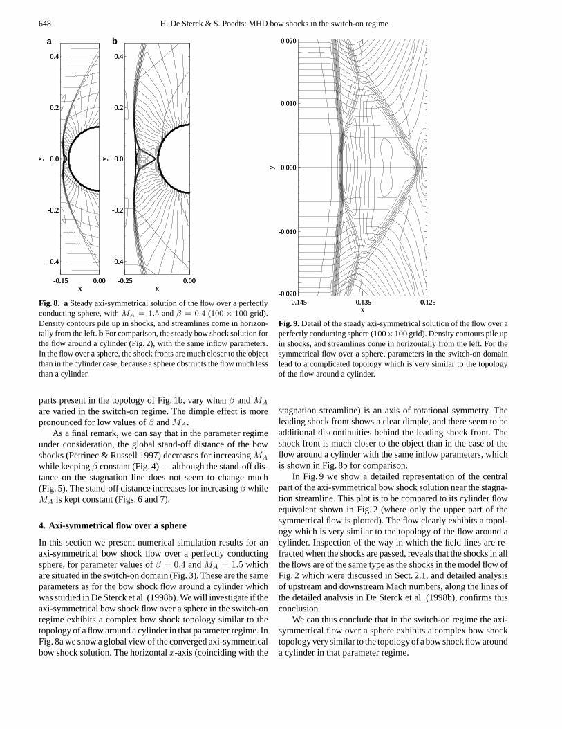
Fig. 8. aSteady axi-symmetrical solution of the flow over a perfectlyconducting sphere, withMA = 1.5 andβ = 0.4 (100 × 100 grid).Density contours pile up in shocks, and streamlines come in horizon-tally from the left.b For comparison, the steady bow shock solution forthe flow around a cylinder (Fig. 2), with the same inflow parameters.In the flow over a sphere, the shock fronts are much closer to the objectthan in the cylinder case, because a sphere obstructs the flow much lessthan a cylinder.
parts present in the topology of Fig. 1b, vary whenβ andMA
are varied in the switch-on regime. The dimple effect is morepronounced for low values ofβ andMA.
As a final remark, we can say that in the parameter regimeunder consideration, the global stand-off distance of the bowshocks (Petrinec & Russell 1997) decreases for increasingMA
while keepingβ constant (Fig. 4) — although the stand-off dis-tance on the stagnation line does not seem to change much(Fig. 5). The stand-off distance increases for increasingβ whileMA is kept constant (Figs. 6 and 7).
4. Axi-symmetrical flow over a sphere
In this section we present numerical simulation results for anaxi-symmetrical bow shock flow over a perfectly conductingsphere, for parameter values ofβ = 0.4 andMA = 1.5 whichare situated in the switch-on domain (Fig. 3). These are the sameparameters as for the bow shock flow around a cylinder whichwas studied in De Sterck et al. (1998b). We will investigate if theaxi-symmetrical bow shock flow over a sphere in the switch-onregime exhibits a complex bow shock topology similar to thetopology of a flow around a cylinder in that parameter regime. InFig. 8a we show a global view of the converged axi-symmetricalbow shock solution. The horizontalx-axis (coinciding with the
-0.145 -0.135 -0.125x
-0.020
-0.010
0.000
0.010
0.020
y
-0.145 -0.135 -0.125x
-0.020
-0.010
0.000
0.010
0.020
y
Fig. 9.Detail of the steady axi-symmetrical solution of the flow over aperfectly conducting sphere (100×100 grid). Density contours pile upin shocks, and streamlines come in horizontally from the left. For thesymmetrical flow over a sphere, parameters in the switch-on domainlead to a complicated topology which is very similar to the topologyof the flow around a cylinder.
stagnation streamline) is an axis of rotational symmetry. Theleading shock front shows a clear dimple, and there seem to beadditional discontinuities behind the leading shock front. Theshock front is much closer to the object than in the case of theflow around a cylinder with the same inflow parameters, whichis shown in Fig. 8b for comparison.
In Fig. 9 we show a detailed representation of the centralpart of the axi-symmetrical bow shock solution near the stagna-tion streamline. This plot is to be compared to its cylinder flowequivalent shown in Fig. 2 (where only the upper part of thesymmetrical flow is plotted). The flow clearly exhibits a topol-ogy which is very similar to the topology of the flow around acylinder. Inspection of the way in which the field lines are re-fracted when the shocks are passed, reveals that the shocks in allthe flows are of the same type as the shocks in the model flow ofFig. 2 which were discussed in Sect. 2.1, and detailed analysisof upstream and downstream Mach numbers, along the lines ofthe detailed analysis in De Sterck et al. (1998b), confirms thisconclusion.
We can thus conclude that in the switch-on regime the axi-symmetrical flow over a sphere exhibits a complex bow shocktopology very similar to the topology of a bow shock flow arounda cylinder in that parameter regime.

H. De Sterck & S. Poedts: MHD bow shocks in the switch-on regime 649
5. Conclusion
In this paper we have shown how symmetrical field-aligned bowshock flows around a perfectly conducting cylinder and over aperfectly conducting sphere exhibit a complex flow topology ina parameter regime which corresponds closely to the parameterregime for which switch-on shocks are possible. This provesthat the complex bow shock topology is indeed closely relatedto the possible occurrence of switch-on shocks. The topologyof the bow shock solution obtained in De Sterck et al. (1998b)and sketched in Fig. 1b is encountered for all the cylinder bowshock flows with parameters in the switch-on domain, and thistopology is thus more generally valid than only for the singleset of parameters considered in De Sterck et al. (1998b). Theshapes, sizes and shock strengths of the shock parts present inthe topology of Fig. 1b, vary whenβ andMA are varied in theswitch-on regime. The dimple effect is more pronounced forlow values ofβ andMA.
The parameter study of the cylinder flow and the result forthe axi-symmetrical flow over a sphere are extensions of the re-sult presented in De Sterck et al. (1998b). The results on MHDbow shock flows in the switch-on regime of the present pa-per, together with the detailed discussion of one example of acomplex bow shock flow in De Sterck et al. (1998b), form animportant extension of the general theory and phenomenologyof MHD bow shock flows, with possible applications in spacephysics (Petrinec & Russell 1997). Fast coronal mass ejectionsmoving away from the sun in the low-β inner corona may inducepreceding shock fronts with upstream parameters in the switch-on domain. The solar wind is normally high-β, but planetaryand cometary bow shocks may have upstream parameters in theswitch-on domain when the impinging solar wind occasionallybecomes low-β (Steinolfson & Cable 1993). The effects de-scribed by our simulations may be important for phenomena inthe Earth’s magnetosheath (Petrinec & Russell 1997, Song &Russell 1997).
The current 2D results, however, do not complete the the-ory of MHD bow shocks in the switch-on regime. If we wantto relax the condition on field-aligned flow by allowing for afinite angle between the incoming velocity and magnetic field,we have to consider the 3D ideal MHD problem of a stationaryflow around a sphere, because in a 2D flow the magnetic fluxcan not be carried around a cylinder without reconnection whenthe flow is not field-aligned. In this case the flow will lose someof its symmetries and the stationary solution may be different. Itwill be interesting to see how the intermediate shocks present inour 2D planar simulation results, would survive in a 3D contextwhich allows for non-planar perturbations. Preliminary resultsshow that also in the 3D case the leading shock front is dim-pled and is followed by a second intermediate shock front. Thisremains subject of further study.
Acknowledgements.HDS acknowledges illuminating discussionswith B. C. Low, A. Hundhausen, H. Deconinck, A. Csık, K. Powell,K. C. Hansen, and T. Barth.
References
Anderson J.E., 1963, Magnetohydrodynamic shock waves. Ph.D. The-sis, M. I. T.
Barmin A.A., Kulikovskiy A.G., Pogorelov N.V., 1996, J. Comput.Phys. 126, 77
Brio M., Wu. C.C., 1988, J. Comput. Phys. 75, 400De Sterck H., Poedts S., Goedbloed J.P., 1998a, J. Plasma Physics 59/2,
277De Sterck H., Low B.C., Poedts S., 1998b, Phys. Plasmas 5/11, 4015Freistuehler H., Szmolyan P., 1995, SIAM J. Math. Anal. 26(1), 112Gombosi T.I., Powell K.G., De Zeeuw D.L., 1994, J. Geophys.
Res. 99(A11), 21525Gombosi T.I., De Zeeuw D.L., Haberli R.L., Powell K.G., 1996, J.
Geophys. Res. 101, 15233Hundhausen A.J., 1998, Coronal mass ejections. In: Strong K.T., Saba
J.L.R., Haisch B.M., Schmelz J.T. (eds.) The many faces of thesun. Springer-Verlag, New York, 143
Kennel C.F., Blandford R.D., Coppi P., 1989, J. Plasma Physics 42,299
Leveque R.J., 1992, Numerical Methods for Conservation Laws. Lec-tures in Mathematics ETH Zurich, Birkhauser-Verlag, Basel
Linde T.J., Gombosi T.I., Roe P.L., Powell K.G., De Zeeuw D.L., 1998,J. Geophys. Res. 103(A2), 1889
Landau L.D., Lifshitz E. M, 1984, Electrodynamics of continuousmedia. Pergamon Press, Oxford
Myong R.S., Roe P.L., 1997, J. Plasma Physics 58, 521Petrinec S.M., Russell C.T., 1997, Space Sci. Rev. 79, 757Pogorelov N.V, 1995, A&A 297, 835Pogorelov, N.V., Semenov A.Yu., 1997, A&A 321, 330Powell K.G., Roe P.L., Myong R.S., Gombosi T.I., De Zeeuw D.L.,
1995, AIAA Paper 95-1704-CPQuirk J.J., 1994, Int. J. Numer. Methods Fluids 18, 555Ratkiewicz R., Barnes A., Molvik G.A., et al., 1998, A&A 335, 363Roe P.L., Balsara D.S., 1996, SIAM J. Appl. Math. 56, 57Sheeley N.R. Jr., Howard R.A., Michels D.J., et al., 1985, J. Geophys.
Res. 90, 163Song P., Russell C.T., 1997, Adv. Space Res. 20, 747Steinolfson R.S., Cable S., 1993, Geophys. Res. Lett. 20(8), 755Steinolfson R.S., Hundhausen A.J., 1990a, J. Geophys. Res. 95(A5),
6389Steinolfson R.S., Hundhausen A.J., 1990b, J. Geophys. Res. 95, 15251Steinolfson R.S., Hundhausen A.J., 1990c, J. Geophys. Res. 95(A12),
20693Tanaka T., 1993, J. Geophys. Res. 98(A10), 17251Toth G., Odstrcil D., 1996, J. Comput. Phys. 128, 82Wu C.C., 1991, New theory of mhd shock waves. In: Shearer M. (ed.)
Viscous profiles and numerical methods for shock waves. SIAMProceedings Series, SIAM, Philadelphia, 209
Wu C.C., 1992, Geophys. Res. Lett. 19(2), 87